Embed Size (px)
Citation preview
se.com/ww/ecostruxure-power
How to OptimizeTime-Synchronization and Data Recording for EcoStruxure™ Power Digital Applications
Technical Guide11/2019

www.se.com
2 How to Optimize Time Synchronization and Data Recording for EcoStruxure™ Power Digital Applications - Technical Guide
Purpose of the Document
Target AudienceThis technical guide is intended for EcoXperts, System Integrators, Application Engineers, and other qualified personnel who are responsible for the design and configuration of EcoStruxure™ Power projects.
ObjectiveThe objective of this document is to support the EcoStruxure™ Power Digital Application Design Guide, in which we introduce the digital applications and describe their implementation for large buildings and critical facilities.All the digital applications embedded in EcoStruxure™ Power Edge Control Software need to collect data from the electrical installation to enable applications such as Cost Allocation, Energy Usage Analysis, Power Event Analysis, etc., as well as to perform general trending or diagnostics. The data must be timestamped and the required accuracy of the timestamp depends on the digital applications selected.This technical guide details how to define the digital architecture to ensure proper timestamping of the collected data depending on the selected digital applications.It provides a special focus on the various methods used to time synchronize the internal clocks of advanced devices such as power meters, trip units, protective relays, PLCs, UPS controllers, Harmonic Filters, etc.
Digital Applications for Large Buildings and Critical Facilities IEC EcoStruxure™ Power Design Guide Ref: ESXP2G001EN 12/2019
Table of ContentsBack
Previous Page
Next Page
www.se.com
3How to Optimize Time Synchronization and Data Recording for EcoStruxure™ Power Digital Applications - Technical Guide
1
2
3
4
5
6
Table of Contents
INTRODUCTION ..................................................................p. 4
SECTION 1 I Defining the Required Time Criticality .............p. 9 for Your EcoStruxure™ Power Applications
SECTION 2 I Selecting the Data Timestamping/ ..................p. 15 Recording and Time-Synchronization Solution for Your Products
SECTION 3 I Implementing the Technical Solutions.............p. 23 Which Will Enable the Required Time Criticality
SECTION 4 I Application Examples .....................................p. 43
APPENDIX I Product Information .........................................p. 67
BIBLIOGRAPHY ...................................................................p. 77
Table of ContentsBack
Previous Page
Next Page

www.se.com
4 How to Optimize Time Synchronization and Data Recording for EcoStruxure™ Power Digital Applications - Technical Guide
INTRODUCTION
Overview of EcoStruxure™ Power (1/2)
IntroductionAs shown in the diagram below, and indicated by the green arrows, EcoStruxure™ Power is one of the six domains of EcoStruxure™, our IoT-enabled architecture and platform.EcoStruxure™ Power plays a key role in all four End-Markets (Building, Data Center, Industry and Infrastructure). This involves bringing the world of electrical distribution to those End-Markets.
OUR VISION OF A NEW ELECTRIC WORLD
The world is becoming more electric and digital, and power is becoming more distributed, more complex to manage, and more integrated into our everyday lives. We envision a New Electric World where building staff and occupants are safer, with zero electrical safety incidents. Where power is 100% available, with zero unplanned downtime. Where energy and operations are more efficient, with zero energy waste. And where operational systems are resilient, with zero cyber intrusions. We strive to make this vision a reality with our IoT-enabled EcoStruxure™ architecture and platform, which we deliver through our connected energy management ecosystem – a collective of partners and industry experts who are openly collaborating with us to push innovation, enhance productivity, reduce risk, and unlock new growth opportunities.
4 End-Markets addressed
6 EcoStruxure™ domains of expertise
Apps, Analytics & Services
Edge Control
Connected ProductsEnd
-to-e
nd C
yber
secu
rity
Buildings Data Centers Industry Infrastructure
EcoStruxure™ Power
EcoStruxure™ Building
EcoStruxure™ IT
EcoStruxure™ Machine
EcoStruxure™ Plant
EcoStruxure™ Grid
EcoStruxure™’s integrated architecture serves four end markets with its six domains of expertise.
Table of ContentsBack
Previous Page
Next Page

www.se.com
5How to Optimize Time Synchronization and Data Recording for EcoStruxure™ Power Digital Applications - Technical Guide
INTRODUCTION
Overview of EcoStruxure™ Power (2/2)
EcoStruxure™ Power• EcoStruxure™ Power digitizes and simplifies low and medium voltage electrical
distribution systems. It provides essential data to aid the decisions that help protect people, safeguard assets, maximize operational efficiency and business continuity, and maintain regulatory compliance.
• EcoStruxure™ Power is an open architecture and platform designed with the intention of making it easy to add, upgrade, and swap components. The world is full of electrical distribution systems in various stages of maturity; from a variety of manufacturers. Interoperability with EcoStruxure™ Power is essential to making these power distributions systems future ready. The added benefit of a holistic Schneider Electric system is the plug-and-play connectivity to achieve faster and lower risk integration and commissioning.
• EcoStruxure™ Power architectures are cost-optimized to deploy, using only the right technology to deliver the desired business outcomes for our customers – no more, no less. However, customer needs or demands change over time.
• The EcoStruxure™ Power system is scalable from light commercial and industrial buildings to critical facilities such as hospitals data centers or infrastructure like airports, rail and oil and gas. Scalability of EcoStruxure™ Power also extends to growing and evolving with changing needs or demands through its modular architecture.
• EcoStruxure™ Power architectures are fully flexible power distribution systems with the ability to adapt to dynamic and ever-changing conditions, such as balancing supply and demand by the hour or minute or adding and then scaling on-site renewable generation capabilities over time. Connecting IT and OT systems into a single, easy-to-manage Ethernet IP network is at the heart of our digitization story. With EcoStruxure™ Power, facility managers can use the data they collect to make real-time decisions to maximize business continuity and optimize operations.
More about EcoStruxure™ Powerhttps://www.schneider-electric.com/en/work/campaign/innovation/power-distribution.jsp
Table of ContentsBack
Previous Page
Next Page

www.se.com
6 How to Optimize Time Synchronization and Data Recording for EcoStruxure™ Power Digital Applications - Technical Guide
INTRODUCTION
About the Guide (1/3)
General Methodology for Optimizing Time-Synchronizationand Data Recording/TimestampingLike a common thread, the below methodology will help you understand the steps to optimize time-synchronization and data recording/timestamping for EcoStruxure™ Power digital applications, and efficiently use this guide.
PREREQUISITES – Define Your Electrical Installation and Select the Associated EcoStruxure™ Power Digital Applications
Once your electrical architecture has been designed, use the Digital Application Design Guide for Large Buildings & Critical Facilities to:• select the appropriate digital applications
for your electrical installation,• understand how to implement them,• define the connected products, software
and services that need to be embedded.
STEP 1 – Define the Required Time Criticality for Your EcoStruxure™ Power Applications
STEP 2 - Select the Data Timestamping/Recording and Time-Synchronization Solution for Your Products
There are three main families of solutions for timestamping and recording data:• using a time-synchronized connected product (Solution 1)• using Edge Control software (Solution 2)• using an external time-synchronized connected product
(Solution 3).
See Section 2, p. 17 to learn about the three main timestamping solutions
See the:Digital Applications for Large Buildings and Critical Facilities IEC EcoStruxure™ Power Design Guide Ref: ESXP2G001EN 12/2019
Most of the digital applications use connected product data which needs to be recorded and timestamped.
See Section 1, p. 11 to understand why data timestamping is useful and to learn about time accuracy and time-synchronization
Depending on the purpose of the applications, the required accuracy of the timestamps differs: Three time criticalities have been defined to describe digital applications (Low/Medium/High).
See Section 1, Table 1 p. 12 which defines time criticality
In table 2, EcoStruxure™ Power applications have been sorted by "Time Criticality".Use this table to define the required Time Criticality for the different parts of your digital installation.
See Section 1, Table 2 p. 13 to find the time criticality of the EcoStruxure™ Power digital applications
Table of ContentsBack
Previous Page
Next Page

www.se.com
7How to Optimize Time Synchronization and Data Recording for EcoStruxure™ Power Digital Applications - Technical Guide
INTRODUCTION
About the Guide (2/3)
General Methodology for Optimizing Time-Synchronizationand Data Recording/Timestamping (cont.)
STEP 2 (cont.) - Select the Data Timestamping/Recording and Time-Synchronization Solution for Your Products
STEP 3 – Implement the Technical Solutions which will Enable the Required Time Criticality
Implement the selected data timestamping and recording solutions.
See Section 3 for detailed information about the three families of solutions and their implementation
Get inspired by the implementation examples shown in Section 4.
See Section 4 for example architectures for different installation time criticalities.
Get information about connected products. See Appendix for descriptions of connected products
For advanced products which can be time synchronized, use Table 4 to select the most appropriate protocol from amongst the compatible time-synchronization protocols.
See Section 2, Table 4 p. 20 for time-synchronization protocol selection criteria
Use Table 5 to assess the time-synchronization capabilities of your EcoStruxure™ products.
See Section 2, Table 5 p. 21 for the detailed time-synchronization capabilities of main EcoStruxure™ products
The choice of family for any given connected product depends on:• the product category (Basic, Standard, Advanced)• the required time criticality (Low, Medium, High).
See Section 2, p. 18 to learn about the different categories of products
Use Table 3 to understand the selection principles.
See Table 3, p. 19 which shows the timestamping solution versus connected product category and time accuracy requirements
Table of ContentsBack
Previous Page
Next Page

www.se.com
8 How to Optimize Time Synchronization and Data Recording for EcoStruxure™ Power Digital Applications - Technical Guide
INTRODUCTION
About the Guide (3/3)
Structure of the Document
Section 1 explains why data timestamping accuracy is important while designing an EcoStruxure™ Power digital architecture and introduces the notion of digital application time criticality.
Section 2 presents the three main families of timestamping solutions as well as the main time-synchronization protocols and the selection criteria.
Section 3 provides deeper information about the technical solutions for timestamping data and time-synchronizing connected products as well as explains how to implement them.
Section 4 suggests implementation examples for digital applications with different time criticalities.
The Appendix provides a brief description of the connected products and Edge Control software stated in this guide.
The Bibliography quotes the sources of the information embedded in this guide and provides links to useful documentation.
Table of ContentsBack
Previous Page
Next Page

Introduction .......................................................................... p. 10
Why Is Time Accuracy Important When Timestamping Data for a Digital Application? ............ p. 11
What Is the Time Criticality Of a Digital Application? ........... p. 12
How to Determine the Time Criticality of EcoStruxure™ Power Digital Applications ........................... p. 13
Comparison of Applications with Different Levels of Time Criticality ...................................................... p. 14
SECTION 1
Defining the Required Time Criticality for Your EcoStruxure™ Power Applications

10
SECTION 1 I Defining the Required Time Criticality for Your EcoStruxure™ Power Applications
How to Optimize Time Synchronization and Data Recording for EcoStruxure™ Power Digital Applications - Technical Guide
www.se.com
3
4
5
6
1
2
Introduction
Why Read this Section?The objective of this section is to introduce the notion of digital application time criticality, which is fundamental when implementing EcoStruxure™ Power Applications.
Contents of this SectionFirst, we explain the importance of time accuracy when timestamping data, which can sometimes require time-synchronizing connected products.Then, to facilitate understanding, we define the notion of digital application time criticality, how it correlates with time accuracy, and we will classify EcoStruxure™ Power digital applications according to this time criticality (Low, Medium, High).Finally, to illustrate why applications require different levels of time criticality, we will review three sample applications.

11
SECTION 1 I Defining the Required Time Criticality for Your EcoStruxure™ Power Applications
How to Optimize Time Synchronization and Data Recording for EcoStruxure™ Power Digital Applications - Technical Guide
www.se.com
3
4
5
6
1
2
Why Is Time Accuracy Important When Timestamping Data for a Digital Application?
Introducing Time AccuracyIn a digital electrical installation, a lot of data is collected and recorded by connected products or by the Edge Control software. It can be recorded:• at regular intervals (for example every 15 min)• or when an event occurs (circuit breaker trip, voltage sag, transient, etc.)To enable analysis, diagnostics and operational decisions, this data must be timestamped (onboard connected products or remotely). In particular when timestamped data needs to be sorted chronologically, the accuracy of the timestamps relative to a single time reference must be sufficient with respect to the usage of the data.
Definition of Relative and Absolute Time AccuraciesThere are two kinds:
Relative Time Accuracyis the time accuracy of connected products within a system in relation to one another. As an example, a 1 ms relative time accuracy implies that all relevant device clocks in the system are within 1 ms of each other.
Absolute Time Accuracyis the accuracy with respect to the most accurate cesium atomic clock in the world.
Comment: Time Accuracy must not be confused with the resolution of a timestamp which reflects the number of decimal places. For example, the following timestamp has 1 ms precision or resolution: 3/2/2018 13:37:34.577.
Choosing Between Relative and Absolute Time AccuracyWithin a single system like EcoStruxure™ Power, we do not consider absolute time accuracy necessary for data recording and timestamping: relative time accuracy is sufficient.However, when the EcoStruxure™ Power system is connected to other EcoStruxure™ or 3rd party systems, absolute time accuracy may be required.
Need for Time-SynchronizationWhen data is recorded and timestamped on board connected products, it is important to ensure that their internal clocks are accurate in relation to other devices and local time. The setting of all the connected products to a single time reference is called time-synchronization.Time-synchronization can be implemented using several solutions as described in Section 2, p. 20.Time-synchronization solutions using time servers such as Global Navigation Satellite Systems, which are aligned with the absolute clock, provide absolute time accuracy.

12
SECTION 1 I Defining the Required Time Criticality for Your EcoStruxure™ Power Applications
How to Optimize Time Synchronization and Data Recording for EcoStruxure™ Power Digital Applications - Technical Guide
www.se.com
3
4
5
6
1
2
What Is the Time Criticality of a Digital Application?
Introducing Time CriticalityThe time accuracy required depends on data usage, and therefore on the digital application to be implemented.For ease of understanding and to simplify selection of the timestamping solution(s) for EcoStruxure™ Power digital applications, the notion of time criticality has been defined.The time criticality of a digital application reflects the level of time accuracy required for data logged by connected products to enable proper operation of the application.
Three Time Criticality LevelsIn this document, we distinguish between three levels of time criticality amongst EcoStruxure™ Power applications:
Digital Application Time Criticality Time Accuracy Upper Limit Time Accuracy Lower LimitHigh +/-1 ms +/-10 msMedium +/-10 ms +/-1 sLow +/-1 s +/-10 s
Table 1: Time criticality definition
Time Criticality and Timestamping/Time-Synchronization SolutionWhen building an efficient digital architecture, the challenge is to ensure that the solution used for data timestamping and recording is compatible with the overall time accuracy required by the selected EcoStruxure™ Power digital applications.
If the achieved time accuracy is not sufficient, due to an inappropriate timestamping solution, the application may not work properly and it may not be possible to take appropriate decisions
As will be explained in Section 2, p. 20, accurate timestamping implies, at one level or another, the implementation of time-synchronized advanced products.
Please note that the time-synchronization technologies available today are in alignment with the accuracies given in the table above.

13
SECTION 1 I Defining the Required Time Criticality for Your EcoStruxure™ Power Applications
How to Optimize Time Synchronization and Data Recording for EcoStruxure™ Power Digital Applications - Technical Guide
www.se.com
3
4
5
6
1
2
How to Determine the Time Criticality of EcoStruxure™ Power Digital Applications
Learn About EcoStruxure™ Power Digital ApplicationsUnderstanding the details of the digital applications is necessary to classify their time criticality as Low, Medium, or High.You can find all information in the Digital Applications for Large Buildings & Critical Facilities IEC Design Guide
Detailed Breakdown of Applications Relative to Their Time CriticalityThe following table shows application classifications as well as the recommended and minimum required time accuracies for each EcoStruxure™ Power application:
Application Time Criticality Recommended Time Accuracy [+/-]
Minimum Required Time Accuracy [+/-]
Continuous Thermal Monitoring Low 1 min* 5 min*Insulation Monitoring Low 1 s 10 sElectrical Distribution Monitoring & Alarming Medium 10 ms 1 sCapacity Management Low 1 s 10 sBackup Power Testing Medium 10 ms 100 msBreaker Settings Monitoring Low 1 s 10 sPower Events Analysis High 1 ms 10 msSource and Network Control Medium 10 ms 100 msPower Quality Monitoring Medium 10 ms 100 msPower Quality Correction Low 1 s 10 sUtility Bill Verification Low 1 s 10 sEnergy Benchmarking Low 1 s 10 sCost Allocation Low 1 s 10 sEnergy Usage Analysis Low 1 s 10 sEnergy Performance Analysis & Verification Low 1 s 10 sPower Factor Correction Low 1 s 10 sAsset Performance Low 1 s 10 sEnergy Efficiency Compliance Low 1 s 10 sGreenhouse Gas Reporting Low 1 s 10 sPower Quality Compliance Low 1 s 10 sRegulatory Compliance Medium 10 ms 100 ms
* For the continuous thermal monitoring application, considering the time constant of the physical phenomena observed (temperature rise of electrical conductors), time accuracy in the range of a minute is acceptable.
Table 2: Time criticality, minimum required and recommended time accuracies by EcoStruxure™ Power digital application.
Digital Applications for Large Buildings and Critical Facilities IEC EcoStruxure™ Power Design Guide Ref: ESXP2G001EN 12/2019

14
SECTION 1 I Defining the Required Time Criticality for Your EcoStruxure™ Power Applications
How to Optimize Time Synchronization and Data Recording for EcoStruxure™ Power Digital Applications - Technical Guide
www.se.com
3
4
5
6
1
2
Comparison of Applications with Different Levels of Time Criticality
IntroductionTo illustrate why applications require different levels of time criticality, we will review three sample applications:• Power Event Analysis• Electrical Distribution Monitoring & Alarming• Cost Allocation.
High Time Criticality: Power Event AnalysisThis application compares multiple events often captured by multiple connected products to determine the cause and effect of a power-related incident. When a power incident occurs in an electrical distribution system (such as transients, voltage sags...), a number of resulting events appear within a very short time frame.In this case, it is important to have tight time correlation between devices to make sure that we can diagnose the origin of an event and the exact sequence in which the incident propagated through the electrical network. With poor time accuracy, the order of the events may be wrong and may lead to inappropriate conclusions.Therefore we recommend a minimum time accuracy of 10 ms, but preferably 1 ms for this application.
Medium Time Criticality: Electrical Distribution Monitoring and AlarmingIn the case of this application, we need to make sure we accurately keep track of and record any power system status changes and control actions. Any resulting critical alarms and events are then forwarded to the user/operator who needs to understand their timing. For this purpose, a time accuracy of 1 s is typically sufficient.However, if a control action needs to be tightly correlated to power events for cause and effect analysis, refer to "Power Event Analysis" in the paragraph above.
Low Time Criticality: Cost AllocationFor Cost Allocation, where we try to assign energy costs to different areas, load types, departments, etc. within a facility, time accuracy is less important, and a time accuracy of 10 s is sufficient.
Choosing the Right Accuracy for Different Areas of Your FacilityIt is important to recognize that time accuracy is a compromise between individual applications. A decision must be made as to which application dictates the accuracy within each area of the electrical distribution system. For example, for critical loads and areas close to the incomer, the Power Event Analysis application may drive the time accuracy, whereas for non-critical loads, the Cost Allocation application could be the main accuracy driver.

Introduction .......................................................................... p. 16
What Are the Timestamping and Data Recording Solutions? .................................................. p. 17
Selecting the Timestamping and Data Recording Solution ...................................................... p. 18
Selecting the Time-Synchronization Protocol for Solution 1 ........................................................................ p. 20
SECTION 2
Selecting the Data Timestamping/Recording and Time-Synchronization Solution for Your Products

16
SECTION 2 I Selecting the Data Timestamping/Recording and Time-Synchronization Solution for Your Products
How to Optimize Time Synchronization and Data Recording for EcoStruxure™ Power Digital Applications - Technical Guide
www.se.com
3
4
5
6
2
1
Introduction
Why Read this Section?In Section 1, the notion of time criticality level was introduced and was used to classify EcoStruxure™ Power digital applications.The objective of Section 2 is to present the families of timestamping and data recording solutions which can be deployed to achieve the time criticality level requested by the selected digital applications. It also suggests criteria for selecting the most suitable solution.
Contents of this SectionThis section starts with the presentation of the three timestamping and data recording solution families:• Solution 1: timestamping and data recording by the time-synchronized connected
product itself, with a presentation of the main time-synchronization protocols• Solution 2: timestamping and data recording by the Edge Control Software,• Solution 3: timestamping and data recording by an external time-synchronized
connected product.We then define the connected product categories (Basic, Standard, Advanced).Along with the time criticality of the application, these are a criterion for selecting the most suitable timestamping solution. Keys for selection are presented and summarized in a selection table.Finally, selection criteria for time-synchronization protocols used in Solution 1 are suggested and summarized in a cost/performance selection table. The capabilities of the main EcoStruxure™ power connected products, with regard to time-synchronization protocols, are also detailed in a table.

17
SECTION 2 I Selecting the Data Timestamping/Recording and Time-Synchronization Solution for Your Products
SECTION 2 I Selecting the Data Timestamping/Recording and Time-Synchronization Solution for Your Products
How to Optimize Time Synchronization and Data Recording for EcoStruxure™ Power Digital Applications - Technical Guide
www.se.com
3
4
5
6
2
1
What Are the Timestamping and Data Recording Solutions?
Three Main FamiliesThere are three main families of solutions for timestamping and recording data. They are presented briefly below and will be detailed later in this chapter.
SOLUTION 1: Timestamping and Data Recording Using a Time-Synchronized Connected ProductSome connected products that can record data in their onboard memory and that have an internal clock are able to timestamp each recorded data point.To use their data in a system like EcoStruxure™ Power, the internal clocks on those devices must be regularly synchronized to an external reference.Section 3 presents several protocols that can be implemented:• Most of them, for example PTP, NTP, IRIG-B, etc., provide medium to high time accuracy. • Time-synchronization over Modbus or ION is commonly used. In this case, the time
server is the Edge Control software. Time accuracy with this methodology would be lower (typically in the range of +/-1 s) but still valid for non-critical applications.
Wireless technologies (using the Zigbee protocol) tend to be more and more commonly deployed in LV and MV equipment, especially for applications involving energy or environmental monitoring. However, the overall time accuracy capabilities for Zigbee-based architectures are very limited (can be up to +/-10-20 s depending on the architecture used).See Section 3 p. 25 for the implementation of time-synchronization protocols.
SOLUTION 2: Timestampingand Data Recording Using the Edge Control SoftwareThis is commonly referred to as “PC logging”: the Edge Control application retrieves a real-time reading from the connected product and then records and timestamps this reading in the Edge Control database.See Section 3, p. 36 for the implementation of PC logging.
SOLUTION 3: Timestamping and Data Recording Using an External Time-Synchronized Connected ProductThis solution is used when the connected product does not have an internal clock or cannot be time synchronized with sufficient accuracy. Data recording using an external time-synchronized connected product is most effective for recording statuses such as:• LV and MV circuit breaker status changes• Automatic Transfer Switch (ATS) status changes• Control scheme status changes• Uninterrupted Power Supply (UPS) status changes• Generator status changesSee Section 3, p. 37 for the implementation of an external time-synchronized connected product.
How do you select the timestamping and data recording solution for your needs? This is detailed on the next page.

18
SECTION 2 I Selecting the Data Timestamping/Recording and Time-Synchronization Solution for Your Products
How to Optimize Time Synchronization and Data Recording for EcoStruxure™ Power Digital Applications - Technical Guide
www.se.com
3
4
5
6
2
1
Selecting the Timestamping and Data Recording Solution (1/2)
Selection ParametersThe choice of possible timestamping solution for any given connected product depends on:• the required time accuracy (linked to the time criticality of the application to be
implemented as seen in Section 2)• the category (defined below) of the product which provides the data.
Three Categories of Connected ProductsWe can generally divide connected products into three categories, depending on their capability to manage the data they produce:
Basic Connected Products which only provide real-time data.
Standard Connected Products which only provide real-time data, energy counters and min/max/average registers.
Advanced Connected Productswith the ability to provide real-time data, energy counters, min/max/average registers and onboard data recording.
Example: Example: Example:
Easergy TH110 Wireless Thermal Sensor
Acti9 iEM3000 Energy Meter
PowerLogic PM3000 Power Meter
PowerLogic PM8000/ION9000 Power Meters
MasterPact MTZ Circuit Breaker
Not all connected products can perform accurate data timestamping. Therefore, it is important to understand which timestamping solution is suitable for which product category.
Timestamping Solution Based on Product Category
Solutions for Advanced Connected ProductsAdvanced connected products are capable of recording data in their onboard memory and have an internal clock. The connected product timestamps the recorded data itself.When high time accuracy is not required, time-synchronization over Modbus is sufficient.When high time accuracy is required, a high-accuracy time-synchronization protocol must be implemented. However, some advanced products have limited time-synchronization capabilities and can only support certain time-synchronization protocols.If higher time accuracy is required, it is possible to hardwire these to an advanced connected product with higher capabilities. The accuracy of the timestamp is then dictated by the capabilities of the most accurate advanced product.
19
SECTION 2 I Selecting the Data Timestamping/Recording and Time-Synchronization Solution for Your Products
SECTION 2 I Selecting the Data Timestamping/Recording and Time-Synchronization Solution for Your Products
How to Optimize Time Synchronization and Data Recording for EcoStruxure™ Power Digital Applications - Technical Guide
www.se.com
3
4
5
6
2
1
Selecting the Timestamping and Data Recording Solution (2/2)
Timestamping Solution Based on Product Category (cont.)
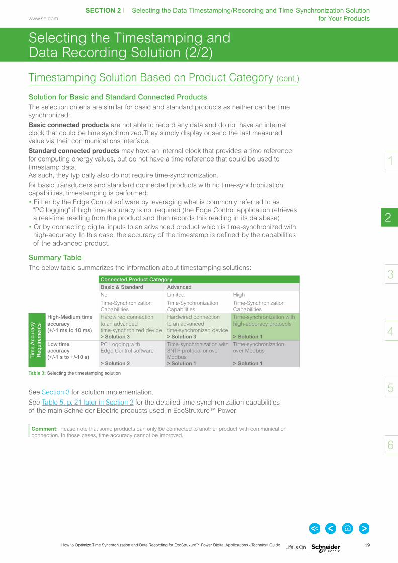
Solution for Basic and Standard Connected ProductsThe selection criteria are similar for basic and standard products as neither can be time synchronized:Basic connected products are not able to record any data and do not have an internal clock that could be time synchronized.They simply display or send the last measured value via their communications interface.Standard connected products may have an internal clock that provides a time reference for computing energy values, but do not have a time reference that could be used to timestamp data. As such, they typically also do not require time-synchronization.for basic transducers and standard connected products with no time-synchronization capabilities, timestamping is performed: • Either by the Edge Control software by leveraging what is commonly referred to as
"PC logging" if high time accuracy is not required (the Edge Control application retrieves a real-time reading from the product and then records this reading in its database)
• Or by connecting digital inputs to an advanced product which is time-synchronized with high-accuracy. In this case, the accuracy of the timestamp is defined by the capabilities of the advanced product.
Summary TableThe below table summarizes the information about timestamping solutions:
Connected Product CategoryBasic & Standard AdvancedNo Time-Synchronization Capabilities
Limited Time-Synchronization Capabilities
High Time-Synchronization Capabilities
Tim
e A
ccur
acy
Req
uire
men
ts
High-Medium time accuracy (+/-1 ms to 10 ms)
Hardwired connection to an advanced time-synchronized device > Solution 3
Hardwired connection to an advanced time-synchronized device > Solution 3
Time-synchronization with high-accuracy protocols > Solution 1
Low time accuracy (+/-1 s to +/-10 s)
PC Logging with Edge Control software > Solution 2
Time-synchronization with SNTP protocol or over Modbus > Solution 1
Time-synchronization over Modbus > Solution 1
Table 3: Selecting the timestamping solution
See Section 3 for solution implementation.See Table 5, p. 21 later in Section 2 for the detailed time-synchronization capabilities of the main Schneider Electric products used in EcoStruxure™ Power.
Comment: Please note that some products can only be connected to another product with communication connection. In those cases, time accuracy cannot be improved.

20
SECTION 2 I Selecting the Data Timestamping/Recording and Time-Synchronization Solution for Your Products
How to Optimize Time Synchronization and Data Recording for EcoStruxure™ Power Digital Applications - Technical Guide
www.se.com
3
4
5
6
2
1
Selecting the Time-Synchronization Protocol for Solution 1 (1/2)
Two Main Time-Synchronization Protocol FamiliesThe time-synchronization protocols used in Solution 1 can be sorted into two main families:
• Ethernet-Based Protocols (using an existing Ethernet network) - Precision Time Protocol (PTP) - Network Time Protocol (NTP) / Simple Network Time Protocol (SNTP) - Modbus or ION Communication Protocols
• Non Ethernet-Based Protocols (which require specific serial line wiring like IRIG-B)These protocols will be detailed in Section 3.
Selection CriteriaProtocol Selection versus Performance and CostThe choice of time-synchronization protocol is a compromise between achievable time accuracy and implementation costs.• Some of the most expensive, but most accurate time-synchronization technologies rely
on non-Ethernet protocols (for example IRIG-B, DCF77) tied to a GPS antenna, a GPS receiver and a clock.
• Ethernet-based protocols provide more economical solutions. The most cost-effective but less accurate approach is achieved with Modbus-based (or ION-based) time-synchronization over an Ethernet or serial communications network.
• Protocols such as NTP/SNTP are now commonly supported by a wide range of connected products and can provide sufficient performance for non-critical applications, typically in the range of 1 s down to 10 ms, at an affordable cost (at most a dedicated physical time server).
• A recent Ethernet-based protocol called PTP (defined in IEEE 1588 and IEC 61588) can achieve even more accurate time-synchronization, offering a strong alternative to non-Ethernet-based protocols. In order to reach the highest levels of accuracy with this protocol, specific hardware implementation is required in connected products and communication products (switches).
Selection TableAs explained in Section 1, the digital application with the greatest constraints determines the time criticality of the different parts of the installation and thus, the required time-synchronization accuracy.
The table below outlines the most suitable time-synchronization protocols according to their time criticality, as well as an estimation of associated costs.
Application Time Criticality Typical Time Accuracy Protocol Media Protocol Typical CostHigh +/-1 ms Ethernet PTP (IEEE1588)High +/-1 ms Serial IRIG-BMedium +/-10 ms to 100 ms(1) Ethernet NTPMedium +/-100 ms Serial DCF77Low +/-1 s Ethernet SNTPLow +/-1 s Ethernet Over Modbus / ION from Edge ControlLow +/-1 s Serial 1per10
(1) Achievable accuracy depends on connected product capability.
Table 4: Time-synchronization protocol selection criteria

21
SECTION 2 I Selecting the Data Timestamping/Recording and Time-Synchronization Solution for Your Products
SECTION 2 I Selecting the Data Timestamping/Recording and Time-Synchronization Solution for Your Products
How to Optimize Time Synchronization and Data Recording for EcoStruxure™ Power Digital Applications - Technical Guide
www.se.com
3
4
5
6
2
1
Selecting the Time-Synchronization Protocol for Solution 1 (2/2)
Time-Synchronization Capabilities for CommonEcoStruxure™ Power Connected Products?Summary TableAs explained in this section, not all connected products have the same time-synchronization capabilities.The following table summarizes these capabilities for the main Schneider Electric Products embedded in EcoStruxure™ Power digital architectures:Device Product Category
(as per Section 2)Logging Capabilities(1) Maximum Achievable Time-Synchronization Accuracy/
Compatible Time-Synchronization Protocols(1) (2)
Event Log Measurement Log 1 ms 10 ms / 100 ms 100 ms 1 sPTP IRIG-B NTP DCF 77 SNTP 1per10 Over
ModbusOver ION
MasterPact MTZ (with IFE/eIFE)
Advanced Limited
MasterPact NT / NW (with IFE)
Advanced Limited
ComPact NS (with IFE) Advanced LimitedComPact NSX (with IFE) Advanced LimitedActi9 Powertag Link Advanced LimitedActi9 Smartlink SI B Advanced LimitedPowerTag Energy BasicVigilohm IM20H StandardVigilohm IFL12H StandardEasergy P3 Advanced HighEasergy P5 Advanced HighEasergy Sepam 20 Series Advanced LimitedEasergy Sepam 40 Series Advanced LimitedEasergy Sepam 80 Series Advanced LimitedPowerLogic Vamp 321 Advanced HighPowerLogic Vamp 121 StandardPowerLogic Vamp 125 StandardEasergy T300 Advanced HighSMD (Modicon M251) Advanced LimitedEasergy TH110 / CL110 BasicModicon M580 Advanced LimitedModicon M580 with ERT module
Advanced High
Modicon M340 Advanced LimitedPowerLogic ION9000 Advanced HighPowerLogic PM8000 Advanced HighPowerLogic PM5000 StandardActi9 iEM3000 StandardAccusine PCS+ StandardAccusine PCSn StandardAccusine PFV+ StandardVarplus Logic StandardGalaxy VM StandardGalaxy VX StandardConnexium Managed Switches
Advanced Limited
Harmony Sologate ZBRN32 Standard
(1) Product can acquire new capabilities. Capabilities to be confirmed when ordering. (2) These are typical accuracies. Refer to product technical documentation to get information regarding the maximum achievable accuracy.
Table 5: EcoStruxure™ Power product time-synchronization capabilities
Products With Highly Accurate Time-Synchronization CapabilityIn Section 3 (Solution 1, p. 25) we explain how to implement the time-synchronization protocols for advanced products with high time-synchronization capabilities.
Products With Limited or No Time-Synchronization CapabilityAs described in the above table:• Some products have no time-synchronization capabilities• Some products can be time synchronized (over Modbus, for example), but are not
compliant with high-accuracy time protocols.Later in Section 3, we explain how to deal with such products for data recording when the implemented application requires:• low-accuracy timestamping (Solution 2, p. 36)• high-accuracy timestamping (Solution 3, p. 37).

22
SECTION 2 I Selecting the Data Timestamping/Recording and Time-Synchronization Solution for Your Products
How to Optimize Time Synchronization and Data Recording for EcoStruxure™ Power Digital Applications - Technical Guide
www.se.com
3
4
5
6
2
1

SECTION 2 I Selecting the Data Timestamping/Recording and Time-Synchronization Solution for Your Products
Introduction .......................................................................... p. 24
Solution 1: Timestamping and Data Recording Using Time-Synchronized Connected Products .................. p. 25
Solution 2: Timestamping and Data Recording Using the Edge Control ....................................................... p. 36
Solution 3: Timestamping and Data Recording Using an External Time-Synchronized Product .................... p. 37
SECTION 3
Implementing the Technical Solutions Which Will Enable the Required Time Criticality

24
SECTION 3 I Implementing The Technical Solutions Which Will Enable The Required Time Criticality
How to Optimize Time Synchronization and Data Recording for EcoStruxure™ Power Digital Applications - Technical Guide
www.se.com
2
4
5
6
3
1
Introduction
Why Read this Section?
In Section 1, the notion of time criticality level was introduced and was used to classify EcoStruxure™ Power digital applications.
Section 2 presented the three possible timestamping and data recording solutions which can be deployed to achieve the criticality level required by the digital application, as well as the selection criteria.
The objective of Section 3 is to provide information on how to implement the timestamping/time-synchronization solution presented in Section 2.
Contents of this Section
Each solution (sub-solution) is presented along with the necessary equipment, as well as examples of digital architectures for:
• Solution 1: timestamping using the time-synchronized connected product itself, with a presentation of the main time-synchronization protocols (IRIG B, DCF77, 1per10, NTP/SNTP, PTP, Modbus/ION).
• Solution 2: timestamping using the Edge Control Software (PC Logging).
• Solution 3: timestamping using an externally time-synchronized connected product (PowerLogic ION9000/PM8000 Power Meter, Modicon M580 PAC Timestamping Module, 3rd Party Sequence of Event Recorder).

25
SECTION 3 I Implementing The Technical Solutions Which Will Enable The Required Time Criticality
How to Optimize Time Synchronization and Data Recording for EcoStruxure™ Power Digital Applications - Technical Guide
www.se.com
2
4
5
6
3
1
Solution 1: Timestamping and Data Recording Using Time-Synchronized Connected Products (1/11)
TYPICAL CHARACTERISTICSTime-Synchronization Source• GPS antenna + Time server
Accuracy• +/-1 ms (IRIG-B)• +/-100 ms (DCF77)• +/-1 s (1per10)
Required Hardware• GPS antenna• Time server• Dedicated cables and distribution modules
Device Compatibility• Most MV protection relays, PLCs and
high-end power meters support at least one of these protocols.
Limitations• Requires dedicated cabling• Can be expensive
Figure 1: IRIG-B timecode signal
Figure 2: DCF77 timecode signal
TimeOn-timePoint
24 VDC
200 ms
100 ms
logical 0logical 1
Non-Ethernet-Based Time Protocols (Serial)PRESENTATIONTime-synchronization based on non-Ethernet protocols uses a time reference provided by a GPS antenna, relayed to the connected product clocks by a GPS Receiver.As the name suggests, those time-synchronization protocols do not use the Ethernet network.Therefore, in addition to the installation of the GPS antenna and receiver, they require the installation of specific coaxial cables.Although effective, the use of such protocols is expensive.The most common serial GPS-based time protocols include:• IRIG-B,• DCF77• 1per10.
About IRIG-B [1]IRIG (Inter Range Instrumentation Group) is a series of serial timecodes, commonly used by electric utilities and industries for time-synchronization purposes in power management systems.IRIG timecodes use a continuous stream of binary data to transmit information on date and time, typically distributed at 5 VDC and wired point-to-point.There are six different formats of IRIG timecodes depending on pulse rate attributes such as:• Modulated or un-modulated• Carrier frequency• Type of coded expression.The most commonly used format is modulated IRIG-B (1 kHz carrier).
About DCF77 [2]DCF77 is a time-synchronization protocol with its origin in Germany. When used as an electrical signal, the DCF77 timecode is transmitted as a 24 VDC pulse-width modulated signal that provides a complete date/time string once every minute. The signal contains a one-pulse-per-second component that is accurate to 100 microseconds in reference to UTC (Coordinated Universal Time).As DCF77 uses 24 Vdc nominal voltage, it can be distributed to multiple products over long distances, making it well suited to power and automation applications. Thanks to its relatively low bit rate of 1 pulse-per-second and time frame of 1 minute (compared to 100 pps and 1 second for IRIG-B), DCF77 requires less processor overhead, yet can achieve equivalent accuracies.

26
SECTION 3 I Implementing The Technical Solutions Which Will Enable The Required Time Criticality
How to Optimize Time Synchronization and Data Recording for EcoStruxure™ Power Digital Applications - Technical Guide
www.se.com
2
4
5
6
3
1
Non-Ethernet-Based Time Protocols (serial) (cont.)
Solution 1: Timestamping and Data Recording Using Time-Synchronized Connected Products (2/11)
Figure 3: 1per10 timecode signal
0 10 20 30Seconds
40 50 60
Start of Minute10 sec
Typical Architecture
Specific cabling for time-synchronizationSerial (antenna cable)Serial (for IRIG-B)Serial (for 1per10)Serial (DCF-77)
GPS antenna
1
GPS receiver / Satellite time server
2
IRIG-B Distribution module
3
Power products
5Power products
5Power products
5
4 4 4
IRIG-B (24 VDC unmodulated)
IRIG-B (5 VDC unmodulated)
DCF-771per10
PRESENTATION (cont.)
About 1per10 [3]1per10 (one-pulse-per-ten-seconds) is a simple time protocol that uses one synchronizing pulse every 10 seconds to provide an accurate time reference for power system products. The rising edge of the first 1per10 pulse occurs at the exact start of a minute, and subsequent pulses follow at 10 second intervals. Since only the rising edge is used for synchronization, the width (duration) of the pulse is not important. The diagram on the right shows a typical 1per10 signal.
IMPLEMENTATION
Main Components Involved 1 GPS antenna• This component is mounted on the roof or other external location,
allowing line-of-sight access to multiple satellites• It retrieves absolute time over one or (ideally) various GNSS
systems, such as GPS (US), Galileo (Europe), Beidou (China).• The antenna generates a pulse-per-second (PPS) output
synchronized to UTC with a precision of a few nanoseconds. 2 GPS receiver / Satellite time server• This device is in charge of sending the time reference to
the power products over a dedicated serial line. Many time servers can distribute this time reference over one or more serial protocols (IRIG-B, DCF-77, 1per10).
3 IRIG-B distribution module• When the time reference signal must be distributed over long
distances, distribution modules operating at 24 VDC are required • These modules then distribute the signal with the IRIG-B
unmodulated 5 VDC protocol, as most of the power products only support this IRIG-B protocol.
4 Communication cables• The type of cable will depend on the protocol used.
Table 6, p. 27 details the specifications of serial cables for each time-synchronization protocol.
5 Power products • These protocols require the use of products with provisions
for synchronizing to a GPS time signal over a serial line. Power system products such as power meters and protective relays with onboard clocks are often equipped with such capabilities
• Devices may support one or more of the protocols (See Table 5, p. 21 for detailed product capabilities).
Figure 4: Typical architecture using non-Ethernet-based time protocols for product time-synchronization

27
SECTION 3 I Implementing The Technical Solutions Which Will Enable The Required Time Criticality
How to Optimize Time Synchronization and Data Recording for EcoStruxure™ Power Digital Applications - Technical Guide
www.se.com
2
4
5
6
3
1
Solution 1: Timestamping and Data Recording Using Time-Synchronized Connected Products (3/11)
Non-Ethernet-Based Time Protocols (serial) (cont.)
IMPLEMENTATION (cont.)
Cabling Specifications Which Impact System ArchitectureDepending on the non-Ethernet protocol used, the maximum permissible number of synchronized connected products, the maximum cabling distance and the type of cables used differ, as summarized in the table below.
Non-Ethernet-Based Time-Synchronization Protocol
Maximum Number of Devices
Maximum Distance Recommended Cable
Cable Specifications
IRIG-B Unmodulated (24 V DCLS) 8 600 m (2000 ft.) Belden 8770 (or equiv.)
Shielded, 3-conductor cable, copper, #18AWG, 300 V rms
Unmodulated (5 V DCLS) 4 300 m (1000 ft.) Belden 8760 (or equiv.)
Shielded, twisted-pair cable, copper, #18AWG, 300 V rms
Modulated 4 1200 m (4000 ft.) Belden 8760 (or equiv.)
Shielded, twisted-pair cable, copper, #18AWG, 300 V rms
DCF77 16 1200 m (4000 ft.) Belden 8760 (or equiv.)
Shielded, twisted-pair cable, copper, #18AWG, 300 V rms
1per10 16 600 m (2000 ft.) Belden 8760 (or equiv.)
Shielded, twisted-pair cable, copper, #18AWG, 300 V rms
Table 6: Cabling recommendations for non-Ethernet-based time-synchronization protocols

28
SECTION 3 I Implementing The Technical Solutions Which Will Enable The Required Time Criticality
How to Optimize Time Synchronization and Data Recording for EcoStruxure™ Power Digital Applications - Technical Guide
www.se.com
2
4
5
6
3
1
Solution 1: Timestamping and Data Recording Using Time-Synchronized Connected Products (4/11)
Non-Ethernet-Based Time Protocols (serial) (cont.)
EXAMPLE OF DIGITAL ARCHITECTUREBelow is an example of a digital architecture that implements time-synchronization using several non-Ethernet-based communication protocols:
Figure 5: Example of an architecture that implements time-synchronization via IRIG-B, DCF77 and 1per10 time protocols, using a GPS antenna
Edge Control
Connected Products
EthernetSerial (antenna cable)Serial (for IRIG-B)Serial (for 1per10)Serial (DCF-77)
EcoStruxure™ Power Monitoring Expert
OR
EcoStruxure™ Power SCADA Operation with Advanced Reporting & Dashboards
PowerLogic PM8000 Power Meter
Easergy Sepam 80 Protection Relay
Ethernet Switch
Modicon M580 PAC with BMXERT Timestamping Card
IRIG-B
1per10
DCF-77
Time Server
Onboard alarms and events with accurate timestamp and time quality information
GPS Antenna
NTP time-synchronization
NTP time-synchronization
Timestamp
Timestamp
Timestamp

29
SECTION 3 I Implementing The Technical Solutions Which Will Enable The Required Time Criticality
How to Optimize Time Synchronization and Data Recording for EcoStruxure™ Power Digital Applications - Technical Guide
www.se.com
2
4
5
6
3
1
Solution 1: Timestamping and Data Recording Using Time-Synchronized Connected Products (5/11)
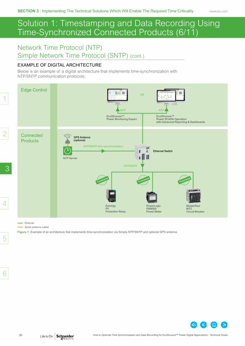
Network Time Protocol (NTP) Simple Network Time Protocol (SNTP)PRESENTATIONNetwork Time Protocol (NTP) is a highly robust protocol, widely deployed throughout the Internet. Well tested over the years, it is generally regarded as state-of-the-art in distributed time-synchronization protocols for unreliable networks. A simplified version of the NTP protocol, SNTP, can also be used as a pure single-shot stateless master-slave synchronization protocol. Both full NTP and SNTP rely on the same architecture and use the same data packet from a time server message.The only difference is that SNTP does not include all the sophisticated algorithms used by NTP to correct and adjust time accuracy. As a result the accuracy will be limited to a 1 s range while full NTP implementation can lead to 10/100 ms accuracy.
IMPLEMENTATION
Main Components Involved 1 GPS antenna (optional)• This component is mounted on the roof or other external location,
allowing line-of-sight access to multiple satellites• It retrieves absolute time over one or (ideally) various GNSS
systems, such as GPS (US), Galileo (Europe), Beidou (China), etc. 2 NTP server• Synchronizes all client clocks connected to its own clock. 3 NTP client• Can be any connected product supporting time-synchronization
through NTP. Specific algorithms (e.g. Clock filter, clock select.) are implemented in the product in order to match full NTP implementation requirements and achieve the highest level of accuracy.
TYPICAL CHARACTERISTICS
Time-Synchronization Source• NTP Time server
Accuracy• +/-10 ms to +/-100 ms depending on
product level of support• +/-1 s for SNTP
Required Hardware• NTP time server
Device Compatibility• NTP support or at minimum SNTP is
widespread among power products
Limitations• Not suitable for critical applications
Typical Architecture
GPS antenna
1
NTP server
2
NTP client NTP client 3
EthernetSerial (antenna cable)
NTP
Comment 1: This architecture also applies to synchronization using the SNTP protocol.
Comment 2: The architecture above is a simplified version of the NTP architecture. Complex systems may involve several layers of NTP servers (called stratum). In this case, several communication mechanisms are used to ensure proper time-synchronization between servers: • Master / Client• Peer-to-peer• Broadcast.
Figure 6: Typical architecture using NTP for product time-synchronization
30
SECTION 3 I Implementing The Technical Solutions Which Will Enable The Required Time Criticality
How to Optimize Time Synchronization and Data Recording for EcoStruxure™ Power Digital Applications - Technical Guide
www.se.com
2
4
5
6
3
1
Solution 1: Timestamping and Data Recording Using Time-Synchronized Connected Products (6/11)
Network Time Protocol (NTP) Simple Network Time Protocol (SNTP) (cont.)
EXAMPLE OF DIGITAL ARCHITECTUREBelow is an example of a digital architecture that implements time-synchronization with NTP/SNTP communication protocols:
Figure 7: Example of an architecture that implements time-synchronization via Simple NTP/SNTP and optional GPS antenna
EthernetSerial (antenna cable)
Edge Control
Connected Products
EcoStruxure™ Power Monitoring Expert
OR
EcoStruxure™ Power SCADA Operation with Advanced Reporting & Dashboards
NTP Server
GPS Antenna (optional)
PowerLogic PM8000 Power Meter
Easergy P5 Protection Relay
NTP/SNTP
Ethernet Switch
NTP/SNTP time-synchronization
NTP NTP
MasterPact MTZ Circuit Breaker
Timestamp
Timestamp
Timestamp

31
SECTION 3 I Implementing The Technical Solutions Which Will Enable The Required Time Criticality
How to Optimize Time Synchronization and Data Recording for EcoStruxure™ Power Digital Applications - Technical Guide
www.se.com
2
4
5
6
3
1
Solution 1: Timestamping and Data Recording Using Time-Synchronized Connected Products (7/11)
Precision Time Protocol (PTP) / IEEE 1588PRESENTATIONPTP was designed to respond to the weaknesses of NTP and to give better accuracies than those attainable with NTP. It has also been designed for applications that cannot support the cost of a GPS receiver on each connected product, or for which GPS signals are inaccessible, and in particular for measurement and control systems.Refer to the “Time-synchronization and Protection and Control” white paper by Henri GrassetIn addition to PTP system-related settings, the accuracy of your product’s clock also depends on the physical network configuration. A star network topology is highly recommended in order to achieve the level of clock precision specified.
IMPLEMENTATIONMain Components Involved 1 GPS antenna (optional)• This component is mounted on the roof or other external location,
allowing line-of-sight access to multiple satellites• It retrieves absolute time over one or (ideally) various GNSS
systems, such as GPS (US), Galileo (Europe), Beidou (China). 2 IEEE 1588 grandmaster clock• The Grandmaster clock can provide precise nanosecond
timestamp resolution and accuracy better than 30 nanoseconds referenced to GPS.
3 IEEE 1588 transparent clock• A transparent clock is an Ethernet switch that handles
IEEE-1588 packets differently compared to a standard switch. The transparent clock measures the time that the packet is stored in the switch. It then adds the measured time into the correction field of the follow-up message. To account for the packet delay, the slave clock uses the origin timestamp and the correction field.
4 IEEE 1588 boundary clock• A boundary clock is an Ethernet switch that handles IEEE-1588
packets differently compared to a standard switch or transparent switch. The subnets to a network must isolate PTP packets when installing a boundary clock. The boundary clock acts much like an ordinary clock on the network and becomes the master clock on the isolated subnets.
5 IEEE 1588 slave clocks (connected products)• Any product supporting time-synchronization through PTP protocol.
TYPICAL CHARACTERISTICS
Time-Synchronization Source• PTP Master Clock
Accuracy• +/-1 ms for “Simple” PTP• Better than +/-1 ms for standard PTP profiles
Required Hardware• IEEE 1588 compliant Master clocks• IEEE 1588 compliant Ethernet switches
(boundary and/or transparent clocks)
Device Compatibility• Easergy T300• High-end power meters
(PowerLogic ION9000, PM8000)
Limitations• Few connected products currently support
PTP / IEEE1588
Typical Architecture
EthernetEthernet or serial (time reference source connection)
GPS antenna
1
Grandmaster clock
2
Power product (Slave clocks)
Power product (Slave clocks)
Power product (Slave clocks)
5
Transparent clock
3
Boundary clock
4
Figure 8: PTP timestamps
T1
T4
T3
T2
Master slave messages
Master clock Slave clock
TimeSync message
Sync follow-up message
Delay request message
Delay response message
Figure 9: Typical architecture using PTP for product time-synchronization
32
SECTION 3 I Implementing The Technical Solutions Which Will Enable The Required Time Criticality
How to Optimize Time Synchronization and Data Recording for EcoStruxure™ Power Digital Applications - Technical Guide
www.se.com
2
4
5
6
3
1
Solution 1: Timestamping and Data Recording Using Time-Synchronized Connected Products (8/11)
Precision Time Protocol (PTP) / IEEE 1588 (cont.)
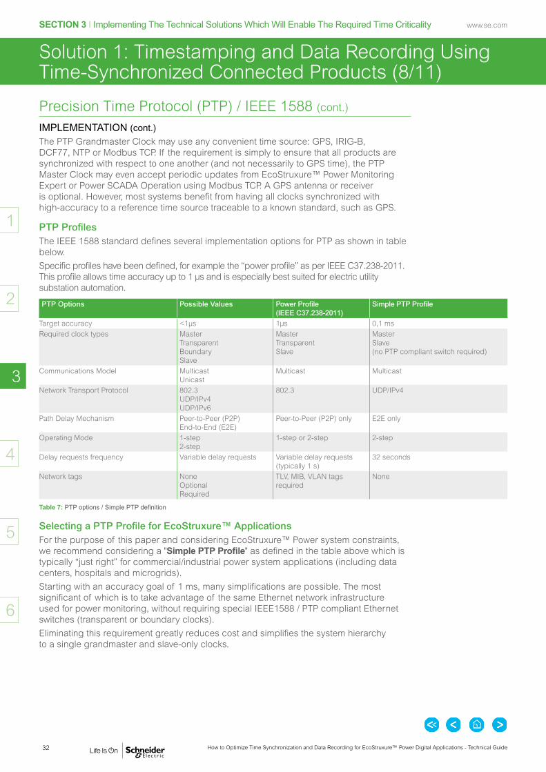
IMPLEMENTATION (cont.)The PTP Grandmaster Clock may use any convenient time source: GPS, IRIG-B, DCF77, NTP or Modbus TCP. If the requirement is simply to ensure that all products are synchronized with respect to one another (and not necessarily to GPS time), the PTP Master Clock may even accept periodic updates from EcoStruxure™ Power Monitoring Expert or Power SCADA Operation using Modbus TCP. A GPS antenna or receiver is optional. However, most systems benefit from having all clocks synchronized with high-accuracy to a reference time source traceable to a known standard, such as GPS.
PTP ProfilesThe IEEE 1588 standard defines several implementation options for PTP as shown in table below.Specific profiles have been defined, for example the “power profile” as per IEEE C37.238-2011. This profile allows time accuracy up to 1 µs and is especially best suited for electric utility substation automation.
PTP Options Possible Values Power Profile (IEEE C37.238-2011)
Simple PTP Profile
Target accuracy <1µs 1µs 0,1 msRequired clock types Master
Transparent Boundary Slave
Master Transparent Slave
Master Slave (no PTP compliant switch required)
Communications Model Multicast Unicast
Multicast Multicast
Network Transport Protocol 802.3 UDP/IPv4 UDP/IPv6
802.3 UDP/IPv4
Path Delay Mechanism Peer-to-Peer (P2P) End-to-End (E2E)
Peer-to-Peer (P2P) only E2E only
Operating Mode 1-step 2-step
1-step or 2-step 2-step
Delay requests frequency Variable delay requests Variable delay requests (typically 1 s)
32 seconds
Network tags None Optional Required
TLV, MIB, VLAN tags required
None
Table 7: PTP options / Simple PTP definition
Selecting a PTP Profile for EcoStruxure™ ApplicationsFor the purpose of this paper and considering EcoStruxure™ Power system constraints, we recommend considering a "Simple PTP Profile" as defined in the table above which is typically “just right” for commercial/industrial power system applications (including data centers, hospitals and microgrids).Starting with an accuracy goal of 1 ms, many simplifications are possible. The most significant of which is to take advantage of the same Ethernet network infrastructure used for power monitoring, without requiring special IEEE1588 / PTP compliant Ethernet switches (transparent or boundary clocks). Eliminating this requirement greatly reduces cost and simplifies the system hierarchy to a single grandmaster and slave-only clocks.
33
SECTION 3 I Implementing The Technical Solutions Which Will Enable The Required Time Criticality
How to Optimize Time Synchronization and Data Recording for EcoStruxure™ Power Digital Applications - Technical Guide
www.se.com
2
4
5
6
3
1
Solution 1: Timestamping and Data Recording Using Time-Synchronized Connected Products (9/11)
Precision Time Protocol (PTP) / IEEE 1588 (cont.)
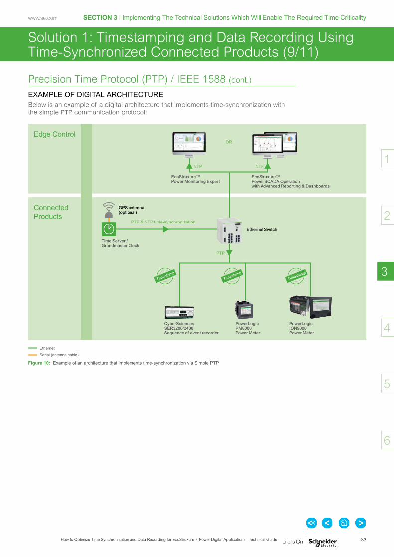
EXAMPLE OF DIGITAL ARCHITECTUREBelow is an example of a digital architecture that implements time-synchronization with the simple PTP communication protocol:
EthernetSerial (antenna cable)
Edge Control
Connected Products
EcoStruxure™ Power Monitoring Expert
OR
EcoStruxure™ Power SCADA Operation with Advanced Reporting & Dashboards
Time Server / Grandmaster Clock
GPS antenna (optional)
PowerLogic PM8000 Power Meter
PTP
Ethernet Switch
PTP & NTP time-synchronization
NTP NTP
CyberSciences SER3200/2408 Sequence of event recorder
PowerLogic ION9000 Power Meter
Figure 10: Example of an architecture that implements time-synchronization via Simple PTP
Timestamp
Timestamp
Timestamp
34
SECTION 3 I Implementing The Technical Solutions Which Will Enable The Required Time Criticality
How to Optimize Time Synchronization and Data Recording for EcoStruxure™ Power Digital Applications - Technical Guide
www.se.com
2
4
5
6
3
1
Solution 1: Timestamping and Data Recording Using Time-Synchronized Connected Products (10/11)
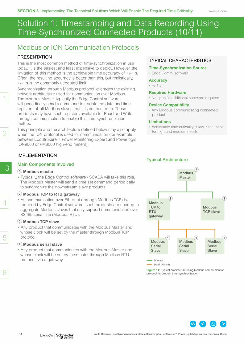
Modbus or ION Communication ProtocolsPRESENTATIONThis is the most common method of time-synchronization in use today. It is the easiest and least expensive to deploy. However, the limitation of this method is the achievable time accuracy of +/-1 s. Often, the resulting accuracy is better than this, but realistically, +/-1 s is the commonly accepted limit.Synchronization through Modbus protocol leverages the existing network architecture used for communication over Modbus. The Modbus Master, typically the Edge Control software, will periodically send a command to update the date and time registers of all Modbus slaves that it is connected to. These products may have such registers available for Read and Write through communication to enable this time-synchronization method.This principle and the architecture defined below may also apply when the ION protocol is used for communication (for example between EcoStruxure™ Power Monitoring Expert and Powerlogic ION9000 or PM8000 high-end meters).
IMPLEMENTATION
Main Components Involved 1 Modbus master• Typically, the Edge Control software / SCADA will take this role.
The Modbus Master will send a time set command periodically to synchronize the downstream slave products.
2 Modbus TCP to RTU gateway• As communication over Ethernet (through Modbus TCP) is
required by Edge Control software, such products are needed to aggregate Modbus slaves that only support communication over RS485 serial line (Modbus RTU).
3 Modbus TCP slave• Any product that communicates with the Modbus Master and
whose clock will be set by the master through Modbus TCP protocol.
4 Modbus serial slave• Any product that communicates with the Modbus Master and
whose clock will be set by the master through Modbus RTU protocol, via a gateway.
TYPICAL CHARACTERISTICS
Time-Synchronization Source• Edge Control software
Accuracy• +/-1 s
Required Hardware• No specific additional hardware required
Device Compatibility• Any Modbus communicating connected
product
Limitations• Achievable time criticality is low, not suitable
for high and medium needs
Typical Architecture
Modbus Master
1
Modbus TCP to RTU gateway
2
Modbus TCP slave
3
EthernetSerial (RS485)
Modbus Serial Slave
4Modbus Serial Slave
4Modbus Serial Slave
4
Figure 11: Typical architecture using Modbus communication protocol for product time-synchronization

35
SECTION 3 I Implementing The Technical Solutions Which Will Enable The Required Time Criticality
How to Optimize Time Synchronization and Data Recording for EcoStruxure™ Power Digital Applications - Technical Guide
www.se.com
2
4
5
6
3
1
Solution 1: Timestamping and Data Recording Using Time-Synchronized Connected Products (11/11)
Modbus or ION Communication Protocols (cont.)
EXAMPLE OF DIGITAL ARCHITECTUREBelow is an example of a digital architecture that implements time-synchronization with Modbus/ION communication protocols:
Communication MediumEthernetSerial (RS485)
Edge Control
Connected Products
EcoStruxure™ Power Monitoring Expert
OR
EcoStruxure™ Power SCADA Operation with Advanced Reporting & Dashboards
Modbus TCP / ION
Modbus RTUPowerLogic ION9000 Power Meter
NTP NTP
MasterPact MTZ Circuit Breaker
EnerLin'X Link 150 Gateway
Easergy Sepam 20 Protection Relay
Figure 12: Example of an architecture that implements time-synchronization via Modbus / ION
Modbus TCP / ION time-synchronization
Time Server
NTP time-synchronizationEthernet Switch
Timestamp
Timestamp
Timestamp

36
SECTION 3 I Implementing The Technical Solutions Which Will Enable The Required Time Criticality
How to Optimize Time Synchronization and Data Recording for EcoStruxure™ Power Digital Applications - Technical Guide
www.se.com
2
4
5
6
3
1
Solution 2: Timestamping and Data Recording Using the Edge Control
PC Logging from Edge ControlPRESENTATIONWhen field devices do not support onboard event or data logging, an option to consider is to have the Edge Control software log and timestamp the data. This methodology is often referred to as PC logging. It is less accurate than field device onboard data logging (accuracy can be >10 s) but can provide sufficient performance for less demanding applications.
EXAMPLE OF DIGITAL ARCHITECTUREBelow is an example of a digital architecture implementing timestamping by Edge Control:
Communication MediumEthernetSerial (RS485)HardwiredWireless
Edge Control
Connected Products
EcoStruxure™ Power Monitoring Expert
OR
EcoStruxure™ Power SCADA Operation with Advanced Reporting & Dashboards
Modbus TCP time-synchronization
EnerLin'X Link 150 Gateway
Acti9 IC60 Miniature Circuit Breaker
Acti9 Smartlink SI B Gateway
Acti9 Powertag Energy Sensor
Compact Powertag NSX Energy Sensor
PowerLogic PM5000 Power Meters
Harmony ZBRN32 (sologate) Wireless Data Concentrator
Easergy TH110 Temperature Sensor
Figure 13: Example of an architecture that implements PC logging
NTP NTP
Modbus TCP / ION
Time Server
NTP time-synchronizationEthernet Switch
Modbus RTU
Timestamp
Timestamp

37
SECTION 3 I Implementing The Technical Solutions Which Will Enable The Required Time Criticality
How to Optimize Time Synchronization and Data Recording for EcoStruxure™ Power Digital Applications - Technical Guide
www.se.com
2
4
5
6
3
1
Solution 3: Timestamping and Data Recording Using an External Time-Synchronized Product (1/5)
Presentation of the Problem
For critical applications, a high time accuracy (down to 1 ms) is required.
However, as shown in Table 5, p. 21, some products do not support accurate enough time-synchronization (not better than 1 second accuracy) for critical applications.
Typical examples are:• LV and MV circuit breaker status changes• Automatic Transfer Switch (ATS) status
changes• Control scheme status changes• UPS status changes• Generator status changes.
In the above examples, highly accurate data recording and timestamping is required for Power Event Analysis applications.
How can we sufficiently improve the timestamp accuracy of these status changes?
Technical Options
In order to log such status changes with high time accuracy, these statuses must be hardwired to products having the capabilities to:• Log status changes / events• Be synchronized through a highly
accurate protocol (ideally Ethernet-based such as PTP).
On the following pages, we will detail three technical options which meet these requirements:• Using PowerLogic ION9000/PM8000
Powermeter’s digital Input Channels• Using Modicon M580 PAC*’s digital Input
Channels• Using a 3rd party sequence of event
recorder (SER-3200 or SER-2408).
This will improve the time accuracy of the recorded data to that of the advanced data recording product.
Device Type Statuses to Be Monitored with Accurate Timestamp
Number of Digital Inputs per Product
MV circuit breaker (withdrawable)
OPEN CLOSED TRIPPED CONNECTED (CE) DISCONNECTED (CD) TEST BREAKER CONTROL
7
MV circuit breaker (non withdrawable)
OPEN CLOSED TRIPPED TEST BREAKER CONTROL
5
LV circuit breaker (withdrawable)
OPEN CLOSED TRIPPED CONNECTED (CE) DISCONNECTED (CD) TEST
6
LV circuit breaker (non withdrawable)
OPEN CLOSED TRIPPED
3
Automatic Transfer Switch (ATS)
NORMAL EMERGENCY TEST
3
Control scheme AUTO MANUAL TEST
3
UPS NORMAL BYPASS
2
Generator STARTING RUNNING STOPPED
3
Table 8: Product statuses to be monitored with accurate timestamp
* PAC stands for Programmable Automation Controller

38
SECTION 3 I Implementing The Technical Solutions Which Will Enable The Required Time Criticality
How to Optimize Time Synchronization and Data Recording for EcoStruxure™ Power Digital Applications - Technical Guide
www.se.com
2
4
5
6
3
1
Solution 3: Timestamping and Data Recording Using an External Time-Synchronized Product (2/5)
Using PowerLogic ION9000/PM8000 Powermeter’s Digital Input ChannelsPRESENTATIONPowerLogic ION9000 and PM8000 are accurately synchronized with IRIG-B, NTP, or PTP. They both have integrated and optional I/O capabilities to retrieve other product statuses:• PowerLogic ION9000:
- 8 digital inputs (embedded) - + 6 digital inputs per optional module (max. 4 modules).
• PowerLogic PM8000: - 3 digital inputs (embedded) - + 6 digital inputs per optional module (max. 4 modules).
EXAMPLE OF DIGITAL ARCHITECTUREThe diagram below displays the setup needed to retrieve Masterpact NT/NW withdrawable circuit breaker statuses using a PowerLogic advanced power meter, time synchronized with IRIG-B protocol. Events and alarms from the circuit breaker will be identified as onboard alarms generated by the advanced meter.
EthernetSerial (for IRIG-B)Hardwired
Edge Control
Connected Products
EcoStruxure™ Power Monitoring Expert
OR
EcoStruxure™ Power SCADA Operation with Advanced Reporting & Dashboards
Ethernet Switch
Onboard alarms and events with accurate timestamp and time quality information
Live data measurements
GPS Antenna
PowerLogic PM8000 (or ION9000) Power Meter
MasterPact NT/NW Circuit Breaker
Circuit Breaker Statuses: DI1: OPEN DI2: CLOSED DI3: TRIPPED DI4: CONNECTED (CD contact) (withdrawable breaker only) DI5: DISCONNECTED (CD contact) (withdrawable breaker only)
NTP NTP
PTP
NTP time-synchronization
Time Server
Timestamp
Figure 14: Example of an architecture that implements timestamping and data recording using PowerLogic PM8000 (ION9000) powermeter's digital input channels

39
SECTION 3 I Implementing The Technical Solutions Which Will Enable The Required Time Criticality
How to Optimize Time Synchronization and Data Recording for EcoStruxure™ Power Digital Applications - Technical Guide
www.se.com
2
4
5
6
3
1
Solution 3: Timestamping and Data Recording Using an External Time-Synchronized Product (3/5)
Using Modicon M580 PAC's* Timestamping ModulePRESENTATION
Timestamping and SynchronizationIn the power system, protection products may not communicate directly with the supervision system; instead they may communicate through a PLC* or PAC*.This architecture can be used to improve the response time to get data displayed in the supervision system. Indeed, instead of sending queries to multiple products, the supervision system sends one query to the PLC* to retrieve data from all the products connected to it. Standalone PLCs* or Hot-Standby PAC* (Modicon M580 or legacy Quantum) can be used to log events. A time resolution of 1 ms can be reached using a Modicon BMXERT digital input module supporting highly accurate timestamping. The IRIG-B 004/5/6/7 or DCF77 signals generated by a GPS receiver are used to synchronize the BMXERT module’s time clock.In addition, an external NTP server may be used to provide the time clock for the PLC / PAC* CPUs. In a Modicon M580 distributed architecture, the M580 CPU can act as an NTP server to synchronize its I/O drops module’s time clock.
Edge Control ConnectivityEdge Control software will retrieve timestamped events and alarms through OPC (Open Platform Communications). One advantage of this methodology is that it does not require any specific programming on the PAC*, just configuration (using OPC Factory Server OFS). This implementation also enables direct communication between the timestamping modules (BMXERT) and the Edge Control software; as a result, the available communication bandwidth in the PAC* is preserved.
* PLC stands for Programmable Logic Controller PAC stands for Programmable Automation Controller
For more information about how to retrieve timestamped data from EcoStruxure™ Power SCADA Operation using OFS, please consult the Power SCADA Operation system guide:
EcoStruxure™ Power SCADA Operation 9.0 with Advanced Reporting & Dashboards
System Guide Ref: PowerSCADAOperationSystemGuide 7EN02-0413-00 09/2018
https://www.se.com/en/download/document/PowerSCADAOperationSystemGuide/
40
SECTION 3 I Implementing The Technical Solutions Which Will Enable The Required Time Criticality
How to Optimize Time Synchronization and Data Recording for EcoStruxure™ Power Digital Applications - Technical Guide
www.se.com
2
4
5
6
3
1
Solution 3: Timestamping and Data Recording Using an External Time-Synchronized Product (4/5)
Using Modicon M580 PAC's* Timestamping Module (cont.)
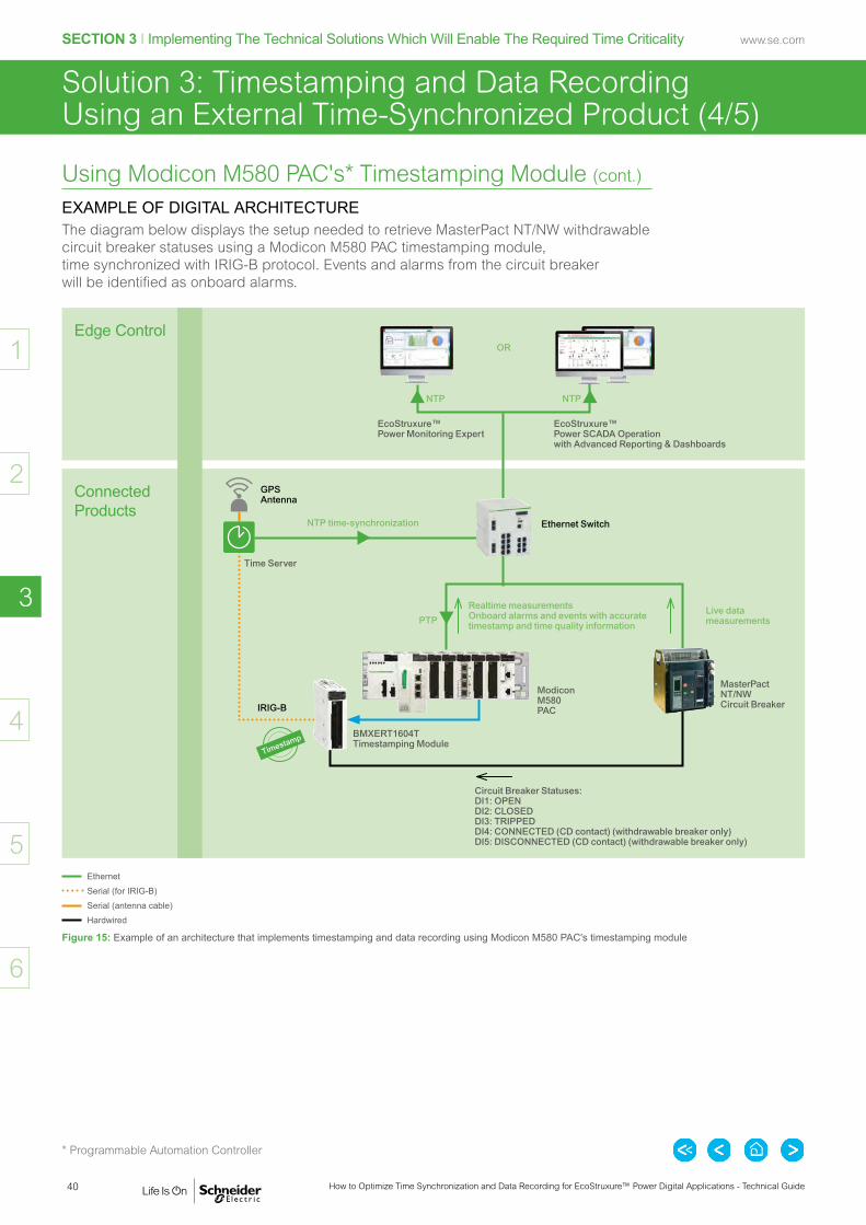
EXAMPLE OF DIGITAL ARCHITECTUREThe diagram below displays the setup needed to retrieve MasterPact NT/NW withdrawable circuit breaker statuses using a Modicon M580 PAC timestamping module, time synchronized with IRIG-B protocol. Events and alarms from the circuit breaker will be identified as onboard alarms.
* Programmable Automation Controller
EthernetSerial (for IRIG-B)Serial (antenna cable)Hardwired
Edge Control
Connected Products
EcoStruxure™ Power Monitoring Expert
OR
EcoStruxure™ Power SCADA Operation with Advanced Reporting & Dashboards
Ethernet Switch
IRIG-B
Realtime measurements Onboard alarms and events with accurate timestamp and time quality information
Live data measurements
MasterPact NT/NW Circuit Breaker
Circuit Breaker Statuses: DI1: OPEN DI2: CLOSED DI3: TRIPPED DI4: CONNECTED (CD contact) (withdrawable breaker only) DI5: DISCONNECTED (CD contact) (withdrawable breaker only)
Modicon M580 PAC
BMXERT1604T Timestamping Module
NTP NTP
PTP
NTP time-synchronization
GPS Antenna
Time Server
Timestamp
Figure 15: Example of an architecture that implements timestamping and data recording using Modicon M580 PAC's timestamping module

41
SECTION 3 I Implementing The Technical Solutions Which Will Enable The Required Time Criticality
How to Optimize Time Synchronization and Data Recording for EcoStruxure™ Power Digital Applications - Technical Guide
www.se.com
2
4
5
6
3
1
Solution 3: Timestamping and Data Recording Using an External Time-Synchronized Product (5/5)
Using a 3rd Party Sequence of Event Recorder (Cyber Sciences™ SER-3200 or SER-2408)PRESENTATIONThe Cyber Sciences™ company manufactures Sequence of Events Recorders. They provide precise timestamped event reporting for up to 32 channels to enable root-cause analysis and advanced system diagnostics. The Sequence of Events Recorders themselves are accurately synchronized with IRIG-B, DCF77, or PTP.The I/O configuration for the 32 channels varies by model:• SER-3200—32 high-speed digital inputs• SER-2408—24 high-speed digital inputs and 8 control relay outputs.These products are natively supported in EcoStruxure™ Power Monitoring Expert (PME 8.2 and onwards) and Power SCADA Operation (PSE 7.40 and onwards).
EXAMPLE OF DIGITAL ARCHITECTUREThe diagram below displays the setup to retrieve Masterpact NT/NW circuit breaker statuses using a Cyber Sciences™ sequence of event recorder, time synchronized with IRIG-B protocol. Events and alarms from the circuit breaker will be identified as onboard alarms in the sequence of events recorder:
Edge Control
Connected Products
EcoStruxure™ Power Monitoring Expert
OR
EcoStruxure™ Power SCADA Operation with Advanced Reporting & Dashboards
Ethernet Switch
Realtime measurements Onboard alarms and events with accurate timestamp and time quality information
MasterPact NT/NW Circuit Breaker
Circuit Breaker Statuses: DI1: OPEN DI2: CLOSED DI3: TRIPPED DI4: CONNECTED (CD contact) (withdrawable breaker only) DI5: DISCONNECTED (CD contact) (withdrawable breaker only)
Cyber Sciences™ SER3200 / SER2408 Sequence of Events Recorder
EthernetSerial (for IRIG-B)Serial (antenna cable)Hardwired
PTP & NTP time-synchronization
GPS Antenna
Time server
NTP NTP
PTP
Timestamp
Figure 16: Example of an architecture that implements timestamping and data recording using Cyber Sciences™ SER-3200 or SER-2408 sequence of event module

42
SECTION 3 I Implementing The Technical Solutions Which Will Enable The Required Time Criticality
How to Optimize Time Synchronization and Data Recording for EcoStruxure™ Power Digital Applications - Technical Guide
www.se.com
2
4
5
6
3
1

Introduction .......................................................................... p. 44
Defining the Electrical Installation and Selecting the Digital Applications ........................................ p. 45
Defining the Time Criticality of the Electrical Distribution System ........................................ p. 53
Implementing the Power Event Analysis Application ........... p. 54
Implementing the Electrical Distribution Monitoring & Alarming Application ........................................................ p. 59
Implementing the Cost Allocation Application ..................... p. 63
SECTION 4
Application Examples

44
SECTION 4 I Application Examples
How to Optimize Time Synchronization and Data Recording for EcoStruxure™ Power Digital Applications - Technical Guide
www.se.com
2
3
5
6
4
1
Introduction
Why Read this Section?The general principles and main technologies for timestamping and time-synchronization have been presented in previous sections.The aim of Section 4 is to provide concrete examples of how to implement an adapted timestamping solution, depending on the application’s time criticality level.
Contents of this SectionThis section will follow the methodology presented in this document’s introduction (p. 6).We:• Define a generic electrical installation for our study,• Select three case study applications from amongst the applicable EcoStruxure™
Power Applications.
For each case study application, we:• Define the data to be retrieved and associated connected products specific
for the application;• Deduce the appropriate timestamping and time-synchronization solution(s),
depending on the time criticality of each application;• suggest associated timestamping and time-synchronization architecture(s).

45
SECTION 4 I Application Examples
How to Optimize Time Synchronization and Data Recording for EcoStruxure™ Power Digital Applications - Technical Guide
www.se.com
2
3
5
6
4
1
(1/8)Defining the Electrical Installation and Selecting the Digital Applications
Definition of the Electrical Distribution ArchitectureThe first step of the methodology is to define the electrical installation of the building.For the purpose of this section, below is a diagram which defines a generic electrical installation on which we will illustrate the various implementation scenarios of data timestamping and time-synchronization:
MV
MV/LV
LV
Loads
Main MV switchgear
LV Genset switchboard
Main LV switchboard A
Secondary DSB A
Final DSB A1
Final DSB A1
Utility 1 Utility 2 (Backup)
Genset,DG1
Genset,DG2
Genset,DG3
UPS A2
UPS A1
Main LV switchboard B
Secondary DSB B
Final DSB B1
Final DSB B2
UPS B2
UPS B1
MV/LV TRA_A
MV/LV TRA_B
Figure 17: Generic electrical architecture
Each orange box will be further detailed in the following pages, both in terms of single line diagram and digital architecture.

46
SECTION 4 I Application Examples
How to Optimize Time Synchronization and Data Recording for EcoStruxure™ Power Digital Applications - Technical Guide
www.se.com
2
3
5
6
4
1
(2/8)
Selecting the Applications
APPLICABLE ECOSTRUXURE™ POWER APPLICATIONSOnce the electrical architecture has been defined, we must select the EcoStruxure™ Power digital applications to embed, in order to meet the requirements of the building/facility. The list of applications can be found in Table 2 p.13 in Section 1. Further information about the applications’ purpose is available in Section 1 of EcoStruxure™ Power Digital Application Design Guide.
SELECTED APPLICATIONS FOR OUR STUDYTo illustrate the various needs for time accuracy and their implementation in the electrical distribution system, let’s select some applications, representative for various time criticality levels:• High Time Criticality: Power Event Analysis• Medium Time Criticality: Electrical Distribution Monitoring & Alarming• Low Time Criticality: Cost Allocation.
Defining the Electrical Installation and Selecting the Digital Applications
Digital Applications for Large Buildings and Critical Facilities IEC EcoStruxure™ Power Design Guide Ref: ESXP2G001EN 12/2019
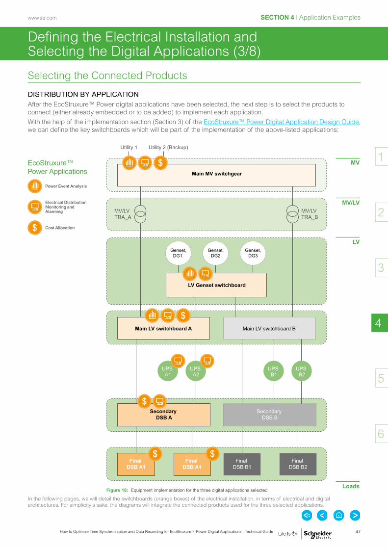
47
SECTION 4 I Application Examples
How to Optimize Time Synchronization and Data Recording for EcoStruxure™ Power Digital Applications - Technical Guide
www.se.com
2
3
5
6
4
1
(3/8)Defining the Electrical Installation and Selecting the Digital Applications
Selecting the Connected Products
DISTRIBUTION BY APPLICATIONAfter the EcoStruxure™ Power digital applications have been selected, the next step is to select the products to connect (either already embedded or to be added) to implement each application.With the help of the implementation section (Section 3) of the EcoStruxure™ Power Digital Application Design Guide, we can define the key switchboards which will be part of the implementation of the above-listed applications:
MV
MV/LV
LV
Loads
Main MV switchgear
LV Genset switchboard
Main LV switchboard A
Secondary DSB A
Final DSB A1
Final DSB A1
Utility 1 Utility 2 (Backup)
Genset,DG1
Genset,DG2
Genset,DG3
UPS A2
UPS A1
Main LV switchboard B
Secondary DSB B
Final DSB B1
Final DSB B2
UPS B2
UPS B1
MV/LV TRA_A
MV/LV TRA_B
Figure 18: Equipment implementation for the three digital applications selected
In the following pages, we will detail the switchboards (orange boxes) of the electrical installation, in terms of electrical and digital architectures. For simplicity’s sake, the diagrams will integrate the connected products used for the three selected applications.
EcoStruxure™ Power Applications
Power Event Analysis
Electrical Distribution Monitoring and Alarming
Cost Allocation

48
SECTION 4 I Application Examples
How to Optimize Time Synchronization and Data Recording for EcoStruxure™ Power Digital Applications - Technical Guide
www.se.com
2
3
5
6
4
1
(4/8)Defining the Electrical Installation and Selecting the Digital Applications
Selecting the Connected Products (cont.)
DETAILED VIEW OF MAIN MV SWITCHGEARWe focus here on the MV switchgear of our predefined generic electrical distribution architecture.
Electrical ArchitectureThe diagram below details the MV distribution switchboard’s single line diagrams. This MV switchgear includes the following equipment:• Two utility incomers with one automatic transfer system (managed with Easergy T300)• One main MV incomer circuit breaker (with Easergy P3 protection relay) equipped with one incoming advanced
power quality meter (ION9000) • Two feeder circuit breakers (with Easergy P3 protection relays).
MV
Utility 1
Utility 2(Backup)
Easergy P3*Easergy P3*Easergy P3* ION9000*Easergy T300
Feeder to MV/LV transformers
TRA_BTRA_AFigure 19: Main MV switchgear – Single-line diagram

49
SECTION 4 I Application Examples
How to Optimize Time Synchronization and Data Recording for EcoStruxure™ Power Digital Applications - Technical Guide
www.se.com
2
3
5
6
4
1
(5/8)Defining the Electrical Installation and Selecting the Digital Applications
Selecting the Connected Products (cont.)
DETAILED VIEW OF MAIN MV SWITCHGEAR (cont.)
Digital ArchitectureThe diagram below details the digital architecture of the main MV switchgear:
Figure 20: Main MV switchgear – Digital architecture
Ethernet – Technical LANSerial - RS485Hardwired
Easergy P3
Easergy T300
Harmony Sologate ZBRN32
PowerLogic ION9000

50
SECTION 4 I Application Examples
How to Optimize Time Synchronization and Data Recording for EcoStruxure™ Power Digital Applications - Technical Guide
www.se.com
2
3
5
6
4
1
(6/8)Defining the Electrical Installation and Selecting the Digital Applications
Selecting the Connected Products (cont.)
DETAILED VIEW OF MAIN, GENSET AND SECONDARY LV SWITCHBOARD
Electrical ArchitectureThe diagram below details the key LV distribution switchboard’s single line diagrams:• Main LV Switchboard• LV Genset Switchboard• LV Secondary Distribution Switchboard
Feeder to Main LVswitchboard A
Feeder to Main LVswitchboard B
Feeder to Loadbank
DG1 DG2 DG3
TRA_A incomer Gensetincomer
Tie-breaker (to other Main LV)
Feeder to UPS A1 Feeder to UPS A2
By-pass tosecondary
switchboard
UPS A1incomer
UPS A1 UPS A2
UPS A2incomer
Bypassincomer
Load bank feeder
Feeder to final distribution board A1
Feeder to final distribution board A2
Figure 21: Main, genset and secondary switchboard – Single-line diagram
LV Genset Switchboard
Main LV Switchboard
LV Secondary Switchboard

51
SECTION 4 I Application Examples
How to Optimize Time Synchronization and Data Recording for EcoStruxure™ Power Digital Applications - Technical Guide
www.se.com
2
3
5
6
4
1
(7/8)Defining the Electrical Installation and Selecting the Digital Applications
Selecting the Connected Products (cont.)
DETAILED VIEW OF MAIN, GENSET AND SECONDARY LV SWITCHBOARD (cont.)
Main LV Switchboard Digital ArchitectureTypical functions of the main LV switchboard include:• Large incomer circuit breakers and bus-tie (MasterPact MTZ) equipped with power
quality meter (PowerLogic PM8000)• Large feeder circuit breakers (MasterPact MTZ)• Automatic Transfer System (based on PLC M340 / M580).
LV Genset Switchboard Digital ArchitectureTypical functions of the LV Genset switchboard include:• Large Diesel Generator incomer circuit breakers (MasterPact MTZ) equipped with power
quality meter (PowerLogic PM8000)• Large feeder circuit breakers (MasterPact MTZ)
LV Secondary Switchboard Digital ArchitectureTypical functions of the LV Genset switchboard include:• Large incomer circuit breakers and switch disconnectors (MasterPact MTZ)• Small feeder circuit breakers (ComPact NSX), equipped with basic power meters when
critical load energy monitoring is required (PowerLogic PM5000).
Figure 22: Main LV switchboard – Digital architecture
Figure 23: LV Genset switchboard – Digital architecture
Figure 24: LV Secondary switchboard – Digital architecture
Ethernet – Technical LAN
Ethernet – Technical LAN
Masterpact MTZ with Micrologic X
PowerLogic PM8000
PowerLogic PM5000
Connexium
Modicon M580
ComPact NSX
Enerlin’X EIFE
Enerlin’X IFE gateway
Enerlin’X IFM
Ethernet – Technical LANSerial - RS485

52
SECTION 4 I Application Examples
How to Optimize Time Synchronization and Data Recording for EcoStruxure™ Power Digital Applications - Technical Guide
www.se.com
2
3
5
6
4
1
(8/8)Defining the Electrical Installation and Selecting the Digital Applications
Selecting the Connected Products (cont.)
DETAILED VIEW OF LV FINAL DISTRIBUTION PANELBOARD
Electrical ArchitectureTypical functions of an LV final distribution panel board include:• One incomer circuit breaker (ComPact NSX) with or without embedded metering
capacity• Feeders protected by miniature circuit breakers (Acti9) • Basic energy metering per feeder (Acti9 iEM3000).Other specific functions, such as insulation monitoring devices may be installed at this level of the architecture.
Digital ArchitectureEnergy data for the Cost Allocation application can be obtained either through wired or wireless devices; the respective digital architectures for these two categories are shown hereafter.
Figure 25: LV final distribution panelboard – Single-line diagram
Figure 26: LV final distribution panelboard with wired energy metering – Digital architecture
Figure 27: LV final distribution panelboard with wireless energy metering - Digital architecture
Ethernet – Technical LANSerial - RS485
Ethernet – Technical LAN
Wireless
Connexium
Enerlin’X IFE gateway
Enerlin’X Link150
EM EM EM EM EM EM
ComPact NSX
Acti9 iC60 with zigBee I/O module
Acti9 Powertag Link
Acti9 IEM3000
PowerLogic PowerTag NSX
PowerLogic PowerTag
IFE gateway Link150

53
SECTION 4 I Application Examples
How to Optimize Time Synchronization and Data Recording for EcoStruxure™ Power Digital Applications - Technical Guide
www.se.com
2
3
5
6
4
1
Defining the Time Criticality of the Electrical Distribution System
Time Criticality of the Selected ApplicationsThe choice of solution for timestamping the data depends on the recommended time accuracy illustrated by the time criticality of each application.The table below, which defines the time criticality of our selected applications, is an extract of Table 2, p. 13:
Time Criticality of the Digital InstallationWhen a system uses several applications, the most stringent time accuracy requirements must be considered when defining the solution for timestamping the data. Time accuracy requirements shall also be considered according to the criticality of the load supplied, i.e. per switchboard or panelboard.In the following pages, for simplicity’s sake, we will consider the three applications separately.
Applications Time Criticality Recommended Time Accuracy [+/-]
Minimum Required Time Accuracy [+/-]
Power Events Analysis High 1 ms 100 msElectrical Distribution Monitoring & Alarming Medium 10 ms 1 sCost Allocation Low 1 s 10 sTable 9: Recommended time accuracy for the selected applications (extract of Table 2)

54
SECTION 4 I Application Examples
How to Optimize Time Synchronization and Data Recording for EcoStruxure™ Power Digital Applications - Technical Guide
www.se.com
2
3
5
6
4
1
(1/5)Implementing the Power Event Analysis Application
Data to Be RetrievedWith the help of the implementation section (Section 3) of the EcoStruxure™ Power Digital Application Design Guide, we can define what data needs to be retrieved in the different parts of the installation and which key equipment is able to provide it.
MV
MV/LV
LV
Loads
Main MV switchgear
LV Genset switchboard
Main LV switchboard A
Secondary DSB A
Final DSB A1
Final DSB A1
Utility 1 Utility 2 (Backup)
Genset,DG1
Genset,DG2
Genset,DG3
UPS A2
UPS A1
Main LV switchboard B
Secondary DSB B
Final DSB B1
Final DSB B2
UPS B2
UPS B1
MV/LV TRA_A
MV/LV TRA_B
Figure 28: Data to be retrieved for the Power Event Analysis application and associated devices
Easergy P3
Easergy T300
PowerLogic ION9000
MasterPact MTZ
MasterPact MTZ
PowerLogic PM8000
PowerLogic PM8000
Modicon M580 (ATS)
Circuit Breaker• Position (open,
closed, racked-in, racked-out, etc)
• Trip status, protection status
Genset• Statuses• Operating modes
or conditions • (RUN, STOP,
STARTING)
ATS• Status, events
and diagnostic information
• Normal, test, emergency
Status from EquipmentElectrical Measurements From Utilities and the ED Network• Current, voltage, energy• Power (Active, Reactive, Apparent)• Frequency• Power factor• Harmonic distortion• Voltage and current unbalance• Sags, swells

55
SECTION 4 I Application Examples
How to Optimize Time Synchronization and Data Recording for EcoStruxure™ Power Digital Applications - Technical Guide
www.se.com
2
3
5
6
4
1
(2/5)Implementing the Power Event Analysis Application
Selecting the Timestamping Solution
TIMESTAMPING OPTIONS FOR HIGHLY TIME CRITICAL APPLICATIONSAs explained in Section 2, the Power Event Analysis application’s time criticality is high, with a recommended time accuracy of 1 ms. According to the extract of Table 4 p. 20 in Section 2 below, this can be achieved by time synchronizing devices with IRIG-B or PTP protocols.
Application Time Criticality Typical Accuracy Protocol Media Protocol Typical Cost
High +/-1 ms Ethernet PTP (IEEE1588)
High +/-1 ms Serial IRIG-B
Table 10: Recommended time accuracy for the selected applications (Extract from Table 2)
Using Table 2, p. 13 in Section 1, we can check the capabilities of the devices at stake to implement the Power Event Analysis application, for IRIG-B or PTP protocols and deduce the most suitable solution.
OPTION A: FULL IRIG-B BASED ARCHITECTURESynchronization with IRIG-B protocol enables the most complete timestamped data collection: many embedded field devices support this protocol such as the Easergy P3 and T300, PowerLogic PM8000, and Modicon M580 with ERT timestamping module.Devices with no IRIG-B capabilities (e.g.: MasterPact MTZ), can be hardwired to products which support IRIG-B and will timestamp the data for them. It can be:• a high-end meter (such as Powerlogic PM8000) already installed for Power Quality
monitoring• a specifically added time-synchronized device, such as a PAC (Modicon M580) or
Sequence of Event Recorder.
OPTION B: PTP-BASED ARCHITECTURESynchronization with PTP is easier and less expensive, but is compatible with fewer field devices.Some products, like Easergy T300, PowerLogic ION9000 and PM8000 intrinsically support the PTP protocol.As Easergy P3 is not PTP compatible, we suggest collecting and timestamping information from MV circuit breaker statuses using digital inputs of Easergy T300. Without an Easergy T300 present, ION 9000 digital inputs can be used.MasterPact, which also does not support PTP, should be hardwired to another device which supports PTP and will timestamp the data. Here, we suggest connecting MasterPact statuses to an embedded PowerLogic PM8000 when available and to add sequence of event recorders if PM8000 digital inputs cannot be used to relay the statuses.
OPTION C: HYBRID ARCHITECTURE (PTP / IRIG-B)Due to limitations on product capabilities regarding supported time-synchronization, pure PTP time-synchronization implementation is not yet achievable with systems such as the one given in this example. On the other hand, pure IRIG-B / serial line based protocols can lead to significant extra cost. A good compromise for data collection with high time accuracy can be achieved by combining the benefits of both protocols (PTP and IRIG-B), to make the most of each device's capability. This is also facilitated by the fact that many master clocks can act as master for both types of protocols (PTP, IRIG-B, but also DCF77 or NTP if needed).
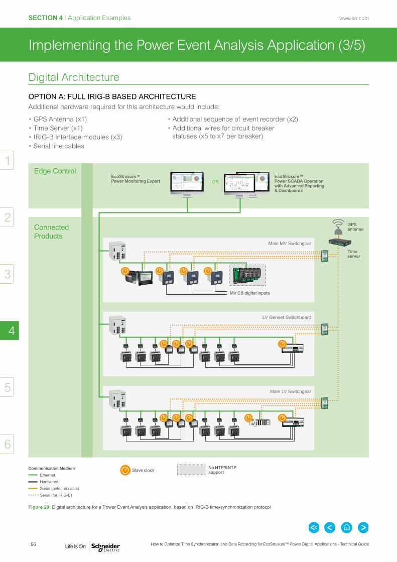
56
SECTION 4 I Application Examples
How to Optimize Time Synchronization and Data Recording for EcoStruxure™ Power Digital Applications - Technical Guide
www.se.com
2
3
5
6
4
1
(3/5)Implementing the Power Event Analysis Application
Digital Architecture
OPTION A: FULL IRIG-B BASED ARCHITECTUREAdditional hardware required for this architecture would include:
• GPS Antenna (x1)• Time Server (x1)• IRIG-B interface modules (x3)• Serial line cables
• Additional sequence of event recorder (x2)• Additional wires for circuit breaker
statuses (x5 to x7 per breaker)
Edge Control
Connected Products
Main LV Switchgear
Communication MediumEthernetHardwiredSerial (antenna cable)Serial (for IRIG-B)
EcoStruxure™ Power Monitoring Expert OR
EcoStruxure™ Power SCADA Operation with Advanced Reporting & Dashboards
Figure 29: Digital architecture for a Power Event Analysis application, based on IRIG-B time-synchronization protocol
GPS antenna
MV CB digital inputs
Main MV Switchgear
LV Genset Switchboard
Time server
Slave clock No NTP/SNTP support

57
SECTION 4 I Application Examples
How to Optimize Time Synchronization and Data Recording for EcoStruxure™ Power Digital Applications - Technical Guide
www.se.com
2
3
5
6
4
1
(4/5)Implementing the Power Event Analysis Application
Digital Architecture (cont.)
OPTION B: PTP-BASED ARCHITECTUREAdditional hardware required for this architecture would include:
• PTP Grandmaster Clock• Additional sequence of event recorder (x3)• Additional wires for circuit breaker statuses (x5 to x7 per breaker)
Master clock
Slave clock
Edge Control
Connected Products
Communication MediumEthernetHardwiredSerial (antenna cable)Serial (for IRIG-B)
EcoStruxure™ Power Monitoring Expert OR
EcoStruxure™ Power SCADA Operation with Advanced Reporting & Dashboards
Figure 30: Digital architecture for a Power Event Analysis application, based on PTP time-synchronization protocol
LV Genset Switchboard
MV CB digital inputs
Main MV SwitchgearPTP Grand-Master Clock
Main LV Switchgear
No PTP support
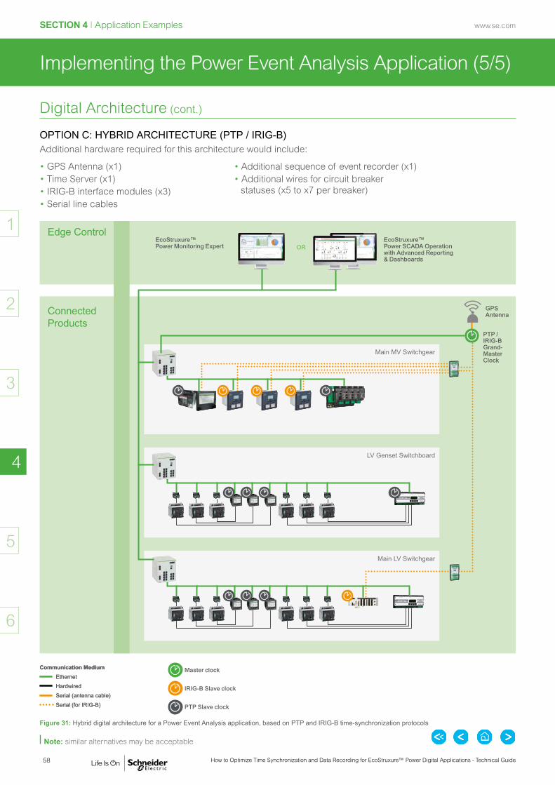
58
SECTION 4 I Application Examples
How to Optimize Time Synchronization and Data Recording for EcoStruxure™ Power Digital Applications - Technical Guide
www.se.com
2
3
5
6
4
1
(5/5)
Digital Architecture (cont.)
OPTION C: HYBRID ARCHITECTURE (PTP / IRIG-B)Additional hardware required for this architecture would include:
Master clock
IRIG-B Slave clock
PTP Slave clock
Communication MediumEthernetHardwiredSerial (antenna cable)Serial (for IRIG-B)
Figure 31: Hybrid digital architecture for a Power Event Analysis application, based on PTP and IRIG-B time-synchronization protocols
Implementing the Power Event Analysis Application
Edge Control
Connected Products
Main LV Switchgear
Communication MediumEthernetHardwiredSerial (antenna cable)Serial (for IRIG-B)
EcoStruxure™ Power Monitoring Expert OR
EcoStruxure™ Power SCADA Operation with Advanced Reporting & Dashboards
GPS Antenna
Main MV Switchgear
LV Genset Switchboard
PTP / IRIG-B Grand-Master Clock
Note: similar alternatives may be acceptable
• GPS Antenna (x1)• Time Server (x1)• IRIG-B interface modules (x3)• Serial line cables
• Additional sequence of event recorder (x1)• Additional wires for circuit breaker
statuses (x5 to x7 per breaker)

59
SECTION 4 I Application Examples
How to Optimize Time Synchronization and Data Recording for EcoStruxure™ Power Digital Applications - Technical Guide
www.se.com
2
3
5
6
4
1
(1/4)Implementing the Electrical Distribution Monitoring & Alarming Application
Data to Be RetrievedWith the help of the implementation section (Section 3) of the EcoStruxure™ Power Digital Application Design Guide, we can define what data needs to be retrieved in the different parts of the installation and which key equipment is able to provide it.
MV
MV/LV
LV
Loads
Main MV switchgear
LV Genset switchboard
Main LV switchboard A
Secondary DSB A
Final DSB A1
Final DSB A1
Utility 1 Utility 2 (Backup)
Genset,DG1
Genset,DG2
Genset,DG3
UPS A2
UPS A1
Main LV switchboard B
Secondary DSB B
Final DSB B1
Final DSB B2
UPS B2
UPS B1
MV/LV TRA_A
MV/LV TRA_B
Figure 32: Data to be retrieved for the Electrical Distribution Monitoring & Alarming application and associated devices
Easergy P3
Easergy T300
PowerLogic ION9000
MasterPact MTZ
PowerLogic PM8000
Modicon M580 (ATS)
Circuit Breaker• Position (open,
closed, racked-in, racked-out, etc.)
• Trip status, protection status
• Genset• Statuses• Operating modes
or conditions • (RUN, STOP,
STARTING)UPS• Statuses
ATS• Status, events
and diagnostic information
• Normal, test, emergency
Status from EquipmentElectrical Measurements From Utilities and the ED Network• Current, voltage, energy• Power (Active, Reactive,
Apparent)• Frequency• Power factor• Harmonic distortion• Voltage and current unbalance
Other Physical Measurements• Temperature• Humidity
Other Information• Other statuses, operating
modes or conditions• Control actions (operator
or automatic)
Galaxy VM/VX
PowerLogic PM5000
PowerLogic PowerTag NSX
PowerLogic PowerTag
ComPact NSX
ComPact NSX
Acti9 iEM3000

60
SECTION 4 I Application Examples
How to Optimize Time Synchronization and Data Recording for EcoStruxure™ Power Digital Applications - Technical Guide
www.se.com
2
3
5
6
4
1
(2/4)Implementing the Electrical Distribution Monitoring & Alarming Application
Selecting the Timestamping Solution
TIMESTAMPING OPTIONS FOR MEDIUM TIME CRITICAL APPLICATIONSAs explained in Section 2, the Electrical Distribution Monitoring & Alarming Application’s time criticality is medium, with a recommended time accuracy of 10 ms (maximum 1 s). According to the extract of Table 4 p. 20 in Section 2 below, this can be achieved by time synchronizing devices with NTP/SNTP or DCF77 protocols, or over Modbus/ION. Application Time Criticality Typical Accuracy Protocol Media Protocol Typical Cost
Medium +/-10 ms to 100 ms Ethernet NTP
Medium +/-100 ms Serial DCF77
Medium +/-1 s Ethernet SNTP
Medium +/-1 s Ethernet Over Modbus / ION
-
Table 11: Characteristics of time-synchronization for medium time criticality applications
Using Table 2, p. 13 in Section 1, we can check, for the above protocols, the capabilities of the devices at stake to implement the Electrical Distribution Monitoring & Alarming application.As very few field devices can support the DCF77, we suggest implementing time-synchronization with SNTP-NTP or Modbus/ION, with the advantage of being less expensive for the former and without cost for the latter.
SOLUTION A: SNTP-NTP PROTOCOLA few high-end devices (such as PowerLogic ION9000 and PM8000, MasterPact MTZ with IFE) support true NTP which allows time accuracy in the range of +/-10 to +/-100 ms. For many EcoStruxure™ Power field devices, the simplified version of NTP (called SNTP) has been implemented; SNTP relies on the same network architecture but achievable accuracy performances are typically lower, in the range of +/-1 s.
SOLUTION B: SYNCHRONIZATION OVER MODBUS / IONSynchronization over Modbus or ION communication protocol can provide sufficient accuracy when Electrical Distribution Monitoring and Alarming is deployed for less critical applications. In this case, a +/-1 s accuracy is commonly achievable, and the advantage is that it comes without any additional cost with device integration in Edge Control software for most cases.
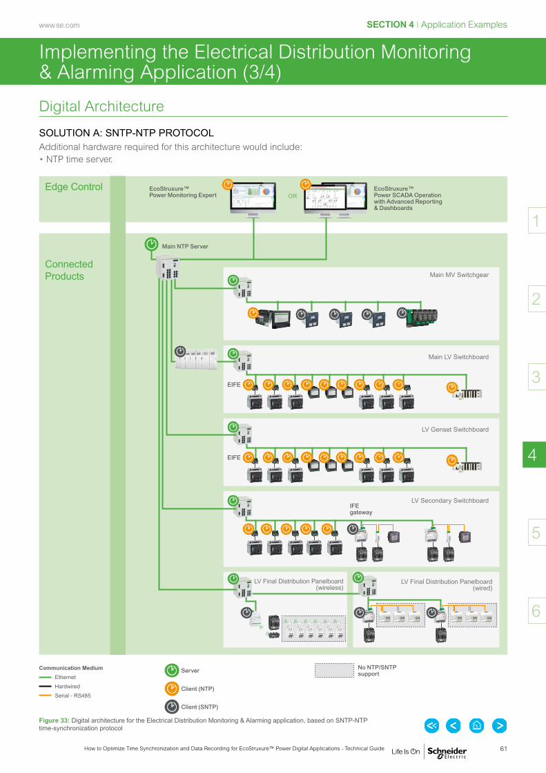
61
SECTION 4 I Application Examples
How to Optimize Time Synchronization and Data Recording for EcoStruxure™ Power Digital Applications - Technical Guide
www.se.com
2
3
5
6
4
1
(3/4)
Server
Client (NTP)
Client (SNTP)
Implementing the Electrical Distribution Monitoring & Alarming Application
Digital Architecture
SOLUTION A: SNTP-NTP PROTOCOLAdditional hardware required for this architecture would include:• NTP time server.
Edge Control
Connected Products
Communication MediumEthernetHardwiredSerial - RS485
EcoStruxure™ Power Monitoring Expert OR
EcoStruxure™ Power SCADA Operation with Advanced Reporting & Dashboards
Figure 33: Digital architecture for the Electrical Distribution Monitoring & Alarming application, based on SNTP-NTP time-synchronization protocol
Main MV Switchgear
Main LV Switchboard
EIFE
LV Genset Switchboard
EIFE
LV Secondary SwitchboardIFE gateway
LV Final Distribution Panelboard (wireless)
Main NTP Server
LV Final Distribution Panelboard (wired)
No NTP/SNTP support

62
SECTION 4 I Application Examples
How to Optimize Time Synchronization and Data Recording for EcoStruxure™ Power Digital Applications - Technical Guide
www.se.com
2
3
5
6
4
1
(4/4)Implementing the Electrical Distribution Monitoring & Alarming Application
Digital Architecture (cont.)
SOLUTION B: SYNCHRONIZATION OVER MODBUS / IONNo additional hardware required for this architecture.
Edge Control
Connected Products
Communication MediumEthernetHardwiredSerial (antenna cable)
EcoStruxure™ Power Monitoring Expert OR
EcoStruxure™ Power SCADA Operation with Advanced Reporting & Dashboards
Figure 34: Digital architecture for the Electrical Distribution Monitoring & Alarming application, based on time-synchronization over Modbus / ION
Main MV Switchgear
Main LV Switchboard
EIFE
LV Genset Switchboard
EIFE
LV Secondary SwitchboardIFE gateway
LV Final Distribution Panelboard (wireless)
LV Final Distribution Panelboard (wired)
Device cannot be synchronizedMaster
Slave

63
SECTION 4 I Application Examples
How to Optimize Time Synchronization and Data Recording for EcoStruxure™ Power Digital Applications - Technical Guide
www.se.com
2
3
5
6
4
1
(1/3)Implementing the Cost Allocation Application
Data to Be RetrievedWith the help of the implementation section (Section 3) of the EcoStruxure™ Power Digital Application Design Guide, we can define what data needs to be retrieved in the different parts of the installation and which key equipment will provide it.
MV
MV/LV
LV
Loads
Main MV switchgear
LV Genset switchboard
Main LV switchboard A
Secondary DSB A
Final DSB A1
Final DSB A1
Utility 1 Utility 2 (Backup)
Genset,DG1
Genset,DG2
Genset,DG3
UPS A2
UPS A1
Main LV switchboard B
Secondary DSB B
Final DSB B1
Final DSB B2
UPS B2
UPS B1
MV/LV TRA_A
MV/LV TRA_B
Figure 35: Data to be retrieved for the Cost Allocation application and associated devices
Easergy P3
PowerLogic ION9000
MasterPact MTZ
PowerLogic PM8000
Electrical Measurements From Utilities and the ED Network• Current, voltage, energy• Power (Active, Reactive, Apparent)• Frequency• Power factor• Harmonic distortion• Voltage and current unbalance
PowerLogic PM5000
PowerLogic PowerTag NSX
PowerLogic PowerTag
ComPact NSX
ComPact NSX
Acti9 iEM3000
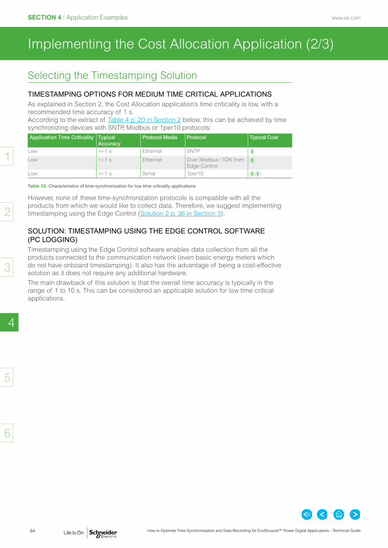
64
SECTION 4 I Application Examples
How to Optimize Time Synchronization and Data Recording for EcoStruxure™ Power Digital Applications - Technical Guide
www.se.com
2
3
5
6
4
1
(2/3)Implementing the Cost Allocation Application
Selecting the Timestamping Solution
TIMESTAMPING OPTIONS FOR MEDIUM TIME CRITICAL APPLICATIONSAs explained in Section 2, the Cost Allocation application’s time criticality is low, with a recommended time accuracy of 1 s. According to the extract of Table 4 p. 20 in Section 2 below, this can be achieved by time synchronizing devices with SNTP, Modbus or 1per10 protocols:Application Time Criticality Typical
AccuracyProtocol Media Protocol Typical Cost
Low +/-1 s Ethernet SNTP
Low +/-1 s Ethernet Over Modbus / ION from Edge Control
Low +/-1 s Serial 1per10
Table 12: Characteristics of time-synchronization for low time criticality applications
However, none of these time-synchronization protocols is compatible with all the products from which we would like to collect data. Therefore, we suggest implementing timestamping using the Edge Control (Solution 2 p. 36 in Section 3).
SOLUTION: TIMESTAMPING USING THE EDGE CONTROL SOFTWARE (PC LOGGING)Timestamping using the Edge Control software enables data collection from all the products connected to the communication network (even basic energy meters which do not have onboard timestamping). It also has the advantage of being a cost-effective solution as it does not require any additional hardware.The main drawback of this solution is that the overall time accuracy is typically in the range of 1 to 10 s. This can be considered an applicable solution for low time critical applications.

65
SECTION 4 I Application Examples
How to Optimize Time Synchronization and Data Recording for EcoStruxure™ Power Digital Applications - Technical Guide
www.se.com
2
3
5
6
4
1
(3/3)Implementing the Cost Allocation Application
Master clock
Slave
Digital Architecture
Solution: Timestamping using the Edge Control Software (PC Logging)Timestamping using the Edge Control software requires no specific additional hardware apart from the classical communication network:
Edge Control
Connected Products
Communication MediumEthernetHardwiredSerial (antenna cable)
EcoStruxure™ Power Monitoring Expert OR
EcoStruxure™ Power SCADA Operation with Advanced Reporting & Dashboards
Figure 36: Digital architecture for Cost Allocation application implementation, implementing timestamping using the Edge Control
Main MV Switchgear
Main LV Switchboard
LV Secondary Switchboard
LV Final Distribution Panelboard (wireless)
LV Final Distribution Panelboard (wired)

66
SECTION 4 I Application Examples
How to Optimize Time Synchronization and Data Recording for EcoStruxure™ Power Digital Applications - Technical Guide
www.se.com
2
3
5
6
4
1

Connected Products ............................................................ p. 68
Edge Control ........................................................................ p. 76
APPENDIX
Product Information

68 How to Optimize Time Synchronization and Data Recording for EcoStruxure™ Power Digital Applications - Technical Guide
www.se.comAPPENDIX I Product Information
2
3
4
6
5
1
Connected Products (1/8)
PROTECTION, MONITORING & CONTROL DEVICES
Easergy P5Medium voltage network protection relay
Easergy P5 is a range of protection relays for demanding medium voltage applications. It offers users dedicated features for industry-leading protection relay functionality to reduce risks and improve reliability, all with advanced connectivity.
Easergy P3Medium voltage network protection relay
Easergy P3 is a range of easy-to-use protection relays for medium voltage applications. With fast delivery, it is ideal for saving panel builders, contractors and partners time. Easergy P3 has been designed to meet customer's needs including overcurrent and arc flash protection and latest connectivity.
Easergy Sepam SeriesMedium voltage network protection relay
Sepam series has all the functionalities required for protecting MV substations, transformers, busways as well as LV distribution, capacitor banks and motors, and for managing gensets. If a problem occurs, clear and complete information is provided to make the right decision immediately. Sepam can be used in the harshest environments, including off-shore oil rigs and chemical factories.
Easergy T300Distribution network management for MV and LV applications
Easergy T300 is a modular platform for hardware and firmware, and an application building block for medium voltage and low voltage distribution network management. It offers a single solution for control and monitoring, from a simple pole-top device to a large MV/LV substation. It is a powerful Remote Terminal Unit for feeder automation.
MasterPact MTZ High current air circuit breakers up to 6300 A embedding advanced digital technologies for LV applications
Future Ready Masterpact MTZ is a comprehensive range of air circuit breakers designed to protect electrical systems from damage caused by overloads, short circuits and equipment ground faults. Masterpact MTZ embeds advanced digital technologies and Micrologic X control units help contribute to safety and energy efficiency.
MasterPact NWHigh current air circuit breakers up to 6300 A for LV applications
Masterpact NW is a comprehensive range of air circuit breakers designed to protect electrical systems from damage caused by overloads, short circuits and equipment ground faults. The embedded Micrologic control unit contributes to safety and energy efficiency. The range covers ratings from 800 to 6300 A in two different sizes.
MasterPact NTHigh current air circuit breakers from 800 to 1200A for LV applications
MasterPact NT is a range of air circuit breakers designed to protect electrical systems from damage caused by overloads, short circuits and equipment ground faults

69How to Optimize Time Synchronization and Data Recording for EcoStruxure™ Power Digital Applications - Technical Guide
www.se.com APPENDIX I Product Information
2
3
4
6
5
1
Connected Products (2/8)
PROTECTION, MONITORING & CONTROL DEVICES (cont.)
ComPact NSMolded case circuit breakers from 630 to 3200 A for LV applications
ComPact NS is a range of molded case circuit breakers (MCCB) with embedded MicroLogic control units for built-in power & energy metering. The solution covers ratings from 630 to 3200 A. It offers built-in power and energy metering in addition to electrical measurement and analysis functions. The solution can be used to deliver a source changeover switch function (TransferPact). It can also evolve with the installation, with interchangeable trip units that combine protection and measurement, as well as standardised accessories.
ComPact NSXMolded case circuit breakers up to 630 A for LV applications
Compact NSX is a full range of high performance molded case circuit breakers in 2 frame sizes designed to meet your needs from thermal-magnetic to advanced Micrologic trip units. Micrologic allows for wired communication, or Powertag NSX is designed for wireless communication.
PowerLogic VampArc flash protection system
PowerLogic Vamp is a range of ultra-fast and flexible arc flash protection products which help eliminate or minimize the costs resulting from arc flash damages -- downtime, repair time, interruption of processes and equipment. PowerLogic Vamp helps avoid personal injury due to arc flash events.
Vigilohm IM20-HInsulation monitoring device (IMD) for hospital applications
Vigilohm IM20-H is a specific Insulation Monitoring Device (IMD) that complies with IEC 61557-8 and provides insulation integrity alarming, isolation transformer overload and temperature monitoring. The communication protocol is Modbus RTU.
Vigilohm IMD IFL12HInsulation fault locator (IFL) for Hospital application
Vigilohm IMD IFL12H is a digital Insulation Fault Locator (IFL) for low-voltage ungrounded power systems. When installed in conjunction with an IM20-H, this insulation fault locator individually monitors each of the feeders. It reports fault locations, either locally, through a light and a contact, or remotely, through the Modbus communication port.
INSULATION MONITORING & FAULT LOCATION DEVICES

70 How to Optimize Time Synchronization and Data Recording for EcoStruxure™ Power Digital Applications - Technical Guide
www.se.comAPPENDIX I Product Information
2
3
4
6
5
1
Connected Products (3/8)
PowerLogic ION9000 seriesPower quality meters for utility incomers or highly critical applications
PowerLogic ION9000 series is a range of advanced power quality meters, designed for high-accuracy, energy cost, network management and power quality requirements.
PowerLogic PM8000 seriesPower quality meters for critical applications
PowerLogic PM8000 series is a range of high-performance power meters for cost and network management applications on feeders and critical loads. It simplifies power quality, and maximizes versatility.
PowerLogic PM5000 seriesPower meters with basic power quality functionality
PowerLogic PM5000 series is a range of high-end, cost effective and compact power meters which enable energy cost and basic network management applications.
Acti9 iEM3000 seriesEnergy meters (DIN rail-mounting)
Acti9 IEM3000 series is a range of cost effective energy meters which can easily be integrated into an Energy Management System or a Building Management System thanks to native Modbus, BACnet, M-bus and LON protocols. It provides a full view of energy consumption and multiple tariffs give customers the flexibility to match the billing structure of their utility.
PowerTag Energy by PowerLogicEnergy sensors
PowerTag Energy is a range of wireless energy sensors that provide precise, real-time data on energy, currents, power, voltage, and power factor. These sensors accurately monitor energy consumption and wirelessly communicate this data in real-time via a gateway.
POWER METERS

71How to Optimize Time Synchronization and Data Recording for EcoStruxure™ Power Digital Applications - Technical Guide
www.se.com APPENDIX I Product Information
2
3
4
6
5
1
Connected Products (4/8)
Modicon M580Ethernet Programmable Automation Controller (ePAC) & safety PLC for process, availability & safety solutions
Modicon M580 high-end ePAC features redundant controllers, new stand-alone safety controllers (safety PLC) with native Ethernet, and cybersecurity embedded in its core.
ERT Module for Modicon M580 ePACTime stamp module for Ethernet Programmable Automation Controller (ePAC)
The ERT (BMXERT1604) module for the Modicon M580 ePAC features all the characteristics of a regular 16-channel discrete input module. In addition, the ERT module has a time stamping function which records the change (rising or falling edge) of each input channel. To optimize the precision of time stamps, the module is able to receive timecodes from a GPS or DCF77 receiver.
Modicon M340Mid range PLC for industrial process and infrastructure
Modicon M340 Programmable Automation Controller (PAC) is built to suit the needs of the process industry and a wide range of demanding automation applications such as a multitasking system for optimal reflex time.
Substation Monitoring Device (SMD)Local and/or remote monitoring for MV applications
The Substation Monitoring Device performs analytics on temperature and environmental data for monitoring and alarming via a local HMI or SCADA system. The Condition Monitoring Device consists of an M251 PLC and optional Magelis HMI. It is configured in the factory and automatically integrates with Edge Control Software. The SMD can also send SMS messages in case of alarms. The optional colour display provides SLD representation with overlaid temperature values.
PLC & PAC
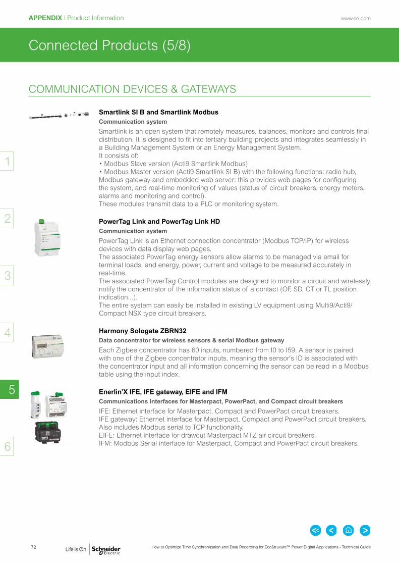
72 How to Optimize Time Synchronization and Data Recording for EcoStruxure™ Power Digital Applications - Technical Guide
www.se.comAPPENDIX I Product Information
2
3
4
6
5
1
Connected Products (5/8)
Smartlink SI B and Smartlink ModbusCommunication system
Smartlink is an open system that remotely measures, balances, monitors and controls final distribution. It is designed to fit into tertiary building projects and integrates seamlessly in a Building Management System or an Energy Management System. It consists of: • Modbus Slave version (Acti9 Smartlink Modbus) • Modbus Master version (Acti9 Smartlink SI B) with the following functions: radio hub, Modbus gateway and embedded web server: this provides web pages for configuring the system, and real-time monitoring of values (status of circuit breakers, energy meters, alarms and monitoring and control). These modules transmit data to a PLC or monitoring system.
PowerTag Link and PowerTag Link HDCommunication system
PowerTag Link is an Ethernet connection concentrator (Modbus TCP/IP) for wireless devices with data display web pages. The associated PowerTag energy sensors allow alarms to be managed via email for terminal loads, and energy, power, current and voltage to be measured accurately in real-time. The associated PowerTag Control modules are designed to monitor a circuit and wirelessly notify the concentrator of the information status of a contact (OF, SD, CT or TL position indication...). The entire system can easily be installed in existing LV equipment using Multi9/Acti9/Compact NSX type circuit breakers.
Harmony Sologate ZBRN32Data concentrator for wireless sensors & serial Modbus gateway
Each Zigbee concentrator has 60 inputs, numbered from I0 to I59. A sensor is paired with one of the Zigbee concentrator inputs, meaning the sensor's ID is associated with the concentrator input and all information concerning the sensor can be read in a Modbus table using the input index.
Enerlin’X IFE, IFE gateway, EIFE and IFMCommunications interfaces for Masterpact, PowerPact, and Compact circuit breakers
IFE: Ethernet interface for Masterpact, Compact and PowerPact circuit breakers. IFE gateway: Ethernet interface for Masterpact, Compact and PowerPact circuit breakers. Also includes Modbus serial to TCP functionality. EIFE: Ethernet interface for drawout Masterpact MTZ air circuit breakers. IFM: Modbus Serial interface for Masterpact, Compact and PowerPact circuit breakers.
COMMUNICATION DEVICES & GATEWAYS

73How to Optimize Time Synchronization and Data Recording for EcoStruxure™ Power Digital Applications - Technical Guide
www.se.com APPENDIX I Product Information
2
3
4
6
5
1
Connected Products (6/8)
Enerlin'X Link150Ethernet gateway
Link150 is a gateway for simple, cost-effective serial-to-Ethernet connectivity. It provides fast, reliable Ethernet connectivity in the most demanding applications, from single building to multi-site enterprises. It supports power and energy meters, circuit monitors, protective relays, trip units, motor controls and other devices that need to communicate data quickly and efficiently. It provides simple, cost-effective serial line to full Ethernet connectivity.
ConneXiumEthernet TCP/IP managed Switch
The ConneXium range offers a smart and flexible way to integrate Ethernet solutions, from the device level to the control network and to the corporate network.
COMMUNICATION DEVICES & GATEWAYS (cont.)

74 How to Optimize Time Synchronization and Data Recording for EcoStruxure™ Power Digital Applications - Technical Guide
www.se.comAPPENDIX I Product Information
2
3
4
6
5
1
Connected Products (7/8)
AccuSine PCS+Active harmonic filter for industrial applications
AccuSine PCS+ is a high performance, scalable active power correction solution for stabilizing electrical networks by providing harmonic mitigation, power factor correction and load balancing.
AccuSine PCSnActive harmonic filter for commercial buildings, the lighting industry and other less harsh environments
AccuSine PCSn series is built on the AccuSine+ platform, providing a scalable and flexible, high performance active harmonic filtering solution capable of mitigating neutral harmonic currents to bring reliability and efficiency to your electrical system, resulting in increased uptime, greater operational efficiency, prolonged equipment life, and improved energy efficiency.
AccuSine PFV+Electronic reactive current compensation for specific and high performance applications
AccuSine PFV+ addresses power quality issues by simple, effective elimination of leading or lagging power factor and reduction of voltage fluctuations. Its unique design helps enhance equipment operating life and improves system power performance, and offers multiple features in one complete package. Power Factor correction with AccuSine PFV+ is worry-free and there is no risk of resonance.
VarSet LV with PowerLogic VarPlus LogicLV capacitor bank
Varset LV is complete range of high quality power factor correction solutions is engineered to compensate reactive power and harmonic distortion. These are easy and flexible solutions that can immediately boost a facility’s energy efficiency and productivity. Thanks to VarSet, your power factor is maintained at an ideal level for optimal power system efficiency and cost reduction.
Galaxy VS3-phase uninterruptible power supply (UPS)
Galaxy VS is a highly efficient 3-phase UPS from 20 to 100kVA (400V/480V) and 10 to 50kVA (208V) for edge, small, and medium data centres and other business-critical applications.
Galaxy VM3 phase uninterruptible power supply (UPS)
Galaxy VM is a 3 phase UPS power protection that seamlessly integrates into medium data centers, industrial or facilities applications.
Galaxy VX3 phase uninterruptible power supply (UPS)
Galaxy VX is a scalable, high-performance extension of the Galaxy V-Series solutions. It is designed for large data centers and industrial applications.
POWER QUALITY MITIGATION, POWER FACTOR CORRECTION & UPS DEVICES

75How to Optimize Time Synchronization and Data Recording for EcoStruxure™ Power Digital Applications - Technical Guide
www.se.com APPENDIX I Product Information
2
3
4
6
5
1
Connected Products (8/8)
Cyber Sciences CyTime SER 2408 / 3200Sequence of events recorder for high time accuracy applications
CyTimeTM SER2409/3200 record status changes of 32 channels, timestamped to 1 ms. Time-synchronization is achieved via PTP (IEEE 1588), IRIG-B, DCF77, NTP, Modbus TCP or an RS-485 signal from another SER. One CyTime SER serves as PTP master and all other CyTime SER devices sync automatically within 100 microseconds—without special Ethernet switches. https://www.cyber-sciences.com/product/sequence-of-events-recorder-ser/
Easergy TH110Wireless thermal sensor for critical connections
The Easergy TH110 is a battery-free wireless temperature sensor used to perform the continuous thermal monitoring of critical connections made in the field, such as: • MV Cable connections• MV Busbar connections• Withdrawable CB connections• MV transformer input, windings, taps, LV output
Easergy CL110Wireless thermal sensor for ambient temperature
The Easergy CL110 is a wireless temperature and humidity sensor with a battery for continuous ambient temperature monitoring: • LV Busway junctions and tap-offs• Internal to electrical switchgear
DATA LOGGERS
SENSORS

76 How to Optimize Time Synchronization and Data Recording for EcoStruxure™ Power Digital Applications - Technical Guide
www.se.comAPPENDIX I Product Information
2
3
4
6
5
1
Edge Control
EcoStruxure™ Power Monitoring ExpertPower Management software
EcoStruxure™ Power Monitoring Expert helps maximize system reliability and optimize operational efficiency to increase your profitability.
EcoStruxure™ Power SCADA OperationHigh performance SCADA software system for electrical distribution monitoring and control
With its high availability, redundancy, high speed data acquisition and alarming, it is aimed at very large sites with many devices and high availability requirements. The software gives operators exceptional knowledge and control of their network through an intuitive, interactive and customizable interface. With fast, consistent access to actionable information, Power SCADA Operation operators are more effective at protecting and optimizing their electrical distribution network, improving both its efficiency and productivity.
EcoStruxure™ Power SCADA Operation with Advanced Reporting & DashboardsHigh performance SCADA software system for electrical distribution monitoring and control with historical dashboards and reporting applications
Advanced Power Monitoring Expert reporting and dashboards embedded in Power SCADA Operation.
SOFTWARE

Reference Documents ......................................................... p. 78
Useful Documentation ......................................................... p. 79
Bibliography

78 How to Optimize Time Synchronization and Data Recording for EcoStruxure™ Power Digital Applications - Technical Guide
www.se.comBIBLIOGRAPHY
2
3
4
5
6
1
Reference Documents
The following documentation has been consulted to create this technical guide:
• Cyber Sciences Technical Notes www.cyber-sciences.com
- “Hi-Res Time Synchronization in Modern Power Systems Using PTP IEEE 1588)” (ref. TN100) - “Overview of IRIG-B Time Code Standard” (ref. TN-102) - “Overview of DCF77 Time Protocol” (ref. TN-103) - “Overview of 1per10 Time Protocol” (ref. TN-104)
• Oralia Technical Note www.orolia.com
- “Differences Between NTP and SNTP” (ref. TN06-101)
• Schneider Electric Application Note www.se.com
- “Time Synchronization and Protection and Control” by Henri Grasset (ref. 998-2095-02-01-19AR0_EN)
• EndRun Technologies White Paper www.endruntechnologies.com
- “Precision Time Protocol (PTP/IEEE-1588)” (ref. PTP-1588)

79How to Optimize Time Synchronization and Data Recording for EcoStruxure™ Power Digital Applications - Technical Guide
www.se.com BIBLIOGRAPHY
2
3
4
5
6
1
Useful Documentation
Design GuideDigital Applications for Large Buildings and Critical Facilities
The Digital Applications Design Guide provides comprehensive details on the building blocks of EcoStruxure Power: the IoT applications are driven by a software layer to control the traditional electrical distribution infrastructure. Developed to help engineering consultants and designers, this guide is an invaluable resource for specifying, designing and prescribing EcoStruxure Power architectures capable of performing one or more of the business-driven applications described within.
IEC EcoStruxure™ Power Design Guide Ref: ESXP2G001EN 12/2019https://go.schneider-electric.com/WW_201903_Digital-Applications-for-Large-Buildings-and-Critical-Facilities-A09116_EA-LP-EN.html?source=Advertising-Online&sDetail=Digital-Applications-for-Large-Buildings-and-Critical-Facilities-A09116_WW
System GuidesEcoStruxure™ Power Monitoring Expert 2020
Power Monitoring Expert system design, deployment and usage.
System Guide Ref: 7EN02-0426-00 PowerMonitoringExpertSysGuide 09/2018
https://www.se.com/en/download/document/PowerMonitoringExpertSysGuide/
EcoStruxure™ Power SCADA Operation 2020 with Advanced Reporting and Dashboards
Power SCADA Operation system design, deployment and usage.
System Guide Ref: 7EN02-0432-00 PowerSCADAOperationSystemGuide 09/2018
https://www.se.com/en/download/document/PowerSCADAOperationSystemGuide/

CO2 and P&L impact through… Resource PerformanceGreen Premium brings improved resource efficiency throughout an asset’s lifecycle. This includes efficient use of energy and natural resources, along with the minimization of CO2 emissions.
Cost of ownership optimization through… Circular PerformanceWe’re helping our customers optimize the total cost of ownership of their assets. To do this, we provide IoT-enabled solutions, as well as upgrade, repair, retrofit, and remanufacture services.
Peace of mind through… Well-being PerformanceGreen Premium products are RoHS and REACh compliant. We’re going beyond regulatory compliance with step-by-step substitution of certain materials and substances from our products.
Improved sales through… DifferentiationGreen Premium delivers strong value propositions through third-party labels and services. By collaborating with third-party organizations we can support our customers in meeting their sustainability goals such as green building certifications.
Discover what we mean by green
Check your products!
An industry leading portfolio of offers delivering sustainable value
Green PremiumTM
More than 75% of our product sales offer superior transparency on the material content, regulatory information and environmental impact of our products:
• RoHS compliance• REACh substance information• Industry leading # of PEP’s*• Circularity instructions
The Green Premium program stands for our commitment to deliver customer valued sustainable performance. It has been upgraded with recognized environmental claims and extended to cover all offers including Products, Services and Solutions.
*PEP: Product Environmental Profile (i.e. Environmental Product Declaration)

www.se.com
81How to Optimize Time Synchronization and Data Recording for EcoStruxure™ Power Digital Applications - Technical Guide
The Schneider Electric brand and any registered trademarks of Schneider Electric Industries SAS referred to in this guide are the sole property of Schneider Electric SA and its subsidiaries. They may not be used for any purpose without the owner's permission, given in writing. This guide and its content are protected, within the meaning of the French intellectual property code (Code de la propriété intellectuelle français, referred to hereafter as "the Code"), under the laws of copyright covering texts, drawings and models, as well as by trademark law. You agree not to reproduce, other than for your own personal, non-commercial use as defined in the Code, all or part of this guide on any medium whatsoever without Schneider Electric's permission, given in writing. You also agree not to establish any hypertext links to this guide or its content. Schneider Electric does not grant any right or license for the personal and non-commercial use of the guide or its content, except for a non-exclusive license to consult it on an "as is" basis, at your own risk. All other rights are reserved.Electrical equipment should only be installed, operated, serviced and maintained by qualified personnel. No responsibility is assumed by Schneider Electric for any consequences arising out of the use of this material.As standards, specifications and designs change from time to time, please ask for confirmation of the information given in this publication.
Legal information
Table of ContentsBack
Previous Page
Next Page

82 How to Optimize Time Synchronization and Data Recording for EcoStruxure™ Power Digital Applications - Technical Guide
www.se.com
Notes

83How to Optimize Time Synchronization and Data Recording for EcoStruxure™ Power Digital Applications - Technical Guide
www.se.com
Notes

11/2019 ESXP2TG001EN
©2019 Schneider Electric. All Rights Reserved. Life Is On Schneider Electric is a trademark and the property of Schneider Electric SE, its subsidiaries and affiliated companies. All other trademarks are the property of their respective owners.
Schneider Electric Industries SAS
35, rue Joseph MonierCS 3032392506 Rueil Malmaison Cedex France
RCS Nanterre 954 503 439Share capital € 896 313 776www.se.com
As standards, specifications, and designs change from time to time, please ask for confirmation of the information given in this publication.