Embed Size (px)
Citation preview

How to make Firmware Updates over LoRaWANPossible
Khaled AbdelfadeelSchool of Computer Science and IT
University College CorkCork, Ireland
Tom Farrell and David McDonaldDanalto
Dublin, [email protected]
Dirk PeschSchool of Computer Science and IT
University College CorkCork, Ireland
Abstract—Embedded software management requirements dueto concerns about security vulnerabilities or for feature updatesin the Internet of Things (IoT) deployments have raised the needfor Firmware Update Over The Air (FUOTA). With FUOTA’ssupport, security updates, new functionalities, and optimizationpatches can be deployed with little human intervention to em-bedded devices over their lifetime. However, supporting FUTOAover one of the most promising IoT networking technologies,LoRaWAN, is not a straightforward task due to LoRaWAN’slimitations that do not provide for data bulk transfer such asa firmware image. Therefore, the LoRa Alliance has proposednew specifications to support multicast, fragmentation, and clocksynchronization, which are essential features to enable efficientFUOTA in LoRaWAN. In this paper, we review these newspecifications and evaluate the FUOTA process in order toquantify the impact of the different FUOTA parameters in termsof the firmware update time, the device’s energy consumption,and the firmware update efficiency, showing different trade-offsamong the parameters. For this, we developed FUOTASim, asimulation tool that allows us to determine the best FUOTAparameters.
Index Terms—LoRaWAN, FUOTA, Clock Synchronization,Multicast, Fragmentation
I. INTRODUCTION
Firmware Update Over The Air (FUOTA) defines the pro-cess of updating a device’s firmware over a wireless medium.This is a crucial feature for large-scale wireless sensor networkinstallations as it allows to deploy security, optimization,and/or new-functionality patches without much human inter-vention in order to protect devices, extend their lifetime and/orenhance their performance [1]. In LoRaWAN [2], FUOTA iseven a more critical requirement because of the long devicelifetime that LoRaWAN promises, e.g., 10 years [3]. This longlifetime stands in contradiction to the fast-changing modernsoftware life-cycle and the LoRaWAN standard, which is sub-ject to continued development. Therefore, FUOTA represents away to keep LoRaWAN devices up-to-date with the standardthroughout their lifetime, which important for reliable, safeand secure long-term operation.
The nature of FUOTA requires downloading a big block ofdata (e.g. a few hundreds of kilobytes) to the devices. This isa challenging task in LoRaWAN because of the limitations ofthe communications technology itself [4]. LoRaWAN is lowdata-rate technology, offering at most a few 10s of kbits/s.LoRaWAN also operates in the unlicensed sub-GHz band,
where transmissions have to obey a duty cycle restriction, forinstance, 1% in Europe. In this case, a device/gateway has tobe silent for at least 99 times the last transmission time aftereach transmission. In addition to that, LoRaWAN is designedfor applications with predominantly uplink transmissions. Forinstance, a downlink transmission, in case of a class-A de-vice, is only available after an uplink transmission. All theselimitations challenge efficient FUOTA over LoRaWAN.
In order to better understanding the impact of LoRaWANlimitations on FUTOA, let us consider how to transmit afirmware image of 50 kBytes using DR2 (SF10/ 125 kHz).Even if the maximum packet size (i.e. 51 bytes for DR2) isused, about 1004 downlink packets are required to transmitthe whole firmware. For this, a similar number of uplinktransmissions is required to solicit the downlink transmissions.Even with a perfect wireless channel with no losses, thefirmware update would take ca. 17 hours to upgrade only onedevice because of the 1% duty cycle limitation. Consequently,updating a medium-size deployment could take up to a fewweeks, which is not practical.
The above example points to a number of features that arerequired for LoRaWAN in order to support efficient FUOTA:
• A mechanism to send downlink transmissions withoutthe need for uplink transmissions to be sent first. Thisoptimizes the devices’ duty cycle and, thus, their powerconsumption.
• Multicast support in order to optimize the gateways’duty cycle by sending downlink transmissions to multipledevices simultaneously.
• A mechanism to download a big data block and recoverpacket losses without congesting the medium with trans-missions to request the missing packets.
For this, the LoRa Alliance, the industry body behind the Lo-RaWAN standard, created the FUOTA working group to definethe baseline needs to enable efficient FUOTA over LoRaWAN.This has resulted in new specifications to cover multicast,fragmentation and time synchronization topics, which areessential features for efficient FUOTA.
In this paper, we describe these new LoRaWAN specifi-cations and examine how the new features can enable fastand efficient firmware update. Additionally, we analyze theproposed FUOTA process in order to quantify the impactof the different parameters and show the trade-offs among
arX
iv:2
002.
0873
5v1
[cs
.NI]
20
Feb
2020

TABLE ILORAWAN REGIONAL PARAMETERS IN EUROPE
Data Configu- Max App Default DutyRate rations Payload Channels Cycle0 SF12/125KHz 51 bytes1 SF11/125KHz 51 bytes 868.10MHz (U/D) 1%2 SF10/125KHz 51 bytes 868.30MHz (U/D) 1%3 SF9/125KHz 115 bytes 868.50MHz (U/D) 1%4 SF8/125KHz 222 bytes 869.525MHz (D) 10%5 SF7/125KHz 222 bytes
Fig. 1. LoRaWAN Classes of operations
them. In order to analyse the process, we developed a newsimulation tool, FUOTASim, to study the FUOTA process.FUOTASim can support LoRaWAN operators to determine thebest parameters when performing FUOTA. To the best of ourknowledge, this work is the first scientific paper that considersFUTOA over LoRaWAN, which is one of the most challengingnetworks for over the air software updates.
II. PRELIMINARIES
This section highlights some of the LoRaWAN features inaddition to the new specifications, which have been developedto support efficient FUOTA.
A. LoRaWAN
LoRaWAN [2], [4], [3] defines the Medium Access Control(MAC) rules, the system architecture, and regional parametersfor operation in different regions of the world. In this work,we consider the regional parameters for Europe as shown inTable I. LoRaWAN supports six data rates (i.e. configuredby the spreading factor and the bandwidth), thanks to itsunique modulation, called LoRa [5]. LoRaWAN operates inthe EU863-870 ISM band, and by default, three channels(868.10, 868.30, and 868.50 MHz) with 1% duty cycle aresupported for uplink and downlink transmissions in addition toone channel (869.252 MHz) with 10% duty cycle for downlinktransmissions.
LoRaWAN supports three classes of operation, namely A, B,and C, where each class offers different downlink capabilitiesto suit a range of IoT applications as shown in Fig. 1. Uplinktransmissions in LoRaWAN follow a simple ALOHA protocol,where devices transmit whenever they have data to transmitas long as the duty cycle permits it and without performingany sort of listen-before-talk policy.
Class A is the mandatory profile that all LoRaWAN deviceshave to support. In this class, each uplink transmission isfollowed by two receive windows at specific times. Downlinktransmissions are only allowed at the beginning of these re-ceive windows. The downlink transmission in the first windowis performed using the same configurations (i.e. data rate andchannel) as the previous uplink transmission. However, a fixedconfigurations, i.e., DR0 (SF12/125KHz) on 869.525 MHz isused in the second window. On the contrary, class C permitsdownlink transmissions all the time except when the devicestransmit. This is done by extending the second receive windowuntil the next uplink transmission, resulting in huge powerconsumption as devices remain in a receive mode for most ofthe time.
Class B allows more receive windows than class A butwithout the huge power consumption of class C. Besides thetwo regular receive windows after each uplink transmission,extra periodic receive windows, called ping slots, are openedat synchronized times. The synchronization is guaranteed byreceiving the gateway beacons that are sent periodically every128 secs. The usable time period between two beacons iscalled beacon window and it is divided into 212 = 4096ping slots of 30 ms each numbered from 0 to 4095. Theping slot periodicity, pingPeriod, of a device is defined using0.96×2p secs, where 0 <= p <= 7. For a certain periodicityp, the assigned number of ping slots in a beacon windowis defined using 27−p. In case of p = 0, a device opens128 ping slots, one slot almost every 1 sec. In case ofp = 7, only one ping slot is opened every 128 secs, whichis the maximum supported ping slot period. In order to avoidsystematic collisions, pingOffset is calculated at the beginningof each beacon period to indicate the time of the first ping slot.pingOffset is a randomised offset, whose values can range from0 to (27−p − 1).
B. Key Requirements of FUOTA
The FUOTA working group defined the baseline needs toperform FUOTA over LoRaWAN. These needs have beendescribed in new specifications that we highlight here. Theobjective of the new specifications (mutlicast, fragmentation,and clock synchronization) is to standardize this essentialprocess, leading to an interoperable FUOTA solution. It isworth mentioning that the new specifications are not part ofthe LoRaWAN MAC but run at the application layer.
Fig. 2 shows the recommended FUOTA architecture [6],where interfaces with solid lines are described in the LoRa Al-liance specifications, otherwise, they are out of the LoRa spec-ifications scope. The architecture shows the network serverin the middle, which handles the communication betweenLoRaWAN devices and application servers. In addition to that,the network sever manages the multicast, including creation,deletion and/or editing of multicast groups and assures deliveryof multicast downlink transmissions to all devices in a group.This is performed by calculating the minimum set of gatewaysthat have to send the same multicast transmission to coverall devices in a group. Firmware update server (right-handside) together with the firmware update management initiate
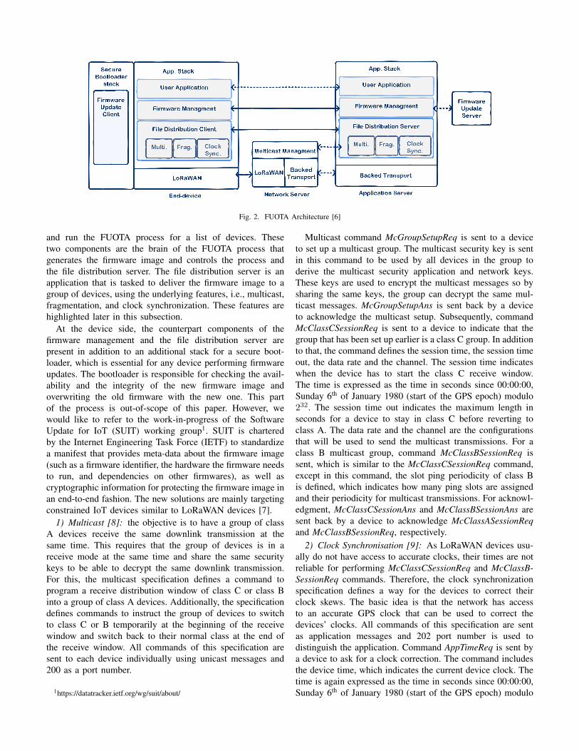
Fig. 2. FUOTA Architecture [6]
and run the FUOTA process for a list of devices. Thesetwo components are the brain of the FUOTA process thatgenerates the firmware image and controls the process andthe file distribution server. The file distribution server is anapplication that is tasked to deliver the firmware image to agroup of devices, using the underlying features, i.e., multicast,fragmentation, and clock synchronization. These features arehighlighted later in this subsection.
At the device side, the counterpart components of thefirmware management and the file distribution server arepresent in addition to an additional stack for a secure boot-loader, which is essential for any device performing firmwareupdates. The bootloader is responsible for checking the avail-ability and the integrity of the new firmware image andoverwriting the old firmware with the new one. This partof the process is out-of-scope of this paper. However, wewould like to refer to the work-in-progress of the SoftwareUpdate for IoT (SUIT) working group1. SUIT is charteredby the Internet Engineering Task Force (IETF) to standardizea manifest that provides meta-data about the firmware image(such as a firmware identifier, the hardware the firmware needsto run, and dependencies on other firmwares), as well ascryptographic information for protecting the firmware image inan end-to-end fashion. The new solutions are mainly targetingconstrained IoT devices similar to LoRaWAN devices [7].
1) Multicast [8]: the objective is to have a group of classA devices receive the same downlink transmission at thesame time. This requires that the group of devices is in areceive mode at the same time and share the same securitykeys to be able to decrypt the same downlink transmission.For this, the multicast specification defines a command toprogram a receive distribution window of class C or class Binto a group of class A devices. Additionally, the specificationdefines commands to instruct the group of devices to switchto class C or B temporarily at the beginning of the receivewindow and switch back to their normal class at the end ofthe receive window. All commands of this specification aresent to each device individually using unicast messages and200 as a port number.
1https://datatracker.ietf.org/wg/suit/about/
Multicast command McGroupSetupReq is sent to a deviceto set up a multicast group. The multicast security key is sentin this command to be used by all devices in the group toderive the multicast security application and network keys.These keys are used to encrypt the multicast messages so bysharing the same keys, the group can decrypt the same mul-ticast messages. McGroupSetupAns is sent back by a deviceto acknowledge the multicast setup. Subsequently, commandMcClassCSessionReq is sent to a device to indicate that thegroup that has been set up earlier is a class C group. In additionto that, the command defines the session time, the session timeout, the data rate and the channel. The session time indicateswhen the device has to start the class C receive window.The time is expressed as the time in seconds since 00:00:00,Sunday 6th of January 1980 (start of the GPS epoch) modulo232. The session time out indicates the maximum length inseconds for a device to stay in class C before reverting toclass A. The data rate and the channel are the configurationsthat will be used to send the multicast transmissions. For aclass B multicast group, command McClassBSessionReq issent, which is similar to the McClassCSessionReq command,except in this command, the slot ping periodicity of class Bis defined, which indicates how many ping slots are assignedand their periodicity for multicast transmissions. For acknowl-edgment, McClassCSessionAns and McClassBSessionAns aresent back by a device to acknowledge McClassASessionReqand McClassBSessionReq, respectively.
2) Clock Synchronisation [9]: As LoRaWAN devices usu-ally do not have access to accurate clocks, their times are notreliable for performing McClassCSessionReq and McClassB-SessionReq commands. Therefore, the clock synchronizationspecification defines a way for the devices to correct theirclock skews. The basic idea is that the network has accessto an accurate GPS clock that can be used to correct thedevices’ clocks. All commands of this specification are sentas application messages and 202 port number is used todistinguish the application. Command AppTimeReq is sent bya device to ask for a clock correction. The command includesthe device time, which indicates the current device clock. Thetime is again expressed as the time in seconds since 00:00:00,Sunday 6th of January 1980 (start of the GPS epoch) modulo

232. Next, the device gets AppTimeAns back, including thetime correction that stipulates the time delta correction in secs.The expected accuracy of this approach is around one second,which is enough to run the multicast commands efficiently .
3) Fragmentation [10]: A firmware image is usually quitebig (i.e. a few hundreds kBytes), which cannot fit in onedownlink packet but needs quite a number of packets. Inaddition to that, LoRaWAN links are lossy and there is noway to know which packets are lost at which devices duringmulticast transmissions. Therefore, a mechanism to handle bigdata blocks and to recover packet losses in a scalable manneris required. For this, the fragmentation specification supportsall necessary commands to transport a large data block to onedevice or to a group of devices reliably if multicast class Cor class B is used. All commands of this specification aresent as application messages and port number 201 is used todistinguish this application.
Command FragSessionSetupReq is sent to a device todefine a fragmentation session. The command specifies whichmulticast groups are allowed as input for this fragmentationsession. In addition to the number of fragments, the fragmentsize, the fragmentation algorithm (recovery algorithm), andthe padding size are specified. The padding size is used asthe firmware image may not be an integer multiple of thefragmentation size. A device sends FragSessionSetupAns backto acknowledge setting up the fragmentation session.
At the time of writing of this paper, only one fragmentationalgorithm was defined. The algorithm proposes adding asimple forward error correction code to the original firmwareimage before sending it. This allows devices to autonomouslyrecover a certain ratio (based on the code used) of the losttransmissions without requesting re-transmission of lost frag-ments. This is done by, first, chunking the original firmwareimage to fragments equal in size and then adding redundancyfragments, which are XORed to some of the original frag-ments. Devices can use redundant fragments to reconstructtheir missing fragments. For example, 5% redundancy addedto the original firmware image allows devices to loose roughly5% of the incoming transmissions and still be able to recon-struct the original firmware.
III. FUOTA PROCESS
The FUOTA process is initiated at the firmware updateserver, which generates the new firmware fragments alongwith the redundant fragments. Also, together with the firmwaremanagement, the firmware update server assures that therequired sessions (mutlicast, fragmentation and etc.) are al-ready established at the intended devices before sending thefragments. The firmware update server takes system decisionswhich affect the efficiency of the process. These decisionsinclude the topology of the multicast group(s), the class of themulticast (i.e. C or B), the data rate and the channel to be usedto transmit the multicast fragments. For example, the firmwareupdate server may decide to divide a big group of devices intotwo smaller groups and run two FUOTA sessions in parallelinstead of running one FUOTA session. The questions that
Fig. 3. FUOTA Session using class C multicast
arises is whether this decision would make the update anymore efficient?
Although the LoRa Alliance tries to standardize the FUOTAprocess by defining the new specifications, the FUOTA routineitself is not standardized and open for contributions. In thissection, we present a straightforward FUOTA routine that doesnot convey any kind of smartness. Nevertheless, the proposedFUOTA routine can help us to study and evaluate the processand define the trade-offs in the system design. This can helpLoRaWAN operators understand the impact of their systemdecisions on the process’ efficiency and, thus, can help themto devise smarter FUOTA processes.
Let us consider a firmware update is scheduled for aLoRaWAN deployment, consisting of class A devices. Con-sequently, the firmware update server configures the samemulticast and fragmentation sessions for all devices. An ex-ample of the FUOTA session that uses mutlicast class C isshown in Fig. 3. It should be noted that the multicast andthe fragmentation requests are downlink commands and, thus,uplink messages are needed first in order for the devicesto open receive windows. Once these two sessions are setup, every device sends AppTimeReq command to ask forclock correction before the firmware update server can set upthe start time of the multicast transmissions. The start timehas to be sufficiently far in the future to guarantee that alldevices have set up the required sessions before sending themulticast transmissions. For the multicast class B group, thecorresponding commands are used as shown in §II-B1.
At the exact declared time, all devices must switch toclass C and open a continued receive window based on theconfigurations (data rate and channel) that have been sent inthe McClassCSessionReq command. At the same time also, thefirmware update server schedules the firmware fragments one

TABLE IISIMULATION PARAMETERS
Parameters Value [Unit] + CommentRandom Seeds 10Devices 100 - 500Rx1 Window same configurations as previous uplinkRx2 Window DR0 and 869.252 MHz (10% DC)Data Rate Distribution [DR0→6%, DR1→8%, DR2→8%,
DR3→11%, DR4→22%, DR5→45%]Gateway Receptions 8 in parallelLoRaWAN MAC Header 8 [Bytes]Path Loss [11] near (< 400m, d0 = 92.67,
PLd0 = 128.63, γ = 1.05, σ = 8.72)far (≥ 400m, d0 = 37.27,PLd0 = 132.54, γ = 0.8, σ = 3.34)
Devices Antenna Gain 2.2 dBmGateways Antenna Gain 8 dBmApplication Uplinks 15 [Bytes]Multicast Transmissions 869.252 MHz (10% DC)Redundant Fragments 30Capacity of Batteries 1000 [mAh], 11100 [Joules]Power Consumption 132 [mW] (Transmission)
48 [mW] (Reception)0.018 [mW] (Ideal)
after another until all the fragments, including the redundantones, have been sent. Once a device receives enough fragmentsto reconstruct the firmware image, it reverts back to classA. It should be noted that all transmissions, either uplink ordownlink are governed by the duty cycle limitations of thechannel used. Following the complete download, an integritycheck is done on the received image (details are out-of-scope)and the image is marked as ready if the check is passed. Next,the old firmware is replaced with the new one (details are out-of-scope), which completes the firmware update.
IV. PERFORMANCE EVALUATION
To evaluate the FUTOA process, we developed a simulationtool, called FUOTASim, which leverages the Simpy packagefor process-based discrete-event simulation in Python. FUO-TASim implements the dual-component log-distance pathlossmodel from [11], which was fitted to real LoRaWAN mea-surements. FUOTASim also considers the packet error modelthat was presented in [12], which draws on a probabilisticreception model based on the signal strength and packetlength. In addition to that, FUOTASim adopts some featuresfrom FREESim [12] such as the impact of the imperfectorthogonality of spreading factors and the duty cycle limi-tations, leading to realistic simulation results. Finally, FUO-TASim simulates the FUOTA process as described in §IIIwith varying parameter settings. The settings allow choosingbetween multicast class C or class B to perform FUOTA. Inthe case of class B, a parameter to configure the ping slotperiodicity is presented. In addition to that, FUOTASim allowsthe use of different data rates, firmware sizes, fragment sizes,and redundant codes to perform FUOTA. The aforementionedfeatures are required for a proper evaluation of the FUOTAprocess, making FUOTASim a useful tool for the LoRaWANcommunity2.
2https://github.com/kqorany/FUOTASim
100 200 300 400 500(a) Number of Devices
0
50
100
150
200
250
300
350
Leng
th in
Tim
e [m
ins]
Total TimeStart Time
100 200 300 400 500(b) Number of Devices
0
2
4
6
8
10
Ener
gy C
onsu
mpt
ion
[J]
Fig. 4. Initial Phase - Time Required and Energy Consumption
The simulation campaigns consider one gateway that isplaced in the middle of a LoRaWAN deployment. Class A Lo-RaWAN devices are spatially distributed around that gatewayin such a way so as to acquire a certain data rate distributionacross the deployment. We aim for a data rate distribution suchthat 45% of the devices use DR5 (SF7/125KHz), 22% use DR4(SF8/125KHz), 11% use DR3 (SF9/125KHz), 8% use DR2(SF10/125KHz), 8% use DR1 (SF11/125KHz), and finally 6%use DR0 (SF12/125KHz). This distribution is obtained froma real LoRaWAN deployment in Dublin, Ireland, making ourresults more realistic. Table II summarizes all the simulationparameters used in the evaluations. Each simulated studyis executed 10 times using different random seeds and themean across all results is presented along with the standarddeviation.
The simulations are divided into two phases: initial andmulticast to show the impact of each phase separately. Theinitial phase covers everything required before the multicasttransmissions can be sent. From Fig. 3, the initial phase coversthe multicast session setup, the fragmentation session setup,the clock synchronization, and the class C session start. How-ever, the multicast phase covers the multicast transmissions.The evaluation results are presented in terms of the followingmetrics:
• energy consumption, which indicates the average device’senergy consumption.
• time, which indicates the average time required to finisha certain task.
• update efficiency, which indicates the average ratio ofdevices that receive the firmware image successfully.
A. Initial Phase Study
In this phase, we investigate the device’s energy consump-tion (see Fig. 4b) and the total time required (see Fig. 4a (TotalTime)) for the devices to go through the initial phase. Fig. 4bshows a linear increase in the device’s energy consumptionover the network size, where the energy consumption increasesby approx. 2 Joules with every 100 devices added to thenetwork. A similar trend is observed between the total time andthe network size (see Fig. 4a (Total Time)). Fig. 4a presentsalso the start time metric, which indicates the minimum timerequired for the devices to complete only the class C session

100 200 300 400 500(a) Number of Devices
0
1
10
100
1 kNu
mbe
rs p
er D
evice
nrUplinksnrDownlinks
100 200 300 400 500(b) Number of Devices
0
10
20
30
40
50
60
Rate
of O
verh
ead
UplinkDownlink
Fig. 5. Initial Phase - Uplinks vs Downlinks
100 200 300 400 500(a) Number of Devices
0
1
10
100
1 k
Num
bers
per
Dev
ice
nrUlostnrCollisionsnrNoDown
100 200 300 400 500(b) Number of Devices
0
1
2
3
4
5Ra
te o
f Inc
reas
e
nrUlostnrCollisionsnrNoDown
Fig. 6. Initial Phase - Source of Losses in Uplink Transmissions
start as in Fig. 3. The start time in McClassCSessionReqcommands has to be sufficiently far in the future to guaranteethat every device receives a McClassCSessionReq commandand acknowledges the command’s receipt. In Fig. 4a, the starttime metric indicates the earliest time for the firmware updateserver to start the multicast transmissions. If the start timeis set to be less than the shown results, some devices maymiss their McClassCSessionReq commands and, thus, missthe multicast transmissions. The metric is shown in minutes,where the reference time is the time of sending the firstMcClassCSessionReq command ever during the initial phase.The linear increase is also observed here between the starttime metric and the network size.
End-devices throughout the initial phase rely on the Lo-RaWAN MAC (i.e. simple Aloha), which is known for its poorscalability, which is even worse when downlink transmissionsare required [13]. This is the main reason behind the linearincreasing trend we observed in the energy and the timemetrics (see Fig. 4). In order to quantify the impact of thescalability issue, Fig. 5a shows the average number of uplinkand downlink transmissions per device throughout the initialphase. In the case of no losses and no duty cycle limitations,only 7 uplink and 4 downlink transmissions are required foreach device (see Fig. 3). However, in real conditions, thenumber of uplink transmissions increases significantly (seeFig. 5a). For instance, in a network with 100 devices, a devicesends approx. 94.7 uplink transmissions, which equals approx.12.5 times more overhead (see Fig. 5b). With increasing thenetwork size, the overhead increases linearly for the uplinktransmissions (see Fig. 5b). For the downlink transmissions,
(a)0
50
100
150
200
Frag
. Size
[Byt
e]
DR0DR1DR2DR3DR4DR5
(b)0.0
0.5
1.0
1.5
2.0
2.5
Air T
ime
[Sec
]
DR0DR1DR2DR3DR4DR5
Fig. 7. Airtime and size of fragments per data rates
5K 10K 50K 100KFirmware Sizes [Bytes]
0
500
1 k
1.5 k
2 k
Num
ber o
f Fra
gmen
ts
DR0DR1DR2
DR3DR4DR5
Fig. 8. Number of Fragments
the losses are very low because of no collisions and the highantenna gain of the gateways.
Fig. 6a shows the different sources behind the huge numberof uplink transmissions and Fig. 6b shows the rate of increasein reference to a network size with 100 devices. The mainsources of loss are a) collisions (nrCollisions) b) loss dueto channel fading (nrUlost) c) gateway’s duty cycle limita-tion (nrNoDown). nrNoDown metric indicates the numberof uplink transmissions of a device that has been receivedcorrectly by the gateway but the gateway could not transmitthe corresponding downlink (in the two receive windows) dueto the duty cycle limitation. In this case, a re-transmission isscheduled. Surprisingly, the collisions are not the main sourceof loss as it only presents 0.3% of the losses. This is due to therelatively small network sizes considered in our simulations.For bigger network sizes, the collisions would be a serioussource of losses [12]. The channel fading also has a minimalimpact on the losses, about 1.9%. However, the main source ofloss is the duty cycle limitation of the gateway (nrNoDown),which presents about 97.8% of the losses. This is a veryimportant conclusion that has to be considered when designingthe FUOTA routine. More insights are presented in §V.
B. Multicast Transmissions Phase Study
In this subsection, we study the impact on time, energyconsumption, and efficiency of the varying configurable pa-rameters for the multicast fragments during the firmware
update. These parameters include the data rate used, the classof multicast, either C or B, and the ping periodicity in case ofclass B. Besides these parameters, we study the impact of thefirmware sizes on the aforementioned metrics by consideringdifferent sizes: 5kBytes, 10kBytes, 50kBytes, and 100kBytesbytes. As this phase includes only downlink transmissions, thenetwork size does not impact much on the results. Therefore,the presented results are gathered only from a network sizewith 100 devices, where results can be generalized to the othernetwork sizes.
The fragment size is both directly and inversely proportionalto the update time and, thus, the device’s energy consumption.On one hand, longer fragment sizes reduce the overall numberof fragments, however, the fragments would have a higherprobability of error, requiring more redundant fragments. Onthe other hand, shorter fragment sizes reduce the probabilityof error but increase the ratio of MAC header (overhead)to payload size, resulting in high overhead. This trade-offhas been studied theoretically in [12] to compute the bestpacket/fragment size per data rate. Although the calculationshave been done for an uplink use case, the conclusion holdstrue for the downlink as well. The calculations concluded thatthe impact of packet errors is not as critical as the impactof the MAC header overhead in terms of time and energyconsumption. Therefore, long packets for all data rates arebetter than short packets to reduce the overall number oftransmissions and, thus, the impact of MAC headers.
For this reason, the fragment sizes are set to equal themaximum MAC payload sizes (see Table. I). Fig. 7 showsthe fragment sizes and the airtimes (i.e. transmission times)of one fragment. A clear observation is that the lower thedata rate, the higher the airtime even for the same fragmentsize. For instance, the fragment sizes at DR5 and DR4 are thesame but the airtime at DR5 is almost half the airtime at DR4.This is due to the positive relationship between the spreadingfactor and the airtime [14]. The fragment sizes also determinethe number of fragments (see Fig. 8). These numbers alongwith the airtimes (see Fig. 7b) and the duty cycle limitationsaffect the firmware update time. Therefore, increasing the datarate, one would expect an increase in the update time and thedevice’s energy consumption. Nevertheless, increasing the datarate, one would also expect an increase in the update efficiencyas higher data rates have longer transmission ranges (i.e. lowersensitivity). This trade-off is quantified later in this subsection.
1) Multicast Class C: Fig. 9a shows the update time acrossall data rates and for different firmware sizes. Furthermore,Fig. 9b shows the rate of increase in terms of the data ratesand the firmware sizes in reference to DR0 and firmware sizeof 5kbytes, respectively. The time metric almost doubles withevery time the firmware doubles in size. In addition to that, forthe same firmware size, the time metric among the data ratesshows the same relationship, showing almost 30 times higherwhen using DR0 than using DR5. This is mainly due to thelarge number of fragments and the long airtime in the case ofDR0, resulting in long silent periods between two successivetransmissions due to the duty cycle of the gateway.
Fig. 10a shows the device’s energy consumption and Fig. 9b
5K 10K 50K 100K(a) Firmware Size [Bytes]
0
200
400
600
800
1 k
Tim
e to
Upd
ate
[min
s]
DR0DR1DR2
DR3DR4DR5
5K 10K 50K 100K(b) Firmware Size [Bytes]
0.0
2.5
5.0
7.5
10.0
12.5
15.0
17.5
Rate
of I
ncre
ase
0 1 2 3 4 5Data Rates
0
5
10
15
20
25
30
35
Rate
of I
ncre
ase
Fig. 9. Class C - Time to Update
5K 10K 50K 100K(a) Firmware Size [Bytes]
0
500
1 k
1.5 k
2 k
2.5 k
Ener
gy C
onsu
mpt
ion
[J]
DR0DR1DR2
DR3DR4DR5
5K 10K 50K 100K(b) Firmware Size [Bytes]
0.0
2.5
5.0
7.5
10.0
12.5
15.0
17.5
Rate
of I
ncre
ase
0 1 2 3 4 5Data Rates
0
5
10
15
20
25
30
35
Rate
of I
ncre
ase
Fig. 10. Class C - Energy Consumption
5K 10K 50K 100KFirmware Size [Bytes]
0.00
0.25
0.50
0.75
1.00
1.25
1.50
Upda
te E
fficie
ncy
DR0DR1DR2
DR3DR4DR5
Fig. 11. Class C - Update Efficiency
shows the rate of increase in terms of the data rates andthe firmware sizes. We can observe that Fig. 10b is almostidentical to Fig. 9b. This is because energy consumption isproportional to the devices’ receiving time. In multicast classC, a device is always in a receive mode for the whole time ofthe update.
From Fig. 9 and Fig. 10 it can be observed that for a certainfirmware size, the higher the data rate, the lower the updatetime and the lower the devices’ energy consumption. Never-theless, another factor has to be considered when choosing thedata rate, which is the update efficiency. This is because of thefact that the higher the data rate, the shorter the transmissionrange and, thus, the lower the update efficiency. Fig. 11 showsthe update efficiency using all data rates and for different

0 1 2 3 4 5 6 7(a) Periodicity
0
50
100
150
200
Tim
e to
Upd
ate
[min
s]Firmware Size = 5K
DR0DR1DR2
DR3DR4DR5
0 1 2 3 4 5 6 7(b) Periodicity
0
5
10
15
20
25
Rate
of I
ncre
ase
Firmware Size = 5KDR0DR1DR2
DR3DR4DR5
Fig. 12. Class B - Time to Update
firmware sizes. Using DR0, all devices can be updated at oncecompared to only 45% of the devices in the case of usingDR5. The update efficiency metric is directly proportional tothe considered data rate distribution (see Table. II). Theseresults highlight that more than one FUOTA session wouldbe required in the case of using DR5 to update all devices.This would still be acceptable because of the long time and thehigh energy required in the case of using DR0 (30 times higherthan DR5) (see Figs. 9 and 10). However, this is subject to thedistribution of gateways in the deployment or their mobility,where a gateway may be able to move to reach more devicesevery time, e.g., a drone based gateway.
2) Multicast Class B: The presented results here are froma firmware image of size 5kbytes only and the results ofthe other sizes can be roughly estimated using the rate ofincrease from class C (see Fig. 9b). Fig. IV-B1a shows theupdate time using all data rates and all ping slot periodicities.Furthermore, Fig. IV-B1b shows the rate of increase of all datarates in reference to ping periodicity p = 0. As shown, p = 0is the best ping periodicity for all data rates as it achievesthe lowest update time. This is because of the abundanceof ping slots (128 slots) available when p = 0, which doesnot limit the downlink transmissions. The results of p = 1are close enough to the results of p = 0. This is becausethese two ping periodicities are still lower than the duty cycleof the gateway. However, for higher ping periodicities, thetime metric increases proportionally to the corresponding pingperiodicity. An increase of 17% is observed in the time metriccompared to the results of class C. The reason behind thisincrease is that the downlink transmissions of class B areperformed at the beginning of the ping slots only. In this case,even if the duty cycle of the gateway permits to transmit anew downlink fragment, the transmission has to wait until thebeginning of the next ping slot, which prolongs the overallupdate time.
Fig. IV-B2a shows the device’s energy consumption usingall data rates and all ping periodicities. The energy consump-tion is directly proportional to the devices’ receiving time. Inclass B, the radio of a device is in a receive mode only whenreceiving downlink fragments, receiving gateway beacons,and checking empty ping slots. Otherwise, the radio of adevice is in idle mode. The gateway beacons are received tokeep the synchronization with the gateway’s clock. Checkingempty ping slots happens when a ping slot is assigned for
0 1 2 3 4 5 6 7(a) Periodicity
0.0
0.1
0.2
0.3
0.4
0.5
Ener
gy C
onsu
mpt
ion
[J]
Firmware Size = 5KDR0DR1DR2
DR3DR4DR5
0 1 2 3 4 5 6 7(b) Periodicity
0.3
0.2
0.1
0.0
0.1
0.2
Rate
of I
ncre
ase
Firmware Size = 5KDR0DR1DR2
DR3DR4DR5
Fig. 13. Class B - Energy Consumption
the multicast session but the gateway could not transmit inthis slot due to the limited duty cycle. In this case, devicesstay in a receive mode at the beginning of the empty slotsfor the time of a packet preamble. Fig. IV-B2b shows therate of increase of all data rates in terms of the device’senergy consumption in reference to ping periodicity p = 0.It is clear that p = 0 is not the best periodicity anymore.However, the energy consumption decreases with increasingthe periodicity until a certain periodicity, where afterward theenergy consumption starts to increase again. This is becauseof the relationship between the ping slot periodicity and thegateway’s duty cycle. If the periodicity is lower than thegateway’s duty cycle, devices check a lot of empty ping slots,resulting in high energy consumption. Also, if the periodicityis higher than the gateway’s duty cycle, devices have to receivea lot of gateway beacons to keep synchronization, resulting inhigh energy consumption as well. The best scenario is to havea periodicity close enough to the gateway’s duty cycle. Asthe gateway’s duty cycle depends on the data rate used, thebest periodicity varies with the data rate. From Fig. IV-B2b,p = 5 is found to be the best for DR0, p = 4 for DR1,p = 3 for DR2, p = 3 for DR3, p = 3 for DR4, and p = 2for DR5. Considering the best periodicity for each data rate,Class B presents a massive reduction in the device’s energyconsumption up to 550 times less compared to class C.
V. DISCUSSION
Here we discuss some ideas as to how to optimize theFUOTA process for different scenarios. We also provide somefurther insights based on the above simulation results.
A. Initial Phase
The initial phase is a prerequisite stage every time afirmware update is to be deployed and, therefore, approachesto reduce its overhead in terms of time and energy con-sumption are desirable. An efficient approach is particularlydesirable for frequent small firmware updates such as securitypatches whereby the overhead of the initial phase can bemuch higher than transmitting the firmware update itself. Oursimulation results showed that the main source of the overheadis the duty cycle limitation of the gateway. An approach toovercome this might be to use multiple co-located gateways,where the overall overhead can be reduced as the network willhave higher duty cycle to handle the downlink transmissions

as multiple gateways can be used in parallel. The overhead canbe also reduced by minimizing the number of transmissionsduring the initial phase. This can be achieved by combiningmultiple commands (e.g., multicast setup and fragmentationsetup command) in one command and the gateway can ac-knowledge both commands with just one packet.
Another overhead reduction mechanism might be to pre-program the devices with the required multicast and fragmen-tation session information before or during deployment intothe field as part of the commissioning stage. In this case, thetime synchronization and the multicast start will be the onlycommands required during the initial phase.
B. Multiple Gateways for Collaborative FUOTA
The rate at which multicast fragments of the firmware canbe transmitted is limited by the duty cycle of the gateway.This limitation leads to prolonged firmware update times,which may not be acceptable for certain applications as thenormal device operation is blocked during the update time.Consequently, mechanisms to expedite the multicast transmis-sions are beneficial. Multiple co-located gateways would be ahelpful approach here as well, where the gateways transmit themulticast fragments in a collaborative mechanism. In the caseof multicast class C, the gateways can transmit the fragmentsin a round-robin fashion, taking advantage of those devicesthat are in a continued receive mode. Consequently, the updatetime is shortened proportional to the number of the gatewaysused. For example, using ten gateways in a round-robin fashionwould achieve an overall 100% duty cycle (each gatewaytransits in the 10% duty cycle channel).
In the case of multicast class B, a new multicast sessionis required every time an additional gateway is used whentransmitting the fragments. Here, each gateway handles theping slots of one multicast session and devices wake up toreceive all fragments from all gateways. The drawback here isthat this adds additional overhead to the initial phase unlessthese sessions are pre-programmed into the devices beforedeployment.
C. Network Architecture Planning
Using a higher data rate to transmit the firmware fragmentsis always better in terms of time and energy consumptioncompared to using a lower data rate. However, in the casewhere firmware updates are transmitted through only onegateway, the simulation results showed that this negativelyaffects the update efficiency, where lower data rates achievebetter coverage and thus better update efficiency than higherdata rates. This trade-off can be settled completely towardshigh data rates in the case of the multiple gateways scenario.If gateways are geographical distributed such that all devicescan be reached when using one of the high data rates,we can achieve the shortest update time, the lowest energyconsummation, and the maximum update efficiency all at thesame time.
However, network architecture planning is usually not donefrom a network management point of view such as FUOTA buttypically from an application point of view in order to achieve
required performance metrics, such as high packet deliveryratio. Nevertheless, network architecture planning based onthe requirements for network management would be beneficialwhen the rate of FUOTA is expected to be high. An examplewould be where a LoRaWAN deployment is initially basedonly on a minimal viable application but over time is upgradedto support a wider range of features. LoRaWAN operatorstake this approach to expedite their position in the market bydeploying their network initially with limited applications andrelying on FUOTA to extend and optimize applications overtime. In this case, FUOTA sessions could be expected to bescheduled more frequently than usual, e.g., once a month.
The cost of deploying enough gateways in order for alldevices to be reached using one of the high data rates could behigh, especially for the vast deployments. In this case, using amobile gateway could be a reasonable approach. In particular,the deployment is divided geographically to small segments,where if the mobile gateway is deployed in the middle ofa segment, the devices within that segment can be reachedusing the desired data rate. Consequently, the gateway movesfrom one segment to another to update the devices within eachsegment. This approach is backed by our simulation resultsthat showed gains in terms of time and energy using similarapproaches. For example, running approx. 30 FUOTA sessionsusing the highest data rate is still more beneficial than runningone FUOTA using the lowest data rate.
VI. RELATED WORK
The need for FUOTA has been recognized since the earlydays of Wireless Sensor Networks (WSNs) whereby the de-ployment scale and the often remote and inaccessible locationsof devices were the main drivers behind this need [15].Consequently, a lot of research has been carried out, coveringdifferent aspects of the firmware update, including protocolsfor disseminating the update, reducing the size of the update,and executing the update on the devices [16].
The protocols developed for disseminating the firmwareupdate in WSNs are based mainly on the underlying networkarchitecture and protocol stack. In [17], the firmware updateis disseminated through multiple paths in multi-hop WSNs.While in [18], the update is targeting network stack modulesto reconfigure the network on the fly. The Message QueuingTelemetry Transport (MQTT) protocol is used to disseminatethe firmware updates to a fleet of WiFi devices in [19]. ForWSNs that enable end-to-end IP connectivity (e.g. 6LoW-PAN [20]), the update can be disseminated using ConstrainedApplication Protocol (CoAP) over UDP [21].
Our work looks at LoRaWAN in contrast to those othernetwork stacks. LoRaWAN does not support the end-to-endIP connectivity and its downlink capability is more limited. Inaddition to that, LoRaWAN’s physical layer supports multiple,quasi-orthogonal data rates and the transmissions are restrictedwith the duty cycle of the sub-Giga ISM band. These limita-tions hinder the adaption of legacy protocols for disseminatingfirmware updates over LoRaWAN. It should be noted thatthe protocols for FUOTA suggested in this work are network

agnostic and, thus, they can be directly adopted in similarnetworks to LoRaWAN such as Sigfox 3.
VII. CONCLUSIONS
FUOTA is a critical requirement for any long-term deploy-ment of LoRaWAN in order to maintain optimal, safe, andsecure operations of the network. In this work, we reviewednew specifications (multicast, fragmentation, and clock syn-chronization) by LoRa Alliance that make efficient FUOTApossible on top of LoRaWAN. We also evaluated a proposedFUOTA process, showing the impact of the different FUOTAparameters on the performance of the proposed process. Thesimulation results showed that the initial phase (required forsetting up the required sessions) is a bottleneck of the wholeprocess as it is not scalable with the network size. The resultsalso showed that multicast class B achieves 17% higher updatetime and 550 times less energy use compared to multicast classC. Additionally, the simulations demonstrated the significantimpact of the data rate used on the overall results. For example,DR5 achieves 30% reduction in update time and device energyconsumption compared to DR0. However, this comes at theexpense of the firmware update efficiency, where DR5 canonly update a portion of the devices (depends on the devices’distribution) every session whilst DR0 can update all devicesat once. The ping slot periodicity p, in case of multicast classB, impacts the results as well. For all data rates, the fastestfirmware update can be done with p = 0, however, in termsof the energy consumption, the optimal periodicity varies withvarying the data rate. In this case, p = 5 is found to be thebest for DR0, p = 4 for DR1, p = 3 for DR2, DR3, and DR4,and p = 2 for DR5.
ACKNOWLEDGMENT
This publication has emanated from research conductedwith the financial support of Science Foundation Ireland (SFI)and is co-funded under the European Regional DevelopmentFund under Grant Number 13/RC/2077.
REFERENCES
[1] Jongboom, Jan and Stokking, Johan, “Enabling firmware updates overLPWANs,” http://janjongboom.com/downloads/ew2018-paper.pdf, 2018,unpublished; Accessed: 2-January-2020.
[2] LoRa Alliance, Technical Committee, “LoRaWAN 1.1 Specification,”lora-alliance.org/sites/default/files/2018-04/lorawantm specification-v1.1.pdf, 2017, online; accessed 30-September-2019.
[3] J. Haxhibeqiri, E. De Poorter, I. Moerman, and J. Hoebeke, “A Survey ofLoRaWAN for IoT: From Technology to Application,” Sensors, vol. 18,no. 11, 2018.
[4] F. Adelantado, X. Vilajosana, P. Tuset-Peiro, B. Martinez, J. Melia-Segui, and T. Watteyne, “Understanding the Limits of LoRaWAN,” IEEECommunications Magazine, vol. 55, no. 9, pp. 34–40, 2017.
[5] Semtech Corporation, “AN1200.22, LoRa Modulation Basics,” www.semtech.com/uploads/documents/an1200.22.pdf, 2015, online; accessed30-September-2019.
[6] FUOTA Working Group of the LoRa Alliance Technical Committee,“FUOTA Process Summary,” https://lora-alliance.org/sites/default/files/2019-04/tr002-fuota process summary-v1.0.0.pdf, 2019, accessed: 2-January-2020.
[7] K. Zandberg, K. Schleiser, F. Acosta, H. Tschofenig, and E. Baccelli,“Secure firmware updates for constrained iot devices using open stan-dards: A reality check,” IEEE Access, 2019.
3https://www.sigfox.com/en
[8] FUOTA Working Group of the LoRa Alliance Technical Committee,“LoRaWAN Remote Multicast Setup Specification,” https://lora-alliance.org/sites/default/files/2018-09/remote multicast setup v1.0.0.pdf, 2018,accessed: 2-January-2020.
[9] FUOTA Working Group of the LoRa Alliance Technical Commit-tee, “LoRaWAN Application Layer Clock Synchronization Speci-fication,” https://lora-alliance.org/sites/default/files/2018-09/applicationlayer clock synchronization v1.0.0.pdf, 2018, accessed: 2-January-2020.
[10] FUOTA Working Group of the LoRa Alliance Technical Com-mittee, “LoRaWAN Fragmented Data Block Transport Specifi-cation,” https://lora-alliance.org/sites/default/files/2018-09/fragmenteddata block transport v1.0.0.pdf, 2018, accessed: 2-January-2020.
[11] K. Q. Abdelfadeel, Y. Samarawickrama, and V. Cionca, “How to conductlorawan site surveys,” in 2019 International Conference on Wirelessand Mobile Computing, Networking and Communications (WiMob), Oct2019, pp. 133–138.
[12] K. Q. Abdelfadeel, D. Zorbas, V. Cionca, and D. Pesch, “Free -fine-grained scheduling for reliable and energy efficient data collection inlorawan,” IEEE Internet of Things Journal, pp. 1–1, 2019.
[13] A.-I. Pop, U. Raza, P. Kulkarni, and M. Sooriyabandara, “Does Bidirec-tional Traffic Do More Harm Than Good in LoRaWAN based LPWANetworks?” in IEEE Global Communications Conference (GLOBE-COM). IEEE, 2017, pp. 1–6.
[14] Semtech Corporation, “LoRa Modem Design Guide,” www.semtech.com/uploads/documents/LoraDesignGuide STD.pdf, 2013, online; ac-cessed 30-September-2019.
[15] S. Brown and C. Sreenan, “Updating software in wireless sensornetworks: A survey,” Dept. of Computer Science, National Univ. ofIreland, Maynooth, Tech. Rep, pp. 1–14, 2006.
[16] S. Brown and C. Sreenan, “Software updating in wireless sensor net-works: A survey and lacunae,” Journal of Sensor and Actuator Networks,vol. 2, no. 4, pp. 717–760, 2013.
[17] J. W. Hui and D. Culler, “The dynamic behavior of a data disseminationprotocol for network programming at scale,” in Proceedings of the2nd international conference on Embedded networked sensor systems.ACM, 2004, pp. 81–94.
[18] T. Zimmermann, J. Hiller, H. Reelfs, P. Hein, and K. Wehrle, “Split:Smart protocol loading for the iot.” in EWSN, 2018, pp. 49–54.
[19] D. Frisch, S. Reißmann, and C. Pape, “an over the air update mechanismfor esp8266 microcontrollers,” in Proc. 12th Int. Conf. Syst. Netw.Commun.(ICSNC), 2017.
[20] Z. Sheng, S. Yang, Y. Yu, A. V. Vasilakos, J. A. McCann, and K. K.Leung, “A survey on the ietf protocol suite for the internet of things:Standards, challenges, and opportunities,” IEEE Wireless Communica-tions, vol. 20, no. 6, pp. 91–98, 2013.
[21] Z. Shelby, K. Hartke, and C. Bormann, “The constrained applicationprotocol (coap),” , 2014.