Embed Size (px)
Citation preview

Inductors and Loading Coil Current (Mobile and Coil Loaded Antennas)
[ Home ] [ Up ] [ Independent Measurements ] [ Inductor operation ] [ Inductor Current Time Delay ]Related pages:
Mobile antenna FS comparisons Loading Inductors Inductor Spice Model
W7EL's Measurements and comments Constructing an RF Current Meter
Time Delay Through Coil
Note: the discussion below primarily deals with loading inductors used in mobile HF antennas rather than long radiating helices. Ifyou read carefully you will see why a long helice behaves more like a radiating transmission line and less like a conventionalinductor. The discussion below also applies to tank coils. It is important to read everything below IN CONTEXT for yourself andnot listen to what other people tell you it says. Some people, for some reason I can't understand, claim it says things that are notactually said. :-). Don't depend on other people's reading skills.
How Does an Inductor orLoading Coil Work? Much of the data below also applies to inductors inequipment, such as tank circuits.
The most common questions are:
What does the coil do? A normal physically small(physically small compared to antenna length or wavelength)loading coil or loading inductor does not replace a missingfraction of a wavelength. A physically small loading coilsimply inserts a series inductive reactance that cancelscapacitive antenna reactance. When a 150-ohm reactanceinductor is inserted in series with a 150-ohm capacitive load(like an antenna) reactances cancel. Only the resistive partsremain.
What determines current distribution in a loadingcoil? Current distribution is determined by straycapacitance to the outside world and the impedanceterminating the loading coil. The current in any inductorwould be equal at each end except for displacement currents.Displacement currents are "imaginary currents" that flowthrough a capacitance. A changing electric field is tied tothese currents.
How much level difference is there in loading coilcurrent entering the coil and loading coil current
exiting the far end? If the antenna beyond the coil has low self-impedance compared to the impedance of stray capacitances thatshunt current from the coil to "ground", currents at each end of the coil will be essentially equal. The current taper effect is notcaused by the "missing antenna length" the coil replaces. Current taper is determined by the ratio of termination impedance to straycapacitance from parts of the coil to surroundings. If the portion of antenna above or beyond the loading coil is long or has a largephysical area compared to the physical size of the coil, coil current will be essentially equal throughout the coil and at each end. Intank circuits, inductor current is equal at each end unless the tank capacitors have a very low value compared to the tank inductor'sstray capacitance to the chassis. This is one reason why we do not want to mount an inductor close to sheet metal.
What does significant current taper in the loading or tank coil indicate? Large differences in end currents on aninductor are strong indicators of poor antenna or tank circuit layout or design. An example would be a situation where a loading coilor tank coil has high stray capacitance to other areas of the system (like the groundplane or surrounding objects) compared to
Mobile antennas, short verticals, loading coil loss,and loading coil current file:///E:/Theory-antenna/w8ji-Mobile-antennas-short verticals.htm
1 von 14 07.07.2014 20:58

capacitive reactance of the system at the high impedance ends of the inductor. Significant current taper indicates poor inductor,layout, or antenna construction or design.
click to view typical installation measurements
The Difference Between a Loading Coil and a Normal Inductor
There really isn't any difference between a loading coil and a conventional inductor or coil used in other systems, except theimpedances and surroundings are different. The inductor or loading coil behaves the same way whether the load is a radiatingantenna or an electronic circuit. An inductor is an inductor, it doesn't change characteristics depending on end-use, although differentdesigns can work better with different reactance and circuit requirements.
Mobile loading coils or loading coils for short antennas often have very high reactance. They often have extremely low capacitanceat one end, and this makes stray capacitance throughout the inductor a concern.
Stray capacitance from turn-to-turn increases circulating currents. Turn-to-turn capacitance increases effective inductance andeffective resistance, yet at the same time unnecessary stray capacitance reduces system bandwidth and (contradictory as this sounds)also reduces effective Q.
Stray capacitance to the outside world causes the coil to behave like an L-network, and transform impedances instead of providing apure series reactance. This is why the optimum form factor of a coil becomes longer compared to the diameter with any inductorhaving very high reactance. This is also why inductors (RF chokes), at high enough frequencies, behave like back-to-back Lnetworks. We call this effect "series resonance" when discussing power amplifier plate chokes.
Inductors with low inductive reactance are much less critical of internal and external stray capacitances. Optimum form-factor in alow reactance inductor leans towards a short coil with the diameter nearly equaling length. In tank circuits, or with loading coils usedwith longer antennas or with capacitance hats, the optimum inductor shape becomes shorter and larger in diameter. In a short mobileantenna or very high impedance tank system or circuit, optimum inductor form factor becomes longer when compared to diameter.Long high inductance coils are generally good, compact large diameter inductors often work better in low inductance ranges.
Most optimized-form air core inductors fall between 1:1 and 4:1 length to diameter ratios, the exact value depending on inductor andterminating reactances. A coil behaves the same way regardless if used as a loading coil or used as a tank inductor.
Common myths about inductor behavior:
One common myth is loading coil current is reduced by standing waves or by the fraction of "electrical degrees" the inductor"replaces" as it passes through the length of wire in the coil. There are two reasons cited for this. One idea is the current isreduced because the loading coil replaces a certain amount of "electrical degrees" of antenna area, substituting or replacingthe normal current taper seen in an unterminated antenna. The other idea is that series loss resistances cause a currentreduction.
We often find inexperienced builders of 5/8th wl antennas think the "loading coil" needs to contain 1/8th wavelength of wire in orderto make the 5/8th wave antenna a "3/4wl resonant antenna". They think, through wire length alone, the wire creates a low feedimpedance by making the antenna three-quarters of a wave long electrically. In other cases claims are made one half-wave of wirewound on a compact form causes a 180-degree current delay, making a compact coil useful for phasing in a collinear array.
The basic flaw is the above ideas do not account for what actually occurs in a coil. The flawed viewpoint is current goes in one end,winds its way around through the physical length of wire in the coil, and after a time delay caused by the copper path length currentappears at the other end. There is a physical mechanism that prevents what we might intuitively think happens from actuallyhappening. A coil or loading inductor has magnetic mutual coupling between turns. The physical mechanism is the magnetic field inthe coil!
What Really Happens
When current flows in the transmitter-end of the coil, a magnetic field is created. This time-varying magnetic field causes charges inthe other turns to instantly move. This effect ripples through the length of the coil at light-speed, just over 186,000 miles per second.As long as the magnetic flux coupling is high, the delay through the coil is the speed of light over the physical length of the coil. In aninductor with good flux coupling from end-to-end, the electrical time delay in current is very close to the physical length of thecoil expressed in degrees at the operating frequency. Note that this time delay is NOT the phase relationship between voltage andcurrent, but the delay time of current appearing at each inductor terminal. More on this appears later in this text.
(Another interesting effect occurs. The increasing magnetic field sets up an "opposing voltage" as it cuts across conductors. Thisopposing voltage, created as the field expands, is what causes the current to rise slower than the applied voltage. If the excitingvoltage is decreased the field collapses, and now the voltage changes polarity and aids current flow! If we don't allow the current toflow, the voltage will rise until it does. This is what causes the kick in a relay coil when we open the relay coil path, or the spark in anignition when the points abruptly open.)
In an RF system, the physical size of the coil actually does add some "antenna effect". For example, on 160 meters the wavelength is
Mobile antennas, short verticals, loading coil loss,and loading coil current file:///E:/Theory-antenna/w8ji-Mobile-antennas-short verticals.htm
2 von 14 07.07.2014 20:58
about 550 feet. 1.5 feet is about one electrical degree. A skinny one foot tall coil, with negligible stray capacitance, would haveabout 0.67 electrical degrees phase delay of current between each terminal. This delay occurs because to coil occupies a physicallength of .67 degrees. Current at each end would be almost perfectly equal, the taper would be about what we would expect for afractional-degree-long coil.
(In the real world, all components have some stray capacitance and flux leakage, so they have a different amount of electricallength and current taper than the "negligible capacitance" case. In good coil designs, the capacitance and leakage is small andcan be ignored. I'll show you measurements later to prove this.)
Now let's look at an extreme case. If the entire antenna is "coiled", like a helically wound antenna with no top hat or stinger, currentwould be reduced to nearly zero at the open end. This is because distributed capacitance over the length of the antenna is fairly high,the shunting capacitance has a low impedance compared to impedance at the end of the antenna, and current is diverted to ground inthe form of displacement currents. The significant displacement current distributed along the coil causes phase delay through thecoil, as well as the current taper along the length.
Compact loading coils are another matter. In many cases phase delay is negligible or immeasurable by normal methods.. providingflux coupling is nearly perfect. A good example would be a relatively compact toroid or a compact nearly-square L/D ratio loadinginductor. I've found it impossible to measure the current taper in a toroid and very difficult to measure in a compact air-core loadingcoil. (The opposite extreme would be be a perfectly straight wire with no folds or bends or the helical antenna described above.)
In the case of the toroid or compact coil, the behavior would be such that doubling the turns nearly perfectly quadruples inductance.If we doubled turns and inductance simply doubled or increased at a much faster rate, we should know the coil is in a mode otherthan a pure inductor mode. This is a strong indicator inductor operating Q is less than optimum, and the inductor might behave lessthan ideally in critical applications.
As a matter of fact, observing inductance change while adding turns can be an excellent test for flaws or shortfalls in system design.A linear increase in inductance when adding conductor length indicates design problems.
A perfect impedance squaring effect indicates minimal electrical phase-delay, or "antenna length" of an inductor. Impedance squaringas turns are doubled indicates the undesired inductor stray capacitance has a high reactance compared to the antenna system beyondthe loading coil. Of course there can be exceptions, but it is a good general rule that large current taper indicates the loading system ismuch less efficient than necessary.
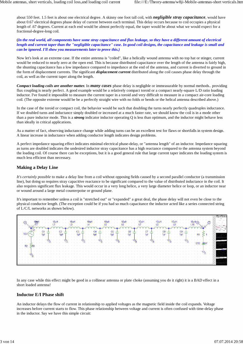
Making a Delay Line
It's certainly possible to make a delay line from a coil without opposing fields caused by a second parallel conductor (a transmissionline), but doing so requires stray capacitive reactance to be significant compared to the value of distributed inductance in the coil. Italso requires significant flux leakage. This would occur in a very long helice, a very large diameter helice or loop, or an inductor nearor wound around a large metal counterpoise or ground plane.
It's important to remember unless a coil is "stretched out" or "expanded" a great deal, the phase delay will not even be close to thephysical conductor length. (The exception could be if you had so much capacitance the inductor acted like a series connected stringof L/C/L networks as shown below).
In any case while this effect might be good in a collinear antenna or plate choke (assuming you do it right) it is a BAD effect in ashort loaded antenna!
Inductor E/I Phase shift
An inductor delays the flow of current in relationship to applied voltages as the magnetic field inside the coil expands. Voltageincreases before current starts to flow. This phase relationship between voltage and current is often confused with time-delay phasein the inductor. Say we have this simple circuit:
Mobile antennas, short verticals, loading coil loss,and loading coil current file:///E:/Theory-antenna/w8ji-Mobile-antennas-short verticals.htm
3 von 14 07.07.2014 20:58

Current and voltage at V1 will be out-of-phase by the effect of L1 "charging" with magnetic flux. Current appears AFTER voltagerises, and falls after voltage falls. Current in R1, however, is exactly in phase with voltage across R1. That's because the voltageacross R1 is always E=I*R.
Every component must follow the Laws or electrical rules established for that component.
The current in R1 is delayed from VOLTAGE rise in V1 by the voltage to current phase delay of L1. This does result in a time delayin relationship to voltage rise at V1, but there is NO current time delay through L1! V1, L1, and R1 all have the same peak current atthe same time!!!
The notion that antenna loading coil delay current by the same time as they delay response to increased voltage is obviouslynonsense.
Here is a graph of phase delays in the above system:
Current in the load, generator, and inductor all exactly track in the same relationship from dc up. There is no "phase delay". Thegenerator voltage is a straight line different than current, and this indicates the generator sees a "reactive load".
This is an ideal model. It does not include shunt capacitance, or flux leakage.
Mobile antennas, short verticals, loading coil loss,and loading coil current file:///E:/Theory-antenna/w8ji-Mobile-antennas-short verticals.htm
4 von 14 07.07.2014 20:58

Phase Shift of Current
What happens to current passing through an inductor with very tight inter-turn flux coupling?
Magnetic flux links the ends of an inductor. Current does not enter one end of the inductor, wind through the turns, and appear with atime delay related to conductor length on the other terminal. The magnetic field travels through the coil at light speed, and when thevery first turn is magnetized every turn linked by the flux immediately has current induced. The delay is related to the speed of lightand physical distance from the starting turn to the ending turn. (This assumes negligible stray capacitance to the outside worldcompared to load impedance.)
Here's a SPICE model of an inductor (this would represent perfect coupling) showing current at three points indicated by A, B, andC:
You can see A, B, and C have thesame current and same phase.This would be true for forwardwaves as well as reflected waves.Of course this is an inductor withperfect mutual coupling and nodisplacement current. A realinductor of reasonable formfactor would have some smallphase delay.
Mobile antennas, short verticals, loading coil loss,and loading coil current file:///E:/Theory-antenna/w8ji-Mobile-antennas-short verticals.htm
5 von 14 07.07.2014 20:58

Phase Shift Of Voltage
Where does the phase delay come in? The voltage at different parts of the system is delayed. Here are voltage waveforms withrespect to ground:
Mobile antennas, short verticals, loading coil loss,and loading coil current file:///E:/Theory-antenna/w8ji-Mobile-antennas-short verticals.htm
6 von 14 07.07.2014 20:58

Spice allows us to show phasedifference between multiplepoints. The graph to the leftshows phase difference at threepoints.
The Misplaced Notion
Proponents of the idea that coils replace "antenna length" and equal the missing antenna length in degrees are unable to define a setof rules or logically demonstrate why a current reduction and "electrical-degree" phase delay directly related to the antenna area"replaced" occurs in a two-terminal component. While a long inductor with poor flux linkage from end-to-end, or an inductor withlow values of stray capacitive reactance to a groundplane compared to series impedance, can cause SOME current inequalities andphase delays, the amount is normally immeasurable with normal thermal current meters when the inductor has good form factor andreasonable termination impedance above the coil. The amount of current taper actually rivals the disturbance of the system byadding the measurement device, unless we construct the measurement device very carefully.
Both W7EL and myself made independent measurements of current in small loaded antennas. These measurements demonstrate the"missing electrical degrees" in an antenna has nothing to do with current distribution in the coil. Some people have actuallyincorrectly reported W7EL's data! Here's what he had to post on rec.radio.amateur.antenna to correct misrepresented claims.
The Need for a Measurement
An article long ago on E-ham claimed measurements proved a new concept about loading coil current. The E-ham article putforth an idea that current disappears as it moves through a loading inductor without a mechanism like displacementcurrents providing a path. This claim conflicts with established component behavior, so it would indeed be fascinating if itwere true! One of the claims supporting the idea that coils in antenna work differently than coils in circuits was that anon-radiating toroid loading inductor showed a current taper when used in an antenna.
I recently constructed a calibrated current meter that slips over whip antennas and masts, and is for all practical purposestotally immune to variations in voltage in the system. It also is mostly plastic, and has minimal effect on stray capacitance ofthe antenna. The resonant frequency and currents are not significantly perturbed by measurements with this meter. When Iadded a similar meter used in the other tests, resonant frequency shifted significantly! This is a sure sign the meter'scapacitance or inductance is affecting the system.
In late December 2003 and early January 2004, I made additional measurements of loading inductor currents. The resultsclearly agree with the analysis that had been presented on this page since early 2003. Without displacement currents,currents into and out of a loading inductor are equal. That is a hard rule, it agrees with theories defined by people muchsmarter than me, and I believe it is unbendable unless the works of Faraday, Maxwell, Ohm, and Kirchhoff were incorrect.
A sample of measurements above and below the loading coil with various antenna above the coil (current as percent ofreference) follow:
Toroid with hatSmall 2x2" coil with 24"hat up 24"
Long 12x3" coil with 24"hat up 24"
Long 12x3"coil with 6'whip
Current below 100% 100 100 100
Current above 100 94.4 73 76%
Mobile antennas, short verticals, loading coil loss,and loading coil current file:///E:/Theory-antenna/w8ji-Mobile-antennas-short verticals.htm
7 von 14 07.07.2014 20:58

Toroid with whiplong 12x1.5" coil with 6'whip
long 12x1.5" coil with24" hat
Small 2x2" coil with 6'whip
Current below 100% 100 100 100
Current above coil 100% 79% 75% 96%
Current in whip 1ftabove top of coil
73%
The most revealing thing was how noticeably small changes in stray capacitance near the middle and top of the loading coilaffect current distribution. It was quite evident hanging a large meter on each end of the coil would greatly perturb thesystem.
Clearly we do NOT want:
A large hat just above a large coilA long large coil and a short whipA coil near large sheetmetal
More data along with photographs will appear on a new page over the next month or so. Until then, I can assure everyone theconventional theories presented below are accurate, and the theory that "electrical length" the coil "replaces" is incorrect.Loading coils indeed behave like any other inductor in the world.
Independent measurements by a reliable engineer have agreed with my measurements above. Anyone doubting my data need onlyread the following e-mail from W7EL.
The Incorrect Assumption
Another commonly misconception is, since voltage increases at the far end of the loading coil, current must logically decrease. Afterall, we have a fixed amount of power and voltage has increased. The assumption is:
1.) We multiply voltage times current to get power.
2.) If voltage increases current must decrease.
Unfortunately, this is not correct in reactive systems! Simple P (power) = I (current) times E (voltage) only works when the system isnon-reactive. This condition only occurs at resonance, and only below the loading coil at the antenna feedpoint!
In a reactive system, like in a mobile whip above a loading coil, voltage and current are no longer in phase. As a matter of fact,voltage and current can closely approach being 90 degrees out-of-phase when the whip is electrically very short. Since the antennaarea above the loading coil is highly reactive (voltage is not in phase with current), we can not multiply voltage times current withoutconsidering phase differences.
You may have heard the term "reactive power" or VAR (volt-amperes-reactive). Reactive power is voltage times current withoutconsideration of phase angle. We can have kilowatts of VAR power with only a low power transmitter, and that is what we actuallyhave in the reactive part of the small antenna.
Coil Q and Changes in Efficiency
Current taper or reduction has been cited as a reason coil "Q" has little effect on signal level in mobile systems. Speculation is onlythe first few turns of the loading coil carry significant current because the coil "leaks" magnetic fields and radiates, and this is whythe coil Q has little effect.
Another idea proposes the loading coil "makes up" a certain missing part of the antenna. It goes on to conclude the loading coil canbe accounted for in "electrical degrees", making up the "missing difference" in antenna degrees. This isn't true either. The inductordoesn't know where it is and suddenly change from "x" ohms reactance to electrical degrees! It responds to AC currents and voltagesas any inductor in any circuit does. It doesn't suddenly change measurement units.
As an example of this, try to define a 45-degree electrical length inductor at 1.8 MHz. That would mean it is a capacitor at 3.61MHz,where it is over 90-degrees long! How many turns at what length and diameter is a 45-degree inductor?? Where is a formula thatallows converting a given size inductor to electrical degrees? This shows how useless and meaningless that definition is!
The inductor adds a certain amount of series reactance, that's all. A 300uH inductor is not 20-degrees long, nor is it 80-degrees long,so far as radiation goes unless it is really that long physically. It is a certain number of ohms reactance at a certain frequency, or acertain number of units called Henries. It is not "electrical degrees" that it adds, it is a non-dissipative reactance (in combination witha loss resistance because of finite quality) at a certain frequency!
A loading inductor can "insert" a large amount of phase shift, but the phase shift is between voltage and current. The only exception
Mobile antennas, short verticals, loading coil loss,and loading coil current file:///E:/Theory-antenna/w8ji-Mobile-antennas-short verticals.htm
8 von 14 07.07.2014 20:58
to this would be if the inductor had considerable distributed shunt capacitance to the outside world, and acted like a string of seriesinductors (with the antenna) and shunt capacitors (shunting to the ground system). In that case we could expect coil Q to beextremely low, since it would be the electrical equivalent of a lossy transmission line. That's either an awful loading coil, or it is aless-efficient helical loaded antenna!
The Correct View
Another group of people don't argue against established and proven circuit theory. They understand charges flowing into one end ofthe loading coil must have someplace to branch off (a virtual third terminal), or they must flow out the other end. Without thatadditional "virtual" path, charges flowing into the coil would always equal charges flowing out. This is true regardless of radiation,losses, or induction fields.
This makes perfect sense when we think of any dc circuit, antenna, or RF system. Electrical rules are satisfied, the system behaves asit does in the real world.
There is very little change in current, unless the coil is physically very long compared to the rest of the antenna above the coil orunless the coil is laid right against "grounded" conductors and the whip above the coil is very short. This fits perfectly with helicalverticals, where the coil is "stretched out" over the length of the antenna.
It also agrees with base loaded antennas, which have nearly as much current into the antenna above the coil as at the feedpoint. Itagrees with center loaded antennas, where current below the coil is essentially uniform and the whip above has triangulardistribution.
Current can be different in various areas of an inductor, but only if shunting capacitances (impedances) to the outside world aresignificant compared to load capacitance (impedance). Another condition where current can vary substantially is with operation nearthe condition of self-resonance in what is normally considered or defined as a "series-resonant" mode. This would be a very poor andinefficient loading inductor, such as when a 160-meter antenna is used at a secondary resonant frequency in upper HF.
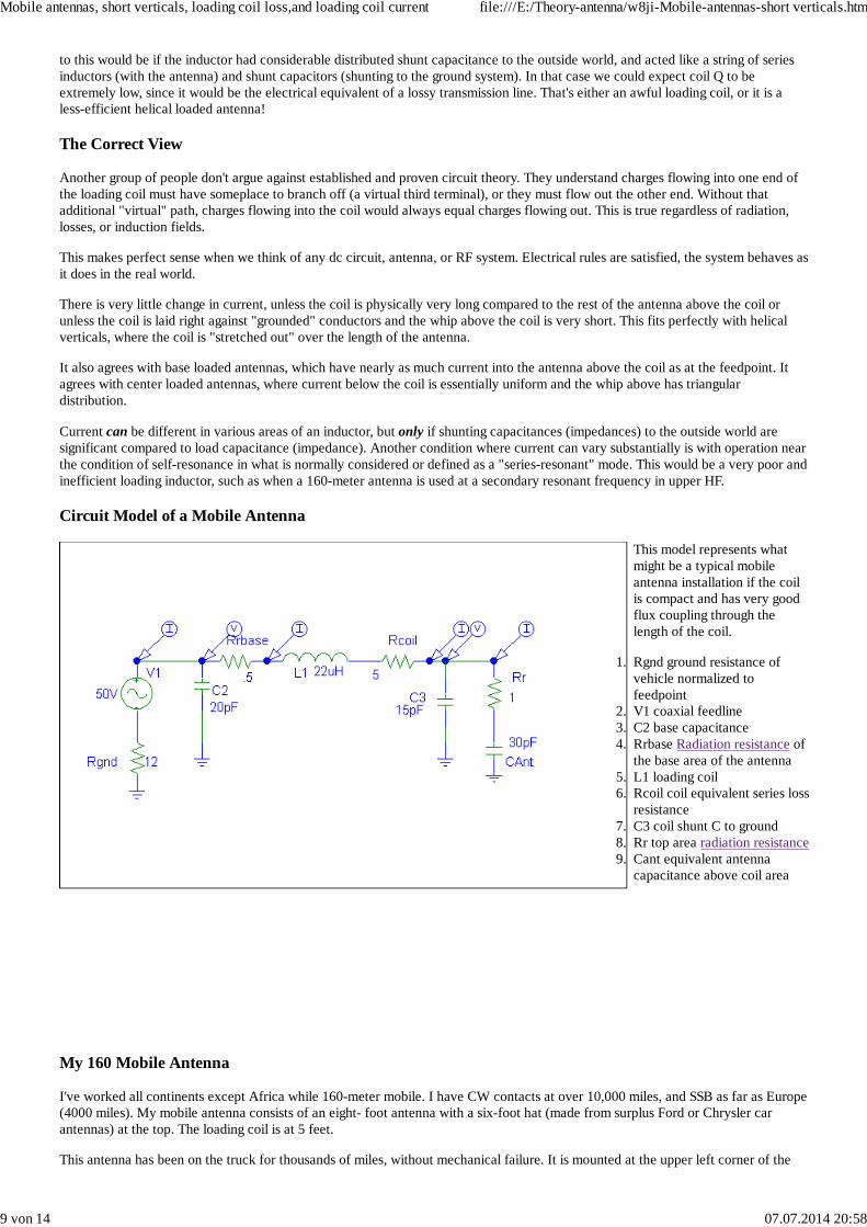
Circuit Model of a Mobile Antenna
This model represents whatmight be a typical mobileantenna installation if the coilis compact and has very goodflux coupling through thelength of the coil.
Rgnd ground resistance ofvehicle normalized tofeedpoint
1.
V1 coaxial feedline2.C2 base capacitance3.Rrbase Radiation resistance ofthe base area of the antenna
4.
L1 loading coil5.Rcoil coil equivalent series lossresistance
6.
C3 coil shunt C to ground7.Rr top area radiation resistance8.Cant equivalent antennacapacitance above coil area
9.
My 160 Mobile Antenna
I've worked all continents except Africa while 160-meter mobile. I have CW contacts at over 10,000 miles, and SSB as far as Europe(4000 miles). My mobile antenna consists of an eight- foot antenna with a six-foot hat (made from surplus Ford or Chrysler carantennas) at the top. The loading coil is at 5 feet.
This antenna has been on the truck for thousands of miles, without mechanical failure. It is mounted at the upper left corner of the
Mobile antennas, short verticals, loading coil loss,and loading coil current file:///E:/Theory-antenna/w8ji-Mobile-antennas-short verticals.htm
9 von 14 07.07.2014 20:58

truck bed, about one foot back from the cab.
The following is a model of the current antenna system on my Ford F-250 HD long bed super cab truck:
The base impedance in the model is:
Frequency = 1.854 MHz.Source 1 Voltage = 24 V. at 2.35 deg.Current = 1 A. at 0.0 deg.Impedance = 23.98 + J 0.9853 ohmsPower = 23.98 wattsSWR (50 ohm system) = 2.087
Actual measurement at my Johnstonville, GA farm in open flat pastures on August 17 at 8AM. Wet soil 25.8 ohms 0j baseimpedance, pretty close agreement to EZNEC model and earlier data! (I did have to adjust the model for very low ground conductivity,otherwise the resistance was far too low. It's my belief that NEC-2 underestimates ground losses in small radial or counterpoise systems that are close to earth.)Earlier text shows a base resistance of 28 ohms, that was dry soil with a slightly different loading coil and antenna.
The modeled current distribution for 1-ampere applied at the base (in 1-foot intervals) is:
1ft= 1.0031
2 ft= 1.0091
3ft= 1.0178
4ft= 1.0318
<Coil>
5ft= 1.0175
6ft= .97512
7ft= .92984
8ft = .89522
Measuring the current into and out of the loading coil with a small thermocouple RF meter, I detect no difference This is in closeagreement with the model.
The efficiency of this antenna knowing coil Q, radiation resistance, and base resistance calculates just under 1 percent. The modelindicates about 1/3 percent efficiency. This is reasonably close.
Removing the hat (in the model only) shows the following changes:
1ft = 1.00432ft = 1.01333 ft= 1.02794 ft= 1.0566
<coil>
5 ft= .955086 ft= .72232
Mobile antennas, short verticals, loading coil loss,and loading coil current file:///E:/Theory-antenna/w8ji-Mobile-antennas-short verticals.htm
10 von 14 07.07.2014 20:58

7 ft= .27813 8 ft = open
I haven't tested the above, but with the same loading coil loss resistance the model says efficiency is now around 3dB worse.Removing the hat, with NO change in coil resistance, shows nearly loss nearly doubles. Of course the coil resistance would increase,because the loading coil nearly quadruples in size. Bandwidth is less and efficiency is less, even if I could maintain the same coilresistance.
Examples of Unequal Current
In the above models, we see that current into and out of the one-foot long coil is about the same. There is only about 2% change incurrent even though the coil occupies 12% of antenna length in the "hat-loaded" antenna, but in fairness I couldn't resolve thatchange with a reasonably good RF current meter.
The model predicts 10% change in a non-hat antenna, but I never measured that antenna to confirm it.
Clearly there is no basis to the claim current is high only in the first few turns of an inductor, or that current tapers in relationship to"electrical degrees". The most accurate way to state the effect would be to say: "When the loading coil is short and the capacitanceof the antenna beyond the coil is reasonable (in this case 3000 ohms Xc or less), there is an immeasurable reduction in current in thecoil. When the required loading reactance is very high (in this case 8000 ohms), the reduction in current is about what we wouldexpect for an equivalent length of antenna replacing the coil."
Degrees Vs Radiation Resistance
This upper four feet of this antenna resonates near 24 MHz with the hat. We can assume it is 90 degrees long at 24 MHz, whichwould translate to 6.9 degrees on 1.85 MHz. Following that same logic, this would mean the loading coil would be about 83 degreeslong electrically. Using the incorrect logic proposed by others where the loading coil "makes up the difference in electrical degrees",there would be almost no current past the loading coil. Obviously this is not the case, the loading coil has very little "electricallength". As a matter of fact, in this case because the inductor is terminated in a fairly low capacitance and the inductor is compactwith good flux linkage through all the turns, electrical length is much closer to the physical length of the coil than the "missingantenna length" in degrees!
This goes back to radiation theory, and my favorite saying: "Five hundred feet of wire in a one foot long tube is still one foot ofantenna". Some CB manufactures sell antennas to consumers with the claim they use 5/8 or 3/4 wavelength of wire in an eight-footfiberglass whip, so the antenna has more gain. Obviously this is not true. Let's not let such silly claims spread into amateur radio!
Related topics:
Inductors
The spice inductor model shows one example of how unequal current is created. The model demonstrates a coil having significantdistributed capacitance to the point of current return in the system compared to terminating impedance of the coil. In a monopole thisreturn path would be to the groundplane, or anything closer to the potential of the groundplane than the area above the loading coil'sposition in the antenna system.
Another Practical Antenna Example
Let's assume we have a lossless 15.3 foot long 0.2 inch diameter conductor over a perfect groundplane. Eznec gives the 1.821 MHzbase impedance as .3004 -2169j. In other words, the antenna "looks like" .3004 ohms of load resistance in series with 40.32pF on1821kHz. The return path for current is through the .3004 ohm resistance and 40.32pF capacitance, back to the ground of theantenna (it is a Marconi antenna).
Such a termination (load) would require a series inductance of 2169j (189.57µH) to cancel feedpoint capacitive reactance. A typical190µH inductor would be rather large, requiring somewhere around 53 turns when using a 4" by 4" form factor. One would expect aphysically large inductor to have noticeable but very small displacement currents to the groundplane, when the small stray coilcapacitance is compared to the 40.32pF termination capacitance. This raises two very important design guidelines:
When installing a loading coil of substantial inductance in an electrically short antenna, sheetmetal and dielectrics shouldbe kept away from the coil and areas of antenna above the loading coil. This would include dielectrics on or near theinductor, since the presence of dielectrics would increase undesirable capacitance.When inductive reactance requirements are large, as when short thin "stingers" without hats are used above a coil, the coilform factor should lean more towards long and thin. Capacitances near the open end of the coil (high voltage end) shouldbe minimized. This would be true even when the coil length increase results in a small reduction in mutual turns coupling,since the stray capacitance may result in a larger loss penalty than the slight increase in accumulated resistance fromadditional wire length.
Efficiency
Mobile antennas, short verticals, loading coil loss,and loading coil current file:///E:/Theory-antenna/w8ji-Mobile-antennas-short verticals.htm
11 von 14 07.07.2014 20:58

Efficiency in any antenna near earth is almost always dominated by ground related losses, short-height Marconi antennas are noexception. The overall effect of loading inductor Q and matching system losses are "diluted" or "swamped-out" by ground losses.Ground losses cause most systems to have greatly reduced sensitivity to inductor design.
The only consistently predictable factor in efficiency in fractional wavelength Marconi antennas with limited size ground systems isradiation resistance. Efficiency increases almost directly in proportion to radiation resistance.
Radiation Resistance and Power Radiated
Radiation resistance is probably the most poorly defined term used with antennas. The lack of clear definition creates errors andmisjudgments when predicting antenna performance. If you wish more detailed information, this page contains information onradiation resistance. For the purposes of this discussion and to avoid pitfalls associated with using feedpoint impedance as radiationresistance, I'll use the same definitions Jasik, Balmain, and others have used. This definition is based on the IRE definition ofradiation resistance being equal to the net or effective current causing radiation squared divided by the power radiated as EM energy,or Rr=Pr/I^2.
Using this definition, a folded dipole has a radiation resistance identical to a conventional dipole of the same physical dimensions (~70 ohms).
Radiation is caused by charge acceleration, there is no magic. The only thing affecting radiation resistance in a short vertical antennanear ground is current distribution over the linear area occupied by the radiation portion of the antenna. The general rules are:
Radiation resistance of a Marconi vertical in the maximum possible radiation resistance case for a given height (this is the case wherecurrent is uniform throughout the structure) is equal to 1580*(H/L)^2 where H equals height and L equals wavelength and both areexpressed in the same units. Using degrees, we see a 10-degree tall antenna has a maximum possible radiation resistance of1580*(10/360)^2 or 1580*.000772 = 1.22 ohms. This would apply even if the antenna is a vertical, DDRR, Fractal, or folded unipolewith considerable top loading.
If current is triangular, radiation resistance would decrease by a factor of four to 0.305 ohms.
Power radiated is given by I^2*Rr
With 100-watts applied to a 10-degree tall antenna, net current in a lossless antenna with uniform current distribution would be 9.05amperes. With triangular distribution, such as appears in a small diameter short base loaded whip, current would be approximately18.1 amperes. We are in serious problems if the inductor reduces current along its length, since the only possible way to radiate 100watts would be to have somewhere around 9 amperes of effective current integrated over the 10-degree vertical area of space for theradiator!
Ground Losses
All current flowing (or displaced) vertically into the antenna must equal current flowing out of the ground or counterpoise system.Even though ground losses are distributed losses, we must normalize all losses to the feedpoint in order to compare systems. Thereare cases where this will not always occur, causing us to falsely assume we have lower losses than really exist.
In this tutorial and comparison, I have normalized ground losses to the same point where radiation resistance is considered.
System Losses
(Measured data below of actual antenna given below was from 1995 data taken at a different location near Atlanta with aslightly different loading coil and antenna. There is a slight disagreement with current data. I left this all in so you can see thedeparture from measurements and models using 8 year old data.)
Base Loaded (Triangular Antenna Current Distribution) with no ground loss
Assuming we have a base-loaded antenna, and the operating frequency has a wavelength of 550 feet (around the 160-meter band), a15.3 foot vertical would fit the above 10-degree value. Interestingly enough when we compare Eznec to formulas available in older(1950 vintage) engineering textbooks, we find radiation resistance predicted by Eznec is .3003 ohms while the triangular currentestimate for the same height radiator is .305 ohms! This is an amazing degree of agreement, illustrating what we could do beforemodeling programs became available. (With perfect top loading, both Eznec and longhand calculations show approximately 1.2 ohmsof radiation resistance.)
Assuming our 15.3 foot tall (10-degree) base-loaded antenna uses a coil Q of 200, the coil has 10.845 ohms of ESR. Total resistancewith a perfect ground would be 10.85+.3= 11.15 ohms. Current into this system with 100 watts applied would be around 3 amperes,resulting in ~2.7 watts radiated and ~97.3 watts lost as heat in the inductor.
Doubling coil Q (400) would provide 5.73 ohms of base resistance with 4.18 amperes. Power radiated would be 5.2 watts, power lostas heat would be 94.8 watts. Efficiency does not quite double, changing from 2.7 to 5.2%. This results in a 2.8dB change in signallevel.
Mobile antennas, short verticals, loading coil loss,and loading coil current file:///E:/Theory-antenna/w8ji-Mobile-antennas-short verticals.htm
12 von 14 07.07.2014 20:58

Top Loaded (with no ground loss)
If we added a four-wire hat with 15-foot wires, current would no longer be triangular. While we wouldn't quite reach the optimumuniform distribution, current at the top would be about 78% of current at the antenna base. Feedpoint impedance would become 0.97-551j, and the antenna would look like 0.97 ohms in series with 159pF.
Using a coil Q of 200, we would now have 2.76 ohms of inductor loss. Current becomes 5.18 amperes. Radiated power is 26 watts,while power lost as heat becomes 74 watts. Even in the perfect ground case, the change in efficiency caused by top loading is large.Top loading (with only the hat) results in 9.8 dB change in signal level when compared to the base loaded case when coil Q remains200. Efficiency is 26%. The coil remains at ground level for easy matching and frequency change.
In this case current at each terminal of the loading coil would be essentially the same regardless of poor coil mounting techniques. Inorder to have significant current taper in the coil or in the bottom of the mast, shunt capacitance would have to be a significantcompared to 160pF. The antenna's high input capacitance relaxes inductor and antenna mounting electrical requirements.
Base Loaded (high ground loss)
My F-250HD Super Cab pickup truck, when parked over open medium quality pasture land, has a ground resistance of about 20ohms (normalized to the feedpoint) on 160 meters. Applying this ground loss to the base loaded antenna, the system has a feedpointresistance of 20+.3=20.3 ohms. (This is reasonably close to actual feedpoint resistances measured with a similar operating antenna.)Adding coil losses, the system has 20.3+10.85=31.15 ohms. (NOTE: Current coil is ~8 ohms ESR, 10.85 ohms is from ~8 year olddata) Current is sqrt (100/31.15) or 1.79 amperes.
This results in .96 watts radiated, and 99.04 watts lost as heat. Efficiency is now around .96%.
Substitution of a coil with a Q of 400 results in 25.7 ohms feed resistance, or 1.97 amperes antenna current at 100 watts. In this caseefficiency is now 1.16% for 1.16 watts radiated. The change caused by doubling coil Q with high system ground losses is about0.8dB, compared to almost 3dB in the perfect ground case! With a poor ground (in this case typical of a very large vehicle), a largechange in coil Q produces little change in system efficiency.
Another Top Loaded (high ground loss) System Example (made prior to the EZNEC model above)
Using a large hat isn't practical in a moving mobile, although it could apply to fixed stations suffering with poor ground systems.When the hat is smaller, such as a mobile requires, the loading inductor can be moved higher in the system. Such a move wouldproduce uniform current below the loading coil, with a current shape above the coil dictated by the construction of the upper portionof the antenna. My own mobile uses a six-foot diameter hat manufactured from stainless steel automobile antennas arranged in aspoke. I have no problems with wind or occasional obstructions. While unsightly, a modest hat is workable.
In order to keep the systems comparable I'll use the same radiation resistance provided by a large hat, but intentionally add highground loss as a lumped resistance. This model ignores field losses near the antenna.
In this case we have 0.97 -551j as the inductor termination presented by the antenna. With ground losses normalized at 20 ohms andan inductor Q of 200, we have 20+2.76+.97 = 23.73 ohms of feedpoint resistance. Current is 2.05 amperes, and power radiated is 4.1watts. Power lost is 95.9 watts.
Efficiency is 4.1%, a 6.3dB increase over a base-loaded triangular current system with the same lossy ground. This system is 8dBdown from the same "top-loaded" distribution using a perfect ground.
When the system has significant fixed losses, increasing radiation resistance four times by top loading provides a similar dividend insystem efficiency. At the same time a substantial increase in coil Q provides only minimal change in field strength.
Current Through Coil
Related pages:
Inductor spice model
There has been some speculation that current is high only in the first few turns of a loading inductor. Radiation comes solely fromcharge acceleration or current over spatial (in line) distance.
If any loading inductor shows substantial decrease in current over the length of the inductor, it is an absolute certainty that theinductor is poorly designed and that the system above the loading inductor is not contributing to system efficiency. The reason forthis is very simple and straight forward. Any two-terminal component (even considering wire as a "component" applies) MUST haveequal charges flowing into and out of each terminal. Voltages to other reference points can be different, but for every charge movinginto one terminal a like number of charges MUST move out of the other terminal. Radiation, induction fields, and loss resistanceshave no influence on this rule.
In order to have any change in current, there must be an additional path or paths for charges. This path can be through leakage
Mobile antennas, short verticals, loading coil loss,and loading coil current file:///E:/Theory-antenna/w8ji-Mobile-antennas-short verticals.htm
13 von 14 07.07.2014 20:58

resistances, or through fictitious currents called displacement currents. Whatever the path, the total charge movements must bereconcilable. We simply can not have current "disappear".
The normal path upsetting "unbalancing" current into and out of each terminal in an inductor is provided by displacement currentsthrough electric fields. As with any system, the amount of current flow is proportional to potential difference and impedance of thepath. In order to shunt a substantial current out of an inductor, the potential difference between the ends of the path has to be highcompared to the impedance of the path. The impedance of the stray path must also be reasonably low compared to the normaldesired path.
Current diversion is problematic in very large inductors operated at (or very near) internal self resonance, when the self resonance iswhat we typically refer to as a "series-resonant" condition. This condition is common in plate chokes used in vacuum tube poweramplifiers, where the system operates over many octaves of frequency range.
"Series resonances" inside components occur when distributed inductance forms a pair (or multiples of pairs) of "L" networks. Thelarge series inductance from each end of a winding reacts with the small stray capacitance at the center, and forms a very highimpedance transformation L network. The electrical potential at the center of the system becomes extremely high, and even thesmallest amount of capacitance to surrounding objects will carry a substantial displacement current. The large displacement currentscause the terminal impedances to drop, and allow considerable current to concentrate in small areas of the component. At the sametime, considerable voltage can be present. The normal result is arcing or destruction of the component, or failure of the systemdepending on the choke to operate.
Series resonance always occurs at a frequency higher than the self parallel resonant frequency of the component. A loading coiloperating under such conditions would be required to have serious design errors to fall into this category, since the end terminationcapacitances should always be substantially higher than stray capacitance throughout the component. Failure to follow this rulewould result in needless loss and reduced SWR bandwidth in an antenna.
The speculation or supposition that the first few turns of a loading coil carry most of the current is clearly untrue. In order to shuntcurrent off, high series impedances would have to exist along with high stray shunting capacitance to areas removed from theradiator. Additionally, the remaining coil area connected to the top area of the antenna above the loading coil would have to present ahigh impedance to the area where current reduction occurs. This would never be the case, unless the top area of the antenna andloading coil are not resonant near the operating frequency.
A reasonable test for proper inductor and system design would be to remove the antenna above the loading coil, measuring systemresonance. If resonance does not change substantially, the area above the coil is not correctly terminating the system. First-order selfresonance of the inductor (parallel resonance), when removed from the system, should also be far above the operating frequency ofthe system. If self-resonance comes within three or four times the operating frequency range, the loading coil almost certainly willhave needless performance shortfalls.
Conclusion
A normally functioning inductor has essentially equal currents throughout the inductor, loading coils are no exception. Any currentdifference requires "missing current" flow through undesired stray capacitances (displacement current) or leakage currents.
In a reasonably well-designed system, current into and out of the loading inductor should be substantially equal. Large differences incurrent would indicate excessive and problematic undesired stray capacitance in the loading coil or antenna system design.
Reduced sensitivity to coil Q is primarily a function of additional losses in the system, not reduction of current through the coil.
Also see Loading Inductors
This page has had visits since February 11, 2004.
Mobile antennas, short verticals, loading coil loss,and loading coil current file:///E:/Theory-antenna/w8ji-Mobile-antennas-short verticals.htm
14 von 14 07.07.2014 20:58