Embed Size (px)
Citation preview
Nikon
HOTT TO USE A MICROSCOPE ANDTAKE A PHOTOMICROGRAPH
,:.,ti". :
F*it*

How to use a microscope and take a photomicrograph
Intnoduction
This manual is desigrred to provide basic and useful information for a
variety of microscope users: for beginners who are just learning how to
handle microscopes, for those who now use microscopes in their work,
and those who take photomicrographs for recording data and makingpresentations to academic societies and professional groups. It is alsointended for those who wonder why there are so many diaphragms and
controls on a microscope, and for those who want to take betterphotomicrographs. This manual gives a minimum basic knowledge
about the role and function of each part, and the correct operationalprocedures, mainly microscope handling and photomicrography.
Explanations will help you to get the best performance from your
microscope and so that you can take consistently high-qualityphotomicrographs.
This manual is composed of Chapters I to VII. Not only beginners
but also those who wish to take photomicrographs only will benefit from
reading this manual from the beginning.
Before using a microscope and taking photomicrographs, be surethat each part is clean, especially the seven parts of the optical system,
as described in Chapter V (1) "Points to Be Cleaned". If the microscope
is used every day, this is especially true. In addition, this manual
explains the system in which a NIKON OPTIPHOT microscope is used
in combination with the UFX-IIA photographic attachment.In this manual, "F diaphragm" means "field diaphragm" and "A
diaphragm" means "aperture diaphragm."

I .
II.
C,ontents
IIr.
Optical and Mechanical System Configrrrationancl Nomenclatule1. Optical path diagram2. Magnification principles3. External view and nomenclature
Obseruation a:ad Photomictography Procedures1. Observation procedures2. Photomicrography procedures
Optical Miooscopes and Their Operation1. Field diaphragm2. Aperture diaphragm3. Condensers4. Koehler il lumination5. Focusing6 . H a l o g e n l a m p . . . . . . . . . . . .7. Resolution8. Total magrification9. Objectives
I
68
9101113L41610
lo
L7
nnBn30
s2
3638
fV. Photornicrngraphy and Its Operation1. Precaut ions dur ing photomicrography . . . . . . . . . . . n2 . C o l o r t e m p e r a t u r e . . . . . . . . . . . . . . . . . . . . . . ' . . . . . ' . . . . . . . . 2 03 . C o l o r t e m p e r a t u r e c o m p e n s a t i o n f i l t e r s . . . . . . . . . . . . . . . . . . . . . ' . . . . . . . . . 2 [4 . C o l o r f i ] m . . . . . . . . . . . . . . . . . . . . . . . n '5 . B l a c k - a n d - w h i t e f i l m . . . . . . . . . . A6. Precaut ions to prevent uneven development . . . . . . . . . . . . . . . . . . . . . . . . . 24?. Reciproc i ty Law Fai lure . . . . . . .%8. Average and spot exposure measurement . . . , . . . . . . %9. Precautions during photomicrography by different observation methods
a) Differential Interference Contrast (Nomarski) Observationb) Fluorescence Observationc) Phase-contrast Observationd) Metallurgical Brightfield Observatione) Metallurgical Darkfield Observationf) Metallurgical Nomarski Observationg) Stereoscopic Microscope
V. Microscope Cleaning and Storage1. Dust c leaning points . . . . . . . . . . .2 . W i p i n g3. Cleaning tools4. Microscope storage ...
VI. Referrnce Data1 . Lamp voltage and color temperature curve .... .. . ..2 . 35mm camera opt ica l data . . . . . . . . . . . . .3. Microscope illumination
2

How to use a microscope and take a photomicrograph
I. OpticalandMechanical System Configuration andNomenclature
1. Opticalpathdiaepm
Introduced here is an optical path inthe optical microscope with aphotomicrographic attachment.
<Configuration>
Lamp housing (OPTIPHOT)
Stand (OPTIPHOT)
Condenser (Swing-out type)Objectives (4X, 10X, 20X, 40X, 100X)Eyepiece tube (F tube)Eyepiece (CFW 10X)
Projection lens (PL 2.5X)Photomicrographic attachment(UFX-IIA)
Camera adaplet
Photomuhipl ier
CF PL lens
nJDe pflsms rv
Heat absolbing filter \ DiffuserField diaphragm
Filters
Optical system in a photomicrrcgraphic system(Composed of the Nikon OPTIPHOT microscope and the UFX-IIA
photomicrographic attachment)
3

2. lVlagnifrcation principles
The principle ofa microscope is that two convex lens systens are appropriately
combined to magnifu specimens.
Close to a specimen, a convex lens system Lo called an objective is used
for 1-100 times magnfication to create a real image A'B'. Close to the eye, a
lens system called an eyepiece is used for 5-20 times magnification to create a
virtual image A"B" at the distance of distinct vision ( about 250rnrn from the
eye).
It is this magnified image A"B" that human eyes obsewe during
microscopy.
--i'"l=--'T I
'//Zi==-I ntermediatermage
Spscimen

3. &termal view and nomenclature
Staoe Y-axis travel knob
Stage X-axis travel knob
Coarse focus knob
Fine focus knob
Filter holder or cassette
How to use a microscope and take a photomicrograph
tl,Brightness indicator
Fuse holder
Interpupil lary distance scale Microflex clamp screw
Trinocular eyepiece tube
Also as power

IL Obseryation and Photomicrography hrcedures
1. Obsenrationpmooeaures
Color temperatu-rre setting(1) Set the power switch to ON.(2) Adjust the power voltage at
PHOTO (9V).(3) Place the NCB-10 and ND-16 filters
in the optical path, then removethe lemon skin filter (Diffuser).
Condenser centering(4) Position a specimen and focus on
it with the 10X objective.(5) Adjust the F diaphragm so that its
image enters the viewfield, thenfocus the diaphragm image bymoving the condenser up anddown.
(6) Provide a centering procedure sothat the field diaphragm imageand the field of view becomesconcentric circles.
(7) Open the F diaphragm so that thecircumference of the illuminatedarea circumscribes the eyepiecefield of view.
Lamp centering(8) Stop down the A diaphragm to a
minimum and release the Fdiaphragm.
(9) Place a centering tool to which theND2 filter is attached, on the fieldlens, then observe the aperturediaphragm surface from underthe condenser. Focus on thefilament image formed on theaperture diaphragm surface, bymoving the lamp housing backand forth.
(10) Bring the filament image to thecenter on the condenser'saperture diaphragm surface.
(11) Place a lemon skin filter(Diffuser) in the optical path.
F diaphragm image
A diaphragm
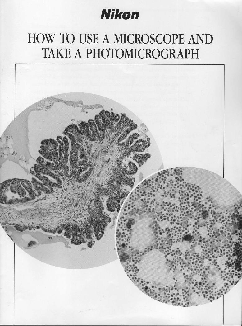
Interpupinary distance and dioptenconection adfiushent(12) Observe the specimen and adjust
the interpupillary distance so thatthe left and right viewfieldsDecome one.
(13) Make a diopter adjustment.a) Swing the 40X objective intoposition and focus on a specimenwith the coarse-fine focus knob.b) Swing in the 4X objective, andfocus the specimen by turning thediopter ring while lookingthrough the right eyepiece withyour right eye only.c) Focus the specimen by turningthe diopter ring while lookingthrough the left eyepiece with yourlelt eye only.d) Repeat twice.
Obsewation adjustnent(14) Place a specimen on the stage for
your obsewation and swing theobjective to be used in the opticalpath, bring the specimen imageinto focus.
(15) Focus the F diaphragm imagewithin the viewfield by moving thecondenser up and down, thencenter the F diaphragm.
(16) Stop the A diaphragm down to 70-807o of the objective NumericalAperture.Note: When the objective orspecimen is changed, perform(15), (16) again.
How to use a microscope and take a photomicrograph
Field diaphragm image
Eyepiece vie$lield diaphragm
diaphragrn
A diaphragm imags

2. Photomicrography hrcedures
(1 ) Open the back of the dark box andload the film.(The sprocket teeth should engagethe perforation ofboth edges of thefilm.)
(2) Press the WIND button 2-3 timesuntil the frame counter indicates
(3) Set the ISO/ASA film speed byusing the switch.
(4) Select either spot or averageexposure measurement.(See IV (8))
(5) Stop down the field diaphragmand aperture diaphragm.
(6) Make adjustment with ND filtersso that the shutter speed becomes0.25-0.07 seconds.
(7) Focus on a specimen. (See III (5))
(8) Press the exposure switch.Note: When an objective ischanged, start with (4), or startwith (6) if the specimen ischanged.
@...\ ../,,,)@(,,,,/ \Finder
WINDo
ISO/ASA
ntlill
i
- frr#-
T !4E
nU
nU
nU.
1,
nu
mwField diaphragm Aperture diaphragm

How to use a microscope and take a photomicrograph
Itr Optical Micnoscopes and Their Oper:ation
1. Field diaphragm
The field diaphragm is used to restrict the illumination range (observationrange). The residual diffused reflected light occuring on the specimen or lenssurface is restricted by stopping the field diaphragm ?own to the requiredrange. As _a result, flare is reduced and a high contrast specimen image canbe observed. This is especially important in photomicrogriphy.
Field dlaphragm image
35mm Jilm viewlleld
Operatingtips
(1) When observation through the eyepiece tube is performed, adjust the Fdiaphragm so that the circurrrference of illuminated area circumscribes that ofthe eyepiece field of view as shown in the figure above.
(2) However, when only a certain part of the viewfield has to be observed withhigh contrast and high resolving power, it is recommended that it be stoppeddown by just leaving the part to be observed. This is especially effective diiringfluorescence or differential interference contrast observations.
(3) To prevent fading in an unnecessary part ofa specimen during epi-fluorescence observation or photomicrography, stop down the F dlaphragm,excite only- the necessary part. Then, the specimen's fading area will bemlnlmrzed.
(4) During photomicrography, it is recommended that the diaphragm bestopped down as shown in the above right figure so that the diameter oftheilluminated area be set slightly larger than the diagonal of the film format.
(5) It is important to focus the field diaphragm image by moving the condenserup and down.
(6) Especially when oil-immersion objectives (more than 40X) are used with anAA condenser, it is recommended to apply oil between the condenser and theglass slide. As a result, the edge of the F diaphragm image and the imageitself becomes dark, exhibiting the effect ofthe freld diaphragm to the fullest.
2. Aperture diaphragm
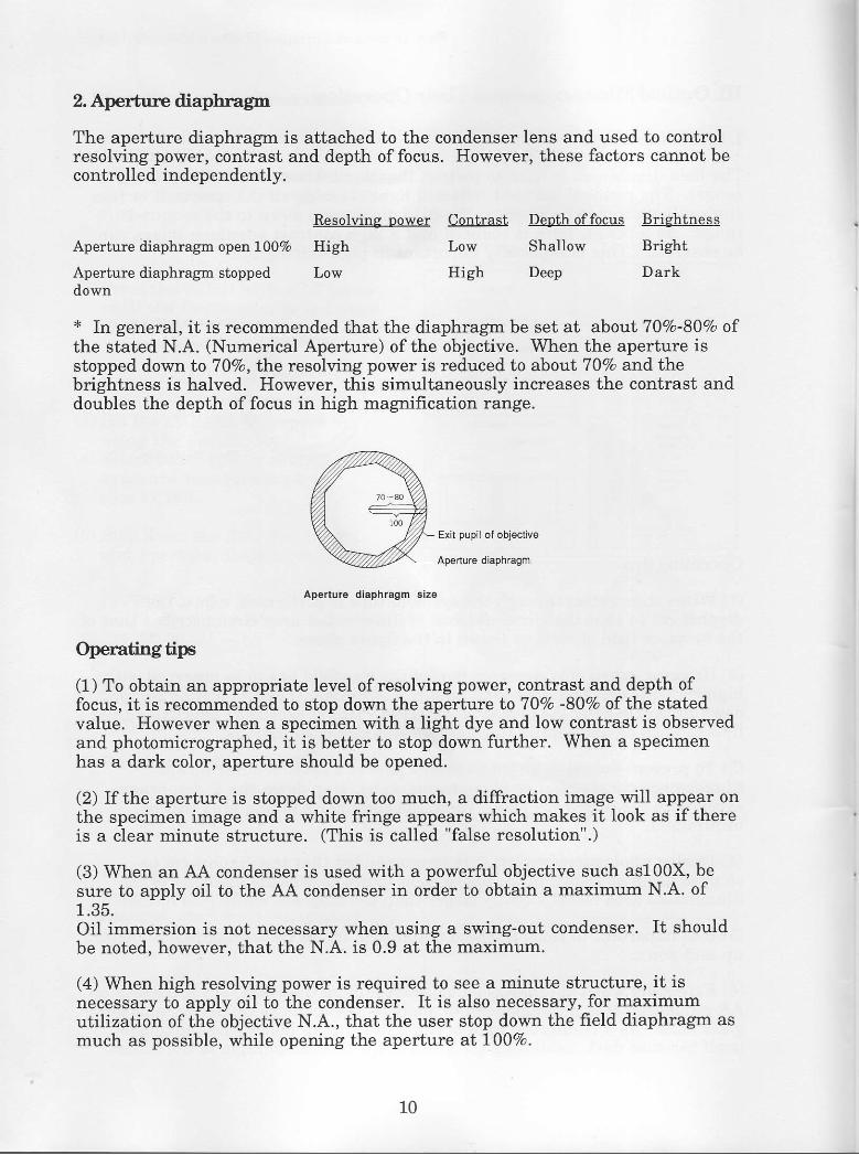
The aperture diaphragm is attached to the condenser lens and used to controlresolving power, contrast and depth offocus. However, these factors cannot becontrolled independently.
Contrast Denth offocus BrightnessResolvine nower
Aperture diaphragrn open 1007o High
Aperture diaphragrn stopped Lowdown
Low Shallow
High Deep
Bright
Dark
* In general, it is recommended that the diaphragm be set at about 7 0Vo-80Vo ofthe stated N.A. (Numerical Aperture) of the objective. When the aperture isstopped down to 70Vo, t}i.e resolving power is reduced to about 70Vo and t}rebrightness is halved. However, this simultaneously increases the contrast anddoubles the depth offocus in high magnification range.
Exil pupil oi objective
Aperture diaphragm
Apenure diaphragm size
Operatingtips
(1) To obtain an appropriate level of resolving power, contrast and depth offocus, it is recommended to stop down the aperture to 7lVa -80Va of the statedvalue. However when a specimen with a light dye and low contrast is observedand photomicrographed, it is better to stop down further. When a specimenhas a dark color, aperture should be opened.
(2) If the aperture is stopped down too much, a diffraction image will appear onthe specimen image and a white fringe appears which makes it look as if thereis a clear minute structure. (This is called "false resolution".)
(3) When an AA condenser is used with a powerful objective such as100X, besure to apply oil to the AA condenser in order to obtain a maximum N.A. of1 .35 .Oil immersion is not necessary when using a swing-out condenser. It shouldbe noted, however, that the N.A. is 0.9 at the maximum.
(4) When high resolving power is required to see a minute structure, it isnecessary to apply oil to the condenser. It is also necessary, for maximumutilization of the objective N.A., that the user stop down the field diaphragm asmuch as possible, while opening the aperture at l00Vo.
10

How to use a microscope and take a photomicrograph
3, Condensers
The condenser is used to obtain a bright, even viewfield. It also hasconsiderable influence on resolution, contrast, depth of focus and brightness,all of which affect the basic quality of a microscopic image. Therefore, itsutilization is very important.
Numerical anerture Illurnination Remarks( N . A . ) f i e l d
Abbe condenser 1.25 4.6a For 4X-100X(o i ] -immers ion)
Swing-out Achro- 0.90 3.4A For 2X-100Xmat condenser (12) (Dry)
AchromaVAplanat 1.35 2.80 For 10X-100Xcondenser (Oi l -
rmmers ion)
Howtoc.hoose
The Abbe condenser is suitable to use for observations in practice andinspection applications. However, the swing-out or AA condenser is the bestchoices for photomicrography (especially in color). The AA condenser isespecially suited for critical observation at high maglifications (to observeminute structures).
Operatingtips
(Abbe condensers)To be used at the point where focusing is provided to F diaphragm imagewithin the field of view.
(Swing-out condensers)2X-4X objective: To be used at the point where focusing is provided to Fdiaphragm image at 10X magrrifrcation and the top lens is swung out.10X-100X objective: To be used at the point where focusing is achieved at Fdiaphragm image within the field of view.
(AA condensers)10X-40X objective: To be used at the point where focusing is provided to Fdiaphragm image within the viewfield, without using oil.40X-100X objective: To be used at the point where focusing is provided to Fdiaphragm image within the viewfield, using oil.
oo.t
11

* When using a lX objective:
Remove the condenset and install a white frosted fiIter onto the field lens thenperform lamp centering when necessary.Pay special attention during photomicrography because uneven lighting is aptto occur.
* Condenser oil imnersing
(1) Remove any air bubbles in thenozzle of the oil container.
(2) Bring the condenser down, thenapply a su{ficient amount of oil tothe condenser top lens takingspecial care that air bubbles do notenter the oil.
(3) Slowly bring the condenser up tothe extent that the oil touches theslide glass, payrng attention sothat air bubbles do not existbetween the slide glass andconcenser.
(4) Remove the eyepiece and rnakesure no air bubbles exist by lookingat the exit pupil of the objective. Ifthere are no bubbles, thiscompletes oil immersing.
X
Objeclive exlt pupil
<Note 1> If air bubbles are obsewed, lower the condenser and wipe up the oi-,then try immersing again. In this case, always clean off the oil on the slideglass too, because air bubbles can be found here too.<Note 2> When oil immersing is being provided on condensers, it is often thecase for objectives. However, often it is impossible to judge whether the airbubbles confirmed to exist in the exit pupil of Step (4) are present on theobjective side or condenser side. To check:
Move the condenser with the condenser centering screw.
If air bubbles move: Air bubbles exist on the condenser side.
If air bubbles do not move: Air bubbles exist on the oSective side,
Alr bubbles
72
How to use a microscope and take a photomicrograph
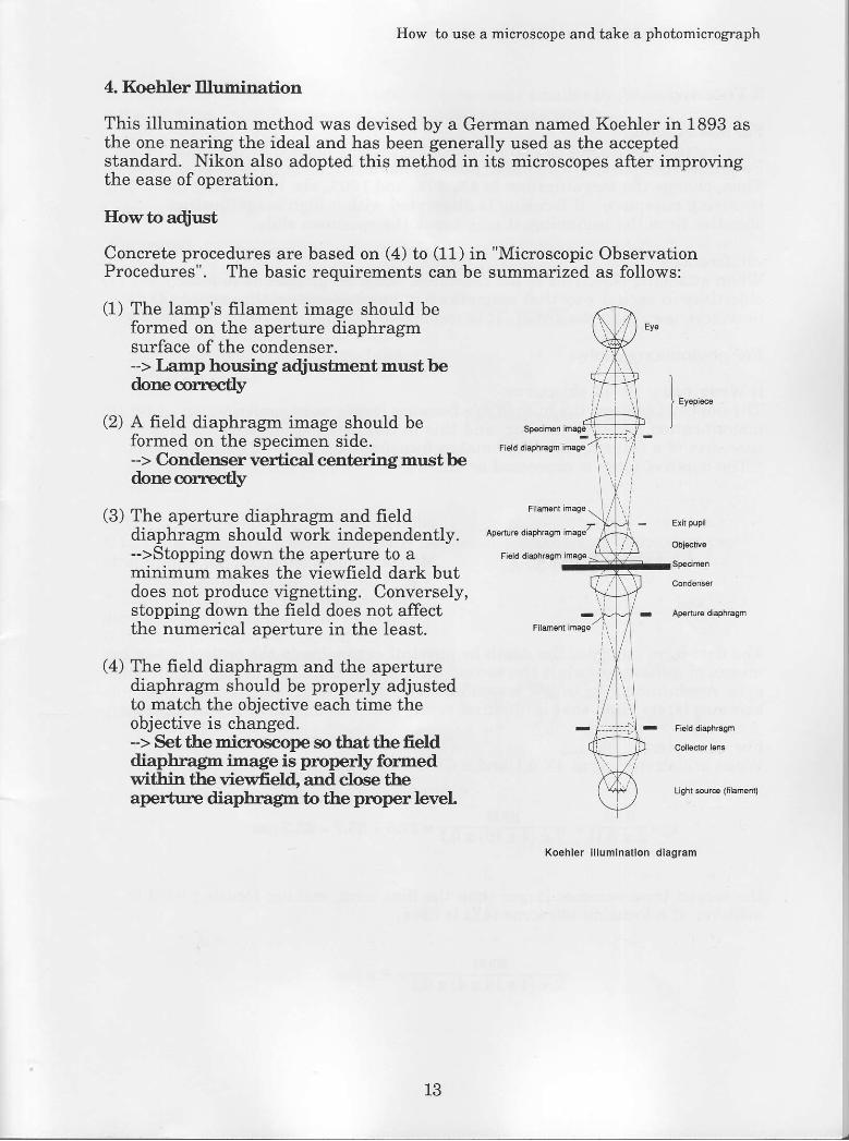
4. Koehler Illumination
This illumination method was devised by a German named Koehler in 1893 asthe one nearing the ideal and has been generally used as the acceptedstandard. Nikon also adopted this method in its microscopes after improvingthe ease of operation.
Howtoadiust
Concrete procedures are based on (4) to (11) inProcedures". The basic requirements can be
(1) The lamp's filament image should beformed on the aperture diaphragmsurface of the condenser.-> T .,.rnp housing adius' nent musf bedone oorrectly
(2) A freld diaphragm image should beformed on the specimen side.-> Condenser vertical centering must bedone corrrctly
(3) The aperture diaphragm and frelddiaphragm should work independently.->Stopping down the aperture to aminimum makes the viewfield dark butdoes not produce vignetting. Conversely,stopping down the field does not affectthe numerical aperture in the least.
(4) The field diaphragm and the aperturediaphragm should be properly adjustedto match the objective each time theobjective is changed.-> Set the microscope so tbat the fielddiapbragm image is properly formedwithin tlre viewfield. and close tlreaperturre diapbragm to tlre pnoper level
"Microscopic Observationsummarized as follows:
Aperture diaphdqm imaoezErh plpil
- Apeture diaphfagm
Koehler i l luminal ion diagram
IJ
5. Focusing
For obserwation:
Focus the specimen with a 10X objective in the first place.Then, change the magnification to 4X, 40X, and 100X, etc. by rotating therevolving nosepiece. If focusing is attempted with a high magnificationobjective from the beginning, it may break the specimen slide.
<Reference>When attaching objectives to the nosepiece, accepted practice is to attachobjectives in such a way that maglification increases when the revolvingnosepiece is rotated clockwise. It is recommended that you follow this practice.
For photomicrography:
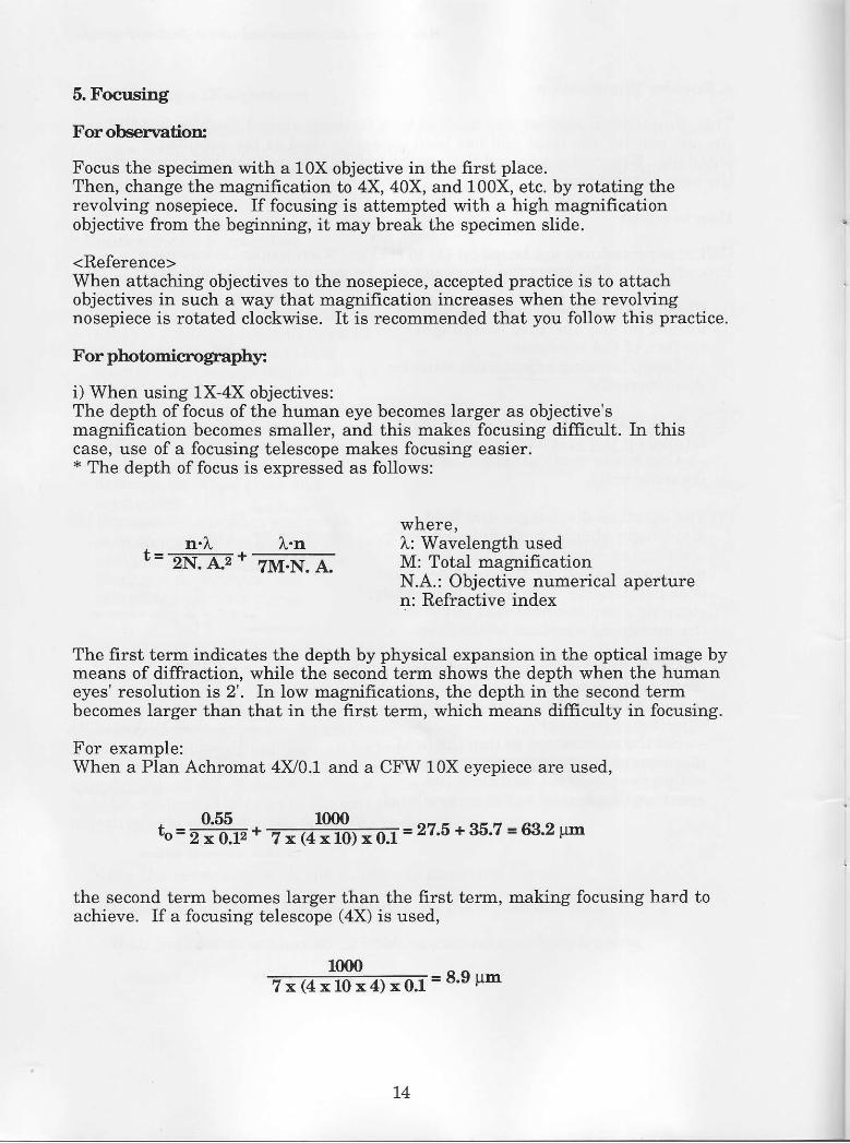
i) When using 1X-4X objectives:The depth of focus of the human eye becomes larger as objective'smagnification becomes smaller, and this makes focusing difficult. In thiscase, use of a focusing telescope makes focusing easier.* The depth of focus is expressed as follows:
. n.l. l.n t'#l?"r"r'gtt' o.uat=ZNIE +
ZII+{. A" M: Total mignificationN.A.: Objective numerical aperturen: Refractive index
The first term indicates the depth by physical expansion in the optical image bymeans of diffraction, while the second term shows the depth when the humaneyes' resolution is 2'. In low magnifications, the depth in the second termbecomes larger than that in the first term, which means difficulty in focusing.
For example:When a Plan Achromat 4Xl0.1 and a CFW 10X eyepiece are used,
t = ffi . "#t=r-1 = 27.5 +35.7 = 63.2 t'n
the second term becomes larger than the first term, making focusing hard toachieve. If a focusing telescope (4X) is used,
1 m 0 _ e o , , -7 x ( 4 x 1 0 x 4 ) x 0 . 1
- " ' " ' *
74

How to use a microscope and take a photomicrograph
the visible depth of focus of the human eye becomes smaller by 26.8pm (35.7 -8.9 = 26.8 pm), which indicates that focusing becomes easier.
<Note> Since only a portion ofthe finder's center can be seen when using afocusing telescope, determine the composition first, then position the telescopeand focus.
tFocusingl
(1) Turn the diopter ring of the finderor the focusing telescope to focusthe double cross line .
(2) Turn the fine focus knob so thatboth the double cross line and thespecimen image come into clearfocus.
(3) When using a low power objective,focus it by turning the fine focusknob 5-6 times and use theaverage value of the scalereadings.
ii) When using 10X-100X objectives:
Bad
Double cross tine [::ilof masked eyepiece I
-=--
Double cross l ineof the ocular f inder
'.\ z/,,+ )o(,,,,/ \
u ooo
A focusing telescope is not necessarily a must. Focus them as above, but payattention to the following points:
o Turn the fine focus knob in thedirection shown on the right to focus.If it was turned too far, turn it backand refocus (the direction whichmoves the stage from down to up) toeliminate the influence of play due togear slack.

6. Halogen Lamp
The halogen lamp used as a light source in the microscope has higherluminance and color temperature than conventional tungsten lamps. ItsIuminance is about four times greater.
As long as the lamp voltage is constant, the halogen lamp maintains almostthe same level of brightness and color temperature whether it is a new one orone nearing the end of the life. This light source is especially suitable for colorphotomicrography.
<Caution>(1) Do not use at an excessively low voltage. Use it within the green range ofthemeter (Iights up at 6V or more).(2) Do not touch the lamp surface directly with your bare hands during lampreplacement. When fingerprints or oil adhere to the lamp, clean it withalcohol.
7. ResolutionThe minimum distance between two dots which can be identified as thev are isknown as the resolution of a microscope.
'I
d = 0.61 x 5:; (tr.: Light source wavelengthl \ . A .
N. A.: Nurnerical aperture)
From the above expression, it is obvious that resolution does not depend onobjective magnification but depends on the numerical aperture ofthe objectiveand the wavelength ofthe light source in use.
8. Total magnification [Numerical Aperture]
N . A . = n ' s i n 0
M =MoxMe (x Mi)M: Total magnifrcationMo: Objective magnificationMe: Eyepiece magnifrcation
Me indicates Proj ection Lens(PL) magnification whenphotomicrography isperformed.
Mi: IntermediatemagnificationMi=1 with ordinarydiascopic illumination
n = 1 . 5 1 5
16

How to use a microscope and take a photomicrograph
9. Objectives
Objectivetypes
(1) CF AchromatIn this type of objective , correction of the axial chromatic aberration is appliedto the C line (red) and F Iine (blue) based on the standard wavelength. Sinceaber-rations at the center of the viewfield is fully corrected, resolution andcontrast at the center are excellent, making it ideal for general observations.
(2) CF Plan Achromat (Plan)Like CF Achromat, axial chromatic aberration is corrected for the C lirre (red)and F line (blue). However, corrections are also fully made for curvature ofthefreld and other aberrations, resulting in excellent resolution and contrast notonly at the center but at the periphery of the field. When the center is focused,the periphery ofthe ultra-wide field is simultaneously focused. Therefore, thisobjective is suitable for ultra-wide field observations and photomicrography.
(3) CF Plan Apochromat (Plan Apo)Chromatic aberration is appropriately applied across the entire visiblespectrum including C line (red), F line (blue) and G line (violet) by using afluorite and special low dispersion glass. The CF Plan Apochromat is thehighest-class objective whose numerical aperture is large and to whichcorrections ofvarious aberrations are provided not only at the center but theperiphery of the field as well. Its superb resolution color reproducibility andfreld flatness all rnake it the best objective for most microscopic examinationsand color photomicrography of minute structures.
(4) Epi-fluorescence Objectives (Fluor,{JV-F)Since ordinary objectives absorb ultraviolet light and generate fluorescence,Iens is subject to deterioration. Epi-fluorescence observations utilize ultravioletlight for observing the fluorescenCe of the specimens. Epi-fluorescenceobjectives are designed for this purpose and feature excellent transmission ofultraviolet light, no generation of fluorescence and less chance of lensdeterioration. The epi-fluorescence objective comes in dry type Fluor and UV-Ftype that utilizes glycerin.
(5) CF Polarizing Objectives (P)A polarizing microscope is used to examine the polarization characteristics ofa specimen. Since even a small distortion in the optical system influencespolarization and causes image quality deterioration, distortion is minimized indesigning polarizing objectives. The differential interference contrast (DIC)objective also features less distortion. However, in terms ofthe degree ofdistortion, DIC objectives are rated between ordinary objectives and polarizingobjectives.
(6) CF Phase-Contrast ObjectivesCF Phase-Contrast objectives are used for phase contrast obsewations ofcolorless, unstained specimens. Phase contrast processing has been applied toordinary objectives.
t7

Objective Indications
MagnificationType of objective
Working distance
Color code
Correction ring
Mechanical tube length
cover glass thicknessNumerical aperture
Cover glassSlide glass
Application
Specified immersionliquid
lmmersion mark
Parlocal distance
,/ \-- lmmersion oil
Objectives with over glass correction ring
When dry objectives with large numerical apertures (more than 0.75) are used,it is desirable that the thickness from the cover glass surface to the specimensurface is 0.17mm. However, since the thickness of a specimen, mountingmedium, cover glass, etc. is not even, it is oflen a difficult task to maintain the0.17mm. To fully display the performance of the objective, objectives with acorrection ring are designed so that the thickness between the cover glasssurface to the specimen can be corrected within a 0.11-0.23 mm range (in caseof CF Plan Achromat 60X) at the objective side.
<Adjusfurent prnocedurcs>
Open the aperture.Set the correction ring at 0.17mm, then focus the specimen. (Rememberhow the image was observed.)
(3) Rotate the correction ring by 2-3 scales toward the 0.23mm setting andrefocus. Then compare the image with that before. If the contrast is better,turn the ring in the same direction by 2-3 scales again.
(4) If the image becomes worse, turn the ring in the opposite direction by 1-2scales to obtain the best position.
(5) This procedure is necessary every time a specimen is changed.
(1)(2)
18

How to use a microscope and take a photomicrograph
No-covenglass objectives
No-cover-glass objectives are used for observing specimens without using acover glass in such cases as smeared specimens such as blood, with obj ectiveswith large numerical aperture (N.A. 0.4 or more). ("NCG" or "No CoverGlass" is engraved on this type of objectives.)Examples: CF Plan NCG 40X, CF Plan Apo NCG 100X, etc.
lReference]
The following color codes are used to show the objective magnification.
Magnification lX
Color code Black
50xLight
blue
2X
Brown
60x
Cobalt
blue
4X
Red
100x
White
10x
Yellow
20x
Green
40x
Light blue

IV. Photomicnography and Its Operation
1. Pnecautions during photomicrcgraphy.
(1) Place the microscope on a vibration-free table, preferably in a semi-darkroom.
(2) Check for dust and foreign matter in the optical system before takingpictures (Important).
(3) Set the aperture (70Vo-80Vo) and field diaphragms.--> See the Field Diaphragm,/Aperture Diaphragm section.
(4) Use a bright optical system.
When projection lenses are changed, exposures are:
PL 2.5X PL 4X PL 5X
1 sec. 2.4 see. 4.0 sec.
When using the same total magnifrcation, exposures are:
Total maenification 100X L00X 80X
Eyepiece x objective 2.5 x 40 5 x 20 4x20
Exposure t.02 I.77 1.11
(5) Use objectives with less chromatic aberration and excellent flatness. (PlanAchromat or PIan Apochromat type)
(6) Use No-Cover-Glass objectives for no-cover specimens.(7) When using lX, 2X objectives, take precautions to prevent uneven
illumination.--> See "6. Precautions To Prevent Unevenness."
( Provide centering with care - use a white frosted frlter for 1X maglification.)
2. Color temper:atureThe color temperature is used to indicate the color of the light source or itsdifference when color photomicrography is performed. When a black iron baris heated or charcoal is burnt, it becomes red as the temperature increases.Then it turns to yellow, white and blue, in accordance with further increasesin temperature. Instead of the iron bar or charcoal, the color ternperature usesa fictitious, ideal substance called a "full radiator", and its radiation energy isused as a standard. In other words, the equivalent absolute temperature of theradiating full radiator is used to indicate the color temperature of a certainlight source. The color temperature is indicated in units of Kelvin (K).
<Example>Bluesky- - - 8000-10000KSunatnoon - 5500- 6500KHalogen lamp (12V-50W) - - 3400 K (at 12V)Tungsten lamp (6V-30W) - - 2850 K (at 7.5V)
n
How to use a microscope and take a photomicrograph
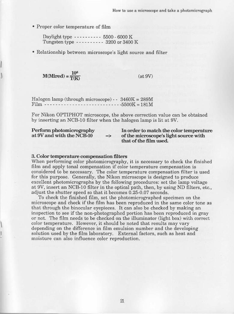
. Proper color temperature of film
Daylighttype --- 5500-6000KTungsten type - - - - 3200 or 3400 K
. Relationship between microscope's light source and filter
II lrtrvrired) =# (at 9V)
Halogen lamp (through microscope) - - 3460K = 289MF i I m - - - - - - - - 5 5 0 0 K = 1 8 1 M
For Nikon OPTIPHOT microscope, the above correction value can be obtainedby inserting an NCB-10 filter when the halogen lamp is lit at 9V.
Perforcn photomicrography hr order to match the color temperatureat 9V and with the NCB-10
tbat of the fflm used.
3. Color tempemtu-ne compensation filtersWhen performing color photomicrography, it is necessary to check the finishedfrlm and apply tonal compensation if color temperature compensation isconsidered to be necessary. The color temperature compensation filter is usedfor this purpose. Generally, the Nikon microscope is designed to produceexcellent photomicrographs by the following procedures: set the lamp voltageat 9V, insert an NCB-10 frlter in the optical path, then, by using ND filters, etc.,adjust the shutter speed so that it becomes 0.25-0.07 seconds.
To check the finished film, set the photomicrographed specimen on themicroscope and check if the film has been reproduced in the same color tone asthat through the binocular eyepieces. It can also be checked by making aninspection to see if the non-photographed portion has been reproduced in grayor not. The fiIm needs to be checked on the illuminator (Iight box) with correctcolor temperature. However, it should be noted that results may varydepending on the difference in film emulsion number and the developingsolution used by the film laboratory. External factors, such as heat andmoisture can also influence color reoroduction.
.L

Filters that are designed to eliminate the background color (white portionwhere no specimen is photographed) are shown below.
Background colors and appropriate color temperatu.r,"e compensation filters
Background colors to be absorbed
Blue
Green
Red
Blue and green (cyan)
Blue and red (magenta)
Red and green (yellow)
Color temoerature comnensation filters
CCY series (yellow)
CCM series (magenta)
CCC series (cyan)
CCR series (red)
CCG series (green)
CCB series (blue)
Basically, the microscope's color temperature can be matched to the film'sproper color temperature if photomicrography is perforrned with a 9V lampvoltage and by using an NCB-10 frlter. Since the ratio of short wavelength(blue) and long wavelength (red) can be made constant, color temperaturecompensation is generally necessary for middle range wavelength only. Inother words, it is only necessary that the user prepares a total of eight colortemperature compensation filters----one each of 5, 10, 15, 20 for both CCM(Magenta) and CCG (Green) (available at any camera retailer). For variousother situations, refer to the above table.
Utilization of color temperatune compensation filters when the backgrcund iscolored.Place the reversal fiIm on the illuminator with the correct color temperatureand overlay the proper CC filter on top ofit, to make the background gray.Place this CC filter on the field lens and take a photomicrogtaph again. Thismakes the background color gray.
4. Color ffImSince medical photomicrography requires excellent color reproduction, highresolution, and superb color contrast, etc., daylight reversal color film isgenerally used for this purpose.
For general tissue specimens, priority of importance is given to resolution andcolor reproduction, so it is not recommended to use film with excessively highsensitivity: Reversal film with ISO/ASA lfi) or less is necommended.
n
How to use a microscope and take a photomicrograph
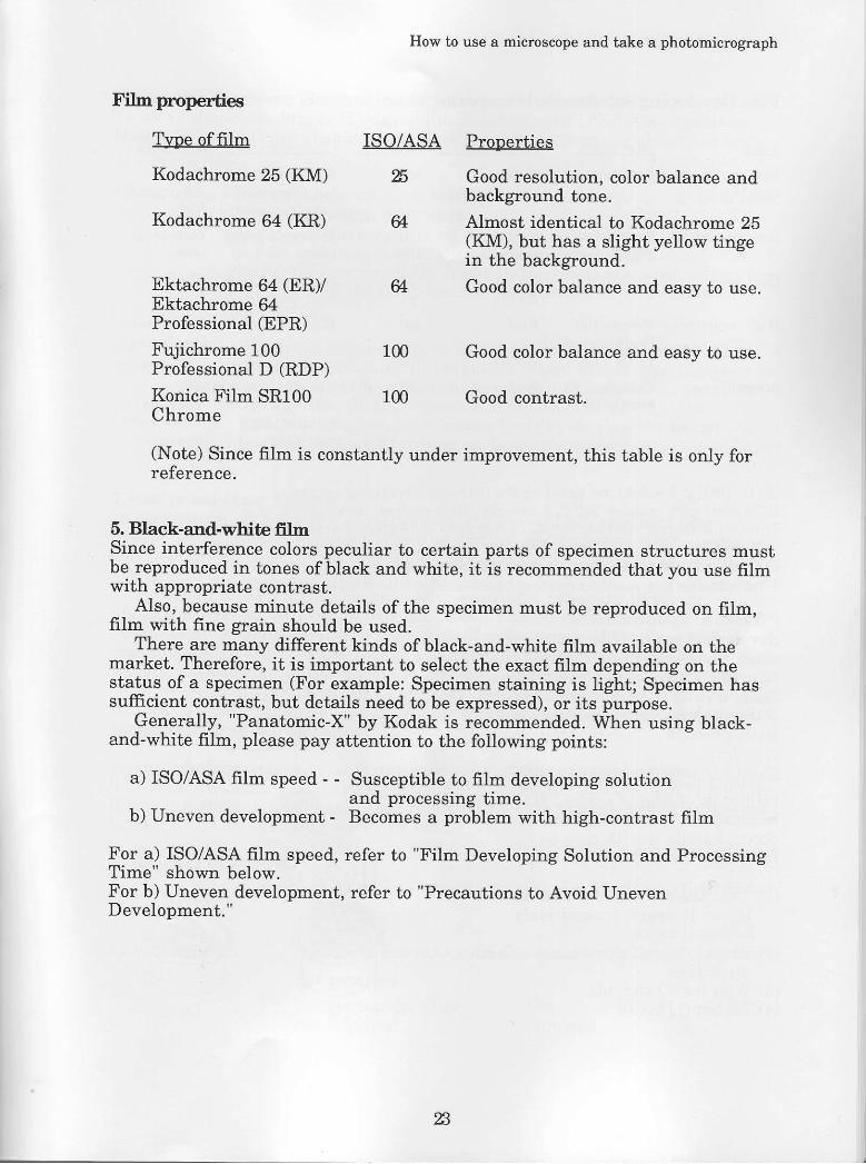
Filnpoperties
Type offilm ISO/ASA
Kodachrome 25 (KM) %
Kodachrome 64 (KR) &
Prooerties
Good resolution, color balance andbackground tone.Almost identical to Kodachrome 25(KM), but has a slight yellow tingein the background.
Good color balance and easy to use.
Good color balance and easy to use.
Good contrast.
Ektachrome 64 (ER)/Ektachrome 64Professional (EPR)
Fujichrome 100Professional D (RDP)
Konica Film SR100Chrome
&
100
100
(Note) Since film is constantly under improvement, this table is only forreference.
5. Black_and_white fftrnSince interference colors peculiar to certain parts of specimen structures mustbe reproduced in tones of black and white, it is recommended that you use fiImwith appropriate contrasr.- , Also, because minute details of the specimen must be reproduced on film,film with fine grain should be used.
There are many different kinds of black-and-white fiIm available on themarket. Therefore, it is important to select the exact film depending on thestatus of a specimen (For example: Specimen staining is light; Specimen hassufficient contrast, but details need to be expressed), or its purpoJe.
Generally, "Panatomic-X" by Kodak is recommended. When using black-and-white film, please pay attention to the following points:
a) ISO/ASA film speed - - Susceptible to film developing solutionand processing time.
b) Uneven development - Becomes a problem with high-contrast film
For a) ISO/ASA film speed, refer to "Film Developing Solution and ProcessingTime" shown below.For b) Uneven development, refer to "Precautions to Avoid UnevenD evelopment. "
%

Film Developing Solution and hocessing Time
Tvoe
Low sensitivity,high resolution
General use
Copy use
Filrn name
Panatomic-X
Neopan SSPlus-X Pan
Manufacturer
Kodak
Fuj iKodak
FujiKodak
Fuji
Kodak
Kodak
ISO/ASA
100
Characteristics
Low sensitivity,but fine grained
Moderate grada-tions
High resolution,high contrast
High resolution
Variable contrastwith developingsolution; highresolution
Remarks
Tissuespecimens,ICs
Universaltype
ICs
Fluorescentspecimens
DICspecrmens;fluorescentspecimen
High sensitivity Neopan 400ProfessionalTri-X Pan
Scientific use Technical PanFilm 2415
1m100
n&
400
lm
50
(Note) ISO/ASA values are based on the following developing solutions:D-76 developing solution:20'C, 8 minutes. High contrast development.Finedol developing solution: 20'C, 10 minutes. Fine-grain development.
6. Erecautions to prevent uneven developmentIJnevenness pnevention duringblack-and-white fflrn development
* There are two different reeldeveloping tanks. The stainlesssteel, direct-reel tank has less chanceof uneven development. With thistank, rolling in of frlm is somewhatdiffrcult. however. it becomes easierwith practice.
* With a plastic, belt-reel tank,rolling in of film is easier. However,because unevemess is liable tooccur, handle it with care byfollowing these directions :
(1) Take the roll out ofthe tank,insert it again, immediately.Repeat it twice.
(2) Rotate the roll three times in bothdirections.Wait for 30 seconds.Repeat (1) to (3).
(Stainless steel tank)Shake it for 10 seconds,rest for 30 seconds.
c+tl-1 |(___, '
(3)(4)
qA

How to use a microscope and take a photomicrograph
Pnevention of uneven illumination with low power otrjectivesThere is almost no danger of uneven illumination with 10X-100X objectives.However, special care should be taken when using low-power objec[ives suchas 1X. 2X. 4X.
1X objectives: Remove the condenser lens and place a diffuser on the fieid lens.Field diaphragm fully open.Make sure that there is no difference in brightness between thecenter and periphery of the viewfield, by looking through thebinocular eyepiece tube. If any difference is observed, adjust forit by moving the lamp housing back and forth or by lampcentering.
2X, 4X Swing out the top lens by using a swing-out condenser. Afterobjectives: confrrming Koehler illumination (Field diaphragm image must
be formed on the specimen) by using a 10X objective, swing outthe top lens. If any unevenness is observed through thebinocular eyepiece tube, adjust for it by moving the lamphousing back and forth or by lamp centering.
7. Reciprocity Law FailureIn accordance with the Iaw of reciprocity, the amount of exposure is theproduct of luminance applied to the frlm surface and exposure time. Based onthis law, the same exposure is obtained either with f5.6 and 1/60 sec., or E and1/30 sec.
However, a discrepancy occurs under prolonged exposute time. Inphotomicrography, especially, exposure time is apt to become lengthy. This isattributable to the special charactenstics of microscopy-it requires highmagnification, makes use of special properties of light, and uses only aspecified wavelength. This results in low level light and long exposure time.
Because of the failure ofthe reciprocity law, the prolonged exposure timeresults in under exposure and loses color balance. In this case, mere exposurecompensation is not enough.
During photomicrography, it is important that shutter speed be within 0.25-0.07 seconds. This is adjusted by using ND filters if the level of light is high, orif it is insufficient, by changing the combination of the objective and projectionIenses, or by using highly sensitive fllm.
<Fikn data examples>
Kodachrome 25(KM)
1n000-1/10
Exposurecompensation *|st"p
not required
Compensation filternot required
Unit: in second
10 100
+2 steps +3 steps
Not CC10B CC20Brequired
%
].t4000-r I 161 r .
Exposure compensation +;step +! step
g2
+1 stepFujichrome 100 Pro-
fessional D (RDP) not required
Compensation filter CC5R CC5R CC10Rn n + r a n r r i r o d
8. Average and spot exposure measurrementThe proper exposure time can be usually obtained with a photomicrographicattachment featuring automatic exposure. However, it is not always truedepending on the specimen color and the distribution oftissue. This is due tothe use of average exposure measurement, or the fact that the light detectorhas a characteristic which is more sensitive to red. (Sensitivity to red is slightlyIow in a photomicrographic attachment that uses a photomultiplier as anoptical detector. )
Especially when a specimen with only blue or only red is used, special careshould be taken for exposure compensation. Considering the congenialitybetween the specimen and the photomicrographic attachment, test shooting isrecommended for safety. In this case, try several shots by changing exposuresby +3 steps per 2/3 step, based on the automatically set shutter speed. (Duringgeneral brightfi eld observation)
Test photomicrosraphy --> -2, tt, 3, o, .3, t*, +2 (step)
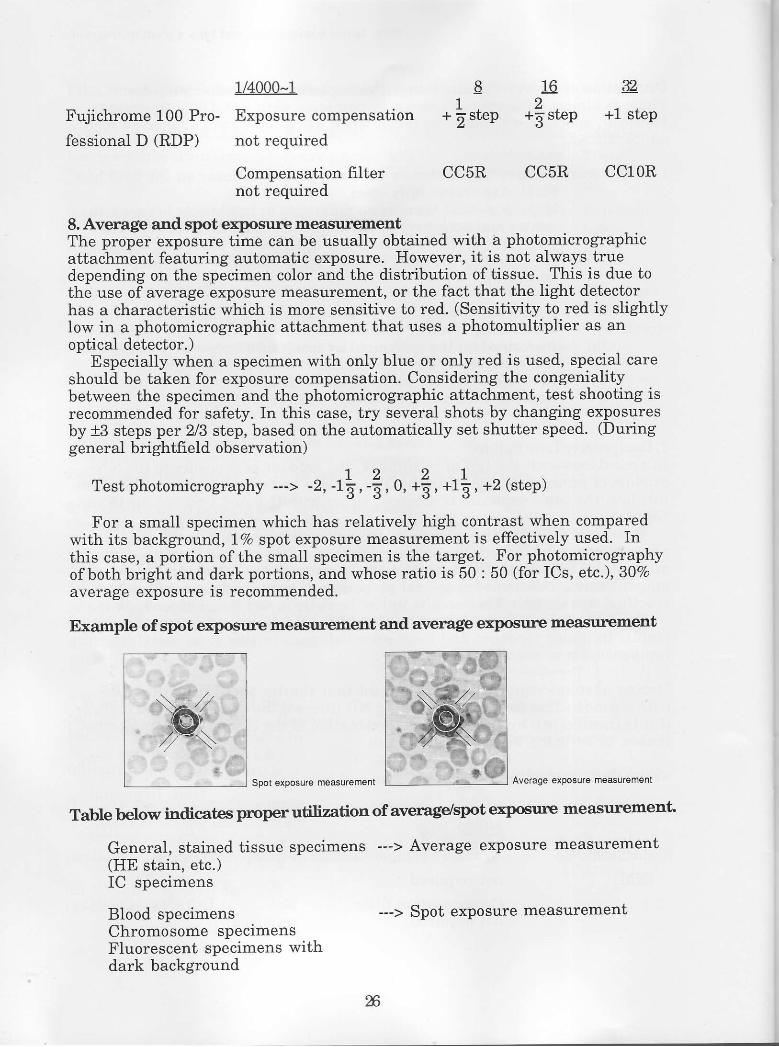
For a small specimen which has relatively high contrast when comparedwith its background, IVo spot exposure measurement is effectively used. Inthis case, a portion ofthe small specimen is the target. For photomicrographyofboth bright and dark portions, and whose ratio is 50 : 50 (for ICs, etc.), 307oaverage exposure is recommended.
Example of spot exlrosune measurement and average exposrure measurement
XSpot exposlrre m€asuremenl Average exposure measurernent
Table below indicates prrop€r utilization of average/spot exposul€ measuremenf,.
General, stained tissue specimens ---> Average exposure measurement(HE stain, etc.)IC specimens
Blood specimensChromosome specimensFluorescent specimens withdark background
--> Spot exposure measurement
%

How to use a microscope and take a photomicrograph
9. Precautions during photomioography by different observation methods
a) Differential Interference Contrast (Nomarski) Observation
(1) Black-and-white frlm - Use GIF (exposure compensation not required)Film: Kodak, Technical Pan Film 2418 (ISO/ASA 100)
* Developing conditions: D-76, 20"C, 8 minutes
(2) Color filmInterference color: Gray sensitive - NCB-10, gV, CC5M compensation
\rnterference.",",,#1r"1'ff"X'�i5ffi il#iK:'i,tT9rE119+.-,-.Interference color: Blue - NCB-10, 9V
(3) Precautions during photomicrography(a) Since shutter speed is usually slow, take precautions against external
vibrations, especially when magnification is high. The use ofavibration-free table is recommended.
(b) Since dust in the optical system causes decreased EF values, whichlowers the contrast, complete cleaning must be performed. Remove theeyepiece, remove the Nomarski prism from the optical path and look atthe aperture, then you can see the dust shining.
(c) Air bubbles often enter during oil immersion of the condenser. Sinceair bubbles cause decreased EF values and lowered contrast, they mustbe removed before microscopy. To check for air bubbles, remove iheeyepiece and look at the aperture.
(d) When especially high resolution is required, the aperture should beopened 100%.
(e) Since the use of the field diaphragm is very effective for removal of flareduring DIC observation, it is recommended that the user stops downthe field diaphragm to the furthest point within the photographic area.This makes photomicrography with higher contrast possible.
b) Fluorescence Observation(1) It is recommended that you use highly sensitive film, ISO/ASA 400 for
example. However, films with higher sensitivity (more than ISO/ASA400) will cause grainy images.
(2) Exposure compensationIf the specimen is smallerexposure compensation is
For example:If the specimen size is about half ofthe lVo measurement area. makeunder exposure compensation by 1step.
than the lVo spot exposure measurement area,necessary to match the size of the specimen.
Specimen
Generally, with U. V. B. excitation, photomicrography can be doneproperly without exposure compensation. However, sharper coloring maybe obtainable by applying approx. -1 step exposure compensation, v/hich isparticularly effective for projection purposes using a reversal film.
For photomicrography with G excitation, however, underexposurecompensation of one step more than other excitations is recommended. Inother words, compensation rarill be 1 to 2 steps under normal exposure.
In fluorescent photomicrography, the status of the specimen and thestaining greatly influences the success of photomicrography. For safety, itis recommended that the user makes a few trial shots by making underexposure cornpensation in one step. (For example, 0, -1, -2)
3) To increase contrast, stop down the field diaphragm to the extent wherevignetting does not occur.
4) To achieve photomicrography without uneven illumination, it is necessaryto provide centering of the light source (Hg) correctly.
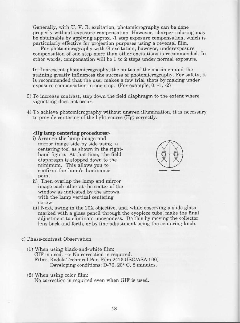
<Hg lamp centering procedures>i) Arrange the lamp image and
mirror image side by side using acentedng tool as shown in the right-hand figure. At that time, the fielddiaphragm is stopped down to theminimum. This allows you toconf-rrm the lamp's luminancepoint.
ii) Then overlap the lamp and mirrorimage each other at the center of thewindow as indicated by the arrows,with the lamp vertical centeringscrew.
iii) Next, swing in the 10X objective, and, while obsen ing a slide glassmarked with a glass pencil through the eyepiece tube, make the finaladjustment to eliminate u.nevenness. Do this by moving the collectorlens back and forth, or by fine adjustment using the centering knob.
c) Phase-contrast Observation
(1) When using black-and-white frlm:GIF is used. --> No colrection is required.Filrn: Kodak Technical Pan Film 2415 (ISO/ASA 100)
Developing conditions: D-76,20' C, 8 minutes.
(2) When using color fiim:No correction is required even when GIF is used.
%

d) Metallurgical Brightfield Observation
(1) Diaphragm
(a) Stopping down the field diaphragmas much as possible will remove flareeffectively.
In any photomicrographicsituation, stopping down the Fdiaphragm up to the picture frame,while looking through the finder,will make betterresults.
How to use a microscope and take a photomicrograph
When 35mm filrn is used.
(b) When performing photomicrography of specimens with unevensurface such as IC patterns, stopping down the diaphragm as muchas possible will create large depth of focus.-_ Although stopping down to 807o is generally recommended, thediaphragm can be stopped down to E\E;, if theie is no problem withregard to resolution.
(2) The specimen must be placed parallel to the stage surface. Otherwise,the entire viewdfield can not be focused perfectly, especially during highmagnification. If the specimen cannot be placed paiallel for somJreason' use of clay is also effective as shown in the frgure below.However, for more precision, use a special inclination stage.
(3) When us!1g a universal illuminator, be sure to remove the polarizingplate and Nomarski prism. (For prevention of inferior view due to dJubleilo.glg caused by the use of the Nomarski prism, and staining due tothe polarizing plate.) Also, be sure to insert an ND 82 filter slider forcompensating the optical path length and focusing of the F diaphragmrmage.
(4) When an M Plan 1X objective is used, be sure to use a polarizing plate inorder to remove flare. During color photomicrography, it is bettei to usea CC5M filter to correct the color tone ofthe polariiing plate.
m

e) Metallurgical Darkfreld Observation
(1) Aperture diaphragm and field diaphragmBoth diaphragms should be opened. If both diaphragms are stoppeddown, the viewfreld will be dark because the illumination does not coverthe viewfield and there will be a shortage oflight.
(2) Dust on the specimen is detected by its shine; it should be removed.
(3) Precautions during photomicrography
(a) Under this type of microscopy, shiny objects such as scratches areseen in a darkfreld. Therefore, exposure compensation is usuallynecessary.
spot measurement area
Bright part of specimen
For the specimen as described above, it is necessary to set tlne 7Vomeasurement mode and make a -1 step or -2 steps exposurecompensation. (The degree of correction is based on the ratio of thespecimen size to the size of the measurement area. If the ratio is 0.5,the correction value is -1 step.)
(b) Since the viewfield is dark, it is better to use film with a hieh ISO/ASAvalue.
(4) Although the BD Plan Achromat 60X, 100X objectives are provided with asafety scheme, their top lenses edge project out of the metal ornamentalring. Therefore, it will come in contact with the specimen if the stage isli{ted too far. Take care so that the lens is not broken.
30
Ornamental ring

How to use a microscope and take a photomicrograph
f) Metallurgical Nomarski Observation
(1) Photomicrographic conditions(a) Interference color: Gray sensitive - 9V, NCB-10, CCSM(b) Interference color: First order red (530nm) - 12V, No NCB-10, CC5M
or 9V; NCB-10, CCSM(c) When black ancl white film is used:
- GIF, 12V (Max.)- Film: Kodak's Technical Pan Film 2415
(To increase contrast)
g) Stereoscopic Microscopes
(1) Halogen lamp - - 5.5V, NCB-10(2) Fiber illuminator - - Maximum voltage, with NCB-10(3) Fluorescent illunrinator - - No filter
Since the viewfield becomes light blue under (2) ancl (3), a compensationfilter is required.
Others
(a) Since zoom magnification is low overall and because of the eye's ilepth offocus, the image is liable to go out offocus. Therefore, the use ofafocusing magnifier is a must.
(b) The periphery of the viewfield can not be observed when zoommagnification less than 1X is used. (This is based on specifications andnot abnormal.)
(c) When a stereoscopic microscope is used, it is often a case that thespecimen is not necessarily flat. Therefore, be sure to check whether theentire viewfield is focused by looking through the finder.
3[

V. Microscope Cleaning and Storage
Inspection and cleaning of the optical system is particularly important, forboth photomicrography and observation.
When using a rnicroscope, always start with removing dust in the opticalsyslem.
1, D'ust clerning points
It is recommended that, as a rule, you always clean the seven points indicatedabove before using a rnicroscope.
Before working on these points, using a blower, blow off dust and other foreigrrmatter attached to the microscope, specifically:(1) binocular eyepiece tube, (2) stage surface, ancl (3) base surface.
n
How to use a microscope and take a photomicrograph
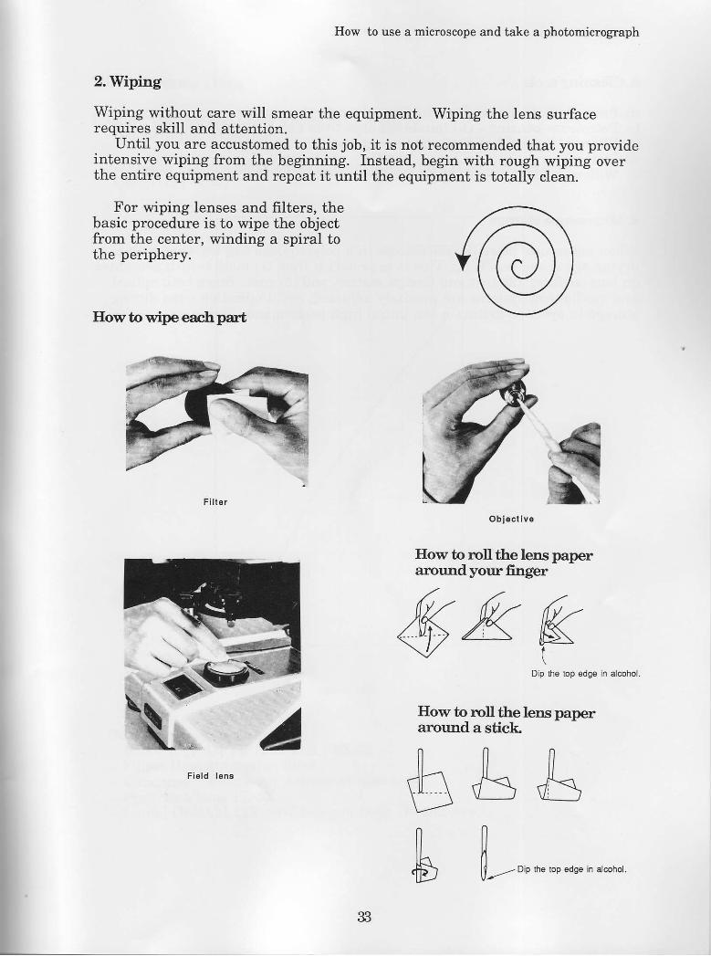
2.Wiping
Wiping without care will smear the equipment. Wiping the lens surfacerequires skill and attention.
Until you are accustomed to this job, it is not recommended that you provideintensive wiping from the beginning. Instead, begin with rough wiping overthe entire equipment and repeat it until the equipment is totally clean.
For wiping lenses and filters, thebasic procedure is to wipe the objectfrom the center, winding a spiral tothe periphery.
IIow to wipe eachpart
O b i € c t i v e
How to roll the lens pa.peraroundyourfinger
A
6. 6- i-1W>^ K
\ 7 (Dip the lop edge in alcohol.
How to rroll the lens paperalound a stick
b & &fi---- o, *" .o ",se in arcohor.
F i e l d l e n s

3. Qlsening tools
a) Pure alcohol - Lens, filter surface, glycerin cleaningb) Petroleum benzine - Oil immersed objectives and condensersc) Blower - Removal of dust and foreigrr matterd) Lens papere) Willow or cedar sticks - Used to wipe objectives by sharpening the edge.
4. Mimscope stomge
When not in use, place the microscope in a polyethylene bag together with adrying agent and seal it up. This is to protect it from (1) mold (which generateson lens surface), (2) dust and foreign matter, and (3) rust. Since both opticaland mechanical systems are precisely adjusted, avoid vibration even duringstorage in order to maintain the initial high performance.
v
How to use a microscope and take a photomicrograph
VLRefenenceData
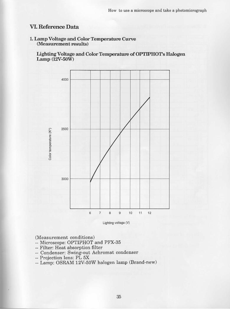
l. Tarnp Voltage and Color Temperature Curve(Measurement resulLs)
Lighting Voltage and ColorTemperature of OPTIPIIOTS Halogent arnp (12V.50W)
4000
8 9 1 0 1 1 1 2
Lighting voltage (V)
(Measurement conditions)-- Microscope: OPTIPHOT antl PFX-35- Filter: Heat absorption filter-- Condenser: Swing-out Achromat condenser- Projection lens: PL 5X- Lamp: OSRAM 12V-50W halogen lamp (Brand-new)
6- 3500
3000 /
35

2. 35mm Camera Optical Data
Resolving power:
Depth of focus:
Real field of view:
(Biological microscopes)
* DOF: Depth offocus on film plane
l"' - 2 x N . A .. nl"" - 2xN.A?_ "l2F;96,
a n - -P
(), = 0.55pm)f 6 = 0.05 Resolution on film 20/mm
-l
I n: Refractive index of objective side medium II n = 1 .0 Dry objective II n = 1 .52 Immersion objective -l
ObjectivesNumer ica l
apertureN . A .
Resolution€(pm J
CF PLprojection lens
masnification (X)
Totalmagnification
B(X)
DO FXt(!rm)
Actualviewfield
0 ( m m )
z
4x 0.13 2.L02.54
10IO
n16.3
,1 .)
2 .72 .2
10x 0.30 0.902.54b
&m
3 .1t . 71 . 10 .9
20x. 0.50 0.55z-54
m80
1001 . 1
0.870.540.43
40x 0.70 0.402.54
100160m
0.60.430.270.22
1OOx(o i l )
t .25 0.222.54
wM500
0.30.170.110.09
z
4x 0.20 1.402.54
10IO
n6 . 9
2.2
1Ox 0.45 0.60 45
%4m
r .41 . 71 .10.9
20x 0.75 0.402.54
5080
1000.5
0.870.540.43
40x 0.95 0.302.54
100160w
0.30.430.270.22
1OOx(o i l )
1.40 0.202.54
m400500
0 .20.170.110.09
36
How to use a rnicroscope and take a photonicrograph
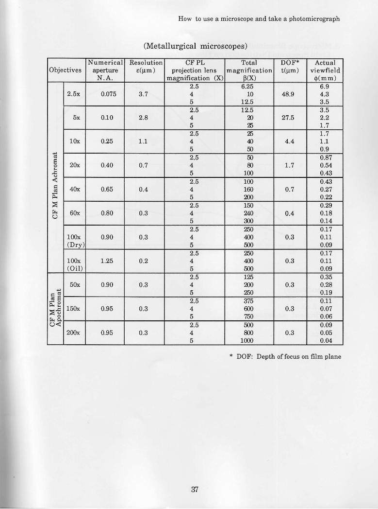
(Metallurgical microscopes)
ObjectivesNurnerical
apeftureN.A .
Resolution€(Pm)
CF PLprojection lens
maerrification (X)
Totalmagnification
B(X)
DOF*t(pn)
Actualviewfield
0 (mm)
6l
E()
2.5x 0.075 e n2.54o
6.2510
L2.548.9
6.94.33.5
5x 0.10 q 92.54D
L2.5n%
2753.52.21 .7
10x 0.25 1 . 12.54D
%050
4.41 .1 . 10.9
2A 0.40 0.72.54o
5080
1001 n
0.870.540.41
4Ox 0.65 0.42.54o
10016020t)
0.70.410.270.22
6Ox 0.80 0.32.54o
1502&300
0.40.290.180.14
100x(Drv)
0.90 0.32.54o
m4005m
0.3o.L70.110.09
1Oft(oi1)
t.25 0.22.54o
nrm5m
0.30.170.110.09
>lr r EO<
5Ox 0.90 0.32.54o
L%200m
0.30.350.280.19
150x 0.95 0.32.54o
J I O
6007il
0.30.110.070.06
2OOx 0.95 0.3
3' X,
4D
500800
10000.3
0.090.050.04
* DOF: Denth of focus on film olane
37
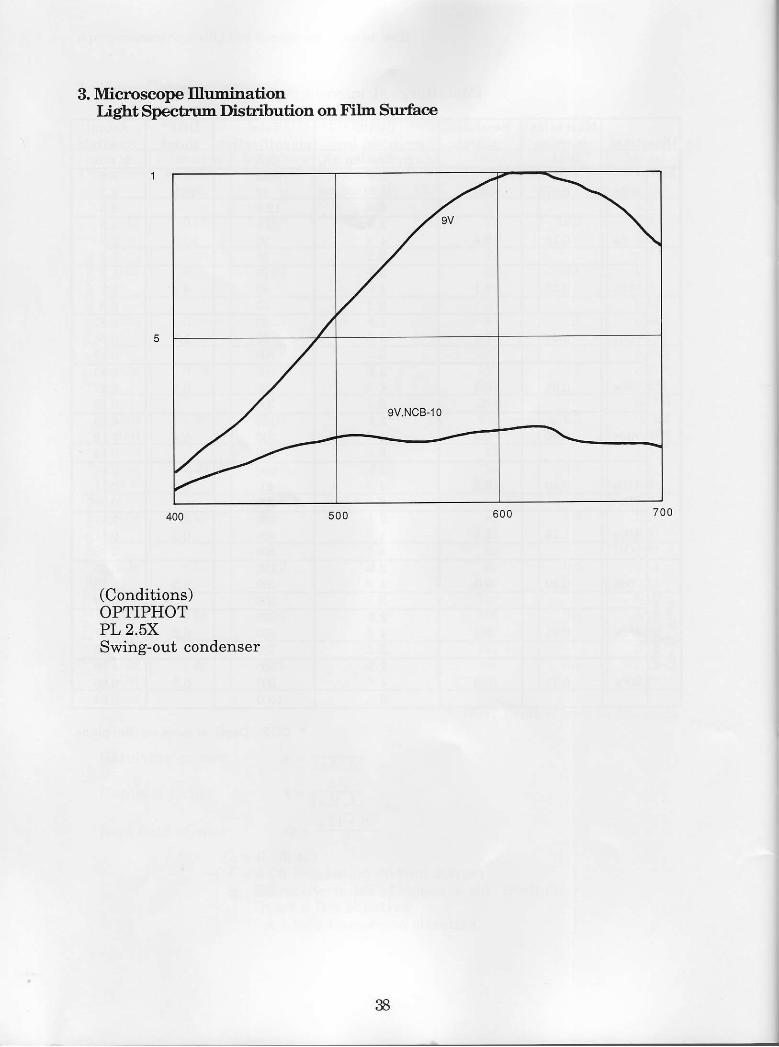
3. Miooscope IlluninationLigbt Specbum Dishibution on Fih Surface
400
(Conditions)OPTIPHOTPL 2.5XSwing-out condenser
500 600 700
,(
9V.NCB-10
I
38

NIKON CORPORATIONFuji Bldg., 2-3, Marunouchi 3'chome, Chiyoda'ku, Tokyo 100, JapanTel: 81-3-2161026 Telex: 22601 (NIKON J) Fax: 81 3 201-5856
Printed in Japan (8906-04)T 2CE-MYYH-]