Embed Size (px)
Citation preview

Manual Receiver GR-12+ 3xG Graupner HoTT 2. 4
Operating Instructions
33575 Receiver GR-12 SH +3xG HoTT33576 Receiver GR-12 +3xG HoTT33577 Receiver GR-12 +3xG+3A+ Vario
1. Notes...................................................................................................................... 32. Functions............................................................................................................... 52.1. Binding......................................................................................................... 52.1.1 Binding multiple receivers...................................................................................52.2. Fail-Safe function............................................................................................... 52.3 Range-checking........................................................................................... 63. Receiver.................................................................................................................. 73.1. Connections.................................................................................................. 73.2. Receiver set-up menu........................................................................................ 83.3. Free mixers....................................................................................................... 93.4 Assigning the gyro axes......................................................................................114. Programming the gyro settings...............................................................................134.1. Programming PID correction..............................................................................134.2. Programming the factors....................................................................................144.2.1 Programming, transmitter with proportional controls............................................144.2.2 Programming, transmitter without proportional controls.......................................154.3 Initialising the gyro.......................................................
..................................................................................................................................15
5. Firmware update 166. Conformity declaration / Guarantee / Manufacturer’s declaration / Disposal..18
Manual Receiver GR-12+ 3xG Graupner HoTT 2. 4 2
• Customer supportWe are happy to assist you with any question by e-mail or phone.Customer service hours are from 9 am to 5 pm PST (Pacific Standard Time) during the workweek, Monday through Friday.E-mailed questions will be answered as soon as possible
• Online SupportPlease visit us at www.openhobbby.com, to stay up to date with the latest software, firmware and product information.
• A/S SupportDuring the warranty period, we can repair this product at no cost in the event that it has become faulty under normal operating conditions.For non-functional products that are past the expiration date of the warranty or have been improperly used, we would be happy to repair this product for an appropriate amount of cost to the consumer.
• Warranty informationRefer to the WARRANTY CARD in the Package
3245 University Ave, Suite 1520, San Diego, CA 92104, United States of AmericaPhone: +1 855-5-RCisHoTT ( +1 855-572-4746) Fax: +1 855-546-0350 E-mail: [email protected]©2014 Graupner/SJ USA – OPENHOBBY LLC. The HoTT trademark is used with permission of SJ Inc. 4386066
• SUPPORT AND SERVICE
• OPENHOBBY A/S CENTER
MANY THANKSfor deciding to purchase the Graupner HoTT 2.4 system. Please read right through these operating instructions before you attempt to install and operate the Graupner HoTT 2.4 system.
• three axes
• • Excellent stabilisation for smooth, accurate manoeuvres•
• • Simple gyro assignment procedure• Facility to adjust parameters using HoTT telemetry• Altitude sensor for vario and altimeter function (Order No. 33577)
1. APPROVED USAGEThe receiver is intended exclusively for use in radio-controlled models. Any other usage is prohibited, and may result in damage to the receiver or model, and serious personal injury. We grant no guarantee and accept no liability for any type of use outside the stipulated range.Not suitable for children under fourteen years. This receiver is not a toy!
The receiver is also equipped with a telemetry function which is only available in combination with a Graupner HoTT 2.4 system. If you do not own a Graupner HoTT 2.4 system, the receiver will not work.Please start by reading through the whole instructions before you attempt to install and operate the receiver.These operating instructions are an integral part of the product. They contain important notes on operating and handling the receiver. For this reason please store the operating instructions in a safe place, and pass them on to the new owner if you ever dispose of the product. Failure to observe the operating instructions and safety notes invalidates the guarantee.Here at Graupner we are constantly working on the further development of all our products; for this reason we are obliged to reserve the right to introduce changes to the set contents in form, technology and features.Please understand that we will not countenance claims resulting from information and illustrations in these operating instructions.Please store the operating instructions in a safe place for future reference!
1.1 SAFETY NOTES
KEY TO THE SYMBOLS
Caution!This symbol alerts you to prohibited actions which must be observed at all times. Any failure to observe the prohibited action indicated in this way may prevent the equipment working, and endanger the safety of the operator.Caution!This symbol alerts you to information which must be observed at all times. Any failure to observe the information indicated in this way may prevent the equipment working properly, and endanger the safety of the operator.
This symbol indicates information which should always be observed in order to ensure that the equipment operates reliably.
Manual Receiver GR-12+ 3xG Graupner HoTT 2. 4 3
4 Manual Receiver GR-12+ 3xG Graupner HoTT 2. 4
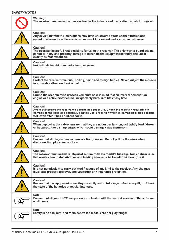
SAFETY NOTESWarning!
Caution!Any deviation from the instructions may have an adverse effect on the function and operational security of the receiver, and must be avoided under all circumstances.
Caution!The operator bears full responsibility for using the receiver. The only way to guard against personal injury and property damage is to handle the equipment carefully and use it exactly as recommended.
Caution!Not suitable for children under fourteen years.
Caution!Protect the receiver from dust, soiling, damp and foreign bodies. Never subject the receiver to excessive vibration, heat or cold.
Caution!During the programming process you must bear in mind that an internal combustion engine or electric motor could unexpectedly burst into life at any time.
Caution!Avoid subjecting the receiver to shocks and pressure. Check the receiver regularly for damage to the case and cables. Do not re-use a receiver which is damaged or has become wet, even after it has dried out again.
Caution!When deploying the cables ensure that they are not under tension, not tightly bent (kinked) or fractured. Avoid sharp edges which could damage cable insulation.
Caution!
disconnecting plugs and sockets.
Caution!The receiver must not make physical contact with the model’s fuselage, hull or chassis, as this would allow motor vibration and landing shocks to be transferred directly to it.
Caution!. Any changes
invalidate product approval, and you forfeit any insurance protection.
Caution!
the state of the batteries at regular intervals.
Note!Ensure that all your HoTT components are loaded with the current version of the software at all times.
Note!Safety is no accident, and radio-controlled models are not playthings!
1.2 GENERAL NOTES• The receiver’s integral gyros are very fast, high-resolution components. This means that you
should always use high-speed digital servos wherever possible, so that the gyro’s corrective signals are converted directly and accurately into servo movement; this helps to prevent the model oscillating.
• Keep all servo extension leads as short as possible.• When switching on or adjusting the radio control system, it is essential to keep the transmitter
aerial at least 15 cm from the receiver aerial(s). If the transmitter aerial is too close to the receiver aerials, the receiver will be swamped and the red LED on the receiver will light up. The transmitter
the radio control system reverts to fail-safe mode. If this should happen, increase the distance until the audible warning ceases, and the blue transmitter LED lights up constantly once more. The red LED on the receiver should now be off.
2. FUNCTIONS
2.1. BindingThe Graupner HoTT 2.4 receiver must be “bound” to “its” Graupner HoTT 2.4 RF module (transmitter) before a radio link can be created between them; this process is known as “binding”. Binding is only necessary once for each combination of receiver / RF module, so the binding procedure described below only needs to be repeated if you add more receivers. However, binding can be repeated at any time if you wish; for example, if you switch transmitters. This is the procedure in detail:• Binding is only possible if the receiver has not been linked with a bound transmitter since being
switched on (red LED lights); press the SET button to set the receiver to BIND mode.• If you have already bound a receiver to the transmitter, and wish to bind the receiver to a new
model memory, this is the procedure:• Switch the transmitter’s RF section off in the “Basic model settings” menu.• Switch the receiver on, and press the SET button to set it to Bind mode.• Initiate binding in the transmitter’s “Basic model settings” menu.• The red receiver LED should go out within about ten seconds. If it does, the binding process has
been completed successfully.• Your transmitter / receiver combination is now ready for use.• However, if the red LED continues to glow, then the binding process has failed. If this should
happen, repeat the whole procedure.
2.1.1. Binding multiple receivers per modelIf necessary it is also possible to bind more than one receiver to a particular model. First bind each receiver individually as described earlier.When the system is actually in use, the receiver which was last bound acts as the Master unit, and any telemetry sensors installed in the model must be connected to this receiver, as only the Master receiver transmits the data to the ground using the downlink channel. The second - and any other - receivers operate in Slave mode, in parallel with the Master receiver, with the downlink channel switched off.The channel mapping function of HoTT telemetry also allows the control functions to be divided up amongst multiple receivers, or alternatively the same control function to be assigned to multiple receiver outputs. For example, this is useful if you wish to actuate each aileron with two servos instead of just one.
2.2. Fail-Safe functionIn the receiver’s default state, all connected servos remain in their last valid position (“Hold” mode) if a fail-safe situation should arise. In fail-safe mode the red LED on the receiver lights up, and the transmitter generates an audible alert by beeping at a rate of around one per second.You can exploit the safety potential of this option by at least setting the throttle position (for internal-combustion powered models) to Idle, or the motor function (electric-powered models) to “Stop”, or “Hold” for a model helicopter, if a fail-safe event should occur. These settings ensure that the model is less
personal injury.Read the operating instructions supplied with your radio control system for more details.The gyro system remains active in a fail-safe situation.
Manual Receiver GR-12+ 3xG Graupner HoTT 2. 4 5

2.3 Range-checkingThe range of your Graupner HoTT 2.4 system can be checked as described in the following instructions. We recommend that you ask a friend to help you with the procedure.
• Switch the radio control system on, and wait until the red LED on the receiver goes out. The servo movements can now be observed.
• receiver aerials are at least 15 cm above the ground. It may be necessary to pack up the model to achieve this for the period of the range-check.
• Hold the transmitter away from your body at hip-level. Don’t point the transmitter aerial straight at the model; instead rotate or angle the aerial tip in such a way that it is vertical when you operate the transmitter controls.
• Select range-check mode, as described in the transmitter instructions.• Walk away from the model, moving the transmitter sticks. If you detect an interruption in the radio
link at any time within a distance of about 50 m, see if you can reproduce the problem.•
range when potential interference is present.• Walk further away from the model to the point where full control is no longer possible.• At this point you should manually switch off range-check mode.
The model should now respond to the controls again. If this is not 100% the case, do not use the system. Contact the Graupner Service Centre in your locality and ask their advice.
on the ground.
2.4 INSTALLATION IN THE MODELThe gyro-receiver must be installed “square” relative to the model, i.e. at right-angles to the aircraft’s longitudinal axis, otherwise the gyros will be unable to function as intended (Order No. 33577 must also be horizontal relative to the fuselage centreline to allow the accelerometer to work correctly).
OK
Also required for Order No. 33577
OK
6 Manual Receiver GR-12+ 3xG Graupner HoTT 2. 4
3. RECEIVER
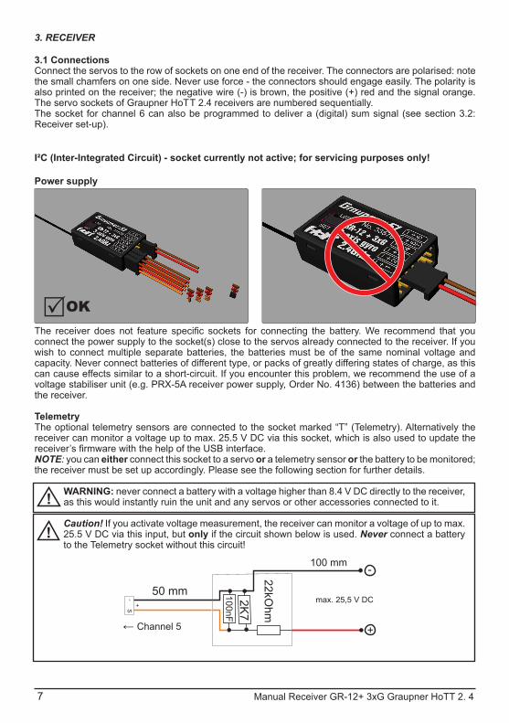
3.1 ConnectionsConnect the servos to the row of sockets on one end of the receiver. The connectors are polarised: note the small chamfers on one side. Never use force - the connectors should engage easily. The polarity is also printed on the receiver; the negative wire (-) is brown, the positive (+) red and the signal orange. The servo sockets of Graupner HoTT 2.4 receivers are numbered sequentially.The socket for channel 6 can also be programmed to deliver a (digital) sum signal (see section 3.2: Receiver set-up).
I²C (Inter-Integrated Circuit) - socket currently not active; for servicing purposes only!
Power supply
connect the power supply to the socket(s) close to the servos already connected to the receiver. If you wish to connect multiple separate batteries, the batteries must be of the same nominal voltage and capacity. Never connect batteries of different type, or packs of greatly differing states of charge, as this can cause effects similar to a short-circuit. If you encounter this problem, we recommend the use of a voltage stabiliser unit (e.g. PRX-5A receiver power supply, Order No. 4136) between the batteries and the receiver.
TelemetryThe optional telemetry sensors are connected to the socket marked “T” (Telemetry). Alternatively the receiver can monitor a voltage up to max. 25.5 V DC via this socket, which is also used to update the
NOTE: you can either connect this socket to a servo or a telemetry sensor or the battery to be monitored; the receiver must be set up accordingly. Please see the following section for further details.
WARNING: never connect a battery with a voltage higher than 8.4 V DC directly to the receiver, as this would instantly ruin the unit and any servos or other accessories connected to it.
Caution! If you activate voltage measurement, the receiver can monitor a voltage of up to max. 25.5 V DC via this input, but only if the circuit shown below is used. Never connect a battery to the Telemetry socket without this circuit!
OK
max. 25,5 V DC
← Channel 5
Manual Receiver GR-12+ 3xG Graupner HoTT 2. 4 7

8 Manual Receiver GR-12+ 3xG Graupner HoTT 2. 4
PROGRAMMING THE GENERAL RECEIVER SETTINGS:The receiver can be programmed using a suitable HoTT transmitter or the SMART-BOX (Order No. 33700).
3.2 RECEIVER SET-UP MENUThe receiver set-up menu appears in the “Telemetry” menu under SETTINGS / DISPLAYS; alternatively - if you are using a SMART-BOX - under SETTING & DATAVIEW. The method of accessing this menu is described in the operating instructions supplied with your transmitter or the Smart-Box.
Display Explanation SettingsRECEIVER 1.0
1.0 -
ALARM VOLT. Alarm threshold for the receiver’s low voltage warning (or voltage measurement)
2.5 - 24.0 VDefault setting: 3.8 V
ALARM TEMP. Receiver overheating warning 50 - 80° CDefault setting: +70° C
Max. height Order No. 33577 only, with integral vario: maxi-mum altitude
0 - 2500 m in 25 m increments
ZYKLUS Cycle time (frame rate) in ms 10 / 20 ms
SUMD an K6 Digital sum signal at channel 6 Yes / No
K5 Use of channel 5: servo, telemetry sensor or volt-age measurement
Servo, Sensor, SpannungWerkseinstellung: Servo
LANGUAGE Select menu language German, English, French, Italian or Spanish
Low-voltage warning (ALARM VOLT): if the receiver voltage or the external voltage connected to channel 5 falls below the set value, a low-voltage warning is generated by the transmitter’s RF module in the form of the “general alarm tone”: a regular beeping at a rate of about one per second; alternatively the speech output message “Receiver voltage”.
Temperature warning (ALARM TEMP): if the receiver temperature exceeds the set temperature threshold, a warning is generated by the transmitter’s RF module in the form of the “general alarm tone”: a regular beeping at a rate of about one per second; alternatively the speech output message “Receiver temperature”.
Maximum height (Max. height) - Order No. 33577 with integral vario only: at this point you can enter a maximum altitude, at which an alarm is triggered, either via the transmitter’s RF module in the form of the “general alarm tone”: a regular beeping at a rate of about one per second; alternatively the speech output message “Height”. Note: the model’s actual height is adopted as zero when the receiver is switched on; the indicated height is therefore the altitude relative to the launch point.
Cycle time (CYCLE): if your system is used exclusively with digital servos, you can set a cycle time (frame rate) of 10 ms at this point. If your system includes some or all analogue servos, you should always select 20 ms, as many analogue servos cannot process the higher frame rate, and may respond by “jittering” or “growling”.HoTT sum signal (SUMD): if you activate the digital sum signal at channel 6, a sum signal containing
RECEIVER 1.0 < > >ALARM VOLT: ALARM TEMP: max altitude: >Period:>SUMD at K6: K5: LANGUAGE:
3.8V70°C125m10msNo
SERVOenglish
Manual Receiver GR-12+ 3xG Graupner HoTT 2. 4 9
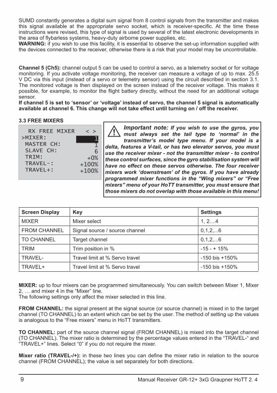
SUMD constantly generates a digital sum signal from 8 control signals from the transmitter and makes
instructions were revised, this type of signal is used by several of the latest electronic developments in
WARNING: if you wish to use this facility, it is essential to observe the set-up information supplied with the devices connected to the receiver, otherwise there is a risk that your model may be uncontrollable.
Channel 5 (Ch5): channel output 5 can be used to control a servo, as a telemetry socket or for voltage monitoring. If you activate voltage monitoring, the receiver can measure a voltage of up to max. 25.5 V DC via this input (instead of a servo or telemetry sensor) using the circuit described in section 3.1. The monitored voltage is then displayed on the screen instead of the receiver voltage. This makes it
sensor.If channel 5 is set to ‘sensor’ or ‘voltage’ instead of servo, the channel 5 signal is automatically available at channel 6. This change will not take effect until turning on / off the receiver.
3.3 FREE MIXERSImportant note: If you wish to use the gyros, you must always set the tail type to ‘normal’ in the transmitter’s model type menu. If your model is a
delta, features a V-tail, or has two elevator servos, you must use the receiver mixer - not the transmitter mixer - to control these control surfaces, since the gyro stabilisation system will have no effect on these servos otherwise. The four receiver mixers work ‘downstream’ of the gyros. If you have already programmed mixer functions in the “Wing mixers” or “Free mixers” menu of your HoTT transmitter, you must ensure that those mixers do not overlap with those available in this menu!
Screen Display Key SettingsMIXER Mixer select 1, 2....4
FROM CHANNEL Signal source / source channel 0,1,2,...6
TO CHANNEL Target channel 0,1,2,...6
TRIM Trim position in % -15 - + 15%
TRAVEL- Travel limit at % Servo travel -150 bis +150%
TRAVEL+ Travel limit at % Servo travel -150 bis +150%
MIXER: up to four mixers can be programmed simultaneously. You can switch between Mixer 1, Mixer 2, … and mixer 4 in the “Mixer” line.The following settings only affect the mixer selected in this line.
FROM CHANNEL: the signal present at the signal source (or source channel) is mixed in to the target channel (TO CHANNEL) to an extent which can be set by the user. The method of setting up the values is analogous to the “Free mixers” menu in HoTT transmitters.
TO CHANNEL: part of the source channel signal (FROM CHANNEL) is mixed into the target channel (TO CHANNEL). The mixer ratio is determined by the percentage values entered in the “TRAVEL-“ and “TRAVEL+” lines. Select “0” if you do not require the mixer.
Mixer ratio (TRAVEL-/+):channel (FROM CHANNEL); the value is set separately for both directions.
RX FREE MIXER < > >MIXER: MASTER CH: SLAVE CH: >TRIM:>TRAVEL-: TRAVEL+:
116
+0%+100%+100%

Manual Receiver GR-12 + 3xG Graupner HoTT 2. 4 10
Programming examples:
V-tail with rudder differential RX FREE MIXER < > >MIXER: MASTER CH: SLAVE CH: >TRIM:>TRAVEL-: TRAVEL+:
134
+0%+100%+100%
RX FREE MIXER < > >MISCHER: MASTER CH: SLAVE CH: >TRIM:>TRAVEL-: TRAVEL+:
243
+0%-60%+100%
RX FREE MIXER < > >MIXER: MASTER CH: SLAVE CH: >TRIM:>TRAVEL-: TRAVEL+:
344
+0%+100%+60%
Differential is not normally necessary with this tail type. Mixer 3 is not required if you do not need rudder differential, and TRAVEL- for mixer 2 must then be set to -100%.Alternatively you may prefer to carry out the programming using the transmitter menu. A ‘Rudder elevator’ mixer can be set up at the transmitter instead of ‘Free mixer 3’ at the receiver; the mixer should be set up asymmetrically, e.g. +30%, -30%. This option frees up one mixer at the receiver.
Delta with aileron differential (1 aileron) RX FREE MIXER < > >MISCHER: MASTER CH: SLAVE CH: >TRIM:>TRAVEL-: TRAVEL+:
123
+0%+100%+60%
RX FREE MIXER < > >MISCHER: MASTER CH: SLAVE CH: >TRIM:>TRAVEL-: TRAVEL+:
232
+0%-100%-100%
RX FREE MIXER < > >MISCHER: MASTER CH: SLAVE CH: >TRIM:>TRAVEL-: TRAVEL+:
322
+0%+60%
+100%
In this example aileron differential is set to 40%. Alternatively you may prefer to carry out the programming using the transmitter menu. An ‘Aileron elevator’ mixer can be set up at the transmitter instead of ‘Free mixer 3’ at the receiver; the mixer should be set up asymmetrically, e.g. +30%, -30%. This option frees up one mixer at the receiver.
Two elevator servos(channel 6 for the second elevator servo)
RX FREE MIXER < > >MISCHER: MASTER CH: SLAVE CH: >TRIM:>TRAVEL-: TRAVEL+:
138
+0%+100%+100%
Manual Receiver GR-12+ 3xG Graupner HoTT 2. 4 11
Programming example:
RX FREE MIXER < > >MIXER: MASTER CH: SLAVE CH: >TRIM:>TRAVEL-: TRAVEL+:
112
+0%+100%+100%
RX FREE MIXER < > >MISCHER: MASTER CH: SLAVE CH: >TRIM:>TRAVEL-: TRAVEL+:
215
+0%-100%-100%
Programming example:
RX FREE MIXER < > >MISCHER: MASTER CH: SLAVE CH: >TRIM:>TRAVEL-: TRAVEL+:
112
+0%+100%+100%
RX FREE MIXER < > >MISCHER: MASTER CH: SLAVE CH: >TRIM:>TRAVEL-: TRAVEL+:
213
+0%-100%-100%
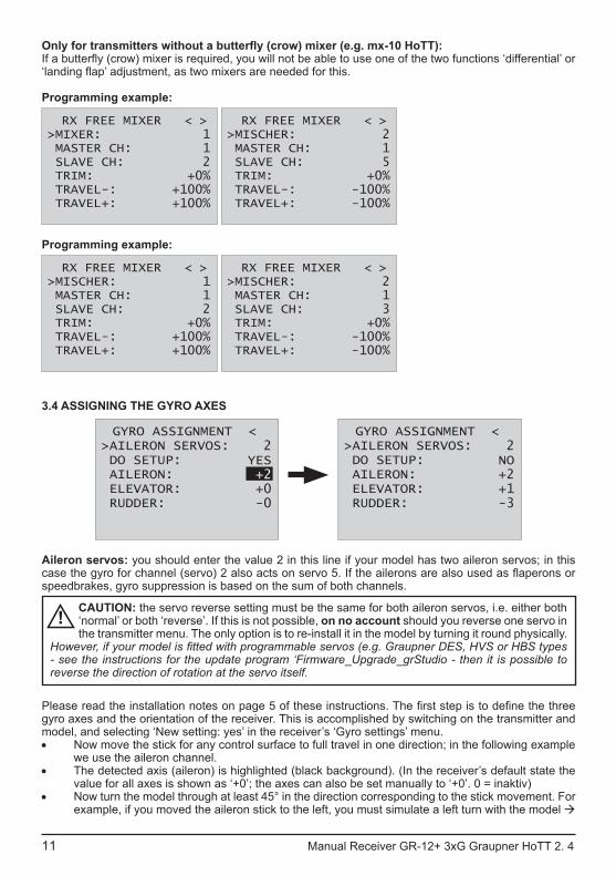
3.4 ASSIGNING THE GYRO AXES
Aileron servos: you should enter the value 2 in this line if your model has two aileron servos; in this
speedbrakes, gyro suppression is based on the sum of both channels.
CAUTION: the servo reverse setting must be the same for both aileron servos, i.e. either both ‘normal’ or both ‘reverse’. If this is not possible, on no account should you reverse one servo in the transmitter menu. The only option is to re-install it in the model by turning it round physically.
- see the instructions for the update program ‘Firmware_Upgrade_grStudio - then it is possible to reverse the direction of rotation at the servo itself.
gyro axes and the orientation of the receiver. This is accomplished by switching on the transmitter and model, and selecting ‘New setting: yes’ in the receiver’s ‘Gyro settings’ menu.• Now move the stick for any control surface to full travel in one direction; in the following example
we use the aileron channel.• The detected axis (aileron) is highlighted (black background). (In the receiver’s default state the
value for all axes is shown as ‘+0’; the axes can also be set manually to ‘+0’. 0 = inaktiv)• Now turn the model through at least 45° in the direction corresponding to the stick movement. For
example, if you moved the aileron stick to the left, you must simulate a left turn with the model
GYRO ASSIGNMENT < >AILERON SERVOS: DO SETUP: AILERON: ELEVATOR: RUDDER:
2YES+2+0-0
GYRO ASSIGNMENT < >AILERON SERVOS: DO SETUP: AILERON :>ELEVATOR:>RUDDER:
2NO+2+1-3
12 Manual Receiver GR-12+ 3xG Graupner HoTT 2. 4
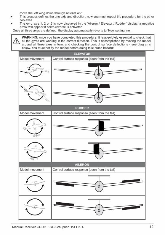
move the left wing down through at least 45°.•
two axes.• The gyro axis 1, 2 or 3 is now displayed in the ‘Aileron / Elevator / Rudder’ display; a negative
WARNING: once you have completed this procedure, it is absolutely essential to check that all the gyros are working in the correct direction. This is accomplished by moving the model
ELEVATORModel movement Control surface response (seen from the tail)
RUDDERModel movement Control surface response (seen from the tail)
AILERONModel movement Control surface response (seen from the tail)
Manual Receiver GR-12+ 3xG Graupner HoTT 2. 4 13
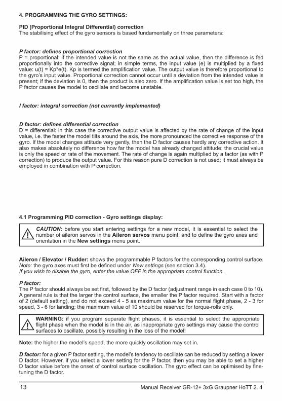
4. PROGRAMMING THE GYRO SETTINGS:
PID (Proportional Integral Differential) correctionThe stabilising effect of the gyro sensors is based fundamentally on three parameters:
P = proportional: if the intended value is not the same as the actual value, then the difference is fed
the gyro’s input value. Proportional correction cannot occur until a deviation from the intended value is
P factor causes the model to oscillate and become unstable.
I factor: integral correction (not currently implemented)
D = differential: in this case the corrective output value is affected by the rate of change of the input value, i.e. the faster the model tilts around the axis, the more pronounced the corrective response of the gyro. If the model changes attitude very gently, then the D factor causes hardly any corrective action. It also makes absolutely no difference how far the model has already changed attitude; the crucial value is only the speed or rate of the movement. The rate of change is again multiplied by a factor (as with P correction) to produce the output value. For this reason pure D correction is not used; it must always be employed in combination with P correction.
4.1 Programming PID correction - Gyro settings display:
CAUTION: before you start entering settings for a new model, it is essential to select the number of aileron servos in the Aileron servosorientation in the New settings menu point.
Aileron / Elevator / Rudder: shows the programmable P factors for the corresponding control surface.Note: New settings (see section 3.4).If you wish to disable the gyro, enter the value OFF in the appropriate control function.
P factor:
A general rule is that the larger the control surface, the smaller the P factor required. Start with a factor
speed, 3 - 6 for landing; the maximum value of 10 should be reserved for torque-rolls only.
WARNING:
surfaces to oscillate, possibly resulting in the loss of the model!
Note: the higher the model’s speed, the more quickly oscillation may set in.
D factor: for a given P factor setting, the model’s tendency to oscillate can be reduced by setting a lower D factor. However, if you select a lower setting for the P factor, then you may be able to set a higher
tuning the D factor.

14 Manual Receiver GR-12+ 3xG Graupner HoTT 2.4
Note: the standard P and D values should cause the gyros to correct the model’s attitude quickly when
with the default settings, the value should be raised; on the other hand, if the model oscillates (wave-like
If your transmitter has spare proportional controls, you can use them to adjust the values while the
4.2 Programming the factors
4.2.1 Programming, transmitter with proportional controlsIf your HoTT transmitter is equipped with proportional controls, it is also possible to adjust the P and
proportional controls (e.g. the sliders on the mc-20) to any channel in the range 5 to 16 (in this example channel 9); now you can alter the P factor (and the D factor) using these controls. In each case the current values are shown in brackets.
Procedure, using the ailerons as an example:
• Move the cursor to the appropriate line, in this case “Ail” for aileron.• • Select the appropriate channel, and save the setting with pressing the SET button again• move the corresponding proportional control to alter the factor (adjustment range 0 - 10; 0 means no gyro correction for that axis).• You can also adopt this factor directly by pressing the left
button < or the right button >. This frees up the channel previously occupied by the proportional control, so that it can be used for some other purpose, e.g. for elevator or rudder.
• Move on to elevator and / or rudder, and select the channel and factor (you can either select the same channel, in order to alter all the axes simultaneously, or different channels, allowing you to program the axes individually).
• Move the cursor to the Factor line, where you can also change the P factor for aileron, elevator and rudder with priority (adjustment range up to 200%).
• Move the cursor to the D factor line, where you can alter the D factor for aileron, elevator and rudder with priority using a proportional control (adjustment range up to 200%; channel value -100% equates to a factor of 0%, channel value 0% equates to 100%, and +100% equates to 200%). This makes it a very easy matter to match the gyro’s corrective effect to the model’s airspeed. In particular, higher gyro gain can be used for the landing approach - without the need
• is achieved without the model oscillating.
• optimum setting for that axis, rather than for several axes simultaneously.
GYRO SETTINGS < > >AILERON: >ELEVATOR:>RUDDER: COEFF.: COEFF. D:
(2)K9(3)K8
6(44%)K10
(140%)K11

Manual Receiver GR-12+ 3xG Graupner HoTT 2. 4 15
4.2.2. Programming, transmitter without proportional controls
• Move the cursor to the appropriate line, in this case “Ail” for aileron.• appropriate value (1 - 10 of OFF), then press the SET button to save it.• )stniop gnitrats rof noitces rotcaf P ees( eulav wol a tceles tsriF
If gyro stabilisation is not
until the level of correction is as required; if the model already oscillates, reduce the value step by step.
• Do not select a channel (Ch5 - Ch16); this function is only relevant to transmitters with proportional controls.
• Move on to elevator or rudder and select the desired value (or OFF).• Leave the settings for “Factor” and “Factor D” at OFF.•
optimum setting for that axis, rather than for several axes simultaneously.
Once you have found the optimum settings, you can set up a transmitter switch to control the gyro, i.e. for switching between gain settings. For example, you could assign a three-position switch to “Factor” and “Factor D”, and then use it to switch the values between 0% (OFF), 100% and 200%.
It is possible to use a channel to control the factor value by setting up control settings, but only if the transmitter is an MX20 / MC20 or MC32; please see the instructions supplied with your transmitter and refer to the “Transmitter control settings” and “Flight phase settings” menu points for more information.
4.3 Initialising the gyroAfter switching on the model of the gyroscope is immediately active but not yet initialized. To initialize it,
the successful initialization, the end of the calibration, only then the model may be moved again.All sticks are to be kept strictly in neutral!
WARNING: during the initialisation phase the gyro detects the model’s neutral attitude, and for
and could even crash!During the initialisation phase the receiver also detects the centre points of the individual control channels; this information is used for gyro suppression. Gyro suppression reduces the stabilising
gyro is completely disabled.
GYRO SETTINGS < > >AILERON: >ELEVATOR:>RUDDER: COEFF.: COEFF. D:
246
AusAus
16 4 .2 TToH renpuarG Gx3 +21-RG revieceR launaM
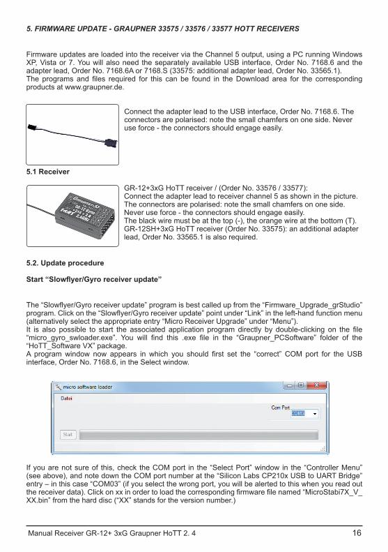
5. FIRMWARE UPDATE - GRAUPNER 33575 / 33576 / 33577 HOTT RECEIVERS
Firmware updates are loaded into the receiver via the Channel 5 output, using a PC running Windows XP, Vista or 7. You will also need the separately available USB interface, Order No. 7168.6 and the adapter lead, Order No. 7168.6A or 7168.S (33575: additional adapter lead, Order No. 33565.1).
products at www.graupner.de.
Connect the adapter lead to the USB interface, Order No. 7168.6. The connectors are polarised: note the small chamfers on one side. Never use force - the connectors should engage easily.
5.1 Receiver
GR-12+3xG HoTT receiver / (Order No. 33576 / 33577):Connect the adapter lead to receiver channel 5 as shown in the picture. The connectors are polarised: note the small chamfers on one side. Never use force - the connectors should engage easily.The black wire must be at the top (-), the orange wire at the bottom (T).GR-12SH+3xG HoTT receiver (Order No. 33575): an additional adapter lead, Order No. 33565.1 is also required.
5.2. Update procedure
(alternatively select the appropriate entry “Micro Receiver Upgrade” under “Menu”).
“HoTT_Software VX” package.
interface, Order No. 7168.6, in the Select window.
If you are not sure of this, check the COM port in the “Select Port” window in the “Controller Menu” (see above), and note down the COM port number at the “Silicon Labs CP210x USB to UART Bridge” entry – in this case “COM03” (if you select the wrong port, you will be alerted to this when you read out
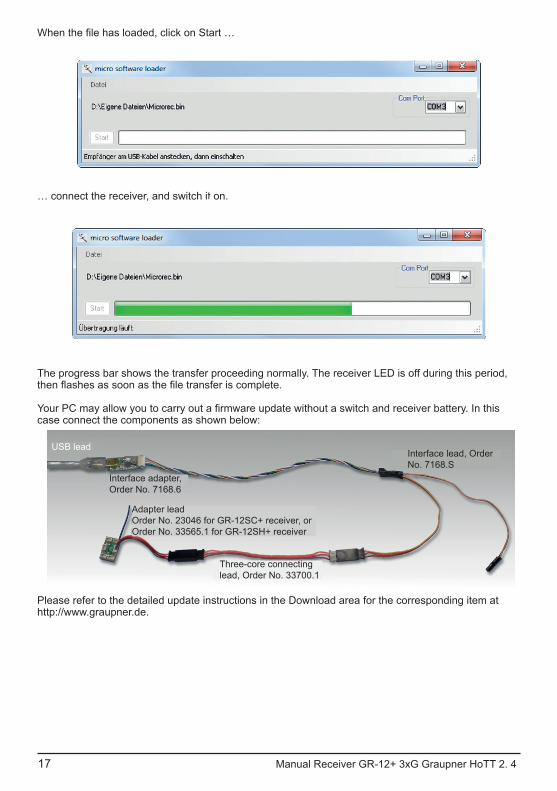
XX.bin” from the hard disc (“XX” stands for the version number.)
Manual Receiver GR-12+ 3xG Graupner HoTT 2. 4 17
… connect the receiver, and switch it on.
The progress bar shows the transfer proceeding normally. The receiver LED is off during this period,
case connect the components as shown below:
Please refer to the detailed update instructions in the Download area for the corresponding item at http://www.graupner.de.
USB lead
Interface adapter, Order No. 7168.6
Adapter leadOrder No. 23046 for GR-12SC+ receiver, orOrder No. 33565.1 for GR-12SH+ receiver
Three-core connecting lead, Order No. 33700.1
Interface lead, Order No. 7168.S
A
B
D
4 .2 TToH renpuarG Gx3 +21-RG
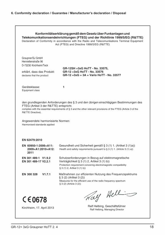
Konformitätserklärung gemäß dem Gesetz über Funkanlagen undTelekomunikationsendeinrichtungen (FTEG) und der Richtlinie 1999/5/EG (R&TTE)Declaration of Conformity in accordiance with the Radio and Telecomunikations Terminal Equipment
Act (FTEG) and Directive 1999/5/EG (R&TTE)
Graupner/SJ GmbHHenriettenstraße 96D-73230 Kirchheim/Teck
erklärt, dass das Produkt:declares that the product
Geräteklasse: 1Equipment class
den grundlegenden Anforderungen des § 3 und den übrigen einschlägigen Bestimmungen des FTEG (Artikel 3 der R&TTE) entspricht. complies with the essential requirements of § 3 and the other relevant provisions of the FTEG (Article 3 of theR&TTE Directive).
Angewendete harmonisierte Normen:Harmonised standards applied
EN
EN 62479:2010
60950-1:2006+A11:2009+A1:2010+A12:2011
EN 301 489-1 V1.9.2EN 301 489-17 V2.2.1
EN 300 328 V1.7.1
0678
Health and safety requirements pursuant to § 3 (1) 1. (Article 3 (1) a))
Protection requirement concernig electromagnetic compatibility § 3 (1) 2, Artikel 3 (1) b))
Measures for the efficient use of the radio frequency spectrum § 3 (2) (Article 3 (2))
Kirchheim, 17. April 2013 Ralf Helbing, Geschäftsführer Ralf Helbing, Managing Director
Gesundheit und Sicherheit gemäß § 3 (1) 1. (Artikel 3 (1)a))
Schutzanforderungen in Bezug auf elektromagnetische Verträglichkeit § 3 (1) 2, Artikel 3 (1) b))
Maßnahmen zur effizienten Nutzung des Frequenzspektrums § 3 (2) (Artikel 3 (2))
GR-12SH +3xG HoTT - No. 33575, GR-12 +3xG HoTT - No. 33576 GR-12 +3xG + 3A + Vario HoTT - No. 33577
18
6. Conformity declaration / Guarantee / Manufacturer’s declaration / Disposal
19 GR-12+ 3xG Graupner HoTT 2. 4
EN
1. This device complies with Part 15 of the FCC Rules. Operation is subject to the following two conditions:(1) This device may not cause harmful interference.(2) This device must accept any interference received, including interference that maycause undesired operation.2. Changes or modifications not expressly approved by the party responsible for compliancecould void the user‘s authority to operate the equipment.
• FCC Information
• FCC Statement
This equipment has been tested and found to comply with the limits for a Class B digitaldevice, pursuant to Part 15 of the FCC Rules. These limits are designed to provide reasonableprotection against harmful interference in a residential installation. This equipmentgenerates uses and can radiate radio frequency energy and, if not installed and used inaccordance with the instructions, may cause harmful interference to radio communications.However, there is no guarantee that interference will not occur in a particular installation.If this equipment does cause harmful interference to radio or television reception,which can be determined by turning the equipment off and on, the user is encouraged totry to correct the interference by one or more of the following measures:- Reorient or relocate the receiving antenna.- Increase the separation between the equipment and receiver.- Connect the equipment into an outlet on a circuit different from that to which the receiver is connected.- Consult the dealer or an experienced radio/TV technician for help.
This equipment complies with FCC radiation exposure limits set forth for an uncontrolled environment. This equipment should be installed and operated with minimum distance of 20 cm between the radiator and your body.
• NOTE
• FCC radiation exposure statement
VIRONMENTAL PROTECTION NOTES
The presence of this symbol on a product, in the user instructions or the packaging, means that you must not dispose of that item, or the electronic components contained within it, in the ordinary domestic waste when the product comes to the end of its useful life.
The correct method of disposal is to take it to your local collection point for recycling electrical and electronic equipment.
Individual markings indicate which materials can be recycled and re-used. You can make an important contribution to the protection of our shared environment by re-using the product, recycling the basic materials or re-processing redundant equipment in other ways.
Dry cells and rechargeable batteries must be removed from the device and taken separately to a suitable battery disposal centre.
In the case of RC models electronic components such as servos, receiver or speed controller must be removed from the product, and taken separately to the appropriate collection point for electrical waste.
Product: 33575 GR-12SH+3xG- FCC ID: SNL-16006000- FCC 47 CFR PART 15C
Product: 33576, GR-12+3xG- FCC ID: SNL-16005400- FCC 47 CFR PART 15C
Product: 33577, GR-12+3xG+3A+Vario- FCC ID: SNL-16005500- FCC 47 CFR PART 15C