Embed Size (px)
Citation preview
Joint Report Prepared under the JRC – ECCS cooperation agreement for the evolution of Eurocode 3
(programme of CEN / TC 250)
Editors: G. Sedlacek, M. Géradin, A. Pinto, H. Varum
EUR 24286 EN - 2010
Hot-dip-zinc-coating of prefabricatedstructural steel components
M. Feldmann, T. Pinger, D. Schäfer, R. Pope, W. Smith, G. Sedlacek
Background document in support to the implementation, harmonization andfurther development of the Eurocodes


The mission of the JRC-IPSC is to provide research results and to support EU policy-makers in their effort towards global security and towards protection of European citizens from accidents, deliberate attacks, fraud and illegal actions against EU policies. European Commission Joint Research Centre Institute for the Protection and Security of the Citizen Contact information Address: Joint Research Centre, ELSA Unit, TP 480, 21027 Ispra (Va), Italy E-mail: [email protected] Tel.: +39 (0332) 78 9989 Fax: +39 (0332) 78 9049 http://ipsc.jrc.ec.europa.eu/ http://www.jrc.ec.europa.eu/ The European Convention For Constructional Steelwork (ECCS) is the federation of the National Associations of Steelwork Industries. The aim of ECCS is to promote the use of steelwork in the construction sector by the development of technical and promotional information. The ECCS covers a worldwide network of partners in the Steel Industry: Producers, Fabricators, Contractors and Experts, Universities and Research Institutes. http://www.steelconstruct.com/ Contact information Address: Mies-van-der-Rohe-Straße 1, D-52074 Aachen E-mail: [email protected] Tel.: +49 241 80 25177 Fax: +49 241 80 22140 http://www.stb.rwth-aachen.de Legal Notice Neither the European Commission nor any person acting on behalf of the Commission is responsible for the use which might be made of this publication.
Europe Direct is a service to help you find answers to your questions about the European Union
Freephone number (*):
00 800 6 7 8 9 10 11
(*) Certain mobile telephone operators do not allow access to 00 800 numbers or these calls may be billed.
A great deal of additional information on the European Union is available on the Internet. It can be accessed through the Europa server http://europa.eu/ JRC 56810 EUR 24286 EN ISBN 978-92-79-15237-5 ISSN 1018-5593 DOI 10.2788/73644 Luxembourg: Office for Official Publications of the European Communities © European Union, 2010 © European Convention for Constructional Steelworks, 2010 Reproduction is authorised provided the source is acknowledged Printed in Italy


Hot-dip-zinc-coating of prefabricated structural steel components
1
Acknowledgements
This report gives a survey on the state of the art concerning „Liquid metal assisted cracking“ of prefabricated structural steel components in the hot zinc bath and conclusions for a quantitative assessment procedure to avoid such cracking. It has been prepared on the basis of various sources: - RFCS-CR-03021 Research project: “Failure mechanisms during Galvanizing”, - Reports from research projects funded by Arbeitsgemeinschaft industrieller
Forschung (AiF) No. 14545 N/1 and 265 ZBG/1, - Research reports from various origins mentioned in the bibliography, - Industry Guidance’s in UK, Austria, Japan, Canada and Germany, - DASt-Richtlinie 022: Hot-dip zinc coating of prefabricated steel components, - Numerous discussions held with representatives of Regulatory Bodies, industry
and research institutes, - Several doctoral thesis´ mentioned in the bibliography, - Contributions of the ad-hoc group with stakeholders at JRC in Ispra to agree on
the preparation of the report, - VDI-Richtlinie bzgl. Flüssigmetallversprödung beim Verzinken. All these valuable contributions are gratefully acknowledged. The preparation of the report was accompanied by an ad-hoc group which met at JRC in Ispra on 19th of January 2009 and at CEN MC in Brussels on 26th of February. Members of this ad-hoc group were: M. Géradin Joint Research Centre of the European Commission (JRC) A. Pinto JRC G. Tsionis JRC P. Özdemir JRC A. Da Costa CEN-Management Centre J. A. Calgaro CEN/TC250 for Structural Eurocodes F. Bijlaard CEN/TC250/SC3 for EN 1993 G. Sedlacek CEN/TC 250 (Convenor of the meeting) R. Pope CEN/TC135 for EN 1090 W. Smith CEN/TC262 for EN 1461 and EN 14713 V. Bergmann European Convention for Constructional Steel (ECCS) and
Deutscher Stahlbau Verband (DSTV) V. Hüller Deutscher Ausschuß für Stahlbau (DASt) B. Donnay European Steel Producers/Arcelor Mittal G. Axmann European Steel Producers/Arcelor Mittal M. Cook European General Galvanizers Association (EGGA) C. Leighfield EGGA A. Mohrenschildt EGGA M. Huckshold Gemeinschaftsausschuss Verzinken (GAV)/EGGA M. Feldmann RWTH Aachen D. Schäfer RWTH Aachen Thanks to all of them for their fruitful works and contributions M. Feldmann G. Sedlacek

Hot-dip-zinc-coating of prefabricated structural steel components
3
Preface
(1) Hot-dip-zinc-coating of steel components is an adequate measure for a reliable
protection against corrosion of steel components that might impact durability and sustainability.
(2) EN 1090, i.e. the standard for the delivery of prefabricated steel components and
the execution of steel components and works, addresses zinc-coating. The EN-Standards for the zinc-coating process as EN ISO 1461 and EN ISO 14713 are also referred to in this code.
(3) Cracking of steel under the corrosion attack by liquid zinc in the zinc bath has
been observed since the 1930´s and has been the concern of various research projects. The problem seemed to have been mastered for the usual design of components and the usual coating technology applied for many years.
(4) Since 2000 with a peak in 2002, a more frequent occurrence of cracking and
larger sizes of cracks that could impair the safety of structures could be observed. Cracking happened in particular after zinc-coated components had been assembled on site and cracks opened under loading filled or covered with zinc. These observations were coincident with the production of larger sizes of steel components characterized by larger plate thicknesses, the use of new constituent materials of higher strength, the use of new zinc alloys and the application of various dipping processes.
(5) National and international research initiated for that purpose revealed that these
cracks could be attributed to liquid metal embrittlement (LME) in the hot-zinc bath. The existing codes and standards and also some industry guidance established so far in some countries (e.g. in UK, Austria, Japan) do not give comprehensive provisions to prevent the risk of LME, so that in some countries initiatives came up to develop, on the basis of the existing research results, quantitative assessment rules that could mirror the effects of the various parameters on the phenomenon.
(6) In view of the development of a consistent “European Standard Family”, and the
further harmonization of “National choices” in the single market for construction products and construction services there was the wish to channel these actions to achieve a common European procedure.
(7) To this end representatives of the main stakeholders and parties concerned:
- the European Commission represented by the Joint Research Centre in Ispra,
- the CEN-Management Centre, - CEN/TC250 for the structural Eurocodes, - CEN/TC135 for the delivery of prefabricated steel components and the
execution of components and works, - CEN/TC262 for zinc-coating process.

Hot-dip-zinc-coating of prefabricated structural steel components
4
and also industrial representatives of the European steel producers (Arcelor Mittal), steel fabricators (ECCS), zinc coaters (EGGA), and also research institutes (RWTH Aachen) met in Ispra on 19th January 2009 to agree on the preparation of a “JRC-Scientific and Technical Report” on “Hot-dip-zinc-coating of prefabricated structural steel components”.
(8) This report could be - in line with resolution No. 255 agreed at the CEN/TC250
meeting in Malta – a common basis for further CEN-actions in the various CEN-Technical Committees, and also serve in the meantime as a reference document for intermediate National actions.
Ispra, February 2010 J.A. Calgaro, F. Bijlaard, G. Sedlacek, CEN/TC250 R. Pope, CEN/TC135 W. Smith, CEN/TC262 M. Géradin, A. Pinto, H. Varum, JRC

Hot-dip-zinc-coating of prefabricated structural steel components
5
JRC-Scientific and Technical Report
Hot-dip-zinc-coating of prefabricated structural steel components
List of contents Acknowledgements ...................................................................................................................... 1 Preface ........................................................................................................................................... 3 List of contents .............................................................................................................................. 5 Executive Summary ..................................................................................................................... 7 1 Objective ................................................................................................................................. 9 2 Examples of cracks observed ............................................................................................ 11 3 Literature survey .................................................................................................................. 13 4 Examination of macroscopic cracks ................................................................................. 17 5 Conclusions for developing a quantitative assessment method to avoid cracking in
the zinc bath ......................................................................................................................... 19 6 Standard test for determining the strain capacity of steels in the hot-zinc bath ........ 21 7 Strain resistance of steel material from LNT-tests ......................................................... 25 8 Strain rate dependency from the LNT-test ...................................................................... 31 9 Stress-strain requirements ................................................................................................. 35
9.1 General ............................................................................................................... 35 9.2 Stationary strains from fabrication ...................................................................... 35 9.3 Instationary strains from dipping ........................................................................ 37 9.4 Superposition of stationary and instationary strains .......................................... 38 9.5 Conclusions from variation of detail and plate thickness ................................... 38
10 Limit state assessments based on equivalent plastic strains ....................................... 43 11 Validation of the strain-oriented assessment method.................................................... 47
11.1 General ........................................................................................................... 47 11.2 Structural components from car-parkings ....................................................... 47 11.3 Further prefabricated beams .......................................................................... 48 11.4 Prefabricated columns .................................................................................... 49 11.5 Latticed structures ........................................................................................... 50 11.6 Cold-formed components................................................................................ 51 11.7 Hollow section components ............................................................................ 52
12 Transfer of results based on equivalent plastic strains into engineering models for practical assessments ........................................................................................................ 53
13 Simplified engineering models for numerical assessment ............................................ 55 14 Introduction of Confidence zones ..................................................................................... 63 15 Classification system without numerical assessment .................................................... 67 16 Worked examples for using the classification method in section 15 ........................... 73
16.1 General ........................................................................................................... 73 16.2 Usual metal works ........................................................................................... 73 16.3 Detailed examples .......................................................................................... 75 16.4 Examples of choices made in the fabrication ................................................. 79
17 Procedure tests .................................................................................................................... 87 18 Supplementary rules for execution of hot-dip-zinc coating ........................................... 89
18.1 General ........................................................................................................... 89 18.2 Control of chemical composition of the zinc melt ........................................... 89
18.2.1 Relevant Standards .................................................................................. 89 18.2.2 Equipment, tools and sampling ................................................................ 89
Hot-dip-zinc-coating of prefabricated structural steel components
6
18.2.3 Method for analysis ................................................................................. 91 18.3 Non destructive testing procedures for zinc coated structural components .. 91
18.3.1 General .................................................................................................... 91 18.3.2 References to standards ........................................................................ 91 18.3.3 Test personal ........................................................................................... 92 18.3.4 Preparation of surface for testing ............................................................ 92 18.3.5 Testing equipment and means for testing ............................................... 92 18.3.6 Check of sufficient magnetizing of the testing system ............................ 92 18.3.7 Check of sufficient magnetizing for a project .......................................... 92 18.3.8 Means for testing ..................................................................................... 92 18.3.9 Visual evaluation...................................................................................... 93 18.3.10 Area to be tested ..................................................................................... 93 18.3.11 Limits for confidence ................................................................................ 93 18.3.12 Demagnetizing ......................................................................................... 93 18.3.13 Treatment of structural components with faults ...................................... 93 18.3.14 Documentation of the tests ...................................................................... 95
19 Conclusion ............................................................................................................................ 97 20 Literature ............................................................................................................................... 99

Hot-dip-zinc-coating of prefabricated structural steel components
7
JRC-Scientific and Technical Report
Hot-dip-zinc-coating of prefabricated structural steel components
Executive Summary (1) This JRC-Scientific and Technical Report gives information from pre-normative
research methods to avoid liquid metal assisted cracking of prefabricated structural components during zinc-coating in the liquid zinc melt that may impair the structural safety of structures in which the components are built in.
(2) This information provides a platform upon which further European design and
product specifications can be developed. It may in particular affect the further developments of EN 1993, EN 1090 and EN ISO 1461 and EN ISO 14713.
(3) This report gives the state of the art in understanding the mechanism of liquid
metal assisted cracking in the zinc bath and methods and models that may be used to avoid it.
(4) It could be a basis to propose rules for the design of steel components intended
to be hot-dip-zinc-coated in such a way that the design is consistent with execution rules for hot-dip-zinc-coating.
(5) The workability of the rules proposed for all metal works and steel works that are
fabricated under EN 1090 and galvanized according to the rules in this report is demonstrated by worked examples.

Hot-dip-zinc-coating of prefabricated structural steel components
9
1 Objective (1) This part of the JRC-Scientific and Technical Report deals with the phenomenon
of “Liquid metal assisted cracking” (LMAC) of prefabricated steel components that may occur during hot-dip-zinc-coating in the hot-zinc bath and may in case of sufficient sizes of the cracks infringe the safety of the structures, which the steel components are built in.
(2) Such serious cracks have been observed in particular after the year 2000, when
the chemical composition of the zinc alloys was changed, the size of the components was increased and the material strength was enhanced.
(3) Therefore, there is a need to inform on the cause of such cracks, to identify the
most relevant parameters for cracking and to develop methods to avoid such cracking.
(4) This information is a summary to give the state of the art on the issue. It is
addressed to: 1. the design of prefabricated steel components,
2. the delivery of constituent products (semi-finished products) for the fabrication of steel components,
3. the fabrication of steel components, 4. the hot-dip-zinc-coating of steel components and subsequent checks.
(5) Therefore this information provides a platform upon which further European
design and product specifications can be developed. It may affect the further developments of:
- EN 1993 for the preparation of the component specification (see EN 1090-
1, 3.1.1 and 3.1.2), - hEN 1090-1 to cover galvanizing as for welding, - EN ISO 1461 and EN ISO 14713.

Hot-dip-zinc-coating of prefabricated structural steel components
11
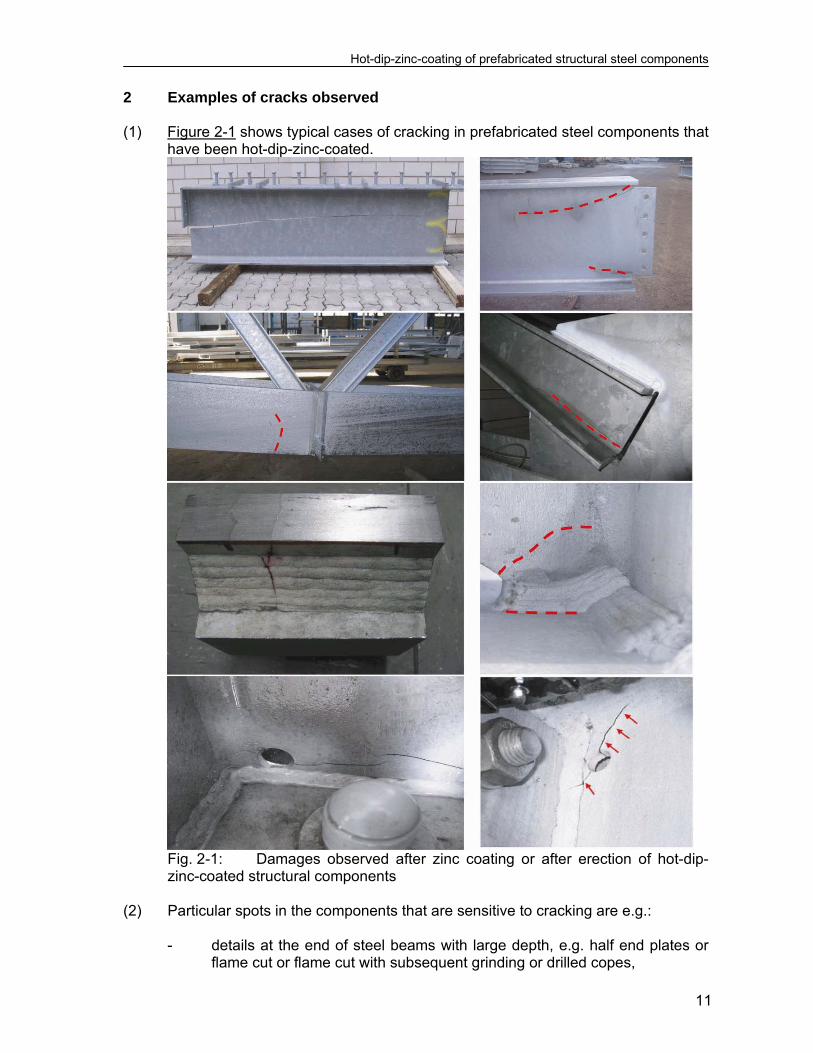
2 Examples of cracks observed (1) Figure 2-1 shows typical cases of cracking in prefabricated steel components that
have been hot-dip-zinc-coated.
Fig. 2-1: Damages observed after zinc coating or after erection of hot-dip-zinc-coated structural components
(2) Particular spots in the components that are sensitive to cracking are e.g.:
- details at the end of steel beams with large depth, e.g. half end plates or flame cut or flame cut with subsequent grinding or drilled copes,

Hot-dip-zinc-coating of prefabricated structural steel components
12
- the environment of welds in thick plates, - nodes of latticed structures, in particular those with hollow sections, - holes for the drainage of liquid zinc in corner areas.
(3) Crack sizes may be some millimetres to some decimetres; all usual steel grades,
e.g. S235, S355 and S460 have been affected by cracks. (4) Cracks often are only detected after the steel components have been built in a
structure and loaded, as the cracks in the steel components often are filled and covered with zinc. This also makes the detection of cracks after zinc-coating difficult and requires e.g. additional measures for magnet particle testing MT, as the usual application of EN 1290 would result in a reduced sensitivity for coat thicknesses 50 m.
(5) A peak in reports of cracking has occurred concerning work processed in the
period 2000 to 2006. These reports are associated principally with the use of higher concentrations of tin (Sn) together with other elements in the zinc melt in a number of countries during this period, to obtain thinner coats that could be better controlled and would give better appearance of the surfaces.
(6) The information given below therefore relate to the analysis and investigations
undertaken to find the causes of the crack damages most frequently observed that are related to Liquid Metal Embrittlement (LME) or Liquid Metal Assisted Cracking (LMAC) and result from a reduction of ultimate strain capacity of the steels in the hot-zinc bath.
(7) The phenomenon “Liquid metal embrittlement in the hot-zinc bath” is caused by
the contact of steel with the liquid-zinc alloy that causes a reaction between the zinc-melt and the steel material (Fe-Zn-reaction). This reaction and its intensity is controlled by various parameters as the composition of the zinc alloy, the steel material, the local strains and the time of exposure as well as the strain resistance of the steel.
(8) Hydrogen induced cracking, that could be excluded as a cause for the cracking
observed, is not dealt in this report. However, there may be cases where hydrogen induced cracking with subsequent liquid metal embrittlement may have been relevant.

Hot-dip-zinc-coating of prefabricated structural steel components
13
3 Literature survey (1) A literature survey for the period up to 2000 indicated that:
1. The phenomenon of Liquid Metal Embrittlement during hot-dip-zinc coating of steel has been dealt with since the 1930´s: - Works on other materials than steels, e.g. for stress corrosion of
aluminium alloys under attack of liquid metals as Mercury, Lithium, Gallium, Tin, Zinc, Lead had already revealed the importance of
- the chemical-physical affinity of the liquid metal with limited
solubility in the base metal, - the formation of eutectica with low solution temperature in
case of liquid metal alloys.
- Early works on steel materials were mainly related to specific questions of the durability of the kettles holding the zinc melt. Though the evaluation of such test-reports is difficult because of lack of suitable data in the documentations, some of the conclusions could be drawn as follows [25-27]:
a) Tests with steel specimen in tension in the liquid zinc bath,
see fig. 3-1 reveal a dependence between the stress-level, geometrical notch situation and time to fracture see for example fig. 3-2,
b) The frozen zinc layer forming in the beginning of dipping is torn by temperature induced strains and leads to further exposure of steel surfaces to liquid zinc thus explaining the time effect of exposure.
c) There are dependences between the time to fracture and the strain rate ε applied to the steel components: the smaller the strain rate, the greater the time to fracture.
Meßuhr: elongation measurement, Temperaturfühler: temperature measurements Gestänge: Application of tension force
Fig. 3-1 Test set-up [26]
Hot-dip-zinc-coating of prefabricated structural steel components
14
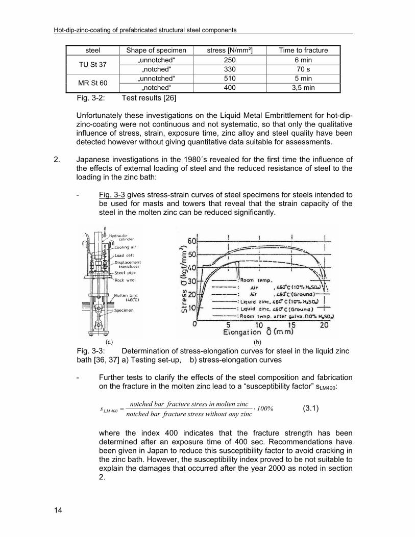
steel Shape of specimen stress [N/mm²] Time to fracture
TU St 37 „unnotched“ 250 6 min
„notched“ 330 70 s
MR St 60 „unnotched“ 510 5 min
„notched“ 400 3,5 min
Fig. 3-2: Test results [26]
Unfortunately these investigations on the Liquid Metal Embrittlement for hot-dip-zinc-coating were not continuous and not systematic, so that only the qualitative influence of stress, strain, exposure time, zinc alloy and steel quality have been detected however without giving quantitative data suitable for assessments.
2. Japanese investigations in the 1980´s revealed for the first time the influence of
the effects of external loading of steel and the reduced resistance of steel to the loading in the zinc bath:
- Fig. 3-3 gives stress-strain curves of steel specimens for steels intended to
be used for masts and towers that reveal that the strain capacity of the steel in the molten zinc can be reduced significantly.
Fig. 3-3: Determination of stress-elongation curves for steel in the liquid zinc
bath [36, 37] a) Testing set-up, b) stress-elongation curves - Further tests to clarify the effects of the steel composition and fabrication
on the fracture in the molten zinc lead to a “susceptibility factor” sLM400:
%100zincanywithoutstressfracturebarnotched
zincmolteninstressfracturebarnotcheds 400LM (3.1)
where the index 400 indicates that the fracture strength has been
determined after an exposure time of 400 sec. Recommendations have been given in Japan to reduce this susceptibility factor to avoid cracking in the zinc bath. However, the susceptibility index proved to be not suitable to explain the damages that occurred after the year 2000 as noted in section 2.

Hot-dip-zinc-coating of prefabricated structural steel components
15
- Japanese investigations have also been made to identify the stress-strain-development during dipping of steel components in the hot zinc bath.
Fig. 3-4 gives an example for the influence of the dipping speed on the
stress-intensity factor K of a plate with a crack. This shows that a low dipping speed effects an increase of K-requirement.
Fig. 3-4: Dependence of stress intensity factor K in dipping situation with
different dipping speeds a) test specimen, b) influence of dipping speed Also large scale tests with hollow sections for masts and towers were
carried out to determine the development of stresses and strains during the dipping process, fig. 3-5.
Fig. 3-5: Large scale tests for hollow sections for masts and towers
a) measuring devices, b) measured and calculated time history of stresses during dipping (v = 0.4 m/min) [43] These tests demonstrate:
- the development of stresses with characteristic alternating sign during the dipping process,
- the dependence of the maximum strain requirement on the dipping speed; the smaller the dipping speed the higher the strain occurring to be regarded as strain requirement.

Hot-dip-zinc-coating of prefabricated structural steel components
16
3. In conclusion, the works documented in literature until the year 2000 give
valuable information, mainly qualitatively or related to specific cases, so that the basis of a quantitative assessment to avoid liquid metal induced cracking in the zinc bath had not yet been developed at that time.
They give however already all key information necessary to identify the direction
of further research that has been carried out after the year 2000 to establish the basis for methods for such quantitative assessment.
Hot-dip-zinc-coating of prefabricated structural steel components
17
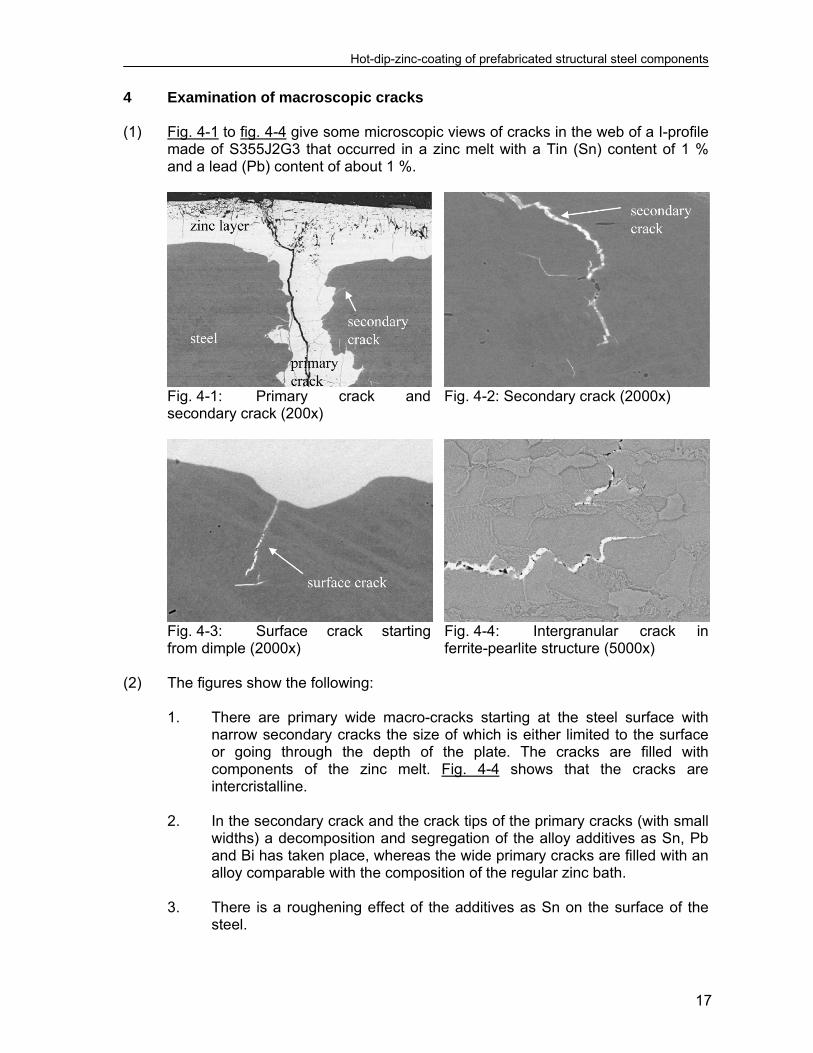
4 Examination of macroscopic cracks (1) Fig. 4-1 to fig. 4-4 give some microscopic views of cracks in the web of a I-profile
made of S355J2G3 that occurred in a zinc melt with a Tin (Sn) content of 1 % and a lead (Pb) content of about 1 %.
Fig. 4-1: Primary crack and secondary crack (200x)
Fig. 4-2: Secondary crack (2000x)
Fig. 4-3: Surface crack starting from dimple (2000x)
Fig. 4-4: Intergranular crack in ferrite-pearlite structure (5000x)
(2) The figures show the following:
1. There are primary wide macro-cracks starting at the steel surface with narrow secondary cracks the size of which is either limited to the surface or going through the depth of the plate. The cracks are filled with components of the zinc melt. Fig. 4-4 shows that the cracks are intercristalline.
2. In the secondary crack and the crack tips of the primary cracks (with small
widths) a decomposition and segregation of the alloy additives as Sn, Pb and Bi has taken place, whereas the wide primary cracks are filled with an alloy comparable with the composition of the regular zinc bath.
3. There is a roughening effect of the additives as Sn on the surface of the
steel.

Hot-dip-zinc-coating of prefabricated structural steel components
18
(3) The phenomena illustrated in fig. 4-1 to 4-4 are typical for liquid metal embrittlement, where a liquid metal phase, consisting of the components Fe, Zn and Sn or others penetrates into a solid metal, here steel, via the grain-borders.
(4) The physical mechanism for this is that the cohesion force between the grain
borders of the steel is smaller than the adhesion force of the liquid metal phase to the surface of the steel grains; hence the Gibbs-energy is reduced by the embrittlement.

Hot-dip-zinc-coating of prefabricated structural steel components
19
5 Conclusions for developing a quantitative assessment method to avoid cracking in the zinc bath
(1) From former investigations on LME performed in various countries and the
thorough examination of the cracks, the following conclusions could be drawn for the development of a quantitative assessment method to avoid cracking in the zinc bath:
1. Apparently the effect of liquid metal embrittlement of steel in the hot-zinc
alloy is a reduction of the ultimate strain capacity that should be quantified by a “standard test” that simulates the realistic behaviour of steel components in the zinc bath.
Such a test should give numerical results for a “strain resistance” R depending on several parameters that should be evaluated according to EN 1990-Annex D to obtain “characteristic resistance” values.
2. The “characteristic resistance” should be given for two design situations:
a) non-stationary or dipping phase: a design situation during the
dipping process when the strain requirements from non-stationary strains from the temperature differences (superimposed on stationary strains from the steel manufacturing process (rolling and straightening of the semi-finished product) and fabrication of the steel components (welding, bending, cutting, punching etc.)) are a maximum,
b) stationary or holding phase: a design situation after the full heating
of the steel component in the zinc bath, when the non-stationary strains have died down, however the strain capacity of the steel is further diminished due to the long exposure time (holding time).
3. The strain requirements E that could be used for a limit state assessment
RE εε (5.1)
should also be given as characteristic values and be determined by numerical simulations of the fabrication procedures and the dipping and holding process.
In consequence, both for the instationary design situation (dipping process) and for the stationary design situation (holding phase) the limit state equations read
RdEd εε (5.2)
where the index d designates “design values”, that are derived from “characteristic values” to obtain the required reliability.
4. This strain-oriented procedure is consistent with the assumptions made in
modern “damage theory” that applies in the upper-shelf region of the

Hot-dip-zinc-coating of prefabricated structural steel components
20
temperature-toughness diagram for ferrite steels. This theory is capable to simulate fracture-mechanics tests as well as the fracture behaviour of steels in monotonic and cyclic loading in the elastic and plastic range and also works with “equivalent plastic strains”.
Hot-dip-zinc-coating of prefabricated structural steel components
21
6 Standard test for determining the strain capacity of steels in the hot-zinc bath
(1) The “standard test“ shall provide characteristic values of “equivalent plastic
strain”-resistance in the zinc melt, that depends on the various process parameters, such as:
- composition of zinc melt and bath temperature, - steel quality, - microstructure and surface condition of steel product or of machined
surfaces, - strain rate.
(2) The standard test needs sufficiently small test specimens, however the results
should be independent on the scale and the particular loading condition of the test specimen and should be transferrable to any large scale structural component.
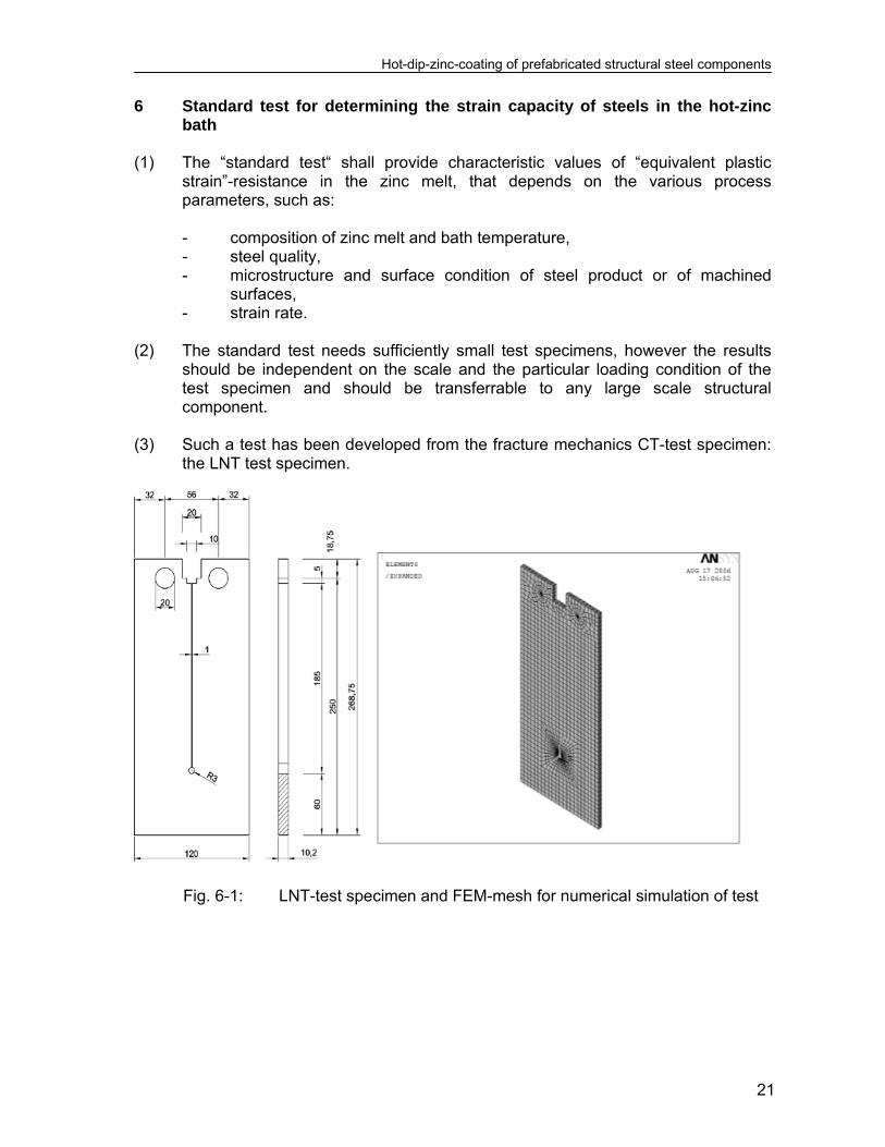
(3) Such a test has been developed from the fracture mechanics CT-test specimen:
the LNT test specimen.
Fig. 6-1: LNT-test specimen and FEM-mesh for numerical simulation of test

Hot-dip-zinc-coating of prefabricated structural steel components
22
Fig. 6-2: LNT-test setup and load application (4) Fig. 6-1 gives details of the LNT-test specimen with its dimensions in mm. It can
be dipped into the zinc melt and loaded horizontally by tensile forces with varying force-time characteristics, see fig. 6-2.
(5) The sharp crack tip of the CT-test specimen (in general obtained by applying
fatigue load cycles to these test specimens) is substituted by a drilled hole, the bottom of which is locally strained by the tension forces applied at the top of the specimen in such a way, that after a certain exposure time cracking at this hot-spot can be expected.
Fig. 6-3: Cracks at bottom of hole observed in tests and cracks observed in
practice (6) Fig. 6-3 gives the cracks observed in the test and cracks observed in practice at
a prefabricated steel component. (7) The local equivalent plastic strain at the bottom of the hole affected by the tensile
forces can be determined by FEM calculations

Hot-dip-zinc-coating of prefabricated structural steel components
23
dtplplvpl 3
2, (6.1)
(8) Fig. 6-4 gives an example of such calculations with the finite element mesh
adopted (Fig. 6-4a) and the plot of the plastic strains (Fig. 6-4b).
Fig. 6-4: FE-mesh and plot of equivalent plastic strains (9) Fig. 6-5 gives the relationship between the displacement in the line of load
application and the local equivalent plastic strain resulting from the loads.
Fig. 6-5: Master-curves for the determination of pl

Hot-dip-zinc-coating of prefabricated structural steel components
25
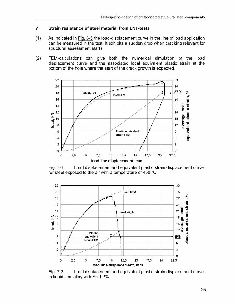
7 Strain resistance of steel material from LNT-tests (1) As indicated in Fig. 6-5 the load-displacement curve in the line of load application
can be measured in the test. It exhibits a sudden drop when cracking relevant for structural assessment starts.
(2) FEM-calculations can give both the numerical simulation of the load
displacement curve and the associated local equivalent plastic strain at the bottom of the hole where the start of the crack growth is expected.
0
2
4
6
8
10
12
14
16
18
20
22
0 2,5 5 7,5 10 12,5 15 17,5 20 22,5
load line displacement, mm
loa
d,
kN
0
3
6
9
12
15
18
21
24
27
30
33
ave
rag
e lo
ca
l eq
uiv
ale
nt
pla
sti
c st
rain
, %
Plastic equivalent strain FEM
load a0_05load FEM
27%
Fig. 7-1: Load displacement and equivalent plastic strain displacement curve
for steel exposed to the air with a temperature of 450 °C
0
2
4
6
8
10
12
14
16
18
20
22
0 2,5 5 7,5 10 12,5 15 17,5 20 22,5
load line displacement, mm
load
, kN
0
3
6
9
12
15
18
21
24
27
30
33a
vera
ge
loca
l p
last
ic e
qu
ival
en
t st
rain
, %
Plastic equivalentstrain FEM
load FEM
load a0_04
9%
%
Fig. 7-2: Load displacement and equivalent plastic strain displacement curve
in liquid zinc alloy with Sn 1,2%
Hot-dip-zinc-coating of prefabricated structural steel components
26
(3) Tests are run with a strain rate 4105 to simulate the design situation during dipping into the zinc bath with instationary stresses and strains.
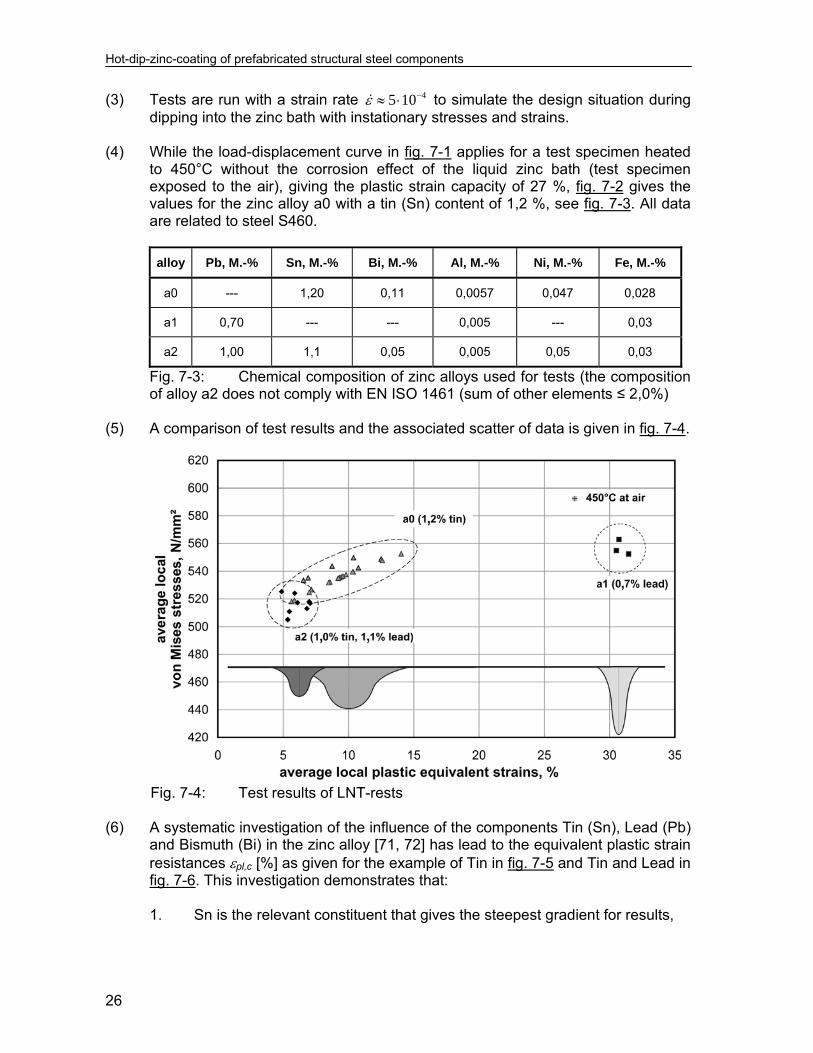
(4) While the load-displacement curve in fig. 7-1 applies for a test specimen heated
to 450°C without the corrosion effect of the liquid zinc bath (test specimen exposed to the air), giving the plastic strain capacity of 27 %, fig. 7-2 gives the values for the zinc alloy a0 with a tin (Sn) content of 1,2 %, see fig. 7-3. All data are related to steel S460.
alloy Pb, M.-% Sn, M.-% Bi, M.-% Al, M.-% Ni, M.-% Fe, M.-%
a0 --- 1,20 0,11 0,0057 0,047 0,028
a1 0,70 --- --- 0,005 --- 0,03
a2 1,00 1,1 0,05 0,005 0,05 0,03
Fig. 7-3: Chemical composition of zinc alloys used for tests (the composition of alloy a2 does not comply with EN ISO 1461 (sum of other elements ≤ 2,0%)
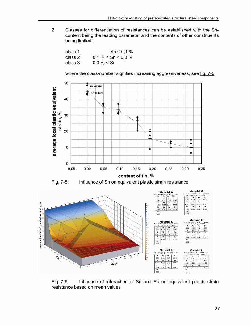
(5) A comparison of test results and the associated scatter of data is given in fig. 7-4.
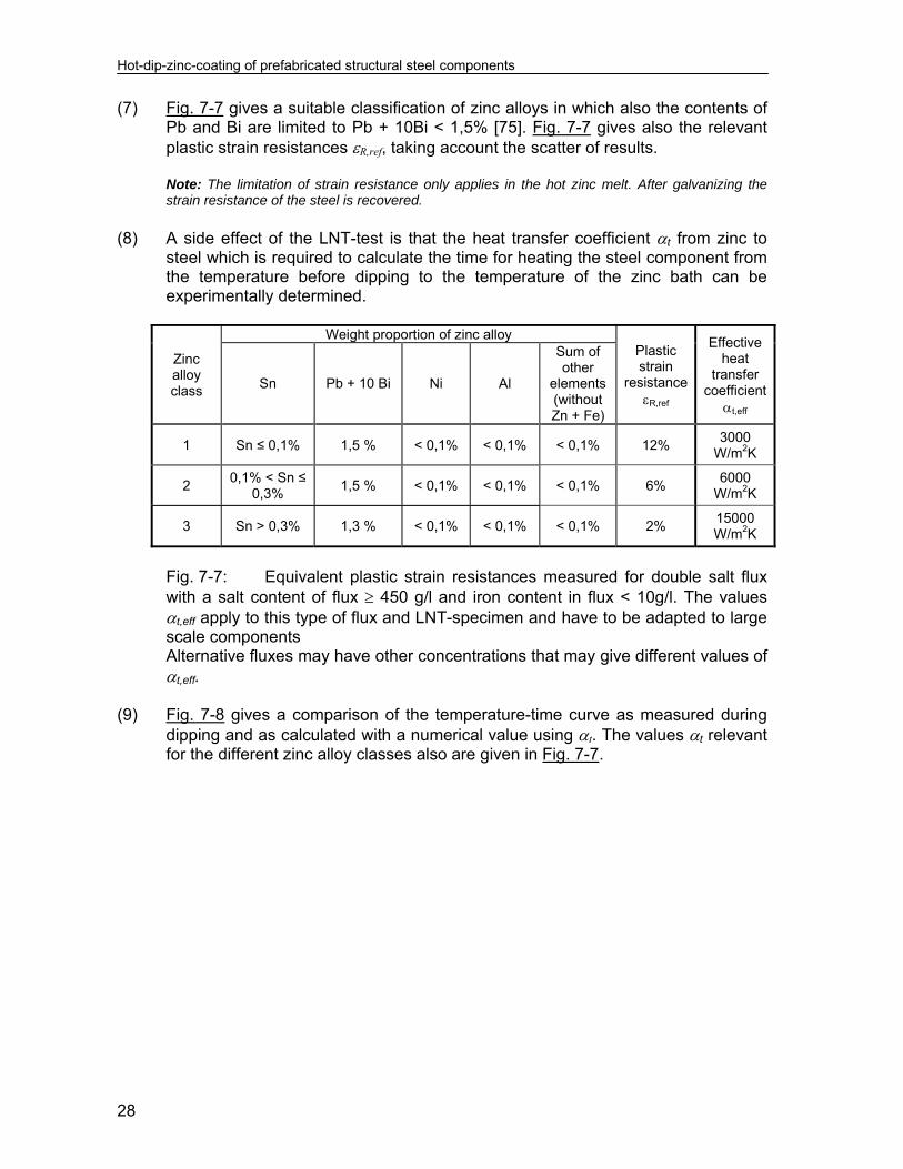
Fig. 7-4: Test results of LNT-rests (6) A systematic investigation of the influence of the components Tin (Sn), Lead (Pb)
and Bismuth (Bi) in the zinc alloy [71, 72] has lead to the equivalent plastic strain resistances pl,c [%] as given for the example of Tin in fig. 7-5 and Tin and Lead in fig. 7-6. This investigation demonstrates that:
1. Sn is the relevant constituent that gives the steepest gradient for results,
Hot-dip-zinc-coating of prefabricated structural steel components
27
2. Classes for differentiation of resistances can be established with the Sn-content being the leading parameter and the contents of other constituents being limited:
class 1 Sn 0,1 % class 2 0,1 % < Sn 0,3 % class 3 0,3 % < Sn
where the class-number signifies increasing aggressiveness, see fig. 7-5.
Fig. 7-5: Influence of Sn on equivalent plastic strain resistance
Fig. 7-6: Influence of interaction of Sn and Pb on equivalent plastic strain resistance based on mean values
Hot-dip-zinc-coating of prefabricated structural steel components
28
(7) Fig. 7-7 gives a suitable classification of zinc alloys in which also the contents of Pb and Bi are limited to Pb + 10Bi < 1,5% [75]. Fig. 7-7 gives also the relevant plastic strain resistances R,ref, taking account the scatter of results. Note: The limitation of strain resistance only applies in the hot zinc melt. After galvanizing the strain resistance of the steel is recovered.
(8) A side effect of the LNT-test is that the heat transfer coefficient t from zinc to
steel which is required to calculate the time for heating the steel component from the temperature before dipping to the temperature of the zinc bath can be experimentally determined.
Zinc alloy class
Weight proportion of zinc alloy Plastic strain
resistance R,ref
Effective heat
transfer coefficient
t,eff
Sn Pb + 10 Bi Ni Al
Sum of other
elements (without Zn + Fe)
1 Sn ≤ 0,1% 1,5 % < 0,1% < 0,1% < 0,1% 12% 3000
W/m2K
2 0,1% < Sn ≤
0,3% 1,5 % < 0,1% < 0,1% < 0,1% 6%
6000 W/m2K
3 Sn > 0,3% 1,3 % < 0,1% < 0,1% < 0,1% 2% 15000 W/m2K
Fig. 7-7: Equivalent plastic strain resistances measured for double salt flux with a salt content of flux 450 g/l and iron content in flux < 10g/l. The values t,eff apply to this type of flux and LNT-specimen and have to be adapted to large scale components Alternative fluxes may have other concentrations that may give different values of t,eff.
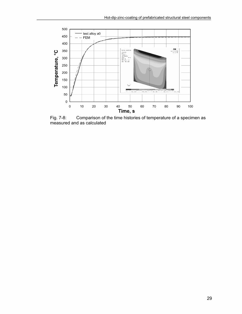
(9) Fig. 7-8 gives a comparison of the temperature-time curve as measured during
dipping and as calculated with a numerical value using t. The values t relevant for the different zinc alloy classes also are given in Fig. 7-7.
Hot-dip-zinc-coating of prefabricated structural steel components
29
Fig. 7-8: Comparison of the time histories of temperature of a specimen as
measured and as calculated

Hot-dip-zinc-coating of prefabricated structural steel components
31
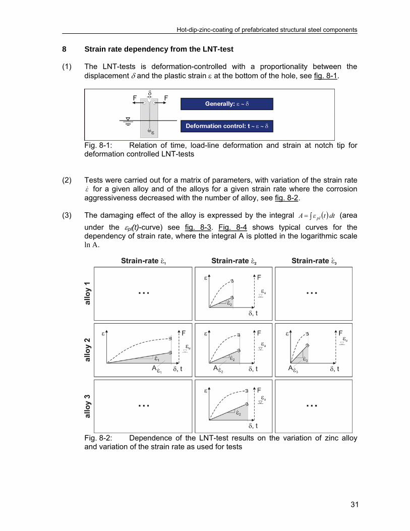
8 Strain rate dependency from the LNT-test (1) The LNT-tests is deformation-controlled with a proportionality between the
displacement and the plastic strain at the bottom of the hole, see fig. 8-1.
Fig. 8-1: Relation of time, load-line deformation and strain at notch tip for deformation controlled LNT-tests
(2) Tests were carried out for a matrix of parameters, with variation of the strain rate
ε for a given alloy and of the alloys for a given strain rate where the corrosion aggressiveness decreased with the number of alloy, see fig. 8-2.
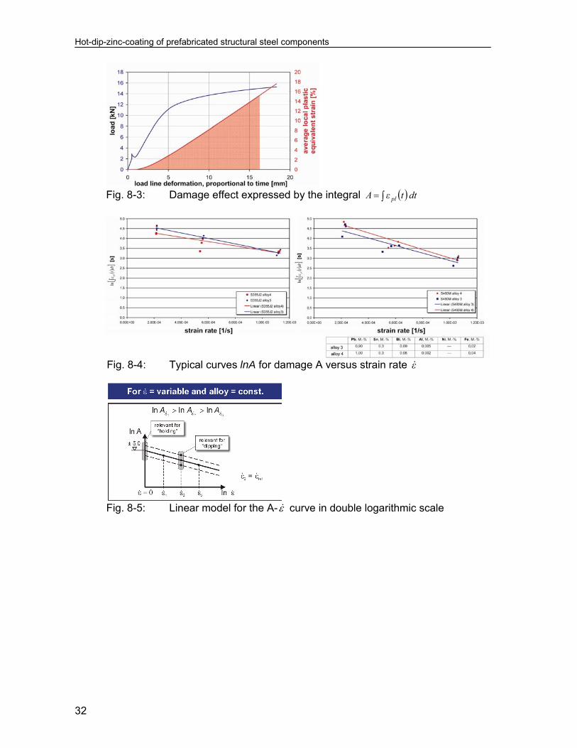
(3) The damaging effect of the alloy is expressed by the integral dttεA pl (area
under the pl(t)-curve) see fig. 8-3. Fig. 8-4 shows typical curves for the dependency of strain rate, where the integral A is plotted in the logarithmic scale ln A.
Fig. 8-2: Dependence of the LNT-test results on the variation of zinc alloy
and variation of the strain rate as used for tests
Hot-dip-zinc-coating of prefabricated structural steel components
32
Fig. 8-3: Damage effect expressed by the integral dttεA pl
Fig. 8-4: Typical curves lnA for damage A versus strain rate ε
Fig. 8-5: Linear model for the A- curve in double logarithmic scale

Hot-dip-zinc-coating of prefabricated structural steel components
33
Fig. 8-6: Correlation related to (4) The conclusion from the tests can be taken from fig. 8-5, where a linear model in
the double logarithmic scale for A and is given and typical strain rates for “dipping” ( ref2 εε for the relevant strain capacities ref in fig. 7-6) and for “holding”
0ε are indicated. As fig. 8-3 and fig. 8-4 show, a decrease of the strain rate from test to test while leaving the composition of the zinc alloy constant leads to lower strain resistances.
(5) In using the basic equation in fig. 8-6, where the related value
dt
ε
tεlnAn
*ref
R (8.1)
versus the strain rate s
1ε is plotted and the typical “dipping” situation can be
expressed by the pair 4
ref,R 105ε and 5,2An (8.2)
and the “holding” situation by the pair 0εR and 0,5An , (8.3)
the following conclusion can be drawn for the holding time tS
SR tε
0
5*
ref,R
eε
dttε. (8.4)
With using a linear function for the (t) curve, see fig. 8-6:
Hot-dip-zinc-coating of prefabricated structural steel components
34
S
tε
0*
ref,R
SR*
ref,R
tε
tε5,0dt
ε
tεSR
(8.5)
the holding time reads
SR
*ref,R
SR
*ref,R
S tε
ε5s
tε
ε148.2t [min] (8.6)
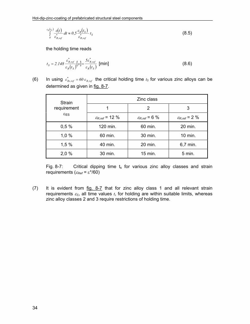
(6) In using ref,R
*ref,Rs ε60ε the critical holding time tS for various zinc alloys can be
determined as given in fig. 8-7.
Strain requirement
ES
Zinc class
1 2 3
R,ref = 12 % R,ref = 6 % R,ref = 2 %
0,5 % 120 min. 60 min. 20 min.
1,0 % 60 min. 30 min. 10 min.
1,5 % 40 min. 20 min. 6,7 min.
2,0 % 30 min. 15 min. 5 min.
Fig. 8-7: Critical dipping time ts for various zinc alloy classes and strain requirements (Ref = */60)
(7) It is evident from fig. 8-7 that for zinc alloy class 1 and all relevant strain
requirements Es all time values ts for holding are within suitable limits, whereas zinc alloy classes 2 and 3 require restrictions of holding time.
Hot-dip-zinc-coating of prefabricated structural steel components
35
9 Stress-strain requirements 9.1 General (1) Equivalent plastic strain requirements result from an accumulation of strains due
to: 1. time history of fabrication,
2. time history of heating process during dipping if the instationary heating process is relevant for cracking,
3. time history of the exposure in the zinc bath, if the time effect on the reduction of strain capacity (holding time) is relevant for cracking.
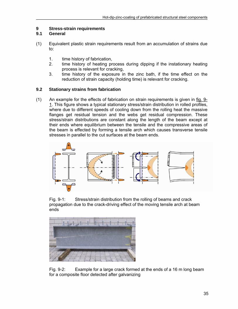
9.2 Stationary strains from fabrication (1) An example for the effects of fabrication on strain requirements is given in fig. 9-
1. This figure shows a typical stationary stress/strain distribution in rolled profiles, where due to different speeds of cooling down from the rolling heat the massive flanges get residual tension and the webs get residual compression. These stress/strain distributions are constant along the length of the beam except at their ends where equilibrium between the tensile and the compressive areas of the beam is effected by forming a tensile arch which causes transverse tensile stresses in parallel to the cut surfaces at the beam ends.
Fig. 9-1: Stress/strain distribution from the rolling of beams and crack
propagation due to the crack-driving effect of the moving tensile arch at beam ends
Fig. 9-2: Example for a large crack formed at the ends of a 16 m long beam
for a composite floor detected after galvanizing
Hot-dip-zinc-coating of prefabricated structural steel components
36
(2) If at this surface strain concentrations are present due to welding and shape effects and additional plastic strains form due to the temperature gradient from dipping into the zinc bath a liquid metal assisted macro crack may occur that propagates to a large size due to the crack-driving effect of the accompanying tensile arch, see fig. 9-2.
(3) A particular hazard results from cold forming of prefabricated structural
components, e.g. for hooks, loops etc., where liquid metal assisted cracking starts at the concave side of the imposed curvature.
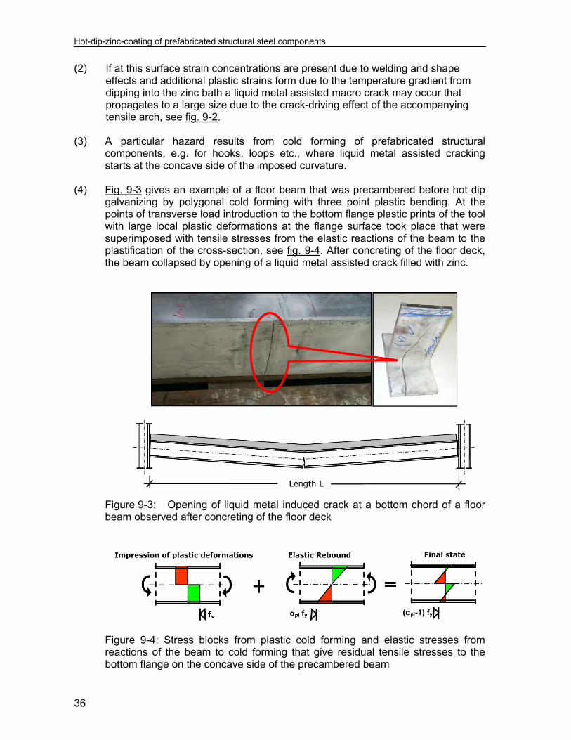
(4) Fig. 9-3 gives an example of a floor beam that was precambered before hot dip
galvanizing by polygonal cold forming with three point plastic bending. At the points of transverse load introduction to the bottom flange plastic prints of the tool with large local plastic deformations at the flange surface took place that were superimposed with tensile stresses from the elastic reactions of the beam to the plastification of the cross-section, see fig. 9-4. After concreting of the floor deck, the beam collapsed by opening of a liquid metal assisted crack filled with zinc.
Figure 9-3: Opening of liquid metal induced crack at a bottom chord of a floor beam observed after concreting of the floor deck
Figure 9-4: Stress blocks from plastic cold forming and elastic stresses from reactions of the beam to cold forming that give residual tensile stresses to the bottom flange on the concave side of the precambered beam

Hot-dip-zinc-coating of prefabricated structural steel components
37
9.3 Instationary strains from dipping
Fig. 9-5: Time history of dipping for a mass particle of the structural
component (1) Fig. 9-5 shows the dipping procedure versus time and fig. 9-6 gives an example
of the temperature distributions over a selected cross-section resulting in residual strain distributions that are laid over the residual strain distributions of the steel component from fabrication.
(2) The residual strains that arise from the temperature distribution are shown in fig.
9-7.
Fig. 9-6: Time history of temperature for a cross-section of a structural component
Fig. 9-7: Residual strain increments from temperature distributions

Hot-dip-zinc-coating of prefabricated structural steel components
38
9.4 Superposition of stationary and instationary strains
Fig. 9-8: Example of a time history of equivalent plastic strain requirements (1) Fig. 9-8 gives the principle of the time history of equivalent plastic strain from
fabrication (t=0), superimposed with strains from the heating with the time variant temperature distributions until full heating is achieved (situation without any temperature gradient). The full equivalent plastic strain accumulation process including stress relief by the exposure to the zinc bath is relevant for the strain requirement at a certain time.
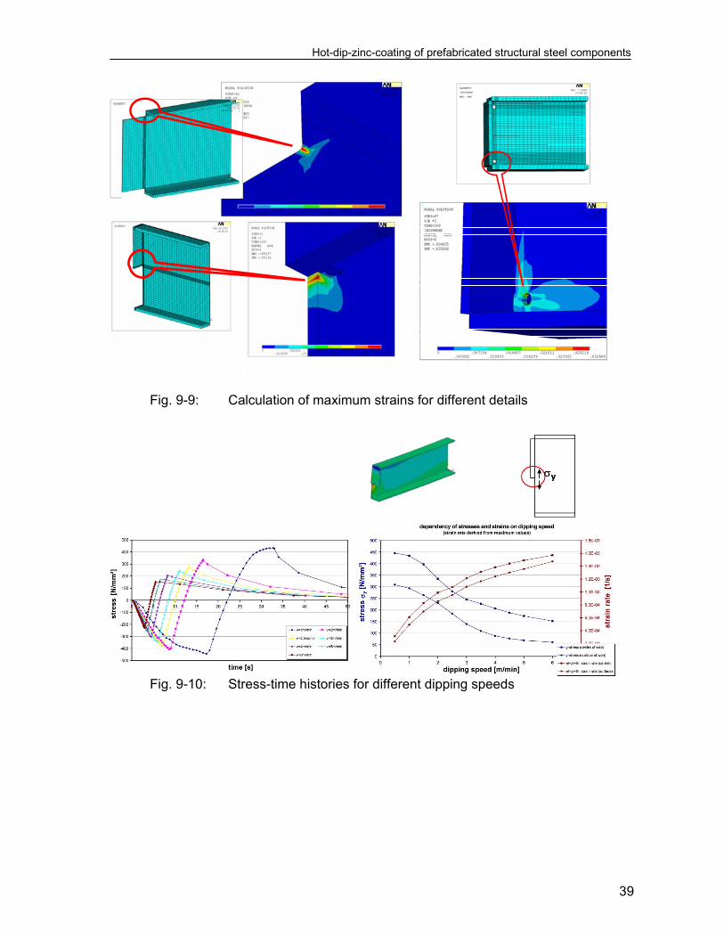
9.5 Conclusions from variation of detail and plate thickness (1) FEM-calculations of the instationary component of the strain history have been
performed with variation of:
- the structural detail considered, see fig. 9-9, - the immersion speed during dipping into the smelter, see fig. 9-10, - the alloy with varying heat transition coefficients, see fig. 9-11.
Hot-dip-zinc-coating of prefabricated structural steel components
39
Fig. 9-9: Calculation of maximum strains for different details
Fig. 9-10: Stress-time histories for different dipping speeds

Hot-dip-zinc-coating of prefabricated structural steel components
40
Fig. 9-11: Effect of different zinc-alloys with different heat-transition
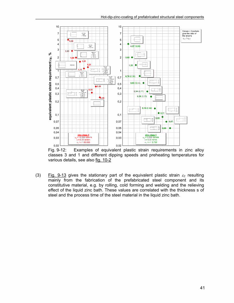
coefficients at on temperature- and equivalent strain-histories (2) Fig. 9-12 gives examples for the instationary part of the equivalent plastic strain
requirements E for two alloys and immersion speeds representing the normal conditions before and after actions were undertaken to reduce damages [75]:
Before actions: zinc alloy class 3 with the parameters:
v = 0,25 m/min (immersion speed) t = 15.000 W/m2K (heat transfer coefficient) TV = 50°C (preheating temperature) TBath = 450°C
After actions: zinc alloy class 1 with the parameters:
v = 0,80 m/min t = 3.000 W/m2K TV = 20°C TBath = 450°C
The data apply for various details and steel grade S355J2. They show for the details that are comparable, that zinc alloy 1 in connection with higher dipping speeds gives smaller strain requirements.
Hot-dip-zinc-coating of prefabricated structural steel components
41
Fig. 9-12: Examples of equivalent plastic strain requirements in zinc alloy
classes 3 and 1 and different dipping speeds and preheating temperatures for various details, see also fig. 10-2
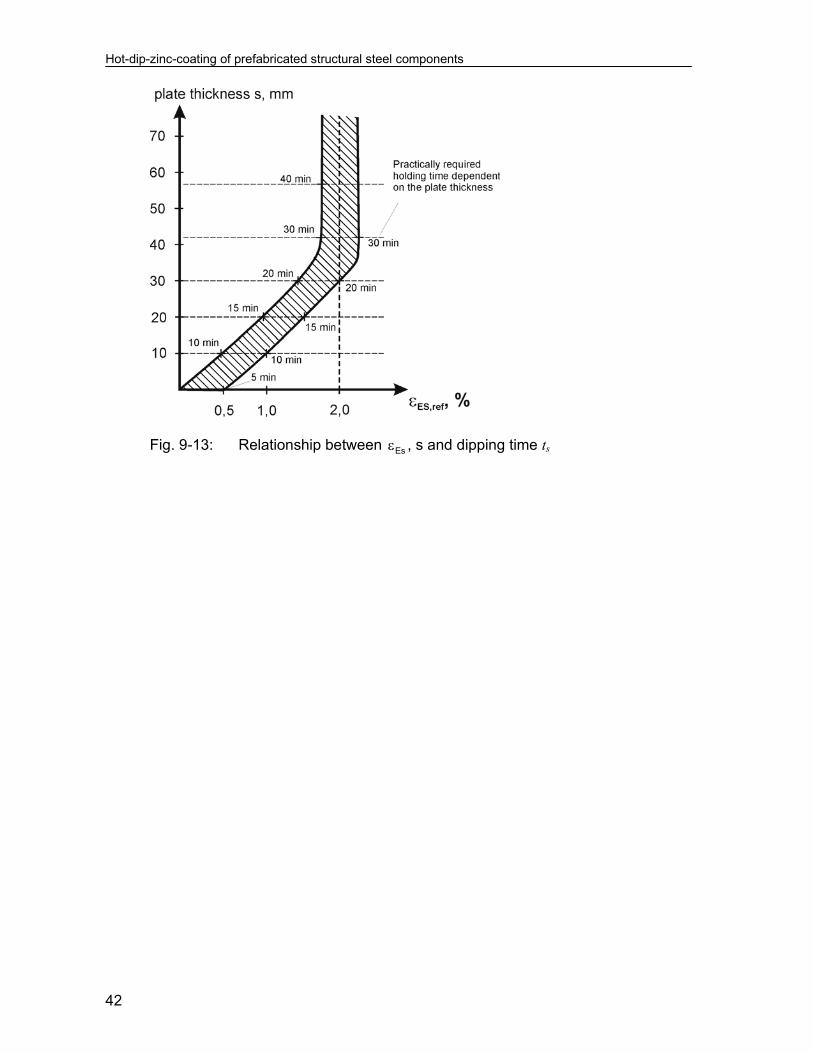
(3) Fig. 9-13 gives the stationary part of the equivalent plastic strain E resulting
mainly from the fabrication of the prefabricated steel component and its constitutive material, e.g. by rolling, cold forming and welding and the relieving effect of the liquid zinc bath. These values are correlated with the thickness s of steel and the process time of the steel material in the liquid zinc bath.
Hot-dip-zinc-coating of prefabricated structural steel components
42
Fig. 9-13: Relationship between Es , s and dipping time ts

Hot-dip-zinc-coating of prefabricated structural steel components
43
10 Limit state assessments based on equivalent plastic strains (1) The mechanical background of the two design situations used for the limit state
assessments to avoid cracking in the zinc bath is given in fig. 10-1.
Fig. 10-1: Cases a) and b) for the limit state assessment (2) This figure demonstrates the principle of the limit state assessment for two zinc
alloys with different aggressiveness:
case a: For a highly aggressive zinc alloy (e.g. zinc class 3) the peak value of the time history of strain-requirements reached during the dipping process is relevant for cracking. Cracks may occur during the submerging of the structural component into the zinc bath and appropriate measures to reduce the risk are related to reducing the peak value by preheating or reducing the time required for full submergence.
case b: For moderate and low aggressive zinc alloys (e.g. zinc class 1), the
exposure time in the zinc bath leading to a reduction of strain resistance is relevant for cracking, and appropriate measures to reduce the risk are related to reducing the exposure time by reducing the thickness of plates and the differences in thickness of plates.
(3) For case a) design situation during the dipping phase-, fig. 10-2 gives the results
of the ratios
R
E
ε
εη (10.1)
for the typical conditions before and after actions to reduce damages [75]

Hot-dip-zinc-coating of prefabricated structural steel components
44
Fig. 10-2: Comparison of equivalent plastic strain requirements E and plastic strain resistance R in zinc alloy classes 3 and 1 and different dipping speeds and preheating temperatures for various details, see also fig. 9-12
Apparently the content of tin has a dominant effect and zinc alloy class 3 should
not be used for many details that are frequently applied in practice, whereas zinc alloy class 1 is applicable for all details investigated.
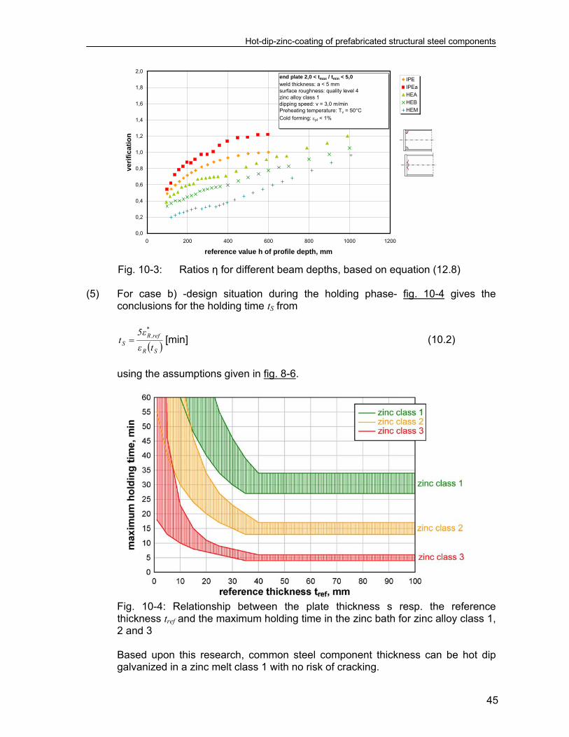
(4) Fig. 10-3 gives a further detail for the determination of for beams with end
plates and cut outs, which identifies the effect of the depth of beams as observed by damages.
Hot-dip-zinc-coating of prefabricated structural steel components
45
0,0
0,2
0,4
0,6
0,8
1,0
1,2
1,4
1,6
1,8
2,0
0 200 400 600 800 1000 1200
reference value h of profile depth, mm
ve
rifi
ca
tio
n
IPE
IPEa
HEA
HEB
HEM
end plate 2,0 < tmax / tmin < 5,0 weld thickness: a < 5 mmsurface roughness: quality level 4zinc alloy class 1dipping speed: v = 3,0 m/minPreheating temperature: Tv = 50°C
Cold forming: pl < 1%
Fig. 10-3: Ratios η for different beam depths, based on equation (12.8) (5) For case b) -design situation during the holding phase- fig. 10-4 gives the
conclusions for the holding time tS from
SR
*ref,R
S tε
ε5t [min] (10.2)
using the assumptions given in fig. 8-6.
Fig. 10-4: Relationship between the plate thickness s resp. the reference thickness tref and the maximum holding time in the zinc bath for zinc alloy class 1, 2 and 3
Based upon this research, common steel component thickness can be hot dip
galvanized in a zinc melt class 1 with no risk of cracking.


Hot-dip-zinc-coating of prefabricated structural steel components
47
11 Validation of the strain-oriented assessment method 11.1 General (1) In the following examples for cracks observed after galvanizing or after erection
of hot-dip galvanized components are given, which look plausible if compared with the assessment method based on equation (10.1) and (10.2).
(2) Apparently the type of zinc alloy is a main parameter; zinc alloys according to
zinc class 1 would reduce the problems to mainly structural aspects as choice of steel, cross-section and structural detailing in connection with procedural aspects as dipping speed and holding time.
(3) The following examples also give an impression how cracks starting at typical
crack initiation points look like. 11.2 Structural components from car-parkings
Construction: IPE550, l ~ 16 m Detail: half endplate t = 12,5 mm Material: S460N, large KV-value in web Zinc alloy: 0,8 Pb + 1,1 Sn + 0,07 Bi Crack: starting from end of endplate, l = 1800 mm
Construction: IPE450, l ~ 16 m, tEndplate = 12,5 mm Detail: half endplate wit cut out d = 30 mm Material: S460N Zinc alloy: 1,0 Pb + 1,1 Sn + 0,08 Bi
(alloy composition does not comply with EN ISO 1461) Crack: starting from cut out, l = 200 mm
Hot-dip-zinc-coating of prefabricated structural steel components
48
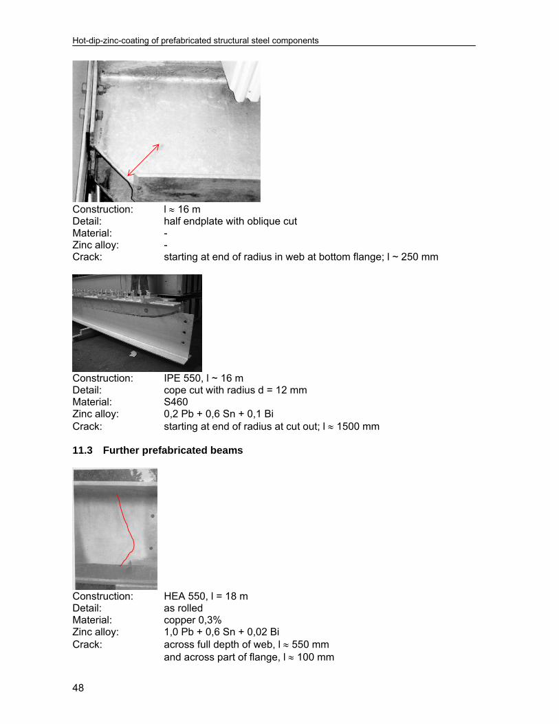
Construction: l 16 m Detail: half endplate with oblique cut Material: - Zinc alloy: - Crack: starting at end of radius in web at bottom flange; l ~ 250 mm
Construction: IPE 550, l ~ 16 m Detail: cope cut with radius d = 12 mm Material: S460 Zinc alloy: 0,2 Pb + 0,6 Sn + 0,1 Bi Crack: starting at end of radius at cut out; l 1500 mm 11.3 Further prefabricated beams
Construction: HEA 550, l = 18 m Detail: as rolled Material: copper 0,3% Zinc alloy: 1,0 Pb + 0,6 Sn + 0,02 Bi Crack: across full depth of web, l 550 mm and across part of flange, l 100 mm

Hot-dip-zinc-coating of prefabricated structural steel components
49
Construction: HEB 1000, l = 18 m Detail: holes, d = 36 mm Material: - Zinc alloy: 0,9 Pb + 0,8 Sn + 0,02 Bi Crack: starting at holes, l 250 mm
Construction: HD 400 x 509, main tension chord of a lattice girder
in a stadium roof Detail: plate inserted in web, tpl = 80 mm Material: S355 J2 G3 Zinc alloy: 1,0 Pb + 1,1 Sn + 0,04 Bi (alloy composition does not comply with EN ISO 1461) Crack: crescent-like crack at the end of inserted plate through entire web and parts of top and bottom flange, l ~ 400 mm 11.4 Prefabricated columns
Construction: HEB 340 Detail: horizontal and vertical attachments, tpl = 30 mm and tpl = 50 mm with holes and cut outs Material: S355 J2 G3 Zinc alloy: 0,3 Pb + 0,9 Sn + 0,08 Bi Crack: starting at holes and cut outs, l ~ 50 mm; at welds l ~ 30 mm
Hot-dip-zinc-coating of prefabricated structural steel components
50
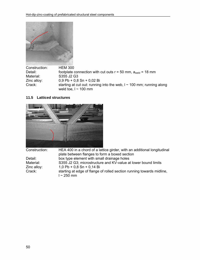
Construction: HEM 300 Detail: footplate connection with cut outs r = 50 mm, aweld = 18 mm Material: S355 J2 G3 Zinc alloy: 0,9 Pb + 0,8 Sn + 0,02 Bi Crack: starting at cut out: running into the web, l ~ 100 mm; running along
weld toe, l ~ 100 mm 11.5 Latticed structures
Construction: HEA 400 in a chord of a lattice girder, with an additional longitudinal
plate between flanges to form a boxed section Detail: box type element with small drainage holes Material: S355 J2 G3; microstructure and KV-value at lower bound limits Zinc alloy: 1,0 Pb + 0,8 Sn + 0,14 Bi Crack: starting at edge of flange of rolled section running towards midline,
l ~ 250 mm

Hot-dip-zinc-coating of prefabricated structural steel components
51
Construction: HEA 400 Detail: transverse stiffener Material: S355 J2 G3; microstructure and KV-value at lower bound limits Zinc alloy: 1,0 Pb + 0,8 Sn + 0,14 Bi Crack: starting at flange edge, l ~ 150 mm
Construction: welded built-up connection element Detail: lamellas inserted into gusset plate Material: S355 J2 G3 Zinc alloy: 1,0 Pb + 0,9 Sn + 0,02 Bi Crack: starting at weld-around, l ~ 60 mm 11.6 Cold-formed components
Construction: IPE 450, l 16 m; Precambered by cold forming Detail: local imprint in flange surface from tool for 3-point plastic bending Material: S460 N Zinc alloy: 1,0 Pb + 1,1 Sn + 0,08 Bi Crack: transverse to the flange, l 200 mm

Hot-dip-zinc-coating of prefabricated structural steel components
52
11.7 Hollow section components
Construction: welded box girder, t = 8 mm; aweld = 5 mm Detail: longitudinal fillet welds Material: S355 J2 G3 Zinc alloy: 0,7 Pb + 0,2 Sn Crack: starting at edge, l ~ 70 mm
Construction: circular hollow section, RO273 x 6,3, acting as tension rod for a
stadium roof (suspension) Detail: inserted gusset plate Material: S355 Zinc alloy: 0,9 Pb + 0,8 Sn + 0,01 Bi Crack: starting at end of gusset plate, l 20-100 mm

Hot-dip-zinc-coating of prefabricated structural steel components
53
12 Transfer of results based on equivalent plastic strains into engineering models for practical assessments
(1) The limit state assessment based on equivalent plastic strain may be used as
background procedure for developing more easy-to-use rules for practical application.
(2) Such easy-to-use rules may be based on assessment formulae applicable both
for case a) – the dipping process – and case b) – the holding phase -, see fig. 12-1. The formulae are derived in section 13, where it is shown, that the results are equivalent to the results of an assessment with equivalent plastic strains.
Fig. 12-1: Flow chart for the structural assessment to avoid cracking from liquid metal embrittlement
(3) A further step of simplification is an assessment procedure based on technical
classes, that avoids any numerical verification. This procedure is given in section 15.
(4) Both the simplified assessment method in section 13 and the classification
method in section 15 apply to certain conditions for:
- design of the prefabricated structural steel components, - the semifinished (constituent) products, - the structural detailing and fabrication of steel components, - the preparation of steel components prior to the hot-dip-zinc-coating, - requirements for the zinc bath, - testing of the zinc bath,
which are addressed in section 14 of this report.

Hot-dip-zinc-coating of prefabricated structural steel components
54
(5) All the practical assessment procedures are calibrated to laboratory tests, numerical simulations and experiences. They use technical classes so that deliveries with crack sizes that may infringe the structural safety are excluded. Due to the large scatter of results a quantification of the reliability index for achieving freedom of relevant cracks is however not yet possible. Therefore confidence zones as specified in section 14 are introduced.

Hot-dip-zinc-coating of prefabricated structural steel components
55
13 Simplified engineering models for numerical assessment (1) In order to obtain a simple engineering model for assessing the dipping process,
a rectangular plate with the plate thickness s and the depth h is assumed to be dipped with the velocity v into the liquid zinc bath. The plate is supposed to be without residual stresses or strains, see fig. 13-1.
Fig. 13-1: Reference model for the dipping process (2) This reference model is used for the following purposes:
1. to calculate the time tt of a particular plate-element, see fig. 13-1, to heat up from the preheating temperature TV to the melting temperature of pure zinc Ta = 419°C,
In this calculation, the heat conductivity through the plate thickness is neglected. The heat transfer coefficient t is taken as the actual effective value for the zinc alloy in question,
2. to determine the time history of instationary residual stresses and strains
caused by strains * from temperature differences from dipping with different velocities v to identify the time t when the maximum of residual stresses and strains occurs,
3. to use the pseudo-limit state criterion based on the assumption that in the
beginning of the heating up phase the zinc coat freezes at the “cold” surface of the steel component and hence reduces the corrosion effect of the zinc alloy until the steel component has adopted the temperature of the zinc bath (cracking of the frozen zinc layer is not considered).
Based on this assumption, the limit state is defined by the requirement, that the time interval t for attaining the maximum of the time history of residual stresses should be smaller than the heating up time tt:
t - tt ≤ 0 (13.1) or
1tt
t
(13.2)

Hot-dip-zinc-coating of prefabricated structural steel components
56
4. to link the simplified limit state equation (13.2) to the actual limit state for equivalent plastic strains as given in fig. 10-1 case a) by adaption factors kc, see (8).
(3) The calculation of the reference time tt in fig. 13-1 is based on the following
assumptions: 1. The heat transfer between the zinc bath and the steel plate is constant
with time:
TTAαdt
dTVρC at (13.3)
where C is the specific heat capacity of the plate is the specific mass V is the volume of the plate T is the temperature of the plate t is the time t is the effective heat transfer coefficient for the zinc alloy A is the surface of the plate Ta is the melting temperature of pure zinc (419°C) TBath is the temperature of the zinc bath. 2. The first zinc coat freezes on the plate surface and prohibits further access
of aggressive constituents of the zinc alloy to the steel surface, thus protecting the steel from cracking. Any cracking of the frozen zinc coat is not considered.
(4) Equation (13.3) leads to:
TT
dT
A
CVdt
at
(13.4)
which gives
Bath
BathV
t
T
T att TC
TTn
sC
TT
dTsCt
a
V
41922
(13.5)
(5) For the example of a plate with s = 0,01 m TBath = 450°C TV = 50°C t = 6000 W/m2K C = 600 J/kg K = 7.800 kg/m3
Hot-dip-zinc-coating of prefabricated structural steel components
57
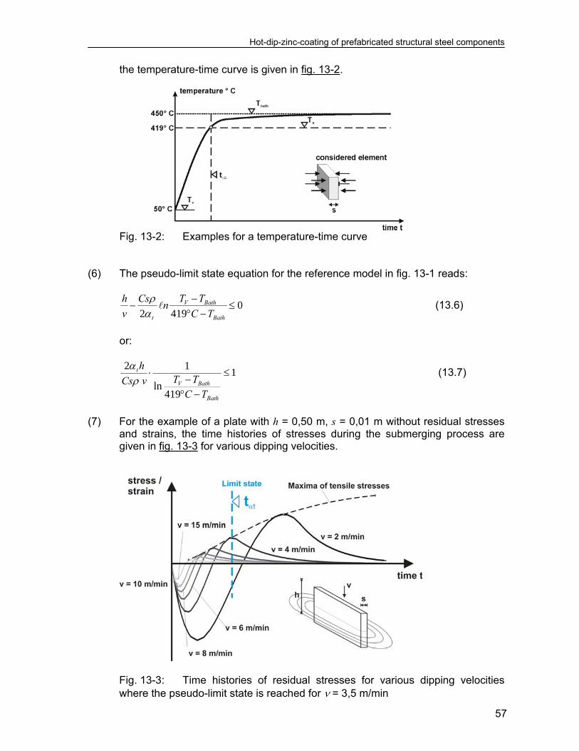
the temperature-time curve is given in fig. 13-2.
Fig. 13-2: Examples for a temperature-time curve (6) The pseudo-limit state equation for the reference model in fig. 13-1 reads:
04192
Bath
BathV
t TC
TTn
Cs
v
h
(13.6)
or:
1
419ln
12
Bath
BathV
t
TCTTvCs
h
(13.7)
(7) For the example of a plate with h = 0,50 m, s = 0,01 m without residual stresses
and strains, the time histories of stresses during the submerging process are given in fig. 13-3 for various dipping velocities.
Fig. 13-3: Time histories of residual stresses for various dipping velocities where the pseudo-limit state is reached for = 3,5 m/min

Hot-dip-zinc-coating of prefabricated structural steel components
58
In this figure the pseudo-limit state is reached for a velocity v = 3,5/min. (8) The link of the limit state of this model to the limit state of the model based on
strain assessment is given in fig. 13-4, where on the left side the limit state
condition 1tt
t
is given for the engineering model and on the right side the role
of the adaption factor kc is shown to adjust the value tt of the engineering model to the value
c
tt k
tt * (13.8)
consistent with the assessment model for strains.
Fig. 13-4: Conditions for the attainment of the pseudo-limit state (9) In conclusion, the basic formula for verifying freedom of cracks from hot-dip-
galvanizing is
2 1
419
tc
v Bath
Bath
hk
T TC s v lnC T
(13.9)
where is the utilisation rate, that theoretically should not exceed the value
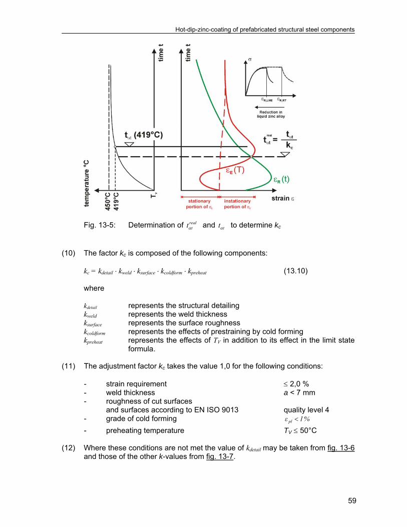
0,1 , see figure 13-4. (10) Fig. 13-5 gives more details to determine the adaption value kc from equation
(13.8):
1
419ln
12
bath
bathv
tc
tc
T
TTvsC
hk
t
tk
1
419ln
12
bath
bathv
t
t
T
TTvsC
h
t
t
engineering model verification model
Hot-dip-zinc-coating of prefabricated structural steel components
59
Fig. 13-5: Determination of real
tt and tt to determine kc
(10) The factor kc is composed of the following components: kc = kdetail kweld ksurface kcoldform kpreheat (13.10) where kdetail represents the structural detailing kweld represents the weld thickness ksurface represents the surface roughness kcoldform represents the effects of prestraining by cold forming
kpreheat represents the effects of TV in addition to its effect in the limit state formula.
(11) The adjustment factor kc takes the value 1,0 for the following conditions: - strain requirement 2,0 % - weld thickness a < 7 mm - roughness of cut surfaces
and surfaces according to EN ISO 9013 quality level 4 - grade of cold forming %1ε pl
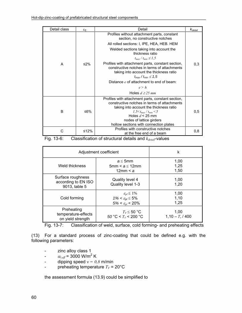
- preheating temperature TV 50°C (12) Where these conditions are not met the value of kdetail may be taken from fig. 13-6
and those of the other k-values from fig. 13-7.
Hot-dip-zinc-coating of prefabricated structural steel components
60
Detail class E Detail kdetail
A ≤2%
Profiles without attachment parts, constant section, no constructive notches
All rolled sections: I, IPE, HEA, HEB. HEM
Welded sections taking into account the thickness ratio tmax / tmin 1,5
Profiles with attachment parts, constant section, constructive notches in terms of attachments
taking into account the thickness ratio tmax / tmin 1,5
Distance e of attachment to end of beam:
e > h
Holes d 25 mm
0,3
B ≤6%
Profiles with attachment parts, constant section, constructive notches in terms of attachments
taking into account the thickness ratio 1,5<tmax / tmin <5
Holes d < 25 mm nodes of lattice girders
hollow sections with connection plates
0,5
C ≤12% Profiles with constructive notches
at the free end of a beam 0,8
Fig. 13-6: Classification of structural details and kdetail-values
Adjustment coefficient k
Weld thickness a 5mm
5mm < a 12mm 12mm < a
1,00 1,25 1,50
Surface roughness according to EN ISO
9013, table 5
Quality level 4 Quality level 1-3
1,00 1,20
Cold forming pl 1% 1% < pl 5%
5% < pl < 20%
1,00 1,10 1,25
Preheating temperature-effects
on yield strength
TV 50 °C 50 °C < TV < 200 °C
1,00 1,10 – Tv / 400
Fig. 13-7: Classification of weld, surface, cold forming- and preheating effects (13) For a standard process of zinc-coating that could be defined e.g. with the following parameters:
- zinc alloy class 1 - t,eff = 3000 W/m2 K - dipping speed = 0,8 m/min - preheating temperature TV = 20°C
the assessment formula (13.9) could be simplified to

Hot-dip-zinc-coating of prefabricated structural steel components
61
27
1
s
hkC (13.11)
(14) For the verification of the holding time via formula (10.2) and for the zinc alloy
class 1 see (13) the permissible holding time dependant on the plate thickness may be taken from fig. 13-8.
Fig. 13-8: Maximum holding time in the zinc bath for zinc alloy class 1 (see
(13)) (15) For plate thickness tref 30 mm the usual holding time is smaller than 30 min, so
that no extra provisions apply. For tref > 30 mm the limitation of the holding time to 27 min (without further procedure tests) should be observed.


Hot-dip-zinc-coating of prefabricated structural steel components
63
14 Introduction of Confidence zones (1) The limit state conditions in equation (10.2) and (13.9) are based on assumptions
for the classification of thicknesses and details as well as for constituent products and for fabrications as follows:
1. Constituent steel products are free of “crack like defects” on the surface
according to EN 10163-Part 2 for plates and EN 10163-Part 3, Class C subgroup 1 for long products.
In particular long products with large depths are produced such that residual stresses and differences of yield strength and impact energy across the cross-section are kept small. The chemical composition of steels in particular those produced on the scrab-route should be controlled, and meet the requirements for good weldability.
2. Residual strains caused by fabrication are limited by appropriate detailing,
weld preparation, welding procedures and welding sequences e.g.:
- welding of butt welds before fillet welds, - no intermitted welds, - flexible assembly, - accurate and sufficiently robust tackling, - no exceedance of weld thicknesses required by design.
3. At welds a component has preferably almost equal plate thicknesses;
where the ratio of plate thicknesses exceeds 5min
max
t
t, the component
should be separated by assembly joints.
4. The superposition of residual strains from thermal cutting at edges and from welding is avoided by a minimum excess length for fillet welds of 2a + 3 mm where a is the weld thickness. The same value applies for the minimum distance of edges of holes to welds.
5. Critical micro-cracks from thermal cutting and punching are avoided by:
- considering either a maximum surface hardness of 340 HV
according to EN ISO 14713 and fabrication of punched holes with undersize and reaming to normal size as for structures subjected to fatigue loads,
- or fabrication of punched holes or cold-cut edges according to
requirements of procedure tests.
6. Excessive cold-forming effects are excluded by:
Hot-dip-zinc-coating of prefabricated structural steel components
64
- considering either the strain limits tr
tplast
2
2 %
where t is the plate thickness, r is the inner radius of cold forming
or annealing in cold formed areas,
- application of appropriate “notch-free” tools for cold forming,
- no punch marking except at locations where cracking is not expected to occur (e.g. at end plates).
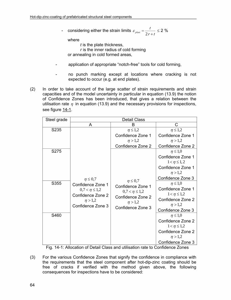
(2) In order to take account of the large scatter of strain requirements and strain
capacities and of the model uncertainty in particular in equation (13.9) the notion of Confidence Zones has been introduced, that gives a relation between the utilisation rate in equation (13.9) and the necessary provisions for inspections, see figure 14-1.
Steel grade Detail Class
A B C S235
7,0 Confidence Zone 1
2,17,0 Confidence Zone 2
2,1 Confidence Zone 3
2,1 Confidence Zone 1
2,1 Confidence Zone 2
2,1 Confidence Zone 1
2,1 Confidence Zone 2
S275
7,0 Confidence Zone 1
2,17,0 Confidence Zone 2
2,1 Confidence Zone 3
0,1 Confidence Zone 1
1 1, 2 Confidence Zone 1
2,1 Confidence Zone 3
S355 0,1 Confidence Zone 1
2,11 Confidence Zone 2
2,1 Confidence Zone 3
S460 0,1 Confidence Zone 2
2,11 Confidence Zone 2
2,1 Confidence Zone 3
Fig. 14-1: Allocation of Detail Class and utilisation rate to Confidence Zones (3) For the various Confidence Zones that signify the confidence in compliance with
the requirements that the steel component after hot-dip-zinc coating should be free of cracks if verified with the method given above, the following consequences for inspections have to be considered:

Hot-dip-zinc-coating of prefabricated structural steel components
65
- for Confidence Zone 1 only visual inspections (100 %) are necessary,
- for Confidence Zone 2 in addition to the visual inspections spot checks using a modified MT-method with adequate sensitivity should be agreed (minimum 1 detail from the relevant detail class per lot) to prove that the full assessment procedure has been safe-sided,
- for Confidence Zone 3 in addition to the visual inspection a systematic
check of steel components should be agreed (minimum 1 detail from each type of detail occurring in Detail Class C per lot) to prove that the full assessment procedure has been safe-sided.
(4) For complex prefabricated structural components as given in fig. 14-2, the
classification may be performed considering the “component method” used in connection design, see EN 1993-1-8. The class with the most onerous detail should be considered as representative for the complete steel component.
Fig. 14-2: Example for the application of the “component-method” for structural connections to the classification of complex prefabricated steel components (5) In order to control the thermal expansion of lattice girders and similar built-up
structures it is recommended to avoid excessive instationary residual strains due to thermal gradients in the dipping process by segmentation into components with assembly joints.
h
L
tref
end plate
end plate
attachment
transverse stiffeners


Hot-dip-zinc-coating of prefabricated structural steel components
67
15 Classification system without numerical assessment (1) In the following a classification system is derived from the assessment methods
in section 13 and section 14 that applies to standard conditions for - the zinc alloy: zinc alloy class 1, see fig. 7-7, - dipping speed: 0,8 m/min, - the preheating temperature: TV = 15°C – 20°C, and to frequently used - types of construction, - types of detail, - plate thicknesses, assuming ways of fabrication that keep strain-requirements small. (2) The classification system, that does not need any numerical assessment
comprises: 1. classification of construction type, 2. classification of structural detail, 3. classification of predominant product thickness see fig. 15-1.

Hot-dip-zinc-coating of prefabricated structural steel components
68
Fig. 15-1: Classification of structural components into Construction Classes,
Detail Classes and Thickness Classes (3) Fig. 15-2 gives the classification of prefabricated steel components to
Construction Classes with a distinction of steel grade, toughness and beam depth.

Hot-dip-zinc-coating of prefabricated structural steel components
69
Legend:
class Ia: Profiles (all open sections, all hollow sections) class Ib: Profiles IPE and HE series and equivalent *) class Ic: Profiles IPE and HE series and equivalent *) class II: Profiles IPE and HEA series and equivalent *) class III: Profiles IPE and HEA series and equivalent *)
*) For built up welded profiles equivalent geometrical dimensions as for rolled sections apply. Note: The values h1 and h2 have been determined for profiles with large depths h and small web thickness s (h/s 40). The values h1 and h2 are safe-sided for any profile with about h/s < 40.
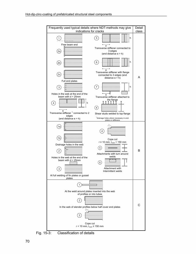
Fig. 15-2: Classification of prefabricated steel components to Construction Classes (4) Fig. 15-3 gives a classification of details, where the risk of occurrence of cracks
(due to the decrease of safety margin of strain assessment) is the greater the higher the class is (A C). Therefore, the Detail Classes are associated with different Confidence Zones.
(5) The classification of the predominant product thickness refers to the permissible
holding time ts in fig. 13-8. (6) Fig. 15-4 gives the consequences of combination of Construction Class, Detail
Class and Thickness Class for the Confidence Zone.
Hot-dip-zinc-coating of prefabricated structural steel components
70
Frequently used typical details where NDT-methods may give
indications for cracks Detail class
Free beam end
Full end plates
Holes in the web at the end of the
beam with d > 25mm
Transverse stiffener *) connected to 2
edges (end distance e > h)
Transverse stiffener connected to
3 edges (end distance e > h)
Transverse stiffener with flange
connected to 3 edges (end distance e > h)
Transverse stiffener attached to
the flange
Shear studs welded to top flange
*)drainage holes where necessary in end-plates or stiffeners
A
Drainage holes in the web
Holes in the web at the end of the
beam with d < 25mm
At full welding of fin plates or gusset
plates
Cope cut
r ≥ 10 mm, lcope < 150 mm
Attachments with turn around
welds
Attachment with
Intermittent welds
B
At the weld around plates inserted into the web
of profiles or into tubes
In the web of slender profiles below half cover end plates
Cope cut
r < 10 mm, lcope ≥ 150 mm
C
Fig. 15-3: Classification of details
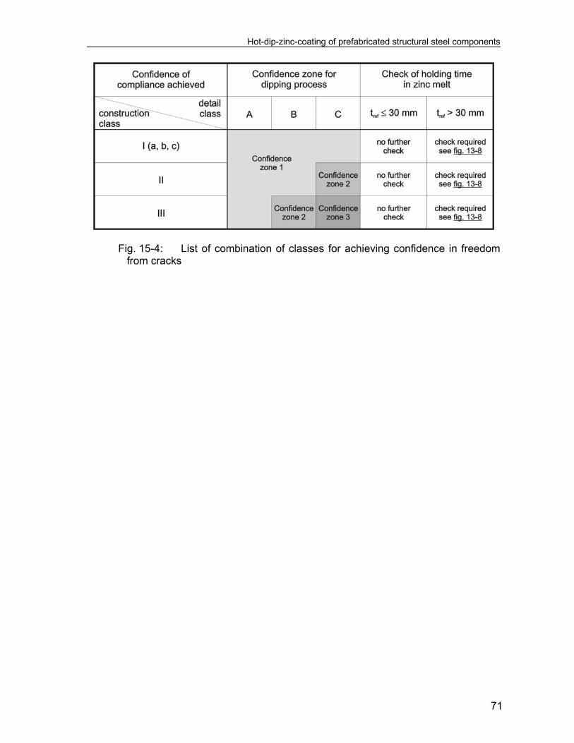
Hot-dip-zinc-coating of prefabricated structural steel components
71
Fig. 15-4: List of combination of classes for achieving confidence in freedom from cracks

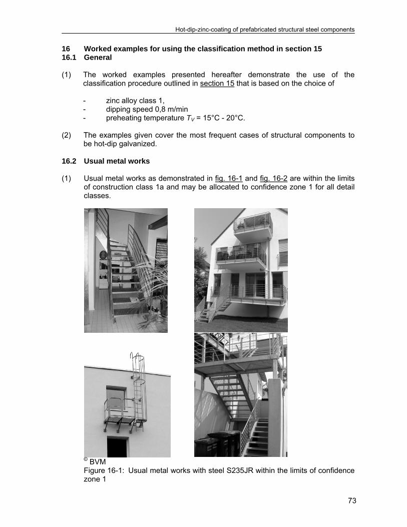
Hot-dip-zinc-coating of prefabricated structural steel components
73
16 Worked examples for using the classification method in section 15 16.1 General (1) The worked examples presented hereafter demonstrate the use of the
classification procedure outlined in section 15 that is based on the choice of - zinc alloy class 1, - dipping speed 0,8 m/min - preheating temperature TV = 15°C - 20°C. (2) The examples given cover the most frequent cases of structural components to
be hot-dip galvanized. 16.2 Usual metal works (1) Usual metal works as demonstrated in fig. 16-1 and fig. 16-2 are within the limits
of construction class 1a and may be allocated to confidence zone 1 for all detail classes.
© BVM
Figure 16-1: Usual metal works with steel S235JR within the limits of confidence zone 1
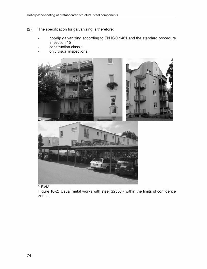
Hot-dip-zinc-coating of prefabricated structural steel components
74
(2) The specification for galvanizing is therefore:
- hot-dip galvanizing according to EN ISO 1461 and the standard procedure in section 15
- construction class 1 - only visual inspections.
© BVM Figure 16-2: Usual metal works with steel S235JR within the limits of confidence zone 1
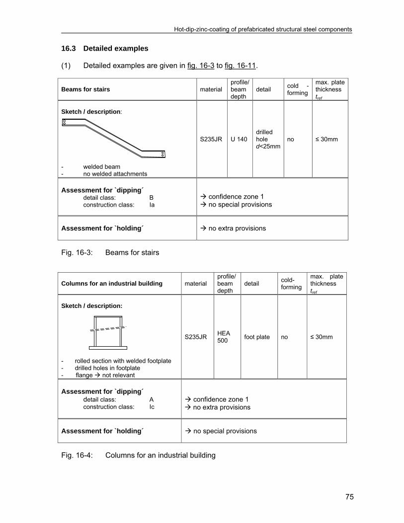
Hot-dip-zinc-coating of prefabricated structural steel components
75
16.3 Detailed examples (1) Detailed examples are given in fig. 16-3 to fig. 16-11. Beams for stairs material
profile/ beam depth
detail cold -forming
max. plate thickness tref
Sketch / description:
- welded beam - no welded attachments
S235JR U 140 drilled hole d<25mm
no ≤ 30mm
Assessment for `dipping´ detail class: B
construction class: Ia
confidence zone 1 no special provisions
Assessment for `holding´
no extra provisions
Fig. 16-3: Beams for stairs Columns for an industrial building material
profile/ beam depth
detail cold-forming
max. plate thickness tref
Sketch / description:
- rolled section with welded footplate - drilled holes in footplate - flange not relevant
S235JR HEA 500
foot plate no ≤ 30mm
Assessment for `dipping´ detail class: A
construction class: Ic
confidence zone 1 no extra provisions
Assessment for `holding´
no special provisions
Fig. 16-4: Columns for an industrial building
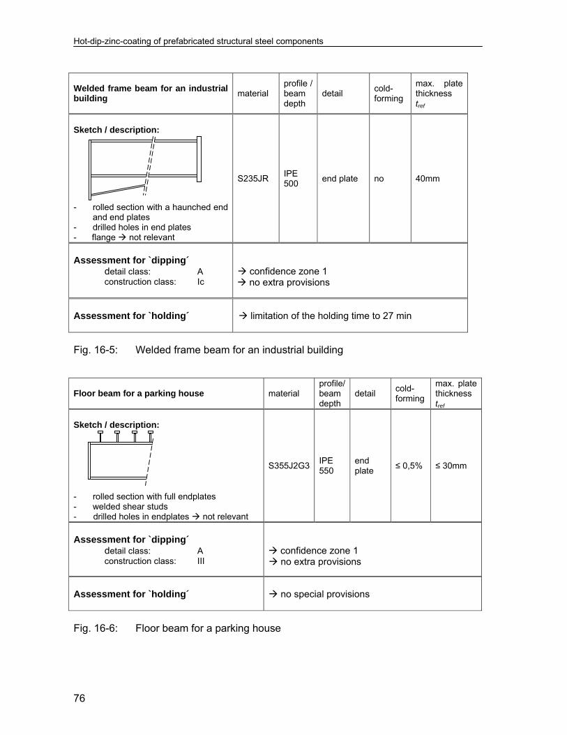
Hot-dip-zinc-coating of prefabricated structural steel components
76
Welded frame beam for an industrial building
material profile / beam depth
detail cold-forming
max. plate thickness tref
Sketch / description:
- rolled section with a haunched end
and end plates - drilled holes in end plates - flange not relevant
S235JR IPE 500
end plate no 40mm
Assessment for `dipping´ detail class: A
construction class: Ic
confidence zone 1 no extra provisions
Assessment for `holding´
limitation of the holding time to 27 min
Fig. 16-5: Welded frame beam for an industrial building Floor beam for a parking house material
profile/ beam depth
detail cold-forming
max. plate thickness tref
Sketch / description:
- rolled section with full endplates - welded shear studs - drilled holes in endplates not relevant
S355J2G3IPE 550
end plate
≤ 0,5% ≤ 30mm
Assessment for `dipping´ detail class: A
construction class: III
confidence zone 1 no extra provisions
Assessment for `holding´
no special provisions
Fig. 16-6: Floor beam for a parking house
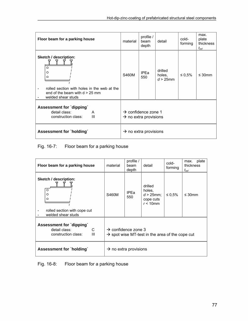
Hot-dip-zinc-coating of prefabricated structural steel components
77
Floor beam for a parking house
material profile / beam depth
detail cold-forming
max. plate thickness tref
Sketch / description:
- rolled section with holes in the web at the
end of the beam with d > 25 mm - welded shear studs
S460M IPEa 550
drilled holes, d > 25mm
≤ 0,5% ≤ 30mm
Assessment for `dipping´ detail class: A
construction class: III
confidence zone 1 no extra provisions
Assessment for `holding´
no extra provisions
Fig. 16-7: Floor beam for a parking house Floor beam for a parking house material
profile / beam depth
detail cold-forming
max. plate thickness tref
Sketch / description:
- rolled section with cope cut - welded shear studs
S460M IPEa 550
drilled holes, d > 25mm; cope cuts r < 10mm
≤ 0,5% ≤ 30mm
Assessment for `dipping´ detail class: C
construction class: III
confidence zone 3 spot wise MT-test in the area of the cope cut
Assessment for `holding´
no extra provisions
Fig. 16-8: Floor beam for a parking house
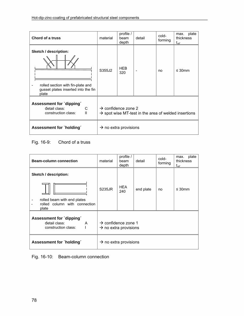
Hot-dip-zinc-coating of prefabricated structural steel components
78
Chord of a truss material
profile / beam depth
detail cold-forming
max. plate thickness tref
Sketch / description:
- rolled section with fin-plate and gusset plates inserted into the fin
plate
S355J2 HEB 320
- no ≤ 30mm
Assessment for `dipping´ detail class: C
construction class: II
confidence zone 2 spot wise MT-test in the area of welded insertions
Assessment for `holding´
no extra provisions
Fig. 16-9: Chord of a truss Beam-column connection material
profile / beam depth
detail cold-forming
max. plate thickness tref
Sketch / description:
- rolled beam with end plates - rolled column with connection
plate
S235JR HEA 240
end plate no ≤ 30mm
Assessment for `dipping´ detail class: A
construction class: I
confidence zone 1 no extra provisions
Assessment for `holding´
no extra provisions
Fig. 16-10: Beam-column connection
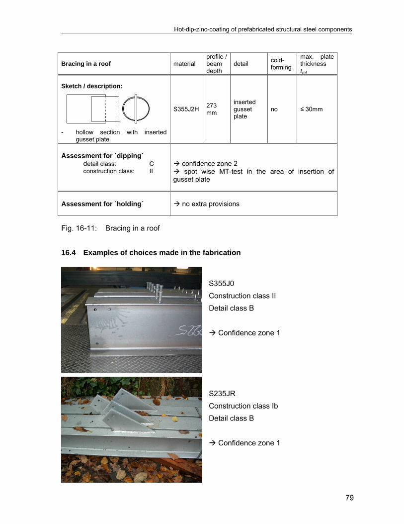
Hot-dip-zinc-coating of prefabricated structural steel components
79
Bracing in a roof material
profile / beam depth
detail cold-forming
max. plate thickness tref
Sketch / description:
- hollow section with inserted
gusset plate
S355J2H 273 mm
inserted gusset plate
no ≤ 30mm
Assessment for `dipping´ detail class: C
construction class: II
confidence zone 2 spot wise MT-test in the area of insertion of gusset plate
Assessment for `holding´
no extra provisions
Fig. 16-11: Bracing in a roof 16.4 Examples of choices made in the fabrication
S355J0
Construction class II
Detail class B
Confidence zone 1
S235JR
Construction class Ib
Detail class B
Confidence zone 1
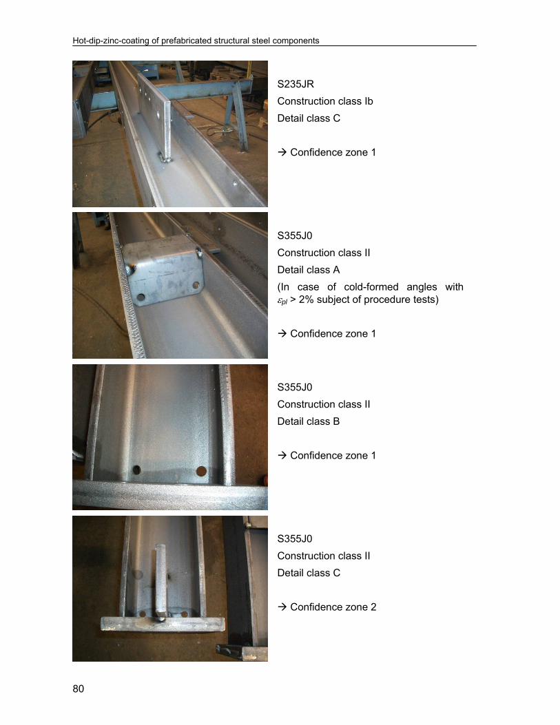
Hot-dip-zinc-coating of prefabricated structural steel components
80
S235JR
Construction class Ib
Detail class C
Confidence zone 1
S355J0
Construction class II
Detail class A
(In case of cold-formed angles with pl > 2% subject of procedure tests)
Confidence zone 1
S355J0
Construction class II
Detail class B
Confidence zone 1
S355J0
Construction class II
Detail class C
Confidence zone 2

Hot-dip-zinc-coating of prefabricated structural steel components
81
S355J0
Construction class II
Detail class C
Confidence zone 2
S235JR
Construction class II
Detail class B
Confidence zone 1
S235JR
Construction class I
Detail class B
(In case of cold-formed angles with pl > 2% subject of procedure tests)
Confidence zone 1
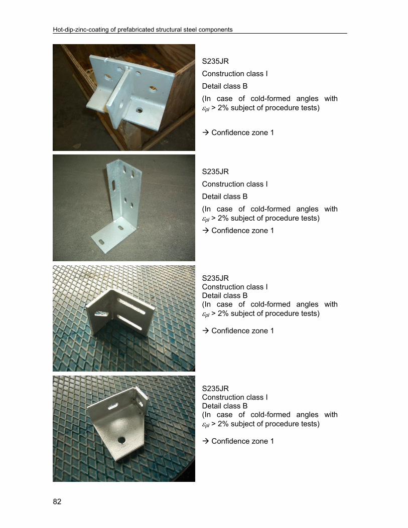
Hot-dip-zinc-coating of prefabricated structural steel components
82
S235JR
Construction class I
Detail class B
(In case of cold-formed angles with pl > 2% subject of procedure tests)
Confidence zone 1
S235JR
Construction class I
Detail class B
(In case of cold-formed angles with pl > 2% subject of procedure tests)
Confidence zone 1
S235JR Construction class I Detail class B (In case of cold-formed angles with pl > 2% subject of procedure tests) Confidence zone 1
S235JR Construction class I Detail class B (In case of cold-formed angles with pl > 2% subject of procedure tests) Confidence zone 1

Hot-dip-zinc-coating of prefabricated structural steel components
83
S235JR Construction class I Detail class B (In case of cold-formed angles with pl > 2% subject of procedure tests) Confidence zone 1
S235JR Construction class I Detail class B Confidence zone 1
S355J0 Construction class I Detail class C Confidence zone 1
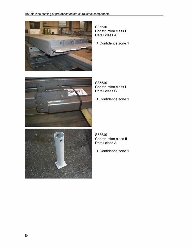
Hot-dip-zinc-coating of prefabricated structural steel components
84
S355J0 Construction class I Detail class A Confidence zone 1
S355J0 Construction class I Detail class C Confidence zone 1
S355J0 Construction class II Detail class A Confidence zone 1
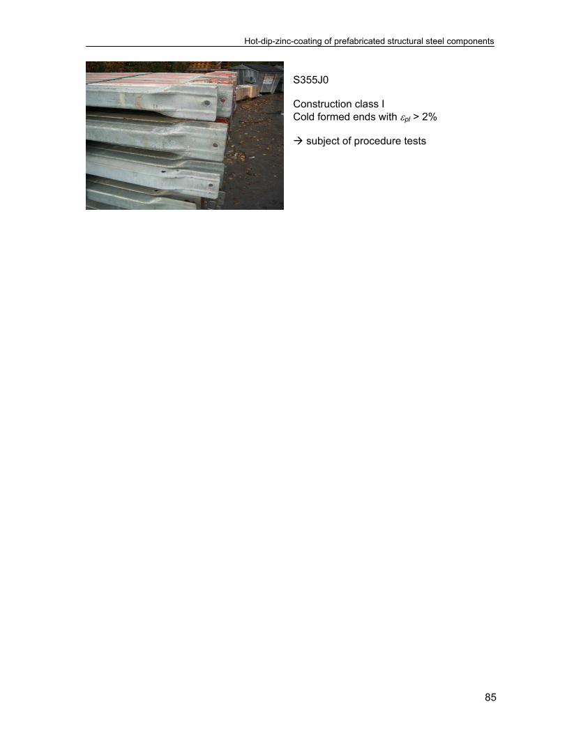
Hot-dip-zinc-coating of prefabricated structural steel components
85
S355J0 Construction class I Cold formed ends with pl > 2% subject of procedure tests


Hot-dip-zinc-coating of prefabricated structural steel components
87
17 Procedure tests (1) Where the standard assumptions e.g. related to the aspects in fig. 17-1 which
have been made for applying the assessment methods in section 13 to 15 are not met, “procedure tests” with additional non-destructive testing may be applied to achieve hot-dip galvanizing without LMAC.
(2) The “procedure tests” after acknowledgement identify the particular conditions to
be met for the structural detailing, the fabrication of the component and the galvanizing process that have been varied.
(3) The basis of “procedure tests” is a provisional instruction for galvanizing which
comprises all relevant aspects of design, steel products, fabrication and galvanizing procedure and of the NDT to be carried out after galvanizing.
(4) If the testing is successful the applicant (steel fabricator and zinc coater) may get
an acknowledgement according to the legal conditions.
Examples for variations Extend of NDT Cold cut edges Cold forming Ratio of plate thickness Structural detailing Latticed structure without joints Longer holding time
Confidence Zone 3 according to fig. 14-1 however with
testing all details
Figure 17-1: Extend of testing for the procedure tests

Hot-dip-zinc-coating of prefabricated structural steel components
89
18 Supplementary rules for execution of hot-dip-zinc coating 18.1 General (1) The assessment methods based on numerical calculations as given in section 13
and 14 or based on the classification method as given in section 15 include the concept of confidence zones which require that:
1. testing of the galvanizing procedure is carried out to secure that the
conditions for works as assumed are met and remain stable (independent on time),
2. testing after the galvanizing process reveals that no cracks have occurred and hence the assessment procedure is safe-sided.
(2) An important issue of stability of conditions for the galvanizing process is the
control of the zinc melt. (3) Testing after the galvanizing process is the non destructive testing (NDT) of
galvanized components with visual inspections (100 %) and a limited number of MT-tests, where required by the designer (e.g. according to the Confidence Zone resulting from the assessment) or where required after visual tests.
(4) In the following examples for specifying rules for the control of the zinc melt and
for NDT-testing of galvanized components are given, which have been taken from [75].
18.2 Control of chemical composition of the zinc melt 18.2.1 Relevant Standards QM-documentation of the zinc coater EN ISO 1461 Requirements for accident prevention 18.2.2 Equipment, tools and sampling (1) The outfit for personal protection and the sampling procedure may depend on the
regional health and safety requirements. (2) Sampling should be carried out from a well mixed zinc bath sufficiently long after
measures for maintenance of the zinc bath (e.g. for refurbishment the alloy, etc.).
Note: This requirement would be met if sampling would be made under regular working conditions at least 1 hour after begin of production.
(3) The sample should be taken always at the same spot of the zinc bath.
Note: E.g. the position should be located at the middle of the long side of the tank, at a distance of 20 cm from the edge and 20 cm below the surface.

Hot-dip-zinc-coating of prefabricated structural steel components
90
Note: A proposal for a device for sampling is given in fig. 18-1. This should be, once the top opened, dipped slowly at an angle to the bath surface until the depth mark is reached.
Figure 18-1: Proposal for a device for sampling
(4) The device for sampling should be moved in the zinc bath sideways (to the right
and left) for 2 minutes. (5) After that the top of the device should be closed right down by turning. (6) The device should be taken out vertically quickly from the zinc bath (Attention to
heat protective gloves necessary for regaining one´s grip to the hot bar of the sampling device).
(7) Once outside the zinc tank the bottom part of the sampling device with the
samples should be dipped into water, with the samples only partly submerged until solidification and then fully submerged for cooling.
(8) After cooling the samples should be taken from the device, one for the analysis,
the other as reserve for the quality check. (9) The samples should be marked with a permanent marker.

Hot-dip-zinc-coating of prefabricated structural steel components
91
(10) The sampling should be documented in a data sheet for the control
documentation. 18.2.3 Method for analysis (1) The analysis should only be carried out in laboratories laid down in the QM
system. (2) The analysis of the zinc sample should give quantitative values for the following
elements (8-elements) to characterize sufficiently the composition of the zinc alloy and to check the requirements given in fig. 7-7:
- aluminium (Al) - lead (Pb) - cadmium (Cd) - iron (Fe) - copper (Cu) - nickel (Ni) - bismuth (Bi) - tin (Sn)
18.3 Non destructive testing procedures for zinc coated structural components 18.3.1 General (1) The non destructive testing (NDT) of zinc coated structural components to detect
possible cracks under the zinc coat should be performed with appropriate testing methods, e.g. the magnetic flux tests (MT) taking account of:
- reduced sensitivity from zinc coat thicknesses tZn 50 m (see EN 1290,
Annex A1) - limited accessibility in the area of spandrels from web, flange and
endplates. (2) The following specification applies to the MT-procedure and contains
requirements for the test parameters to achieve an optimum sensitivity for test. 18.3.2 References to standards EN 473 Qualification and certification of personal for NDT EN ISO 9934-1 Magnetic flux testing – General basis EN ISO 9934-2 Magnetic flux testing – Means for testing EN ISO 9934-3 Magnetic flux testing – Equipment for magnetizing
EN ISO 3059 Magnetic flux testing and penetration testing – Conditions for visual testing
Hot-dip-zinc-coating of prefabricated structural steel components
92
18.3.3 Test personal (1) The NDT-checks may only be carried out by qualified personal (at least level II-
requirement according to EN 473 for the MT-procedure). 18.3.4 Preparation of surface for testing (1) The surfaces should be checked visually (VT) and cleaned where appropriate.
Locations where the visual test gives indications should be included in the list of spots prepared by the designer for MT-checks.
(2) After cleaning, the surfaces for tests should be free of any soiling impeding
appropriate testing. 18.3.5 Testing equipment and means for testing (1) The testing equipment and the means for testing should comply with the relevant
standards. 18.3.6 Check of sufficient magnetizing of the testing system (1) Sufficient magnetizing of the steel surface should be achieved by an appropriate
level of the strength of the magnetic field. (2) The magnetizing should be checked by measuring the tangential strength of the
magnetic field. The strength measured as closely as possible at the surface on the basis of the
Hall-effect should attain a value of 4 kA/m (40 A/cm). (3) Electric power generators used should give sufficient power supply. 18.3.7 Check of sufficient magnetizing for a project (1) Before starting the test works (at least once a day) the magnetizing should be
checked with a reference component. 18.3.8 Means for testing (1) The means for testing should comply with the requirements of EN ISO 9934-2
and the particular conditions from reduced sensitivity by the zinc coat. Note: The following means for testing have proved to be suitable: - MR 76 MR-Chemie - NRS 107 Helling - Ferroflux-Pulver-Suspension 690.2

Hot-dip-zinc-coating of prefabricated structural steel components
93
18.3.9 Visual evaluation (1) The following conditions apply for the visual evaluation using black means of
testing:
- the surface should be controlled with an illumination strength of at least 500 Lux.
18.3.10 Area to be tested (1) The areas to be tested should be determined by the designer, see fig. 18-2.
These areas should be supplemented by spots where visual testing has identified indications.
(2) Magnetizing should by achieved by hand-magnets. Sufficient time for post-
magnetizing should be taken into account.
Note: A sufficient time for magnetizing of 6 s and a subsequent post magnetizing time of 6 s would provide sufficient time for the formation of indications.
(3) The overlapping of areas to be tested should be sufficient. 18.3.11 Limits for confidence (1) Linear indications caused by material discontinuities (e.g. cracks, fusion lacks,
flow over of weld material) are not permitted. (2) Where the existence of cracks is suspected, the test should be performed without
the zinc coat after grinding. (3) Unless otherwise specified by the designer indications with lengths 3 mm may
be disregarded. Note: In areas with high local plastic strains which may occur in the parent material by weld-
shrinkage adjacent to large welds, indications may be found inspite of fulfilling all conditions to avoid LMAC. In case of such indications, it has to be decided whether these indications mean through cracks or only surface cracks and whether further measures, e.g. grinding, is necessary.
18.3.12 Demagnetizing (1) A demagnetizing of welded structural components normally is not necessary. 18.3.13 Treatment of structural components with faults (1) Any decision for the treatment of structural components with faults should be
made together with the designer.

Hot-dip-zinc-coating of prefabricated structural steel components
94
Frequently used typical details where NDT-methods may give
indications for cracks Detail class
Free beam end
Full end plates
Holes in the web at the end of the
beam with d > 25mm
Transverse stiffener *) connected to
2 edges (end distance e > h)
Transverse stiffener connected to 3 edges
(end distance e > h)
Transverse stiffener with flange connected
to 3 edges (end distance e > h)
Transverse stiffener attached to the flange
Shear studs welded to top flange
*)drainage holes where necessary in end-plates or stiffeners
A
Drainage holes in the web
Holes in the web at the end of the
beam with d < 25mm
At full welding of fin plates or
gusset plates
Cope cut
r ≥ 10 mm, lcope < 150 mm
Attachments with turn around welds
Attachment with intermitted welds
B
At the weld around plates inserted
into the web of profiles or into tubes
In the web of slender profiles below
half cover end plates
Cope cut
r < 10 mm, lcope ≥ 150 mm
C
Figure 18-2: Areas to be tested

Hot-dip-zinc-coating of prefabricated structural steel components
95
18.3.14 Documentation of the tests (1) The documentation of the tests should comply with the requirements in EN ISO
9934-1. (2) The location and the sizes of faults should be clearly documented.

Hot-dip-zinc-coating of prefabricated structural steel components
97
19 Conclusion (1) This JRC-Scientific and Technical Report gives a survey on the state-of-the-art in
explaining the causes of liquid metal assisted cracking (LMAC) of prefabricated structural steel components in the zinc melt during hot-dip galvanizing that may impair their structural safety. It also offers ways to avoid it.
(2) Various parameters related to:
- the design of prefabricated components, - the fabrication of prefabricated component, - the zinc alloy and the galvanizing process.
control the likelihood for occurrence of this phenomenon, so that information across design, fabrication and galvanizing need to be taken into account to produce hot-dip-galvanized structural components that are free from cracks.
(2) This report also demonstrates mechanical models suitable to consider cracking in
the zinc melt as a limit state related to plastic strain requirements on one side and ultimate plastic strain resistances on the other side.
(3) To determine such plastic strain resistances a new testing procedure with small
scale LNT-test specimen has been developed, that reveals the interaction between the steel material, zinc alloy and galvanizing process and time. To determine plastic strain requirements numerical simulations of the “stationary” strain field from the fabrication of components and of the “non-stationary” strain fields from the dipping and holding processes are necessary.
(4) For practical use simplified methods have been derived from the results of such
limit state studies, either with simplified mechanical models for numerical assessment or with classification methods, that do not need any calculation. These models are based on standardized conditions for:
- choice of profiles and steel, - structural detailing considering notch effects, - galvanizing process, - inspection and testing.
(5) Due to various uncertainties related to compliance with these conditions and to
the simplified assessment model used, confidence zones are introduced for which rules for inspection and non-destructive testing are defined, so that the combination of assessment and testing produces the reliability required for avoiding liquid metal assisted cracking.
(6) Worked examples complete the survey; they give proof that the methods
developed are workable and applicable to practical use.

Hot-dip-zinc-coating of prefabricated structural steel components
99
20 Literature [1] Mitteilungen des Bayerischen Staatsministeriums des Inneren; Rissbildung an
feuer-verzinkten Stahlkonstruktionen, 24.05.2006 sowie ähnliche Mitteilungen der Obersten Baubehörden anderer Bundesländer
[2] Weber, L., Hoffmann, J.: Communiqué der Fa. Arcelor-Mittal zur Verzinkungsriss-Problematik, 2007
[3] Katzung W., Schulz W.-D.: Beitrag zum Feuerverzinken von Stahlkonstruktionen - Ursachen und Lösungsvorschläge zum Problem der Rissbildung. Stahlbau 74 (2005), S. 258-273
[4] Breitschaft, G., Ulbrich D.: Rissbildung in feuerverzinkten Stahlkonstruktionen, DIBt Mitteilungen, 37 (2006) 6, S. 219-221
[5] DIN EN 1290: Zerstörungsfreie Prüfung von Schweißverbindungen – Magnetpulver-Prüfung von Schweißverbindungen, September 2002
[6] Feldmann M., Pinger T., Tschickardt D.: Ursachen und Einflüsse auf die Rissbildung beim Feuerverzinken von großen Stahlkonstruktionen, GAV- Forschungskolloquium Hannover 2007
[7] Nies, H.. Schambiel, G., Stiefel, B.: Die Problematik der Rissbildung beim Feuerverzinken, Der Praktiker – DVS Verlag, Seite 178 – 185, 6/2007
[8] Feldmann M., Pinger T., Tschickardt D.: Cracking in large steel structures during hot dip galvanizing. Intergalva 2006, Neapel 2006
[9] Kinstler, T J.: Current Knowledge of the Cracking during Galvanizing, Galva Science LLC, Canada, 2005
[10] Feldmann M.: Feuerverzinken von großen Stahlkonstruktionen; Rissschäden – Ursache, Hintergründe und Vermeidung, Gemeinschaftsausschuss Feuerverzinken e.V., Forschungskolloquium Wiesbaden, Nov. 2003
[11] Feldmann M.: A new Aspect of Crack Assessment of Galvanized Steel Structures, 4th Eurosteel Conference, Maastricht (NL), May 2005
[12] Sedlacek G., Dahl W., Hoffmeister B., Kühn B., Feldmann M., Pinger T., Langenberg P., Blum M., Grotmann D., Eichenmüller H.: Zur sicheren Anwendung feuerverzinkter Träger. Stahlbau 73 (2004), S. 427-437
[13] Herold, H.; Woywode, N.; Pieschel, J.: Fertigungsbedingte Risse durch ungünstige schweißtechnische Gestaltung und Ausführung, Z. Metallk., S.232-236, 2001
[14] Pargeter, R.: Liquid metal penetration during hot dip galvanizing, Internetveröf-fentlichung, The Welding Institute, Great Abington, Cambridge, 2003
[15] Herbsleb, G.; Pöpperling, R.: Dehnungsinduzierte Spannungsrisskorrosion an Stählen, Werkstoffe und Korrosion 29 (1978) S. 732-739
[16] Engell, H.-J.; Speidel, M. O.: Ursachen und Mechanismen der Spannungsrisskorrosion, Werkstoffe und Korrosion 20 (1969) S. 281-300
[17] Friehe, W.: Dehnungsinduzierte Spannungsrisskorrosion in Flüssigmetallen, Werkstoffe und Korrosion 29 (1978) S. 747-753
[18] Old, C. F.; Trevena, P.: Embrittlement of zinc by liquid metals, Metal Science, p. 487-495, 1979
[19] Old, C. F.: Liquid metal embrittlement of nuclear materials, Journal of nuclear materials 92, p. 2-25, 1980
[20] Old, C. F.: Micromechanisms of crack growth in liquid metal environments, Metal science, p. 433-440, 1980
[21] Rostoker, W.; McCaughey, J. M.; Markus, H.: Embrittlement by Liquid Metals, Reinhold Publishers, New York, 1960

Hot-dip-zinc-coating of prefabricated structural steel components
100
[22] Westwood, A. R. C.; Kamdar, M. H.: In Environment Sensitive Mechanical Behaviour, A. R. C. Westwood and N. S. Stoloff, Ed., TMS-AIME Conference 35, Gordon and Breach, 1966 p. 581
[23] Pargeter, F. W. J.; Ives, M. B.: Grain Size Dependence of Fracture in Copper-Aluminium Alloys Embrittled by Mercury, Canadian Journal of Physics 45, p. 1234, 1967
[24] Hancock, P. C.; Ives, M. B.: The role of plastic deformation in liquid metal embrittlement, Canadian metallurgical quarterly, Volume 10, 1971
[25] Rädeker, W.: Die Erzeugung von Spannungsrissen in Stahl durch flüssiges Zink, Stahl u. Eisen 73 (1953), S. 654-658
[26] Nieth, F.: Festigkeitsfragen im Zusammenhang mit der Feuerverzinkung, Dissertation D17, Darmstadt, 1965
[27] Funke, P.; Klemens, D.: Untersuchung über den Einfluss des Zinks und seiner Legierungselemente auf die Rissbildung von Stählen, TU Clausthal, Projekt im Rahmen des Forschungs- und Entwicklungsprogramm „Korrosion und Korrosionsschutz, 1980
[28] Klemens, D.: Inbetriebnahme von Verzinkungskesseln, Spannungen im Kesselmaterial und Rissgefährdung durch unterschiedliche Zinkschmelzen. Gemeinschaftsausschuss Verzinken e.V. Düsseldorf, Vortrags- und Diskussionsveranstaltung GAV 1983
[29] Schwenk, W. „Einflussgrößen bei der Korrosion von Stählen unter Rissbildung mit besonderer Berücksichtigung der mechanischen Belastungsparameter“ in Festigkeitsverhalten höherfester schweißbarer Baustähle / Korrosion“, VEB Deutscher Verlag für Grundstoffindustrie, Leipzig, 1983
[30] Herbsleb, G.; Pfeiffer, B.; Pöpperling, R.; Schwenk, W.: Die Wirkung mechanischer Einflussgrößen bei der Risskorrosion von Kohlenstoff-Mangan-Stählen, Z. Werkstoff-tech, 1978
[31] Schubert, P.; Schulz, W.-D.; Katzung, W.; Rittig, R.: Struktur und Eigenschaften von Feuerzinküberzügen, Metall 53, S. 260-268, 1999
[32] Merkblatt 329 - Korrosionsschutz durch Feuerverzinken (Stückverzinken), Stahl-Informations-Zentrum und Gemeinschaftsausschuss Verzinken e.V., Düsseldorf
[33] Sandelin, R. W.: Galvanizing characteristics of different types of steel, Wire and Wire Products No. 12, 1940
[34] Klemens, D., Kaszàs, S.: Untersuchung der Spannungsrisskorrosion von Baustählen in flüssigem Zink. Werkstoffe und Korrosion 43(1992), 561-564.
[35] Nürnberger, U.; Menzel, K.: „Rissbildung beim Feuerverzinken von Feinkorn-baustählen“, Abschlussbericht in der Forschungs- und Materialprüfungsanstalt Baden-Württemberg, 1998
[36] Kikuchi, M.: Liquid metal embrittlement of steels by molten zinc, Proceedings of the 23rd Japan Congress on Material Research, 1980
[37] Kikuchi, M.; Lezawa, T.: Liquid Metal Embrittlement of Steels in Molten Zinc, Journal of the Society of Naval Architects, Japan, Vol. 149, No. 6, 1981, pp. 298-305
[38] Kikuchi, M.: Study on fracture mechanisms of liquid metal embrittlement cracking of steels in molten zinc, Proceedings of the 24th Japan Congress on Material Research, 1981
[39] Kikuchi, M.: Liquid Metal Embrittlement Cracking of Notched Rectangular Steel Plate in Molten Zinc, Journal of the Society of Materials Science, Japan, Vol. 30, No. 329, 1981, pp. 194-199
[40] Kikuchi, M.: Liquid Metal Embrittlement of Steels during Hot Dip Galvanizing, Tetsu to Hagane, (Iron and Steel), Vol. 68, Number 14, 1982, p. 1870-1879
Hot-dip-zinc-coating of prefabricated structural steel components
101
[41] Abe, H.; Lezawa, T.; Kanaya, K.; Yamashita, T.; Aihara, S.; Kanazawa, S.: Study of HAZ cracking of hot-dip galvanizing steel bridges, International Institute of Welding, IIW Doc. IX-1795-94
[42] Kikuchi, M.; Lezawa, T.: Effect of Stress-Concentration Factor on Liquid Metal Embrittlement Cracking of Steel in Molten Zinc, Journal of the Society of Materials Science, Japan, Vol. 31, No. 352, 1982, p. 271-276
[43] Kikuchi, M.: Prevention of distortion and of crack initiation, Proceedings 13th International Galvanizing Conference, London, 1982, European General Galvanizers Association
[44] Bargel, H.-J., Schulze, G., Cev Gülec, S., Aran, A.: Malzene Bilgisi, Cilt II, J.T.Ü. Makina Fakültesi, Istanbul, 1995
[45] DIN EN 10025: Warmgewalzte Erzeugnisse aus Baustählen, 2006 [46] DIN EN 1461: Durch Feuerverzinken auf Stahl aufgebrachte Zinküberzüge
(Stückverzinken) – Anforderungen und Prüfungen, März 1999 [47] DASt- Richtlinie 009:2005-01: Stahlsortenauswahl für geschweißte Stahlbauten,
Deutscher Stahlbauverband, Stahlbau Verlags- und Service GmbH, Düsseldorf, 2005
[48] DIN EN 1993-1-10:2005-07: Eurocode 3: Bemessung und Konstruktion von Stahlbauten- Teil 1-10: Stahlsortenauswahl in Hinblick auf Bruchzähigkeit und Eigenschaften in Dickenrichtung, Bemessungsregeln für den Stahlbau, Beuth- Verlag, Berlin, 2005
[49] Peil, U.; Wichers, M.: Schweißen unter Betriebsbeanspruchungen – Werkstoffkennwerte für einen S355J2G3 unter Temperaturen bis 1200°C, Stahlbau 73 (2004), H. 6, S. 400-416
[50] Feldmann M., Bleck W., Langenberg P., Pinger T., Tschickardt D., Völling A., Ermittlung der Rissanfälligkeit beim Stückverzinken, MP Materials Testing 49 (2007), S. 223-231
[51] Petersen, C.: Stahlbau – Grundlagen der Berechnung und baulichen Ausbildung von Stahlbauten, Vieweg & Sohn Verlagsgesellschaft mbH, 1993
[52] Roik, K.: Vorlesungen über Stahlbau, Verlag Ernst & Sohn, 1983 [53] Malisius, R.: Schrumpfungen, Spannungen und Risse beim Schweißen,
Deutscher Verlag für Schweißtechnik (DVS), Düsseldorf, 1957 [54] Nitschke- Pagel, T.; Dilger, K.: Eigenspannungen in Schweißverbindungen – Teil
1: Ursachen der Eigenspannungsentstehung beim Schweißen, Verlag für Schweißen und verwandte Verfahren, Düsseldorf, Schweißen und Schneiden 58 (2006), H.9, S. 466-479
[55] Radaj, D.: Wärmewirkungen des Schweißens, Temperaturfeld, Eigenspannungen, Verzug. Springer-Verlag, Berlin, 1988
[56] Nitschke-Pagel, T., Wohlfahrt, H: Residual stresses in welded joints - sources and consequences. Proc. 6. European Conference on Residual Stresses S.215/24. Trans Tech Publications, Suisse 2002
[57] Pinger, T.: Zur Vermeidung der Rissbildung an Stahlkonstruktionen beim Feuerverzinken bei besonderer Berücksichtigung der flüssigmetallinduzierten Spannungsrisskorrosion, Diss. RWTH Aachen, 2009
[58] Neuber, Heinz: Kerbspannungslehre - Theorie der Spannungskonzentration; genaue Berechnung der Festigkeit. Berlin, u.a.: Springer, 1985
[59] Galvanizing Structural Steelwork – An approach to the management of liquid metal assisted cracking, BCSA and GA publication No. 40/05
[60] Empfehlungen zur Prüfung feuerverzinkter Stahlkonstruktionen mittels modifiziertem MT-Verfahren, Lehrstuhl für Stahlbau, RWTH Aachen, 2006
Hot-dip-zinc-coating of prefabricated structural steel components
102
[61] Prüfanweisung für die zerstörungsfreie Prüfung von geschweißten feuerverzinkten Stützenjochen Ausführung 98, Nr. PAST0100, Doppelmayr Seilbahnen GmbH, Wolfurt
[62] DIN 18800 - 1: Stahlbauten - Bemessung und Konstruktion, November 1990 [63] DIN 18800 – 7: Stahlbauten – Ausführung und Herstellerqualifikation, September
2002 [64] DIN EN ISO 5817: Schweißen – Schmelzschweißverbindungen an Stahl, Nickel,
Titan und deren Legierungen (ohne Strahlschweißen) – Bewertungsgruppen von Unregelmäßigkeiten (ISO 5817:2003 + Cor. 1:2006); Deutsche Fassung EN ISO 5817:2003 + AC:2006
[65] Vermeidung von Rissen beim Feuerverzinken von großen Stahlkonstruktionen mit hochfesten Stählen, GAV-AiF- Forschungsvorhaben 14545 N/1, Lehrstuhl für Stahlbau und Leichtmetallbau und Institut für Eisenhüttenkunde, RWTH Aachen, Abschlussbericht 2007
[66] RFCS- Forschungsprojekt TGS5 – RFS CR 03021 „Failure Mechanisms During Galvanizing – FAMEGA“, Aachen, Rotherham, Esch-sur-Alzette, Kaiserslautern, Santander, Abschlussbericht 2007
[67] Rädeler, W.; Haarmann, R.: Angriffsarten des Zinks auf Stahl bei der Feuerverzinkung, Stahl und Eisen 59 (1939), S. 1217-1227
[68] Breitschaft, G.: Schäden an feuerverzinkten Stahlkonstruktionen, Schreiben vom 09.05.2006
[69] Rädeler, W.: Der interkristalline Angriff von Metallschmelzen auf Stahl, Werkstoffe und Korrosion 24 (1973), S. 851-859
[70] „Konstruktionsgerechtes Verzinken, verzinkungsgerechtes Konstruieren“, DASt- Richtlinie 022, in Vorbereitung
[71] Markus Feldmann, Thomas Pinger, Dirk Tschickardt, Peter Langenberg, Alexander von Richthofen, Peter Karduck: Rissbildung durch Flüssigmetallversprödung beim Feuerverzinken von Stahlkonstruktionen. In: Stahlbau-Kalender, hrsgn. von U. Kuhlmann. Berlin: Ernst & Sohn 2008
[72] Markus Feldmann, Thomas Pinger, Dirk Tschickardt, Wolfgang Bleck, Alexander Völling, Peter Langenberg: Analyse der Einflüsse auf die Rissbildung infolge Flüssigmetallversprödung beim Feuerverzinken, Stahlbau 77 (2008), S. 46-61
[73] Markus Feldmann, Thomas Pinger, Gerhard Sedlacek, Dirk Tschickardt: Die neue DASt-Richtlinie zur Vermeidung von Rissbildung beim Feuerverzinken, Stahlbau 77 (2008), S. 734-742
[74] Kinstler, T.J.: Current knowledge of the cracking of steels during galvanizing. GalvaScience for AISC http://www.aisc.org/Content/ContentGroups/Engineering_and_Research/Research1/Final5906.pdf
[75] DASt-Richtlinie 022 – Feuerverzinken von tragenden Stahlbauteilen, Deutscher Ausschuß für Stahlbau, October 2009
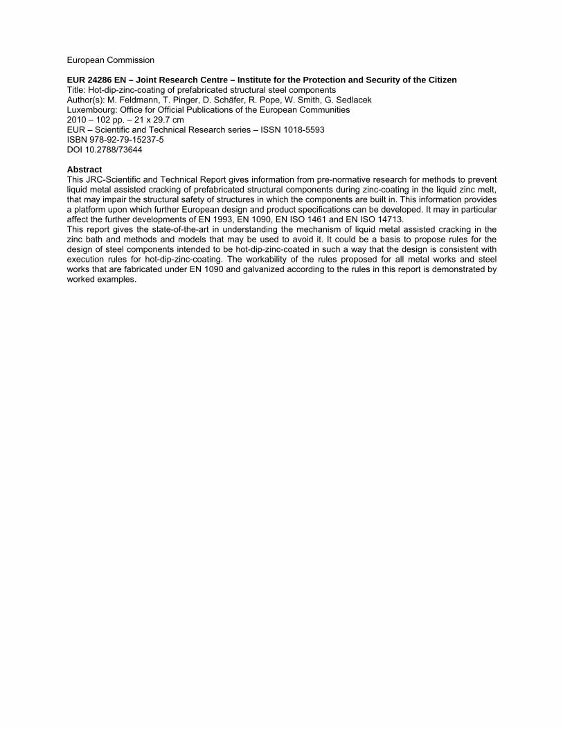
European Commission EUR 24286 EN – Joint Research Centre – Institute for the Protection and Security of the Citizen Title: Hot-dip-zinc-coating of prefabricated structural steel components Author(s): M. Feldmann, T. Pinger, D. Schäfer, R. Pope, W. Smith, G. Sedlacek Luxembourg: Office for Official Publications of the European Communities 2010 – 102 pp. – 21 x 29.7 cm EUR – Scientific and Technical Research series – ISSN 1018-5593 ISBN 978-92-79-15237-5 DOI 10.2788/73644 Abstract This JRC-Scientific and Technical Report gives information from pre-normative research for methods to prevent liquid metal assisted cracking of prefabricated structural components during zinc-coating in the liquid zinc melt, that may impair the structural safety of structures in which the components are built in. This information provides a platform upon which further European design and product specifications can be developed. It may in particular affect the further developments of EN 1993, EN 1090, EN ISO 1461 and EN ISO 14713. This report gives the state-of-the-art in understanding the mechanism of liquid metal assisted cracking in the zinc bath and methods and models that may be used to avoid it. It could be a basis to propose rules for the design of steel components intended to be hot-dip-zinc-coated in such a way that the design is consistent with execution rules for hot-dip-zinc-coating. The workability of the rules proposed for all metal works and steel works that are fabricated under EN 1090 and galvanized according to the rules in this report is demonstrated by worked examples.


How to obtain EU publications Our priced publications are available from EU Bookshop (http://bookshop.europa.eu), where you can place an order with the sales agent of your choice. The Publications Office has a worldwide network of sales agents. You can obtain their contact details by sending a fax to (352) 29 29-42758.

The mission of the JRC is to provide customer-driven scientific and technical support for the conception, development, implementation and monitoring of EU policies. As a service of the European Commission, the JRC functions as a reference centre of science and technology for the Union. Close to the policy-making process, it serves the common interest of the Member States, while being independent of special interests, whether private or national.
L
B-N
A-24286-E
N-C