Embed Size (px)
Citation preview
EPFL / PSI February 2010, N Holtkamp Page 1
Overview of the Status of the ITER Project
Norbert HoltkampPrincipal Deputy Director General of the ITER Organization
Acknowledgements: ITER team, Domestic Agencies and all collaborating institutions
EPFL / PSI February 2010, N Holtkamp Page 2
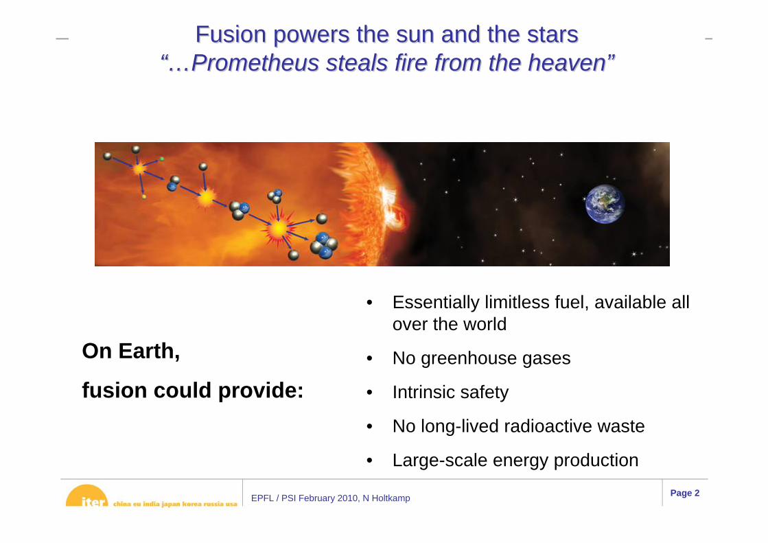
Fusion powers the sun and the starsFusion powers the sun and the stars“…“…Prometheus steals fire from the heavenPrometheus steals fire from the heaven””
• Essentially limitless fuel, available all over the world
• No greenhouse gases
• Intrinsic safety
• No long-lived radioactive waste
• Large-scale energy production
On Earth,
fusion could provide:
EPFL / PSI February 2010, N Holtkamp Page 3
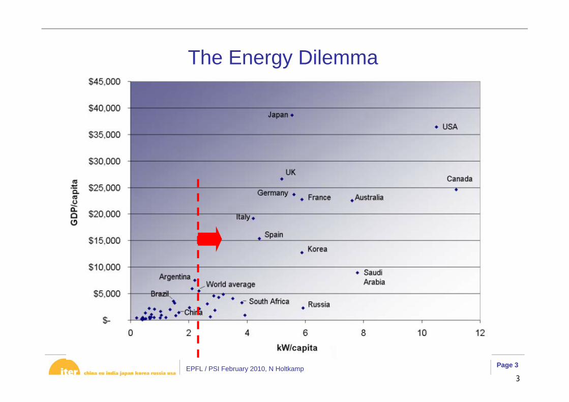
The Energy Dilemma
3

EPFL / PSI February 2010, N Holtkamp Page 4
Theorist’s view of the History of Fossil Fuel Use….
C. Llewellyn-Smith

EPFL / PSI February 2010, N Holtkamp Page 5
Lithium compound
Not to scale !
A Fusion power plant would be like…
EPFL / PSI February 2010, N Holtkamp Page 6
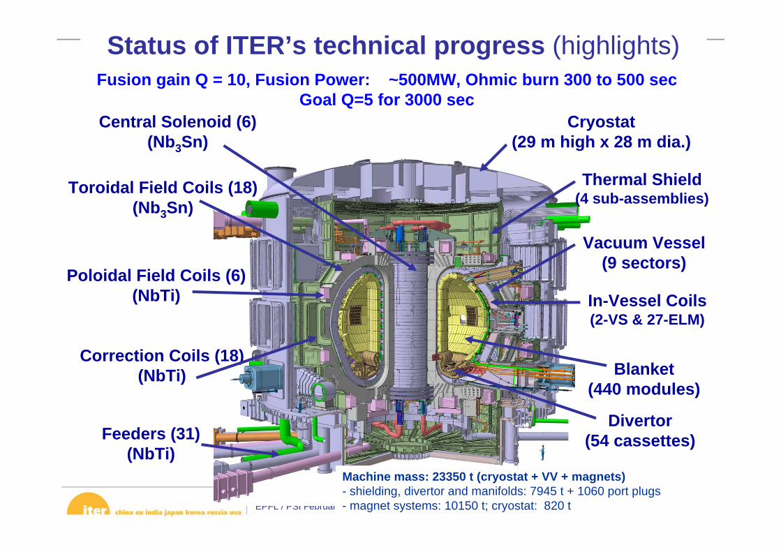
Feeders (31)(NbTi)
Correction Coils (18)(NbTi)
Poloidal Field Coils (6)(NbTi)
Toroidal Field Coils (18)(Nb3Sn)
Central Solenoid (6)(Nb3Sn)
Divertor (54 cassettes)
Blanket (440 modules)
Cryostat (29 m high x 28 m dia.)
Vacuum Vessel (9 sectors)
Thermal Shield (4 sub-assemblies)
In-Vessel Coils(2-VS & 27-ELM)
Status of ITER’s technical progress (highlights)Fusion gain Q = 10, Fusion Power: ~500MW, Ohmic burn 300 to 500 sec
Goal Q=5 for 3000 sec
Machine mass: 23350 t (cryostat + VV + magnets)- shielding, divertor and manifolds: 7945 t + 1060 port plugs- magnet systems: 10150 t; cryostat: 820 t
EPFL / PSI February 2010, N Holtkamp Page 7
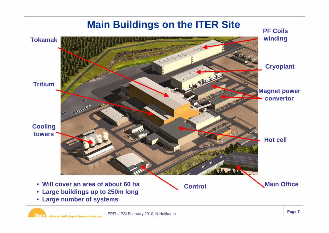
Main Buildings on the ITER Site
• Will cover an area of about 60 ha• Large buildings up to 250m long• Large number of systems
Tritium
Cryoplant
Magnet power convertor
Cooling towers
Hot cell
TokamakPF Coils winding
Main OfficeControl
EPFL / PSI February 2010, N Holtkamp Page 81
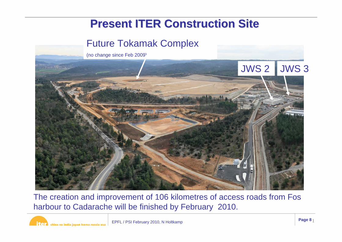
PresentPresent ITER Construction Site ITER Construction Site
JWS 2 JWS 3
The creation and improvement of 106 kilometres of access roads from Fosharbour to Cadarache will be finished by February 2010.
Future Tokamak Complex (no change since Feb 2009)

EPFL / PSI February 2010, N Holtkamp Page 9
ITER ITER –– Key FactsKey Facts• Mega-Science Project among 7
Members: China, EU, India, Japan, Korea, Russia & US
• Designed to produce 500 MW of fusion power for an extended period of time
• 10 years construction, 20 years operation
• Cost: ~5.4 billion Euros approved for construction, and ~5.5 billion for operation and decommissioning
• EU 5/11, other six parties 1/11 each. Overall reserve of 10% of total.
European Union
CN
IN
RF
KO
JP
US

EPFL / PSI February 2010, N Holtkamp Page 10
Procurement Sharing- A unique feature of ITER is that almost all of the
machine will be constructed through in kindprocurement from the Parties with essentially every party involved in every component.

EPFL / PSI February 2010, N Holtkamp Page 11
PDDG house

EPFL / PSI February 2010, N Holtkamp Page 12
ITER Organization Structure
Tim Watson

EPFL / PSI February 2010, N Holtkamp Page 13
ITER as a start up -> Staffing
• As of 31 May 2009, the ITER Organization has a total of 364 staff, including 254 professional and 110 technical support staff.
• In addition approximately 250 contract staff
Professional staff by Members at the end of May, 2009:
Total: 254
All staff recruited via video conf with more than 1500 interviews conducted in 2.5 years
CN6%RF
8%KO
6.5%
JA9%
IN5%
EU58.5%
US7%
PROFESSIONAL StaffPROFESSIONAL Staff

EPFL / PSI February 2010, N Holtkamp Page 14
• The ITER Organization and the ITER Domestic Agencies
EPFL / PSI February 2010, N Holtkamp Page 15
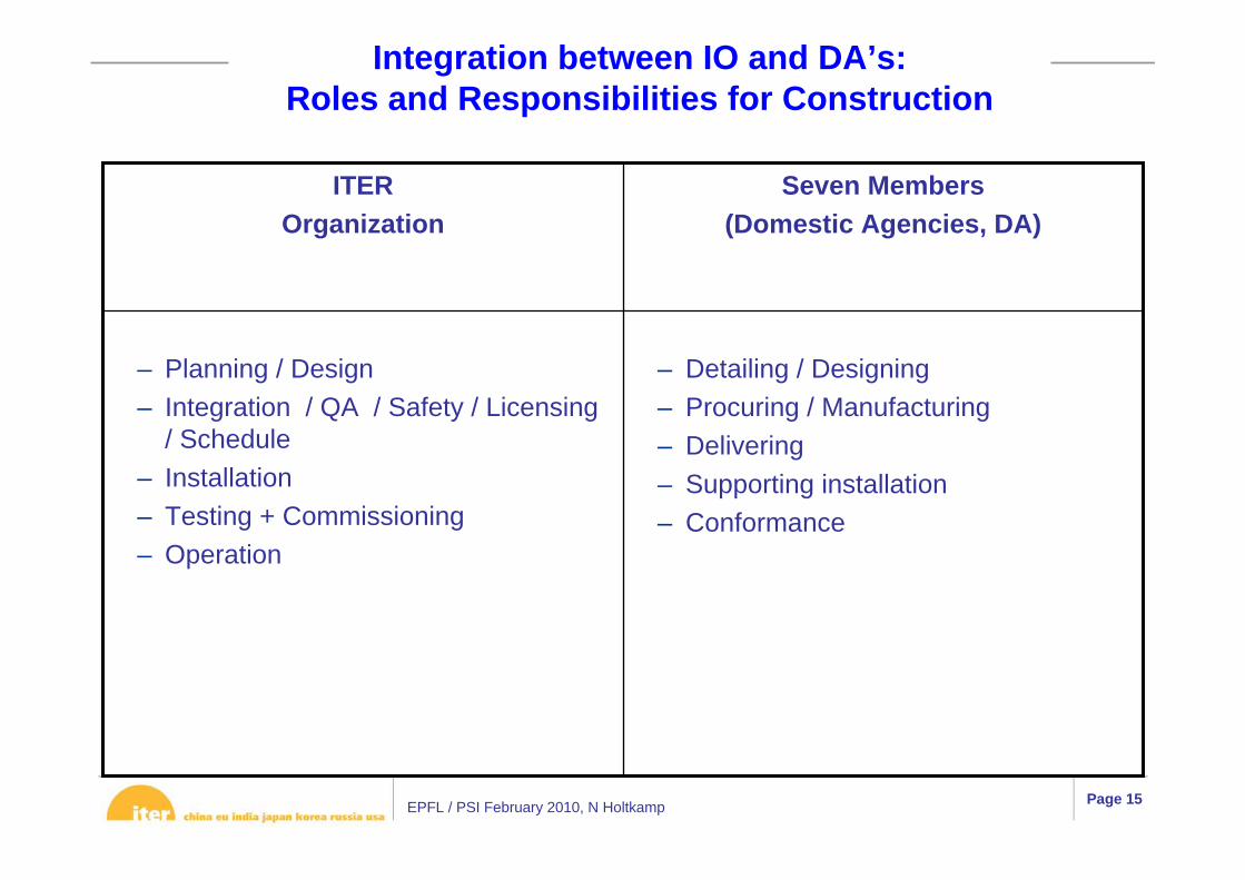
Integration between IO and DA’s:Roles and Responsibilities for Construction
– Detailing / Designing– Procuring / Manufacturing– Delivering– Supporting installation– Conformance
– Planning / Design – Integration / QA / Safety / Licensing
/ Schedule– Installation – Testing + Commissioning – Operation
Seven Members(Domestic Agencies, DA)
ITER Organization
EPFL / PSI February 2010, N Holtkamp Page 16
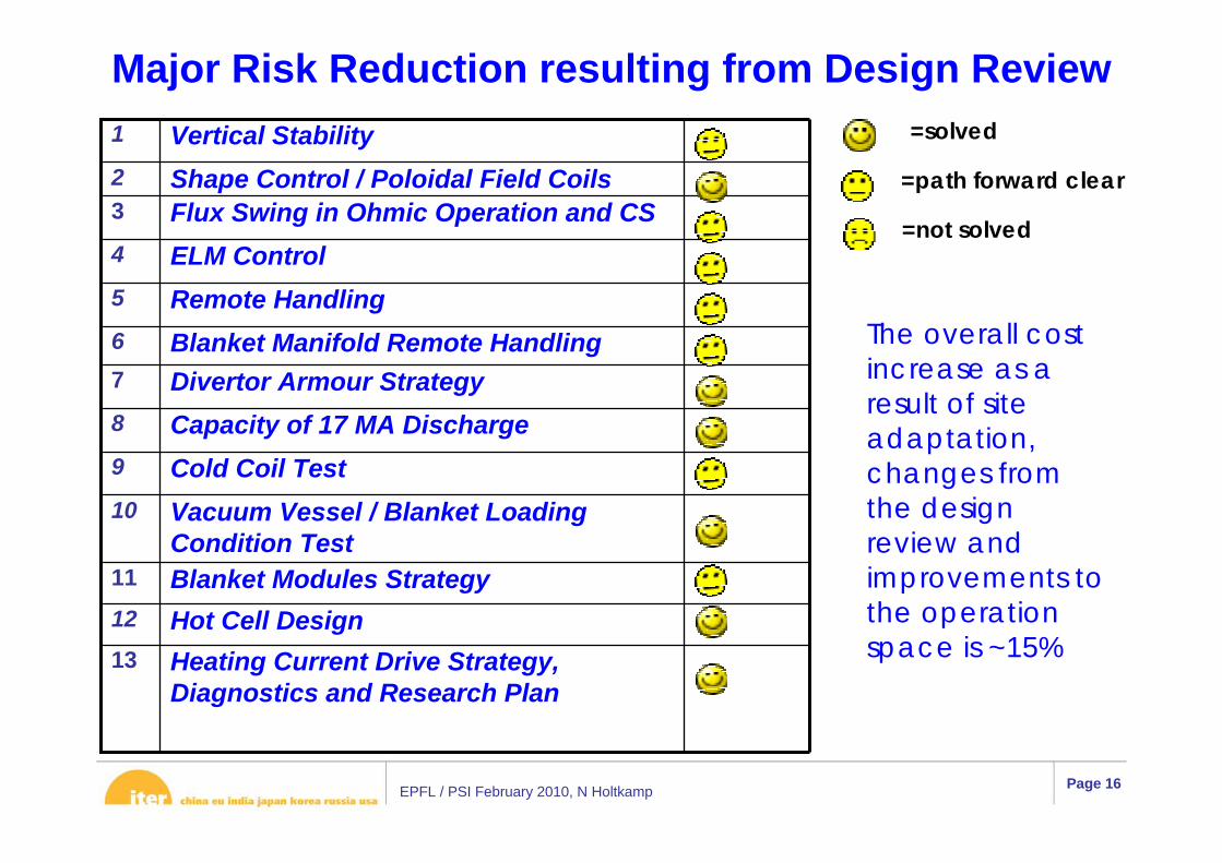
Major Risk Reduction resulting from Design Review
Heating Current Drive Strategy, Diagnostics and Research Plan
Hot Cell DesignBlanket Modules Strategy
Vacuum Vessel / Blanket Loading Condition Test
Cold Coil TestCapacity of 17 MA DischargeDivertor Armour StrategyBlanket Manifold Remote HandlingRemote HandlingELM ControlFlux Swing in Ohmic Operation and CSShape Control / Poloidal Field CoilsVertical Stability
13
12
11
10
9
8
76
5
4
32
1 =solved
=path forward clear
=not solved
The overall cost increase as a result of site adaptation, changes from the design review and improvements to the operation space is ~15%
EPFL / PSI February 2010, N Holtkamp Page 17
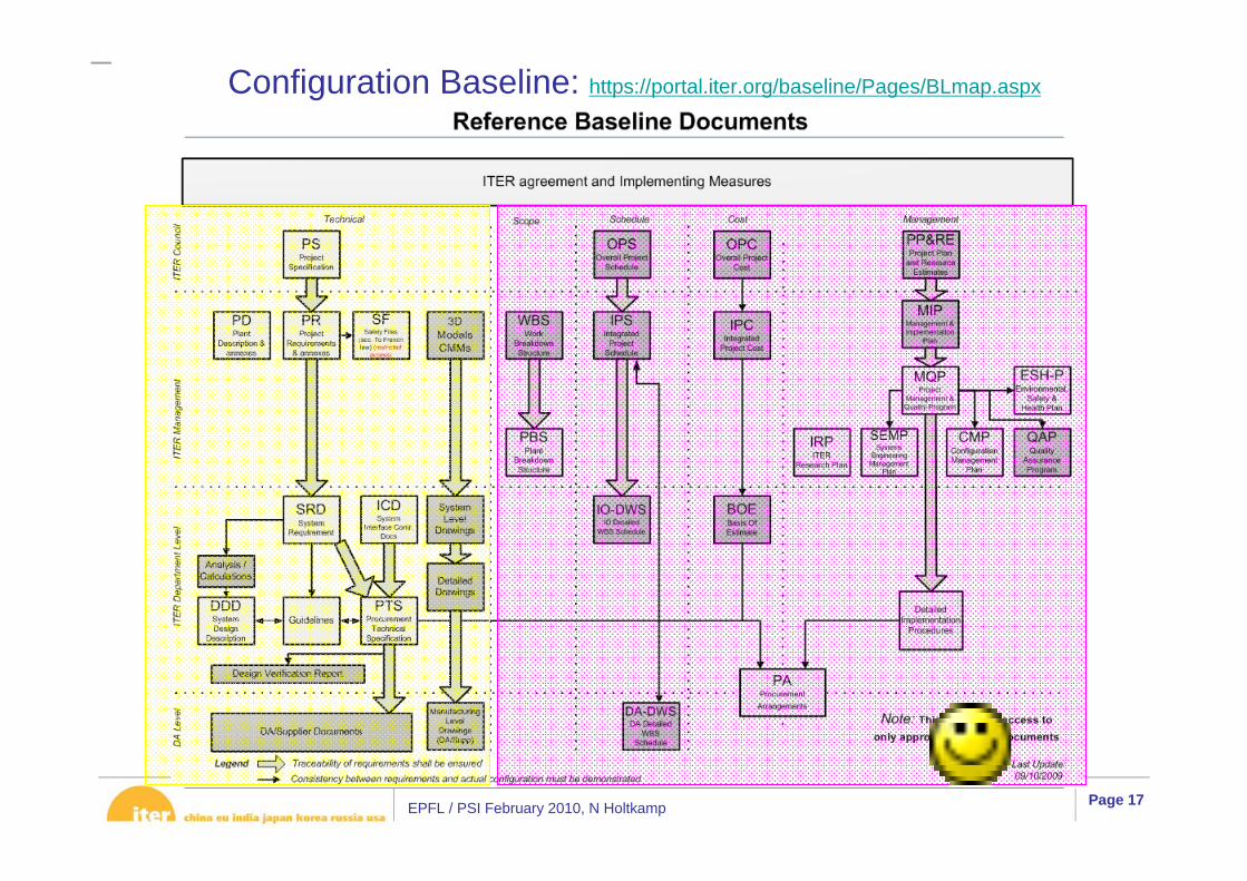
Configuration Baseline: https://portal.iter.org/baseline/Pages/BLmap.aspx
EPFL / PSI February 2010, N Holtkamp Page 18
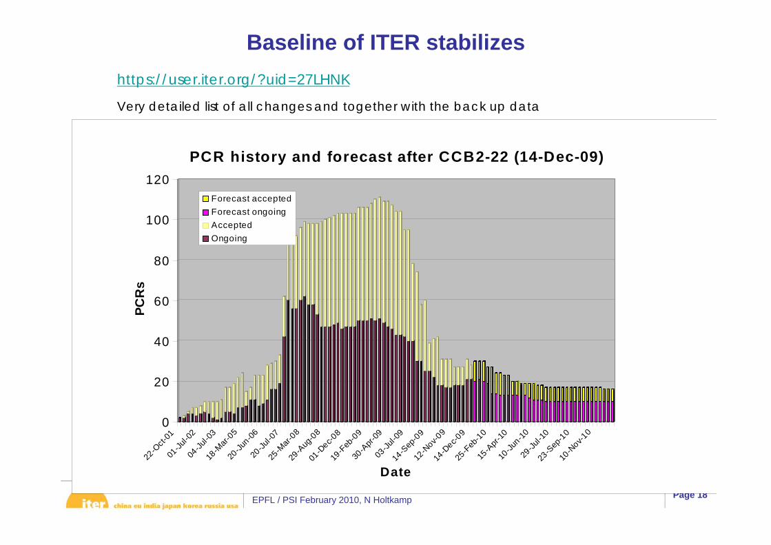
Baseline of ITER stabilizeshttps://user.iter.org/?uid=27LHNK
Very detailed list of all changes and together with the back up data
0
20
40
60
80
100
120
PCR
s
22-O
ct-01
01-Ju
l-02
04-Ju
l-03
18-M
ar-05
20-Ju
n-0620
-Jul-0
725
-Mar-
0829
-Aug
-08
01-D
ec-08
19-F
eb-0
930
-Apr-
0903
-Jul-0
914
-Sep
-09
12-N
ov-09
14-D
ec-09
25-F
eb-1
015
-Apr-
1010
-Jun-10
29-Ju
l-10
23-S
ep-1
010
-Nov-1
0
Date
PCR history and forecast after CCB2-22 (14-Dec-09)
Forecast acceptedForecast ongoingAcceptedOngoing
EPFL / PSI February 2010, N Holtkamp Page 19
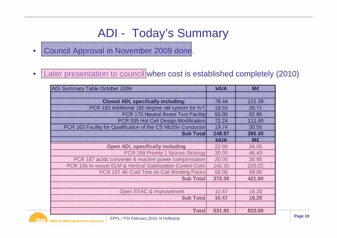
ADI - Today’s Summary• Council Approval in November 2009 done.
• Later presentation to council when cost is established completely (2010)
ADI Summary Table October 2009 kIUA M€
Closed ADI, specifcally including: 78.44 121.39PCR 183 Additional 180 degree rail system for IVT 18.55 28.71
PCR 170 Neutral Beam Test Facility 60.00 92.86PCR 035 Hot Cell Design Modification 72.24 111.80
PCR 163 Facility for Qualification of the CS Nb3Sn Conductor 19.74 30.55Sub Total 248.97 385.30
kIUA M€Open ADI, specifically including 22.00 34.05
PCR 199 Priority 1 Spares Strategy 30.00 46.43PCR 187 ac/dc converter & reactive power compensation 20.00 30.95
PCR 166 In vessel ELM & Vertical Stabilization Control Coils 142.30 220.22PCR 157 4K Cold Test on Coil Winding Packs 58.06 89.85
Sub Total 272.36 421.50
Open STAC & Improvement 10.47 16.20Sub Total 10.47 16.20
Total 531.80 823.00
EPFL / PSI February 2010, N Holtkamp Page 20
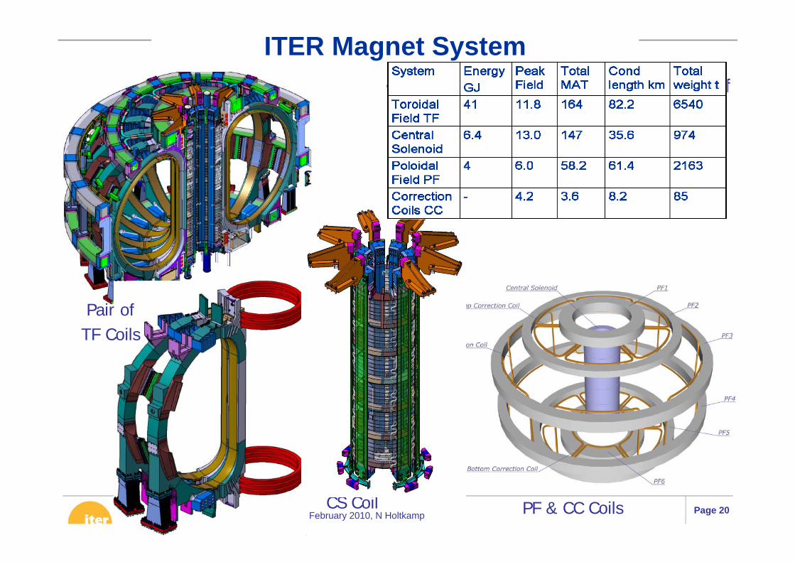
• The ITER magnet system is made up of− 18 Toroidal Field (TF) Coils,− a 6-module Central Solenoid (CS),− 6 Poloidal Field (PF) Coils,− 9 pairs of Correction Coils (CC).
Pair of TF Coils
PF & CC CoilsCS Coil
ITER Magnet System
EPFL / PSI February 2010, N Holtkamp Page 21
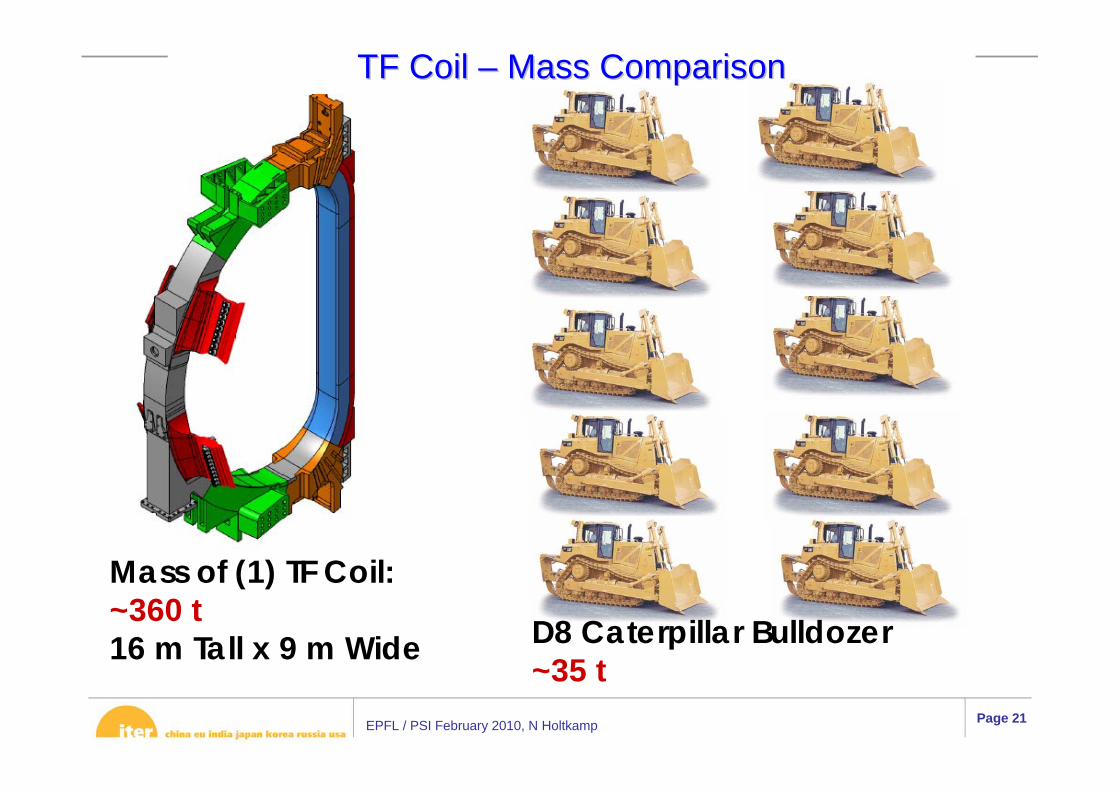
TF Coil TF Coil –– Mass ComparisonMass Comparison
Mass of (1) TF Coil:~360 t16 m Tall x 9 m Wide D8 Caterpillar Bulldozer
~35 t

EPFL / PSI February 2010, N Holtkamp Page 22
ITER Conductors
Cooling Spiral
• ITER coils are wound from Cable-In-Conduit Conductors (CICC’s), relying on superconducting multifilament composite strands mixed with pure Cu strands/cores.• The strands are assembled in amultistage rope-type cable around an open central cooling spiral.• The cable and its spiral are inserted inside a stainless steel conduit which provides helium confinement.
Stainless Steel Conduit
X-section of 70kA ITER TF Conductor (CEA)
Final-Stage Cable
(ASIPP)(NFRI)
EPFL / PSI February 2010, N Holtkamp Page 23
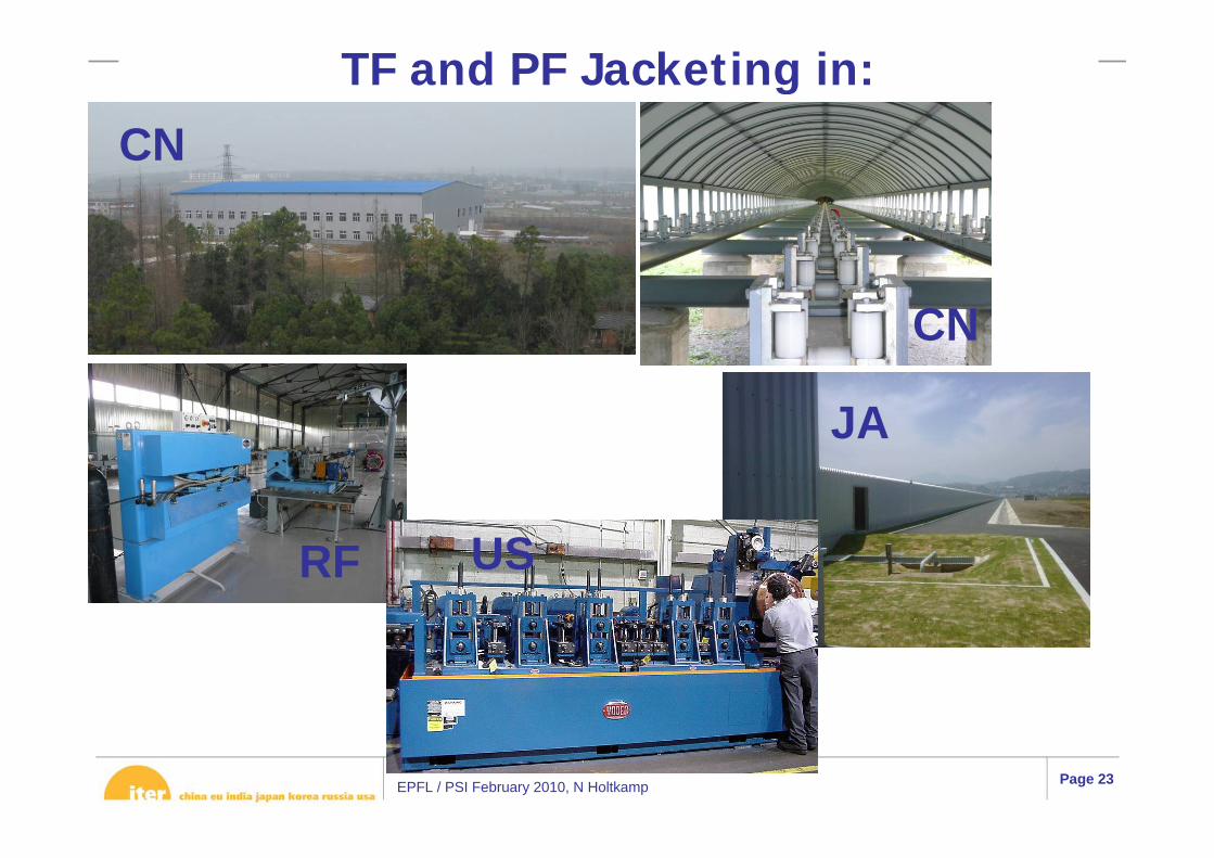
TF and PF Jacketing in:
CN
RF
JA
US
CN

EPFL / PSI February 2010, N Holtkamp Page 24
Vacuum Vessel Mass Comparison
VV & In-vessel components mass: ~8000 t19.4 m outside diameter x 11.3 m tall
Eiffel Tower mass: ~7300 t324 m tall
Europe is going out for tender this weekKorea has already selected the company

EPFL / PSI February 2010, N Holtkamp Page 25
Issues and Design studies for VVFour major issues remained after the design review
for the VV and were tackled in 2009
1. Insufficient shielding for TF coils at inner leg– Required 14 kW, without mitigation 23 kW
2. Electromagnetic loads on the blanket modules– Was factor 2 too high – reduced by slotting shield
module
3. Manufacturability of VV considering tight tolerances
– Some minor design changes after significant effort for studying also more drastic changes
4. Integration of the ELM and VS coils– 40 mm more space made available by 3-D shaping
of inner shell and thinning the VV at the outer leg

EPFL / PSI February 2010, N Holtkamp Page 26
Partial VV Mock-up: Curved (Left) and Straight (Right) Sections (EU)
R&D for the ITER VV and major Interfaces
Electron Beam welding on the inner shell
VV-interfaces with ELM coils, feeders, manifold, blanket
EPFL / PSI February 2010, N Holtkamp Page 27
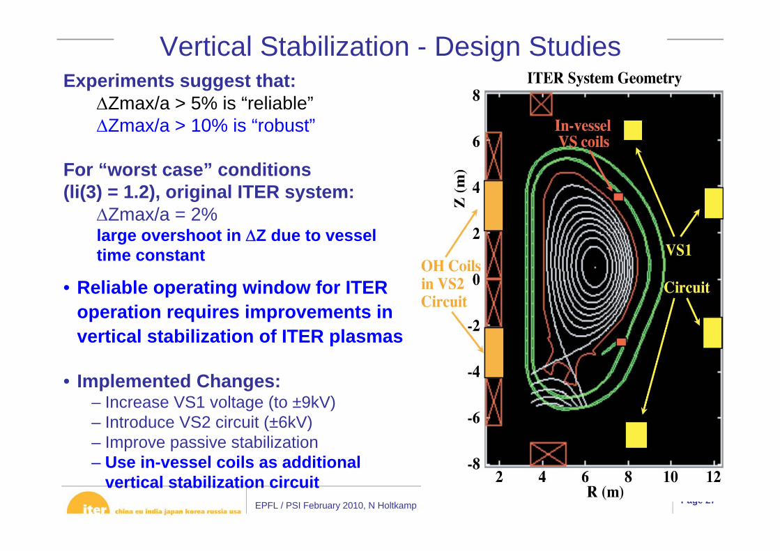
Vertical Stabilization - Design Studies
• Reliable operating window for ITER operation requires improvements in vertical stabilization of ITER plasmas
• Implemented Changes:– Increase VS1 voltage (to ±9kV)– Introduce VS2 circuit (±6kV)– Improve passive stabilization– Use in-vessel coils as additional
vertical stabilization circuit
Experiments suggest that:ΔZmax/a > 5% is “reliable”ΔZmax/a > 10% is “robust”
For “worst case” conditions(li(3) = 1.2), original ITER system:
ΔZmax/a = 2%large overshoot in ΔZ due to vessel time constant
EPFL / PSI February 2010, N Holtkamp Page 28
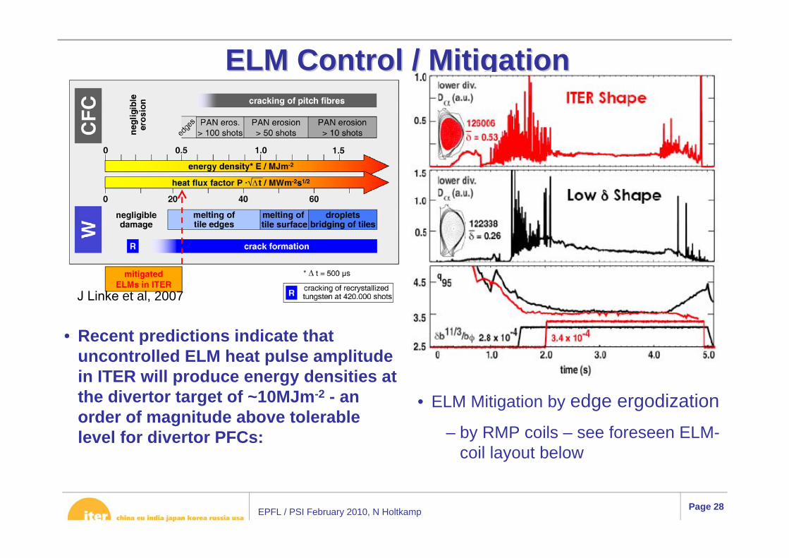
• Recent predictions indicate that uncontrolled ELM heat pulse amplitude in ITER will produce energy densities at the divertor target of ~10MJm-2 - an order of magnitude above tolerable level for divertor PFCs:
ELM Control / MitigationELM Control / Mitigation
J Linke et al, 2007
• ELM Mitigation by edge ergodization– by RMP coils – see foreseen ELM-
coil layout below
EPFL / PSI February 2010, N Holtkamp Page 29
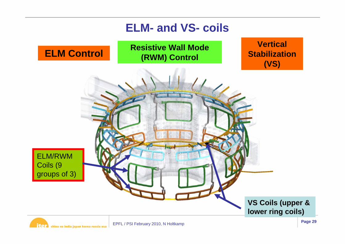
ELM- and VS- coilsVertical
Stabilization (VS)
ELM Control Resistive Wall Mode (RWM) Control
ELM/RWM Coils (9 groups of 3)
VS Coils (upper & lower ring coils)
EPFL / PSI February 2010, N Holtkamp Page 30
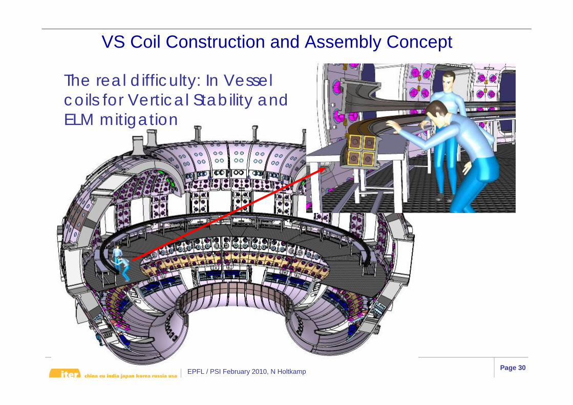
VS Coil Construction and Assembly Concept
The real difficulty: In Vessel coils for Vertical Stability and ELM mitigation
EPFL / PSI February 2010, N Holtkamp Page 31
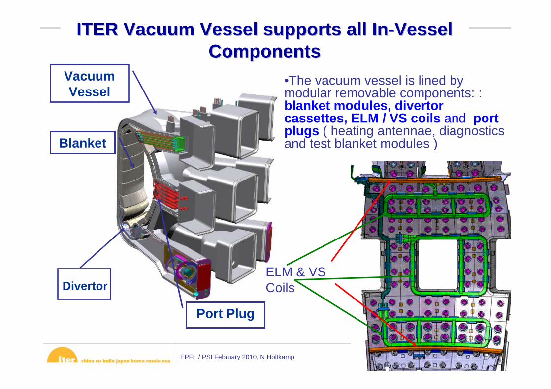
Vacuum Vessel
Blanket
Divertor
ITER Vacuum Vessel supports all InITER Vacuum Vessel supports all In--Vessel Vessel ComponentsComponents
•The vacuum vessel is lined by modular removable components: : blanket modules, divertor cassettes, ELM / VS coils and port plugs ( heating antennae, diagnostics and test blanket modules )
Port Plug
ELM & VS Coils

EPFL / PSI February 2010, N Holtkamp Page 32
Blanket System
Scope• 440 blanket modules at ~4 ton each• ~40 different blanket modules
Blanket system main functions :• Exhaust the majority of the fusion power• Reduce the nuclear responses in the vacuum vessel and superconducting coils
Challenge EM Forces, FW heatflux
FW shaped – avoid edges – 5 MW/m2 in 60% of areaSeparable FW module, shield module slotted to reduce EM forces
EPFL / PSI February 2010, N Holtkamp Page 33
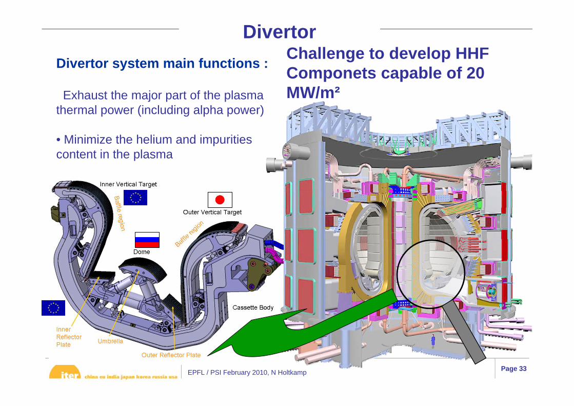
Divertor system main functions :
Exhaust the major part of the plasma thermal power (including alpha power)
• Minimize the helium and impurities content in the plasma
DivertorChallenge to develop HHF Componets capable of 20 MW/m²

EPFL / PSI February 2010, N Holtkamp Page 34
400 mm
Tungsten
CFC
A qualification is “…needed for the critical procurement packages shared by multi-Parties…”, including the divertor
Divertor Qualification Prototypes
All the 3 DAs have qualified to start procurement

EPFL / PSI February 2010, N Holtkamp Page 35
Overview of the EC system13
The EC system consists of:• Up to 13 High Voltage Power Supplies• Up to 26 Gyrotrons• 24 Transmission Lines• 1 Equatorial and 4 Upper Launchers
EPFL / PSI February 2010, N Holtkamp Page 36
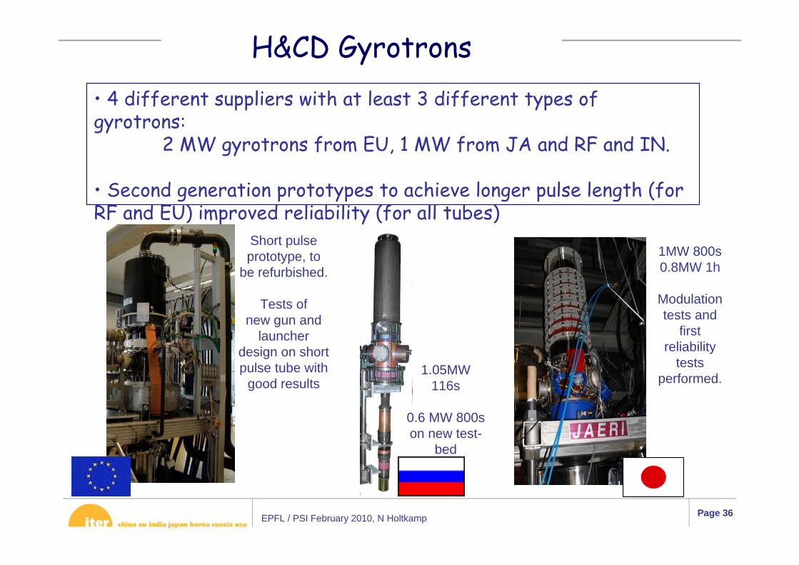
H&CD Gyrotrons• 4 different suppliers with at least 3 different types of gyrotrons:
2 MW gyrotrons from EU, 1 MW from JA and RF and IN.
• Second generation prototypes to achieve longer pulse length (forRF and EU) improved reliability (for all tubes)
Short pulse prototype, to
be refurbished.
Tests ofnew gun and
launcher design on short pulse tube with
good results1.05MW
116s
0.6 MW 800s on new test-
bed
1MW 800s0.8MW 1h
Modulation tests and
first reliability
tests performed.
EPFL / PSI February 2010, N Holtkamp Page 37
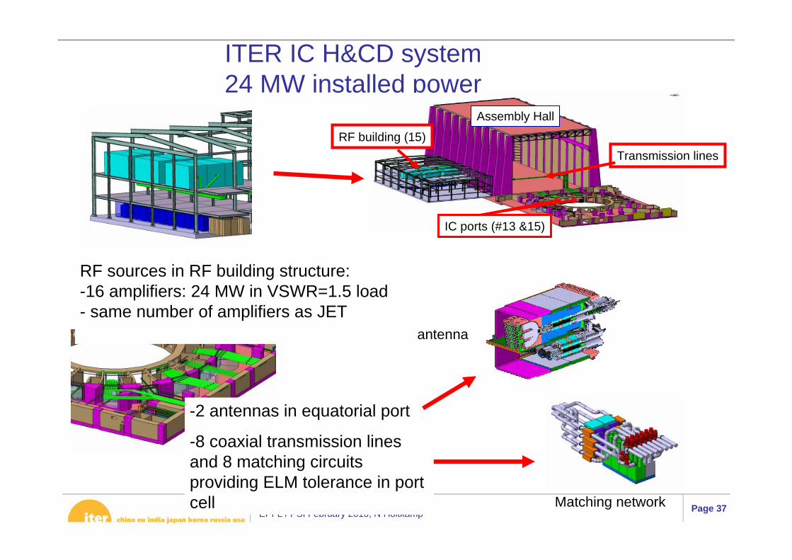
ITER IC H&CD system24 MW installed power
RF sources in RF building structure:-16 amplifiers: 24 MW in VSWR=1.5 load- same number of amplifiers as JET
-2 antennas in equatorial port
-8 coaxial transmission lines and 8 matching circuits providing ELM tolerance in port cell
RF building (15)
IC ports (#13 &15)
Assembly Hall
Transmission lines
antenna
Matching network

EPFL / PSI February 2010, N Holtkamp Page 38
Control room
MITICASPIDER
1 MV PSPRIMA (NBTF) Layout on the Padua site
25 m
EPFL / PSI February 2010, N Holtkamp Page 39
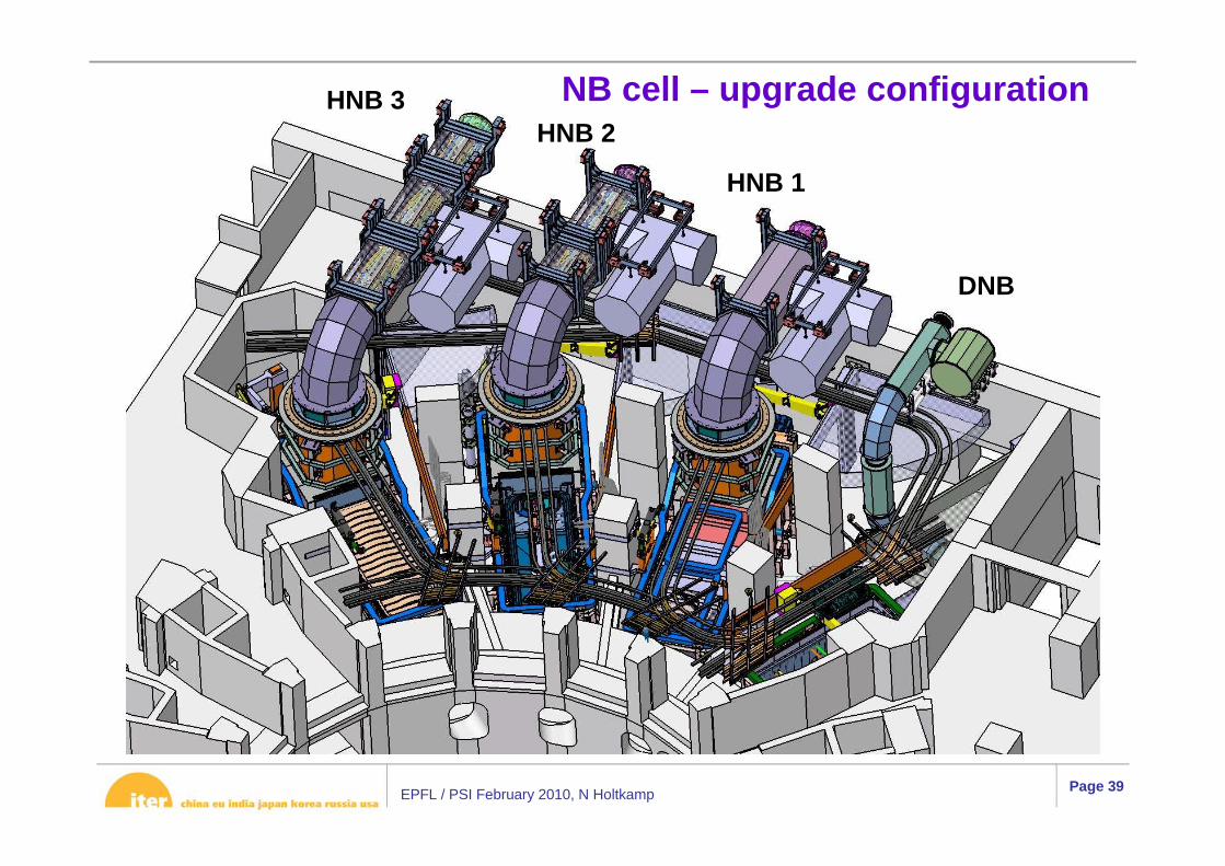
HNB 1
HNB 2HNB 3
DNB
NB cell – upgrade configuration

EPFL / PSI February 2010, N Holtkamp Page 40
1 MV bushing
Beam sourceNeutraliserResidual ion
dump
ACC coils
VVPSS box
Valve
Magnetic & radiation shield
Calorimeter
Cut-away view of an HNB injector
EPFL / PSI February 2010, N Holtkamp Page 41
2009 Achievements
• Finalized the preliminary design of all buildings through Jacobsengineering contract;
• Established good integration between F4E and IO on building construction team providing full support;
• Proposed and integrated common Annex Building approach between, France, EU and IO;
• Finalized the close out of all Vacuum Vessel design issues;• Implemented a major Value Engineering program, especially on
buildings, but also on all major components;• Established Integrated Project Teams (IPTs) for virtually all areas
of high integration;• Distributed the new work scope (coming from Design Review and
“missing items” among all DAs, maintaining the fair share;• Developed a new schedule with all DAs which substantially
reduces risk and flattens the manpower and cost profile;

EPFL / PSI February 2010, N Holtkamp Page 42
2009 Achievements and Directions• Achieved detailed integration and hand-off between the DAs and
IO on components as part of Integrated Project Schedule development;
• Excellent progress on licensing with RPrS ready to go in February 2010 consistent with building construction start;
• Presented a full and consistent set of Baseline documents to: Management Assessor, Briscoe Review, Systems Integration Review, STAC and MAC. (>148 reviewers between Sept to November)
• The HOD in April and the Council in June, agreed on a Dec 2018 “First Plasma” date and the concept of phased commissioning, but in November, while a complete baseline was established, new direction on further developing the schedule with reduced risk was given.
• The IO reduced the 2008 resource estimate (1550) already by 200M€ and IC expects us to cut by another 10% (~200M€).

EPFL / PSI February 2010, N Holtkamp Page 43
The ITER Baseline: Scope-Schedule-Cost
• Original Agreement was made on the basis of the 2001 Baseline design;
• In 2006 at IIC-1 all Members encouraged the IO to execute a Design Review as soon as possible;
• The ITER Design Review process started in December 2006 as an in-house activity with the involvement of more than 150 experts from the Members; It resulted in approximately 80 design changes as necessary, of which only a few have a major impact, e.g. cold test of the magnets, NBTF etc.
• STAC-2 in Nov. 2007 reviewed the results of Design Review and furtheridentified 13 issues, such as ELM control, vertical stability etc. In May of 2008 STAC supported the IO proposal to incorporate design changes into the 2007 Baseline design; - As a result, the Project Specifications was approved by IC-2 in June 2008.
• Consistent with this scope and within the boundary conditions set by IC-4, IO has prepared an Integrated Project Schedule and a Cost estimate which forms a consistent set of documents.

EPFL / PSI February 2010, N Holtkamp Page 44
20092009 20102010 20112011 20122012 20132013 20142014 20152015 20162016 20172017 20182018 20192019 20202020
Issue VV Issue VV PAsPAs 11stst VV Sector at Site LastVV Sector at Site Last VV Sector at SiteVV Sector at Site
Issue PF Coil Issue PF Coil PAsPAs 11stst PF Coil at Site PF Coil at Site Last PF Coil at SiteLast PF Coil at Site
First PlasmaFirst Plasma
TokamakTokamak Basic MachineBasic Machine
ITER ConstructionITER Construction
Issue TF Coils Issue TF Coils PAsPAs 11stst TF Coil at Site TF Coil at Site Last TF Coil at SiteLast TF Coil at Site
Buildings & SiteBuildings & Site
TokamakTokamak Complex ExcavationsComplex Excavations
TokamakTokamak Building ConstructionBuilding Construction
Site Leveling & Pre Excavation *Site Leveling & Pre Excavation *
TokamakTokamak Bldg 11 RFEBldg 11 RFE
TokamakTokamak AssemblyAssembly
TokamakTokamak Basic Machine AssemblyBasic Machine Assembly
Ex Vessel AssemblyEx Vessel Assembly
In Vessel AssemblyIn Vessel Assembly
Start Install CS Start Cryostat ClosureStart Install CS Start Cryostat Closure
Pump Down & Integrated CommissioningPump Down & Integrated Commissioning
Start Sub Assemble VVStart Sub Assemble VV
Seismic Isolation Seismic Isolation BasematBasemat
20212021 20222022
Remaining ConstructionRemaining Construction
ITER OperationsITER Operations
Assembly Phase 2Assembly Phase 2
Assembly Phase 3Assembly Phase 3
Plasma OperationsPlasma Operations
Issue Construction PAIssue Construction PAConstruction ContractConstruction ContractAE Contract & DesignAE Contract & Design
* Site Leveling was completed in June 09* Site Leveling was completed in June 09
Updated Schedule
EPFL / PSI February 2010, N Holtkamp Page 45
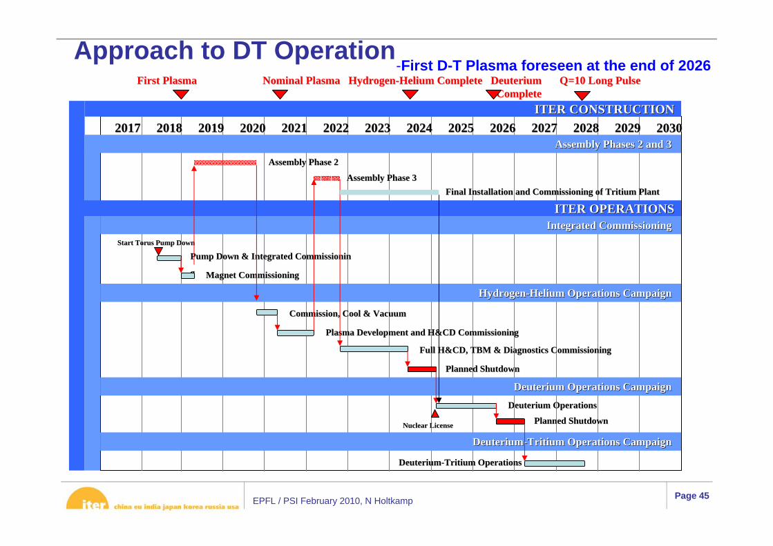
First PlasmaFirst Plasma
ITER CONSTRUCTIONITER CONSTRUCTION
Q=10 Long PulseQ=10 Long Pulse
20172017 20182018 20192019 20202020 20212021 20222022 20232023 20242024 20252025 20262026 20272027 20282028 20292029 20302030
Start Torus Pump DownStart Torus Pump Down
Pump Down & Integrated Pump Down & Integrated CommissioninCommissionin
gg
Plasma Development and H&CD CommissioningPlasma Development and H&CD Commissioning
Magnet CommissioningMagnet Commissioning
Commission, Cool & VacuumCommission, Cool & Vacuum
Full H&CD, TBM & Diagnostics CommissioningFull H&CD, TBM & Diagnostics Commissioning
Assembly Phases 2 and 3 Assembly Phases 2 and 3 Assembly Phase 2Assembly Phase 2
Assembly Phase 3Assembly Phase 3
Integrated Commissioning Integrated Commissioning ITER OPERATIONSITER OPERATIONS
Nominal Plasma HydrogenNominal Plasma Hydrogen--Helium Complete Deuterium Helium Complete Deuterium CompleteComplete
HydrogenHydrogen--Helium Operations Campaign Helium Operations Campaign
Deuterium Operations Campaign Deuterium Operations Campaign
Planned ShutdownPlanned Shutdown
Planned ShutdownPlanned Shutdown
DeuteriumDeuterium--Tritium Operations Campaign Tritium Operations Campaign
Deuterium OperationsDeuterium Operations
DeuteriumDeuterium--Tritium OperationsTritium Operations
Nuclear LicenseNuclear License
Final Installation and Commissioning of Tritium PlantFinal Installation and Commissioning of Tritium Plant
Approach to DT Operation-First D-T Plasma foreseen at the end of 2026
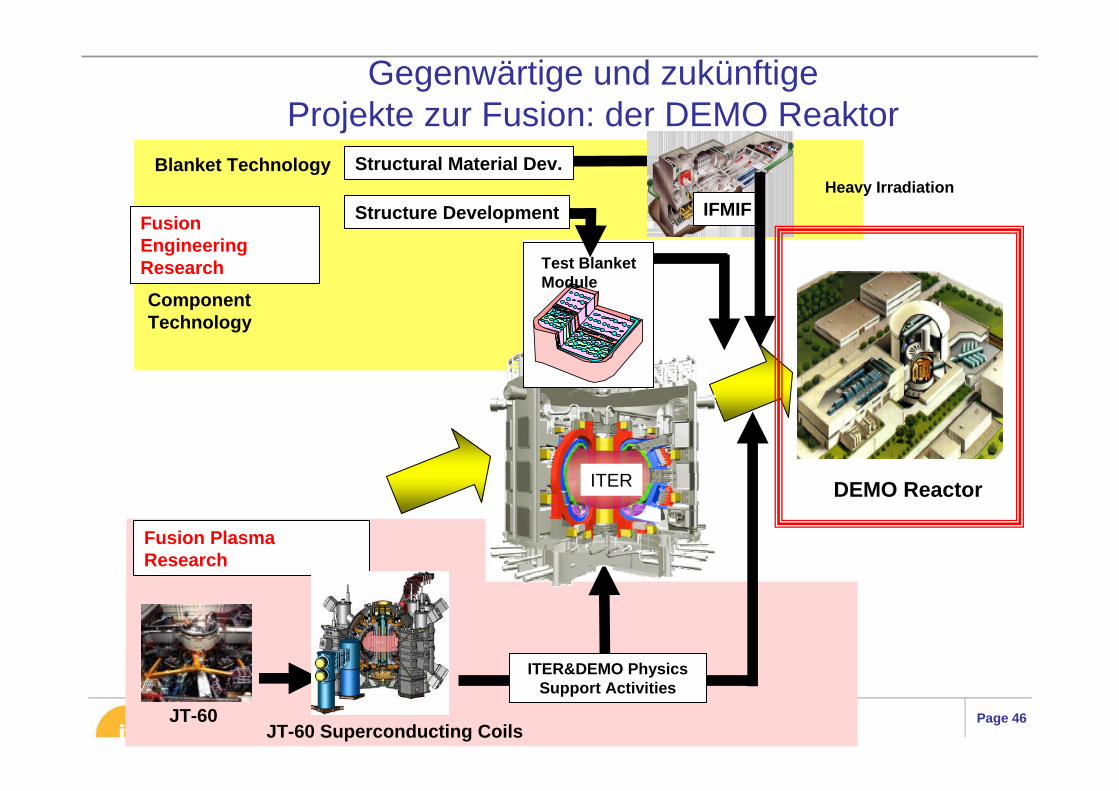
EPFL / PSI February 2010, N Holtkamp Page 46JT-60
Fusion Plasma Research
DEMO ReactorITER
ITER&DEMO Physics Support Activities
Component Technology
Test Blanket Module
Blanket TechnologyHeavy Irradiation
IFMIFStructure Development
Structural Material Dev.
Fusion Engineering Research
JT-60 Superconducting Coils
Gegenwärtige und zukünftigeProjekte zur Fusion: der DEMO Reaktor
EPFL / PSI February 2010, N Holtkamp Page 47
00 05 10 15 20 25 30 40 45
Operationupgrade,construction
Today’sexpts.
ITER
IFMIF
DEMO
CommercialPower Plants
ConstructionH
2nd DT Op. PhaseDTD
Test/Optimise Blanket
Construction Qualify DEMO Materials Optimise MaterialsDesign
Design Construction Initial Operation Reliability demo
Concept Design Construction Op.
Des.
AlternativeConfinementSchemes
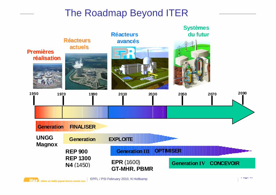
The Roadmap Beyond ITER
Generation
Generation
1950 1970 1990 2010 2030 2050 2070 2090
Generation III
PPrreemmiièèrreess rrééaalliissaattiioonnss
UNGG Magnox
RRééaacctteeuurrss aaccttuueellss
REP 900 REP 1300 N4 (1450) EPR (1600)
GT-MHR, PBMR
RRééaacctteeuurrss aavvaannccééss
SSyyssttèèmmeess dduu ffuuttuurr
Generation IV
FINALISER
EXPLOITE
OPTIMISER
CONCEVOIR

EPFL / PSI February 2010, N Holtkamp Page 48
ITER – a Global Challenge
• „The stakes are considerable, not to say vital for our planet.“Manuel Barroso, President of the European Commission

EPFL / PSI February 2010, N Holtkamp Page 49
• A new Baseline has been fully established but not fully agreed upon yet– Technical Baseline– Detailed schedule – resource loaded– The ITER value including all the design improvements and the IO cost
• The licensing process is not impinging on construction and going well…
• The IO together with the DAs is not only starting procurement but also closes out remaining design issues or consequent changes from the design review
• A realistic RH – Hot Cell concept and design exists today which also allowed to obtain a correct value for the Hot Cell (part of ADI)
ITER is the key step towards the realization of fusion energy
with magnetic confinement
Conclusions

EPFL / PSI February 2010, N Holtkamp Page 50
Backup Material
EPFL / PSI February 2010, N Holtkamp Page 51
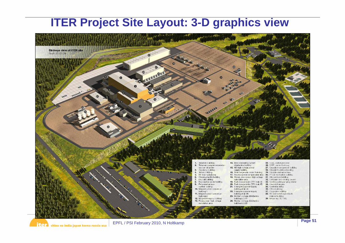
ITER Project Site Layout: 3-D graphics view
EPFL / PSI February 2010, N Holtkamp Page 521
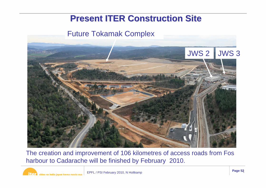
PresentPresent ITER Construction Site ITER Construction Site
JWS 2 JWS 3
The creation and improvement of 106 kilometres of access roads from Fosharbour to Cadarache will be finished by February 2010.
Future Tokamak Complex

EPFL / PSI February 2010, N Holtkamp Page 53
Progress of Procurement in kind
To date the following Procurement Arrangements (PAs) have been signed (value: 964 kIUA –> > 1500 MEuro):
• 6 PAs for the TF conductor (JA, EU, RF, KO,CN, US)• 2 PAs for TF magnet winding (EU, JA)• 1 PA for TF magnet structure (JA)• 3 PAs for the PF conductor (CN, EU, RF)• 1 PA for PF coil winding Building (EU)• 1 PA for PF magnets (2,3,4,5,6) –> (EU)• 4 PAs for VV (3 sectors), all ports, in wall shielding (KO, RF, IN)• 2 PAs for Divertor Dome and Outer Vertical Target (RF, JA)• 2 PAs for Architect engineering services, tokamak pit excavation, seismic
isolation pads (EU)• 2 PAs for power supplies of HNBI and DNBI (EU, IN)• 1 PA for Tokamak cooling water system (US)• 1 PA for machine assembly tooling (KO)In addition 14 PAs to be signed until end 2009 – value: 388 kIUA

EPFL / PSI February 2010, N Holtkamp Page 54
• The agreement ratified in 2007 foresaw a First Plasma and construction complete with all subsystems and components installed within 10 years of construction begin. It was assumed to be 2016.
• In June 2008, after the Design Review, IO presented to the Council an IPS which foresaw First Plasma in 2018 and beginning of DT operation in 2026; In addition a significant increase in resources was indicated.
• However, the design effort to finalize the procurement arrangements was underestimated and they were delayed as a result; analysis showed that First Plasma would be delayed to 2021 without management action
• In order to maintain the date 2018, IO proposed an Updated Schedule with a different approach to assembly, which allows ITER to achieve a First Plasma operation in 2018 (Ip ~ 100kA, tplasma ~ 100ms, Paux = 0 (except for ECRH breakdown power), BTF = 80%, BPF = 50%, BCS = 50%).
• Within this Updated Schedule, a construction and assembly sequence is proposed in which reduction of risk and cost to the project and maintaining D-T operation in 2026 are the key drivers.
Schedule
EPFL / PSI February 2010, N Holtkamp Page 55
Current status (October 2009)• All RPrS chapters and Impact Study are in first draft
– Some require completion with the outcome of safety analyses in progress, or design information from baseline documents to be fixed
• Many annexe documents completed– Translation into French under way
• Reviews of RPrS to be held October – December, by technical ROs, Safety Control Division (“second level” check), and in review including external experts - English version to be finalized by end of 2009
• Translation in French and final checking– Submission expected end of February 2010
• Should lead to issue of decree allowing “creation” of facility.– Further processes will follow to obtain authorisation for commissioning and
start-up.

EPFL / PSI February 2010, N Holtkamp Page 56
Feeders (31)(NbTi)
Correction Coils (18)(NbTi)
Poloidal Field Coils (6)(NbTi)
Toroidal Field Coils (18)(Nb3Sn)
Central Solenoid (6)(Nb3Sn)
Divertor (54 cassettes)
Blanket (440 modules)
Cryostat (29 m high x 28 m dia.)
Vacuum Vessel (9 sectors)
Thermal Shield (4 sub-assemblies)
In-Vessel Coils(2-VS & 27-ELM)
Status of ITER’s technical progress (highlights)Fusion gain Q = 10, Fusion Power: ~500MW, Ohmic burn 300 to 500 sec
Goal Q=5 for 3000 sec

EPFL / PSI February 2010, N Holtkamp Page 57
Physics driven Facility Improvementssee also design review above
• Significant improvement in ITER operational flexibility as result of Design Review:
– shape control and vertical stabilization– in-vessel RMP coils (ELM control, RWM control)– toroidal field ripple: converge on δTF,separatrix ~ 0.6-0.7%
⇒ low value of δTF,separatrix over range 2.65T ≤ B ≤ 5.3T– fuelling throughput: increased to 200 Pam3s-1 (ELM control)– H&CD: NBI shine-through armour, second ICRH antenna, ECRH
transmission line hardening to 2MW, H&CD testing facilities– Diagnostics: rebaselining, eg improved DT capability, tritium
retention,dust production– divertor configuration: improved equilibrium flexibility, extended
tungsten baffle– shielding blanket/ first wall: redesign in progress - improved operational
capability
EPFL / PSI February 2010, N Holtkamp Page 58
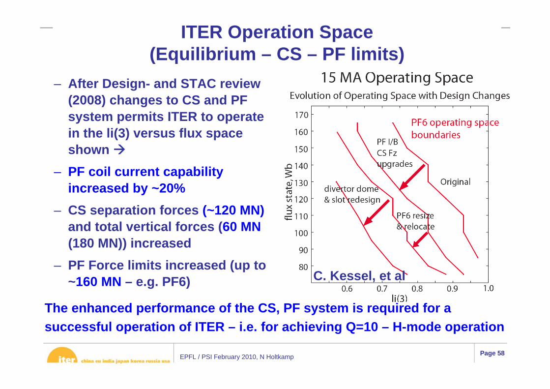
– After Design- and STAC review (2008) changes to CS and PF system permits ITER to operate in the li(3) versus flux space shown
– PF coil current capability increased by ~20%
– CS separation forces (~120 MN)and total vertical forces (60 MN(180 MN)) increased
– PF Force limits increased (up to ~160 MN – e.g. PF6)
ITER Operation Space (Equilibrium – CS – PF limits)
The enhanced performance of the CS, PF system is required for a successful operation of ITER – i.e. for achieving Q=10 – H-mode operation
C. Kessel, et al
EPFL / PSI February 2010, N Holtkamp Page 59
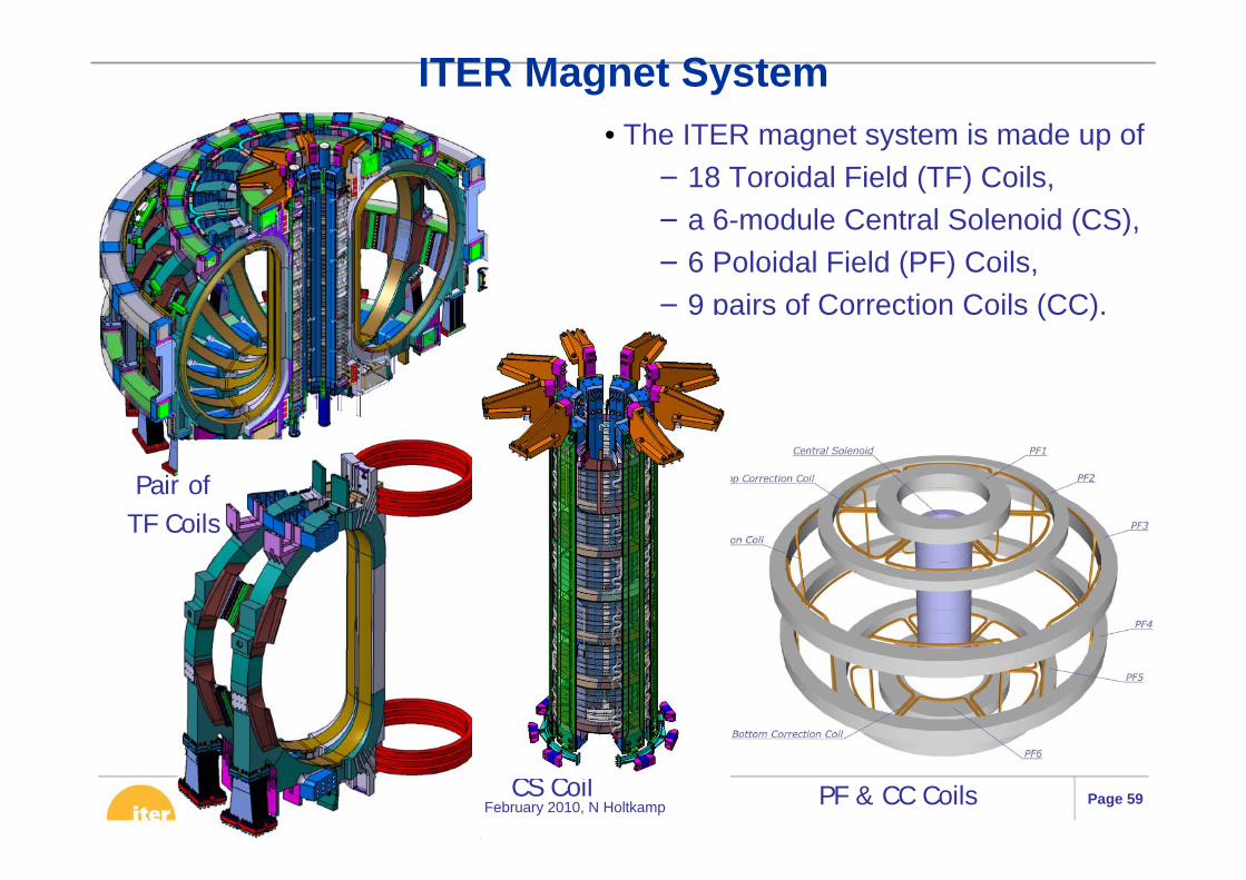
• The ITER magnet system is made up of− 18 Toroidal Field (TF) Coils,− a 6-module Central Solenoid (CS),− 6 Poloidal Field (PF) Coils,− 9 pairs of Correction Coils (CC).
Pair of TF Coils
PF & CC CoilsCS Coil
ITER Magnet System
EPFL / PSI February 2010, N Holtkamp Page 60
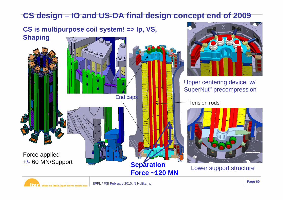
CS design – IO and US-DA final design concept end of 2009
Upper centering device w/SuperNut® precompression
Lower support structure
Tension rodsEnd caps
Force applied +/- 60 MN/Support Separation
Force ~120 MN
CS is multipurpose coil system! => Ip, VS, Shaping

EPFL / PSI February 2010, N Holtkamp Page 61
– One-dimensional modelling of the plasma core:
– Two dimensional modelling of the SOL and Divertor
– Physics based empirical model for the Pedestal
– Turbulence fluid model for the core
• Multimode – Lehigh –University - Bethman
ITER Operation Space (Fusion Performance) in H-mode predicted by an Integrated Plasma ModelG. Pacher, H. Pacher, Y. Igitkhanov, M. Sugihara, G. Janeschitz
Operational and objective limits:Q=5, LH transition, low temperature limit on alpha power, auxiliary power, edge density limit
EPFL / PSI February 2010, N Holtkamp Page 62
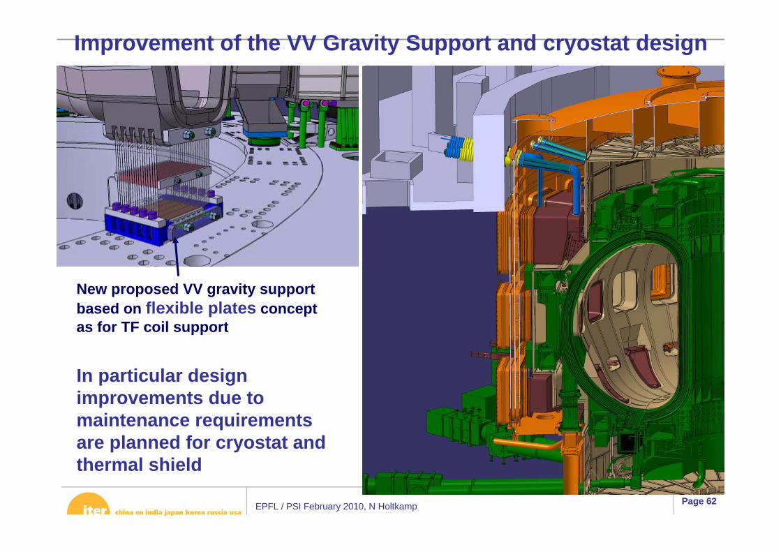
Improvement of the VV Gravity Support and cryostat design
New proposed VV gravity supportbased on flexible plates concept as for TF coil support
In particular design improvements due to maintenance requirements are planned for cryostat and thermal shield
EPFL / PSI February 2010, N Holtkamp Page 63
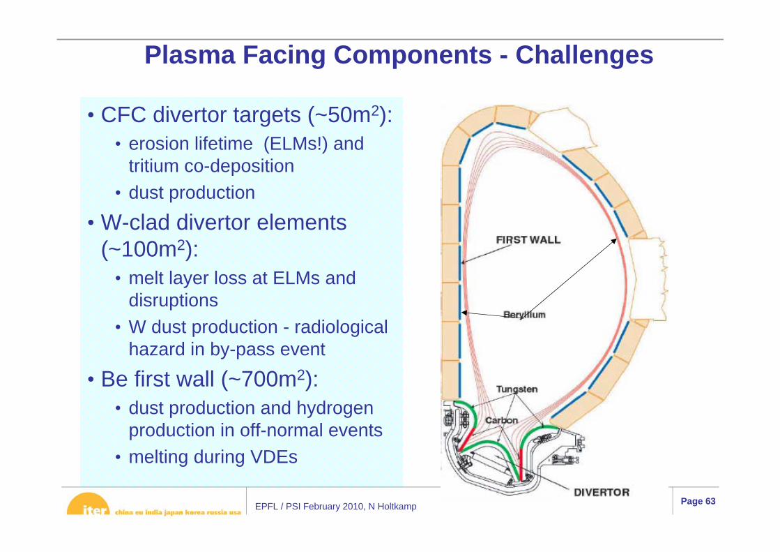
• CFC divertor targets (~50m2):• erosion lifetime (ELMs!) and
tritium co-deposition• dust production
• W-clad divertor elements (~100m2):
• melt layer loss at ELMs and disruptions
• W dust production - radiological hazard in by-pass event
• Be first wall (~700m2):• dust production and hydrogen
production in off-normal events• melting during VDEs
Plasma Facing Components - Challenges

EPFL / PSI February 2010, N Holtkamp Page 64
Blanket System
Scope• 440 blanket modules at ~4 ton each• ~40 different blanket modules
Blanket system main functions :• Exhaust the majority of the fusion power• Reduce the nuclear responses in the vacuum vessel and superconducting coils
Challenge EM Forces, FW heatflux
FW shaped – avoid edges – 5 MW/m2 in 60% of areaSeparable FW module, shield module slotted to reduce EM forces
EPFL / PSI February 2010, N Holtkamp Page 65
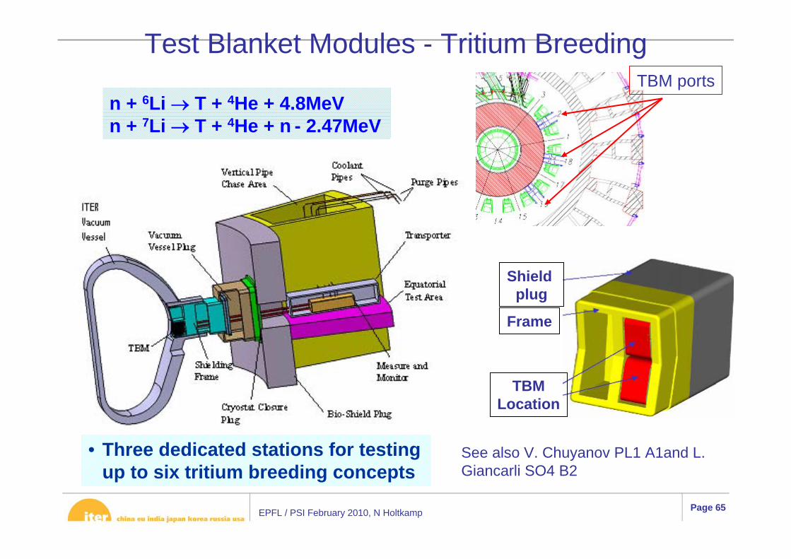
Shield plug
Frame
TBMLocation
TBM
TBM portsn + 6Li → T + 4He + 4.8MeVn + 7Li → T + 4He + n - 2.47MeV
• Three dedicated stations for testing up to six tritium breeding concepts
Test Blanket Modules - Tritium Breeding
See also V. Chuyanov PL1 A1and L. Giancarli SO4 B2
EPFL / PSI February 2010, N Holtkamp Page 66
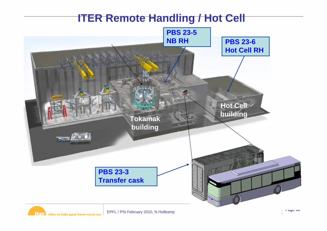
Tokamakbuilding
Hot Cellbuilding
ITER Remote Handling / Hot Cell
PBS 23-3Transfer cask
PBS 23-6Hot Cell RH
PBS 23-5NB RH

EPFL / PSI February 2010, N Holtkamp Page 67
Module / Tool transporter
Tractor
Cable Handling Equipment
Transfer frame for Cable Handling Equipment
Rail Support Equipment
Rail
Vehicle Manipulator
Blanket RH SystemRail Support Equipment and Module Transporter

EPFL / PSI February 2010, N Holtkamp Page 68
Full scale 180° rail deployment test (1998)
In-port rail connection2008-2009
2 decades of development to provide demonstration of feasibility and reliability
RH system for blanket has shown its ability to perform the job
Some issues remain
EPFL / PSI February 2010, N Holtkamp Page 69
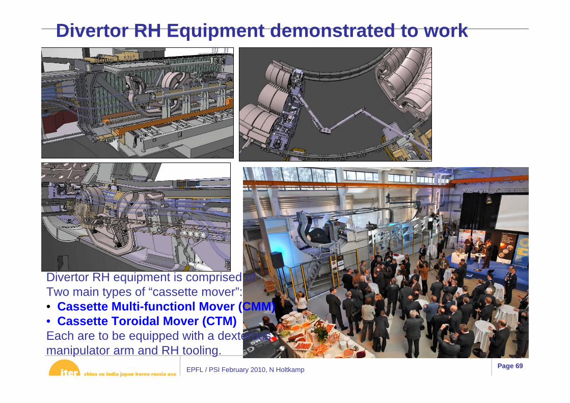
Divertor RH Equipment demonstrated to work
Divertor RH equipment is comprised ofTwo main types of “cassette mover”:• Cassette Multi-functionl Mover (CMM)• Cassette Toroidal Mover (CTM)Each are to be equipped with a dexterous manipulator arm and RH tooling.

EPFL / PSI February 2010, N Holtkamp Page 70
Cask Docking
refurbishment & test
Hot Cell designThe HC RH system will have the following equipment:
· Boom-style RH transporter(s)· Jib cranes transporters· Lifting jigs· Dexterous telemanipulators) end effectors· Direct viewing telemanipulators· Inspection equipment (including weld NDT, visual inspection, metrology)· Cleaning equipment (Vacuum cleaner). See also M
Benchikhoune SO4 A5
Hot- RH Test facility

EPFL / PSI February 2010, N Holtkamp Page 71
High Voltage Power Supplies
• Adaptable to 3 gyrotron types.
• 1 main Power Supply shared by 2 gyrotrons.
• Provides modulation for physics requirements.
• Existing PSM technology.• Design based on equivalent system, already installed on existing W7-X system.

EPFL / PSI February 2010, N Holtkamp Page 72
Schematic Transmission Line
• Evacuated HE11 waveguides with average length ~160m.• Rated for 2 MW CWoperation – nearly all components commercially available.• Collaboration on high power long pulse tests going on between US industry and JAEA.
56 TL on the launcher side
Up to 24 TL on the gyrotron
sideAverage length ~160
m

EPFL / PSI February 2010, N Holtkamp Page 73
EC Launchers
Equatorial launcher: Central heating & current drive• 1 port with 24 entries. • 3 steering mirrors in toroidal direction (0<ρT<0.45).
Upper launcher: Control of MHD activity• 4 ports with 32 entries in total. • 2 steering mirrors in poloidal direction (0.3<ρT<0.95).
• Both at or beyond preliminary design, no show stoppers in design, final design 2013.• Prototype tests on critical components are on going (steering mechanism, BSM, sections of port plug structure.

EPFL / PSI February 2010, N Holtkamp Page 74
ICH&CD system
Scope: Provide 20 MW of plasma heating during any phase of the discharge in differeconditions (Second harmonic tritium, 3He minority heating, D minority heating):
–Flexibility : •40 to 55 MHz corresponding to 3 main scenarios,•full control of phasing of the antenna to access current drive configuration•100% power modulation•Compatible with lower magnetic field if needed (to be checked for lower side of Freq. Band)
–Constraints : coupling is dependant of plasma configuration (geometry, density, shape, composition,ELMs, etc…)
Upgrade possible by doubling the equipment to 40 MW
System is composed of:
– AC/DC power supply system, IN (no R&D)– DC/RF converters system, IN (no R&D)– Transmission line system, US (little R&D)– Antenna system EU (lot of R&D)+ control system interfaced with Tokamak IO
EPFL / PSI February 2010, N Holtkamp Page 75
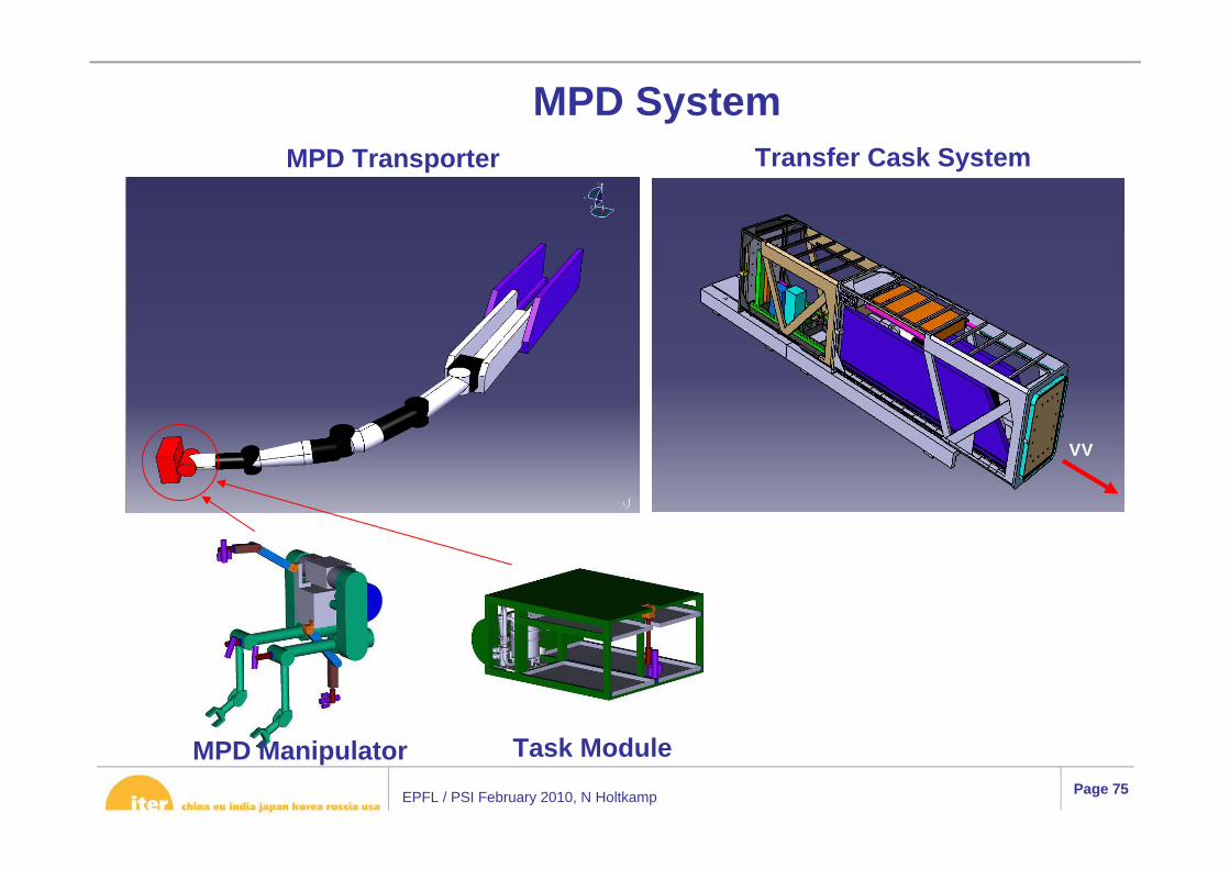
MPD Manipulator Task Module
MPD Transporter Transfer Cask System
MPD System
VV
EPFL / PSI February 2010, N Holtkamp Page 76
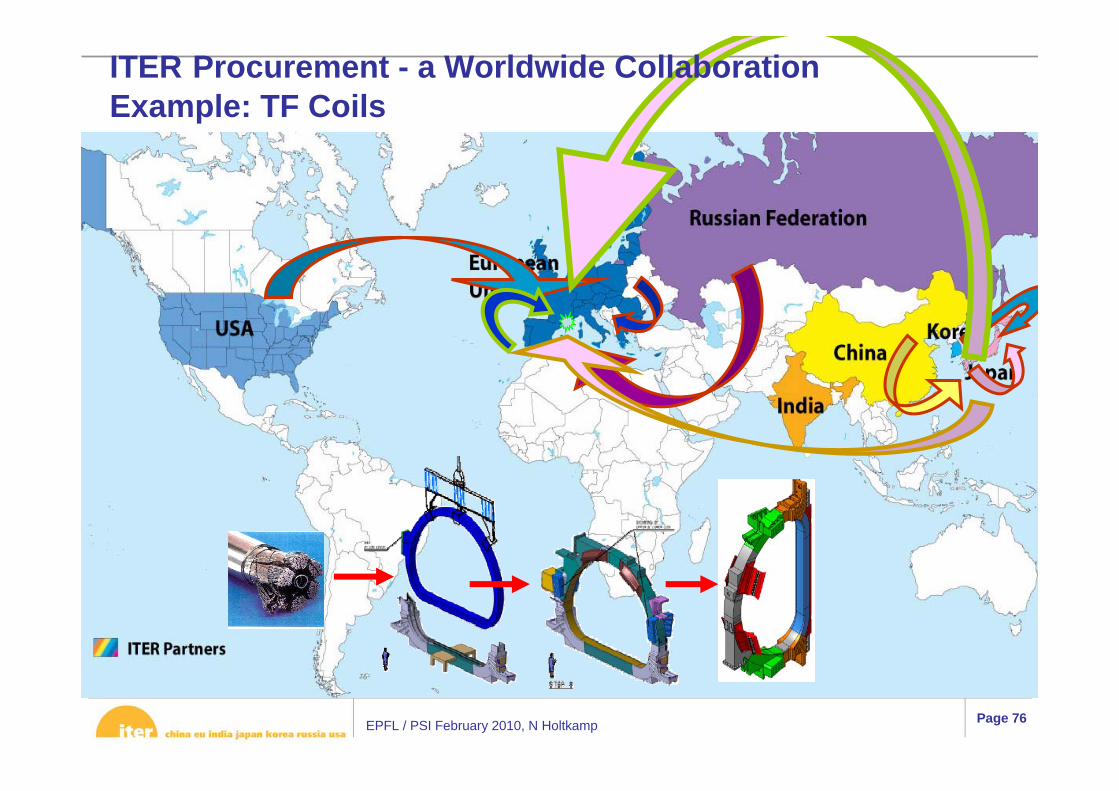
ITER Procurement - a Worldwide CollaborationExample: TF Coils
EPFL / PSI February 2010, N Holtkamp Page 77
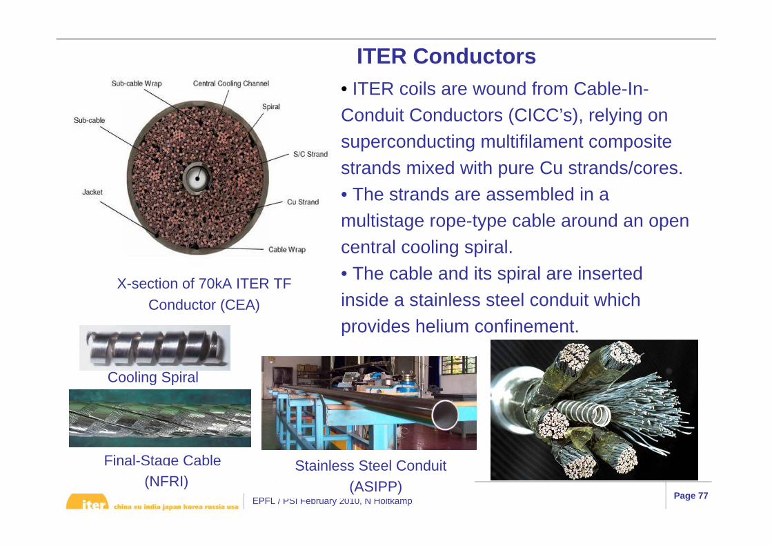
ITER Conductors
Cooling Spiral
• ITER coils are wound from Cable-In-Conduit Conductors (CICC’s), relying on superconducting multifilament composite strands mixed with pure Cu strands/cores.• The strands are assembled in amultistage rope-type cable around an open central cooling spiral.• The cable and its spiral are inserted inside a stainless steel conduit which provides helium confinement.
Stainless Steel Conduit
X-section of 70kA ITER TF Conductor (CEA)
Final-Stage Cable
(ASIPP)(NFRI)
EPFL / PSI February 2010, N Holtkamp Page 78
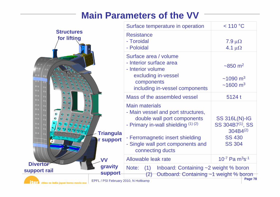
Note: (1) Inboard: Containing ~2 weight % boron(2) Outboard: Containing ~1 weight % boron
10-7 Pa m3s-1Allowable leak rate
SS 316L(N)-IGSS 304B7(1), SS
304B4(2)
SS 430SS 304
Main materials- Main vessel and port structures,
double wall port components- Primary in-wall shielding (1) (2)
- Ferromagnetic insert shielding- Single wall port components and
connecting ducts
5124 tMass of the assembled vessel
~850 m2
~1090 m3
~1600 m3
Surface area / volume- Interior surface area- Interior volume
excluding in-vessel components
including in-vessel components
7.9 μΩ4.1 μΩ
Resistance- Toroidal- Poloidal
< 110 °CSurface temperature in operation
Main Parameters of the VV
Triangular support
Structures for lifting
Divertor support rail
VV gravity support
EPFL / PSI February 2010, N Holtkamp Page 79
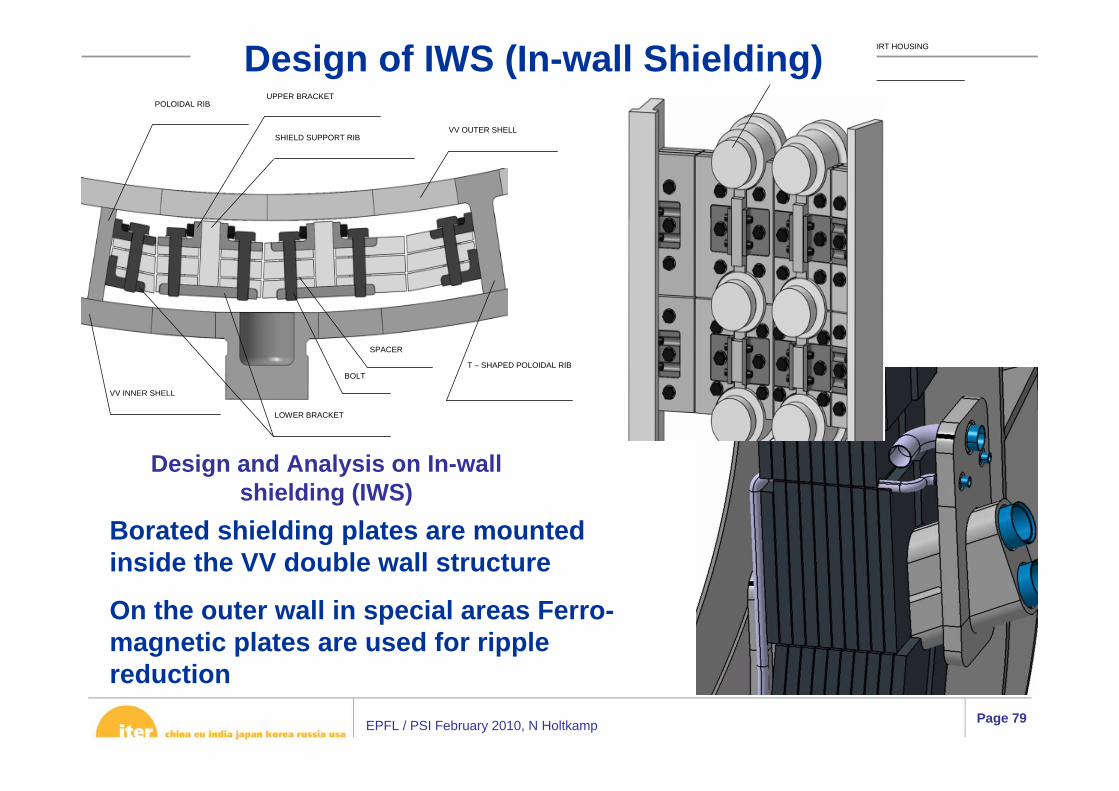
VV OUTER SHELL
T – SHAPED POLOIDAL RIB
POLOIDAL RIBUPPER BRACKET
VV INNER SHELL
LOWER BRACKET
BOLT
SPACER
SHIELD SUPPORT RIB
BLANKET FLEXIBLE SUPPORT HOUSING
Design and Analysis on In-wall shielding (IWS)
Design of IWS (In-wall Shielding)
Borated shielding plates are mounted inside the VV double wall structure
On the outer wall in special areas Ferro-magnetic plates are used for ripple reduction

EPFL / PSI February 2010, N Holtkamp Page 80
ITER Fuel Cycle
Apart from the cryogenic guard vacuum – exhausts are centralized and controlled
T-Plant handles all exhaust gases – release limits !!
EPFL / PSI February 2010, N Holtkamp Page 81
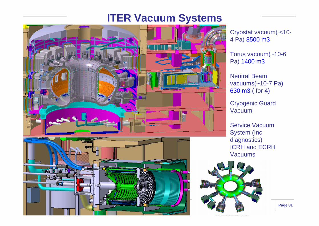
ITER Vacuum SystemsCryostat vacuum( <10-4 Pa) 8500 m3
Torus vacuum(~10-6 Pa) 1400 m3
Neutral Beam vacuums(~10-7 Pa)630 m3 ( for 4)
Cryogenic Guard Vacuum
Service Vacuum System (Inc diagnostics) ICRH and ECRH Vacuums
EPFL / PSI February 2010, N Holtkamp Page 82
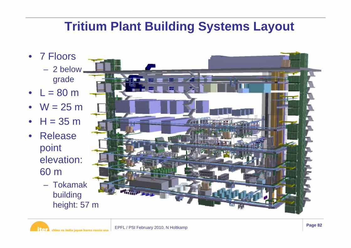
Tritium Plant Building Systems Layout
• 7 Floors– 2 below
grade
• L = 80 m• W = 25 m• H = 35 m• Release
point elevation:60 m– Tokamak
building height: 57 m
EPFL / PSI February 2010, N Holtkamp Page 83
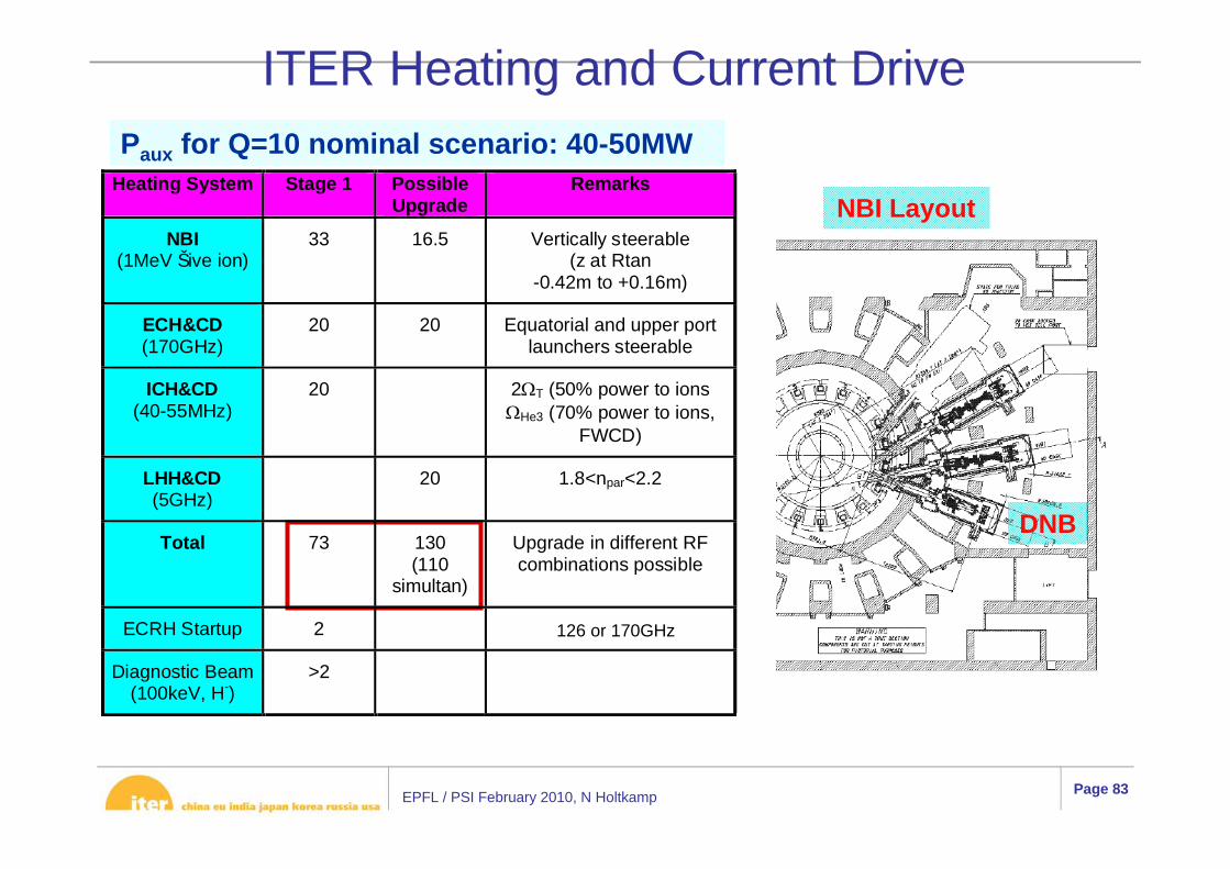
Paux for Q=10 nominal scenario: 40-50MW
NBI Layout
DNB
120GHz
Heating System Stage 1 PossibleUpgrade
Remarks
NBI(1MeV Šive ion)
33 16.5 Vertically steerable(z at Rtan
-0.42m to +0.16m)
ECH&CD(170GHz)
20 20 Equatorial and upper portlaunchers steerable
ICH&CD(40-55MHz)
20 2ΩT (50% power to ionsΩHe3 (70% power to ions,
FWCD)
LHH&CD(5GHz)
20 1.8<npar<2.2
Total 73 130(110
simultan)
Upgrade in different RFcombinations possible
ECRH Startup 2
Diagnostic Beam(100keV, H-)
>2
ITER Heating and Current Drive
126 or 170GHz
EPFL / PSI February 2010, N Holtkamp Page 84
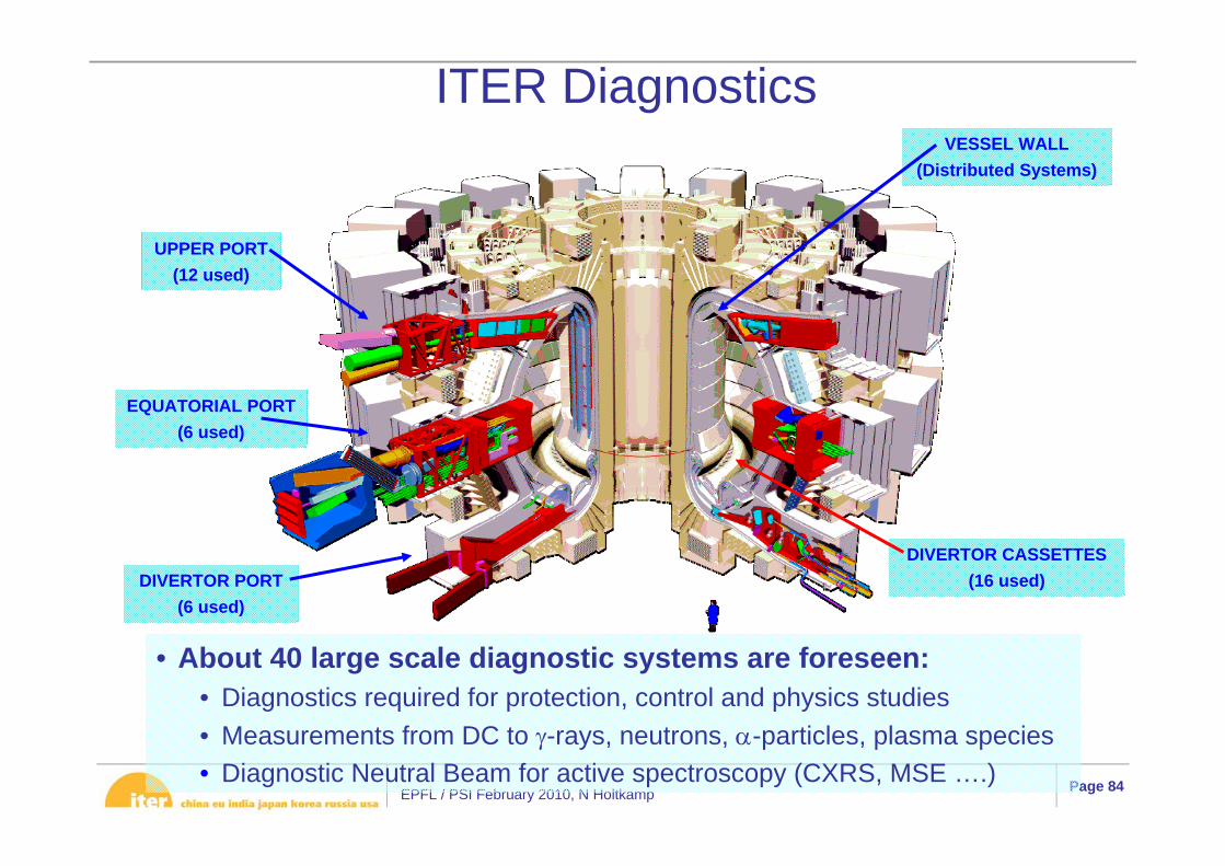
• About 40 large scale diagnostic systems are foreseen:• Diagnostics required for protection, control and physics studies• Measurements from DC to γ-rays, neutrons, α-particles, plasma species• Diagnostic Neutral Beam for active spectroscopy (CXRS, MSE ….)
UPPER PORT(12 used)
EQUATORIAL PORT(6 used)
DIVERTOR PORT(6 used)
DIVERTOR CASSETTES(16 used)
VESSEL WALL(Distributed Systems)
ITER Diagnostics

EPFL / PSI February 2010, N Holtkamp Page 85
Jacket Assy
Cable
Wrap
Sub-Wrap
4 th Stage
3rd Stage
2nd Stage
1st Stage
Cu Core Cable
Cu Sub-Cable
ConductorStrand
Cu Wire
JacketCentral Spiral