Embed Size (px)
Citation preview
HO
LD
ER
GU
IDE
PO
ST S
ETS
150
100
38
38
80
60
40
20
00 5 10
P
Deflectionδ〔mm〕
Load
P〔K
N〕
N-MYP38-250(Integrated type)
Fracture pointMounting bolt brokenHolder(cast part) broken
MYP38-250(Conventional product)
Conventional product
Holder
Material: FC250
Post
Material: S45C
Integrated unit
Material: S45C
Integrated type
Post and holder are machined
separately and assembled later.
Defl
ectionδ
Pressure rod
Hexagon socket head cap screw
Fixing jig
Test piece①N-MYP38-250(Integrated type)②MYP38-250(Conventional product)Load application speed: 0.5mm/sec.
Test instrument: SHIMAZU(UH-F100A)
HOLDER GUIDE POST SETS
Product name PLAIN GUIDE POST SETS OIL-FREE GUIDE POST SETS INTEGRATED TYPE PLAIN GUIDE POST SETS -OIL TYPE- INTEGRATED TYPE PLAIN GUIDE POST SETS -OIL-FREE TYPE-Catalog No. MY MYP MYZ MYZP N-MYP N-MYZP
Page 945 945 947 947
HOLDER GUIDE
POST SETS
BALL GUIDE POST SETS -MOVABLE STOPPER- BALL GUIDE POST SETS -FIXED STOPPER-MYA MYAP MYJ MYJP MYAK MYKP MYJK MJKP
949 951 951
INTEGRATED TYPE PLAIN GUIDE POSTS BUSHINGS FOR INTEGRATED TYPE PLAIN GUIDE POST SET GUIDE POST SETS WITH OIL GROOVES GUIDE POSTSN-MGP N-MGBP N-MGBZP MGOH MGOHP MGO MGP
953 954 955 957
GUIDE HOLDERS PLAIN GUIDE BUSHINGS OIL-FREE GUIDE BUSHINGS BALL GUIDE BUSHINGS BALL RETAINERS STOPPERSMGH MGHP MGB MGBP MGBZ MGBZP MAB MABP MBSH MBJH MBS MBJ STMY
958 958 958 959 959 960
WASHERS FOR PREVENTING DOWEL PIN FALL-OUT SPRINGS OIL-FREE GUIDE POST SETS OIL-FREE GUIDE BUSHINGS SPACERS FOR GUIDE POST SETSMW SWMY GPZE GBZE MGBPS MABPS MGHPS
960 960 961 962 963
SPACERS FOR GUIDE POST SETS STROKE END BLOCKS STROKE END BLOCKS -FLAT TYPE- CHAINS FOR END BLOCKSMGSPS MGLPS CEB CSB EBS EBW CEB□ CSB□ EBYS EBAS RSC
965 967 969 970
HOLDER GUIDE POST SETS-GUIDE 1-
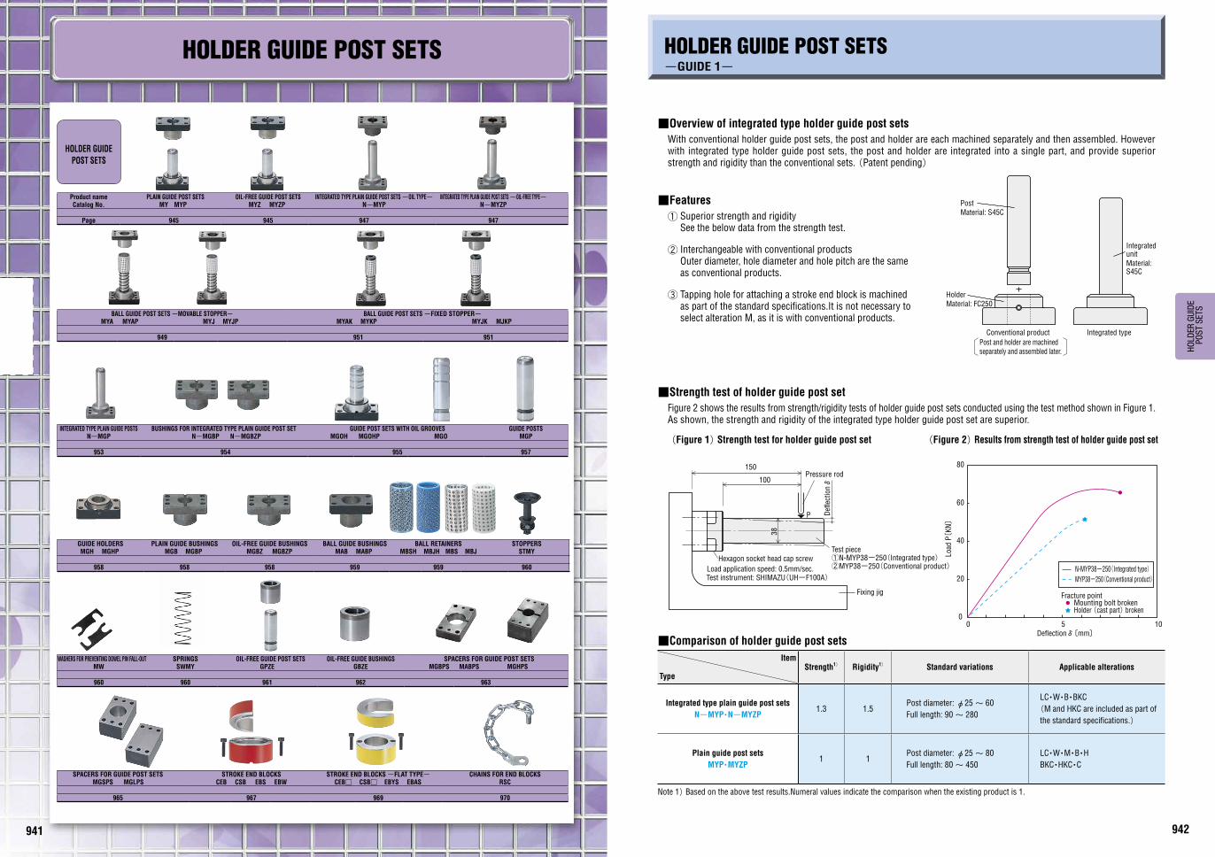
■Overview of integrated type holder guide post sets
With conventional holder guide post sets, the post and holder are each machined separately and then assembled. However with integrated type holder guide post sets, the post and holder are integrated into a single part, and provide superior strength and rigidity than the conventional sets. (Patent pending)
■Features
① Superior strength and rigidity See the below data from the strength test.
② Interchangeable with conventional products Outer diameter, hole diameter and hole pitch are the same as conventional products.
③ Tapping hole for attaching a stroke end block is machined as part of the standard specifications.It is not necessary to select alteration M, as it is with conventional products.
■Strength test of holder guide post set
Figure 2 shows the results from strength/rigidity tests of holder guide post sets conducted using the test method shown in Figure 1.As shown, the strength and rigidity of the integrated type holder guide post set are superior.
(Figure 1) Strength test for holder guide post set (Figure 2) Results from strength test of holder guide post set
■Comparison of holder guide post sets
Item
TypeStrength1) Rigidity1) Standard variations Applicable alterations
Integrated type plain guide post sets
N-MYP・N-MYZP1.3 1.5
Post diameter: φ25~ 60
Full length: 90~ 280
LC・W・B・BKC
(M and HKC are included as part of
the standard specifications.)
Plain guide post sets
MYP・MYZP1 1
Post diameter: φ25~ 80
Full length: 80~ 450
LC・W・M・B・H
BKC・HKC・C
Note 1) Based on the above test results.Numeral values indicate the comparison when the existing product is 1.
942941

943 944
HO
LD
ER
GU
IDE
PO
ST S
ETS
■Holder guide post set alterations -Guide- The following alterations cannot be used for some types. Refer to the relevant pages.
Alteration Code Spec. D 1Code
Post length change LC
1mm increments
LCmin.≦LC<Lmax.
If the length is shorter than the standard L dimension
for a ball type, check the height at BDC.
P.971~ 974
Tap hole for attaching stroke
end block
Bushing
W
Tap holes are machined for attaching a stroke end block.
( For the specifications of stroke end blocks, refer to P.967~ 970)
25・32
38・50
60・80
Holder
M Cannot be used for D20. Alteration W cannot be used for ball guide types.
25~ 80
Machining for reversed bushing
and/or holder orientation
Bushing
B
The flange surfaces are altered.Use of the reversed bushing
and/or holder allows the die height to be reduced.
Reduction in die height(mm)
20・25・32
38・50
60・80
Holder
H Can be combined with alterations W and M. In this case, the tap hole will be machined from the opposite direction.
Alteration H cannot be used for integrated types.
Be sure to select this alteration when
using in the reversed orientation.
The post length is measured from the
holder bottom.
Bushing H1 dimension
tolerance changeBKC
Bushing height H1 dimension tolerance is
changed from±0.2 to ±0.1.
H1±0.2⇨±0.1
25・32
38・50
60・80
Holder H dimension
tolerance change HKC
Holder height H dimension tolerance is
changed from±0.2 to ±0.1.
H±0.2⇨±0.1
25・32
38・50
60・80
Addition of locating dowel holes (2 holes)
N
2 locating dowel holes are
machined on the holder.
Dowel pins are not
provided.
Can be used only for types
without dowel holes.
20・25・32
38・50
60・80
Addition of locating dowel hole
(1 hole at center)C
1 locating dowel hole is machined at the
center of the post.
Dowel pin is not provided.
20・25・32
38・50
60・80
Ball retainer achange
BSC
The provided ball retainer is changed to a
high rigidity type.
Aluminum: MBSH
Resin : MBJH
1Code
■Accuracy standardsInspection item Measurement Tolerance
Perpendicularity of guide
holder bottom
and guide post
0.02/100 or less
H1±
0.1
H±
0.1
(ℓ/2)±0.01
N
2-φeH7
25
φ10H7A
φ0.04 A
1
M
M
H±
0.1
S
S
M
H±
0.1
L
LC
Bushing
Holder
Bushing
Holder
Holder bottom
ℓ
ℓ1
HOLDER GUIDE POST SETS-ALTERATIONS GUIDE / ACCURACY STANDARDS-
HOLDER GUIDE POST SETS-GUIDE 2-
■Replacement parts of holder guide post sets
TypeCatalog No.
of set
Replacement parts (catalog No. and page)
Post Holder Bushing Retainer Spring Stopper
Plain guide post sets -Oil type-
MY
MGP (P.957)
MGH (P.958) MGB (P.958)- - -
MYP MGHP (P.958) MGBP (P.958)
Plain guide post sets -Oil-free type-
MYZ MGH (P.958) MGBZ (P.958)- - -
MYZP MGHP (P.958) MGBZP (P.958)
Integrated type plain guide post sets -Oil type-
N-MYP
N-MGP (P.953)
N-MGBP(P.954)
- - -Integrated type plain
guide post sets -Oil-free type-
N-MYZP N-MGBZP(P.954)
Ball guide post sets
MYA
Not available
MGH (P.958) MAB (P.959)MBS (P.959)
SWMY (P.960)
STMY (P.960)MYAP MGHP (P.958) MABP (P.959)
MYJ MGH (P.958) MAB (P.959)MBJ (P.959)
MYJP MGHP (P.958) MABP (P.959)
MYAK MGH (P.958) MAB (P.959)MBS (P.959)
Not availableMYKP MGHP (P.958) MABP (P.959)
MYJK MGH (P.958) MAB (P.959)MBJ (P.959)
MJKP MGHP (P.958) MABP (P.959)
Guide post sets with oil grooves
MGOHMGO (P.955)
MGH (P.958)- - - -
MGOHP MGHP (P.958)
GPZE MGP (P.957) - GBZE (P.962) - - -
D LCmin.20 7525 7532 9538 12050 16560 17080 240
Pla
in t
ype 20・25・32
38・50
60・80
Bal
l typ
e 20・25・32
38・50
60
D M ℓ1 S25
4 1237
32 4538 5
1560
50 6 7260
8 2092
80 116
D Plain bushing Ball bushing Holder side20 25 35 1525 25 30 1032 30 40 2038 35 45 2550 60 65 4060 70 70 4580 95 - 65
D ℓ e20 56 625 66 832 76 838 100 1050 125 1060 150 1380 190 16
D Retainer length MBSH MBJH20 5025 5032 6038 7050 9060 100

945 946
HO
LD
ER
GU
IDE
PO
ST S
ETS
D A B a b d H H1 T (Q) ℓ a1 b1 eH7 ④Provided bolt ⑤Provided dowel pins
20 74 44 56 30 6.6 30 40 15 42 56 28 15 6 +0.012 0 CB 6-30 MSTM 6-20
25 84 48 66 30 9 30 45 20 46 66 33 15 8
+0.015 0
CB 8-35 MSTM 8-3032 100 58 76 36 11 40 50 20 56 76 38 18 8 CB10-40 MSTM 8-3038 130 75 100 44 11 50 60 25 73 100 50 22 10 CB10-45 MSTM10-4050 155 90 125 60 14 65 85 25 87 125 62.5 30 10 CB12-50 MSTM10-4060 190 120 150 80 18 75 100 30 116 150 75 40 13 +0.018
0CB16-60 MSTM13-50
80 230 150 180 110 22 100 130 35 145 190 90 55 16 CB20-75 MSTM16-60
Catalog No.L
Base unit price 1~9 piecesType D MY MYP MYZ MYZP
MY
MYP
MYZ
MYZP
2080 90 100 110 120
130 140 150 160
2580 90 100 110 120
130 140 150 160 170 180 200
3290 100 110 120 130 140
150 160 170 180 200 220 250
38110 120 130 140 150 160 170 180
200 220 250 280 300
50160 170 180 200 220 250
280 300 350
60180 200 220 250 280 300
350 400
80250 280 300 350
400 450
In accordance with safety standards for the transport of heavy items, φ80 posts include M12 tap holes, and can be hoisted up for transport by means of lifting eye bolts.
Catalog No. - L
MYZP 50 - 250
PLAIN GUIDE POST SETS-OIL・OIL-FREE TYPES-
MY(Oil type) MYP(With dowel hole, oil type)
⑤④
Replacement parts P.943
① ~ FC250
② ~ S45C
55HRC~(Induction hardening)
③ ~ FC250
MYZ(Oil-free type) MYZP(With dowel hole, oil-free type)
④ ⑤
Replacement parts P.943
① ~ FC250
Special solid lubricant(embedded)
② ~ S45C
55HRC~(Induction hardening)
③ ~ FC250
Perpendicularity of guide holder bottom and guide post: 0.02mm/100mm or less(Refer to P.944.)
H±
0.2
T2H
L
T
H1±
0.2
H 2
4-φd
2-φe
a1 a1
b1
b1
b B
a
A
±0.012
25
6.3
6.3
25
25
25
①
①
② ②
③
③
ℓ
D
±0.01ℓ
2ℓ
(Q)
(Q)
A
a
Bb
b1
b1
a1a1
2-φe
4-φd
H1±
0.2
T
L
D
TH±
0.2
2H
25
25
6.3
25
25
6.3
H 2③
③
② ②
①
①
ℓ
±0.01 ±0.012ℓ
2ℓ
(Q)
(Q)
Price
Alterations
Alteration Code Spec. D 1Code
L
LC
SM
H±0.
1ℓ1
Bushing
Holder
Holder bottom
LC
Post length change 1mm increments LCmin.≦LC<Lmax.
Details of alteration P.944
20・25・32
38・50
60・80
Bushing W
Machining for mounting of a stroke end block Tap holes are machined for attaching a stroke end block.
Cannot be used for D20.
Details of alteration P.944
25・32 38・50 60・80
Holder
M25~80
Bushing
B
Machining of flange for reversed bushing and/or holder orientation Use of the reversed bushing and/or holder allows the die height to be reduced. Alterations B and H can be
combined at the same time. The post length is measured
from the holder bottom.Details of alteration P.944
20・25・32
38・50
60・80Holder
H
Catalog No. - L(LC)-(M・B・H・N・C, etc.)
MYZP 50 - LC240 - B-H
Days to Ship
Order
Alteration Code Spec. D 1Code
H1±
0.1
H±
0.1
2-φeH7
N
ℓ(ℓ/2)±0.01
25
φ0.04 Aφ10H7A
BKC
Bushing H1 dimension tolerance change H1±0.2 ⇨ ±0.1
Cannot be used for D20.
25・32
38・50
60・80
HKC
Holder H dimension tolerance change H±0.2 ⇨ ±0.1
Cannot be used for D20.
25・32
38・50
60・80
N
Addition of locating dowel holes 2 locating dowel holes are machined on the holder.
20・25・32
38・50
60・80 Can be used
for MY・MYZ.
Dowel pins are not provided.
C
Addition of locating dowel hole
(1 hole at center) Locating dowel hole is machined at center of post.
Dowel pin is not provided.
20・25・32
38・50
60・80
D ℓ e20 56 625 66 832 76 838 100 1050 125 1060 150 1380 190 16
(Q)values are reference only.
(Q)values are reference only.
947 948
HO
LD
ER
GU
IDE
PO
ST S
ETS
D A B d H H1 T (Q) ℓ a1 b1 S M ℓ1 eH7 ③Provided bolt ④Provided dowel pins
25 84 48 9 30 45 20 46 66 33 15 37 4 12 8
+0.015 0
CB 8-35 MSTM 8-30
32 100 58 11 40 50 20 56 76 38 18 45 4 12 8 CB10-40 MSTM 8-30
38 130 75 11 50 60 25 73 100 50 22 60 5 15 10 CB10-45 MSTM10-40
50 155 90 14 65 85 25 87 125 62.5 30 72 6 15 10 CB12-50 MSTM10-40
60 190 120 18 75 100 30 117 150 75 40 92 8 20 13 +0.018 0 CB16-60 MSTM13-50
Catalog No.L
Base unit price 1~9 pieces
Type D N-MYP N-MYZP
N-MYP
N-MYZP
2590 100 110 120
130 140 150 160 170 180 200
32100 110 120 130 140 150
160 170 180 200
38
120 130 140 150
160 170 180
200 220 250
50160 170 180 200
220 250
N-MYZP 60 180 200 220 250 280
Catalog No. - L
N-MYP 50 - 250
Catalog No. - L(LC)-(W・B, etc.)
N-MYP 50 - LC240 - B
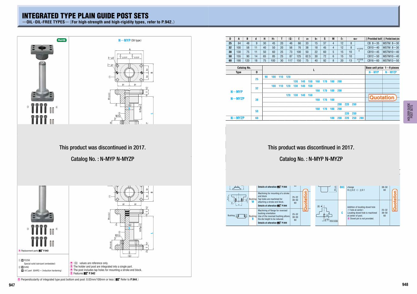
INTEGRATED TYPE PLAIN GUIDE POST SETS-OIL・OIL-FREE TYPES-(For high-strength and high-rigidity types, refer to P.942.)
N-MYP(Oil type)
④③
Replacement parts P.943
4-φd
2-φe
H1±
0.2
H±
0.05
T
L
Tb
1b
1
B
A
2
D
①
②
6.3
25
25
25
25
6.3S
±0.01
a1 a1
M×ℓ1
ℓℓ
2 ±0.01ℓ
※P
art
C(Q)
(Q)
① ~ FC250
② ~ S45C
※C part 55HRC~(Induction hardening)
(Q)values are reference only. The holder and post are integrated into a single part. The post includes tap holes for mounting a stroke end block. Features P.942
N-MYZP(Oil-free type)
③ ④
Replacement parts P.943
H1±
0.2
H±
0.05
2 ±0.01
25
S
25
25
25
6.3
T
L
4-φd
①
2-φe
a1 a1
6.3
T
B
b1b1
A
ℓℓ
2 ±0.01ℓ
※P
art
C
②M×ℓ1
D
(Q)
(Q)
① ~ FC250
Special solid lubricant(embedded)
② ~ S45C
※C part 55HRC~(Induction hardening)
(Q)values are reference only. The holder and post are integrated into a single part. The post includes tap holes for mounting a stroke end block. Features P.942
Perpendicularity of integrated type post bottom and post: 0.02mm/100mm or less( Refer to P.944.)
Alteration Code Spec. D 1Code
L
LC
ℓ1
SM
M
H±
0.1
Bushing
LC
Post length change 1mm increments LCmin.≦LC<Lmax.
Details of alteration P.944
25・32 38・50
60
Bushing W
Machining for mounting of a stroke end block Tap holes are machined for attaching a stroke end block.
Details of alteration P.944
25・32 38・50
60
Bushing B
Machining of flange for reversed bushing orientation Use of the reversed bushing allows the die height to be reduced.
Details of alteration P.944
25・32 38・50
60
Alteration Code Spec. D 1Code
H1±
0.1
25
φ0.04 Aφ10H7
A
BKCBushing H1 dimension tolerance change H1±0.2 ⇨ ±0.1
25・32 38・50
60
C
Addition of locating dowel hole
(1 hole at center) Locating dowel hole is machined at center of post.
Dowel pin is not provided.
25・32 38・50
60
Price
Alterations
Days to Ship
Order
This product was discontinued in 2017.
Catalog No. : N-MYP N-MYZP
This product was discontinued in 2017.
Catalog No. : N-MYP N-MYZP

949 950
HO
LD
ER
GU
IDE
PO
ST S
ETS
D D1 A B a b d H H1 T (Q) Ls M Stopper distance ℓ a1 b1 eH7 ⑥Provided bolts ⑦Provided dowel pins
20 26 74 44 56 30 6.6 30 50 15 42 50 0~20 56 28 15 6 +0.012 0 CB 6-30 MSTM 6-20
25 31 84 48 66 30 9 30 50 20 46 50 0~20 66 33 15 8
+0.015 0
CB 8-35 MSTM 8-30
32 40 100 58 76 36 11 40 60 20 56 60 0~25 76 38 18 8 CB10-40 MSTM 8-30
38 48 130 75 100 44 11 50 70 25 73 70 0~29 100 50 22 10 CB10-45 MSTM10-40
50 60 155 90 125 60 14 65 90 25 87 90 0~42 125 62.5 30 10 CB12-50 MSTM10-40
Catalog No.L
Base unit price 1~9 pieces
Type D MYA MYAP MYJ MYJP
MYA
MYAP
MYJ
MYJP
2090 100 110 120
130 140 150 160
25
90 100 110 120
130 140 150 160
170 180 200
32
110 120 130 140 150
160 170 180 200
220 240 260
38
130 140 150 160
170 180 200 220
240 260 300
50
170 180 200
220 240 260
300 350
OrderCatalog No. - L
MYJ 25 - 90
Days to Ship
Catalog No. - L(LC)-(M・B・H・N・C…etc.)
MYAP 50 - LC230 - B-H
BALL GUIDE POST SETS-MOVABLE STOPPER-(ALUMINUM・RESIN BALL CAGE)
T
LM
T
D
H±
0.2
Ls
H1±
0.2
a1a1
b1
b1
4-φd
a
b B
A
0
D1
2-φe
±0.01
+0.
005
25
25
25
6.3
6.3
25①
①
②
③ ③
②
④ ④
⑤ ⑤
ℓℓ2 ±0.01
ℓ2
(Q)
(Q)
Replacement parts P.943
Spring sizes P.960
①⑤ ~ FC250
② ~ SUJ2
58HRC~③ ~ Aluminum alloy
④ ~ SUJ2
58HRC~(Induction hardening)
T
LM
T
D
H±
0.2
Ls
H1±
0.2
a1a1
b1
b1
2-φe
4-φd
a
b B
A
+0.
005
D1
±0.01
25
25
25
6.3
25
6.3
0
③
①
④
⑤⑤
③
④
①
②
②
ℓℓ2 ±0.01
ℓ2
(Q)
(Q)
Replacement parts P.943
Spring sizes P.960
①⑤ ~ FC250
② ~ SUJ2
58HRC~③ ~ POM (Polyacetal resin) ④ ~ SUJ2
58HRC~(Induction hardening)
Perpendicularity of guide holder bottom and guide post: 0.02mm/100mm or less(Refer to P.944.)
Price
⑥ ⑦
⑥ ⑦
MYA(Aluminum type) MYAP(Aluminum type with dowel hole)
MYJ(Resin type) MYJP(Resin type with dowel hole)Alterations
Alteration Code Spec. D 1Code
L
LC
SM
H±0.
1ℓ1
Bushing
Holder
Holder bottom
LC
Post length change 1mm increments LCmin.≦LC<Lmax.
Details of alteration P.944
20・25・32
38・50
Holder M
Machining for mounting of a stroke end block Tap holes are machined for attaching a stroke end block. Cannot be used for D20. Details of alteration P.944
25~50
Bushing B
Machining of lange for reversed bushing and/or holder orientation Use of the reversed bushing and/or holder allows the die height to be reduced. �Alterations B and H can be
combined at the same time. �The post length is measured from
the holder bottom.Details of alteration P.944
20・25・32
38・50Holder
H
Alteration Code Spec. D 1Code
H1±
0.1
H±
0.1
2-φeH7
N
ℓ(ℓ/2)±0.01
25
φ0.04 Aφ10H7A
BKC
Bushing H1 dimension tolerance change
H1±0.2 ⇨ ±0.1
Cannot be used for D20.
25・32
38・50
HKC
Holder H dimension tolerance change H±0.2 ⇨ ±0.1
Cannot be used for D20.
25・32
38・50
N
Addition of locating dowel holes 2 locating dowel holes are machined
on the holder.
Can be used for MYA and MYJ.
Dowel pins are not provided.
20・25・32
38・50
C
Addition of locating dowel hole
(1 hole at center) Locating dowel hole is machined at center of post.
Dowel pin is not provided.
20・25・32
38・50
BSC
Ball retainer change Provided ball cage is changed to the high-rigidity type. Aluminum: MBSH Resin : MBJH
1Code
D ℓ e20 56 625 66 832 76 838 100 1050 125 10
D Retainer length MBSH MBJH20 5025 5032 6038 7050 90 (Q)values are reference only.
(Q)values are reference only.

951 952
HO
LD
ER
GU
IDE
PO
ST S
ETS
D D1 A B a b d H H1 T (Q) K Stopper ixed E Ls ℓ a1 b1 eH7 ⑥Provided bolt ⑦Provided dowel pins
25 31 84 48 66 30 9 30 50 20 46 20 5 50 66 33 15 8
+0.015 0
CB 8-35 MSTM 8-30
32 40 100 58 76 36 11 40 60 20 56 25 5 60 76 38 18 8 CB10-40 MSTM 8-30
38 48 130 75 100 44 11 50 70 25 73 30 10 70 100 50 22 10 CB10-45 MSTM10-40
50 60 155 90 125 60 14 65 90 25 87 40 10 90 125 62.5 30 10 CB12-50 MSTM10-40
60 70 190 120 150 80 18 75 100 30 116 50 15 100 150 75 40 13 +0.018 0 CB16-60 MSTM13-50
Catalog No.L
Base unit price 1~9 piecesType D MYAK MYKP MYJK MJKP
MYAK
MYKP
MYJK
MJKP
2590 100 110 120
130 140 150 160170 180 200
32110 120 130 140 150
160 170 180 200220 240 260
38130 140 150 160
170 180 200 220240 260 300
50170 180 200
220 240 260300 350
60200 220
240 260300 350
OrderCatalog No. - L
MYKP 50 - 200
BALL GUIDE POST SETS-FIXED STOPPER-(ALUMINUM・RESIN BALL CAGE)
H±
0.2
D
25
25
6.3
T
L
A
4-φd
Ls
25
H1±
0.2
K
25
ET
6.3
+0.
005
D10
a
2-φe
Bb
a1 a1
±0.01
b1
b1
ℓℓ2 ±0.01
ℓ2
⑤
③
④
①
②
⑤
③
④
①
②
(Q)
(Q)
Replacement parts P.943
Spring sizes P.960
①⑤ ~ FC250
② ~ SUJ2
58HRC~③ ~ Aluminum alloy
④ ~ SUJ2
58HRC~(Induction hardening)
H±
0.2
D
25
T
6.3
25
L
4-φd
Ls
25
H1±
0.2
K
25
E
6.3
T
0+0.
005
D1
a
A
Bb
2-φe
a1 a1
±0.01b
1b
1
ℓℓ2 ±0.01
ℓ2
⑤
③
④
①
②
⑤
③
④
①
②
(Q)
(Q)
Replacement parts P.943
Spring sizes P.960
①⑤ ~ FC250
② ~ SUJ2
58HRC~③ ~ POM(Polyacetal resin) ④ ~ SUJ2
58HRC~(Induction hardening)
Perpendicularity of guide holder bottom and guide post: 0.02mm/100mm or less(Refer to P.944.)
Price
Days to Ship
Catalog No. - L(LC)-(M・B・H・N・C…etc.)MYJK 50 - LC230 - B-H
Alteration Code Spec. D 1Code
L
LC
SM
H±0.
1ℓ1
Bushing
Holder
Holder bottom
LC
Post length change 1mm increments LCmin.≦LC<Lmax.
Details of alteration P.944
25・32
38・50
60
Holder M
Machining for mounting of a stroke
end block Tap holes are machined for attaching a stroke end block.
Details of alteration P.944
25~60
Bushing B
Machining of flange for reversed bushing and/or holder orientation Use of the reversed bushing and/or holder allows the die height to be reduced. �Alterations B and H can be
combined at the same time. �The post length is measured
from the holder bottom.Details of alteration P.944
25・32
38・50
60Holder H
Alteration Code Spec. D 1Code
H1±
0.1
H±
0.1
ℓ
25
φ0.04 A
2-φeH7
N
φ10H7A
(ℓ/2)±0.01
BKCBushing H1 dimension tolerance change H1±0.2 ⇨ ±0.1
25・32
38・50
60
HKCHolder H dimension tolerance change H±0.2 ⇨ ±0.1
25・32
38・50
60
N
Addition of locating dowel holes Locating dowel holes are machined on holder.
(2 positions)25・32
38・50
60
�Can be used for MYAK and MYJK.
�Dowel pins are not provided.
C
Addition of locating dowel hole
(1 hole at center) Locating dowel hole is machined at center of post.
Dowel pin is not provided.
25・32
38・50
60
BSC
Ball retainer change Provided ball cage is changed to the high rigidity type. Aluminum: MBSH Resin : MBJH
1Code
D ℓ e25 66 832 76 838 100 1050 125 1060 150 13
D Retainer length MBSH MBJH25 5032 6038 7050 9060 100
⑥ ⑦
⑥ ⑦
MYAK(Aluminum type) MYKP(Aluminum type with dowel hole)
MYJK(Resin type) MJKP(Resin type with dowel hole)
Alterations
(Q)values are reference only.
(Q)values are reference only.

953 954
HO
LD
ER
GU
IDE
PO
ST S
ETS
BUSHINGS FOR INTEGRATED TYPE PLAIN GUIDE POST SETINTEGRATED TYPE PLAIN GUIDE POSTS(For high-strength and high-rigidity types, refer to P.942.)
N-MGP
2-φe
b1
b1
a1 a1
ℓ
4-φd
M×ℓ1
S
A
B
H±
0.05
6.3
T
25
25
L
Dn5
※P
art
C
2±0.01ℓ
2±0.01ℓ
(Q)
�The holder and post are integrated into a single part.
�The post includes tap holes for mounting a stroke end block.
�Perpendicularity of integrated type post bottom and post:
0.02mm/100mm or less( Refer to P.944.)
~ S45C
※Part C 55HRC~(Induction hardening)
Dn5 A B d H T (Q) ℓ a1 b1 S M ℓ1 eH7
25 +0.024 +0.015 84 48 9 30 20 46 66 33 15 37 4 12 8
+0.015 0
32+0.028 +0.017
100 58 11 40 20 56 76 38 18 45 4 12 8
38 130 75 11 50 25 73 100 50 22 60 5 15 10
50 155 90 14 65 25 87 125 62.5 30 72 6 15 10
60 +0.033 +0.020 190 120 18 75 30 117 150 75 40 92 8 20 13 +0.018
0
Catalog No.L
Base unit price
Type D 1~9 pieces
N-MGP
2590 100 110 120
130 140 150 160 170 180 200
32100 110 120 130 140 150
160 170 180 200
38
120 130 140 150
160 170 180 200
220 250
50160 170 180 200
220 250
60 180 200 220 250 280
OrderCatalog No. - L
N-MGP 32 - 200
Days to Ship
Price
AlterationsCatalog No. - L(LC)-(C)
N-MGP50 - LC240 - C
Alteration Code Spec. D 1Code
L
LC25
φ0.04 Aφ10H7
A
LC
Post length change 1mm increments LCmin.≦LC<Lmax.
Details of alteration P.944
25・32 38・50
60
C
Addition of locating dowel hole
(1 hole at center) Locating dowel hole is machined at center of post.
Dowel pin is not provided.
25・32 38・50
60
N-MGBP (Oil type)
N-MGBZP (Oil-free type)
~ FC250 ~ FC250 Special solid lubricant(embedded)
A B d H1 T (Q) eH7 ℓ a1 b1Catalog No. Base unit price 1~9 pieces
Type D N-MGBP N-MGBZP
84 48 9 45 20 468
+0.015 0
66 33 15
N-MGBP
N-MGBZP
25 +0.041 +0.031
100 58 11 50 20 56 76 38 18 32 +0.047 +0.037
130 75 11 60 25 7310
100 50 22 38 +0.049 +0.037
155 90 14 85 25 87 125 62.5 30 50 +0.052 +0.037
190 120 18 100 30 117 13 +0.018 0 150 75 40 N-MGBZP 60 +0.061
+0.043
OrderCatalog No.
N-MGBP 25N-MGBZP 32
Days to Ship
Price
AlterationsCatalog No. -(W・B・BKC)
N-MGBP 25 - B
Alteration Code Spec. D 1Code Alteration Code Spec. D 1Code
M
H±0.
1
ℓ1
S
Bushing
Bushing W
Machining for mounting of a stroke end block Tap holes are machined for attaching a stroke end block. Details of alterationP.944
25・32
38・50
60 H1±
0.1
BKCBushing H1 dimension tolerance change H1±0.2 ⇨ ±0.1
25・32
38・50
60
Bushing
B
Machining of flange for reversed bushing orientation Use of the reversed bushing allows the die height to be reduced. Details of alterationP.944
25・32
38・50
60
■Integrated type plain guide posts -Guide-P.942
■Integrated type plain guide posts P.947
D
T
H1±0.2H1±0.2
T
a1a1
b1 b1
2-φe
2±
0.01
6.3
25 256.3
ℓ
ℓ
D
B
4-φd
A
2±
0.01
ℓ
(Q)
(Q)
(Q)values are reference only.
(Q)values are reference only.
This product was discontinued in 2017.
Catalog No. : N-MGP
This product was discontinued in 2017.
Catalog No. : N-MGBP N-MGBZP

955 956
HO
LD
ER
GU
IDE
PO
ST S
ETS
Alteration Code Spec. D 1Code
H±
0.1
25
φ0.04 Aφ10H7A
HKCHolder H dimension tolerance change
H±0.2 ⇨ ±0.1
25・32
38・50
60・80
C
Addition of locating dowel hole
(1 hole at center) Locating dowel hole is machined at center of post.
Dowel pin is not provided.
25・32
38・50
60・80
Alteration Code Spec. D 1Code
SM
H±0.
1ℓ1
Holder
Holder bottom
Holder M
Machining for mounting of a stroke end block Tap holes are machined for attaching a stroke end block.
Details of alteration P.944
25~80
Holder H
Machining of flange for reversed holder orientation Use of the reversed holder allows the die height to be reduced.
�The post length is measured from the holder bottom.
Details of alteration P.944
25・32
38・50
60・80
Dn5 M D A B a b d H T (Q) E F G h ℓ a1 b1 eH7 ③Provided bolts ④Provided dowel pins
25 +0.024 +0.015 - 25 84 48 66 30 9 30 20 46 13 13
3
15 66 33 15 8
+0.015 0
CB 8-35 MSTM 8-30
32+0.028 +0.017
- 32 100 58 76 36 11 40 20 56 15 15 20 76 38 18 8 CB10-40 MSTM 8-30
38 - 38 130 75 100 44 11 50 25 73 18 18 25 100 50 22 10 CB10-45 MSTM10-40
50 - 50 155 90 125 60 14 65 25 87 25 20
5
32.5 125 62.5 30 10 CB12-50 MSTM10-40
60 +0.033 +0.020
- 60 190 120 150 80 18 75 30 116 25 20 37.5 150 75 40 13 +0.018 0
CB16-60 MSTM13-50
80 12 80 230 150 180 110 22 100 35 145 30 25 50 190 90 55 16 CB20-75 MSTM16-60
Catalog No.L
Base unit price 1~9 pieces
Type D MGOH MGOHP MGO
MGOH MGOHP MGO
2580 90 100 110 120
130 140 150 160 170 180 200
32100 110 120 130 140
150 160 170 180 200 220 250
38120 130 140 150 160 170 180
200 220 250 280 300
50160 170 180 200 220 250
280 300 350
60180 200 220 250 280 300
350 400
80250 280 300 350
400 450
In accordance with safety standards for the transport of heavy items, φ80 posts include M12 tap holes, and can be hoisted up for transport by means of lifting eye bolts.
OrderCatalog No. - L
MGOH 32 - 200
Days to Ship
GUIDE POSTS WITH OIL GROOVES
MGOH MGOHP(With dowel hole)
① ~ S45C 55HRC~(Induction hardening) ② ~ FC250
(Q)values are reference only. Perpendicularity of guide holder bottom and guide post: 0.02mm/100mm or less(Refer to P.944.)
MGO(Guide post with oil grooves)
h
-0.3-0.03
D
E30
G0.2
Dn5
G
-0.
3L
0
FF
M12R30
Dn5
(In case of φD80)
When assembling on site, press-fit using a hydraulic press.
~ S45C
55HRC~(Induction hardening)
2-φe
A
a
Bb
±0.01
b1
b1
H±
0.2
4-φdH 2
6.3
T
25
FF
25
Dn5
G
L
E
a1 a1
② ②
① ①
ℓ
±0.012ℓ
2ℓ
(Q)
Price
③ ④
Catalog No. - L -(M・H・HKC・C)
MGOHP 50 - 250 - HAlterations
This product was discontinued in 2017.
Catalog No. : MGO

957 958
HO
LD
ER
GU
IDE
PO
ST S
ETS
Guide holders
(Q)values are reference only.
When assembling on site, press-fit using a hydraulic press. R FC250
Catalog No.A B a b d H T (Q) M eH7 ℓ a1 b1
Base unit price 1~9 pieces
Type Dk6 MGH MGHP
MGH
MGHP
20 +0.002 -0.011
74 44 56 30 6.6 30 15 42
8
6 +0.012 0 56 28 15
25 84 48 66 30 9 30 20 468
+0.015 0
66 33 15
32+0.003 -0.013
100 58 76 36 11 40 20 56 76 38 18
38 130 75 100 44 11 50 25 7310
100 50 22
50 155 90 125 60 14 65 25 87
12
125 62.5 30
60 +0.004 -0.014
190 120 150 80 18 75 30 116 13 +0.018 0
150 75 40
80 230 150 180 110 22 100 35 145 16 190 90 55
Plain guide bushings
R FC250
Oil-free guide bushings
R FC250
Special solid lubricant(embedded)
Catalog No.A B a b d H1 T (Q) eH7 ℓ a1 b1
Base unit price 1~9 pieces
Type D MGB MGBP MGBZ MGBZP
MGB
MGBP
MGBZ
MGBZP
20 +0.041 +0.031
74 44 56 30 6.6 40 15 42 6 +0.012 0 56 28 15
25 84 48 66 30 9 45 20 468
+0.015 0
66 33 15
32 +0.047 +0.037 100 58 76 36 11 50 20 56 76 38 18
38 +0.049 +0.037 130 75 100 44 11 60 25 73
10100 50 22
50 +0.052 +0.037 155 90 125 60 14 85 25 87 125 62.5 30
60 +0.061 +0.043 190 120 150 80 18 100 30 116 13 +0.018
0
150 75 40
80 +0.063 +0.043 230 150 180 110 22 130 35 145 16 190 90 55
T
H±0.2
Dk6 a A
b
B
4-φd
b1 b1
2±
0.01
a1a1
2-φe
6.3
25 25
ℓ
ℓ2±
0.01
ℓM
(Q)
H1±0.2
T
D
4-φd
a A
b
B
a1a1
b1 b1
2-φe
2±
0.01
6.3
25
ℓ
ℓ
2±0.01
ℓ
(Q)
D
T
H1±0.2
±0.
012
2-φe
b1b1
a1a1
b
Aa
4-φd
B
256.3
ℓ
ℓ
±0.01
2ℓ
(Q)Alteration Code Spec. D 1Code
H1±
0.1
H±
0.1
Bushing
Holder
Holder bottom
Bushing
B
Machining of flange for reversed bushing and/or holder orientation Use of the reversed bushing and/or holder allows the die height to be reduced. Alterations B and H can be
combined at the same time. The post length is measured
from the holder bottom.
Details of alteration P.944
20・25・32 38・50 60・80Holder
H
BKC
Bushing H1 dimension tolerance change H1±0.2 ⇨ ±0.1
Cannot be used for D20.
25・32 38・50 60・80
HKC
Holder H dimension tolerance change H±0.2 ⇨ ±0.1
Cannot be used for D20.
25・32 38・50 60・80
AlterationsCatalog No. - L(LC)-(W・B…etc.)
MGP80 - LC290 - B
Alteration Code Spec. D 1Code
LCL
SM
H±0.
1ℓ1
LC
Post length change LC<L 1mm incrementsDetails of alteration P.944
20・25・32 38・50 60・80
Bushing W
Machining for mounting of a stroke end block Tap holes are machined for attaching a stroke end block.
Cannot be used for D20.
Details of alteration P.944
25・32 38・50 60・80
Holder M 25~80
GUIDE POSTS / GUIDE HOLDERS / GUIDE BUSHINGS
Guide posts MGP
When assembling on site, press-fit using a hydraulic press.R S45C
Q 55HRC~(Induction hardening)
Dn5 hCatalog No.
LBase unit price
Type D 1~9 pieces
20+0.024 +0.015
15
MGP
2080 90 100 110 120
130 140 150 160
25 15 2580 90 100 110 120
130 140 150 160 170 180 200
32
+0.028 +0.017
20 3290 100 110 120 130 140
150 160 170 180 200 220 250
38 25 38110 120 130 140 150 160 170 180
200 220 250 280 300
50 32.5 50160 170 180 200 220 250
280 300 350
60+0.033 +0.020
37.5 60180 200 220 250 280 300
350 400
80 50 80250 280 300 350
400 450
OrderCatalog No. - L
MGP 32 - 160MGH 32
R30
M12
-0.30
L
30h
D
Dn5
0.2
-0.
03-
0.3 (In case of φD80)
Price
MGH MGHP(With dowel hole)
MGB MGBP(With dowel hole)
MGBZ MGBZP(With dowel hole)Days to Ship
(Q)values are reference only.
(Q)values are reference only.

959 960
HO
LD
ER
GU
IDE
PO
ST S
ETS
STOPPERS / WASHERS FOR PREVENTING DOWEL PIN FALL-OUT / SPRINGS FOR BALL GUIDE POST SETSBALL GUIDE BUSHINGS / BALL RETAINERS
Ball guide bushings MAB MABP(With dowel hole)
~ FC250 ~ SUJ2 58HRC~
Catalog No.D A B a b d H1 T (Q) eH7 ℓ a1 b1
Base unit price 1~9 piecesType PD MAB MABP
MAB
MABP
20 26
+0.005 0
74 44 56 30 6.6 50 15 42 6 +0.012 0 56 28 15
25 31 84 48 66 30 9 50 20 468
+0.015 0
66 33 1532 40 100 58 76 36 11 60 20 56 76 38 1838 48 130 75 100 44 11 70 25 73
10100 50 22
50 60 155 90 125 60 14 90 25 87 125 62.5 30
60 70 190 120 150 80 18 100 30 116 13 +0.018 0 150 75 40
OrderCatalog No.
MAB 32Days to Ship Price
MBSH(High-rigidity aluminum ball retainers)
MBJH(High-rigidity resin ball retainers)
�Compared with conventional ball retainer(MBS, MBJ), these products contain 1.6 times more balls.
~ ①A5056(Aluminum) ②POM(Polyacetal resin) ③SUJ2 Sphericity 0.25µm
③62~67HRC
MBS(Aluminum ball retainers)
MBJ(Resin ball retainers)
~ ①A5056(Aluminum) ②POM(Polyacetal resin) ③SUJ2 Sphericity 0.25µm
③62~67HRC
PD Post
diameter
Outer diameter φD
Inner diameter φD1
Ball diameter φd
Number of ballsRatio
Catalog No.L
Base unit price 1~9 piecesMBSH MBJH
MBS MBJ Type PD MBSH MBJH MBS MBJ
20 25.5 20.53
165 96 1.72MBSH
(Aluminum)
MBJH (Resin)
MBS (Aluminum)
MBJ (Resin)
20 5025 30.5 25.5 224 125 1.79 25 5032 39.5 32.5 4 238 144 1.65 32 6038 47.5 38.5
5210 128 1.64 38 70
50 59.5 50.5 360 220 1.64 50 9060 69.5 60.5 460 264 1.74 60 100
③d
PDDD1
L
L
D1 D PD
③d
Stoppers STMY
φP
D
5
φD
tH S
M×P
B
ℓSpring pin
MBS/MBJ Ball cage length
STMY
S ℓ
50 0~20 32
60 0~25 40
70 0~29 44
90 0~42 57
Catalog No.D M×P H B t
Base unit priceType PD-L 1~9 pieces
STMY
20-50 24 14×1.512
71.625-50 29 16×1.5 8
32-60 3720×1.5 15 1038-70 44
2.050-90 56
OrderCatalog No.
STMY 32-60Price
Washers for preventing dowel pin fall-out
MW ● Installation method: After setting the guide bushing in place, loosen the bolt and install the washer.
●One set contains two washers.
~ SPCC Thickness=1.6mm
Black oxide (Fe3O4)
Post diameter PD Catalog No.
Base unit price for 1 set(2 pcs.)1~19 sets
20・25
MW
2532 3238 3850 5060 6080 80
OrderCatalog No.
MW 38
Days to Ship
Price
Springs for ball guide post sets SWMY
D1 D
FL
PD
P d
~ SWP-B
PD Post diameter D D1 d P
20 22.5 20.5 +1.0 0
1.0 1425 27.9 25.5 1.2 1432 35.7 32.5 +1.5
01.6 16
38 42.5 38.5 2.0 1850 55.7 50.5 +2.0
02.6 20
60 66.9 60.5 3.2 20
●Solid height≒FL×d
P +2d
Guide post sets Catalog No.FL Base unit price
D L Type PD 1~9 pieces
20
90
SWMY
20
40100 50110 70120 80130 100140 110150 120160 140
25
90
25
40100 50110 70120 80130 100140 110150 120160 140170 150180 160200 180
Guide post sets Catalog No.FL Base unit price
D L Type PD 1~9 pieces
32
110
SWMY
32
50120 60130 70140 90150 110160 120170 130180 140200 170220 190240 210260 230
38
130
38
60140 70150 80160 90170 110180 120200 150220 170240 190260 210300 230
Guide post sets Catalog No.FL Base unit price
D L Type PD 1~9 pieces
50
170
SWMY
50
70180 90200 110220 140240 170260 190300 230350 280
60
200
60
90220 130240 150260 180300 230350 250
PriceOrderCatalog No. - L
MBSH 32 - 60
Days to Ship
① ②
① ②
Built-in bushing
Price
OrderCatalog No. - FL
SWMY 32 - 190
Days to Ship
Days to Ship
PD
4-φd
B
b
a A
±0.
012ℓ
2-φe
a1a1
ℓ
b1 b1
D
H1±0.2
T
0+
0.00
5
25 256.3
±0.
012ℓ
(Q)
(Q)values are reference only.
Refer to the P.957 lower part for Allterations.
MW

961 962
HO
LD
ER
GU
IDE
PO
ST S
ETS
OIL-FREE GUIDE BUSHINGS-PRESS-FIT TYPE-
OIL-FREE GUIDE POST SETS-PRESS-FIT TYPE-
GPZE
① ~ FC250
Special solid lubricant(embedded)② ~ S45C
55HRC~(Induction hardening)
② ①
Dn5 H1 dD1JS5
h h1 L1GPZE
32
+0.028 +0.017
20 32 +0.047 +0.037 52
±0.0065
8 4 48
38 25 38 +0.049 +0.037 60 10 5 55
50 32.5 50 +0.052 +0.037 70 15
10
75
60+0.033 +0.020
37.5 60 +0.061 +0.043 80 20 90
80 50 80 +0.063 +0.043 100 ±0.0075 25 120
D1Catalog No.
LBase unit price
Type D 1~9 pieces
52
GPZE
3290 100 110 120 130 140
150 160 170 180 200 220 250
60 38110 120 130 140 150 160 170 180
200 220 250 280 300
70 50160 170 180 200 220 250 280
300 350
80 60180 200 220 250 280 300
350 400
100 80250 280 300 350
400 450
D
Dn
5
Lh
L1
h1
H1
dD1
-0
.03
-0
.30
0.2
1.6
0.2
6.3
φ0.01 A
A
6.3
-0.1-0.3Press-in lead D
Price
Alteration Code Spec. D 1Code
LC
L
LCPost length change
LCmin.≦LC<Lmax.
1mm increments
32
38・50
60・80
D LCmin.32 8538 10550 14060 16580 220
GBZE
~ FC250
Special solid lubricant(embedded)
Catalog No. D1JS5h h1 L1
Base unit price 1~9 pieces
Type D GBZE GBZE
GBZE★
32 +0.047 +0.037 52
±0.0065
8 4 48
38 +0.049 +0.037 60 10 5 55
50 +0.052 +0.037 70 15
10
75
60 +0.061 +0.043 80 20 90
80 +0.063 +0.043 100 ±0.0075 25 120
D
h
D1
h1
L1
-0.1-0.3
6.3
0.2
1.6
6.3
A φ0.01 A
Press-in lead D①
②
AlterationsCatalog No. - L(LC)
GPZE 80 - LC 290
Days to Ship
OrderCatalog No.
GBZE 50Price
OrderCatalog No. - L
GPZE 80 - 300
Days to Ship

963 964
HO
LD
ER
GU
IDE
PO
ST S
ETS
Post diameter
A B a b d MF
*For ℓ±0.01
(*T60・70・80,) ℓ±0.02
eH7 TMGBPS MABPS MGHPS
20 74 44 56 30 6.6 6 22 28 - 56 6 +0.012 0 10 20 30 40
25 84 48 66 30 9 8 28 34 - 66 8
+0.015 0
10 20 30 40 50
32 100 58 76 36 11 10 34 42 - 76 8 10 20 30 40 50
38 130 75 100 44 11 10 42 52 32 100 10 20 30 40 50 60 70 80
50 155 90 125 60 14 12 52 62 45 125 10 20 30 40 50 60 70 80
Catalog No.T
TypePost
diameter
For plain type bushings
For ball type bushings
For holders
MGBPS
MABPS
MGHPS
20 10 20 30 40
25 10 20 30 40 50
32 10 20 30 40 50
38 20 30 40 50 60 70 80
50 20 30 40 50 60 70 80
SPACERS FOR GUIDE POST SETS-CAST TYPE-
Spacers for guide bushings
MGBPS(For plain types, with dowel holes)
MABPS(For ball types, with dowel holes)
2-φe
*ℓ±0.01(Dowel hole)
(T≧60
b/2
b/2
F b B
a
A
ℓ±0.02)
ℓ±0.02
T=10・20・30
T=40・50
T±0
.1
0.8G
0.8G
T±0.
1
0.8
0.8
G
G
4-φdφe
φe
φe
4-M
T=60・70・80
T±0.
1
0.8
0.8
G
G
4-M
*Dowel pitch
accuracy
Flatness of plate thickness: 0.02mm/100mm or less
Draft angle(2~3°)for casting is present in the direction of height T.
~ FC250
Spacers for guide holders
MGHPS(With dowel holes)
*ℓ±0.01(Dowel hole)
T=20・30
T=40・50
T=10・20・30
T=40・50
T±0.
1
T±0.
1
T±0
.1
T±0.
1b/
2b/
2
b B b Ba
A
0.8G
0.8G
0.8
0.8
G
G
0.8G
0.8G
0.8
0.8
G
GG
0.8G
4-φd
4-M
4-φdφe φe
φe
φe
φe 4-M
(T≧60 ℓ±0.02)
ℓ±0.02
T=60・70・80
T±0.
1
0.8
4-M
2-φe2-φe
F
a
A
*Dowel pitch
accuracy
Flatness of plate thickness: 0.02mm/100mm or less
Draft angle(2~3°)for casting is present in the direction of height T.
~ FC250
OrderCatalog No. - T
MGBPS 20 - 30
Example
T=40・50・60・70・80
= ・ ・
Post diameters: 20・25・32 Post diameters: 38・50
= ・ ・・ ・
T=10・20・30
Days to Ship
Price

965 966
HO
LD
ER
GU
IDE
PO
ST S
ETS
Post diameter
A B a b d MF *For ℓ±0.01
(*T60・70・80)
, ℓ±0.02
eH7 TMGSPS
20 74 44 56 30 6.6 6 28 56 6 +0.012 0 10 20 30 40
25 84 48 66 30 9 8 34 66 8
+0.015 0
10 20 30 40 50
32 100 58 76 36 11 10 42 76 8 10 20 30 40 50
38 130 75 100 44 11 10 52 100 10 20 30 40 50 60 70 80
50 155 90 125 60 14 12 62 125 10 20 30 40 50 60 70 80
Catalog No.T
Type Post diameter
For bushings MGSPS
For holders MGLPS
20 10 20 30 40
25 10 20 30 40 50
32 10 20 30 40 50
38 20 30 40 50 60 70 80
50 20 30 40 50 60 70 80
SPACERS FOR GUIDE POST SETS -STEEL TYPE-
Spacers for guide bushings
MGSPS(With dowel holes)
2-φe
b/2
b/2
T=20・30
T=40・50
T±0
.1
0.8G
0.8G
T±0
.1
0.8
0.8
G
G
F
4-φd
4-M
T=60・70・80
T±0
.1
0.8
0.8
G
G
4-M
4-M
(T≧60 ℓ±0.02)
A
a
b B
2-φe
b/2
b/2
T=10・20・30
T=40・50T±
0.1
0.8G
0.8G
T±0.
10.8
0.8
G
G
F
4-φdφe
φe φe
φe
φe
4-M
A
a
b B
ℓ1ℓ1
ℓ±0.02
*ℓ±0.01(Dowel hole) *ℓ±0.01(Dowel hole)
*Dowel pitch
accuracy
Flatness of plate thickness: 0.02mm/100mm or less ~ SS400
Spacers for guide holders
MGLPS(With dowel holes)
T=20・30
T=40・50
T=10・20・30
T=40・50
T±0
.1
T±0
.1
T±0
.1
T±0
.1
a
A
a
A
2-φe2-φe
0.8G
0.8G
0.8
0.8
G
G
0.8G
0.8G
0.8
0.8
G
G
G
G
4-φd
4-M
4-φd
4-M
T=60・70・80
T±0
.1
0.8
0.8
4-M
4-M
φe
φe φe
φe
φe
b/2
b/2
b B
b/2
b/2
b B
(T≧60 ℓ±0.02)
ℓ1ℓ1
ℓ±0.02
ℓ±0.01(Dowel hole)ℓ±0.01(Dowel hole)
*Dowel pitch
accuracy
Flatness of plate thickness: 0.02mm/100mm or less ~ SS400
Tℓ1(effective tap length)
Post diameter38 50
60 70 80
20 24
Tℓ1(effective tap length)
Post diameter38 50
60 70 80
20 24
Example
OrderCatalog No. - T
MGSPS 20 - 30
Post diameters: 20 ・ 25 ・ 32 Post diameters: 38 ・ 50
Post diameters: 20 ・ 25 ・ 32 Post diameters: 38 ・ 50
T=40・50・60・70・80
= ・ ・
= ・ ・・ ・
T=10・20・30
Days to Ship
Price

967 968
HO
LD
ER
GU
IDE
PO
ST S
ETS
①CEB(End block)
~ SS400
2 bolts
②CSB(Stock block)
~ SS400
PD D D1 D2 S h r1 r2 r3 A Bolt ℓ
25 46 31.5 36 37 2 15.75 18 23 22 M4×P0.7 10
32 56 41 45 45 2 20.5 22.5 28 27 M4×P0.7 10
38 72 49 56 60 3 24.5 28 36 35 M5×P0.8 10
50 86 62 68 72 3 31 34 43 42 M6×P1.0 10
60 112 76 84 92 3 38 42 56 55 M8×P1.25 12
80 140 100 108 116 3 50 54 70 69 M8×P1.25 12
■End blocks
Catalog No. H1 5mm increments
ColorBase unit price
Type PD 1~ 9 pieces
①CEB
25 10~ 50
R (Red)
Y
(Yellow)
3210~ 50
55・60
3815~ 5055~ 70
5020~ 5055~ 80
6020~ 5055~ 80
8020~ 5055~ 80
H1±0.1
PD
S
h
D1D
2 D PD
Bolt ℓ
H2±0.1 h
r2r1
r3
A
Catalog No. ①CEB(End block) ②CSB(Stock block) Base unit price 1~9 sets
Type PD H1 5mm increments Color H2 5mm increments Color EBW EBS
EBS
(①CEB+②CSB 1 piece) Set product
EBW
(①CEB+②CSB 2 piece) Set product
25 10~ 50
R (Red)
Y
(Yellow)
10~ 20
R (Red)
Y
(Yellow)
25~ 40
3210~ 50
10~ 2025~ 40
55・6010~ 2025~ 40
3815~ 50
10~ 2025~ 50
55~ 7010~ 2025~ 50
5020~ 50
10~ 2025~ 50
55~ 8010~ 2025~ 50
6020~ 50
10~ 2025~ 50
55~ 8010~ 2025~ 50
8020~ 50
10~ 2025~ 50
55~ 8010~ 2025~ 50
The guide post sets must be machined so that the blocks can be attached. P.944
OrderCatalog No. - ① - ②
Type PD H1 Color(R・Y) H2 - Color(R・Y)
EBS 38 - 40 R - 40 - Y
Days to Ship
STROKE END BLOCKS
■Stock blocks
Catalog No. H2 5mm increments
ColorBase unit price
Type PD 1~ 9 pieces
②CSB
2510~ 20
R (Red)
Y
(Yellow)
25~ 40
3210~ 2025~ 40
3810~ 2025~ 50
5010~ 2025~ 50
6010~ 2025~ 50
8010~ 2025~ 50
OrderCatalog No. - H1 - Color(R・Y)
CEB 32 - 35 - R
Days to Ship
Price
PD:Outside diameter of post
Price
AlterationsCatalog No. - ① - ② -(S・RS・HC)
EBW 38 - 40R - 40-Y - S-HC38
CSB 50 - 35-Y - RS
Alteration Machining for chain attachment Machining for reinforced chain (RSC) attachment H1 dimension change
Code S RS HC
Spec.
H1 dimension change H1 min.<HC<H1 max. 1mm increments
Cannot be used for CSB.End block and stock block are connected by a chain.
A reinforced chain is attached to stock block.
Can be used for PD≧25, H1≧20, and H2≧20.
Cannot be combined with alteration S.
1Code
No.PD EBW EBS EBW CSB・EBS CEB・EBS・EBW
253238506080
For chain RSC of alteration RS, P.970.
200
30
2.5
13
30
φ12
HC
Lifting eye bolt M10×20 with nut
This product was discontinued in 2017.
Catalog No. : CEB CSB EBS EBW
This product was discontinued in 2017.
Catalog No. : CEB CSB EBS EBW

969 970
HO
LD
ER
GU
IDE
PO
ST S
ETS
Catalog No. ①・②(End block) ③・④(Stock block) Base unit priceType PD H1 5mm increments Color H2 5mm increments Color 1~9 sets
EBYS
(①CEBY+③CSBY) Set product
EBAS
(②CEBA+④CSBA) Set product
2510~ 30
R (Red)
Y
(Yellow)
10~ 20
R (Red)
Y
(Yellow)
25~ 40
35~ 5010~ 2025~ 40
3210~ 30
10~ 2025~ 40
35~ 5010~ 2025~ 40
3815~ 30
10~ 2025~ 50
35~ 5010~ 2025~ 50
5020~ 30
10~ 2025~ 50
35~ 5010~ 2025~ 50
6020~ 30
10~ 2025~ 50
35~ 5010~ 2025~ 50
8020~ 30
10~ 2025~ 50
35~ 5010~ 2025~ 50
The guide post sets must be machined so that the blocks can be attached. P.944.
OrderCatalog No. - ①・② - ③・④
Type PD H1 Color(R・Y) H2 Color(R・Y)
EBYS 38 - 40 R - 40 Y
AlterationsCatalog No. - H(1・2)- Color(R・Y) -(S・RS・HC・NMC)
CSBY50 - 35 - R - RS
CEBA60 - 40 - Y - HC32
STROKE END BLOCKS-FLAT TYPE-
CEBY(End block for plain guide post)
CEBA(End blocxk for ball guide post)
~ SS400
2 bolts
CSBY(Stock block for plain guide post)
CSBA(Stock block for ball guide post)
~ SS400
PD DCEBY CEBA CSBY CSBA
S r2 Bolt ℓD1 D1 r1 r1
25 46 29 31.5 14.5 15.75 37 23 M4×P0.7 1032 56 37 41 18.5 20.5 45 28 M4×P0.7 1038 72 43 49 21.5 24.5 60 36 M5×P0.8 1050 86 56 62 28 31 72 43 M6×P1.0 1060 112 66 76 33 38 92 56 M8×P1.25 1280 140 88 100 44 50 116 70 M8×P1.25 12
■End blocksCatalog No. H1
5mm incrementsColor
Base unit priceType PD 1~9 pieces
CEBY
CEBA
25 10~ 50
R (Red)
Y
(Yellow)
32 10~ 60
38 15~ 70
50 20~ 80
60 20~ 80
80 20~ 80
H1±0.1
PD
SD1 D PD
Bolt
H2±0.1
C12r
1
r1
r2
ℓ
■Stock blocksCatalog No. H2
5mm incrementsColor
Base unit priceType PD 1~9 pieces
CSBY
CSBA
25 10~ 40
R (Red)
Y
(Yellow)
32 10~ 40
38 10~ 50
50 10~ 50
60 10~ 50
80 10~ 50
OrderCatalog No. - H1 - Color (R・Y)
CEBY 32 - 35 - R
Days to Ship
Price
Example
CEB□CSB□
CEB□
When stroke is adjustedWhen die is stored
Example
CEB□CSB□
CEB□
When stroke is adjustedWhen die is stored
Example
CEB□CSB□
CEB□
When stroke is adjustedWhen die is stored
Days to Ship
Price
Alteration Machining for chain attachment Machining for reinforced chain(RSC)attachment H1 dimension change Machining of grooveCode S RS HC NMC
Spec.
Lifting eye bolts M10×20 with nut
H1 dimension change H1 min.<HC<H1 max. 1mm increments
�Please order according to the alteration order example.
�Cannot be used for CSBY and CSBA.
Tap hole processing on the end block for chain mounting.Tap hole processing on the stock block for chain mounting.
The chain is attached to the stock block.
Cannot be combined with alteration RS.
Tap hole processing on the end block for a reinforced chain mounting.
�Reinforced chain(RSC)is attached to stock block.
Can be used for PD≧25, H1≧20, and H2≧20.
Cannot be combined with alteration S.
�Cannot be used for CSBY and CSBA.
Addition of a groove for height adjustment
Cannot be used for CSBY and CSBA.
1Code
■Chains for end blocks
RSC
T
200
30
13
2.5
30
25
φ12
③①
②
HC
H
1±0.1PD H25・32 10
38~ 80 15
~ �①�SS400 Bright chromate plating
②SPCC
③�SS400(Lifting eye bolt M10×20)with nut
Catalog No. Base unit price
Type T 1~9 pieces
RSC3
5
This product, RSC3, is a chain for alteration RS.
OrderCatalog No.
RSC 3
Days to Ship
Price
P22-15_0969-0970 初校
PD:Outside diameter of post This product was discontinued in 2017.
Catalog No. : EBYS EBAS
P22-15_0969-0970.indd 969-970 18.2.1 1:30:09 PM
971 972
HO
LD
ER
GU
IDE
PO
ST S
ETS
S1=2S
S1
HS
S
φD
φD
h h
15
h
M+
5h
10h
h
αα
α
Position where ball cage starts to move: Ideal
position for HS BDC(long contact length)
●Relationship between bushing movementrange S and ball cage movement range S1.
20
90
100
110
120
130
140
150
160
60 80 100 120 140 160 180 200 220
E B A
B A
B
E
E
E
E
F
F
F
140
E120
160
25 140
150
130 F
80
100
110
90
100
C
E
E
E B
120
A
180160 200 240220
170
180
200
180
200
160100
32
140
160
170
150
120
130
110
E
F
E
E
E
E
B
120
A
140 200180 220 240
240
220
260
260 280 300
D
180120
150
E
200
240
260
220
38
170
180
160
F
E
130
140
E
E
D C
B A
140 160 220200 240 280260 300 340320
300
D
B A
200
200
FF
300
240
260
22050
170
180
E
E
E
D
C
BC
B
A
160
A
180 240220 260 300280 320 340
350
380360
C
C
C
C
C
C
C
C
A
B A
B A
B A
B A
B A
C
C
C
C
F
F
F
F
F
F
C
C
C
C
C
C
B A
B A
B A
B A
B A
B A
B A
B A
B A
B A
B A
B A
B A
B A
B A
F
F
F
F
F
B A
B A
B A
B A
B A
C
C
C
C
C
C
C
C
C
C
C B A
F
F
F
F
C
C
C
C
C
C
C
C
C
B A
B A
B A
B A
B A
B A
B A
B A
B A
F
F
C B A
C B A
C B A
C B A
C B A
C B A
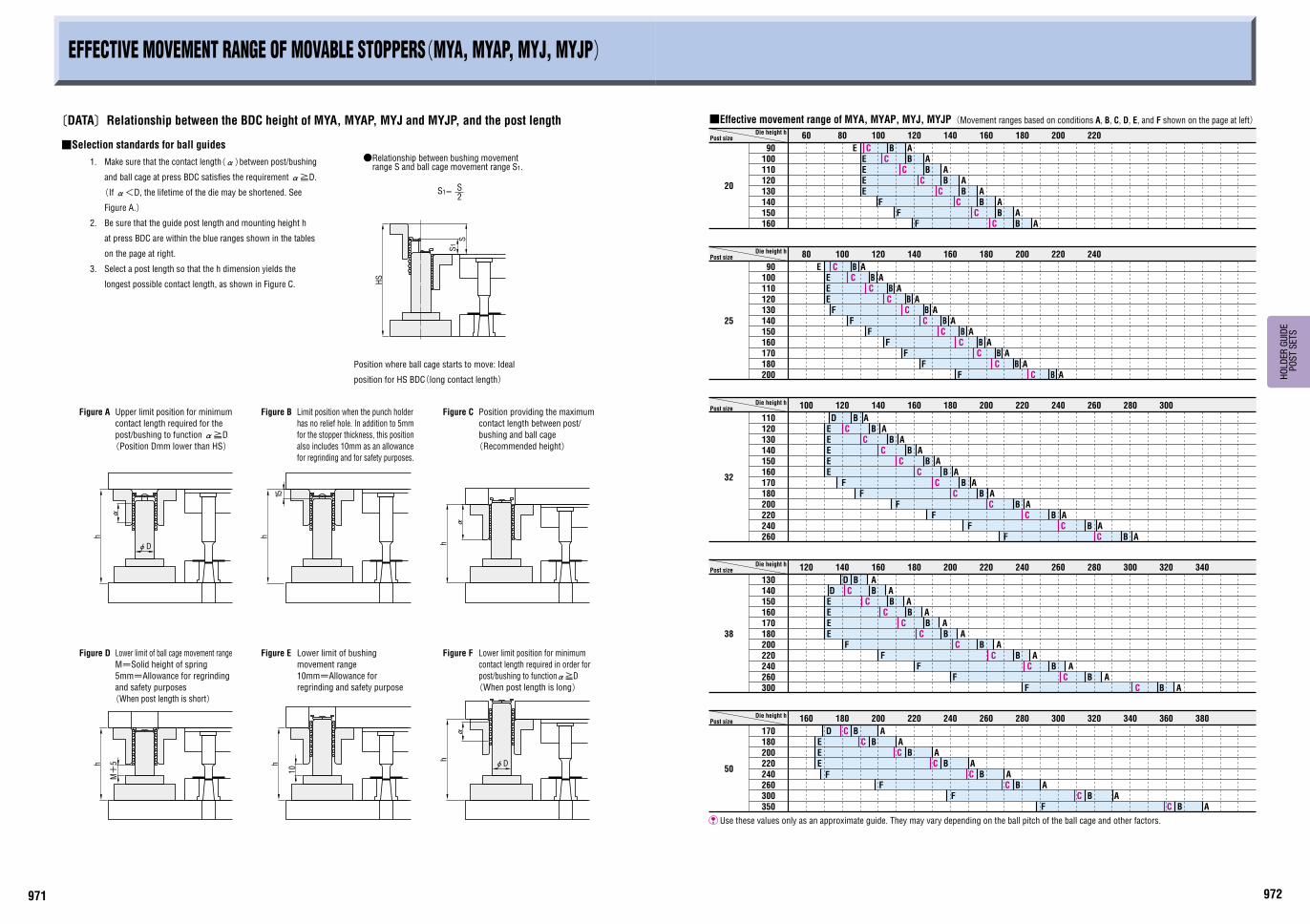
Use these values only as an approximate guide. They may vary depending on the ball pitch of the ball cage and other factors.
■Effective movement range of MYA, MYAP, MYJ, MYJP(Movement ranges based on conditions A, B, C, D, E, and F shown on the page at left)
Die height hPost size
Die height hPost size
Die height hPost size
Die height hPost size
Die height hPost size
EFFECTIVE MOVEMENT RANGE OF MOVABLE STOPPERS(MYA, MYAP, MYJ, MYJP)
〔DATA〕Relationship between the BDC height of MYA, MYAP, MYJ and MYJP, and the post length
■Selection standards for ball guides
1. Make sure that the contact length(α)between post/bushing
and ball cage at press BDC satisfies the requirement α≧D.
(If α<D, the lifetime of the die may be shortened. See
Figure A.)
2. Be sure that the guide post length and mounting height h
at press BDC are within the blue ranges shown in the tables
on the page at right.
3. Select a post length so that the h dimension yields the
longest possible contact length, as shown in Figure C.
Figure A Upper limit position for minimum
contact length required for the
post/bushing to function α≧D
(Position Dmm lower than HS)
Figure B Limit position when the punch holder
has no relief hole. In addition to 5mm
for the stopper thickness, this position
also includes 10mm as an allowance
for regrinding and for safety purposes.
Figure C Position providing the maximum
contact length between post/
bushing and ball cage
(Recommended height)
Figure D Lower limit of ball cage movement range
M=Solid height of spring
5mm=Allowance for regrinding
and safety purposes
(When post length is short)
Figure E Lower limit of bushing
movement range
10mm=Allowance for
regrinding and safety purpose
Figure F Lower limit position for minimum
contact length required in order for
post/bushing to functionα≧D
(When post length is long)

973 974
HO
LD
ER
GU
IDE
PO
ST S
ETS
h1
L+
K+
E
L
Th
10
1T
φD
h
h
M+
5h h
10
h φD
αα
α
(Example)h=190 In case of MYAK38-200
(Refer to P.1007)K+E : Height of fixed type stopper
L : Bolt length
Die
hei
ght
DH
Bolster
Ram
(10mm=Regrinding+Safety)
●How to determine T1
T1≧h1-h
T1≧250-190
T1 must be 60mm or longer.T1≧60
h1=L+K+E+10…Refer to left figure.
EFFECTIVE MOVEMENT RANGE OF FIXED TYPE STOPPERS(MYAK, MYKP, MYJK, MJKP)
〔DATA〕Relationship between the BDC height of MYAK, MYKP, MYJK and MJKP, and the post length
■Selection standards for ball guides
1. Make sure that the contact length(α)between post/bushing and ball cage at press BDC satisfies the requirement α≧D.
(If α<D, the lifetime of the die may be shortened. Figure A)
2. Be sure that the guide post length and mounting height h at press BDC are within the blue ranges shown in the tables on the page at right.
3. Select a post length so that the h dimension yields the longest possible contact length, as shown in Figure C.
Figure A Upper limit position for minimum
contact length required for the
post/bushing to function α≧D
(Position Dmm lower than HS)
Figure C Position providing the maximum
contact length between post/
bushing and ball cage
(Recommended height)
Figure D Lower limit of ball cage movement range
M=Solid height of spring
5mm=Allowance for regrinding
and safety purpose
(When post length is short)
Figure E Lower limit of bushing
movement range
10mm=Allowance for
regrinding and safety purpose
Figure F Lower limit position for minimum
contact length required in order
for post/bushing to function α≧D
90
100
110
120
130
140
150
160
170
180
200
25
80 100 120 140 160 180 200 220 240 260 280
125
135
145
155
165
175
185
195
205
215
235
1h
E
E
E
E
F
F A
F
F
F
E
D
CC
C
C
C
C
C
C
C
C
A
A
A
A
A
A
A
A
A
CE
120
160
220
180
17032
140
150
130
F
E
E
E
C
C
C
C
C
100
110
E
D
A
140120
A
C
C A
160
C
240200180 220 280260
180
220
300
260
240
210
190
h1
160
170
150
300
200
200
280240
260
D
C
C
F
F
F
F
170
360F
260
200
240
220
180
410
CE
E
50E
F
E
ED
160
200
180
170
38
140
150
130
F
E
F
E
160
D A
180
C
C
C
C
C
140120
C
160
260200 220 240
C
C
300280
240200180 220 280260
210
260
300
320
280
230
240
h1
270
350
310
290
230
250
220
h1
190
200
180
240
300
260
220
320300 340 360
D
F
FF
350
300
320 360340 380 400
F
C
180
E
26060
350
300
E
F
220
240
200 D A
220200 240 320280260 300 360340 380
335
425
375
400 h
295
315
275
1420
D
F
A
AD
A
A
A
A
A
A
A
A
A
A
A
A
A
A
AA
A
A
A
A
C
C
A
C AC A
C A
C A
C A
A
C A
C A
C A
C A
Use these values only as an approximate guide. They may vary depending on the ball pitch of the ball cage and other factors.
Die height hPost size
■Effective movement range of MYAK, MYKP, MYJK, MJKP(Movement ranges based on conditions A, C, D, E, and F shown on the page at left)
Die height hPost size
Die height hPost size
Die height hPost size
Die height hPost size