Embed Size (px)
Citation preview

1
History of Innovation & Inspiration The Model T E-Timer
By Mike Kossor, WA2EBY
An amazing thing about the Model T is the number of automotive innovations it has spawned over the years. A prime example of one such innovation is the original Model T ignition system which has been well documented1. The simplicity of design and shear elegant implementation is a true electro-mechanical marvel. The Model T has inspired countless refinements and improvements over its 100 year history. The subject of this article falls into this category with a slightly unusual twist. The improvement is significant and effective yet its existence must be imperceptible. The Model T feature targeted for improvement is, of course, the venerable electro-mechanical ignition system. Simple and elegant as it is, the fact remains, its components are often difficult to properly align and erode with normal operation. Finding original replacement points and timers are getting more difficult as time passes causing owners to sometimes trade originality for performance by installing modern replacement parts on their otherwise original car. The notion of a modern electronic ignition system immune to ware and unconstrained by the mechanical limitations of the original ignition system is only an attractive solution if its existence does not destroy originality, appearance or function of the original automobile. These goals present a considerable challenge, perhaps one worthy of the Model T tradition of innovation if successful. This article chronicles the evolution of just such an innovation that was indeed successful after a long educational endeavor that many will find of interest.
The original objectives of a Model T electronic ignition system were:
Eliminate Consumable Elements Points Timer contacts/rotor/brushes
Retain Originality Superior Performance
Initial Approach An imperceptible implementation vastly complicates the design choices. The obvious location to conceal the control electronics was the limited space within the timer housing. A review of what it takes to perform the electronic ignition function provides a better appreciation of the packaging challenge that had to be overcome. The basic approach is identical to the well known electronic ignition systems of modern cars: replace the roller with a magnetic actuator fixed to the CAM shaft and use Hall sensors to detect CAM shaft position. Then replace the timer contacts with their modern solid state equivalent; Insulated Gate Bipolar Transistor (IGBT) switches that can fire the coils when triggered by the respective Hall sensor. The coil points are no longer necessary and are typically bypassed (shorted) with a small wire jumper for best performance but the electronics will operate without this modification. The component count must be kept to an absolute minimum if it is to remain undetectable and fit within the confines of the timer housing. The first attempt, utilized a method in popular use today on modern cars; the wasted spark technique. While cylinder 1 is at Top Dead Center (TDC) of the compression stroke, cylinder 4 is at the end of the exhaust stroke (TDC). Cylinder 1 fires at
2
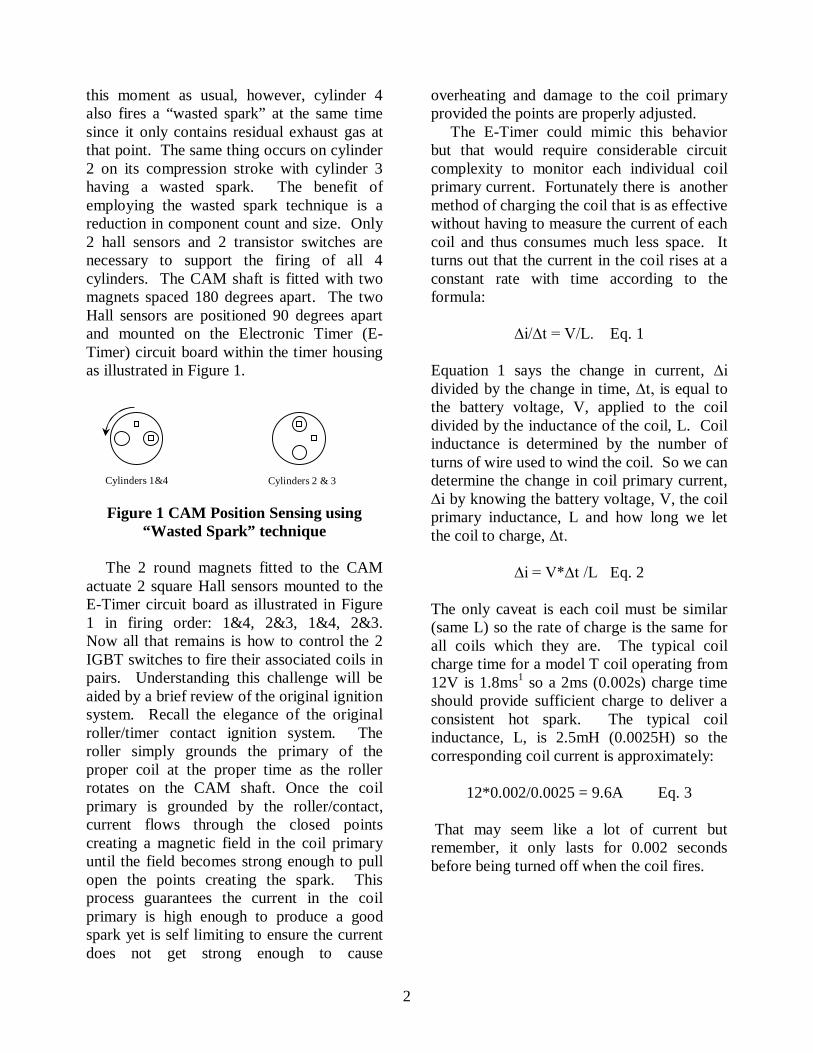
this moment as usual, however, cylinder 4 also fires a “wasted spark” at the same time since it only contains residual exhaust gas at that point. The same thing occurs on cylinder 2 on its compression stroke with cylinder 3 having a wasted spark. The benefit of employing the wasted spark technique is a reduction in component count and size. Only 2 hall sensors and 2 transistor switches are necessary to support the firing of all 4 cylinders. The CAM shaft is fitted with two magnets spaced 180 degrees apart. The two Hall sensors are positioned 90 degrees apart and mounted on the Electronic Timer (E-Timer) circuit board within the timer housing as illustrated in Figure 1.
Figure 1 CAM Position Sensing using
“Wasted Spark” technique The 2 round magnets fitted to the CAM actuate 2 square Hall sensors mounted to the E-Timer circuit board as illustrated in Figure 1 in firing order: 1&4, 2&3, 1&4, 2&3. Now all that remains is how to control the 2 IGBT switches to fire their associated coils in pairs. Understanding this challenge will be aided by a brief review of the original ignition system. Recall the elegance of the original roller/timer contact ignition system. The roller simply grounds the primary of the proper coil at the proper time as the roller rotates on the CAM shaft. Once the coil primary is grounded by the roller/contact, current flows through the closed points creating a magnetic field in the coil primary until the field becomes strong enough to pull open the points creating the spark. This process guarantees the current in the coil primary is high enough to produce a good spark yet is self limiting to ensure the current does not get strong enough to cause
overheating and damage to the coil primary provided the points are properly adjusted. The E-Timer could mimic this behavior but that would require considerable circuit complexity to monitor each individual coil primary current. Fortunately there is another method of charging the coil that is as effective without having to measure the current of each coil and thus consumes much less space. It turns out that the current in the coil rises at a constant rate with time according to the formula:
∆i/∆t = V/L. Eq. 1
Equation 1 says the change in current, ∆i divided by the change in time, ∆t, is equal to the battery voltage, V, applied to the coil divided by the inductance of the coil, L. Coil inductance is determined by the number of turns of wire used to wind the coil. So we can determine the change in coil primary current, ∆i by knowing the battery voltage, V, the coil primary inductance, L and how long we let the coil to charge, ∆t.
∆i = V*∆t /L Eq. 2
The only caveat is each coil must be similar (same L) so the rate of charge is the same for all coils which they are. The typical coil charge time for a model T coil operating from 12V is 1.8ms1 so a 2ms (0.002s) charge time should provide sufficient charge to deliver a consistent hot spark. The typical coil inductance, L, is 2.5mH (0.0025H) so the corresponding coil current is approximately:
12*0.002/0.0025 = 9.6A Eq. 3
That may seem like a lot of current but remember, it only lasts for 0.002 seconds before being turned off when the coil fires.
Cylinders 1&4 Cylinders 2 & 3

3
Ignition Control The next thing that had to be determined was how to implement the control electronics; discrete electronics or something more sophisticated. The initial thought was keep it simple using discrete components to process the signals between each Hall sensor and respective IGBT switch. But again, the shear quantity of components to implement the timing and control electronics would preclude fitting them within the volume constraints of the timer housing. A more sophisticated approach would clearly be needed. Fortunately, modern electronics provides an arsenal of powerful choices to accomplish such a task; the microcontroller! A miniature computer with self contained memory used to store programming information on how it is to function. A microcontroller based proto-type was designed and built. Bench testing confirmed its functionality accurately mimicked timer/roller operation firing each coil pair repeatedly when the respective CAM sensors were activated for as long as they were activated as described in Figure 1. The next step was engine performance testing. Performance Testing The proto-type E-Timer was installed on an ornate red 1909 touring car and powered with an external connection to the battery. Initial tests were very disappointing. The engine was really difficult to start by hand. Several sputters and back fires through the carburetor that were likely due to having the timing retarded while the waited spark fired in the cylinder on the exhaust stroke. That cylinder was now actually on the beginning of its intake stoke pulling in air/fuel mixture when the wasted spark fires. Obviously not a desirable trait for a hand cranked car. The engine did eventually start after an exhausting series of hand cranks. The immediate thought was there was something wrong with the E-Timer so the original timer/roller was re-installed and jumper wires were placed between coil primaries 1&4 and coil primaries 2&3 to produce wasted spark
timing. The exact same difficult starting symptoms were observed. It was not the E-Timer circuit. Use of the wasted spark technique to minimize component count was clearly not a viable option for a hand cranked engine. Ignition Control – Version 2 It was clear that four separate IGBTs would be needed to fire each ignition coil independently using four Hall sensors as illustrated in Figure 2. Things just got a little bit more crowed in the timer housing!
Figure 2 CAM Position Sensing
The CAM is fitted with 1 round magnets that actuate 4 square Hall sensors mounted to the E-Timer circuit board as illustrated in Figure 2 in firing order: 1, 2, 4, 3. Performance Testing – V2 Proto-type version 2 was installed again with external connection to the battery for power only this time the engine stated up on the very first crank. The engine seemed to idle well but drive testing still indicated something was lacking. The engine performance seems a bit rough considering the coil points were replaced by solid state IGBT switches that are precisely controlled by the E-Timer circuitry to charge and fire a spark consistently. I say the coil points were replaced but actually just bypassed by shorting them out with a wire. The coil points still vibrate and buzz just as they did originally, albeit a little more consistently, but no longer control firing spark. Understanding why engine performance was lacking would require considerable more work.
Cylinder 1 Cylinder 2 Cylinder 3 Cylinder 4

4
Electronic Ignition Diagnostics The E-Timer performs complex timing of 4 ignition coils that is difficult to capture on standard electronic instruments such as an oscilloscope which typically only permits monitoring of 2 simultaneous activities. A custom test set was designed that could emulate engine CAM shaft operation while monitoring CAM shaft position and all 4 E-Timer coil connections electronically. Figure 3 illustrates the CAD model used to design and build the final E-Timer test set.
Figure 3 E-Timer Test Set CAD Model
The test set consists of an engine body used to mount the E-Timer similar to the actual engine mounting. An electric motor drives the CAM shaft via cogged drive belt and pulleys. The CAM shaft is fitted with a position indicator wheel that has 4 slits in it used to sense positions of cylinders 1, 2, 3, and 4 at Top Dead Center (TDC) by an optical sensor. The test set employs a microcontroller that monitors the CAM position optical sensor and E-Timer coil terminals to determine when each coil fires with respect to the CAM position sensor. The data is then transferred to a laptop PC for display and analysis. The actual E-timer test set that was built and perfected to characterize E-Timer performance is illustrated in Figure 4.
Figure 4 E-Timer Test Set The E-Timer test set is capable of monitoring the firing of each coil in respect to the CAM position with resolution of 4 microseconds (0.000004s) or less than 0.25 degrees at 2000 RPM. E-Timer test results revealed that ignition timing between coils varied by as much as 7 crankshaft degrees. Side to side movement of the timer housing on the test fixture (a mere 0.02”) indicated an additional timing error of +/- 3 degrees for a total timing error of 10 degrees. All the work done to provide precision timing was for naught! What went wrong? Further research identified the root cause to be the way the Hall sensors were used to sense position and timing. Four different Hall sensors were employed actuated by a magnet. Each Hall sensor activated at a different level of magnetic field. The Hall sensor activation point also varied with the position of the magnet relative to the Hall sensor so timing error was also introduced if the CAM shaft did not turn exactly concentric about the Hall sensors as depicted in Figure 2. CAM shaft radial play (in/out) also varied the distance between Hall sensor and magnet and caused timing error. The preferred way to utilize Hall sensors for precision timing applications is to use a single fixed Hall sensor and a single fixed magnet separated by a small gap. This eliminates sensor to sensor and magnet to magnet variation. A ferrous vane with windows machined in it is used to actuate the

5
Hall sensor. The precision of the timing is now a function of the vane dimensions and tolerances and is immune to variations in concentricity and CAM shaft radial end play. Perhaps that’s why the vane method was utilized in electronic distributors. Figure 5 illustrates the improved CAM vane actuator with timing windows for each cylinder.
Figure 5 Ferrous Vane Actuator
The initial thought was 4 Hall sensors would still be required to sense CAM cylinder firing positions but further thought resulted in elimination of 2 sensors by placing 2 sensors at 90 degree angels to one another. Paired with a CAM shaft magnetic actuator with 2 magnets also positioned 90 degrees apart provide the capability to sense the firing position of each cylinder as illustrated in Figure 6. CAM position can be sensed by 2 different Hall sensors and 2 different magnets because CAM position sensing is no longer used to time when a coil is to fire. The sensors are only need to determine which coil (cylinder) to fire before the vane window appears between the single fixed Hall sensor and magnet to trigger when the coil is to fire.
Figure 6 CAM Position Sensing
With the timing variation issue addressed, attention turned to the issue of originality. Adding an external battery wire to the timer to power the E-Timer clearly violated originality goal. This major drawback posed quite a dilemma until it occurred; 12V was already being supplied to the timer, four times over! Each coil supplies 12V DC to the timer through its primary winding. Since only 1 coil gets fired at a time that leaves the other 3 non firing coils available at any given time to supply 12V to operate the E-Timer. Electronically switching the power source between firing and non-firing coils was easily accomplished by multiplexing between the 4 different coils. This change was cut into the proto-type and the originality issue was solved. E-Timer installation now fit within the exact footprint of the original timer, using the original wiring, using the original coils (with bypassed/shorted points, of course). Performance Testing – V3 Proto-type version 3 was installed in place of an Anderson style timer using the original wiring. The engine was primed and started on compression! Engine idle was notably consistent. Drive testing found the engine performance to be responsive and smooth with the ability to attain higher RPM compared to the Anderson timer. It was a very successful and rewarding test drive. All 3 of the original goals had been accomplished but there was still a lot of computing power left in the E-Timer unused. That was about to change. Automatic Timing Advance A new goal was set to add automatic timing advance to free the driver form the
Cylinder 1 Cylinder 2 Cylinder 3 Cylinder 4

6
task of timing lever adjustment. Understanding how Automatic Timing Advance (ATA) is implemented is simplified by referencing the chart of Figure 7. The original Model T timing is the line shown with triangle markers in blue on the bottom of the chart. Ignition timing starts at 15 degrees after TDC per Ford recommendations with the timing lever all the way up (Retarded). Timing continues to retard as the engine RPM increases. The reason for this is due to the fixed amount of time the coil needs to charge (2ms on 12VDC) before being fired. So the ignition timing (spark) is simply the number of degrees the crank shaft travels during this fixed 2ms delay while the coil is charging. The faster the engine RPM, the more crank travel and the more retarded the timing for the same 2ms delay. Hence, the need to advance the blue timing curve upward by advancing the timing lever until timing advances before top dead center where the spark occurs. The spark must occur before top dead center because there is another short delay from when the spark occurs and when peak power is delivered to the piston called ignition lag which is approximately 1.5ms. The E-Timer can only add delay once it receives the signal to fire a spark from the CAM vane sensor so the technique used to implement Automatic Timing Advance is to well advance the timing lever and let the E-Timer add delay to ensure ignition timing (spark) occurs at the appropriate time before TDC to produce peak power at TDC or shortly thereafter. The process steps are illustrated in Figure 7. Step 1: the timing lever is set fully retarded (all the way up) for starting the engine at 15 degrees after TDC per Ford recommendations. Step 2: Move the timing lever to advance the timing by 60 degrees; to 45 degrees before TDC after the engine starts. This shifts the blue ignition timing line up to the green line position which is too far advanced. Step 3: The E-timer adds delay depending upon engine RPM to delay ignition timing (spark) to occur on the red
line. Step 4: Ignition lag of about 1.5ms occurs before peak power delivered to the piston. Step 5: The crank continues to turn during the ignition lag delay until peak power is delivered at TDC ( 0 degrees).
Model-T Ignition Timing Vs. RPM12V Operation
-50
-40
-30
-20
-10
0
10
20
30
40
50
60
010
020
030
040
050
060
070
080
090
010
0011
0012
0013
0014
0015
0016
0017
0018
0019
0020
00
Crank RPM
Ignition Timing (Deg.)
Full AdvanceIgnitionFull Retard
Afte
r TD
C
(RET
AR
D)
Befo
re T
DC
(A
DV
ANC
E).
2. A
dvan
ce
timin
g le
ver b
y 60
deg
rees
3. D
elay
Fi
ring
4. Ignition Lag
5. Peak power delivered to piston here at 0 degrees TDC
1. Set timing lever 15 degrees ATDC to start engine
Figure 7 Model T Ignition Timing
Programmability 1909 Style But what if the operator wants the superior performance benefits of electronic ignition without Automatic Timing Advance? Some drivers may consider ATA undesirable because it changes functionality and deprives them of the full operating experience. Some method of programming the E-Timer timing mode was needed but how to do that was not obvious without having to add wires, switches or jumpers which would violate the originality constraint. The solution was elusive for several days. The solution started to materialize in the true spirit of Model T innovation. Have the microcontroller sense the presence of absence of coils installed in the coil box when the ignition switch is turned on to specify the default timing mode the next time it is turned on. For example, remove all coils from the coil box except coil 1 and turn on the ignition to set the E-Timer default timing mode to Automatic Timing Advance mode whenever it is powered up again with

7
all coils installed as usual. Alternately, remove all coils from the coil box except coil 2 and turn on the ignition to set the E-Timer default timing mode to Model T mode (no ATA) whenever it is powered up again with all coils installed. Removing coils to program the timing mode may seem a bit crude but it solved the problem of providing user programmability without sacrificing the originality of the Model T. Once set, the default timing mode may seldom need change. Safety First The operator now has a simple way to program their choice of default timing mode. But this raised a potential safety concern if the operator forgets which timing mode has been programmed and attempts to hand crank the car. The solution here was simple; keep it exactly the same as the original system. The E-Timer always powers up in Model T timing mode without any timing advance and will never engage automatic timing advance until the engine has been running for 125 consecutive CAM revolutions which equates to approximately 30 seconds at idle (500 RPM) before Automatic Timing Advance engages. An engine stall automatically resets the ATA engagement delay until completion of another 125 consecutive CAM revolutions. The ATA engagement delay is also useful to permit the operator sufficient time to secure the hand crank and return to the driver’s seat to advance the timing lever to 45 degrees BTDC prior to the E-Timer engaging Automatic Timing Advance in ATA mode. What About 6V Operation? A fair number of Model T owners operate their Model T from 6V DC. I’ve also heard reports of operation on 8V, 10V and of course, 12V. So a more universal solution was needed. The search was on for a way to power the E-Timer from 6, 8, 10 and 12 VDC. Unfortunately, the problem gets even more complex. Recall the coils are charged for a fixed amount of time as opposed to
sensing the charge current level to determine when they are fully charged and ready to fire. Recall the coil current is:
∆i = V*∆t /L Halving the voltage, V, from 12 to 6 while keeping the same charge time, ∆t, and coil primary inductance, L, reduces the coil current by half (from 9.6A to 4.8A). That results in a pretty weak spark that may be unacceptable especially on a fouled spark plug. The obvious solution is to double the coil charge time from 2ms to 4ms when operating from 6V DC. But now the microcontroller will have to know what the supply voltage is so it can properly set the coil charge time appropriately to ensure an adequate spark and adjust the firing delay appropriately when ATE mode is used. It turns out the microcontroller is equipped with an Analog to Digital Converter (ADC) that has the capability to sample the battery voltage and convert it to a digital value that the microcontroller understands. So a few more software changes were added to make the microcontroller capable of monitoring the battery voltage and adjust the coil charge time based on operating battery voltage. This is done at initial start up and during operation so the ignition timing can compensate for battery voltage droop during operation. OBD-T Cars with electronic ignition typically have on board diagnostics to monitor operational parameters and the E-Timer is no different. The computer stores serial number, timing mode, minimum and maximum operating voltage, temperature, RPM and a few other parameters for diagnostic purposes. Conclusion All original objectives were not only achieved but considerably exceeded with the evolution of the E-Timer as summarized below:

8
Eliminate Consumable Elements Points Timer contacts/rotor/brushes
Retain Originality No modifications to the car Use the original coils Use the original wiring Operate on 6, 8, 10, or 12V No adjustments Swap timer to restore all original
Superior Performance More precise engine timing Automatic timing advance Smooth acceleration Greater power, RPM, efficiency OBD-T data monitoring
User Programmable Timing Automatic timing advance Original Model T timing
Performance Testing – V10: The E-Timer has been tested on 6V and 12V cars with and without starters. Drivers immediately comment about the smooth operation at slow driving speeds, steady pulling power during acceleration, and higher cursing speed due to achieving higher engine RPM. Battery power consumption is also markedly reduced to approximately 1/3 compared with original timer/roller ignition. Average 12V DC current dropped from 1.5A with original Motel T timer/roller ignition to only 0.5A with the E-Timer. That means less draw on the battery and longer operating times. Like other electronic ignitions, the E-Timer can not be run on magneto but the magneto can still be used to charge the battery via proper voltage regulator to maintain the battery during operation and because the coil points are typically bypassed(shorted) even “bad” coils with shorted condensers will work just fine if the coil windings are good; don’t throw them out! Several aspects of the E-Timer were considered novel enough to warrant submission of a patent application which is pending. Locating the control electronics
within the timer housing mounted to the engine raised reliability concerns due to the elevated operating temperature. Brass screws are used as the timer terminals. They serve a dual purpose of connecting to the ignition coils and getting the heat out of the timer housing. OBD-T diagnostic data indicates the maximum E-Timer temperature was measured at 65C following a 45 minute trip on a hot July day. E-Timer components are rated for operation at 105C to 125C. Individuals interested in learning more about the E-Timer are invited to stop by Lang’s Old Car Parts booth at Hershey 2010 (10/7 & 10/8) to see it close up or may contact the author at [email protected]. Acknowledgements The author wishes to thank his wife Laura and daughter Sarah for their support throughout the project’s two year evolution, his son Chris for his assistance with testing. E. Wagner for his suggestion to take on this challenging project, for his assistance in building the initial proto-types, preliminary test set and for conducting the first road tests. Jim Mitchell and Paul Plungis for volunteering their time, cars and expertise in evaluating driving performance. About the Author Mike Kossor, WA2EBY holds a Master’s Degree in Electrical Engineering and has over 30 years experience designing innovative solutions to complex electrical problems ranging from highly linear microwave power amplifiers to automotive ignition control systems. Mike is skilled in analog, digital, RF and microcontroller disciplines as well as Visual Basic and C programming languages. He holds an Extra Class amateur radio license and can be reached at: [email protected] Footnotes:
1. “The Model T Ford Ignition System & Spark Timing”, By Ron Patterson & Steve Coniff’, Model T Times, Nov-Dec 2003.