Embed Size (px)
Citation preview

Eye Spacing Measurement for Facial Recognition
Mark Nixo\'1'
Dept. of Electronics and Information Engineering, University of Southampton,Highfield, Southampton, England, S09 SNH
Abstract
Few approaches to automated facial recognition have employed geometric measurement ofcharacteristic features of a human face. Eye spacing measurement has been identified as an
important step in achieving this goal. Measurement of spacing has been made by application
of the Hough transform technique to detect the instance of a circular shape and of an
ellipsoidal shape which approximate the perimeter of the iris and both the perimeter of the
sclera and the shape of the region below the eyebrows respectively. Both gradient magnitude
and gradient direction were used to handle the noise contaminating the feature space.
Results of this application indicate that measurement of the spacing by detection of the
ir is is the most accurate of these three methods with measurement by detection of the
position of the eyebrows the least accurate. However, measurement by detection of the
eyebrows' position is the least constrained method. Application of these techniques has led
to measurement of a characteristic feature of the human face with sufficient accuracy tomerit later inclusion in a full package for automated facial recognition.
Introduction
Automated facial recognition
Facial recognition has intrigued researchers for many years. Much study has been made
of human perception and a number of automated techniques have been proposed to accomplish
this task. An ear ly attempt1 concerned a device which learnt the pattern of each face
using a network of photomultipliers. The device could discriminate between ten photographs
of faces following 250 presentations of each photograph. The device appears to have learnt
to recognise the pattern of each face and hence was presumably not restr icted to facial
recognition alone. Later attempts concerned automatic recognition using the facialprofile. One method2 concerned description of the facial profile using 17 fiducials whosecomponents (nose protrusion, chin length etc) were formed from the average of threesittings. Recognition accuracy for a fourth presentation was 96% with the correct resultsecond in an ordered list of the remaining 4% failures. Another method3 concerned
recognition via a profile silhouette whose twelve components were obtained using a circularautocorrelation function. Recognition accuracy is quoted as 90% in a ten class problem
which is comparable to the measured performance of human observers. A recent approach has
employed artificial neural nets4 and following a learning process has been demonstrated to
distinguish between different subjects.
Geometric measurement of features within a face has been identified as a major part ofthe human facial recognition process6.6. Indeed a set of criteria was developed6 and used
as a basis for recognition by a panel of observers who classified faces according to these
criteria using three portraits of each face comprising a frontal, side and a three-quarter
profile. Following classification a number of criteria were rejected as being unsuitablefor recognition. The measures for each face of the remaining criteria were then sorted bycomputer which usually required six sortings to isolate a single face.
The set of features includes most bas ic features of a human face and compr ises 21
features including length and protrusion of ears, lip thickness, eye separation and shade,
nose prof ile and mouth width. Eye spacing measurement is attractive for purposes of
automated recognition because the eyes offer a distinct feature within a face and which,
though sometimes partly obscured by glasses, generally present a common shape (especially
since their shape is little altered by changes in facial expression). Recent methods? have
used natural geometr ic properties of the eye as a basis for recognition. This paper
presents the measurement of the spacing between the eyes by use of the Hough transform
technique to locate analytically def ined shapes which approximate distinct parts of the
eye.
Application of the Hough transform
The Hough transform
Many techniques have been developed for feature extraction in images though few are as
SPIE SPIE Vol. 575 Applications of Digital Image Processing VIII (1985) I 279

tolerant to noise as the Hough transform techniqueS. Early versions of this techniquelocated analytically described shapes using the magnitude of gradient information alone.
Later developments include use of directional information as provided by a gradient
operator to aid the recognition process and for some applications such inclusion provides
basis for detection of arbritarily specific shapes which have no analytic definition.
Application of the Hough transform requires firstly feature extraction to be applied toan image to generate a feature space in which the analytically def ined shape is to belocated. An array of accumulators is def ined in which each element is indexed by a
particular set of values for each parameter. The dimensions of this array are defined by
the expected bounds on each parameter. Each point in the array of accumulators isincremented for each point in the feature space which is on the analytically defined shape
descr ibed by that set of parameters and which is satisfactory both in terms of gradient
strength and direction.
Consider a point in an image with coordinates x', Y' which is on a shape described by aset of parameters, parameter 1, parameter 2 etc., according to an analytic definition, then
feature(parameter l,parameter 2,..) = feature(parameter 1,parameter2,..) + 1
iffi the gradient magnitude j(df(x',y')/dX)2+(df(x',y')/dy)2 > threshold
and the direction tan-1!df(X',y')/drl- 41
iffi the gradient magnitude
where ~ is determined by the position of the point x',Y' in the analytically defined shape.The maximum within the array of accumulators may be adjudged to appertain to that feature
under consideration. Some techniques use a smoothed version of the array as a basis for
selection.
This application requires detection of features in a feature space which is naturallycontaminated by noise. Because both the central coordinates of the features need to bedetermined in a consistent manner and the existing noise can be quite marked the
conventional Hough Transform Technique was chosen as opposed to the generalised version
though directional information was included to handle the noise.
Definition of shapes appropriate for detection
Two parts of the eye are attractive for recognition of an eye, firstly the perimeter ofthe ir is which is round save in cases of illness and which is attractive also becausedetection of a circular shape is an established task in image processing. Unfortunatelyshould the eyes be closed or the ir is be in an extreme position then detection couldnaturally fail. A second (distinct) part of the eye which may be employed for detection isthe perimeter of the sclera, or white part, of an eye with advantage that the shape of thisfeature is reflected in the shape of the region below the eyebrows, thereby, in principle,allowing for eye spacing measurement even when the eyes are closed. For these reasonsrecognition of the shape of the perimeter of both the sclera and the iris was chosen.
An analytic shape representing the iris is naturally a circle which illustrated in fig.1 with the expected gradient directions in each quadrant given the lighter background, Anellipse would appear the most suitable shape approximating the perimeter of the sclera. butis unsatisfactory for those parts of the eye furthest from the centre of the face. Forthis reason the shape of an ellipse was tailored for these parts using an exponentialfunction. This tailored exponential shape for the right eye is illustrated in fig. 2 whichagain shows the gradient directions in each quadrant which are complementary to those forthe iris because in this case the background is darker than the sclera.
280 / SPIE Vol 575 Applications of Digital Image Processing VIII (1985)
!df(X',y')/dylCdf (x' ,y' )/dxj
( 1)
(2)
(3)

where Xr and Yr are the major and minor axes respectively. For the shape approximating the
per imeter of the sclera of the left eye the restr ictions on x in eqn. 2 and eqn. 3 are
interchanged.
The general rotational transformation may be used, namely
[ X' ] - [ Cos e Sin e ] [ X] 4Y' - -S in e Cos e y ( )
where x' and y' are the coordinates of the rotated ellipse and e the angle of rotation.
Calculation to determine whether each point in the image lies on a circle defined by a
particular set of parameters is naturally burdensome. To speed computation it is
attractive to calculate the coordinates of each point which may lie on a shape indexed by a
particular set of parameters. This may take advantage of the fact that the shape of the
circle is reflected around both central axes implying that the points for one quadrant onlyneed be calculated, the points in the other quadrants being reflections around the major
axes of the circle. Computation by calculating the value of the y coordinates for each
increment in the x coordinate (x E xc, Xo + 1 Xo + r for calculations based on the
upper right hand quadrant) does not include the full set of points which may be on the
circle. For this reason, computation for the value of the x coordinates for increments inthe y coordinate, for each shape given Yn = Yo % n (n E l,2,...Yr), calculation is basedon
circle Xn = Xo % Jr2 - n2 (5)
ellipse xn = Xo % xr ~l - (n/Yr)2 (6)
tailored part of ellipse xn = Xo i: xr J -log(kyr + n)/Yr (7)
where k = 0.368. A derivation of eqn. 5 is presented in the Appendix. Calculation also
takes advantage of the reflection of each shape. A similar set of equations may be
generated for calculation of each y coordinate given increments in the x coordinate.
Fig. 6 illustrates the match of the tailored ellipse to the per imeter of the sclera.This shape may be refined by further study to compensate for the slight mismatch of theextremity of the eye. The shape of the tailored ellipse is satisfactory also for detectionof the position of the region below the eyebrows. Fortunately gradient directions at theperimeter of the eyebrow are the same as those for the perimeter of the sclera because theeyebrow is darker than the interior part of the eye. However, the centre of this shape whenused to approximate the eyebrows naturally differs from the centre of the shape of thesclera.
In order to discr iminate between the per imeter of the sclera and the eyebrows acriterion of a maximum count density is used for detection of the perimeter of the sclerawhereas a maximum count is employed for detection of the eyebrows' shape. Hence fordetection of the perimeter of the sclera the ratio
These techniques have been implemented us ing a PDP LS I 11/23 microcomputer -basedimage process ing development system which runs the SAIDIE suite of image process ing
software under the RT 11 operating system. This system offers facility to process images
of 128 x 128 pixels of 256 grey levels.
Application
Application of these techniques first requires generation of a gradient image in whichthe desired features are to be located. Fig. 4 was derived using the Sobel gradient
operator applied to the image of fig. 3. The gradient magnitudes were thresholded a
strength of 4 br ightness values and the br ightness of each point in fig. 4 depicts thedirection of the gradient at that point; the br ightest points depict a gradient in thedirection 0-90°, light grey 90-180°, dark grey 180°-270°, very dark grey 270°-360° andblack the in which the gradient strength was below the threshold value. Fig. 4emphasises prevalence of noise contaminating the feature space and the need to
backgroundthe
SPIE Vol. 575 Applications of Digital Image Processing VIII (1985) / 281

incorporate directional information in the Hough transform technique.
The procedure for 10cat10n of each eye was restricted to that half of the image in whichthe eye should be present. Constraints on magnitude were formulated from a wide data set.Later development of such procedure and constraints awaits a generalised control strategyfor the recognition procedure.
Results
The Hough transform was applied to detect the instance of each shape in a limited dataset of six subjects. A limited data set only has been used to allow fuller presentation ofresults. Each image of a face was obtained under the same illumination conditions. Twoimages of each face were taken; one with the eyes open and the other with the eyes closed.Both images were full frontal views with the centre of each face aligned approximately tothe centre of the image.
Detection of the position of the iris is illustrated in fig. 5 and the result for eachsubject catalogued in table 1 which reveals that the mean difference between the detectedposition of the centre of each iris differed little from their estimated value (the meandifference in the x and y directions is zero and -0.08 pixels respectively). The measuredspacing compares closely with the estimated spacing, the mean difference being 0.33 pixels.
Application of the Hough transform to detect the perimeter of the shape of the regionbelow the eyebrows is illustrated in fig. 7. The spacing measurements provided bydetection the eyebrows is catalogued in table 2 which naturally indicates a wider spacing.
On average this spacing appears to be 20% over that provided by measurement of spacing
between the irises. A comparison of the corrected eyebrow centre - eyebrow centre spacing
measurements (decreased by 20%) reveals that the mean difference between the corrected
measurements and their estimated value is -1.67 pixels.
Application to determine the central coordinates of the per imeter of the sclera isillustrated in fig. 6. Spacing measurements are again catalogued in Table 2 which revealsthat the spacing measurements differed on average from the estimated spacing by -1. 33pixels. It should be noted that the results for detection of the perimeter of the sclerafor subject 3 and subject 5 were not derived by global application of the Hough transform.Unfortunately the shape of the perimeter of the sclera may sometimes occur in the region ofthe eyebrows if the eyebrows lift towards the exterior of the face. This shape can satisfythe constraints by which the perimeter of the sclera is defined for detection purposes andsince it is a smaller region then the detection process can naturally be misled. For thisreason, for these two subjects the application of the Hough transform was restricted to
that region of the detected centre of the position of the shap~ of the eyebrows.
Development of a control strategy for application of these techniques naturally awaitstheir inclusion in a full package for automated facial recognition. However, it is
envisaged that application of these techniques will employ firstly detection of the
position of the eyebrows with constraints derived by initial location of the perimeter of
the face. This information may then be refined by recognition of either the iris (if
possible) or of the shape of the per imeter of the sclera. Optimisation of the Houghtransform will relieve the computational burden of application of these techniques. Recentdevelopment of the Hookes and Jeeves direct search technique has provided some encouragingresults.
Measurement of the eye spacing has been made using the Hqugh transform to locateanalytically def ined shapes which approximate var ious distinct parts of the human eye.
Measurement of spacing between the centre of each ir is has been made using a circle toapproximate the perimeter of the iris with particular brightness profile. Thesemeasurements agreed closely with their estimated values. Measurement has also employed a
shape which approximates the perimeter of both the sclera and the shape of the region below
282 / SPIE Vol. 575 Applications of Digital Image Processing VIII (1985)
Further work
Conclusions

the eyebrows. Measurement by detection of the perimeter of the sclera achieved precisionapproaching that of detection of each iris but with natural constraints on application.
Measurement based on approximation to the eyebrows' shape was least constrained but
provided measures consistently in excess of those provided by other methods. The Hough
transform technique included both gradient strength and gradient direction in order tohandle noise contaminating the feature space. The Hough transform technique was also
formulated in a computationally efficient manner.
Application of these techniques has led to measurements of eye spacing which may be usedto discriminate between different subjects and with precision which has yet to beapproached by other methods. These techniques therefore await inclusion in a full packagefor automated facial recognition.
References
1. Taylor, WoK. *Machine Learning and Recognition of Faces*, Electronics Letters, 3, 9,1967, pp 436-437. -
2. Harmon, L.D., Khan, M.K., Lasch, R. and Ramig, P.F.: MMachine Identification of HumanFaces., Pattern Recog. , 13, 2, 1981, pp 97-110.
3. Kaufman, G.J. and Breeding, K.J.: MThe Automatic Recognition of Human Faces from
Profile SilhouettesM, IEEE Trans. on Systems, Man & Cyb., SMC 6,2, 1976, pp 113-121.4. Aleksander, I.:.Emergent Intelligent Properties of Progressively structured Pattern
Recognition Nets., Pattern Recog. Lett., ~, 1983, pp 375-384.
5. Kaya, Y. and Kobayashi, K.: .A Basic Study on Human Face Recognition., Frontiers ofPattern Recognition, S. Watanabe Ed., Proc. International Conference on PatternRecognition, Hawaii, Jan. 1971, pp 265-289.
6. Harman L.D.: .The Recognition of Faces. Scientific American, 229, 1973, pp 71-82.
7. Xiriyama, T., Nakamura, o. and Minami, T.: MA Consideration for the Preprocessing forthe Peature Extraction from Human PaceM, Research Reports of the Kogakuin University,No. 56, April 1984.
8. Hough, P.V.C.:.Method and Means for Recognising Complex Patterns., u.s. Patent 3069654,1962.
Appendix
iDevelopment of Equation 5 .
In order to calculate the complete set of points which lie on a circle centre xo, Yowith radius r ei~heT n~lar ~r cartesian rotation may be used- For cartesian coordinates.
9 i van y = Yo % J r-2 - (x - xo) 2
for y, ~ Yo, x, - Xo - r (point on y axis on left side of circle).
for Yn = Yo + n where n is an integer (n 1, 2, 3..)
n = 4 r 2 - (Xn - XO) 2
where xn = Xo - r + 6Xn
with solution 6Xn - r :t ~r2 - n2
A similar method may be used to generate eqns. 6 and 7.
SPIE Vol. 575 Applicstions of Digitsllmsge Processing VIII (1985) / 283
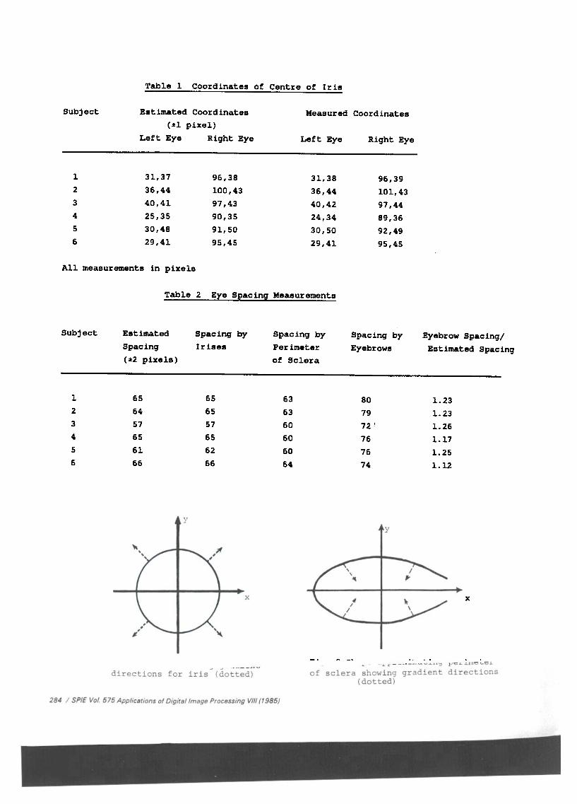
Table 1 Coordinates of Centre of Iris
Subject Estimated Coordinates Measured Coordinates
(~l pixel)Left Eye Right Eye Left Eye Right Eye
1 31,37 96,38 31,38 96,39
2 36,44 100,43 36,44 101,43
3 40,41 97,43 40,42 97,44
4 25,35 90,35 24,34 89,36
5 30,48 91,50 30,50 92,49
6 29,41 95,45 29,41 95,45
All measurements in pixels
Table 2 Eye Spacing Measurements
Subject Estimated Spacing by Spacing by Spacing by Eyebrow Spacing/Spacing Irises Perimeter Eyebrows Estimated Spacing
(~2 pixels) of Sclera
1
2
3
4
5
6
65
64
57
65
61
66
Fig. 1 Circle showing gradientdirections for iris (dotted)
284 / SPIE Vol 575 Applications of Digital Image Processing VIII (1985)
65
65
57
65
62
66
63
63
60
60
60
64
1. 23
1.23
1.26
1.17
1.25
1.12
80
7972 ~
76
76
74
y
x
Fig. 2 Shape approximating perimeterof sclera showing gradient directions
(dotted)

Fig. 4 Gradient image of facegradient strength and direction
Fig. 6 Image of subject 6 showingdetection of perimeter of sclera
Fig. 3 Original image of face
Fig. 5 Image of subject 3 showingdetection of irises
showing
Fig. 7 Image of subject 1 showingdetection of region below eyebrows
Processing VIII (1985) / 285
SPIE Vol. 575 Applications
of Digita//mage