Embed Size (px)
Citation preview

Higher Order MIMO Testing with the R&S®SMW200A Vector Signal Generator Application Note
Products:
| R&SSMW200A
| R&SSGS100A
| R&SSGT100A
Due to its outstanding performance the
R&SSMW200A vector signal generator is
ideal for testing MIMO receivers in a vast
variety of applications offering maximum
usability at minimum form factor. It can
generate up to eight antenna signals
simultaneously in its digital baseband – all
standard-compliant and with antenna-
specific coding. In addition, it can simulate
the complete MIMO transmission channel
with up to 32 fading channels, sufficient to
emulate higher-order MIMO configurations
such as 3x3, 4x4, and 8x4.
This application note explains how to use
the SMW for testing higher order MIMO
systems by presenting different key
applications.
App
licat
ion
Not
e
C. T
röst
er-S
chm
id
01.2
016-
1GP
97_1
E

Table of Contents
1GP97_1E Rohde & Schwarz Higher Order MIMO Testing with the R&S®SMW200A Vector Signal Generator 2
Table of Contents
1 Introductory Note ................................................................... 4
2 Overview ................................................................................. 4
3 MIMO Configurations ............................................................. 7
4 External RF Outputs .............................................................. 9
5 General 2x2 MIMO ................................................................ 10
5.1 SMW System Configuration ......................................................................10
5.1.1 Baseband Source Configuration ..............................................................11
5.1.2 Stream Mapping..........................................................................................12
5.2 Fading Simulation Settings .......................................................................12
5.2.1 MIMO Correlation Matrix ............................................................................14
5.3 AWGN ..........................................................................................................19
5.4 Synchronization..........................................................................................20
5.5 Leveling .......................................................................................................21
6 LTE Advanced Carrier Aggregation with 2x2 MIMO ......... 22
6.1 SMW System Configuration ......................................................................23
6.1.1 Stream Mapping..........................................................................................24
6.1.2 External RF Outputs ...................................................................................25
6.2 LTE Advanced Signal Configuration ........................................................25
6.3 Fading Simulation Settings .......................................................................28
6.4 Synchronization..........................................................................................29
7 Dual Cell HSDPA with 2x2 MIMO ........................................ 30
7.1 SMW System Configuration ......................................................................30
7.2 HSDPA Signal Configuration ....................................................................31
7.3 Fading Simulation Settings .......................................................................32
7.4 Synchronization..........................................................................................33
8 LTE Multiuser MIMO ............................................................. 34
8.1 LTE Test Case Wizard ................................................................................35
8.2 SMW System Configuration ......................................................................35
8.2.1 Stream Mapping..........................................................................................36
8.3 LTE UE Signal Configuration ....................................................................36

Table of Contents
1GP97_1E Rohde & Schwarz Higher Order MIMO Testing with the R&S®SMW200A Vector Signal Generator 3
8.3.1 Setting relative UE Power Levels .............................................................37
8.4 Fading Simulation Settings .......................................................................37
8.5 Synchronization..........................................................................................37
9 WLAN 802.11ac with 3x3 MIMO ........................................... 39
9.1 SMW System Configuration ......................................................................39
9.1.1 Stream Mapping..........................................................................................40
9.1.2 External RF Outputs ...................................................................................40
9.2 WLAN 11ac Signal Configuration .............................................................41
9.3 Fading Simulation Settings .......................................................................42
9.4 Synchronization..........................................................................................42
10 LTE with 4x4 MIMO .............................................................. 43
10.1 SMW System Configuration ......................................................................43
10.1.1 Stream Mapping..........................................................................................44
10.1.2 External RF Outputs ...................................................................................44
10.2 LTE Signal Configuration ..........................................................................45
10.3 Fading Simulation Settings .......................................................................47
10.4 Synchronization..........................................................................................47
11 Summary ............................................................................... 48
12 Abbreviations ....................................................................... 50
13 References ............................................................................ 50
14 Ordering Information ........................................................... 51

Introductory Note
SMW System Configuration
1GP97_1E Rohde & Schwarz Higher Order MIMO Testing with the R&S®SMW200A Vector Signal Generator 4
1 Introductory Note The following abbreviations are used in this application note for Rohde & Schwarz
products:
The R&S®SMW200A vector signal generator is referred to as SMW
The R&S®SGS100A SGMA RF source is referred to as SGS
The R&S®SGT100A SGMA vector RF source is referred to as SGT
Instrument options, e.g. R&S®SMW-K55 are referred to as SMW-K55
The abbreviation SGx denotes either a SGS or a SGT.
2 Overview All modern wireless and mobile radio standards use the multiple input multiple output
(MIMO) technology to increase data rates. For testing MIMO receivers with multiple
receive antennas the SMW is the ideal test instrument. It can generate up to eight
transmit antenna signals simultaneously in its digital baseband. The signals of all
transmit antennas can be set up in one go from a single menu (coupled baseband
sources) – all standard-compliant and with antenna-specific coding. In addition, the
SMW is able to simulate the complete MIMO transmission channel and can thus
generate realistic test signals for MIMO receivers. It supports up to 32 fading channels
sufficient to emulate higher-order MIMO configurations such as 3x3, 4x4, and 8x4. The
maximum fading bandwidth is 160 MHz. The SMW supports up to 8 fading channel at
a fading bandwidth of 160 MHz, up to 16 fading channel at a fading bandwidth of
80 MHz and up to 32 fading channel at a fading bandwidth of 40 MHz1. The SMW
comprises stimulus generation, MIMO channel emulation, and RF signal generation in
a single box. Up to two RF outputs are available on the SMW; up to two additional RF
outputs can be made available by connecting external instruments, such as the SGS
signal generator. For ease of use the external instruments are controlled from the
SMW such that the whole setup acts like a single unit.
1 Please see the SMW data sheet [1] for details.

Overview
SMW System Configuration
1GP97_1E Rohde & Schwarz Higher Order MIMO Testing with the R&S®SMW200A Vector Signal Generator 5
This application note presents some important MIMO applications which are supported
by the SMW. At first, section 3 gives an overview of the various possible MIMO
configurations. Section 4 explains how to connect external instruments to the SMW to
increase the number of available RF outputs. Section 5 presents a general and
detailed introduction on how to configure the SMW for MIMO testing based on the
example of 2x2. The sections 6 to 10 present a specific MIMO application,
respectively. The following table lists the different presented applications. This
application note closes with a summary.
Supported MIMO applications presented in detail
Application Section MIMO configuration Required instruments
LTE Advanced carrier
aggregation with 2x2 MIMO
6 2x 2x2 1 SMW, (2 SGx)2
Dual cell HSDPA with 2x2
MIMO
7 2x 2x2 1 SMW, (2 SGx)2
LTE multiuser MIMO 8 4x 1x2 1 SMW
WLAN 802.11ac with 3x3 MIMO 9 3x3 1 SMW, 1 SGx
LTE with 4x4 MIMO 10 4x4 1 SMW, 2 SGx
SGx denotes either a SGS or a SGT
Beyond these applications the following table lists some further example applications
supported by the SMW (from firmware version 3.20.390.22 onwards).
Supported MIMO applications (not presented in detail)
Application MIMO configuration
LTE downlink with MIMO 8x4
LTE uplink with MIMO 4x8
Interference testing for LTE (wanted and
interfering UE), each UE with MIMO
2x 2x4
Interference testing for WLAN (two
devices/hotspots), each with MIMO
2x 2x4
2x 3x3
2x 4x2
2x 4x4
LTE carrier aggregation (2 component
carriers) with MIMO for each carrier
2x 2x4
2x 4x2
2x 4x4
Dual cell LTE with MIMO for each cell 2x 2x4
2x 4x2
2x 4x4
2 SGx is only needed if the component carrier spacing is so large that the component carriers do not fit into
the internal ±80 MHz I/Q bandwidth of the digital baseband.

Overview
SMW System Configuration
1GP97_1E Rohde & Schwarz Higher Order MIMO Testing with the R&S®SMW200A Vector Signal Generator 6
Please refer to reference [18] for details on these applications.

MIMO Configurations
SMW System Configuration
1GP97_1E Rohde & Schwarz Higher Order MIMO Testing with the R&S®SMW200A Vector Signal Generator 7
3 MIMO Configurations The SMW is ideal for MIMO applications. It supports all important MIMO configurations
such as 2x2, 3x3, 4x4, 8x2 and 8x4. Whenever more than two RF signals are required
external instruments such as the SGS can be connected (see section 4 for details).
The SMW introduces the concept of “entities”. An entity can be e.g. a carrier, a cell or a
user. The SMW can simulate MIMO fading for up to two entities in parallel which
makes it possible to support also complex applications such as LTE Advanced carrier
aggregation and dual cell HSDPA.
The following tables give an overview of the different MIMO configurations that can be
implemented with the SMW. (See reference [1] and section 11 for required options).
Overview MIMO configurations
One entity
MIMO configuration Required instruments Supported RF bandwidth
1x2 1 SMW 160 MHz
1x3 1 SMW, 1 SGx 160 MHz
1x4 1 SMW, 2 SGx 160 MHz
1x8 1 SMW, 6 SGT 80 MHz
2x1 1 SMW 160 MHz
2x2 (See section 5) 1 SMW 160 MHz
2x3 1 SMW, 1 SGx 160 MHz
2x4 1 SMW, 2 SGx 160 MHz
2x8 1 SMW, 6 SGT 80 MHz
3x1 1 SMW 160 MHz
3x2 1 SMW 160 MHz
3x3 (See section 9) 1 SMW, 1 SGx 80 MHz
3x4 1 SMW, 2 SGx 80 MHz
4x1 1 SMW 160 MHz
4x2 (See section 8) 1 SMW 160 MHz
4x3 1 SMW, 1 SGx 80 MHz
4x4 (See section 10) 1 SMW, 2 SGx 80 MHz
4x8 1 SMW, 6 SGT 40 MHz
8x1 1 SMW 80 MHz
8x2 1 SMW 80 MHz
8x4 1 SMW, 2 SGx 40 MHz

MIMO Configurations
SMW System Configuration
1GP97_1E Rohde & Schwarz Higher Order MIMO Testing with the R&S®SMW200A Vector Signal Generator 8
Overview MIMO configurations
Two entities
MIMO configuration Required instruments Supported RF bandwidth
2x 1x2 1 SMW, (2 SGx)3 160 MHz
2x 1x3 1 SMW, 1 SGx, (3 SGT)3 80 MHz
2x 1x4 1 SMW, 2 SGx, (4 SGT)3 80 MHz
2x 2x1 1 SMW 160 MHz
2x 2x2 (See section 6) 1 SMW, (2 SGx)3 160 MHz
2x 2x3 1 SMW, 1 SGx, (3 SGT)3 80 MHz
2x 2x4 1 SMW, 2 SGx, (4 SGT)3 80 MHz
2x 3x1 1 SMW 80 MHz
2x 3x2 1 SMW, (2 SGx)3 80 MHz
2x 3x3 1 SMW, 1 SGx, (3 SGT)3 40 MHz
2x 3x4 1 SMW, 2 SGx, (4 SGT)3 40 MHz
2x 4x1 1 SMW 80 MHz
2x 4x2 1 SMW, (2 SGx)3 80 MHz
2x 4x3 1 SMW, 1 SGx, (3 SGT)3 40 MHz
2x 4x4 1 SMW, 2 SGx, (4 SGT)3 40 MHz
The different MIMO configurations can be set via the system configuration menu. The
user has the choice to use the resulting internal signal routing with or without fading
simulation (in both cases same options are required).
3 It depends on the application if additional external RF outputs (SGS/SGT) are required.

External RF Outputs
SMW System Configuration
1GP97_1E Rohde & Schwarz Higher Order MIMO Testing with the R&S®SMW200A Vector Signal Generator 9
4 External RF Outputs The SMW offers up to two RF outputs. To increase the number of available RF outputs
beyond two, external instruments such as the SGS or the SGT can be connected to
the SMW. The SGx is ideal for this task as it is small, cost-efficient and offers
outstanding signal quality. Although it is the perfect match for the SMW, other RF
vector signal generators from Rohde & Schwarz can be used as well for upconverting
the SMW’s analog I/Q baseband signals to the RF. An example setup with two SGxs
looks as follows:
REF OUT
REF IN
I/Q USB I/Q USB
I/Q signal
Control (USB / LAN)
10 MHz reference frequency
RF outputs DC
REF OUT REF IN
RF outputs BA
Per SGx there are three connections needed:
The I/Q output signals of the SMW are connected to the I/Q inputs of the SGx.
The 10 MHz reference frequency of the SMW is connected to the SGx for
frequency synchronization.
A control line, either via USB or LAN, connects the SGx to the SMW for
automatic remote control of the SGx
Use cables of the same type that are exactly equal in length to feed the analog I/Q
signals to the SGS. This is important, since otherwise a delay between the I and the Q
signal is introduced, which can degrade signal quality significantly. Also, use high
quality adapters and do not accumulate adapters.
Use the R&S®SMU-Z6 digital cable (accessory) to feed the digital I/Q signal to the
SGT.
The external SGx can be controlled directly from the SMW. This is a great benefit for
the user since the whole setup consisting of one SMW and up to two SGSs or up to six
SGTs behaves like a single unit. The settings for the SGxs are made on the SMW.
They are automatically transferred to the connected SGx via the control line.
Please see reference [17] for how to connect and control the SGx. The procedure is
straightforward and the handling of the external instruments is fast and easy.

General 2x2 MIMO
SMW System Configuration
1GP97_1E Rohde & Schwarz Higher Order MIMO Testing with the R&S®SMW200A Vector Signal Generator 10
5 General 2x2 MIMO A 2x2 MIMO test setup consists of two transmit signals and two receive antennas at
the DUT. This MIMO configuration involves four fading channels (AA, AB, BA, and BB).
DUT
SMW
Fading simulationTx signals
Tx 1
Tx 2
Rx 1
Rx 2
AA
AB
BA
BB
5.1 SMW System Configuration
To open the system configuration menu, press the “Fading A” button and select
“System Configuration” from the list.
→
In the “Fading/Baseband Config” tab make the following settings:
Press the “Apply” button to actually apply the settings. The resulting signal routing is
shown in the block diagram.
Baseband A generates the first, baseband B the second transmit (Tx) signal. The
internal real-time fading simulators simulate the four fading channels. The resulting
streams A and B correspond to the signals at the following points in the block diagram:

General 2x2 MIMO
SMW System Configuration
1GP97_1E Rohde & Schwarz Higher Order MIMO Testing with the R&S®SMW200A Vector Signal Generator 11
Stream A
Stream B
5.1.1 Baseband Source Configuration
The SMW offers two modes for the configuration of the baseband section. The user
can chose between separate and coupled baseband sources:
Especially for MIMO scenarios, coupled sources make the configuration quick and
easy. The user just needs to configure the wanted settings once. The configuration of
the second baseband is eliminated.
The SMW offers the baseband coupling feature for the MIMO supporting digital
standards LTE and WLAN.

General 2x2 MIMO
Fading Simulation Settings
1GP97_1E Rohde & Schwarz Higher Order MIMO Testing with the R&S®SMW200A Vector Signal Generator 12
5.1.2 Stream Mapping
The following menu is used to map the I/Q streams of the digital baseband section to
the various outputs (RF, analog, digital) of the SMW.
To route the streams A and B to the RF outputs A and B respectively, make the
following settings in the “I/Q Stream Mapper” tab:
5.2 Fading Simulation Settings
Terminology:
Fading channel:
2x2 MIMO has four fading channels (AA, AB, BA, BB) between the transmit
and receive antennas.
Fading path:
Each fading channel can consist of several fading paths (i.e. fading taps). The
number of fading paths within one fading channel can be configured.
To open the fading menu, press the “Fading” button and select “Fading Settings” from
the list.
→
In the “General” tab the user can chose various predefined settings that are in
accordance with test scenarios stipulated in modern mobile radio standards. For
example, fading scenarios for LTE are supported, including the specified correlation
(high, medium, low) between the fading channels. All fading settings are automatically
configured in accordance with the selected fading scenario.

General 2x2 MIMO
Fading Simulation Settings
1GP97_1E Rohde & Schwarz Higher Order MIMO Testing with the R&S®SMW200A Vector Signal Generator 13
The selected fading scenario is shown graphically as power delay profile in the “Path
Graph” tab.

General 2x2 MIMO
Fading Simulation Settings
1GP97_1E Rohde & Schwarz Higher Order MIMO Testing with the R&S®SMW200A Vector Signal Generator 14
Instead of selecting a predefined fading scenario, the user can also configure a custom
scenario. In the “Path Table” tab, the user can specify the number of active fading
paths, their delay and attenuation, the fading profile to be used (e.g. Rayleigh), as well
as all path related settings.
5.2.1 MIMO Correlation Matrix
To test MIMO receivers under real-world conditions, a certain degree of correlation
between the fading channels has to be simulated. The correlation is quantified in terms
of a matrix. For 2x2 MIMO this correlation matrix is a 4x4 matrix representing the
correlation of the four fading channels (AA, AB, BA, BB).
AA AB BA BB
AA
AB
BA
BBCorrelation coefficients
The correlation between two fading channels is defined by a correlation coefficient that
is a measure for the similarity of the two signals. The correlation coefficient is a
complex quantity expressed as a pair of numbers in either Cartesian form (real-
imaginary) or polar form (magnitude-phase). The polar form is more descriptive, since
it directly gives the magnitude and phase relationship of the two signals.
In the path table, press on “Matrix” to open the correlation matrix menu. Note that a correlation matrix applies to the selected fading path only. Each path has its own correlation matrix that can be defined individually. The matrix of one fading path can also be copied to other fading paths.

General 2x2 MIMO
Fading Simulation Settings
1GP97_1E Rohde & Schwarz Higher Order MIMO Testing with the R&S®SMW200A Vector Signal Generator 15
Perfect correlation is achieved when magnitude = 1 and phase = 0, whereas
magnitude = 0.00 (and phase = 0)4 gives absolutely no correlation. To simulate ideal
conditions for MIMO, i.e. no correlation between the fading channels, set all correlation
coefficients to zero (default setting) except for the diagonal matrix elements. They
represent the correlation of one fading channel with itself and are therefore usually set
to magnitude = 1 (see reference [16] for more information on the diagonal elements
and their special use). To create real-world conditions, set the off-diagonal elements to
nonzero values to simulate a certain degree of correlation between the fading
channels.
The following figure illustrates graphically the effect of nonzero magnitude and phase
values. Five example correlation coefficients and the corresponding correlations
between two test signals are shown. In simple terms, the more the values differ from
magnitude = 0, the higher the correlation is and hence the less efficient the MIMO
system is.
4 If magnitude = 0, it is common practice to define phase = 0, although the phase is not a definite value in
this case. It could be any arbitrary real value.

General 2x2 MIMO
Fading Simulation Settings
1GP97_1E Rohde & Schwarz Higher Order MIMO Testing with the R&S®SMW200A Vector Signal Generator 16
Magnitude = 1, phase = 0
Equal amplitudes
Zero phase shift
Perfect correlation
Magnitude = 0, phase = 0
Unequal amplitudes
Zero correlation
Signal 1
Signal 2
Magnitude = 1, phase = 0
Unequal amplitudes
Phase shift
Magnitude = 1, phase = 0
Unequal amplitudes
Zero phase shift
Magnitude = 1, phase = 0
Equal amplitudes
Phase shift
-1
-1
1
1
Imaginary
RealM
agni
tude
Phase
The user can choose between three ways to configure the correlation matrix:
“Individual” mode, “Kronecker” mode, and “AoA / AoD” mode (angle of arrival / angle of
departure).
Individual mode:
In this mode, the user can set the correlation coefficients directly. Only the matrix
elements marked in orange in above screenshot need to be set, as they already fully
describe the correlations among the four fading channels. The remaining off-diagonal
matrix elements are determined automatically by exploiting the complex conjugate
symmetry across the diagonal. For example, matrix element [BB,AB] describes the
correlation between channels AB and BB. This correlation is also described by matrix
element [AB,BB]. Thus, the values entered into matrix element [BB,AB] define the
values of matrix element [AB,BB] and vice versa.
Kronecker mode:
This mode is based on the Kronecker assumption of separable transmit and receive
correlations, i.e. the correlation between the Rx antennas is assumed to be
independent from the correlation between the Tx antennas. The Kronecker mode
simplifies the configuration of the matrix. The user can specify transmitter (Tx) and
receiver (Rx) correlation coefficients. Based on these all matrix elements are
automatically calculated and displayed. The Tx correlation coefficient correlates path
AA with BA and path AB with BB, i.e. the two transmitter signals Tx1 and Tx2 are
faded in a correlated way. Accordingly, the Rx correlation coefficient correlates path
AA with AB and path BA with BB, i.e. the two receiver signals Rx1 and Rx2 are faded
in a correlated way.

General 2x2 MIMO
Fading Simulation Settings
1GP97_1E Rohde & Schwarz Higher Order MIMO Testing with the R&S®SMW200A Vector Signal Generator 17
For example, a Tx correlation coefficient of 1 (magnitude) means perfect correlation of
the two transmitter signals. This case is shown in the following figure. The left side of
the figure shows the signal at the first receive antenna (Rx1), while the right side of the
figure shows the signal at the second receive antenna (Rx2). The shown spectra are
snapshots of the Rx signals, both measured at the same point in time. In order to
distinguish the two transmit signals Tx1 and Tx2 in the spectrum, a frequency offset of
10 MHz has been applied to Tx2.5 The figure shows that the two transmit signals are
faded in a perfectly correlated way, while the two receive signals differ (because the Rx
correlation coefficient is set to 0).
For example, to simulate perfect Rx signal correlation and no Tx signal correlation, set
the Rx correlation coefficient to 1 (magnitude) and the Tx correlation coefficient to 0
(magnitude). This case is shown in the following figure. Now, Tx1 and Tx2 are faded
independently, while the Rx signals are perfectly correlated.
5 In MIMO applications the two Tx signals are always transmitted at the same center frequency. The
frequency offset is merely applied for demonstration purposes.

General 2x2 MIMO
Fading Simulation Settings
1GP97_1E Rohde & Schwarz Higher Order MIMO Testing with the R&S®SMW200A Vector Signal Generator 18
AoA /AoD mode:
This mode is based on the spatial channel model (SCM). In contrast to analytical
channel models like the Kronecker model which derive the MIMO matrix without any
consideration of propagation parameters, the SCM is a stochastic physical model
which uses physical propagation parameters (e.g. AoD, AoA, number of propagation
paths, path delay, path power) and their statistical behavior to derive the MIMO matrix
[14]. Also in the SCM, the number of propagation paths, path delay, and path power
can be reproduced by a power delay profile. Each propagation path is characterized by
a AoD, AoA and respective angular spread. These parameters remain fixed for the
respective path, i.e. are not time-variant. The number and configuration of the
antennas at the transmitter and the receiver is also considered in the model. See
reference [3] for details on SCM.
Tx antenna
array
Rx antenna
array
Cluster of scatterers
Cluster
LOS
AoD
AoD
AoA
AoA
AoD
spread
Array broadside
AoA
spread
Power delay profile
P
t
In the SMW, the user can specify the AoD, AoA and the corresponding angular
spreads for each fading path of the power delay profile. The angular spectrum can be
set to follow a uniform, Gaussian, or Laplacian distribution. It is sufficient to configure
one “ray” per fading path (although the GUI allows configuring up to four “rays” per
fading path). In addition, the antenna distance at transmitter and receiver side can be
set. Based on these setting the MIMO correlation matrix is calculated, i.e. all matrix
elements are automatically calculated and displayed.

General 2x2 MIMO
AWGN
1GP97_1E Rohde & Schwarz Higher Order MIMO Testing with the R&S®SMW200A Vector Signal Generator 19
-15.69
-15.69
15.69 15.69
15.69
-15.69
-344.31
344.31
5.3 AWGN
The SMW can superimpose noise on the baseband I/Q streams. An additive white
Gaussian noise (AWGN) signal with selectable system bandwidth can be added to the
streams after fading simulation. For example, the AWGN signal can be used for
simulating a certain signal-to-noise ratio at the receiver to test the receiver sensitivity.
Stream A
Stream B
AWGN
It is possible to specify the AWGN independently for each stream. If the “Coupled
Mode” parameter is enabled, the same AWGN settings are used for each stream. In
any case, the AWGN is statistically independent for each stream.

General 2x2 MIMO
Synchronization
1GP97_1E Rohde & Schwarz Higher Order MIMO Testing with the R&S®SMW200A Vector Signal Generator 20
5.4 Synchronization
For MIMO it is essential that baseband A and B start simultaneously. This is assured in
the SMW for the 2x2 system configuration as well as for any other MIMO system
configuration (“Advanced” mode). Either an internal or an external trigger signal can be
used to start the basebands.
When using coupled baseband sources synchronization is assured automatically.
When using separate baseband sources the trigger settings of baseband B are
automatically adjusted to achieve synchronization: baseband B is triggered by
baseband A.
The fading simulators run by default in “Auto” mode. If this mode is used, a (re)start of
the basebands cause an automatic (re)start of the fading statistics. At a restart, the
simulated fading processes start from the beginning with the same statistics as
previously, thus reproducing the exact same fading conditions for testing under
repeatable conditions.
General 2x2 MIMO
Leveling
1GP97_1E Rohde & Schwarz Higher Order MIMO Testing with the R&S®SMW200A Vector Signal Generator 21
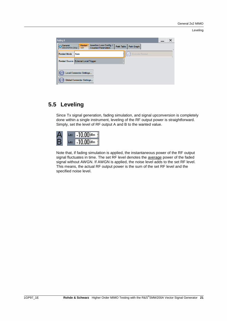
5.5 Leveling
Since Tx signal generation, fading simulation, and signal upconversion is completely
done within a single instrument, leveling of the RF output power is straightforward.
Simply, set the level of RF output A and B to the wanted value.
Note that, if fading simulation is applied, the instantaneous power of the RF output
signal fluctuates in time. The set RF level denotes the average power of the faded
signal without AWGN. If AWGN is applied, the noise level adds to the set RF level.
This means, the actual RF output power is the sum of the set RF level and the
specified noise level.

LTE Advanced Carrier Aggregation with 2x2 MIMO
1GP97_1E Rohde & Schwarz Higher Order MIMO Testing with the R&S®SMW200A Vector Signal Generator 22
6 LTE Advanced Carrier Aggregation with 2x2 MIMO In LTE Advanced (LTE-A), multiple carriers can be aggregated to increase
transmission bandwidth and thus peak data rates. Although up to five component
carriers (CC) can be aggregated, initial LTE Advanced (3GPP Release 10)
deployments will use a maximum of two component carriers. In the frequency domain,
the carriers can be placed in the same frequency band (intra-band) as well as in
different frequency bands (inter-band). For intra-band carrier aggregation, contiguous
and non-contiguous placement is possible.
Please see reference [4] for comprehensive information on LTE-A.
LTE-A carrier aggregation with two CCs and 2x2 MIMO involves two transmit antenna
signals, each consisting of two CCs. Each CC shall be faded independently.
In the SMW, each CC is generated by an individual baseband source to achieve
independent fading for each CC. This means, the four fading channels of 2x2 MIMO
double: in total, eight independent fading channels need to be simulated – a challenge,
but feasible with a single SMW.

LTE Advanced Carrier Aggregation with 2x2 MIMO
SMW System Configuration
1GP97_1E Rohde & Schwarz Higher Order MIMO Testing with the R&S®SMW200A Vector Signal Generator 23
SMW
Fading simulation1st CC
Fading simulation2nd CC
+
DUT
+
Tx 1
Tx 2
Tx 1
Tx 2
Rx 1
Rx 2
6.1 SMW System Configuration
Open the system configuration menu. In the “Fading/Baseband Config” tab make the
following settings:
Press the “Apply” button to actually apply the settings. The resulting signal routing is
shown in the block diagram.
Entity 1 generates the first, entity 2 the second component carrier. Each CC is subject
to real-time 2x2 MIMO fading.

LTE Advanced Carrier Aggregation with 2x2 MIMO
SMW System Configuration
1GP97_1E Rohde & Schwarz Higher Order MIMO Testing with the R&S®SMW200A Vector Signal Generator 24
6.1.1 Stream Mapping
The resulting streams A and B correspond to the first CC. Streams C and D
correspond to the second CC. To form the wanted LTE-A signal the component
carriers need to be combined. The two CCs can be combined in two ways:
Internal addition for intra-band carrier aggregation:
The SMW adds the streams internally. Outputs RF A and RF B are used to
feed the signals to the two receive antennas of the DUT.
This method can be applied, if the two CCs fit into the ±80 MHz I/Q signal
bandwidth of the digital baseband section.
External addition for inter-band carrier aggregation:
The streams are separately upconverted to the RF. This is achieved with two
additional external RF outputs (e.g. from two SGxs). The RF signals are then
added with external RF combiners. The combined signals are fed to the two
receive antennas of the DUT.
Internal Addition in the Baseband
To add streams A and C, map both streams to RF output A. To add streams B and D,
map both streams to RF output B. Make the following settings in the “I/Q Stream
Mapper” tab:
Apply a frequency offset for streams C and D. This frequency offset has to be identical
for streams C and D and determines the spacing of the two component carriers.
To achieve a large CC spacing, use in addition a negative frequency offset for streams
A and B.
External Addition in the RF
To upconvert streams A, B, C, and D separately to the RF, map streams A and B to
the RF outputs A and B and streams C and D to the analog I/Q outputs 1 and 2. Make
the following settings in the “I/Q Stream Mapper” tab:

LTE Advanced Carrier Aggregation with 2x2 MIMO
LTE Advanced Signal Configuration
1GP97_1E Rohde & Schwarz Higher Order MIMO Testing with the R&S®SMW200A Vector Signal Generator 25
6.1.2 External RF Outputs
Note that this section applies only for external signal addition. Skip this section if you
use internal signal addition.
Two SGxs are used as I/Q upconverters to increase the number of available RF
outputs from two to four. Connect the I/Q output signals of the SMW to the two SGxs.
Add RF signals A and C by means of an external RF combiner. Add RF signals B and
D by means of a second external RF combiner.
RF C
RF A
RF D
RF B
+
+
DUT
The SGxs are controlled directly from the SMW. The settings for the SGx are made in
the “External RF and I/Q” tab and are automatically transferred to the connected SGx
via the control line. See section 4 for details. Set the RF frequency of the SGx such
that there is a frequency offset for signals RF C and D with respect to signals RF A and
B. This frequency offset has to be identical for both SGxs and determines the spacing
of the two component carriers.
6.2 LTE Advanced Signal Configuration
Since coupled baseband sources are used for this application, the basebands are
configured all at once from a common menu.

LTE Advanced Carrier Aggregation with 2x2 MIMO
LTE Advanced Signal Configuration
1GP97_1E Rohde & Schwarz Higher Order MIMO Testing with the R&S®SMW200A Vector Signal Generator 26
Touch the “General DL Settings” button. In the “CA” tab of the “General DL Settings”
menu, carrier aggregation is already activated per default with two CCs. In this
example, the first CC has the “Cell Index” 0 and the second CC has the “Cell Index” 3
(selected arbitrarily). To achieve cross-carrier scheduling, the “schedCell Index”
parameter is set to “0” for both CCs, i.e. both CCs are scheduled by the CC that has
“Cell Index” 0.
Change to the “Scheduling” tab and set the “PDSCH Scheduling” parameter to
“Auto/DCI”. In this mode, the PDSCH allocations are configured automatically and
standard-conform according to the selected PDCCH DCIs (see further down).
Change to the “Antenna Ports” tab. The “Global MIMO Configuration” parameter is
preset to “2 TxAntennas” corresponding to 2x2 spatial multiplexing. The table
illustrates the applied mapping of the four basebands (BB A to BB D) to the antenna
ports (AP 0 and AP 1).

LTE Advanced Carrier Aggregation with 2x2 MIMO
LTE Advanced Signal Configuration
1GP97_1E Rohde & Schwarz Higher Order MIMO Testing with the R&S®SMW200A Vector Signal Generator 27
Basebands A and B generate the first CC (with “Cell Index” 0). Basebands C and D
generate the second CC (with “Cell Index” 3).
Basebands A and C are mapped to antenna port 0, basebands B and D to antenna
port 1, i.e. baseband A and C generate the first antenna signal, baseband B the
second antenna signal. Each antenna signal includes automatically the appropriate
downlink reference signal as well as all other antenna-specific properties.
In the LTE main menu, touch the “Frame Configuration” button. In the “General” tab of
the “Frame Configuration” menu, the user can set the number of subframes that he
wants to configure via the “No of Configurable Subframes” parameter. If wanted, the
user can select a specific transmission mode for the “User 1” to “User 4”. This step can
principally be omitted, but it may help users who want to have certainty that their made
settings are according to a specific transmission mode.
Change to the “PDCCH” tab and add a second row to the DCI table by touching the
“Append” button. In this example, the “Cell Index” parameter is set to “0” in both rows,
because this is the cell index of the scheduling CC (see “CA” tab of the “General DL
Settings” menu). In both rows, set the “DCI Format” to “2” or “2A” for the selected
“User” (e.g. “User1”). DCI formats 2 and 2A are used for closed loop and open loop
spatial multiplexing, respectively.

LTE Advanced Carrier Aggregation with 2x2 MIMO
Fading Simulation Settings
1GP97_1E Rohde & Schwarz Higher Order MIMO Testing with the R&S®SMW200A Vector Signal Generator 28
In the first row, touch “Config…” to open the “DCI Format Configuration” menu. Set the
“Carrier Indicator Field” to “0”, because this is the cell index of the first CC. All settings
made in the “DCI Format Configuration” menu correspond now to this CC. Optionally,
configure the content by editing e.g. the “Resource Block Assignment”, “Modulation
and Coding Scheme”, and “Precoding Information” parameters as wanted.
Go back to the “PDCCH” tab and touch “Config…” in the second row of the DCI table.
In the “DCI Format Configuration” menu, set the “Carrier Indicator Field” to “3”,
because this is the cell index of the second CC in this example. All settings made in
the menu correspond to the second CC. Optionally, configure the content for this CC.
The PDCCH Configuration applies to the selected subframe only (“Subframe
Selection” parameter). Therefore, configure the DCI format and the content for every
configurable subframe.
Please see reference [15] or the SMW online help for comprehensive information on
the LTE setting parameters mentioned in this section.
6.3 Fading Simulation Settings
Since two independent fading entities are used for this application, both fading entities
need to be configured individually. This is however straightforward when using a
predefined fading scenario.
In the “General” tab of the fading menu the user can chose from various predefined
MIMO settings for LTE. The standard-compliant fading scenarios include also the
specified correlation (high, medium, low) between the fading channels. All fading
settings are automatically configured in accordance with the selected MIMO scenario.
Set the same fading scenario in both fading entities.

LTE Advanced Carrier Aggregation with 2x2 MIMO
Synchronization
1GP97_1E Rohde & Schwarz Higher Order MIMO Testing with the R&S®SMW200A Vector Signal Generator 29
Besides selecting a predefined fading scenario, the user can also configure a custom
scenario if needed (see section 5.2 for details). To set the same fading scenario in both
fading entities, save the settings of the first entity and recall them in the second entity.
Note that although the same fading scenario is used in both fading entities, the fading
process is statistically independent for each entity.
6.4 Synchronization
The coupling of the baseband sources guarantees their synchronization.
The fading simulators can be run in “Auto” mode. In this mode, a (re)start of the
baseband cause an automatic (re)start of the fading statistics. The two fading
simulators are thus indirectly synchronized via the baseband. Turn on fading simulation
before turning on the baseband.

Dual Cell HSDPA with 2x2 MIMO
SMW System Configuration
1GP97_1E Rohde & Schwarz Higher Order MIMO Testing with the R&S®SMW200A Vector Signal Generator 30
7 Dual Cell HSDPA with 2x2 MIMO Dual Cell (DC) HSDPA is an evolution of HSPA defined to increase transmission
bandwidth and thus peak data rates by means of carrier aggregation in the downlink.
DC-HSPA is defined in the 3GPP specification Release 8. From Release 9 onwards it
is possible to combine DC-HSPA with MIMO. Release 9 also introduces dual band
operation for DC-HSPA, i.e. the two carriers need no longer to be adjacent in the
frequency domain but can be in two different frequency bands. Please see reference
[5] for comprehensive information on HSPA.
Dual Cell HSDPA involves two different cells. Each cell shall use 2x2 MIMO
transmissions. This gives four signals that shall be faded independently.
In the SMW, each of the four signals is generated by an individual baseband source.
Since MIMO is used on both cells, eight independent fading channels need to be
simulated, which can be done with a single SMW.
SMW
Fading simulation1st cell
Fading simulation2nd cell
+
DUT
+
Tx 1
Tx 2
Tx 1
Tx 2
Rx 1
Rx 2
7.1 SMW System Configuration
The system configuration is basically identical to the application described in section 6.
Please refer to this section for details. The only exception is that for dual cell HSDPA
separate baseband sources are used.

Dual Cell HSDPA with 2x2 MIMO
HSDPA Signal Configuration
1GP97_1E Rohde & Schwarz Higher Order MIMO Testing with the R&S®SMW200A Vector Signal Generator 31
7.2 HSDPA Signal Configuration
Since separate baseband sources are used for this application, each baseband needs
to be configured individually.
Start with configuring the first cell, i.e. basebands A and B. Set up baseband A to
generate the transmit signal of the first antenna: set the “Diversity/MIMO” parameter to
“Antenna 1 Of 2” in the “Common” tab of the selected base station, e.g. BS1. Disable
the parameter “Open Loop Transmit Diversity”.
To set up channels with channel coding and MIMO pre-coding proceed as follows. In
the “Channel Table” tab, select the “Channel Type” “HS-SCCH” and touch “Config…”
to open the “Enhanced HSDPA Mode” menu. Set the “HSDPA-Mode” parameter to “H-
Set”. The user can choose from predefined H-Sets, e.g. choose the H-Set “9
(16QAM/QPSK)”. Make sure that the “HS-SCCH Type” parameter is set to “Type 3
(MIMO)”. In addition to a HSDPA H-Set, enable the following channels: P-CPICH, P-
CCPCH, P-SCH, S-SCH, PICH.

Dual Cell HSDPA with 2x2 MIMO
Fading Simulation Settings
1GP97_1E Rohde & Schwarz Higher Order MIMO Testing with the R&S®SMW200A Vector Signal Generator 32
Configure the signal of baseband A as wanted. Afterwards continue with setting up
baseband B to generate the transmit signal of the second antenna. Baseband B uses
basically the same settings as baseband A. Therefore, save the settings of baseband
A and recall them for baseband B. The only setting that needs to be adjusted in
baseband B is the “Diversity/MIMO” parameter. Set it to “Antenna 2 Of 2” in the
“Common” tab of the selected base station.
Please see also reference [6] for additional information on HSDPA MIMO operation.
Continue now with configuring the second cell, i.e. basebands C and D. Start with the
settings required for MIMO operation: Set up baseband C and D to generate the
transmit signals of the first and second antenna, respectively. For this, recall the
settings of baseband A in both basebands. In baseband D, adjusted the
“Diversity/MIMO” parameter to “Antenna 2 Of 2”. The next step is to make the settings
required for dual cell operation: Disable the channels P-CCPCH, P-SCH, S-SCH, and
PICH in both basebands, because they are transmitted only by the first cell (serving
cell).
Please see references [6], [7], and [8] for additional information on dual cell HSDPA
operation.
7.3 Fading Simulation Settings
Since two independent fading entities are used for this application, both fading entities
need to be configured individually. This is however straightforward when using a
predefined fading scenario.

Dual Cell HSDPA with 2x2 MIMO
Synchronization
1GP97_1E Rohde & Schwarz Higher Order MIMO Testing with the R&S®SMW200A Vector Signal Generator 33
In the “General” tab of the fading menu the user can chose from various predefined
settings for 3GPP. All fading settings are automatically configured in accordance with
the selected fading scenario. Set the same fading scenario in both fading entities.
The user can specify a correlation between the fading channels by configuring the
MIMO correlation matrix (see section 5.2 for details). The user has also the possibility
to configure a custom scenario if desired. To set the same fading scenario in both
fading entities, save the settings of the first entity and recall them in the second entity.
Note that although the same fading scenario is used in both fading entities, the fading
process is statistically independent for each entity.
7.4 Synchronization
It is assured that all four basebands start simultaneously. Baseband A triggers the
other three basebands B, C, and D. The required trigger settings in basebands B, C,
and D are automatically set.
The fading simulators can be run in “Auto” mode. In this mode, a (re)start of the
basebands cause an automatic (re)start of the fading statistics. The two fading
simulators are thus indirectly synchronized via the basebands. Turn on fading
simulation before triggering the basebands.

LTE Multiuser MIMO
Synchronization
1GP97_1E Rohde & Schwarz Higher Order MIMO Testing with the R&S®SMW200A Vector Signal Generator 34
8 LTE Multiuser MIMO The concept of multiuser MIMO (MU-MIMO) is that a base station communicates
simultaneously with multiple users which share the same radio channel. MU-MIMO
increases the overall network capacity by deploying multi-antenna base stations and
multiple single-antenna mobile users. For initial commercial LTE deployment two
antennas at the base station and one antenna at the UE is the standard case.
User 2
User 3
Base
station
User 1
LTE uses MU-MIMO in the uplink. For example the LTE performance test case 8.3.3
“ACK missed detection for multi-user PUCCH format 1a” defined in the 3GPP technical
specification 36.141 (Release 8) shall verify the base station receiver’s ability to detect
ACK on the wanted signal in the presence of interfering signals under multipath fading
propagation conditions. This test involves four different users – a wanted and three
interfering UEs – transmitting their signals to a base station (DUT). Each UE has one
transmit antenna. The base station receives the four signal streams via two receive
antennas. In the SMW, this scenario can be implemented using a 4x2 MIMO configuration. The whole test setup consists of only a single SMW. It is able to generate all four UE signals and to simulate the required eight fading channels.
SMW
Fading simulationTx signals
UE 1
UE 2
UE 3
UE 4
DUT
Rx 1
Rx 2

LTE Multiuser MIMO
LTE Test Case Wizard
1GP97_1E Rohde & Schwarz Higher Order MIMO Testing with the R&S®SMW200A Vector Signal Generator 35
8.1 LTE Test Case Wizard
To set up the LTE performance test case 8.3.3, the user can use the LTE test case
wizard.
The wizard configures the SMW in line with test cases in the 3GPP technical
specification 36.141 (Release 8). The user can simply select the desired test case and
the wizard sets the system configuration, baseband signals, fading simulation and
AWGN signals – automatically and standard-compliant. The test case wizard is part of
the SMW-K55 LTE option and makes the configuration of the SMW fast and simple.
Please see also reference [2] for additional information on the LTE test case wizard.
For a deeper understanding, the following sections describe how the test case wizard
sets up the SMW for the LTE test case 8.3.3 “ACK missed detection for multi-user
PUCCH format 1a”.
8.2 SMW System Configuration
In the “Fading/Baseband Config” tab of the system configuration menu, the wizard
makes the following settings:

LTE Multiuser MIMO
LTE UE Signal Configuration
1GP97_1E Rohde & Schwarz Higher Order MIMO Testing with the R&S®SMW200A Vector Signal Generator 36
The resulting signal routing is shown in the block diagram.
For MU-MIMO, separate baseband sources are used. Baseband A generates the first,
baseband B the second, baseband C the third and baseband D the fourth UE signal.
The internal real-time faders simulate the eight fading channels AA, AB, BA, BB, CA,
CB, DA, and DB.
8.2.1 Stream Mapping
To route the resulting streams A and B to the RF outputs A and B respectively, the
wizard makes the following settings in the “I/Q Stream Mapper” tab:
8.3 LTE UE Signal Configuration
Since separate baseband sources are used for this application, each baseband is
configured individually by the wizard.
The signals of the wanted UE and the three interfering UEs are set up in line with the
technical specification:
PUCCH channel with format 1a
Normal cyclic prefix
Cell ID is 150
Parameter “Delta shift” is 2
Parameter “N(1)_cs” is 0
ACK/NACK pattern is 1

LTE Multiuser MIMO
Fading Simulation Settings
1GP97_1E Rohde & Schwarz Higher Order MIMO Testing with the R&S®SMW200A Vector Signal Generator 37
Parameter “n_PUCCH” is 2 (wanted UE), 1 (interferer 1), 7 (interferer 2), 14
(interferer 3)
Interferer power levels relative to wanted UE are 0 dB (interferer 1), -3 dB
(interferer 2), 3 dB (interferer 3)
To reproduce the interferer power levels as stipulated in the test case, the baseband
signals need to be leveled relative to each other. The wizard uses the baseband
offsets to achieve this. See section 8.3.1.
8.3.1 Setting relative UE Power Levels
To obtain different UE power levels, the baseband signals can be leveled relative to
each other using the baseband offsets. Click on any “Baseband” block and select
“Baseband Offsets” from the list. In the “Baseband Offsets” menu, the user can set the
parameter “Path Gain” for each baseband signal. For example, if -3 dB is set for
baseband C and +3 dB is set for baseband D, the level of baseband D is 6 dB lower
than that of baseband C.
→
The baseband offsets can therefore be used to set different UE power levels. The set
power offsets (i.e. path gains) apply even if an advanced MIMO routing is in use.6
8.4 Fading Simulation Settings
The SMW supports various predefined settings for LTE. All fading settings are
automatically configured in accordance with the selected scenario.
The performance test case 8.3.3 specifies the use of the “ETU70” propagation
conditions for all four UE signals. The LTE test case wizard simply sets the “ETU
70Hz” predefined scenario.
8.5 Synchronization
In general, when using an advanced MIMO routing it is assured that all four basebands
start simultaneously. Baseband A triggers the other three basebands B, C, and D. The
required trigger settings in basebands B, C, and D are automatically set.
6 This is different to the predecessor instrument R&S
®SMU200A and improves usability.

LTE Multiuser MIMO
Synchronization
1GP97_1E Rohde & Schwarz Higher Order MIMO Testing with the R&S®SMW200A Vector Signal Generator 38
For the performance test case 8.3.3, the basebands are triggered by an external
trigger signal that is provided by the base station. The wizard adjusts the trigger
settings of baseband A automatically as follows:
Baseband A:
Per default, the “Global Trigger 1” logical signal is linked to the physical connector
“User 3” on the SMW front panel. Apply the physical trigger signal to this connector.
The user can also link the “Global Trigger 1” logical signal to another “User” connector
if wanted. See reference [2] for details on the configuration of the global connectors.
The fading simulator runs in “Auto” mode. In this mode, a (re)start of the basebands
causes an automatic (re)start of the fading statistics.

WLAN 802.11ac with 3x3 MIMO
SMW System Configuration
1GP97_1E Rohde & Schwarz Higher Order MIMO Testing with the R&S®SMW200A Vector Signal Generator 39
9 WLAN 802.11ac with 3x3 MIMO The 802.11ac standard was developed with the goal of significantly improving the data
throughput of existing WLAN. It builds on its predecessor standard 802.11n. The
802.11ac standard uses frequencies in the 5 GHz and provides new (partly optional)
features that are necessary to meet 802.11ac goals such as high channel bandwidths
(e.g. 80+80 MHz and 160 MHz), up to eight spatial streams, and MU-MIMO.
MIMO is used for WLAN since the introduction of 802.11n with 2x2, 2x4, 4x2, and 3x3
configurations. For 802.11ac the same configurations are used. Challenging for fading
simulators is the required high bandwidth and in parallel the high number of fading
taps.
Please see also reference [9] for additional information on the WLAN 802.11ac
technology.
WLAN 802.11ac with 3x3 MIMO involves three 802.11ac transmit signals and three
receive antennas at the DUT. The signals shall have a channel bandwidth of 80 MHz
each.
In the SMW, the 3x3 MIMO configuration (nine fading channels) can be simulated in
real-time. Additionally, the SMW supports a baseband and fading bandwidth of 80 MHz
in this configuration with up to 20 fading paths (taps) per fading channel.
SMW
Fading simulationTx signals
SGS
DUT
Rx 1
Rx 2
Rx 3
Tx 1
Tx 2
Tx 3
9.1 SMW System Configuration
Open the system configuration menu. In the “Fading/Baseband Config” tab make the
following settings:

WLAN 802.11ac with 3x3 MIMO
SMW System Configuration
1GP97_1E Rohde & Schwarz Higher Order MIMO Testing with the R&S®SMW200A Vector Signal Generator 40
Press the “Apply” button to actually apply the settings. The resulting signal routing is
shown in the block diagram.
Baseband A generates the first, baseband B the second, and baseband C the third
80 MHz 802.11ac transmit signal. The internal real-time faders simulate the nine fading
channels AA, AB, AC, BA, BB, BC, CA, CB and CC. After fading simulation, there are
three resulting streams: A, B, and C.
9.1.1 Stream Mapping
Two of the three streams can be directly output from the SMW as RF signals. The third
stream can be externally upconverted to the RF using an additional SGx. The resulting
three RF signals are fed to the receive antennas of the DUT.
To map streams A and B to RF outputs A and B and stream C to the analog I/Q
outputs 1, make the following settings in the “I/Q Stream Mapper” tab:
9.1.2 External RF Outputs
The SGx is used as I/Q upconverter to increase the number of available RF outputs
from two to three. Connect the I/Q output signal of the SMW to the SGx.

WLAN 802.11ac with 3x3 MIMO
WLAN 11ac Signal Configuration
1GP97_1E Rohde & Schwarz Higher Order MIMO Testing with the R&S®SMW200A Vector Signal Generator 41
RF C
RF A
RF B
DUT
The SGx is controlled directly from the SMW. The settings for the SGx are made in the
“External RF and I/Q” tab and are automatically transferred to the connected
instrument via the control line. See section 4 for details.
9.2 WLAN 11ac Signal Configuration
Since coupled baseband sources are used for this application, the basebands are
configured all at once from a common menu.
In the “General” tab of the 802.11 WLAN menu, set the parameter “Transmission
Bandwidth” to 80 MHz. The number of transmit antennas is already preset according to
the selected 3x3 MIMO system configuration (see section 9.1). The “TX Antenna
Setup” menu is fully preset and does not need to be edited by the user.
In the “Frame Blocks” tab, the user can set the number of frames to be generated and
the idle time for the very high throughput (VHT) 80 MHz channel.

WLAN 802.11ac with 3x3 MIMO
Fading Simulation Settings
1GP97_1E Rohde & Schwarz Higher Order MIMO Testing with the R&S®SMW200A Vector Signal Generator 42
Touch “Config…” to open the PPDU configuration menu. In this menu, the user can
specify the spatial and space-time streams, the modulation and coding scheme (MCS),
the data and header settings, the spatial mapping and more. Please see reference [10]
for a detailed description.
9.3 Fading Simulation Settings
In the “General” tab of the fading menu the user can chose from predefined MIMO
settings for WLAN 11ac. The fading scenarios include also the correlation between the
fading channels specified for WLAN 11ac. All fading settings are automatically
configured according to the selected MIMO scenario.
The SMW supports up to 20 fading paths (taps) per fading channel.
Besides selecting a predefined fading scenario, the user can also configure a custom
scenario if needed (see section 5.2 for details).
9.4 Synchronization
The coupling of the baseband sources guarantees their synchronization.
The fading simulator can be run in “Auto” mode. In this mode, a (re)start of the
baseband cause an automatic (re)start of the fading statistics. Turn on fading
simulation before turning on the baseband.

LTE with 4x4 MIMO
SMW System Configuration
1GP97_1E Rohde & Schwarz Higher Order MIMO Testing with the R&S®SMW200A Vector Signal Generator 43
10 LTE with 4x4 MIMO 4x4 MIMO transmission in the downlink is part of the 3GPP technical specification Release 8. Release 10 (LTE-A) introduces higher order MIMO schemes, i.e. 8x8 in the downlink and 4x4 in the uplink. Please see references [11], [12], and [4] for comprehensive information on LTE and LTE-A. Reference [13] provides information on the MIMO transmission modes defined for LTE.
LTE with 4x4 MIMO involves four LTE transmit signals and four receive antennas at
the DUT. The 4x4 MIMO configuration has sixteen fading channels that can be
simulated in real-time with a single SMW.
SMW
Fading simulationTx signals
SGS
SGS
DUT
Rx 1
Rx 2
Rx 3
Rx 4
Tx 1
Tx 2
Tx 3
Tx 4
10.1 SMW System Configuration
Open the system configuration menu. In the “Fading/Baseband Config” tab make the
following settings:
Press the “Apply” button to actually apply the settings. The resulting signal routing is
shown in the block diagram.

LTE with 4x4 MIMO
SMW System Configuration
1GP97_1E Rohde & Schwarz Higher Order MIMO Testing with the R&S®SMW200A Vector Signal Generator 44
Baseband A generates the first, baseband B the second, baseband C the third and
baseband D the fourth LTE Tx signal. The internal real-time faders simulate the sixteen
fading channels AA, AB, AC, AD, …, DA, DB, DC, and DD. After fading simulation,
there are four resulting streams: A, B, C and D.
10.1.1 Stream Mapping
Two of the four streams can be directly output from the SMW as RF signals. The other
two streams can be externally upconverted to the RF using two additional SGxs. The
resulting four RF signals are fed to the receive antennas of the DUT.
To map streams A and B to RF outputs A and B and streams C and D to the analog
I/Q outputs 1 and 2, make the following settings in the “I/Q Stream Mapper” tab:
10.1.2 External RF Outputs
Two SGxs are used as I/Q upconverters to increase the number of available RF
outputs from two to four. Connect the analog I/Q output signals of the SMW to the two
SGxs.
RF C
RF A
RF D
RF B
DUT

LTE with 4x4 MIMO
LTE Signal Configuration
1GP97_1E Rohde & Schwarz Higher Order MIMO Testing with the R&S®SMW200A Vector Signal Generator 45
The SGxs are controlled directly from the SMW. The settings for the SGx are made in
the “External RF and I/Q” tab and are automatically transferred to the connected SGx
via the control line. See section 4 for details.
10.2 LTE Signal Configuration
Since coupled baseband sources are used for this application, the basebands are
configured all at once from a common menu.
Touch the “General DL Settings” button. In the “Antenna Ports” tab of the “General DL
Settings” menu, the “Global MIMO Configuration” parameter is preset to
“4 TxAntennas”. The table illustrates the applied mapping of the four basebands (BB A
to BB D) to the antenna ports (AP 0 to AP 3).
Baseband A is mapped to antenna port 0, baseband B to antenna port 1, and so on,
i.e. baseband A generates the first antenna signal, baseband B the second antenna
signal, and so on. Each antenna signal includes automatically the appropriate downlink
reference signal as well as all other antenna-specific properties.
Change to the “Scheduling” tab and set the “PDSCH Scheduling” parameter to
“Auto/DCI”. In this mode, the PDSCH allocations are configured automatically and
standard-conform according to the selected PDCCH DCIs (see further down).

LTE with 4x4 MIMO
LTE Signal Configuration
1GP97_1E Rohde & Schwarz Higher Order MIMO Testing with the R&S®SMW200A Vector Signal Generator 46
In the LTE main menu, touch the “Frame Configuration” button. In the “General” tab of
the “Frame Configuration” menu, the user can set the number of subframes that he
wants to configure via the “No of Configurable Subframes” parameter. If wanted, the
user can select a specific transmission mode for the “User 1” to “User 4”. This step can
principally be omitted, but it may help users who want to have certainty that their made
settings are according to a specific transmission mode.
Change to the “PDCCH” tab and set the “DCI Format” to “2” or “2A” for the selected
“User” (e.g. “User1”). DCI formats 2 and 2A are used for closed loop and open loop
spatial multiplexing, respectively.
Optionally, touch “Config…” to configure the content. In the “DCI Format Configuration”
menu, the user can edit e.g. the “Resource Block Assignment”, “Modulation and
Coding Scheme”, and “Precoding Information” parameters as wanted.
The PDCCH Configuration applies to the selected subframe only (“Subframe
Selection” parameter). Therefore, configure the DCI format and the content for every
configurable subframe.
Please see reference [15] or the SMW online help for informative and comprehensive
information on the LTE setting parameters mentioned in this section.

LTE with 4x4 MIMO
Fading Simulation Settings
1GP97_1E Rohde & Schwarz Higher Order MIMO Testing with the R&S®SMW200A Vector Signal Generator 47
10.3 Fading Simulation Settings
In the “General” tab of the fading menu the user can chose from various predefined
MIMO settings for LTE. The standard-compliant fading scenarios include also the
specified correlation (high, medium, low) between the fading channels. All fading
settings are automatically configured in accordance with the selected MIMO scenario.
Especially the preconfigured correlations, i.e. the preconfigured correlation matrix is of
great help for the user, since for 4x4 MIMO a 16x16 matrix needs to be configured,
which would require quite an effort.
This matrix data is taken from the 3GPP test specification 36.141.
Nevertheless, besides selecting a predefined fading scenario, the user can also
configure a custom scenario if needed (see section 5.2 for details).
10.4 Synchronization
The coupling of the baseband sources guarantees their synchronization.
The fading simulator can be run in “Auto” mode. In this mode, a (re)start of the
baseband cause an automatic (re)start of the fading statistics. Turn on fading
simulation before turning on the baseband.

Summary
Synchronization
1GP97_1E Rohde & Schwarz Higher Order MIMO Testing with the R&S®SMW200A Vector Signal Generator 48
11 Summary This application note showed why the SMW is the ideal instrument for testing MIMO
receivers and explained how to use the SMW in different key applications.
The SMW is outstanding because it can generate up to eight antenna signals
simultaneously in its digital baseband – all standard-compliant and with antenna-
specific coding. It can simulate the complete MIMO transmission channel with up to 32
fading channels sufficient to emulate higher-order MIMO configurations such as 3x3,
4x4, and 8x4. The SMW offers up to two RF outputs and the possibility to increase that
number up to eight in total by connecting external instruments, such as the SGS or the
SGT signal generator. For ease of use the external instruments are controlled from the
SMW such that the whole setup acts like a single unit.
Due to its outstanding capabilities the SMW is the ideal test equipment for a vast
variety of MIMO applications offering maximum usability at minimum form factor. This
application note presented some key applications which are listed in the following table
together with the required instrument options.
Presented MIMO applications
Options overview
Application MIMO
configuration
Required
instruments
Required options7 for SMW
LTE Advanced carrier aggregation
with 2x2 MIMO
2x 2x2 1 SMW, (2 SGx)8 1 SMW-B103
1 SMW-B203
1 SMW-B13T
2 SMW-B10
4 SMW-B14
1 SMW-K74
2 SMW-K55
2 SMW-K85
(2 SMW-K84)
(2 SMW-K522)
(2 SMW-K62)
Dual cell HSDPA with 2x2 MIMO 2x 2x2 1 SMW, (2 SGx)8 1 SMW-B103
1 SMW-B203
1 SMW-B13T
2 SMW-B10
4 SMW-B14
1 SMW-K74
2 SMW-K42
2 SMW-K83
(2 SMW-K522)
(2 SMW-K62)
LTE multiuser MIMO 4x 1x2 1 SMW 1 SMW-B103
1 SMW-B203
1 SMW-B13T
2 SMW-B10
4 SMW-B14
1 SMW-K74
2 SMW-K55
(2 SMW-K84)
(2 SMW-K85)
2 SMW-K62
7 Please cross-check the required options with your local Rohde & Schwarz sales division.
The full option designation can be looked up on the product website at www.rohde-schwarz.com.
8 SGx only needed if the carrier spacing is so large that the CC/cell signals do not fit into the internal
±80 MHz I/Q bandwidth of the digital baseband.

Summary
Synchronization
1GP97_1E Rohde & Schwarz Higher Order MIMO Testing with the R&S®SMW200A Vector Signal Generator 49
Presented MIMO applications
Options overview
Application MIMO
configuration
Required
instruments
Required options7 for SMW
WLAN 802.11ac with 3x3 MIMO 3x3 1 SMW, 1 SGx 1 SMW-B106
1 SMW-B206
1 SMW-B13T
2 SMW-B10
4 SMW-B14
1 SMW-K74
2 SMW-K54
2 SMW-K86
2 SMW-K522
(2 SMW-K62)
LTE with 4x4 MIMO 4x4 1 SMW, 2 SGx 1 SMW-B103
1 SMW-B203
1 SMW-B13T
2 SMW-B10
4 SMW-B14
1 SMW-K74
2 SMW-K55
(2 SMW-K84)
(2 SMW-K85)
(2 SMW-K62)
To perform tests in the LTE frequency bands that go beyond 3 GHz the options SMW-
B106 and SMW-B206 are required instead of the options SMW-B103 and SMW-B203.

Abbreviations
Synchronization
1GP97_1E Rohde & Schwarz Higher Order MIMO Testing with the R&S®SMW200A Vector Signal Generator 50
12 Abbreviations ACK Acknowledgement
AoA Angle of arrival
AoD Angle of departure
AWGN Additive white Gaussian noise
BB Baseband
CC Component carrier
DC Dual carrier
DHCP Dynamic host configuration protocol
DUT Device under test
GUI Graphical user interface
HSDPA High speed downlink packet access
I/Q In-phase/quadrature
IP Internet protocol
LTE Long term evolution
LTE-A LTE Advanced
MIMO Multiple input multiple output
MU Multi user
PUCCH Physical uplink control channel
RF Radio frequency
Rx Receive
SCM Special channel model
Tx Transmit
UE User equipment
WLAN Wireless local area network
13 References [1] Rohde & Schwarz, R&S
®SMW200A Specifications (data sheet)
[2] Rohde & Schwarz, R&S®SMW200A Operating Manual
[3] 3GPP Technical Report TR 25.996 (V10.0.0), “Spatial channel model for
MIMO simulations”
[4] Rohde & Schwarz White Paper, “LTE-Advanced Technology Introduction”
(1MA169)
[5] Rohde & Schwarz White Paper, “HSPA+ Technology Introduction” (1MA205)
[6] Rohde & Schwarz Application Note, “Testing HSPA+” (1MA121)
[7] Rohde & Schwarz Application Sheet, “Generating an Uplink Dual Cell HSDPA
Test Signal” (1ZKD-26)
[8] Rohde & Schwarz Application Sheet, “Generating a Downlink Dual Cell
HSDPA Test Signal” (1ZKD-27)
[9] Rohde & Schwarz White Paper, “802.11ac Technology Introduction” (1MA192)
[10] Rohde & Schwarz Application Note, “Generating Signals for WLAN 802.11ac”
(1GP94)
[11] Rohde & Schwarz White Paper, “UMTS Long Term Evolution (LTE)
Technology Introduction” (1MA111)

Ordering Information
Synchronization
1GP97_1E Rohde & Schwarz Higher Order MIMO Testing with the R&S®SMW200A Vector Signal Generator 51
[12] Rohde & Schwarz White Paper, “LTE Release 9 Technology Introduction”
(1MA191)
[13] Rohde & Schwarz Application Note, “LTE Transmission Modes and
Beamforming” (1MA186)
[14] Faisal Darbari, Robert W. Stewart and Ian A. Glover (2010). MIMO Channel
Modelling, Signal Processing, Sebastian Miron (Ed.), ISBN: 978-953-7619-91-
6, InTech, Available from: http://www.intechopen.com/books/signal-
processing/mimo-channel-modelling
[15] Rohde & Schwarz, EUTRA/LTE Digital Standard for R&S®Signal Generators
Operating Manual
[16] Rohde & Schwarz Application Note, “Guidelines for MIMO Test Setups – Part
2” (1GP51)
[17] Rohde & Schwarz Application Note, “Connecting and Interfacing with SGMA
Instruments” (1GP103)
[18] Rohde & Schwarz Application Note, “Multi-Channel Signal Generation
Applications with R&S®SMW200A – Overview” (1GP106)
14 Ordering Information Please visit the Rohde & Schwarz product websites at www.rohde-schwarz.com for comprehensive ordering information on the following Rohde & Schwarz instruments:
R&S®SMW200A vector signal generator
R&S®SGT100A SGMA vector RF source
R&S®SGS100A SGMA RF source

About Rohde & Schwarz
Rohde & Schwarz is an independent group
of companies specializing in electronics. It is
a leading supplier of solutions in the fields of
test and measurement, broadcasting,
radiomonitoring and radiolocation, as well as
secure communications. Established more
than 75 years ago, Rohde & Schwarz has a
global presence and a dedicated service
network in over 70 countries. Company
headquarters are in Munich, Germany.
Environmental commitment
● Energy-efficient products
● Continuous improvement in
environmental sustainability ● ISO 14001-certified environmental
management system
Regional contact
Europe, Africa, Middle East
+49 89 4129 12345
[email protected] North America
1-888-TEST-RSA (1-888-837-8772)
[email protected] Latin America
+1-410-910-7988
[email protected] Asia/Pacific
+65 65 13 04 88
[email protected] China
+86-800-810-8228 /+86-400-650-5896
This application note and the supplied
programs may only be used subject to the
conditions of use set forth in the download
area of the Rohde & Schwarz website.
R&S® is a registered trademark of Rohde & Schwarz GmbH & Co. KG; Trade names are trademarks of the owners.
Rohde & Schwarz GmbH & Co. KG
Mühldorfstraße 15 | D - 81671 München
Phone + 49 89 4129 - 0 | Fax + 49 89 4129 – 13777
www.rohde-schwarz.com


![IM BLICKPUNKT Wind-Profiler - Rohde & Schwarz...15 dB [dB] Res.Bw TG.LV1 CF.Stp 100.0 kHz [3dB] off 2.000 MHz Start 472.01 MHz Span 20 MHz Stop 492.01 MHz Center 482.01 MHz Sweep 160](https://img.dokumen.tips/doc/110x75/611eb504f7cb676ade2955f0/im-blickpunkt-wind-profiler-rohde-schwarz-15-db-db-resbw-tglv1-cfstp.jpg)