Embed Size (px)
Citation preview
High Vacuum, High Airflow Blower Testing and Design for Soil Vapor Intrusionand Design for Soil Vapor Intrusion Mitigation in Commercial Buildings
William BrodheadWPB Enterprises, [email protected] www.wpb-radon.com
Thomas E. HattonClean Vapor, [email protected] www.cleanvapor.com
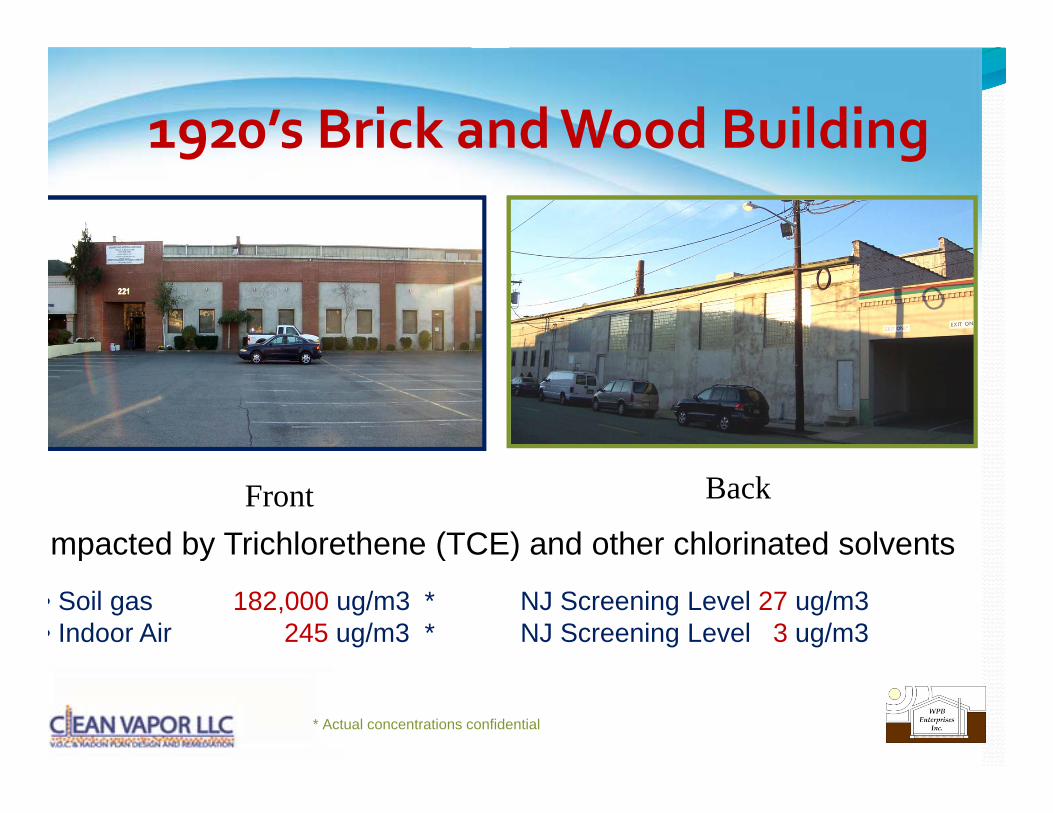
1920’s Brick and Wood Building9 g
Front Back
mpacted by Trichlorethene (TCE) and other chlorinated solventsp y ( )
• Soil gas 182,000 ug/m3 * NJ Screening Level 27 ug/m3 • Indoor Air 245 ug/m3 * NJ Screening Level 3 ug/m3
* Actual concentrations confidential
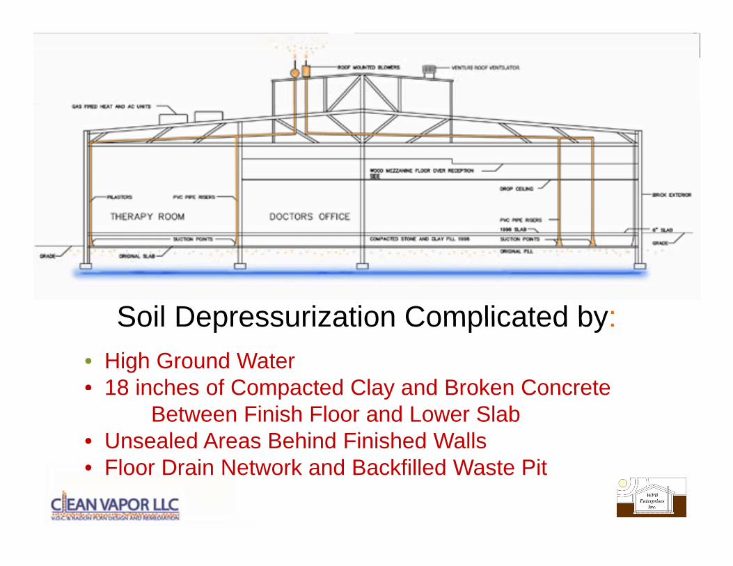
Soil Depressurization Complicated by:• High Ground Water• 18 inches of Compacted Clay and Broken Concrete
Soil Depressurization Complicated by:
18 inches of Compacted Clay and Broken Concrete Between Finish Floor and Lower Slab
• Unsealed Areas Behind Finished WallsFl D i N t k d B kfill d W t Pit• Floor Drain Network and Backfilled Waste Pit
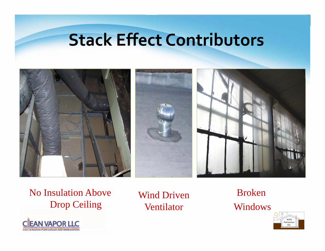
Stack Effect Contributors
No Insulation Above Drop Ceiling
BrokenWi d
Wind Driven V til tDrop Ceiling WindowsVentilator
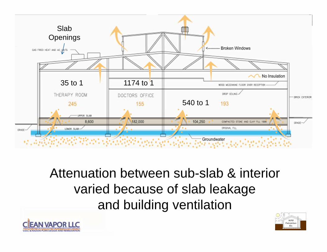
Slab Openings
540 to 1
1174 to 135 to 1
Attenuation between sub-slab & interiorAttenuation between sub-slab & interior varied because of slab leakage
and building ventilationand building ventilation
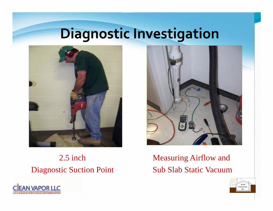
Diagnostic Investigation g g
2.5 inchDiagnostic Suction Point
Measuring Airflow andSub Slab Static VacuumDiagnostic Suction Point Sub Slab Static Vacuum
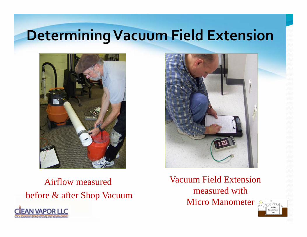
Determining Vacuum Field Extension g
Airflow measuredb f & ft Sh V
Vacuum Field Extension measured withbefore & after Shop Vacuum measured with
Micro Manometer
50 0
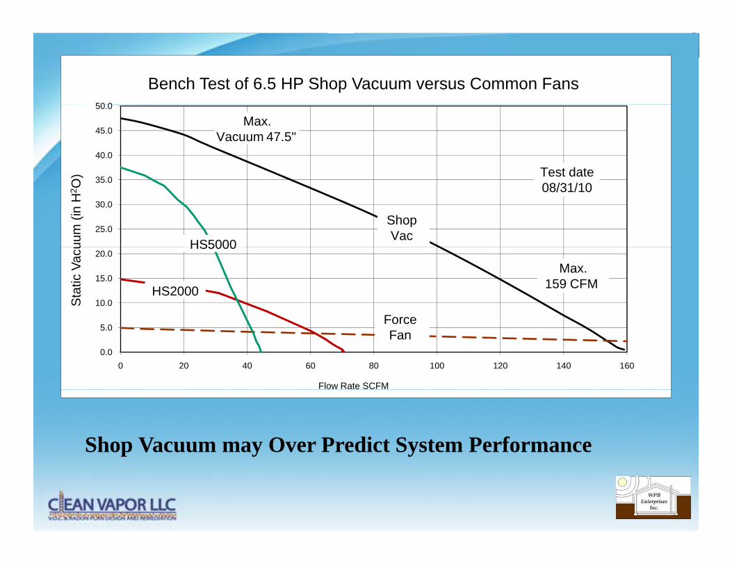
Bench Test of 6.5 HP Shop Vacuum versus Common Fans
40.0
45.0
50.0
)
Max.Vacuum 47.5"
Test date
25.0
30.0
35.0
uum
(in
H2 O
) Test date08/31/10
ShopVac
HS5000
10.0
15.0
20.0
Sta
tic V
acu
Max.159 CFM
HS5000
HS2000
Force
0.0
5.0
0 20 40 60 80 100 120 140 160
Flow Rate SCFM
Force Fan
Shop Vacuum may Over Predict System Performance

-0.008”0.008 PFE
radius from each
tisuctionhole
100' 0"
Total AirflowAirflow
528 CFM
Up
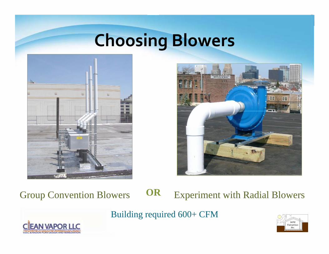
Choosing Blowersg
Group Convention Blowers OR Experiment with Radial Blowers
Building required 600+ CFM
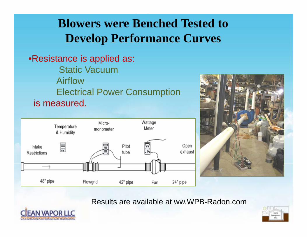
Blowers were Benched Tested to Develop Performance Curvesp
•Resistance is applied as:Static VacuumAirflowElectrical Power Consumption
is measuredis measured.
Results are available at ww.WPB-Radon.com
400020 0
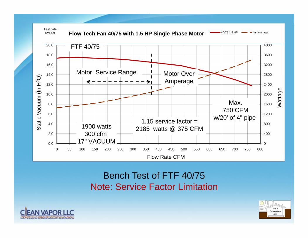
Flow Tech Fan 40/75 with 1.5 HP Single Phase Motor 40/75 1.5 HP fan wattageTest date12/1/09
2800
3200
3600
4000
14 0
16.0
18.0
20.0 FTF 40/75
Motor OverMotor Service Range
1600
2000
2400
2800
8 0
10.0
12.0
14.0
Wat
tage
uum
(In.
H2 O
)
Max
Motor Over Amperage
Motor Service Range
400
800
1200
1600
2 0
4.0
6.0
8.0 W
Sta
tic V
acu Max.
750 CFMw/20' of 4" pipe
1900 watts300 cfm
1.15 service factor = 2185 watts @ 375 CFM
0
400
0.0
2.0
0 50 100 150 200 250 300 350 400 450 500 550 600 650 700 750 800
Flow Rate CFM
300 cfm17" VACUUM
Bench Test of FTF 40/75Note: Service Factor Limitation

CFM01/13/2010
S7 Soil resistance versus Fan Airflow
1000CFM
600
Maximum airflow FT 40/75 350 cfm
100Force 120 ÷ 4 = 30 cfm
200
3007 suctions 4 suctions
FT 40/75
FT 40/75 350 ÷ 7 = 57 cfm
100
40
Force 120 ÷ 4 = 30 cfm
2 suctionsHS2000 68 ÷ 2 = 34 cfm
102" " 6 " 8 ""
2 suctions
"6""
HS2000Force
HS5000131 cfm during
PFE test1 10 100
Pressure drop in inches of water versus airflow
2 40 60" 80"8" 20"6"4"
S7 Therapy Rm = High Flow Suction Hole
01/13/2010
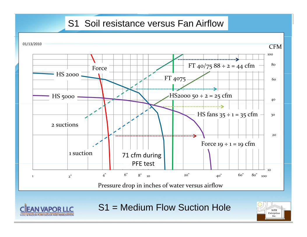
S1 Soil resistance versus Fan Airflow
100
CFM
HS 2000
80FT 40/75 88 ÷ 2 = 44 cfm
01/13/2010
ForceHS 2000 FT 4075
40
60
HS2000 50 ÷ 2 = 25 cfmHS 5000
2 suctions
30HS fans 35 ÷ 1 = 35 cfm
20
1 suctionForce 19 ÷ 1 = 19 cfm
71 cfm duringPFE test
101 10 100
Pressure drop in inches of water versus airflow2" 40" 60" 80"8" 20"4" 6"
PFE test
S1 = Medium Flow Suction Hole
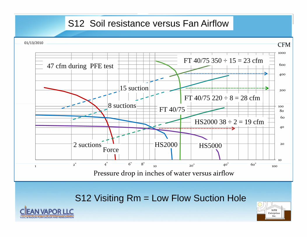
S12 Soil resistance versus Fan Airflow
CFM01/13/2010
1000
CFM
600
400
FT 40/75 350 ÷ 15 = 23 cfm
01/13/2010
47 cfm during PFE test
20015 suction
400
8 iFT 40/75 220 ÷ 8 = 28 cfm
100
40
60
80FT 40/758 suctions
HS2000 38 ÷ 2 = 19 cfm
10
20
6"
HS2000Force
" 6 "8"
2 suctions
4""
HS5000
1 10 100
Pressure drop in inches of water versus airflow6 20" 40" 60"8"42"
S12 Visiting Rm = Low Flow Suction Hole
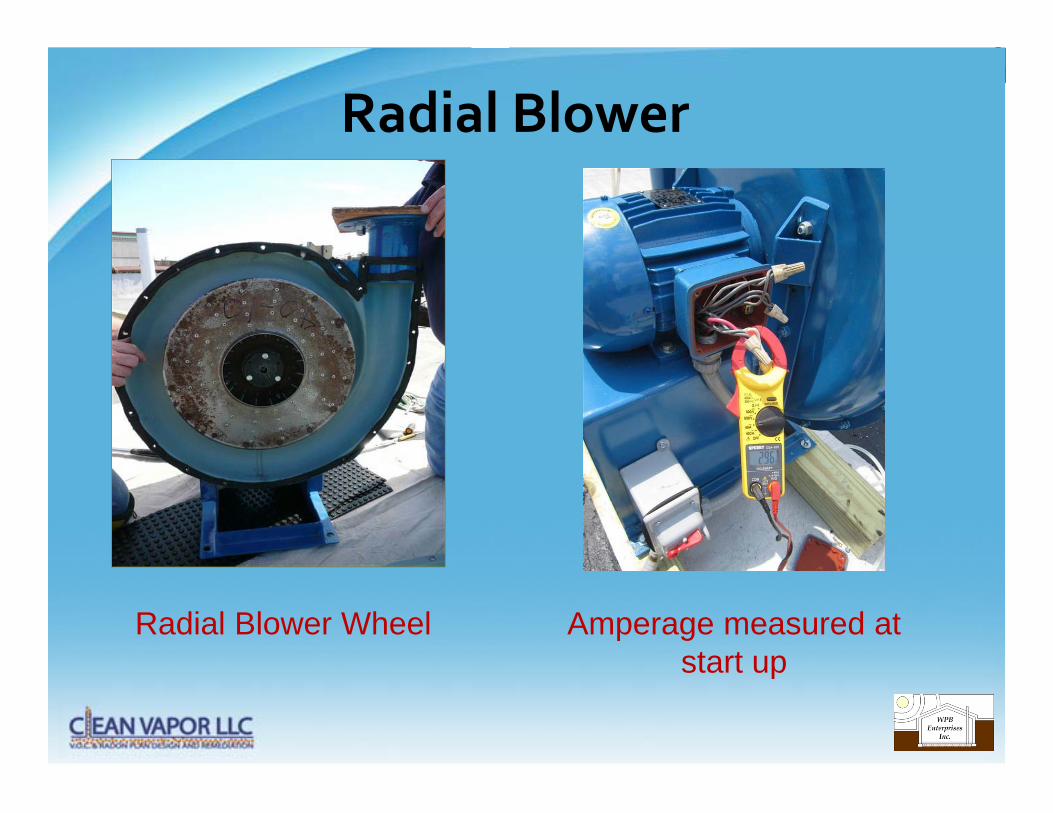
Radial Blower
Radial Blower Wheel Amperage measured at start upstart up
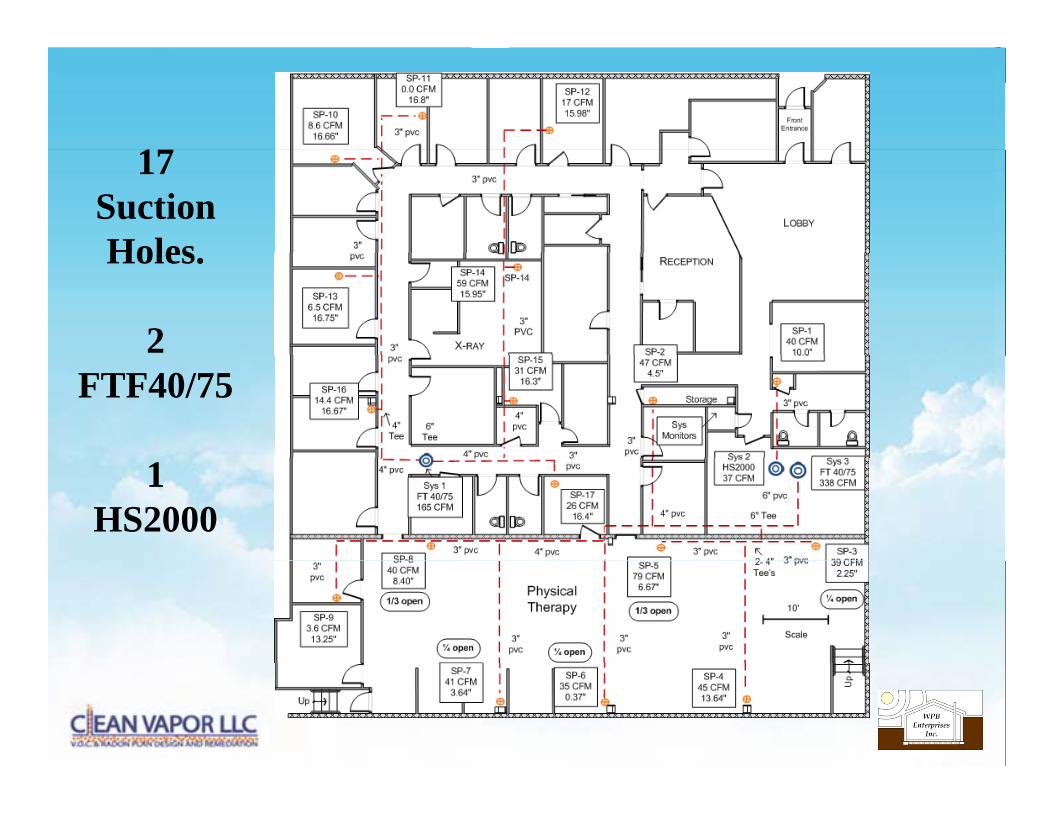
1717SuctionHolesHoles.
2 FTF40/75
1HS2000
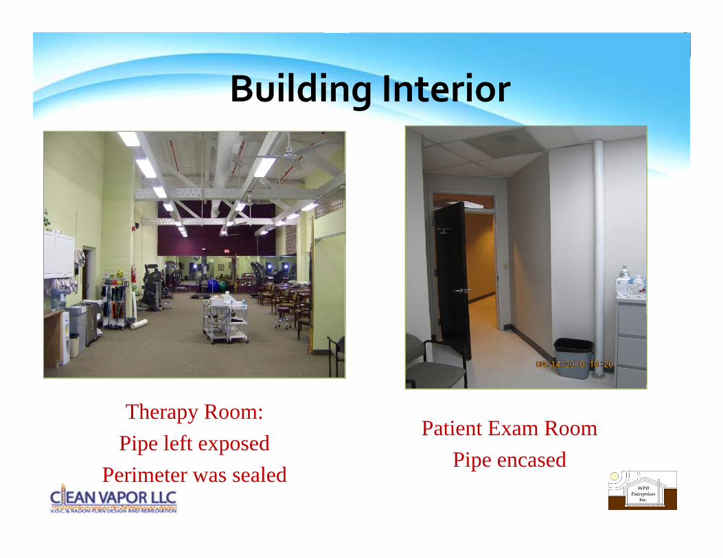
Building Interiorg
Patient Exam RoomPi d
Therapy Room:Pipe left exposed
Pipe encasedPerimeter was sealed
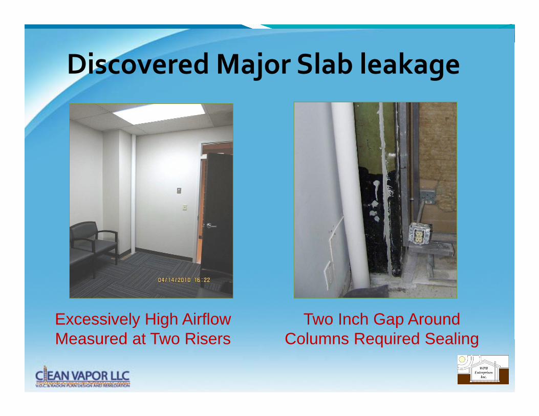
Discovered Major Slab leakagej g
Excessively High Airflow Measured at Two Risers
Two Inch Gap Around Columns Required SealingMeasured at Two Risers Columns Required Sealing
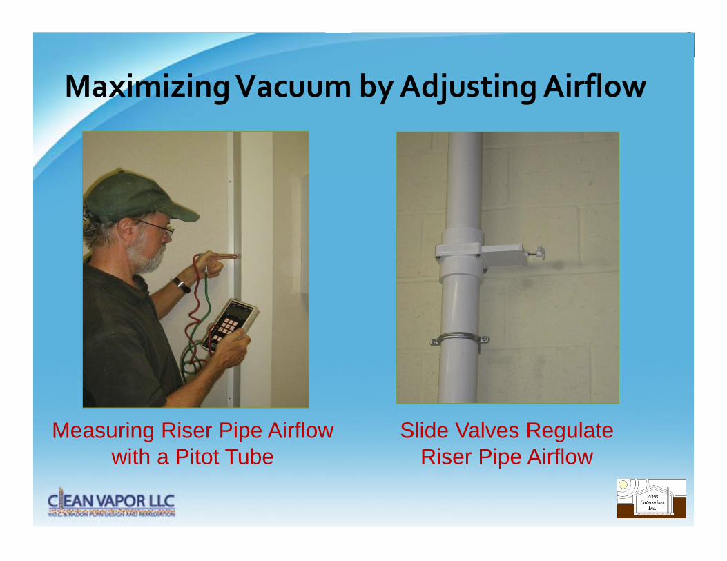
Maximizing Vacuum by Adjusting Airflowg y j g
Measuring Riser Pipe Airflow with a Pitot Tube
Slide Valves Regulate Riser Pipe Airflowwith a Pitot Tube Riser Pipe Airflow
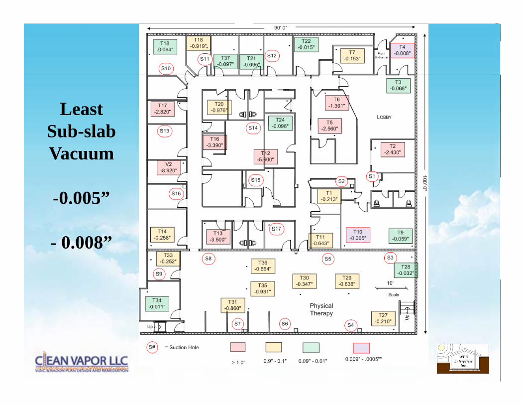
LeastS b l bSub-slabVacuum
-0.005”
- 0.008”
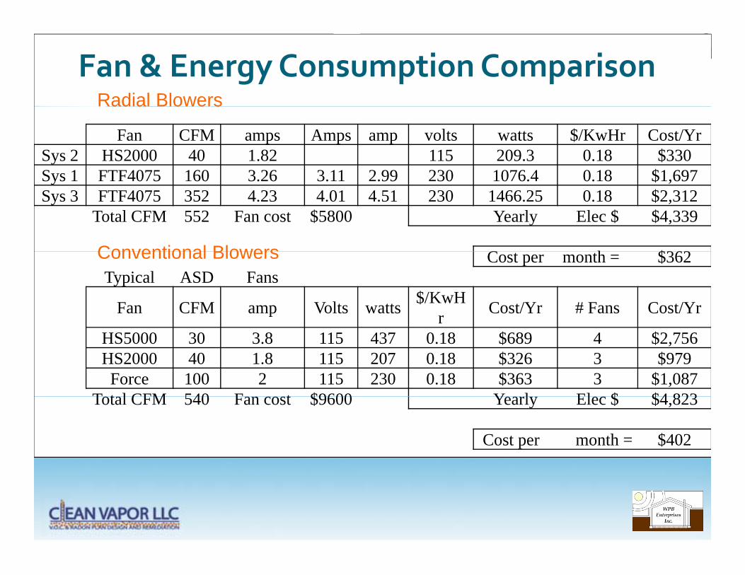
Fan & Energy Consumption ComparisonRadial Blowers
Fan CFM amps Amps amp volts watts $/KwHr Cost/YrSys 2 HS2000 40 1.82 115 209.3 0.18 $330Sys 1 FTF4075 160 3 26 3 11 2 99 230 1076 4 0 18 $1 697
Radial Blowers
Sys 1 FTF4075 160 3.26 3.11 2.99 230 1076.4 0.18 $1,697Sys 3 FTF4075 352 4.23 4.01 4.51 230 1466.25 0.18 $2,312
Total CFM 552 Fan cost $5800 Yearly Elec $ $4,339
C h $362Conventional Blowers Cost per month = $362Typical ASD Fans
Fan CFM amp Volts watts $/KwHr Cost/Yr # Fans Cost/Yr
Conventional Blowers
HS5000 30 3.8 115 437 0.18 $689 4 $2,756HS2000 40 1.8 115 207 0.18 $326 3 $979
Force 100 2 115 230 0.18 $363 3 $1,087T t l CFM 540 F t $9600 Y l El $ $4 823Total CFM 540 Fan cost $9600 Yearly Elec $ $4,823
Cost per month = $402
• Building Evaluation and Vacuum Field Extension Testing is Critical to Optimizing a Vapor Mitigation System p g p g y
• Using Fewer Blowers Reduces Energy and Installation cost
• Soil Resistance vs Blower Performance graphs help determine g p pOptimum Blower & Maximum # of Suctions
• System Optimized by Retesting Soil Resistance after Pit Excavation
• Sealing is Critical to System Performance
• Must NOT exceed Motor Service Factor
• Radial Blowers are an Effective Alternative to Multiple Regenerative Blowers for Low Permeability Soils