Embed Size (px)
Citation preview
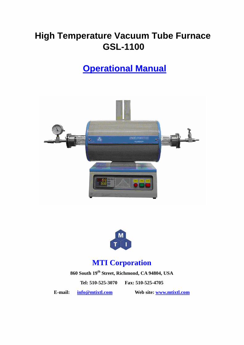
High Temperature Vacuum Tube Furnace GSL-1100
Operational Manual
MTI Corporation 860 South 19th Street, Richmond, CA 94804, USA
Tel: 510-525-3070 Fax: 510-525-4705
E-mail: [email protected] Web site: www.mtixtl.com
Content
Introduction .................................................................................................... 3 Technical Specifications................................................................................. 4
Furnace Structure ...................................................................................... 4 Operating environment ............................................................................. 4 Instrument features.................................................................................... 4
Operation ........................................................................................................ 5 Tube and flange installations .................................................................... 5 General Operation .....................................................................................5 Temperature Controller Instruction........................................................... 6 Temperature Controller Setting................................................................. 7 Temperature Segment Setting ................................................................... 7 Illustration of Temperature Segment Setting ............................................ 8 Run the program...................................................................................... 10
Temperature Controller Parameters ............................................................. 10 Introduction ............................................................................................. 10 Parameter Function ................................................................................. 10 Parameter Setting .................................................................................... 10
Troubleshooting for typical Problems............................................................ 6
Thank you for purchasing MTI’s products, please read this manual before using the furnace, MTI has no responsibility for any damage caused by customer’s misuse.
Notice: The specification data may be different from the data on our website because we keep upgrading the products,
if any confusion, please visit MTI’s website at www.mtixtl.com for the latest data.

Introduction
GSL-1100 series high temperature vacuum tube furnace is a compact designed for heating samples up to 1100 0C. Stainless steel vacuum flange with valve, vacuum gauge and quartz tube are included for immediate use. Built in precision temperature controller is able to program the heating rate, dwell time and cooling rate up to 30 segments. The furnace can be set up in both vertical and horizontal position to meet various applications such as firing sample, VSL and CVD. It is an excellent furnace for annealing, diffusing and sintering sample in various atmospheres.
Operating Voltage: 110V AC±10
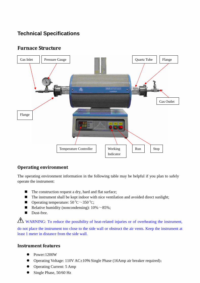
Technical Specifications
Furnace Structure
Operating environment
The operating environment information in the following table may be helpful if you plan to safely operate the instrument:
� The construction request a dry, hard and flat surface; � The instrument shall be kept indoor with nice ventilation and avoided direct sunlight; � Operating temperature: 50 0C~350 0C; � Relative humidity (noncondensing): 10%~85%; � Dust-free.
WARNING: To reduce the possibility of heat-related injuries or of overheating the instrument,
do not place the instrument too close to the side wall or obstruct the air vents. Keep the instrument at least 1 meter in distance from the side wall.
Instrument features
� Power:1200W
� % Single Phase (16Amp air breaker required);
� Operating Current: 5 Amp
� Single Phase, 50/60 Hz
Pressure Gauge Quartz Tube Flange
Gas Outlet
Temperature Controller
Flange
Gas Inlet
Run Working
Indicator
Stop

� Overall Dimensions D x H x W (inch): 10" x 15" x 16" (26 x38 x40 cm);
� 304 stainless steel chamber;
� Operating Temp Range C: 200 0C ~1100 0C
� Temperature accuracy: +/- 1 0C;
� Suggested Normal Heating Rate: ≤10 0C /min
� Max. Heating Rate: ≤ 30 0C /min;
� Constant Temperature zone: 3.1" ( 80 mm);
� Temperature control: 30 segments programmable digital controller with PID function and overheated and overloaded protection;
� Vacuum Level: 1.0×10⁻³ Pa;
; �
Heating Elements: Fe-Cr-Al Alloy doped by Mo;
�
Shipping Dimension: 21"x23"x25"(530 x 590 x 640mm);
�
Net weight (lb): 40 lbs;
�
Warranty: One Year limited, not included quartz tub
e.
Operation
Tube and flange installations
Once you received MTI furnace, please follow these steps to set up the furnace.
� Open the box; check out if the instrument and the accessories are well kept during the shipping.
� The instrument shall be kept indoor with nice ventilation;
� Slightly insert the quartz tube from one side;
� Insert the foam block and seal the tube at both ends with flanges.
General Operation
� Place the test sample inside the tube, slightly insert the foam block and then seal both end of the tube with flanges.
� If you are going to set up the Vacuum/Gas Flow system with the furnace, please properly set the vacuum level / flowing rate when you need to purge and charge the inert gas into the tube. It is highly recommended to apply vacuum grease on the flange joint, please visit: http://www.mtixtl.com/furnaceaccessories.aspx for more information.

� Properly connect to the power supply and make sure it is well grounded;
� Power on the instrument by pressing “Run” button and you will see the control panel start to blink.
� Please refer to the following part “Temperature Controller Instruction” for how to set the temperature curve.
NOTE::::Once you finish the set up, we strongly recommend our customer FIRSTLY reading the handbook and then following the instructions of attached “QUICK TEST” inside the package to perform a quick test to check the heating condition of the furnace.
CAUTION: To reduce the risk of electric shock or damage to your instrument during your
quick test, observe these practices:
� The outer plate of the instrument must be grounded properly, for safety of operation; � The instrument shall be kept indoor with nice ventilation; � To reduce potential safety issues, do not place flammable and explosive materials around the
instrument; � No explosion-proof, do not put any flammable and explosive materials into the chamber.
Temperature Controller Instruction
MTI provide two kinds of temperature controller wit h same function:
Here, we will introduce the left one:
Furnace Temp. (PV)
Setting Temp. (SV)
Increase button (END)
Decrease button (RUN/PE)
Program setting/Left Shift/Auto-tune (AT/PROTA/M)
Parameter setting/Start the Program, view the time running (SET PAR)
Function Indicating

Temperature Controller Setting
Startup state When start the device, the meter type and program version will display for a few seconds, and then enter the normal state. Blinking “End” indicates the program is in stop state.
Meter type & Program version Normal state
Displaying switch
a. In the “normal state” or “program running state”, press “SET” key for 1 second
to switch to “executing program segment” (Set executing segment or display
the ongoing temperature segment).
b. Press “SET” key again for 1 second to switch to “running time state” (Display the
total running time PV xxxx min. and the elapsed time SV xxxx min.) c. Press “SET” key again for 1 second to back to “normal state”.
Temperature Segment Setting
LTDE programmable smart instrumentation auto-controller allows you to set the temperature profile up to 30 segments. To process this function, follow these steps:
� Power on the furnace, blinking “End” on the SV window indicates the Normal State;
� Press “←” once to display “C01” on PV window;
� Set initial temperature to 0 oC by using Keystrokes :“←”, “ ↑” or “↓”;
� Press “Set” to display “t01” on PV window;
� Set heat-up time (Usually beyond 30 minutes for this segment in case of temperature
overshooting) from initial temperature to target temperature by using Keystrokes :“←”, “ ↑” or
“↓”;

� Press “Set” to display “C02” on PV window; Set the actual working temperature for the second
segment by using Keystrokes :“←”, “ ↑” or “↓”;
� Press “Set” to display “t02” on PV window; Set heat-up time from initial temperature to target
temperature by using Keystrokes :“←”, “ ↑” or “↓”;
� Press “Set” to display “C03” on PV window, Set the actual working temperature for the third segment;
� Press “Set” to display “t03” on PV window; Set heat-up time from initial temperature to target temperature;
� Press “Set” to display “C04” on PV window, Set the actual working temperature for the fourth segment;
� Press “Set” to display “t04” on PV window, Use Keystrokes :“←”, “ ↑” or “↓” to set duration for “C04”;
� By pressing “Set”, you can get into the following segments (C05&t05…C06&t06…C07&t07…) for temperature and time setting;
� Press “Set” to display “Cxx” on PV window (xx could be any values among 01~30); � Press“←”, “ ↑” or “↓” to set “-121” in the last segment in order to shut down the furnace;

Illustration of Temperature Segment Setting
Setting Example:
According to figure I above, all segments was recorded in the following: Prompt Input Data Description
C01 0 Initial Temperature
T01 45 Heat-up time 45 minutes from 0-450 oC in the first segment
C02 450 Target temperature of the first heat-up stage
T02 20 Heat-up time 20 minutes from 450-500 oC in the second segment
C03 500 Target temperature of the second heat-up stage
T03 40 Keep 40 minutes at 500 oC
C04 500 Constant temperature of the third stage
T04 30 Heat-up time 30 minutes from 500-1000oC in the fourth segment
C05 1000 Target temperature of the fourth heat-up stage
T05 25 Keep 25 minutes at 1000oC
C06 1000 Constant temperature of the fourth stage
T06 20 Cooling time 20 minutes from 1000 to 800oC
C07 800 Target temperature of the fifth heat-up stage
T07 25 Keep 25 minutes at 800oC
C08 800 Constant temperature of the sixth stage
T08 -121 Program end, Out-put power off. Furnace cooling down naturally.
(t08 = -121 is an order to stop running)
Run the program
� When temperature program set up ready, wait until “End” shows on SV window again, then press “↓”and hold for two seconds to display “Run” on SV window;
� Furnace will run automatically segment by segment according to the program setting; � PV window displays increasing temperature at this moment;
Hold the program
� If you need to hold the furnace at certain temperature when the program is running, press “↓” for 2 sec to hold the program and again press it to continue.
Stop the program
� You can stop the program either from running or hold state by pressing “↑” for 2 seconds.
Attention:
� When finish all the segments you need, please end the last segment with -121; � It is not suggested to modify any parameters during the execution if he or she is not familiar
with the furnace operation. If there is a must, please first stop the program.
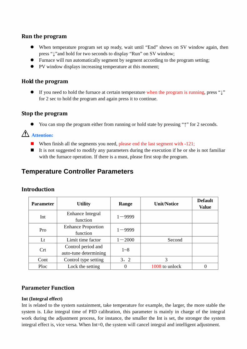
Temperature Controller Parameters
Introduction
Parameter Utility Range Unit/Notice Default Value
Int Enhance Integral
function 1-9999
Pro Enhance Proportion
function 1-9999
Lt Limit time factor 1-2000 Second
Crt Control period and
auto-tune determining 1~8
Cont Control type setting 3,2 3 Ploc Lock the setting 0 1008 to unlock 0
Parameter Function
Int (Integral effect) Int is related to the system sustainment, take temperature for example, the larger, the more stable the system is. Like integral time of PID calibration, this parameter is mainly in charge of the integral work during the adjustment process, for instance, the smaller the Int is set, the stronger the system integral effect is, vice versa. When Int=0, the system will cancel integral and intelligent adjustment.

Pro (Proportion effect) Pro is used for adjusting proportion and differential effect. The larger Pro is, the smaller proportion effect is, which means both adjustment and differential effect are enhanced to get sensitive ability to the temperature change, vise versa.
Lt (Delay time coefficient) Lt is used to determine tradeoff of the proportion and differential. When it is small, proportion is strong and differential is weak, vise versa. If Lt is no more than the twice of Crt (will mention below), differential effect is off. Note: The three parameters discussed above should be adjusted after “auto-tune”.
Crt (Period control and auto-tune determination) Crt is applied for adjusting the calculation cycle (unit is second), which makes critical impact on the system adjustment and of course, if it is set properly, we can better solve the temperature overshooting and system oscillating. Please remember to set this value before auto-tune since Crt may give a direct effect on it. Generally, set Crt in the range of 1~8 if main circuit adopts solid relay or controllable silicon unit; more than 8 if main circuit uses alternative current contactor; if Cont=0, set it as 0. Also, this parameter determines result of auto-tune: if it is revised after auto-auto, the auto-tune fails, please revise the value manually and restart auto-tune.
Cont (Controlling type) When Cont=2, system starts auto-tune function to work out the value for Int, Pro and Lt, and then system will go to 3.When CtrL=3, adopts advanced AI adjustment, after auto-tune, the system goes to this setting mode, note that you can not startup auto-tune function from the controller panel, for a

protection of repeating auto-tune, when you need a re-auto-tune, please set it as 2.
Actually , “auto-tone” function could produce exact parameters for a general use. However, nobody could decide an absolutely stable electronic specification of each heating material (like resistance may vary because of temperature or time going by) or the difference between the temperature heating segments. Hence, the “auto-tune” may be not ideal. If so, you can manually modify Int, Pro and Lt
PLOC:::: Function lock, no need to revise if general use.
Parameter Setting
� In the “normal state”, press “SET” key for 2 seconds, you will see parameter “Int” pops up and press “←”, “ ↑” or “↓” to modify the parameter.
� Press “SET” key for 1 second to go to next parameter and press “←”+“ ↓” for 1 seconds to back to preceding parameter.
� Press “←” and then press “SET” key to back up to “normal state”. Without any operation on the keys for about 30 minutes, the meter will automatically exit from “parameter setting state”.

Troubleshooting for typical Problems
Troubleshooting resources
� Refer to “Quick troubleshooting”, the next section in this chapter; � Visit MTI web site link: WWW.MTIXTL.COM for additional information about the
instrument through Help and Support; � Contact us by tel: 510-525-3070 or email: [email protected].
Maintenance and Caution
1. In order to prevent the furnace module from splitting, the furnace shall be used after being heated for 1 hour at 120 oC and 2 hours at 300 oC if you firstly apply it or have left it aside for long. Never keep the furnace temperature over rated temperature for avoiding damage on heating element or cover. Do not pour any liquid or melting metal into the module to keep clean inside.
2. When applying the furnace with quartz tube and the temperature over 1000 oC, the high temperature part of the tube will be opaque (devitrification), it is a normal phenomenon because of quartz property.
3. Set a medium heating rate and small temperature difference between adjacent segment when the furnace is cool. Please make a considerate setting on the heating rate in terms of the character of material sintered.
4. Termly check the wire connection and link junction of the heating element.
5. Change the silicon rubber ring inside the flange and reassemble the flange, or the vacuum system if the vacuum value declines obviously.
6. Please refer to parameter “M5, P and t” setting if the temperature offset can not be eliminated and the difference between PV and SV goes far at 300 oC.
7. Working environment
a. Circumstance temperature: -10~75 oC.
b. Relative humidity: 85%
c. Keep from electric dust, explosive and corrosive gas.
d. Keep stable position when working. 8. MTI’ furnace (not including tube and heating element) has one year warranty since it is shipped
out. We will give you free maintenance if there is a quality problem. For any misuse and damage, we will make a charge according to the damage condition if there is a requirement of mending. Notice: MTI never suggest you put any noxious, explosive or flammable gas into the tube. Please remember that the inside air pressure ≤ 0.05 Mpa and over pressure use is forbidden when applying quartz tube or corundum tube at high temperature. We have no responsibility for your safety if you are out of this notice.
Quick Troubleshooting
The furnace is unable to start up
If the furnace can not turn on when you press the power button: � Be sure the furnace is plugged into and AC outlet with adequate power; � Fuse in controlling circuit might failure. Check the control circuit and replace the fuse.
The temperature inside the chamber can’t go up
� Temperature may be set too low, adjust the setting value of temperature;
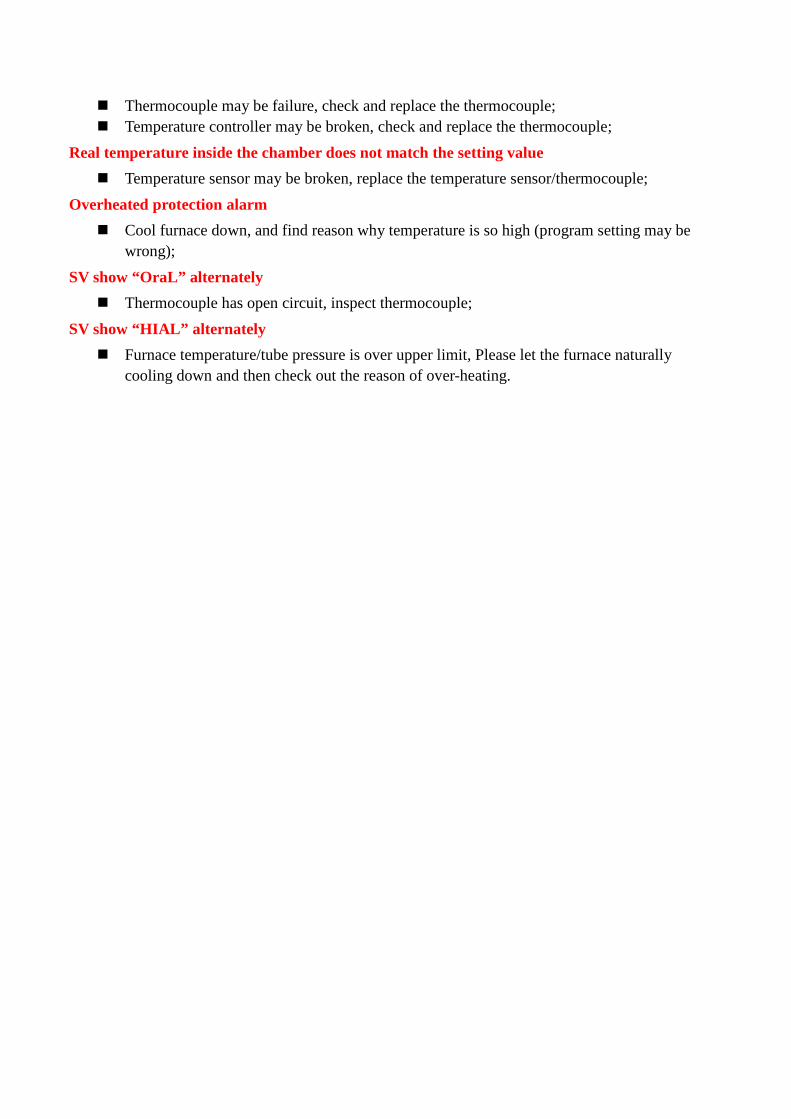
� Thermocouple may be failure, check and replace the thermocouple; � Temperature controller may be broken, check and replace the thermocouple;
Real temperature inside the chamber does not match the setting value
� Temperature sensor may be broken, replace the temperature sensor/thermocouple;
Overheated protection alarm
� Cool furnace down, and find reason why temperature is so high (program setting may be wrong);
SV show “OraL” alternately
� Thermocouple has open circuit, inspect thermocouple;
SV show “HIAL” alternately
� Furnace temperature/tube pressure is over upper limit, Please let the furnace naturally cooling down and then check out the reason of over-heating.