Embed Size (px)
Citation preview
Vol. 7, No. 1, 2004 High Temperature Degradation in Power Plants and Refineries 103Materials Research, Vol. 7, No. 1,1 103-110, 2004. © 2004
*e-mail: [email protected], [email protected] at the International Symposium on High Temperature Corrosionin Energy Related Systems, Angra dos Reis - RJ, September 2002.
High Temperature Degradation in Power Plants and Refineries
Heloisa Cunha Furtadoa*, Iain Le Mayb*
aCEPEL, Centro de Pesquisas de Energia ElétricaC.P. 2754, Cidade Universitaria, 20001-970 Rio de Janeiro - RJ, Brazil
bMetallurgical Consulting Services Ltd.P.O. Box 5006, Saskatoon, SK S7K 4E3, Canada
Received: September 2, 2002; Revised: September 4, 2002
Thermal power plants and refineries around the world share many of the same problems,namely aging equipment, high costs of replacement, and the need to produce more efficientlywhile being increasingly concerned with issues of safety and reliability. For equipment operatingat high temperature, there are many different mechanisms of degradation, some of which interact,and the rate of accumulation of damage is not simple to predict. The paper discusses the mecha-nisms of degradation at high temperature and methods of assessment of such damage and of theremaining safe life for operation.
Keywords: degradation mechanisms, high temperature, life assessment, power plants, refineries
1. Introduction
Thermal power plants and refineries around the worldare aging and need to be assessed to ensure continued safeoperation. Replacement is frequently not an option becauseof high capital costs, and the much lower cost of continuingthe operation of the older plant. However, reliability andsafety are issues that have become much more important inrecent years, so the assessment of damage and of the riskassociated with failure have become increasingly important.In order to make such assessments on a sound basis, it isnecessary to know the potential mechanisms of degrada-tion and the rate of accumulation of damage that may beexpected with each.
2. Deterioration mechanisms
The principal deterioration mechanisms in high tempera-ture plant are creep damage, microstructural degradation,high temperature fatigue, creep-fatigue, embrittlement, car-burization, hydrogen damage, graphitization, thermal shock,erosion, liquid metal embrittlement, and high temperaturecorrosion of various types. Additionally, stress corrosioncracking and aqueous corrosion may be problems althoughthese damage mechanisms are not generally expected in hightemperature components: however they may occur when
components are cooled down and liquid is still present withinor in contact with them. Aspects of each will be consideredin turn.
2.1. Creep
Creep is one of the most serious high temperature dam-age mechanisms. It involves time-dependent deformationand high temperature creep cracking generally develops inan intercrystalline manner in components of engineeringimportance that fail over an extended time. These includeboiler superheater and other components operating at hightemperature, petrochemical furnace and reactor vessel com-ponents and gas turbine blades. At higher temperatures, ascan occur with local overheating, deformation may be lo-calized, with large plastic strains and local wall thinning.At somewhat lower temperatures and under correspondinglyhigher stress levels, fracture can be transgranular in nature.To characterize the type of deformation and the relevantfracture mechanisms to be expected or to correlate observeddeformation and fracture characteristics with probable op-erating conditions, deformation and fracture mechanismmaps as developed by Ashby1 and Mohamed and Langdon2
can be useful in this regard.
104 Furtado & Le May Materials Research
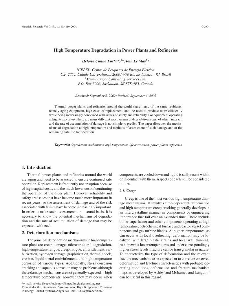
Classification of creep damage in steam generators hasbeen made using the largely qualitative approach ofNeubauer and Wedel3 based on the distribution of creep voidsand microcracks observed by in situ metallography, and il-lustrated schematically in Fig. 1. However, as has beenshown subsequently, the method is unreliable for CrMosteels, at least, as apparent voids may be developed duringthe polishing and etching sequence4-5. Replica metallographyis useful, however, and the degree of spheroidization of car-bides in bainitic and pearlitic structures can provide a goodindication of the degree of thermal exposure and can becorrelated with the extent of creep damage6. Used in con-junction with hardness measurements, indicating loss oftensile strength, these semi-quantitative tools have servedto allow estimates of remaining safe life to be made of com-ponents undergoing damage by creep.
2.2. Microstructural degradation
Microstructural degradation is a damage mechanism thatcan lead to failure by some other process such as creep,fatigue or more rapid fracture. It is important that it is rec-ognized as a mechanism of damage as it can result in a sig-nificant loss in strength in a material. It is appropriate todiscuss this following directly upon the discussion of creepdamage, because the two mechanisms are closely boundtogether and, indeed, are difficult to separate. It has alreadybeen noted that Cr-Mo steels that are liable to fail by creepin a short time may display spheroidization of the carbidesbut little, if any, void formation. The formation of voidsappears, in many cases, to be a very local phenomenon oc-curring very close to the time of fracture. It is worth com-menting that the approach of Kachanov7 to the accumula-tion of damage (the continuum damage approach), postu-lating a loss of effective area or a loss in resistance to defor-mation, does not require any actual voids or loss of cross-section, and microstructural damage may be the dominantaspect of reduction in creep strength. Thus, evaluation ofthe potential for creep failure and the extent of creep dam-age needs to take account of microstructural changes. Thismay be done directly or through a measurement of thechange in hardness, as this quantity provides an indicationof the resistance of a material to deformation. Recently,Dyson8 has discussed continuum damage mechanics mod-elling of creep in terms of several damage mechanisms, in-cluding microstructural degradation.
Another example of microstructural degradation isdecarburization of carbon or alloy steel when exposed to anoxidizing atmosphere at high temperature. There is a lossof strength in the surface layer of the steel.
2.3. High temperature fatigue and thermal fatigue
Fatigue, involving repeated stressing, can lead to failureat high temperature as it does at low temperature. In com-
ponents operating at high temperature it often arises throughtemperature changes that can lead to cyclic thermal stresses.This can lead to thermal fatigue cracking. The cracking tendsto develop in areas of high constraint, and the detailedmechanism may be one of local creep deformation.
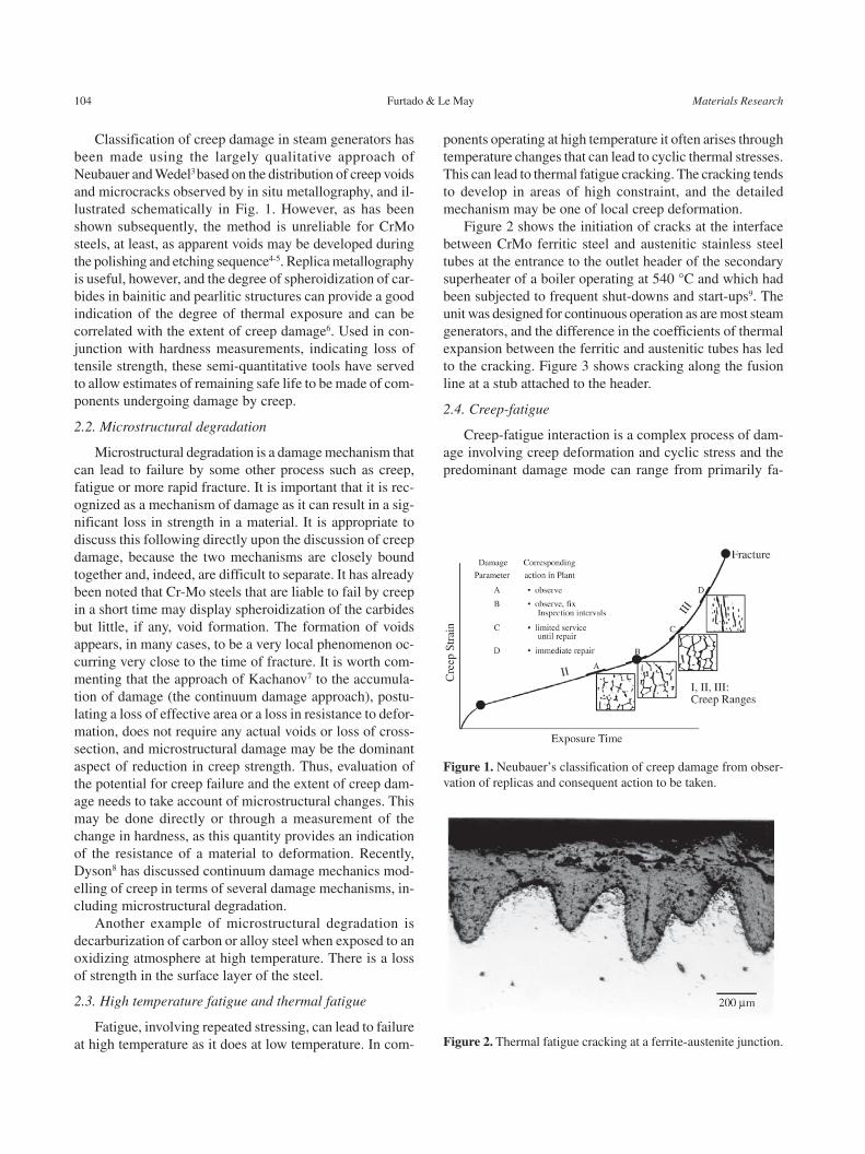
Figure 2 shows the initiation of cracks at the interfacebetween CrMo ferritic steel and austenitic stainless steeltubes at the entrance to the outlet header of the secondarysuperheater of a boiler operating at 540 °C and which hadbeen subjected to frequent shut-downs and start-ups9. Theunit was designed for continuous operation as are most steamgenerators, and the difference in the coefficients of thermalexpansion between the ferritic and austenitic tubes has ledto the cracking. Figure 3 shows cracking along the fusionline at a stub attached to the header.
2.4. Creep-fatigue
Creep-fatigue interaction is a complex process of dam-age involving creep deformation and cyclic stress and thepredominant damage mode can range from primarily fa-
Figure 1. Neubauer’s classification of creep damage from obser-vation of replicas and consequent action to be taken.
Figure 2. Thermal fatigue cracking at a ferrite-austenite junction.
Vol. 7, No. 1, 2004 High Temperature Degradation in Power Plants and Refineries 105
tigue crack growth at higher frequencies and lower tem-peratures to primarily creep damage where hold times arelong and temperature is at the high end of the scale.
2.5. Embrittlement and carburization
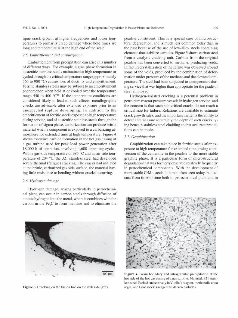
Embrittlement from precipitation can arise in a numberof different ways. For example, sigma phase formation inaustenitic stainless steels maintained at high temperature orcycled through the critical temperature range (approximately565 to 980 °C) causes loss of ductility and embrittlement.Ferritic stainless steels may be subject to an embrittlementphenomenon when held at or cooled over the temperaturerange 550 to 400 °C10. If the temperature conditions areconsidered likely to lead to such effects, metallographicchecks are advisable after extended exposure prior to anunexpected rupture developing. In addition to theembrittlement of ferritic steels exposed to high temperatureduring service, and of austenitic stainless steels through theformation of sigma phase, carburization can produce brittlematerial when a component is exposed to a carburizing at-mosphere for extended time at high temperature. Figure 4shows extensive carbide formation in the hot gas casing ofa gas turbine used for peak load power generation after18,000 h of operation, involving 1,600 operating cycles.With a gas-side temperature of 985 °C and an air side tem-perature of 204 °C, the 321 stainless steel had developedsevere thermal (fatigue) cracking. The cracks had initiatedat the brittle, carburized gas side surface, the material hav-ing little resistance to bending without cracks occurring.
2.6. Hydrogen damage
Hydrogen damage, arising particularly in petrochemi-cal plant, can occur in carbon steels through diffusion ofatomic hydrogen into the metal, where it combines with thecarbon in the Fe
3C to form methane and to eliminate the
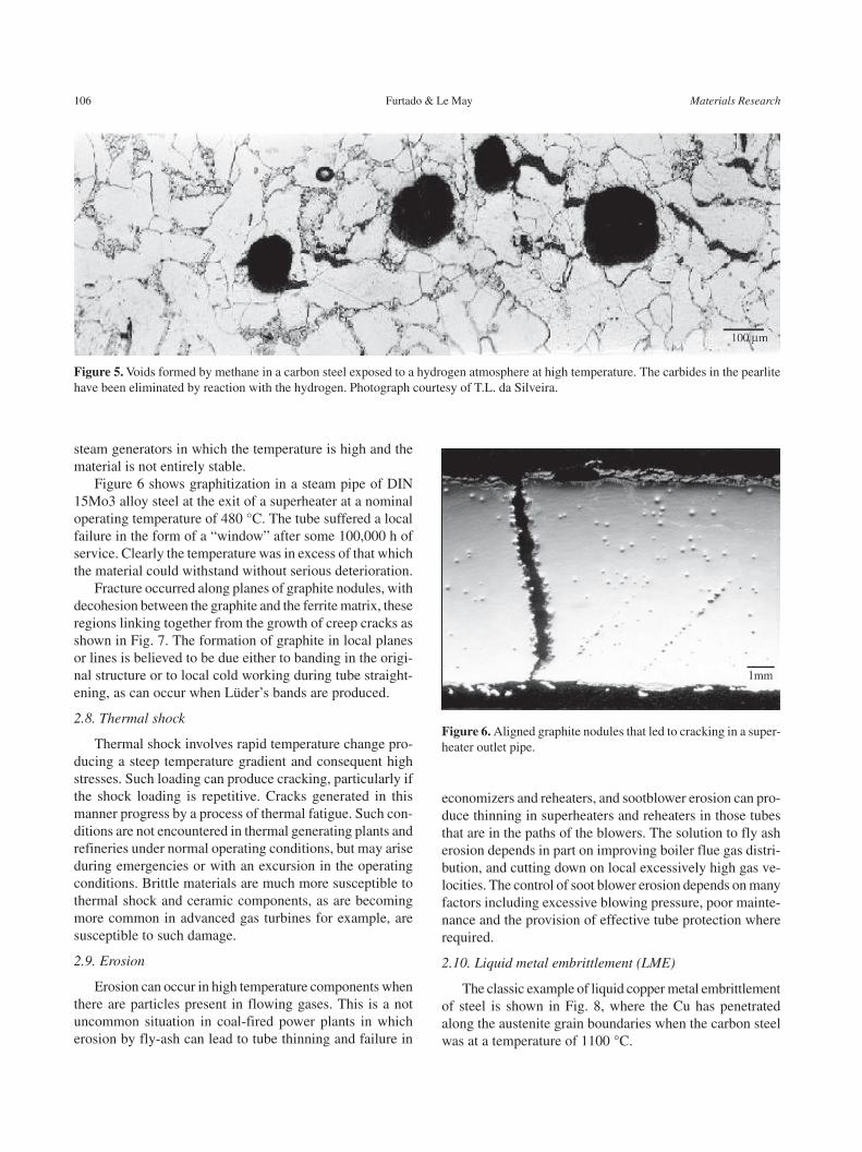
pearlite constituent. This is a special case of microstruc-tural degradation, and is much less common today than inthe past because of the use of low-alloy steels containingelements that stabilize carbides. Figure 5 shows carbon steelfrom a catalytic cracking unit. Carbide from the originalpearlite has been converted to methane, producing voids.In fact, recrystallization of the ferrite was observed aroundsome of the voids, produced by the combination of defor-mation under pressure of the methane and the elevated tem-perature. The steel had been subjected to a temperature dur-ing service that was higher than appropriate for the grade ofsteel employed.
Hydrogen-assisted cracking is a potential problem inpetroleum reactor pressure vessels in hydrogen service, andthe concern is that such sub-critical cracks do not reach acritical size for failure. Relations are available to estimatecrack growth rates, and the important matter is the ability todetect and measure accurately the depth of such cracks ly-ing beneath stainless steel cladding so that accurate predic-tions can be made.
2.7. Graphitization
Graphitization can take place in ferritic steels after ex-posure to high temperature for extended time, owing to re-version of the cementite in the pearlite to the more stablegraphite phase. It is a particular form of microstructuraldegradation that was formerly observed relatively frequentlyin petrochemical components. With the development ofmore stable CrMo steels, it is not often seen today, but oc-curs from time to time both in petrochemical plant and in
Figure 3. Cracking on the fusion line on the stub side (left).
Figure 4. Grain boundary and intragranular precipitation at thehot side of the hot gas casing of a gas turbine. Material: 321 stain-less steel. Etched successively in Vilella’s reagent, methanolic aquaregia, and Groesbeck’s reagent to darken carbides.
106 Furtado & Le May Materials Research
steam generators in which the temperature is high and thematerial is not entirely stable.
Figure 6 shows graphitization in a steam pipe of DIN15Mo3 alloy steel at the exit of a superheater at a nominaloperating temperature of 480 °C. The tube suffered a localfailure in the form of a “window” after some 100,000 h ofservice. Clearly the temperature was in excess of that whichthe material could withstand without serious deterioration.
Fracture occurred along planes of graphite nodules, withdecohesion between the graphite and the ferrite matrix, theseregions linking together from the growth of creep cracks asshown in Fig. 7. The formation of graphite in local planesor lines is believed to be due either to banding in the origi-nal structure or to local cold working during tube straight-ening, as can occur when Lüder’s bands are produced.
2.8. Thermal shock
Thermal shock involves rapid temperature change pro-ducing a steep temperature gradient and consequent highstresses. Such loading can produce cracking, particularly ifthe shock loading is repetitive. Cracks generated in thismanner progress by a process of thermal fatigue. Such con-ditions are not encountered in thermal generating plants andrefineries under normal operating conditions, but may ariseduring emergencies or with an excursion in the operatingconditions. Brittle materials are much more susceptible tothermal shock and ceramic components, as are becomingmore common in advanced gas turbines for example, aresusceptible to such damage.
2.9. Erosion
Erosion can occur in high temperature components whenthere are particles present in flowing gases. This is a notuncommon situation in coal-fired power plants in whicherosion by fly-ash can lead to tube thinning and failure in
economizers and reheaters, and sootblower erosion can pro-duce thinning in superheaters and reheaters in those tubesthat are in the paths of the blowers. The solution to fly asherosion depends in part on improving boiler flue gas distri-bution, and cutting down on local excessively high gas ve-locities. The control of soot blower erosion depends on manyfactors including excessive blowing pressure, poor mainte-nance and the provision of effective tube protection whererequired.
2.10. Liquid metal embrittlement (LME)
The classic example of liquid copper metal embrittlementof steel is shown in Fig. 8, where the Cu has penetratedalong the austenite grain boundaries when the carbon steelwas at a temperature of 1100 °C.
Figure 5. Voids formed by methane in a carbon steel exposed to a hydrogen atmosphere at high temperature. The carbides in the pearlitehave been eliminated by reaction with the hydrogen. Photograph courtesy of T.L. da Silveira.
Figure 6. Aligned graphite nodules that led to cracking in a super-heater outlet pipe.
Vol. 7, No. 1, 2004 High Temperature Degradation in Power Plants and Refineries 107
Liquid metal embrittlement can occur with a number ofliquid-solid metal combinations, and one that can have se-rious consequences for the refining industry is LME of auste-nitic stainless steel by zinc. Rapid embrittlement can occurat temperatures above 750 °C, and has been observed toproduce widespread cracking in stainless steel componentsafter a fire when there is a source of Zn present such asgalvanized steel structural parts, or when there is contami-nation from Zn-based paints11. This latter source led to con-siderable cracking at the time of the Flixborough disaster12.Cracking can be extremely rapid (m/s) and stress levels canbe as low as 20 MPa for such cracking to take place13.
Two types of attack are believed to occur in the processof Zn-embrittlement of austenitic stainless steel14, as illus-trated in Fig. 9. Type 1 embrittlement is a relatively slowprocess, controlled by the rate of diffusion along austenitegrain boundaries, and involves the combination of Zn withNi, this producing Ni-depleted zones along the boundaries.As a consequence, the FCC austenite structure transformsto BCC ferrite, producing expansion and a stress that initi-ates cracking. Type 2 embrittlement occurs at a much fasterrate, requiring an external stress to facilitate crack initia-tion. Cracking will not occur in the presence of a substan-tial oxide film unless this is ruptured locally.
Figure 10 shows an example of LME cracking by Zn inan austenitic steel as a result of a fire in a refinery and the
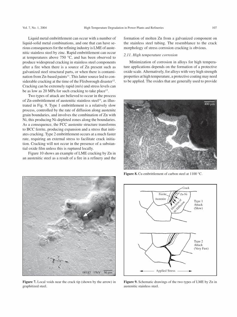
Figure 7. Local voids near the crack tip (shown by the arrow) ingraphitized steel.
Figure 8. Cu embrittlement of carbon steel at 1100 °C.
Figure 9. Schematic drawings of the two types of LME by Zn inaustenitic stainless steel.
formation of molten Zn from a galvanized component onthe stainless steel tubing. The resemblance to the crackmorphology of stress corrosion cracking is obvious.
2.11. High temperature corrosion
Minimization of corrosion in alloys for high tempera-ture applications depends on the formation of a protectiveoxide scale. Alternatively, for alloys with very high strengthproperties at high temperature, a protective coating may needto be applied. The oxides that are generally used to provide
108 Furtado & Le May Materials Research
protective layers are Cr2O
3 and Al
2O
3. Corrosion protection
usually breaks down through mechanical failure of the pro-tective layer involving spalling of the oxide as a result ofthermal cycling or from erosion or impact.
High temperature corrosion can also occur by carburi-zation or sulphidation. As has already been discussed, car-burization takes place in carbon-rich atmospheres such asin reformer or other furnaces and the surface layer of thealloy can become brittle, leading to the formation of cracks,particularly when there are severe or cyclic temperaturechanges and this can greatly reduce the strength of the com-ponent. Sulphidation can be a serious problem in nickel-
based superalloys and austenitic stainless steels, with sul-phides forming on grain boundaries and then being pro-gressively oxidized, with the sulphides moving ahead alongthe grain boundaries, so causing embrittlement in the alloy.
2.12. Stress corrosion cracking and aqueous corrosion
As indicated earlier, these are not damage mechanismsthat are normally associated with components operating athigh temperature. However, when shutdown of a plant oc-curs, fluid may condense and there may be water contain-ing contaminants within pipes or vessels in the plant. Thecorrosion or stress corrosion cracking that occurs at lowtemperature may lead to preferential damage at high tem-perature during later operation of the plant.
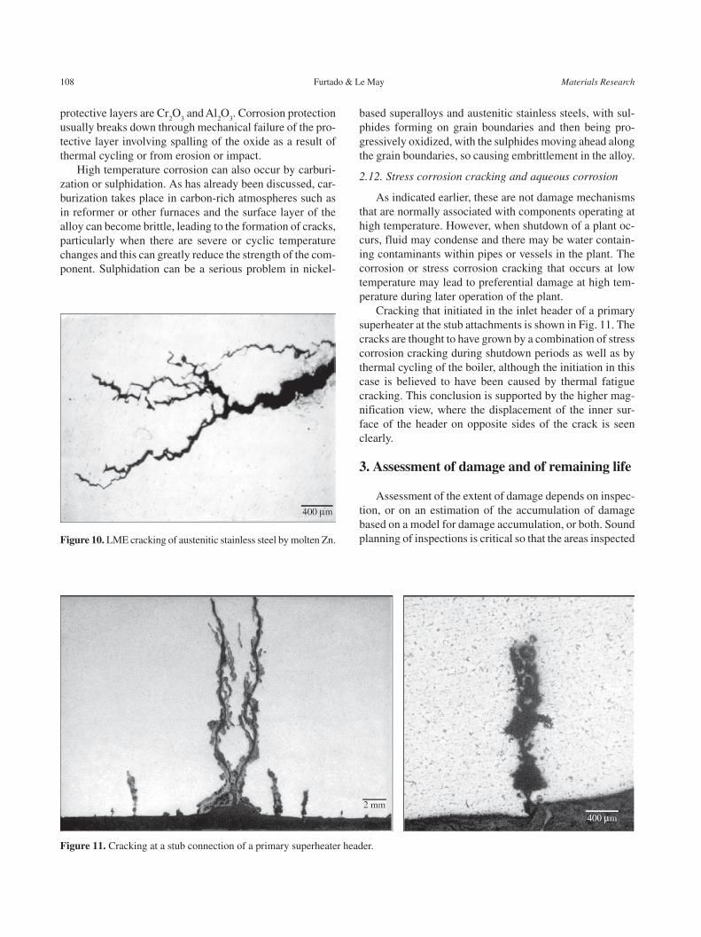
Cracking that initiated in the inlet header of a primarysuperheater at the stub attachments is shown in Fig. 11. Thecracks are thought to have grown by a combination of stresscorrosion cracking during shutdown periods as well as bythermal cycling of the boiler, although the initiation in thiscase is believed to have been caused by thermal fatiguecracking. This conclusion is supported by the higher mag-nification view, where the displacement of the inner sur-face of the header on opposite sides of the crack is seenclearly.
3. Assessment of damage and of remaining life
Assessment of the extent of damage depends on inspec-tion, or on an estimation of the accumulation of damagebased on a model for damage accumulation, or both. Soundplanning of inspections is critical so that the areas inspected
Figure 11. Cracking at a stub connection of a primary superheater header.
Figure 10. LME cracking of austenitic stainless steel by molten Zn.

Vol. 7, No. 1, 2004 High Temperature Degradation in Power Plants and Refineries 109
are those where damage is expected to accumulate and theinspection techniques used are such as will provide reliableestimates of the extent of damage. If the extent of the dam-age is known or can be estimated, a reduced strength can beascribed to the component and its adequacy to perform safelycan be calculated.
The general philosophy for estimating fitness for serviceis outlined in the American Petroleum Institute (API) Rec-ommended Practice 579, “Fitness-for-Service”, the first edi-tion of which was published in 2000. This document pro-vides assessment procedures for the various types of defectsto be expected in pressurized equipment in the refinery andchemical industry. The steps involved are as follows:
• Step 1: Identification of flaws and damage mecha-nisms.
• Step 2: Identification of the applicability of the as-sessment procedures applicable to the particular dam-age mechanism.
• Step 3: Identification of the requirements for data forthe assessment.
• Step 4: Evaluation of the acceptance of the compo-nent in accordance with the appropriate assessmenttechniques and procedures.
• Step 5: Remaining life evaluation, which may includethe evaluation of appropriate inspection intervals tomonitor the growth of damage or defects.
• Step 6: Remediation if required.• Step 7: In-service monitoring where a remaining life
or inspection interval cannot be established.• Step 8: Documentation, providing appropriate records
of the evaluation made.API 579 does not presently cover high temperature dam-
age to components operating in the creep regime, this sec-tion still being under discussion and development. It shouldbe noted in addition that the entire API 579 document isbeing re-developed in conjunction with the American Soci-ety of Mechanical Engineers (ASME) to provide a com-mon document as a Standard issued by both societies.
For equipment operating at high temperature in the creeprange, the principles outlined above are followed. Creepdamage can be assessed by various procedures includingthose described earlier. Life estimates can also be madebased on the predicted life at the temperature and stress thatare involved, by subtracting the calculated life used up, andmaking an allowance for loss of thickness by oxidation orother damage. Recently there has been increased use of theprocedures of continuum damage mechanics7 for creep dam-age and remaining life assessment. These ideas were ini-tially developed for practical use by Penny15, and have beenadvanced further by Penny and Marriott16 and through theapplication of the Omega method developed by the Materi-als Properties Council17
The growth of cracks in components operating at high
temperature that are detected can be estimated using estab-lished predictive methods as given, for example, by Websterand Ainsworth18. Additionally, various examples of simpli-fied methods to predict safe life in petrochemical plant con-taining cracks have been published, for example in a re-former furnace19.
References
1. Ashby, M.F. A First Report on Deformation-MechanismMaps, Acta Met., v. 20, p. 887-897, 1972.
2. Mohamed, F.A.; Langdon, T.G. Deformation MechanismMaps: Their Use in Predicting Creep Behavior, J. Eng.Matls. and Technol., v. 98, p. 125-130, 1976.
3. Neubauer, B.; Wedel, U. Restlife Estimation of Creep-ing Components by Means of Replicas, in ASME Inter-national Conference on Advances in Life PredictionMethods, (Eds. D.A. Woodford, J.R. Whitehead, ASME,New York, 1983).
4. da Silveira, T.L.; Le May, I. Effects of MetallographicPreparation Procedures on Creep Damage Assessment,Materials Char., v. 28, p. 75-85, 1992.
5. Samuels, L.E.; Coade, R.W.; Mann, S.D. PrecrackingStructures in a Creep-Ruptured Low-Carbon Cr-MoSteel: Their Nature and Detection by Light Microscopyand Scanning Electron Microscopy, Materials Char., v.29, p. 343-363, 1992.
6. Toft, L.H.; Marsden, R.A. The Structure and Propertiesof 1%Cr-0.5%Mo Steel After Service in CEGB PowerStations, in Structural Processes in Creep: Special Re-port 70, (Iron and Steel Institute, London, 1961).
7. Kachanov, L.M. Introduction to Continuum Damage Me-chanics, (Martinus Nijhoff, Dordrecht, 1986).
8. Dyson, B. Use of CDM in Materials Modeling and Com-ponent Creep Life Prediction, J. Pressure Vessel Technol.,v. 122, p. 281-296, 2000.
9. Furtado, H.C.; Collins, J.A.; Le May, I. Extending theReliable Operation of Ageing Power Stations ThroughAnalysis of Failed Components, in Ageing of Materialsand Methods for the Assessment of Lifetimes of Engi-neering Plant – Cape ’97, (Ed. R.K. Penny, Balkema,Rotterdam, 1996).
10. Honeycombe, R.W.K. Steels: Microstructure and Prop-erties, (Arnold, London, 1981).
11. Johnson, J.M.; Berry, M.R.; Gutzheit, J. ZincEmbrittlement of Stainless Steels, in Embritlement byLiquid and Solid Metals, (Ed. M. H. Kamdar, Met. Soc.AIME, Warrendale, 1984).
12. The Flixborough Disaster, Report of the Court of En-quiry, (Dept. of Employment, HMSO, London, 1975).
13. Kamdar, M.H. Liquid Metal Embrittlement, in MetalsHandbook, Ninth Edition, Vol. 13, Corrosion, (ASMInternational, Metals Park, 1987).

110 Furtado & Le May Materials Research
14. Cottrell, A.H.; Swann, P.R. Technical Lessons ofFlixborough, The Chemical Engineer, v. 4, p. 266-274,1976.
15. Penny, R.K. The Usefulness of Engineering DamageParameters During Creep, Metals and Materials, v. 8,p. 278-283, 1974.
16. Penny, R.K.; Marriott, D.L. Design for Creep, 2nd Edi-tion, (Chapman & Hall, London, 1995).
17. Prager, M. Development of the MPC Omega Method
for Life Assessment in the Creep Range, J. PressureVessel Technology, v. 117, p. 95-103, 1995.
18. Webster, G.A.; Ainsworth, R.A. High Temperature Com-ponent Life Assessment, (Chapman & Hall, London,1994).
19. Furtado, H.C.; Le May, I. Damage Evaluation and LifeAssessment in High Temperature Plant: Some CaseStudies, in Creep and Fatigue, (I. Mech,. E., London,1996).