Embed Size (px)
Citation preview

March 2005
NASA/TM-2005-213536
High Speed Research Program Structural Acoustics Multi-Year Summary Report Theodor H. Beier The Boeing Company, St. Louis, Missouri
Waman V. Bhat The Boeing Company, Seattle, Washington
Stephen A. Rizzi and Richard J. Silcox Langley Research Center, Hampton, Virginia
Myles A. Simpson The Boeing Company, Huntington Beach, California
https://ntrs.nasa.gov/search.jsp?R=20050111539 2018-09-06T20:32:30+00:00Z

The NASA STI Program Office . . . in Profile
Since its founding, NASA has been dedicated to the advancement of aeronautics and space science. The NASA Scientific and Technical Information (STI) Program Office plays a key part in helping NASA maintain this important role.
The NASA STI Program Office is operated by Langley Research Center, the lead center for NASA’s scientific and technical information. The NASA STI Program Office provides access to the NASA STI Database, the largest collection of aeronautical and space science STI in the world. The Program Office is also NASA’s institutional mechanism for disseminating the results of its research and development activities. These results are published by NASA in the NASA STI Report Series, which includes the following report types:
• TECHNICAL PUBLICATION. Reports of
completed research or a major significant phase of research that present the results of NASA programs and include extensive data or theoretical analysis. Includes compilations of significant scientific and technical data and information deemed to be of continuing reference value. NASA counterpart of peer-reviewed formal professional papers, but having less stringent limitations on manuscript length and extent of graphic presentations.
• TECHNICAL MEMORANDUM. Scientific
and technical findings that are preliminary or of specialized interest, e.g., quick release reports, working papers, and bibliographies that contain minimal annotation. Does not contain extensive analysis.
• CONTRACTOR REPORT. Scientific and
technical findings by NASA-sponsored contractors and grantees.
• CONFERENCE PUBLICATION. Collected
papers from scientific and technical conferences, symposia, seminars, or other meetings sponsored or co-sponsored by NASA.
• SPECIAL PUBLICATION. Scientific,
technical, or historical information from NASA programs, projects, and missions, often concerned with subjects having substantial public interest.
• TECHNICAL TRANSLATION. English-
language translations of foreign scientific and technical material pertinent to NASA’s mission.
Specialized services that complement the STI Program Office’s diverse offerings include creating custom thesauri, building customized databases, organizing and publishing research results ... even providing videos. For more information about the NASA STI Program Office, see the following: • Access the NASA STI Program Home Page at
http://www.sti.nasa.gov • E-mail your question via the Internet to
[email protected] • Fax your question to the NASA STI Help Desk
at (301) 621-0134 • Phone the NASA STI Help Desk at
(301) 621-0390 • Write to:
NASA STI Help Desk NASA Center for AeroSpace Information 7121 Standard Drive Hanover, MD 21076-1320

National Aeronautics and Space Administration Langley Research Center Hampton, Virginia 23681-2199
March 2005
NASA/TM-2005-213536
High Speed Research Program Structural Acoustics Multi-Year Summary Report Theodor H. Beier The Boeing Company, St. Louis, Missouri
Waman V. Bhat The Boeing Company, Seattle, Washington
Stephen A. Rizzi and Richard J. Silcox Langley Research Center, Hampton, Virginia
Myles A. Simpson The Boeing Company, Huntington Beach, California
Available from: NASA Center for AeroSpace Information (CASI) National Technical Information Service (NTIS) 7121 Standard Drive 5285 Port Royal Road Hanover, MD 21076-1320 Springfield, VA 22161-2171 (301) 621-0390 (703) 605-6000
Acknowledgments
Several individuals contributed to this report. These include Mike Andre (Boeing), Waman Bhat (Boeing), Gary Gibbs (NASA Langley), Hugh Poling (Boeing), Robert Rackl (Boeing), Steve Rizzi (NASA Langley), Rich Silcox (NASA Langley), Myles Simpson (Boeing), and Jaak Soovere (Lockheed Martin). Ted Beier (Boeing), Paul Heaton (Boeing), and Steve Rizzi prepared a previous sonic fatigue report from which much of the relevant material in this document was abstracted. Myles Simpson assembled and edited the report.
The use of trademarks or names of manufacturers in the report is for accurate reporting and does not constitute an official endorsement, either expressed or implied, of such products or manufacturers by the National Aeronautics and Space Administration.

iii
PREFACE This report was prepared by the Structural Acoustics ITD Team under Task 49 of NASA's High Speed Research (HSR) Program, and summarizes the work conducted during the HSR Phase II program from 1993 to 1999 on Tasks 27 and 49. The report is intended to be a reference for future researchers to the results of the interior noise and sonic fatigue technology development activities conducted during this period. The work of the Structural Acoustics ITD Team encompassed numerous modeling, testing, and demonstration tasks. Although all the Team members were involved to some extent on all of the tasks, the Team was structured such that specific groups had responsibility for certain activities. On the industry side, the Boeing Commercial Airplane group in Seattle was responsible for boundary layer modeling, passive noise control techniques, structural-acoustic modeling with energy-based methods, jet noise modeling, the Tu-144 cabin noise flight tests, and technology integration. Lockheed-Martin in Atlanta provided support for the passive noise control work, particularly in the area of finite-element modeling. The Boeing Phantom Works group in Long Beach was responsible for structural-acoustic model development using the MDE code, the supersonic wind tunnel test program, HSCT interior noise and weight penalty estimates, and the early active noise control technology development activities. The Boeing Phantom Works group in St. Louis was responsible for the sonic fatigue technology activities. On the government side, NASA Langley was responsible for boundary layer-structure interaction modeling, active noise control technology development, sonic fatigue methods development, sonic fatigue component testing, noise control optimization, Tu-144 flight test and data analysis support, and the overall Structural Acoustics program leadership.

iv
TABLE OF CONTENTS
1. Executive Summary ................................................................................................ 1
2. Objectives................................................................................................................. 3
3. Goals......................................................................................................................... 4 3.1. Performance Targets ..............................................................................................4 3.2. Definition and Target of Technology Readiness Levels ........................................4
4. Approach ................................................................................................................. 5 4.1. Sources of Excitation .............................................................................................5
4.1.1. Turbulent Boundary Layer Pressure Fluctuations..........................................5 4.1.2. Near Field Jet Noise.......................................................................................6 4.1.3. Inlet Noise ......................................................................................................7
4.2. Structural Acoustic Modeling ................................................................................7 4.2.1. The Matrix Difference Equation (MDE) Method ..........................................7 4.2.2. COMET/Acoustic Modeling..........................................................................8 4.2.3. AutoSEA........................................................................................................8
4.3. Passive Treatments.................................................................................................9 4.4. Active Controls ......................................................................................................9 4.5. HSCT Interior Noise Predictions .........................................................................10
4.5.1. MD-80-Based Predictions............................................................................10 4.5.2. Concorde-Based Predictions ........................................................................11
4.6. Sonic Fatigue Overview.......................................................................................11
5. Technology Development ..................................................................................... 13 5.1. Sources of Excitation ...........................................................................................13
5.1.1. Turbulent Boundary Layer Pressure Fluctuations........................................13 5.1.2. Near Field Jet Noise.....................................................................................16 5.1.3. Inlet Noise ....................................................................................................17
5.2. Structural Acoustic Modeling ..............................................................................18 5.2.1. The Matrix Difference Equation (MDE) Method ........................................18 5.2.2. MDE Validation Studies ..............................................................................19 5.2.3. COMET/Acoustics Modeling ......................................................................21 5.2.4. AutoSEA......................................................................................................22
5.3. Passive Treatments...............................................................................................22 5.3.1. Trim and Insulation......................................................................................23 5.3.2. Primary Structure .........................................................................................26 5.3.3. Status............................................................................................................28
5.4. Active Controls ....................................................................................................29 5.4.1. Active Structural Acoustic Control Tests and Results.................................30 5.4.2. Smart Foam Tests and Results.....................................................................31 5.4.3. Status............................................................................................................33
5.5. HSCT Interior Noise Predictions .........................................................................34 5.5.1. MD-80-Based Predictions............................................................................34 5.5.2. Concorde-Based Predictions ........................................................................35
v
5.6. Sonic Fatigue .......................................................................................................36 5.6.1. Loads Prediction ..........................................................................................36 5.6.2. Materials Characterization ...........................................................................36 5.6.3. Sonic Fatigue Code Development................................................................38 5.6.4. Response Reduction Techniques .................................................................39 5.6.5. Sonic Fatigue Design Requirements ............................................................39
6. Summary of Results .............................................................................................. 41 6.1. Interior Noise .......................................................................................................41 6.2. Sonic Fatigue .......................................................................................................42
7. Lessons Learned and Recommendations for the Future................................... 44 7.1. Programmatic.......................................................................................................44 7.2. Technical..............................................................................................................45
7.2.1. Interior Noise ...............................................................................................45 7.2.2. Sonic Fatigue ...............................................................................................47
8. Bibliography .......................................................................................................... 48 8.1. Interior Noise .......................................................................................................48 8.2. Sonic Fatigue .......................................................................................................51
vi
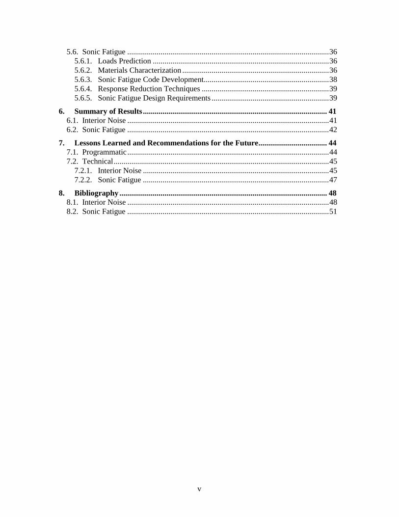
LIST OF TABLES Table 1: High Cycle Fatigue Test Summary...................................................................37
LIST OF FIGURES
Figure 1: The Concorde and Tu-144 Flight Test Conditions...........................................14
Figure 2: Comparison of Tu-144 Based Prediction of Auto-Spectra with the Concorde Data ..........................................................................................................................15
Figure 3: Tu-144 Data vs. Preliminary HSCT Design Spectra .......................................18
Figure 4: Comparison of Measured and Predicted Sound Power Reduction, Composite Skin-Stringer Panel, Mach 2.5 .................................................................................20
Figure 5: Radiated Sound Power Autospectrum of Bay 1 Estimate Using Radiation Filters, Two Bay Control, 2.5M...............................................................................31
Figure 6: Photograph of Smart Foam Actuator Element ................................................32
Figure 7: Smart Foam Control Results for Mach 0.8, Active Control Bandwidth is 400 – 800 Hz......................................................................................................................33
Figure 8: Estimated Interior Noise Levels and Weight Penalties ....................................35
Figure 9: Predicted Interior Noise Levels for Pathfinder Design at Key Flight Conditions..................................................................................................................................36
Figure 10: Sonic Fatigue Analysis Interim and Final Processes .....................................38

1
HSR STRUCTURAL ACOUSTICS MULTI-YEAR SUMMARY REPORT
1. Executive Summary This report documents the major accomplishments and lessons learned of the Structural Acoustics program during the course of the High Speed Research Program. The scope of the Structural Acoustics work effort included two separate but related technology areas, interior noise and sonic fatigue. The aeroacoustic loads on the HSCT vehicle are common to both technologies. The interior noise technology activities were concerned with the passenger cabin noise levels which result from these loads, while the sonic fatigue technology activities were concerned with the response of the HSCT structure to these loads. An overall strategy for both technology areas was established early in the program. During the PCD1 period, activities were to be oriented towards assessing the magnitude of the structural acoustics issues (i.e. excessive passenger cabin noise levels and excessive sonic fatigue loads), identifying technology requirements to resolve these issues, and beginning the development of these technologies. During the PCD2 period, technology development activities were to be completed, and the technologies were to be validated and demonstrated. Technology integration activities were planned for PCD3 period. As a result of budget reductions at several times, some of the technology development, validation, and demonstration activities were not fully completed during the PCD2 period. With the termination of the HSR program early in the PCD3 period, the remaining technology development activities and most of the technology integration activities were not conducted. An emphasis throughout the program was placed on tracking progress towards meeting specified relevant program metrics. For the Structural Acoustics program, the metrics selected were the weight penalties of additional treatments that would be needed to achieve the desired interior noise and sonic fatigue goals. As described in Section 3, for interior noise the target weight penalty is 0 lb/ft2, and for sonic fatigue the target weight penalty is 0.1 lb/ft2. With the early termination of the HSR program, the current values of these metrics are an interior noise penalty of 0.3 lb/ft2 (for a skin-stringer fuselage) and a sonic fatigue weight penalty of 0.5 lb/ft2. Despite the premature conclusion of the Structural Acoustics program, an extensive amount of valuable work has been completed to date, which is the subject in this report. The next two sections of this document describe the Objectives and Goals of the Structural Acoustics program. Section 4 provides an overview of the approach used to achieve these objectives and goals, which set the direction of the technical activities that were conducted throughout the program. Section 5 discusses the various technology development activities, with emphasis on the major results achieved. Sections 6 and 7 summarize the results and list lessons learned, while Section 8 provides a bibliography
2
with references to the more detailed technical documents that have been generated during this program. A separate and comprehensive multi-year summary report [S-1]* on the sonic fatigue portion of the HSR Structural Acoustics program was written following the termination of the sonic fatigue effort in November 1998, but prior to the cancellation of the HSR program. The report serves the same purpose as this multi-year summary report. This current document therefore contains only the highest level information on the sonic fatigue work. The reader should refer to [S-1] for more detailed information. _______________________ * References are listed in Section 8, separately for Interior Noise and Sonic Fatigue. The reference numbers in the text are denoted as [I-x] and [S-x], respectively.

3
2. Objectives Passenger comfort is critical to the acceptance and economic success of a High Speed Civil Transport (HSCT) aircraft. To ensure an acceptable interior acoustic environment, the effects of high exterior aeroacoustic loads resulting from the supersonic turbulent boundary layer and the jet engines must be minimized. The exterior acoustic environment is particularly severe in the vicinity of the engines, hence special care must be taken to select airframe structural concepts which are tolerant of the high acoustic loads. As a result of these considerations, the overall objectives of the Structural Acoustics technology area were to: • Develop and experimentally validate computational models for predicting the
interaction of flexible structures with jet and boundary layer aeroacoustic loads, • Develop and experimentally validate methods for noise transmission prediction and
noise control for HSCT fuselage structural concepts and loads, and • Develop an experimental database of acoustic response and fatigue characteristics for
HSCT materials and structural concepts.

4
3. Goals
3.1. Performance Targets The interior noise goal is to provide interior noise levels comparable to those of current new subsonic transport aircraft. This translates into the following target interior noise levels: • An average A-weighted noise level of 78 dBA, arithmetically averaged over all
passenger seats, and • A maximum A-weighted noise level 85 dBA, not to be exceeded at any seat. The goal of the sonic fatigue effort is a sonic fatigue structural life that is also comparable to that of current new subsonic transport aircraft. This translates into a target life that meets a 60,000-hour requirement with a scatter factor of 2. To achieve these interior noise and sonic fatigue goals will require the use of treatments and/or techniques that may add weight to the vehicle. Any weight over the weight normally required in conventional subsonic aircraft is termed a "weight penalty," expressed in pounds per square foot of effected fuselage surface area. For interior noise, the target weight penalty is zero, while for sonic fatigue the target weight penalty is 0.1 lb/ft2.
3.2. Definition and Target of Technology Readiness Levels NASA uses a Technology Readiness Level (TRL) scale to rate the maturity of a technology under development. The scale is as follows:
9: Actual system "flight proven" on operational flight 8: Actual system completed and "flight qualified" through test and
demonstration 7: System prototype demonstrated in flight 6: System/subsystem model or prototype demonstrated in a relevant
environment 5: Component (or breadboard) validation in a relevant environment 4: Component and/or breadboard validation in a laboratory environment 3: Analytical & experimental critical function and/or characteristic proof-of-
concept 2: Technology concept and/or application formulated 1: Basic principles observed and reported
The target for the Structural Acoustics program is development of technology to a TRL of 5. This requires a validation at the component level, in a relevant environment (such as a wind tunnel or flight test vehicle).

5
4. Approach The approach used to achieve the objectives and goals described above was to conduct the following activities: • Develop aeroacoustic loads models based on fluctuating pressure data obtained from
flight tests, and near field acoustic jet loads data obtained from wind tunnel tests, • Develop interior noise prediction models and validate them through transmission loss
tests, supersonic wind tunnel tests, and flight tests, • Develop passive and active noise control technologies and validate them in
supersonic wind tunnel tests, • Conduct high cycle vibratory sonic fatigue coupon tests of various candidate HSCT
materials, and • Validate sonic fatigue analysis methods through acoustic response and fatigue tests in
a high intensity thermal acoustic progressive wave tube facility. In addition to these activities, progress towards achieving the interior noise and sonic fatigue performance targets was tracked periodically throughout the program (typically on an annual basis). For interior noise, preliminary cabin noise prediction models were developed and used to assess the status of estimated interior noise levels over time. These various activities are described in greater detail in the following sections.
4.1. Sources of Excitation
There are two primary external sources of excitation of the fuselage structure that impact interior noise levels, the turbulent boundary layer pressure fluctuations which form as the HSCT moves through the atmosphere, and the jet noise produced by the aircraft's engines which impacts the fuselage structure aft of the engines. The engines also generate high noise levels at their inlets, but this is not a source of cabin noise. (High inlet and jet exhaust noise are important sources of sonic fatigue on wing and engine structure; this will be discussed separately in the sonic fatigue sections.)
4.1.1. Turbulent Boundary Layer Pressure Fluctuations
In all modern high-speed jet engine powered aircraft the turbulent boundary layer (TBL) pressure fluctuations on the outside fuselage are the main source of the cabin noise. Due to higher aircraft speeds TBL excitation is likely to become an even more important source of HSCT cabin noise. TBL pressure fluctuations, when combined with the near field engine noise on the fuselage aft section, also become a significant source of sonic fatigue loads. To successfully deal with cabin noise, advanced models to predict TBL excitation spectra and cross-spectra for supersonic flow conditions were needed. Most of the existing models were based on measurements in the subsonic flow regime.

6
Models for supersonic flow were generally based on measurements in wind tunnels or on small supersonic aircraft. Thus, collecting data on large supersonic aircraft and using it to develop models that can be applicable at large Reynolds numbers was considered essential for developing experimentally verified, and hence credible, supersonic TBL pressure fluctuation models. Further, a fully coupled fluid-structural-acoustic model is desired to provide a full understanding of the effects of high speed flow and boundary layer on panel dynamics, damping and coupling to the interior cabin space. Areas of accelerating and decelerating flow are shown to have a significant impact on interior noise and unsteady shocks are a source of interior noise and fatigue failures in aerospace structures. Present computer technology will provide only simplified models of this phenomenon but the future growth of computer capacity will make possible practical computational tools.
4.1.2. Near Field Jet Noise
Structures in the vicinity of the engine exhaust nozzles are exposed to intense noise radiation from the exhaust flow. The strongest exposure occurs during takeoff and subsonic climb out. Subsonic cruise segments may also be important. During supersonic cruise the sound waves do not have a chance to reach aircraft structures as they are swept downstream unless some portions of the tail are very close to or in the exhaust flow. Near field jet noise is an important load to be considered in sonic fatigue resistance of rear fuselage and tail structures; exposure of wing surfaces near the engines may also have to be predicted. The rear portion of the passenger cabin experiences elevated interior noise levels due to near field jet noise which need to be predicted and combined with other noise sources. A community noise prediction model for a mixer/ejector nozzle had already been developed which, fortunately, already incorporated near field features since the jet noise sources are distributed over a length of many exhaust nozzle diameters. This needs to be taken into account for small distance community noise test points such as the FAR 36 approach point, and for the application of a model to predict acoustic shielding of one jet by another, and by the fuselage and wing. The model also already included the effect of a boundary layer over a cylindrical surface on acoustic wave propagation. What was missing was such an effect over a flat surface (i.e., wing). From the computer code of the community noise model, the near field portions were culled, and this boundary layer effect over a flat surface was incorporated.

7
4.1.3. Inlet Noise
Predicted overall sound pressure level noise contours and spectrum shapes on the fuselage and wing surfaces due to engine inlet noise propagation were based on measured data from supersonic tactical aircraft. These acoustic levels were used for preliminary sonic fatigue calculations on the lower surface of the wing and strake to determine required structural sizing. Flight test data from the Tu-144 flight program were analyzed and compared to these predictions.
4.2. Structural Acoustic Modeling
To estimate cabin noise levels in the HSCT, structural acoustic models were developed. These models incorporate an explicit prediction of the excitation field on the fuselage structure (from the turbulent boundary layer and the engines), the vibration response of the structure to this excitation, and the resulting acoustic field radiated into the cabin. Two primary approaches to modeling were studied, one based on a finite element methods (FEM) and one based on statistical energy analysis (SEA) methods. Typically finite element methods provide better predictions of structural response in the low to mid frequency portion of the spectrum, while energy-based methods provide better predictions in the mid to high frequency portion of the spectrum. The prediction accuracy of finite element models is dependent on structural and flow parameters, such as panel dimensions, mode order, wavelength, Mach number, frequency, etc. To obtain good accuracy in predicting structural response with finite element codes, the size of the smallest element must be a fraction of the wavelengths of the acoustic excitation and vibration fields. From a practical perspective, considering computer limitations and modeling effort, a typical sidewall panel model can be reasonably divided into elements as small as one inch, and therefore predictions are likely to be valid for acoustic wavelengths as short as four inches and up to 2000 Hz for Mach 2.4 flow excitation [I-1].
4.2.1. The Matrix Difference Equation (MDE) Method The MDE method is a finite element based approach to compute aircraft cabin interior noise levels resulting from external sources [I-2], [I-3]. The MDE method overcomes many of the disadvantages associated with conventional finite element methods by using innovative modeling of both the fuselage and the acoustic cavity. The MDE method uses a simplifying assumption that the structural geometry is spatially periodic, composed of identical substructures arranged along an axis. This assumption is certainly valid for an aircraft fuselage, which is composed of many nearly-identical longitudinal subcomponents bounded by the frames. The benefits of this periodic assumption are that: (1) the orders of the assembled mass and stiffness matrices are equal to the number of degrees of freedom on one boundary between substructures instead of being equal to the number of degrees of freedom in the complete model, and (2) that the user models only one substructure. As a result the computing cost associated with an MDE
8
model is substantially lower than for a conventional FEM model, and data preparation time is also reduced. The non-periodic features in an otherwise periodic model can be easily incorporated by using a modification program available in the MDE code. To apply the MDE method to the HSCT several modifications and improvements to the MDE code were implemented, including development of various composite elements into the MDE library and incorporation of a spectral analysis capability to permit excitation of the structure by a turbulent boundary layer. A major undertaking during the HSR Structural Acoustics program was a series of supersonic wind tunnel tests. The purpose of these tests was to measure the response of candidate fuselage sidewall panels to supersonic and high subsonic boundary layer excitation, to obtain validation data in a relevant test environment. The first phase of the wind tunnel tests was conducted to obtain data with which the MDE prediction method could be validated. The second phase was conducted to obtain data with which various passive and active noise control techniques could be validated. Additional validation of the MDE method was undertaken using fuselage structural response data acquired on the Tu-144 aircraft during supersonic flight tests. 4.2.2. COMET/Acoustic Modeling COMET/Acoustics is a commercial Finite Element and Boundary Element structural acoustic prediction code from Automated Analysis Corporation of Ann Arbor, Michigan. Although it has an internal finite element structural capability, it integrates well with MSC NASTRAN (as well as with other commercial codes) to allow more complicated structural geometries to be modeled. This model may then be fully coupled to either FEM or BEM models of the acoustic spaces. For this effort, the noise transmission characteristics of a curved honeycomb composite sidewall panel was examined analytically and validated by experimental modal analysis and transmission loss testing [I-4]. The simulations were run using random or reverberant excitation, the details of which are also discussed.
4.2.3. AutoSEA
The AutoSEA (version 1.5) tool is an implementation of SEA (Statistical Energy Analysis), a method for tracing energy flow through a network of connected elements representing a physical system. AutoSEA is a commercially available code [I-5]. The key use of AutoSEA in the HSR Structural Acoustics activities was to calculate the transmission loss of proposed fuselage sidewall designs. The transmission loss was used as a ranking metric describing the acoustic

9
performance of sidewall designs. Transmission loss tests of several panels were used to validate the AutoSEA results, examples of which are discussed in [I-6]. AutoSEA is also the engine for a Matlab-based sidewall design optimization tool [I-7]. Although it was developed late in the program and thus not available for design decisions, it does illustrate a disciplined approach to optimizing acoustic performance.
4.3. Passive Treatments
High Speed Civil Transport interior noise levels are expected to exceed current design goals by as much as 10 dBA in some areas of the passenger cabin when typical subsonic transport noise control methods are employed. Applying typical subsonic noise control methods to reduce HSCT interior levels will result in an unacceptable weight penalty. Therefore, noise control techniques for the HSCT must provide more noise reduction per treatment weight than subsonic methods.
The effort to improve and develop innovative passive noise control methods has followed a methodical plan to improve noise control treatments through testing and analytical modeling. Generally, the plan has followed these steps: 1) Develop a list of possible HSCT noise control treatments: search literature,
brainstorm, etc. 2) Select most promising from step 1 and perform structural acoustic testing. Also
test the candidate composite fuselage structural designs (skin/stringer and honeycomb).
3) Use the test database of step 2 to verify analytical models: finite element models (MDE, NASTRAN), statistical energy models (AutoSEA), etc.
4) Use verified models of step 3 to develop better noise control treatments. 5) Perform structural acoustic testing of the best step 4 acoustic treatments. 6) Use the step 5 test data to re-verify analytical models and use models to
understand what happens when treatments are combined. 7) Select the best treatment combination for the HSCT.
At the beginning of PCD2, it was thought that the above steps could be completed in 3 to 4 years. However, at this point in time most of the passive controls work has not made it past step 3. The exception is some aspects of the primary structure passive controls that have progressed into step 4. 4.4. Active Controls
Active noise control technology has been developed in recent years to the point where it is installed in commercial aircraft to control harmonic noise sources. These include engine shaft rotation tones in the rear cabin of commercial jets as well as propeller tones in the interior of turboprop powered aircraft. Applications to broadband noise sources are confined to a few niche markets such as noise in HVAC ducts and in industrial compressor systems.

10
For HSR, the dominant interior noise sources are boundary layer and jet exhaust excited fuselage wall vibrations which then radiate broadband noise to the interior cabin space. For this application, where the vibration source is broadband and ranging from somewhat to fully uncorrelated in time and space, a more distributed control approach is required typically also requiring a feedback control topology. As each aircraft panel vibrates independently of its neighbors, the control system must respond individually to the response of the resonant structural modes of each panel, themselves functions of temperature and pressurization. Thus the development effort, while still dependent on the authority and bandwidth of actuators, focused on the development of suitable control algorithms and novel control schemes that could utilize simpler control methods. In addition, passive-active control approaches were investigated that combined the fail-safe properties of passive damping with the capability of active systems to reduce resonant responses.
4.5. HSCT Interior Noise Predictions
Given the interior noise goal and target levels discussed above, it was clear early in the program that a methodology was needed to estimate HSCT interior noise levels. This methodology would be critical in defining the amount of noise reduction needed to meet the target interior noise levels, and to estimate the associated weight penalties of the noise control treatments required to obtain the needed noise reductions. Since the development and validation of the planned structural acoustic prediction codes had not yet been completed, the approach taken for estimating HSCT interior noise levels was to take advantage of available flight test data, and to extrapolate the measured noise levels to the HSCT structural design and flight conditions. Two independent methods were developed. The first is based on detailed measurements taken on an MD-80. In this case, detailed information on the structure was available to develop a good understanding of its noise reduction characteristics and the implied external noise source, but the flight Mach number was limited to subsonic. The second approach used a small set of measurements taken on the Concorde with Mach number up to 2.0. These data are limited by lack of structural information, which increases uncertainty on the noise reduction needed to derive the external source.
4.5.1. MD-80-Based Predictions
Cabin noise levels were measured in prior flight tests on an MD-80 aircraft during normal cruise operations. Simultaneous measurements of the turbulent boundary layer pressure fluctuations on the fuselage surface had also been obtained. Using the measured exterior and interior noise data, adjustments were made for changes in the turbulent boundary layer loads (due to higher speeds and altitude) and for changes in the sidewall transmission (due to the use of composite rather than

11
aluminum construction). In the aft portion of the aircraft, acoustic loads from engine sources were also included in the exterior excitation. From the adjusted data the interior noise levels in the HSCT were estimated, as a function of fuselage length. For those locations where estimated noise levels exceeded target levels, conventional passive noise control treatments where added such that the resulting noise reduction would bring the original estimated levels to the target levels. Then the weight of the noise control treatments was estimated, and a weight penalty was determined. This approach was used throughout the program to assess the change in HSCT interior noise levels and weight penalties as the transmission loss characteristics of the various composite sidewall designs were determined.
4.5.2. Concorde-Based Predictions
Measurement of noise levels at window and aisle seats were available for the Concorde during supersonic and subsonic flights. Assuming that boundary layer noise is the dominant source, these measured levels were adjusted for changes in source levels and noise reduction through the sidewall to arrive at an HSCT prediction. The source adjustment was based on the Efimstov Turbulent Boundary Layer model [I-8]. Predicted 1/3-octave-band spectra for the Concorde flight condition at each measurement location (distance from nose) were subtracted from predicted spectra at the HSCT flight condition and seat location. This increment was added to the Concorde measurement as an estimate of what would have been measured if the Concorde were as large as the HSCT and flown at HSCT conditions. Since the HSCT will be constructed differently than the Concorde, differences in noise attenuation through the fuselage sidewall were included in the prediction process. The difference in transmission loss between the Concorde and HSCT sidewalls was added to the Concorde measurements to simulate the result of building the Concorde fuselage like the proposed HSCT.
4.6. Sonic Fatigue Overview In order to meet the sonic fatigue goal indicated in Section 3.1, a number of elements were targeted for technology development. These included: • Prediction of inlet, exhaust and boundary layer acoustic loads, • Measurement of high cycle fatigue data for materials developed during the HSR
program, • Development of advanced sonic fatigue calculation methods to reduce required
conservatism in airframe designs,

12
• Development of damping techniques for sonic fatigue reduction where weight effective, and
• Development of wing and fuselage sonic fatigue design requirements. Each of these elements is discussed in further detail in Section 5.

13
5. Technology Development
5.1. Sources of Excitation
5.1.1. Turbulent Boundary Layer Pressure Fluctuations
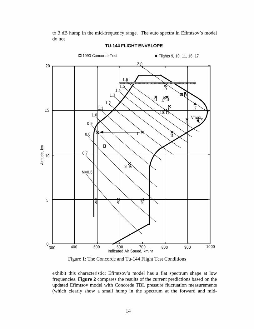
Pressure Fluctuation Modeling Two studies on turbulent boundary layer (TBL) pressure fluctuations conducted outside the HSR program provided a starting point for the Structural Acoustics activities. In the first, TBL pressure fluctuations on the outside of windows and passenger seat cabin noise were measured during flight tests on a Concorde aircraft. Four window blanks were used; measurements were made covering the Reynolds number range available on that airplane. Details of these tests in [I-9]. A TBL pressure fluctuation model was developed based on these data [I-10]. In the second, Prof. Boris Efimtsov, who is an expert in TBL pressure fluctuation modeling at TsAGI, in Moscow, Russia, developed a model based on extensive Russian wind tunnel and airplane flight test measurements. Efimtsov’s model is presented in [I-8]. The Efimtsov and Concorde-based models predicted auto- and cross-spectra for TBL pressure fluctuations. Overall the two models compared well. However, since the Efimtsov model was based on a more extensive collection of data, it was considered more generally applicable. In 1994 it was recognized that it would be highly desirable to extend the TBL pressure fluctuation database by making additional measurements on the Tu-144 airplane. A flight test program was proposed, which was not started until 1997. In this program, flush pressure transducers were installed in seven window blanks extending the full length of the aircraft. Measurements were made over the entire Tu-144 operating flight regime covering a range of Mach numbers from 0.65 to 2.0, and altitudes from 5 to 18 km. A premier data acquisition system for measuring TBL pressure fluctuations, structural vibrations and noise in the cabin was built and installed. In these tests special care was taken to ensure the flushness of the exterior pressure fluctuation transducers. These flight test data were collected till early 1998 and the tests are documented in [I-11] and [I-12]. Figure 1 shows the Tu-144 flight envelope with test conditions for both the Concorde and Tu-144 airplane tests. The Tu-144 TBL pressure fluctuations data were used to verify and improve upon Efimtsov’s model [I-13]. The Tu-144 and Concorde measurements both show a hump in the spectra, particularly at the forward and mid-section fuselage locations. Thus, the improved model of TBL auto-spectra incorporates a small 2
14
to 3 dB hump in the mid-frequency range. The auto spectra in Efimtsov’s model do not
300 400 500 600 700 800 900 1000
5
0
10
15
20
Alti
tude
, km
Indicated Air Speed, km/hr
M=0.6
0.7
0.8
0.9
1.0
1.11.2
1.31.4
1.5
1.6
2.0
Vmaxe
TU-144 FLIGHT ENVELOPE
1993 Concorde Test
10
10, 1711
11
11
1111
9, 16
999
Flights 9, 10, 11, 16, 17
111717
17
Figure 1: The Concorde and Tu-144 Flight Test Conditions
exhibit this characteristic: Efimtsov’s model has a flat spectrum shape at low frequencies. Figure 2 compares the results of the current predictions based on the updated Efimtsov model with Concorde TBL pressure fluctuation measurements (which clearly show a small hump in the spectrum at the forward and mid-

15
fuselage locations), and are considered to support the modifications to Efimtsov’s auto-spectrum shape. Analysis of the Tu-144 cross-spectrum data validated Efimtsov’s cross-spectrum model, and thus no modifications to this portion of the model were made.
No Corcos Correction Added to Measured Data
Figure 2: Comparison of Tu-144 Based Prediction of Auto-Spectra with the Concorde Data

16
A follow-on series of experiments on the Tu-144 was conducted during the period from September 1998 to April 1999 [I-14]. The purpose of these experiments was to collect local flow direction data, assess the effects of transducer flushness, and study the effects of forward and aft facing steps on turbulent boundary layer pressure fluctuations. Do to the early termination of the HSR program, the data was reduced but not otherwise analyzed. Fluid-Structure Coupling Modeling In order to provide an understanding of the physics of the coupled fluid-structural-acoustic problem of high speed boundary layer excited fuselage panel vibration and the resulting cabin acoustic levels, a mathematical model and computer code were developed [I-15], [I-16]. The turbulent boundary layer model was derived using a triple decomposition of the flow variables and applying conditional averaging to the resulting equations. Linearized panel and acoustic radiation equations were used. Results from this model were compared to experimental panel displacement results with good comparisons obtained for the lowest order panel modes which dominated the response. For the acoustic radiation, the comparison between prediction and experiment was good up to approximately 5kHz, where the discretization of the numerical model begins to break down. It should be noted that the frequencies that are critical for the structural response extend up to about 2kHz for which there was good general agreement. It is shown that in the supersonic regime, full coupling of the flexible panel leads to lower response and radiation from the panel. This effect is evident across the frequency range examined, up to 4kHz. This is believed to be due to an increase in acoustic damping on the panel. Increasing the Mach number increases the acoustic damping, which is in agreement with earlier work [I-17]. It has also been shown that a flexible panel excited by a supersonic flow with an adverse pressure gradient responses more than a panel in the same flow but with a favorable pressure gradient. Increasing the Reynolds number was found to increase the loading on the panel and therefore the panel response and radiation. An increase in boundary layer thickness is found to decrease the level of the TBL pressure fluctuations above approximately 5kHz and therefore the panel response and radiation at these frequencies but at lower frequencies there is no discernable effect. Unfortunately, comparisons were not made with the flight test and wind tunnel test data collected later in the program.
5.1.2. Near Field Jet Noise An existing community noise prediction model, called JN8, for a mixer/ejector nozzle already had near field features: noise sources are broken down into those inside and outside of the ejector. Those outside are distributed continuously along the jet axis with each point on the axis associated with a particular frequency.
17
While this is not a completely faithful model of the actual physical processes it serves well enough in identifying principal locations of noise sources when broken down into third-octave bands. When predicting the sound at a receiver location, this line source is broken down into several portions. Sound is propagated from each portion to the receiver separately and combined there. During propagation, the sound encounters flow velocity gradients in boundary layers over fuselage, wings, and empennage. The gradients bend the waves which leads to constructive and destructive wave interference patterns on the structural surfaces where the sound prediction is required. All required features for a near field jet noise model were already present except the effect of a boundary layer over a flat surface. While implementing this feature into the computer code difficulties were encountered while numerically integrating across a singularity in the mathematical equations. This was solved by use of a Frobenius series representation. Flat surfaces are modeled as infinite flat planes, and cylindrical surfaces are modeled as infinite cylinders. The final model was dubbed ‘JN8NR’; it has the following capabilities: • Predicts near field jet noise only for a mixer/ejector configuration, round or
rectangular; simple or co-annular configurations are not supported. • Prediction of shock-associated noise based on an axisymmetric model which
is assumed to apply (without proof or verification) to the rectangular nozzle • Effect of acoustic shielding of one jet exhaust flow by another • Effect of refraction of sound waves in boundary layer flows over cylindrical
(fuselage, nacelles) and flat (wings, stabilizers) surfaces
5.1.3. Inlet Noise
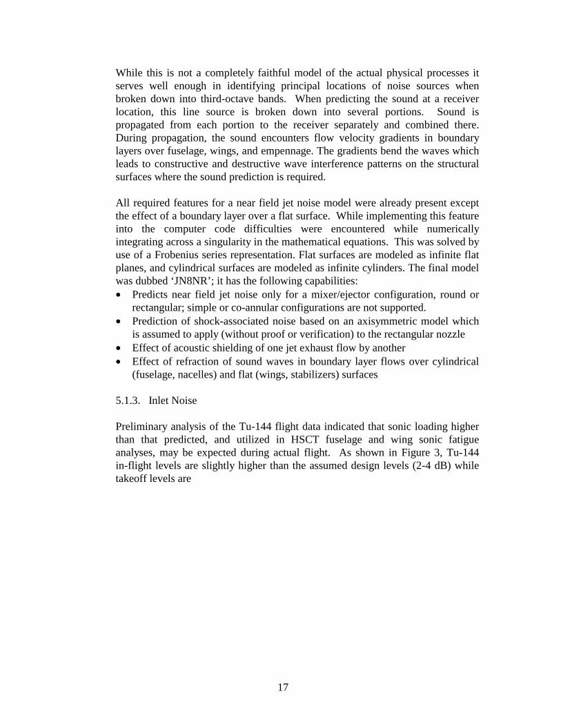
Preliminary analysis of the Tu-144 flight data indicated that sonic loading higher than that predicted, and utilized in HSCT fuselage and wing sonic fatigue analyses, may be expected during actual flight. As shown in Figure 3, Tu-144 in-flight levels are slightly higher than the assumed design levels (2-4 dB) while takeoff levels are
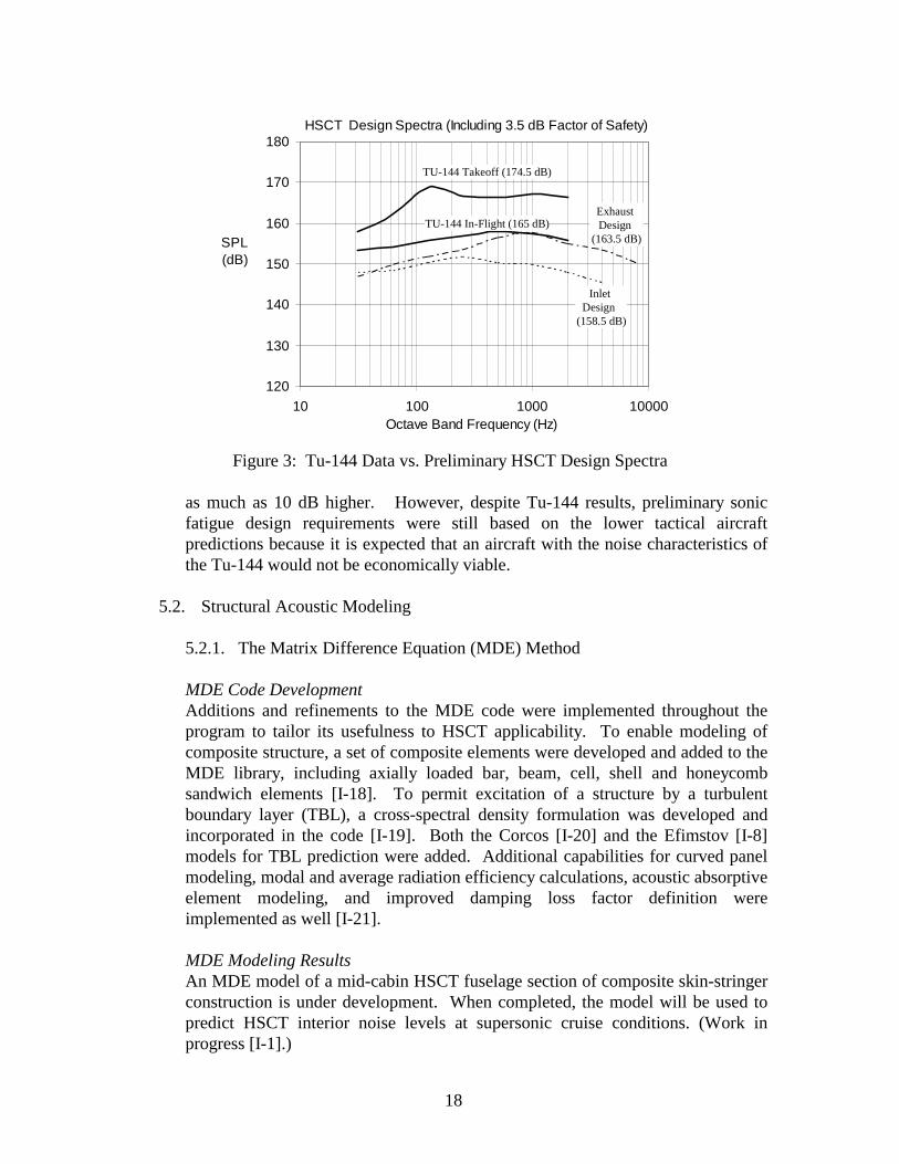
18
HSCT Design Spectra (Including 3.5 dB Factor of Safety)
120
130
140
150
160
170
180
10 100 1000 10000Octave Band Frequency (Hz)
SPL (dB)
TU-144 Takeoff (174.5 dB)
TU-144 In-Flight (165 dB)Exhaust Design
(163.5 dB)
Inlet Design
(158.5 dB)
Figure 3: Tu-144 Data vs. Preliminary HSCT Design Spectra
as much as 10 dB higher. However, despite Tu-144 results, preliminary sonic fatigue design requirements were still based on the lower tactical aircraft predictions because it is expected that an aircraft with the noise characteristics of the Tu-144 would not be economically viable.
5.2. Structural Acoustic Modeling
5.2.1. The Matrix Difference Equation (MDE) Method MDE Code Development Additions and refinements to the MDE code were implemented throughout the program to tailor its usefulness to HSCT applicability. To enable modeling of composite structure, a set of composite elements were developed and added to the MDE library, including axially loaded bar, beam, cell, shell and honeycomb sandwich elements [I-18]. To permit excitation of a structure by a turbulent boundary layer (TBL), a cross-spectral density formulation was developed and incorporated in the code [I-19]. Both the Corcos [I-20] and the Efimstov [I-8] models for TBL prediction were added. Additional capabilities for curved panel modeling, modal and average radiation efficiency calculations, acoustic absorptive element modeling, and improved damping loss factor definition were implemented as well [I-21]. MDE Modeling Results An MDE model of a mid-cabin HSCT fuselage section of composite skin-stringer construction is under development. When completed, the model will be used to predict HSCT interior noise levels at supersonic cruise conditions. (Work in progress [I-1].)
19
5.2.2. MDE Validation Studies As the MDE code was developed, predictions of vibration response and transmission loss (TL) were made for several panels (aluminum and composite) for which laboratory data were available. Agreement was generally good in most cases, however it was understood early in the program that it would be critical to conduct MDE validation studies for panels exposed to supersonic and high subsonic flow excitation. Test data would therefore have to be acquired either in a wind tunnel or in flight, or both. Supersonic Wind Tunnel Tests Supersonic wind tunnel tests were conducted at the von Karman Facility Tunnel A at Arnold Engineering Development Center (AEDC) in June 1998, to obtain data for validating MDE model predictions. Additional supersonic wind tunnel tests were conducted at AEDC in a second entry in September 1998 to evaluate the effectiveness of selected passive and active noise control techniques; see Sections 5.3 and 5.4 below.) It is note worthy that the AEDC tunnel was selected after an extensive wind tunnel search, tunnel evaluation and test planning effort that spanned almost four years, see [I-18], [I-21], [I-22] and [I-23]. Test panels were installed in the tunnel floor. Panel vibration response to tunnel flow was measured with an accelerometer array mounted on the panel’s lower surface. The acoustic response of the panel was measured with a sound intensity probe below the panel, in a room underneath the tunnel known as the injection tank. Boundary layer and tunnel operations data were also collected. The details of the tests are described in [I-24], and a database from the tests is documented in [I-25]. Three fuselage sidewall panels were used for model validation. These included two composite panel configurations representative of the primary candidate configurations under consideration for the HSCT (a skin-stringer design and a honeycomb sandwich design), plus a skin-stringer aluminum configuration representative of a conventional subsonic aircraft fuselage as a baseline. For selected tests, a combination of fiberglass insulation blankets and trim panel were added to these sidewall panels. The primary flow conditions were Mach 2.5 and Mach 0.8. The sound power radiated from each panel at each flow condition was estimated from the measured vibration response, and the sound power reduction (SPR) was determined from the radiated sound power and the measured incident sound power on the panel. The SPR is analogous to the transmission loss (TL) through the panel except that flow excitation rather than acoustic excitation was applied to the panels. The measured SPR spectra were compared to SPR spectra predicted using MDE models of the individual panels.

20
Agreement between measurements and predictions for the two composite panels at the two flow conditions was found initially to be within about 6 dB over most of the frequency range from 300 Hz to 2 kHz. This agreement is good, but not good enough to consider the modeling approach to be validated. However recent modifications to the panel MDE models have substantially improved this agreement, providing better validation of the MDE method. See Figure 4, for example, which shows very good agreement for the composite skin-stringer panel at Mach 2.5 flow excitation [I-1]. From the boundary layer and tunnel flow data collected during the wind tunnel tests, estimates of the magnitude and cross-spectral densities of the pressure fluctuations on the surface of the panels were made using the Corcos and the Efimstov models of TBL excitation contained in the MDE method. The two models use the same algorithms to estimate the magnitude of the TBL pressure fluctuations, and these estimates agreed very well for the supersonic (Mach 2.5) flow case. For Mach 0.8, the models underestimated the magnitude by about 5 dB. The Corcos formulation of the cross-spectral density agreed well with the measured data for both Mach numbers, while the Efimstov formulation did not.
Figure 4: Comparison of Measured and Predicted Sound Power Reduction,
Composite Skin-Stringer Panel, Mach 2.5 The supersonic wind tunnel test program was a critical component of the Structural Acoustics Team's activities, because it provided an opportunity for validation of structural acoustic models as well as passive and active control

21
techniques in an environment that was relevant to the HSCT. All of the original goals of these tests were not met, however, due to testing limitations. In particular, high background noise levels in the injection tank made the sound intensity and microphone data taken during the trim and insulation configurations unusable. This prevented the validation of the MDE code's capability to predict transmission through insulation and trim. Prior to the tests a major effort was undertaken to design and install acoustic treatment in the injection tank to reduce the background noise levels, but during the tests it became clear that this approach was not completely effective. In retrospect, the use of a specially designed acoustic enclosure around the measurement area would have been a better approach to reduce the background levels sufficiently to obtain accurate acoustic measurements on high transmission loss configurations, such as with insulation and trim. A second shortcoming in the test program occurred with the failure of the sound intensity probe to function properly for the supersonic flow conditions. At Mach 2.5, the ambient pressure in the injection tank was about 1 psi, which apparently adversely affected the particle velocity sensor on the intensity probe. The sound intensity data was needed to estimate the radiated sound power from the test panels. Without these data, the vibration measurements on the panel were used for the same purpose. For the subsonic test conditions, the radiated sound power estimates from the sound intensity data and from the vibration data were found to be very similar; hence the use of the vibration data only to estimate sound power radiation for supersonic test conditions was considered to be an acceptable alternate approach. Tu-144 Flight Tests The data collected during Tu-144 flight tests provided an additional opportunity for validation of the MDE code. A simplified MDE model of the Tu-144 fuselage sidewall was developed, and vibration response levels predicted for cruise operations (at Mach 0.8 and 2.0) were found to agree reasonably well with vibration levels measured on the aircraft structure. See [I-24] for details.
5.2.3. COMET/Acoustics Modeling
A composite honeycomb panel 2.49 m long by 1.77 m over the inside curved surface was modeled and tested for this study [I-4]. As the original intent for the COMET/Acoustics prediction was to be validated against standard transmission loss room tests using a reverberant source room, some effort was invested in verifying this source model. The panel was divided into finite sized patches over which a uniform random pressure is applied, and each “patch” may contain one or more finite element nodes. Each force is uncorrelated with its neighbors to represent the reverberant field in the source room. As the patch size was reduced from containing 16 nodes down to a single node, the TL solution was found to converge. It was concluded that the length scale of adjacent patches necessary to

22
simulate reverberant excitation is on the order of the width of one element in a finite element model with a medium mesh density. Modal frequencies of the bare panel were compared to measurements up to 145 Hz and found to agree within 8% overall and an average of 4.1%. TL data was available only using oblique plane wave excitation but reasonable correlation of TL results from 150 Hz to 500 Hz was obtained. Uncertainties with boundary conditions and source structure are the expected cause of the variations.
5.2.4. AutoSEA
AutoSEA was found to be a useful tool for conducting trade studies and comparing the transmission loss for a variety of sidewall designs. For example, in support of downselect activities the TL of four candidate fuselage construction designs considered for the 1997 Technology Concept Airplane (TCA) were predicted using the AutoSEA program. The highest density designs tended to have the highest transmission losses. The Pathfinder design is an update from the TCA Downselect, incorporating the results of TL tests conducted in 1997 [I-26]. Modeled sidewall transmission loss for this design forms the basis for the interior level estimates in Section 5.5.2 using the method described in Section 4.5.2. A separate study of the impact of circumferential variation in the Pathfinder fuselage, Appendix C of [I-27], suggests that more accurate accounting of the thicker crown and keel areas results in lower dBA levels than a fuselage without variation. However, the levels for the fuselage with variation are less than 1.0 dBA lower. A less than 1.0 dBA reduction is probably not worth the effort it takes to increase the complexity of the model to account for fuselage circumferential variation.
5.3. Passive Treatments
Passive noise control is intended to reduce noise transmission through the airplane sidewall. The sidewall consists of the primary structure, insulation and trim. Before the start of PCD2 in mid-1995, a multi-year plan was created to establish a methodical path to follow for the development of HSCT passive noise control treatments [I-28] over the next three years. The objectives of this plan were to understand the modal response and sound radiation characteristics of the various composite panel designs, and to develop and validate passive treatments that could be applied to the primary structure or could be incorporated on or within the trim/insulation. The planned activities included transmission loss (TL) tests of several sidewall configurations, finite element modeling of selected panel designs, and the wind tunnel tests at AEDC. Unfortunately, the plan schedule did not take into account delays for finding test facilities, the difficulty of the technical challenges and other factors that caused the schedule to slide. In short, the schedule turned out to be

23
too aggressive. Also, funding cuts caused items to be deleted or delayed. At the end of the three years, only about half of the planned activities were completed.
In May 1996 the Structural Acoustics Team created a broad reaching list of noise control treatments and concepts [I-29] that covered the range from low to high risk. Many of these concepts were not pursued because of the high risk and/or they did not fit within the scope of the HSR contract. Passive control treatments and concepts contained in the list, which also included active control, may provide a future researcher with the starting point for new technology.
5.3.1. Trim and Insulation
Reported in [I-28] are eleven trim and insulation passive noise control methods that were reviewed and assessed for their noise control potential as part of the 1995 planning effort. The weight impact of each noise control method is included in addition to the estimated noise reduction potential. Scanning the results it is clear that the noise control potential of individual treatments is insufficient to achieve noise goals. A combination of individual treatments will be necessary to reach the goal.
1995 TL Tests The first TL test data taken on composite skin-string and honeycomb panels were acquired in 1995 [I-28]. Both panels were flat and 21 by 60 inches. The test data showed that the honeycomb panel provided more transmission loss than the skin-stringer panel. These results were used to make the first predictions of HSCT interior levels, which showed the need for a higher weight penalty for the skin-stringer fuselage than honeycomb fuselage. 1997-1998 TL Tests Three separate but interrelated transmission loss tests were conducted from October 1997 to March 1998 [I-26], [I-27]. These tests greatly expanded the structural panel test database, which was used extensively for analytical model verification. This database did not exist anywhere else. Transmission loss and modal tests of composite panels were carried out on four curved and one flat panel. The four curved panels consisted of one large composite honeycomb panel, two composite skin-stringer panels and one unstiffened aluminum panel. The one flat panel was a composite skin/stringer. The measurements showed that: • the structural panel damping changes when fiberglass insulation is added, • the structural panel damping does not change when the trim panel is added, • structural panel damping changes when fiberglass insulation is moved around
in the space between the trim and structural panel but the transmission loss does not change,
• the skin-stringer panels had higher TL than the honeycomb panels, in contrast to the results of the 1995 TL tests.

24
The transmission loss behavior of honeycomb panels is more sensitive to size and shape (flat vs curved) than skin-stringer panels. Honeycomb panels have a 40-inch frame spacing and no stringers. The coincidence and ring frequencies of a honeycomb panel are both below 1000 Hz. Therefore, to capture the honeycomb acoustic behavior the test panel must be large and curved. The skin-stringer panel stiffeners break the structure into smaller elements. These smaller elements determine much of the skin-stringer panel acoustic behavior. The coincidence frequency of skin-stringer panels is high, 5 kHz or higher. Because of this, the size and shape of a skin-stringer panel is less important when acoustic performance is tested. TL Testing to Support Fuselage Downselect Transmission loss testing was conducted to support the January 1999 Fuselage Downselect between skin/stringer and honeycomb fuselage designs [I-27]. One of the primary discriminators between fuselage designs was the acoustic treatment weight penalty. TL testing was considered the only way to get a clear answer since confidence in analytical model predictions was low. Further, a hypothesis that skin/stringer and honeycomb panels would have nearly the same acoustic performance if designed to the same loads and built with the correct materials could only by assessed through such tests. All previous acoustic testing was done with incompatible skin/stringer and honeycomb panels; i.e. not designed for the same loads and/or not constructed with the correct materials and/or the same dimensions. For these tests new panels were constructed which did not suffer from these differences. The test results showed that the skin/stringer panel with trim and insulation provided more transmission loss than the honeycomb panel with trim and insulation. This trend confirmed the results of prior 1997-98 TL tests, but the difference between the two designs was less than in the prior results. Structural Panel Parametric TL Tests Three panels were fabricated by Fuselage Structures in 1999 so that Structural-Acoustics could obtain transmission loss test data for a single design feature change. With the exception of one design feature, the three new panels are identical to the skin/stringer and honeycomb panels TL tested in 1999 for the Fuselage Downselect. The one new skin/stringer panel has double the skin thickness relative to the skin/stringer Fuselage Downselect panel. Relative to the Fuselage Downselect honeycomb test panel, the two new honeycomb panels have a double core thickness for one and a double face sheet thickness for the other. This new test data will be used to verify analytical model predictions. The results of the TL tests are part of [I-27].
Testing of Noise Barrier Material and Aerogel Noise Barrier Material and Aerogel were evaluated in 1995 [I-28]. Both Noise Barrier Material (a limp, rubberized vinyl sheet) and Aerogel were touted as

25
possessing exceptional noise control characteristics. This testing was to evaluate these claims as part of the HSR effort to develop or find better noise control materials and methods. Transmission loss and impedance tube tests (for measuring sound absorption) were performed. Test results suggest that Noise Barrier Material may provide slightly better than mass law performance. Aerogel was found to be inferior to fiberglass insulation. Aerogel was extremely brittle and would easily fracture when handled. No follow-up testing was performed on either material. Sidewall Path Study During 1996 an in-house finite element code was used to build an analytical model of a composite skin/stringer panel with trim [I-31]. The model was run both complete and in parts to determine the importance of trim mechanical attachments and the air gap transmission paths. The 1996 model did not have insulation in the gap between the structure and trim. In 1998 a structural-acoustic analysis program called SYSNOISE was used to evaluate the 1996 model with insulation in the gap [I-32].
The 1996 model results were that the acoustic path (i.e., the path through the air gap) was more important than the trim mechanical path in the model frequency range up to 1400 Hz. Structural panel and trim configurations included in the 1997-1998 TL Test substantiated the 1996 FE model result. The FE model also suggested that the trim mechanical attachments tend to act as a boundary condition which modifies the trim panel modal response depending on the attachment locations. The 1998 SYSNOISE model turned out to be beyond the computational capability of the PC platform on which it was installed, and as a result no SYSNOISE model runs were completed. Purdue University Studies of Improved Fiberglass A study to determine if current fiberglass sidewall insulation could be modified to improve its acoustic performance was undertaken in 1997 by Professor Stuart Bolton at Purdue University. Prof. Bolton tested currently used subsonic fiberglass insulation and then predicted the fiberglass performance with an appropriate theoretical model. Model predictions using the measured data showed that the fiberglass could be modified to provide more acoustic control. The possibility exists that one could get more noise control without material weight increase or one could retain the same noise control but with a weight reduction. The possible improvement for 3 inches of lightweight fiberglass insulation is 3.5 to 5 dB TSIL (TSIL is arithmetic average of levels in the 500, 1000, 2000 and 4000 Hz octave bands) and is reported in [I-29] and [I-30]. AEDC Wind Tunnel Tests Wind tunnel testing was conducted at AEDC in 1998 to: • measure the interaction between the turbulent boundary layer (both supersonic
and subsonic) and HSCT composite structural panels,

26
• evaluate the noise reduction of trim, insulation and add-on damping when the excitation field is turbulent boundary layer,
• Measure the radiation efficiency during supersonic and subsonic turbulent boundary layer excitation.
As discussed in Section 5.2.2, the trim and insulation tests were unsuccessful. The effectiveness of the add-on damping will be discussed in the next section. 5.3.2. Primary Structure
Effects of Fabrication Stress Composite panels are fabricated at temperatures close to 700O F. As the panel cools down to room temperature, the differences in the lay-up of the skin, integral stringers and integral shear ties can produce panel biaxial loads that can effect resonant frequencies and mode shapes. Panel stresses can also come from the addition of frames at room temperature. As the panel warms from room temperature to supersonic cruise, 300OF skin temperature, the differences between frame and panel lay-up can cause stresses. In 1997 a thermal and modal finite element analysis was performed on a multi-bay IM7/PETI-5 skin/stringer panel [I-33]. The thermal fabrication stresses in the multi-bay IM7/PETI-5 skin/stringer panel caused modal frequencies below 1000 Hz to shift approximately 2 percent and 4 percent above 1000 Hz. These modal frequencies shifts are fairly small because the panel skin, stringer and shear tie lay-ups are very similar. Dissimilar lay-ups can produce stresses that cause modal shifts much greater than 4 percent. Flight and Pressurization Load Effects on Fuselage Structural Modes An analysis was performed to determine what happens to fuselage structural modes when airplane flight and pressurization loads are introduced. A multi-bay skin/stringer finite element model of the HSCT fuselage was built and one-G symmetrical flight (tension/compression, inplane shear) and pressurization loads were applied. The analysis showed [I-33] that the effect of the loading is to almost double the lower panel modal frequencies relative to the no load case. There will be very few panel bending modes below 1000 Hz in the aircraft fuselage at this load condition. Some mode shapes are distorted severely when the loading is applied. This modal distortion may effect the design of add-on damping. To account for these effects, a technique was developed for introducing flight and pressurization loads into panel finite element models. This involved sliding edges, with static moments applied to the rotationally free stringers and frames at the panel edges to reproduce the static edge conditions of the fuselage and yet be free to rotate under dynamic loads. Effect of Flight Loads on Coincidence Frequency Since the fuselage structure will radiate acoustic energy more efficiently at and above coincidence, flight and pressurization loads were included in the calculation of coincidence frequency [I-33]. The supersonic cruise coincidence frequency for

27
the stiffened fuselage structure can be as low as 263 Hz when the stiffening effects of bi-axial membrane stresses of pressurization and flight loads are taken into account. The same stiffening effects cause the structural skin panel modes to be above their corresponding flight and pressurization load coincidence frequencies. This implies that all of the panel bending modes will be efficient radiators of sound. Test-to-Model Verification of HSCT Structural Panels Finite element model verification with test data occurred during 1998 and is reported in [I-34], [I-35]. This verification is necessary before the models can be used to develop noise control treatments. A model is verified when good “test-to-model correlation” is established. Modal testing of HSCT structural panels installed in the AEDC wind tunnel floor and in selected transmission loss test windows created part of the test-to-model correlation database. A good modal test-to-model correlation is achieved when the vibration mode shapes match and the mode frequencies are within 5%. FE models of the HSCT test panels did not achieve good modal correlation until two issues were addressed. These issues were 1) test panel attachment structure and 2) test panel material properties. Good test-to-model correlation was not achieved until the attachment structure was included in the FE model. The attachment structure is the filler wall of the transmission loss test and the support structure of the AEDC wind tunnel floor. This result has implications for both testing and modeling. Testing needs to be expanded to include attachment structure data gathering and analysis. Modeling must be expanded to include the attachment structure, which in some cases will greatly increase the model size and run time. The issues related to test panel material properties are not as straight forward as the support structure issues. The panel material properties are a function of the raw materials and the assembly process. As this is a development program, test panels are made with materials and processes that are not perfectly stable. This lack of stability can cause significant variations in panel properties, properties that directly effect test-to-model correlation. Unless panels are cut up and tested the actual test panel properties are not known precisely. To achieve good correlation, properties such as E11 and E22 Young’s moduli for IM7/PETI-5 were reduced. Some changes in material properties can be justified but large changes to achieve good correlation may point to other problems in a FE model. HSCT Structural Damping Design Fuselage structural add-on damping was examined as part of the HSCT passive noise control design work in 1998. Add-on structural damping has to function during both the subsonic (-10° F) and supersonic (300° F) cruise segments. This two temperature add-on damper consists of a -10° F layer and a 300° F layer stacked on each other, with the 300° F layer nearest the skin. The finite element
28
analysis of [I-34] indicated that to achieve the desired structural damping (the highest modal strain energy levels), the 300° F damping adhesive should have a shear modulus from 200 to 700 psi over the frequency range of 350 to 2000 Hz. Finite element model runs to determine the -10° F damping adhesive properties did not occur because of budget issues. A related damping design issue is that structural panel in-plane loads increase the panel bending mode frequencies while lowering the level of modal damping. Again, this issue was not fully explored due to insufficient funds. AEDC Wind Tunnel Testing of Structural Damping Increasing structural damping was examined in the AEDC wind tunnel tests. Add-on damping was applied to two structural panels: honeycomb and skin/stringer. [I-29, I-34] report on results of the AEDC add-on damping tests. The measured intensity and acceleration data show reductions close to 10 dB for the skin/stringer panel and around 4 dB for the honeycomb panel at frequencies of 500 Hz and higher.
5.3.3. Status
Trim and Insulation • Fiberglass insulation appears to have the potential for some performance
improvement with no weight increase – modeling has indicated a 4 to 5 dB average transmission reduction in the 500, 1000, 2000 and 4000 Hz octave bands. Fiberglass needs to be re-engineered and performance verified experimentally.
• Trim panel – no significant improvements in trim panel acoustic performance appear feasible, without simply adding weight. Within the sidewall it appears that the most effective place for weight is in the trim to improve the double wall performance. It is possible to get a 2 to 4 dB average transmission reduction in the 200 to 2500 Hz frequency range for a .40 to .45 pound per square foot weight addition. This acoustic performance change is for a sidewall with trim, insulation and a 1.84 lb/ft2 skin/stringer panel.
• Fewer trim mechanical attachments will improve the transmission loss above 1500 Hz. This provides a small transmission loss reduction with no weight increase. A 1 to 2 dB reduction in transmission in the 1500 to 5000 Hz frequency range with no weight increase seems possible. This acoustic performance change is for a sidewall with trim, insulation and a 1.84 lb/ft2 skin/stringer panel.
Primary Structure • Add-on damping is more effective on skin/stringer than honeycomb
configurations. Skin/stringer damping provides 9 to 10 dB average reduction in transmission in the 500 to 5000 Hz frequency range for a 0.44 pound per square foot weight increase (2 dB of this reduction is attributed to the damper mass alone added to the 1.84 lb/ft2 skin/stringer panel). Honeycomb damping

29
provides 4 to 5 dB average reduction in the 500 to 5000 Hz frequency range for a .57 pound per square foot weight increase (3 dB of this reduction is attributed to the damper mass alone added to the 1.4 lb/ft2 honeycomb panel). Note that these reductions are for the bare structural panels; a complete sidewall with trim and insulation will have less reduction when the damping is added.
• Work required: 1) design a two temperature add-on damper that is not just the
combination of two single temperature designs, 2) create a more effective honeycomb panel damper, 3) develop methods/techniques to integrate damping into the composite
structure construction
5.4. Active Controls The High Speed Research program supported an ongoing effort to develop broadband active control technology for boundary layer and jet excited interior noise. Transmission loss panel studies and low speed wind tunnel studies were used to down select between a range of feedforward and feedback control approaches. Early studies utilized a feedforward LMS active structural acoustic control (ASAC) approach to control broadband noise transmission [I-18] and [I-36], but this approach was abandoned due to the difficulty in obtaining the necessary coherent reference from the boundary layer pressure loading. All later ASAC approaches utilized a feedback control topology for broadband control. A µ-synthesis/H-infinity control approach [I-37], a point impedance feedback control, [I-38] and an active structural acoustic control using generalized predictive control [I-39] and radiation filters [I-40] all utilized force actuators applied to the primary structure. In addition a feedforward control approach utilizing a piezoelectric polymer layer embedded in a passive foam layer was developed and implemented [I-41], [I-42]. The µ-synthesis/H-infinity control approach trades off too much performance for robustness of the controller. For the point impedance concept, although independence of the control forces (each controller a single degree of freedom entity) was the goal, it was found that performance suffered until multiple degrees of freedom (and multiple sensor and actuators) were ganged together. However, with the determination of the predominance of the fundamental panel mode as the source, this approach will be investigated further under other programs. The latter two concepts were evaluated in the high-speed wind tunnel tests AEDC. Finally, a novel fluidics approach to active control is currently under investigation. Details about the fluidics concept can be obtained from [I-43] and a status of the fluidic trim development is presented in [I-27]. In this approach, incident acoustic energy impinging on a surface is amplified via a multi-stage fluidic amplifier, inverted in phase and output as an acoustic wave that destructively interferes with the impinging wave. This is accomplished through fluidic components, integral to the
30
trim material, that are used as sensors, actuators, and control elements, eliminating the need for transduction to and from electrical signals. Preliminary analysis for the HSCT suggests that a reduction of about 10 dB in the 125 to 2,000 Hz frequency range may be possible. To date, analysis and experiments have been carried out which define the requirements on number of fluidic-amplifier stages, supply pressure and volume, methods of fluidic-circuit analysis, and method and hardware for demonstration of noise-reduction capability. The fluidic-circuit gain required for a 10-dB noise-reduction capability has been experimentally demonstrated but the phase response needed for stable operation up to 2KHz remains to be verified.
5.4.1. Active Structural Acoustic Control Tests and Results
Experiments were conducted at AEDC at Mach 0.8 and Mach 2.5 flow conditions, and active control was performed on both a single bay and two bays of a six bay, stiffened titanium panel with aluminum stiffeners. The static in plane stress normally associated with aircraft cabin pressurization was provided via a tensioning fixture, to simulate the aircraft in flight at 40,000 feet. The system utilized structurally mounted piezoceramic (PZT-5A) control actuators, accelerometers with sound radiation filters, and a Generalized Predictive Control (GPC) technique to minimize the total sound power radiating from the structure. In this method sound radiation is estimated using surface mounted accelerometers and a sound radiation estimation technique termed "radiation modal expansion" to estimate the orthogonal sound radiation components in real time. These radiation components are fed through GPC derived compensators to drive the PZT control actuators (feedback topology). The results demonstrated reductions in total radiated sound power on the order of 10 - 20 dB at resonances, and 5 - 10 dB integrated over the band width of 150 - 800 Hz. A representative control result is shown in Figure 5 for two bay control at Mach 2.5. The total radiated sound power from bay 1 estimated using radiation filters is presented in the figure. For this condition, the controller reduced the radiated power by 15 – 20 dB at resonances and over 9 dB integrated over the bandwidth from 150 Hz – 800 Hz. This result is typical for the conditions studied. An extensive analysis of the results can be found in reference [I-44]. Although the

31
200 400 600 800
10
20
30
40
50
60
Frequency (Hz)
Rad
iate
d So
und
Pow
er (
dB)
No Control
Control −9.17 dB
Figure 5: Radiated Sound Power Autospectrum of Bay 1 Estimate Using
Radiation Filters, Two Bay Control, 2.5M goal was to reduce sound radiation, the vibration levels were also reduced. In conclusion, this project was the first known demonstration of active structural acoustic control of aircraft style panels subjected to both subsonic and supersonic flows. 5.4.2. Smart Foam Tests and Results
In the second set of tests, a “smart” foam system consisting of standard acoustic foam with embedded, curved layers of polymer piezoelectric material were used in conjunction with a multi-channel feedforward control paradigm for sound radiation reduction. This approach is an active/passive hybrid approach that combines the benefits of both methods. In addition, the smart foam approach is a lightweight compact approach that can potentially utilize and enhance the conventional aircraft noise treatment that is presently used. A typical smart foam element is shown in Figure 6. The passive absorption of the foam works well above about 1000Hz but below this frequency is inadequate. The active input of the piezoelectric polymer is designed to control the radiated sound in the lower frequencies. For the tests six elements were embedded in a foam matrix to cover the same panel used in the previous AEDC tests. The performance of the smart foam elements were optimized and validated in a prior low speed wind tunnel. The digital controller consisted of a 6 by 6 filtered X LMS algorithm implemented on a TMSC40 DSP system. The reference signals for the feedforward approach were taken from accelerometers mounted on the plate structure while the error sensors

32
were microphones located in the acoustic far-field. Tests were carried out at the same two flow speeds of Mach 0.8 and 2.5.
Balsa frame used toimprove radiation
efficiency
Partially-reticulated, open cell,acoustic grade foam
28 mm thick, Ag metallizedPVDF film
Figure 6: Photograph of Smart Foam Actuator Element Figure 7 presents a typical result for the flow speed of Mach 0.8. The vertical axis is the measured mean squared pressure, which is related to the sound power radiated by the panel. The sound power from the uncontrolled panel can be seen to be dominated by sharp peaks associated with panel resonant modes. The results show very strong attenuation of sound power at high frequencies as expected from the passive portion of the elements, with overall sound power reductions of 9 dB recorded. At lower frequencies the passive action does little to control the sound radiation. Further attenuations of the order of 4 dB from the active portion of the elements are evident in the design control bandwidth. The smart foam was thus demonstrated to be effective for controlling boundary layer induced sound radiated from realistic aircraft panels under real flow conditions. Recent work has successfully demonstrated the use of microphones close to the foam surface and a composite foam structure that has high active output down to 50Hz, thus further increasing its effectiveness at very low frequencies.
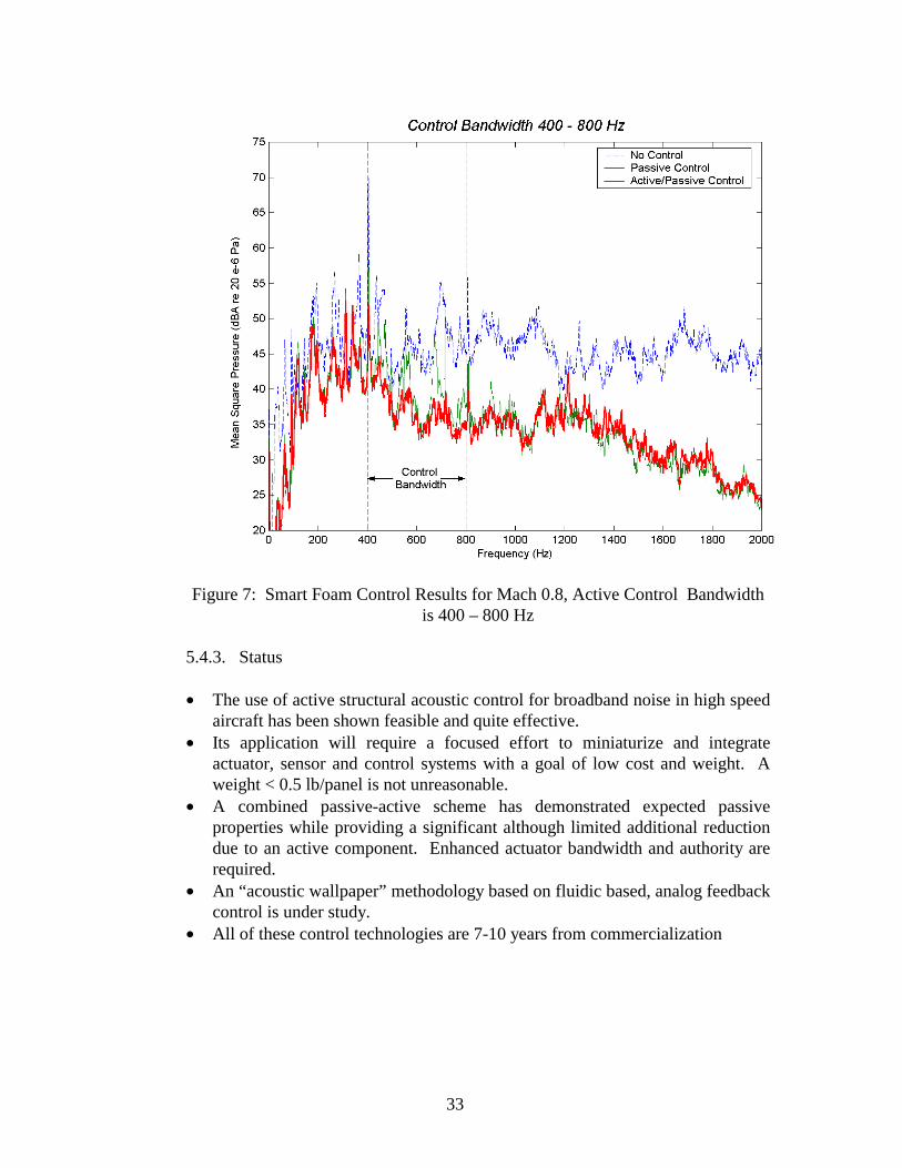
33
Figure 7: Smart Foam Control Results for Mach 0.8, Active Control Bandwidth
is 400 – 800 Hz
5.4.3. Status
• The use of active structural acoustic control for broadband noise in high speed aircraft has been shown feasible and quite effective.
• Its application will require a focused effort to miniaturize and integrate actuator, sensor and control systems with a goal of low cost and weight. A weight < 0.5 lb/panel is not unreasonable.
• A combined passive-active scheme has demonstrated expected passive properties while providing a significant although limited additional reduction due to an active component. Enhanced actuator bandwidth and authority are required.
• An “acoustic wallpaper” methodology based on fluidic based, analog feedback control is under study.
• All of these control technologies are 7-10 years from commercialization

34
5.5. HSCT Interior Noise Predictions
5.5.1. MD-80-Based Predictions As described in Section 4.5.1, estimates of HSCT interior noise levels were made several times throughout the program using MD-80 cabin noise levels measured in flight, with adjustments for the correct exterior excitation (supersonic turbulent boundary layer plus engine noise instead of subsonic boundary layer), and the correct fuselage sidewall transmission loss characteristics (composite structure instead of aluminum structure). These estimates changed periodically, as new data became available on the transmission loss of the composite skin-stringer and composite honeycomb sandwich fuselage sidewall constructions. The estimated HSCT interior noise levels were consistently higher than the interior noise level targets described in Section 3.1, especially in the aft portion of the aircraft where the contribution of the engine noise substantially increases the interior noise levels. To reduce these levels to the target levels, the noise reductions due to selected conventional, passive treatments (primarily the use of damping on the skin and trim panels and additional fiberglass insulation) were applied analytically, and the resulting weight penalties for these treatments were determined. The upper portion of Figure 8 shows the latest estimates of HSCT interior noise levels for Mach 2.4, 60,000 ft cruise conditions, for fuselage configurations where the entire structure is either all composite skin-stringer or all composite honeycomb sandwich construction. These estimates used the most recent TL data for the respective composite sidewall designs. The lower portion of the figure shows the distribution of treatment weight that would be required to reduce cabin levels to meet the target noise levels. The treatment weights of 8085 lb. for the honeycomb sandwich fuselage and 3570 lb. for the skin-stringer fuselage correspond to maximum takeoff weights of approximately 32,000 lb and 14,000 lbs, respectively; expressed as weight penalties these are 0.65 and 0.30 lb/ft2, respectively. It should be noted that noise reduction which may be realized through the use of the advanced passive and active noise control techniques discussed in the previous sections are not taken into account in these estimates.
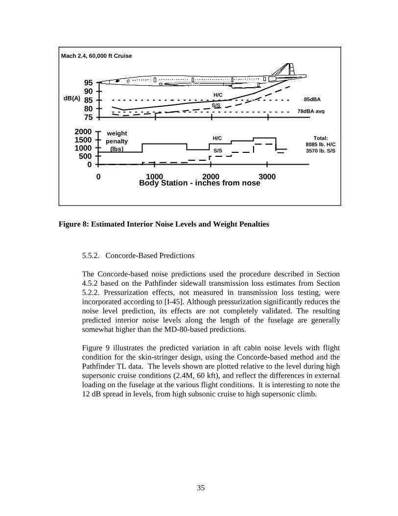
35
7580859095
dB(A)
78dBA avg
85dBA
0500
100015002000
0 1000 2000 3000Body Station - inches from nose
weightpenalty
(lbs)
Total:8085 lb. H/C3570 lb. S/S
H/C
S/S
H/C
S/S
Mach 2.4, 60,000 ft Cruise
Figure 8: Estimated Interior Noise Levels and Weight Penalties
5.5.2. Concorde-Based Predictions
The Concorde-based noise predictions used the procedure described in Section 4.5.2 based on the Pathfinder sidewall transmission loss estimates from Section 5.2.2. Pressurization effects, not measured in transmission loss testing, were incorporated according to [I-45]. Although pressurization significantly reduces the noise level prediction, its effects are not completely validated. The resulting predicted interior noise levels along the length of the fuselage are generally somewhat higher than the MD-80-based predictions. Figure 9 illustrates the predicted variation in aft cabin noise levels with flight condition for the skin-stringer design, using the Concorde-based method and the Pathfinder TL data. The levels shown are plotted relative to the level during high supersonic cruise conditions (2.4M, 60 kft), and reflect the differences in external loading on the fuselage at the various flight conditions. It is interesting to note the 12 dB spread in levels, from high subsonic cruise to high supersonic climb.
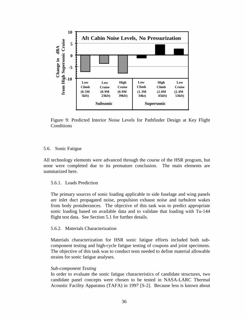
36
-10
-5
0
5
10
Cha
nge
in
dB
Afr
om H
igh
Supe
rson
ic C
ruis
e
Subsonic Supersonic
LowClimb
LowCruise
HighCruise
LowClimb
HighClimb
LowCruise
Aft Cabin Noise Levels, No Pressurization
(0.5M 5kft)
(0.9M 23kft)
(0.9M 39kft)
(1.3M 34kt)
(2.0M 45kft)
(2.4M 53kft)
Figure 9: Predicted Interior Noise Levels for Pathfinder Design at Key Flight Conditions
5.6. Sonic Fatigue
All technology elements were advanced through the course of the HSR program, but none were completed due to its premature conclusion. The main elements are summarized here.
5.6.1. Loads Prediction The primary sources of sonic loading applicable to side fuselage and wing panels are inlet duct propagated noise, propulsion exhaust noise and turbulent wakes from body protuberances. The objective of this task was to predict appropriate sonic loading based on available data and to validate that loading with Tu-144 flight test data. See Section 5.1 for further details. 5.6.2. Materials Characterization
Materials characterization for HSR sonic fatigue efforts included both sub-component testing and high-cycle fatigue testing of coupons and joint specimens. The objective of this task was to conduct tests needed to define material allowable strains for sonic fatigue analyses.
Sub-component Testing In order to evaluate the sonic fatigue characteristics of candidate structures, two candidate panel concepts were chosen to be tested in NASA-LARC Thermal Acoustic Facility Apparatus (TAFA) in 1997 [S-2]. Because less is known about

37
acoustic fatigue of honeycomb panels, both candidates tested were honeycomb core panels with face sheets. One was an ASTECH titanium core panel with titanium face sheets. The other was a titanium core panel with IM7-PETI5 face sheets. Testing of each panel was performed for one simulated lifetime of 15,000 hours at 158dB for the wing strake. During the tests, there were no signs of structural degradation while monitoring the frequency response of the panels. Periodic ultrasonic non-destructive inspections performed prior to, during, and after the test revealed no damage to the panels [S-1].
Sonic Fatigue Coupon Testing The primary step to determining the acoustic fatigue life of candidate structures is to calculate the damage caused by panel strain response. Sonic fatigue coupon tests were conducted on candidate materials that were to be used in the skin stringer structural concepts. Ti 6-2-2-2-2 and IM7/PETI-5 were the primary material candidates that had been previously tested by the HSR CAS and Metals ITD teams under the material development phase of the program. The purpose of these tests was to study the effect of static pre-load and temperature on fatigue life. The results of these tests were then to be used in the design and evaluation of candidate structures. Midway through the testing in 1997, metals were abandoned as candidates for the aircraft skin. A summary of coupon tests conducted is found in Table 1 [S-1].
Table 1: High Cycle Fatigue Test Summary
MATERIAL CONDITION TEST DATE COMMENTS
Metals
Ti 6AL-4V Annealed Sept. 95 Room temp., R=-1, Kt=1.0
Ti 6-2-2-2-2 SPF Disbond Oct. 95
Annealed, Aged, Pickled,
Sept. 94 - July 97
Room temp., 350oF, no preload, R = -1, R=-1/2,
R=0
SP 700 Annealed, Sim SPF & Aged
July 95, Nov. 95
IMI 550 Annealed, Sim SPF & Aged
June 95, Nov. 95
β−21s STA Sept. 95 Room temp., 350oF
Composites
IM7/K3B Includes HYBOR, Hybrid Nov. 95 Room temp., 350oF
IM7/PETI-5 Includes 25% Boron, 10%
Boron
Feb. 96, Apr. 96, Sept. 97
Room temp., 350oF

38
5.6.3. Sonic Fatigue Code Development The non-linear random structural response NASTRAN Direct Matrix Abstraction Programming (DMAP) code developed by NASA was chosen as the best base application for sonic fatigue analysis. This development proceeded through 1999 with the goal to employ it for sonic fatigue analysis of baseline HSCT structure when the process sufficiently matured. The methodology was recently improved [S-3, S-4] and the code rewritten to improve its accuracy over the earlier SEMELRR version [S-5]. Efforts to couple it to MSC/Fatigue for a multi-modal fatigue-life calculation are planned for FY 2000 under the NASA Airframe Systems Ultra-Lightweight Structures program. By the conclusion of the sonic fatigue effort, an interim analysis process was developed and used in lieu of the final analysis process using the non-linear DMAP and MSC/Fatigue as outlined above. Both processes are shown in flowchart form in Figure 10.
Interim Analysis Process Final Analysis Process
RMS Stress ContourPlots (usr_random)
Convert to StrainEXCEL
MSC NASTRANNon-linearFrequency
Response SolutionNASA -SEMELRR
DMAP
Strain lessthan limit
MSC NASTRANLinear FrequencyResponse Solution
Loading• Static/Thermal• Acoustic
Structural Design• Geometry• Material
x
yz
Fatigue Database• Material
0
400
800
1200
1600
2000
2400
2800
3200
1.00E+05 1.00E+06 1.00E+07 1.00E+08 1.00E+09
Cycles to Failure
RMSStrain(µin/in)
Note: O pen s ymbols are r un-outpoi nts
IM7/PET I-5
IM7/PET I-5 @ 350F
IM7/PET I-5 Joi nt
100
110
120
130
140
150
160
170
10 100 1000 10000Octave Band Frequency (Hz)
Spectrum(dB)
Octave Band SPL - 163.5 dB1 Hz Spectrum Level
MSC PATRAN
Life ContourPlot
Sonic FatigueResistant Design
No
Re-DesignStructure
AdequateLife
No
MSC FATIGUEmodule
Figure 10: Sonic Fatigue Analysis Interim and Final Processes
39
5.6.4. Response Reduction Techniques The objective of these analytic and experimental studies was to develop passive techniques / structural treatments to improve sonic fatigue resistance for critical structural components of the High Speed Civil Transport. Damping Treatments An analysis was performed to determine the extent of damping which can be obtained from the addition of damping layers in the fuselage skin laminate or the addition of damped, segmented stiffeners. Four different methods of damping the structure were investigated. These included: (1) adding constrained layer damping to the inside skin surface, (2) adding damped longitudinal stiffness in the center of the skin panels, (3) adding transverse damped stiffness to the skin panels, and (4) a configuration using damped cross stiffeners with augmented stringers. Details of this work and validation testing as part of the AEDC supersonic wind tunnel tests may be found in [S-1]. SMA Hybrid Composites A thermomechanical response prediction tool for composite structures with embedded shape memory alloy (SMA) actuators was developed early in the HSR program and was reported in Turner et al. [S-6]. That work was terminated under the HSR program in 1997, but was continued under the NASA Langley Aircraft Morphing Program. Efforts since that documented in the above citation include reformulation of the SMA hybrid composite constitutive model and resulting finite element thermomechanical analysis formulation, development of a SMA actuator characterization capability, and development of a SMA hybrid composite fabrication capability.
5.6.5. Sonic Fatigue Design Requirements Minimization of the thickness of skin panels and substructure has the potential for significant cumulative weight savings over an entire aircraft. The objective of this task was to develop guidelines for initial design of efficient fuselage structure tolerant of the severe exterior acoustic noise environment experienced by the HSCT. Sonic fatigue analyses were conducted on representative HSCT side fuselage skin panel/stringer/frame and honeycomb panel/frame sub-components to define structure capable of achieving the sonic fatigue goal. Two alternate structural systems for HSCT fuselage structure were considered. The first of these is a system of IM7/PETI-5 composite panels stiffened by a grid consisting of longitudinal frames and web stringers between those frames. The second of these systems is a PMC-TI honeycomb panel configuration stiffened only by longitudinal frames. Sonic fatigue design curves were developed for these configurations. These design requirements define minimum structural gage and,
40
therefore, minimum weight required for an airframe that shall withstand sonic loads throughout its service life. Preliminary sonic fatigue analysis was also performed on the HSCT wing design. This analysis was based on the HSCT design sonic loading due to inlet noise, interim design curves developed for PMC-TI honeycomb structure (applied previously to fuselage panels) and NASTRAN/PATRAN parametric linear response procedures. The objective was to provide guidance to the HSR Wing Design Team and to provide comments on the current design. The following conclusions are based on the sonic fatigue analyses: • The skin/stringer fuselage design requires little modification. Some design
detail to stabilize the edge of the stringer flanges would reduce the penalty in strain allowable for the high Kt at the edge of the stringer flange.
• Frame spacing in excess of 40-50 inches for the fuselage PMC honeycomb concept is not recommended due to high vibratory response associated with the large unsupported panels.
• Core thickness less than 0.5 inches should be avoided in the wing honeycomb design.
Further details of the design requirements effort may be found in [S-1].

41
6. Summary of Results
6.1. Interior Noise
Sources of Excitation • The TBL pressure fluctuation models were developed and verified using
measurements on supersonic airplanes. • Large amounts of TBL pressure fluctuation, structural vibration and cabin noise
data were collected from the Tu-144 flight test program. • Engine inlet and exhaust noise levels based on Tu-144 flight data are much more
severe than predictions based on tactical aircraft with supersonic capability, such as the F-15 and AV-8B [S-1].
Structural Acoustics Modeling • Modifications and additions were incorporated within the MDE code to make it
applicable to the HSCT fuselage, including development of composite and honeycomb elements and implementation of supersonic boundary layer excitation.
• Predictions of the structural response and/or noise transmission through HSCT-type composite panels were validated with TL data, supersonic wind tunnel test data, and (to a limited extent) Tu-144 flight test data.
• AutoSEA ties acoustic characteristics of a panel to its material and design properties, allowing design variations to be evaluated efficiently. It also allows effects (like pressurization) not available from conventional tests to be evaluated.
• AutoSEA captures the main characteristics of the fuselage panels and matches test data reasonably well. Caution is still advised in predicting absolute levels.
Passive Treatments • The size and shape of a honeycomb panel has more influence on its acoustic
performance than a panel with a skin/stringer construction. There are two reasons for this:
4) The honeycomb panel ring and coincidence frequencies are much closer in frequency than a skin/stringer panel.
5) The skin/stringer panel is broken into small elements by the stiffeners where as the smallest honeycomb panel element is much larger because it has very few stiffeners.
The consequence for structural-acoustic testing is that honeycomb panels should be large and curved so that the important acoustic features are captured in the test.
• The areas where sidewall passive controls may be improved relative to current subsonic design are:
1) Trim panel mounting with few attachments between trim and primary structure will have better transmission loss above 1000 Hz.
2) The most efficient use of mass is to increase the trim panel weight and stiffness so that the double wall performance is improved.
3) More noise reduction may be possible if fiberglass insulation is optimized.
42
• The residual thermal fabrication stresses in a composite panel can alter its modal response. These stresses may be required in an analytical model to achieve good test-to-model correlation.
• Flight and pressurization loads can change structural response significantly in both frequency and shape. As a result, add-on damping performance may be effected.
• Loaded structural stiffening pushes coincidence frequencies so low as to make all panel modes good radiators of sound energy during cruise. Add-on structural damping is an effective means of suppressing the radiated noise produced at coincidence by the resonant panel modes.
• The standoff constrained layer damping design is more weight efficient when applied to skin/stringer panels than honeycomb panels. The factor is around 3 times more efficient for the skin/stringer on a delta dB per pound of added surface weight.
Active Controls • ASAC has been shown to be a viable technique for broadband noise reduction but
will require extensive integration for cost and weight reduction. • Smart foam is an emerging technology that will require additional development in
actuator authority and bandwidth to be effective. • Fluidic trim has the potential to provide substantial noise reduction, but is still in
an embryonic stage of development. • A range of innovative active control technologies have been proposed that will
require extensive additional development and may not be expected to be deployed until well into the next decade.
HSCT Interior Noise Predictions • The latest predictions of HSCT interior levels show that these levels will exceed
the design goals by up to 15 dBA using subsonic aircraft insulation and trim, depending on location within the aircraft, type of sidewall configuration, and flight condition. To meet the HSCT cabin noise goals, the passive and active noise control techniques investigated to date will have to be further developed and brought to maturity and their application optimized into a total treatment package.
6.2. Sonic Fatigue
• IM7/PETI-5 Material Characterization: This material is extremely resistant to
high cycle fatigue damage with allowable strains exceeding those for titanium. It has little or no reduction in properties at 350ºF. It should be tested at temperatures up to 500ºF to determine its true limits.
• Skin-Stringer Fuselage Concept: This concept, as designed, is very close to meeting requirements developed for sonic fatigue resistant structure. Sonic fatigue analyses were conducted on representative HSCT side fuselage sub-components to define structure capable of meeting the sonic fatigue goal. Initial design curves, developed by NASTRAN linear response parametric analyses,

43
provide required thickness values for skin panels, stringer webs and stringer flange areas. These criteria were applied to the fuselage pathfinder designs. It was assumed that high acoustic impingement exists on the side of fuselage Section 43 due to a wake from the canard and on the sides and bottom of fuselage Section 46 as a result of engine exhaust noise. Minor changes were recommended in the areas below the window belt and passenger floor [S-1]. This design concept could be improved significantly if the terminations in the stringer flanges were tapered. This would increase the endurance limit significantly and possibly remove most of the required structural gage increases recommended for sonic fatigue considerations.
• PMC-TI Honeycomb Concept: High cycle fatigue resistance of PMC-TI honeycomb structure is governed by its limited shear capability in the bond between the honeycomb and face sheet. This failure mechanism was identified by testing of honeycomb strip beams and verified by NASTRAN linear response vibration analyses of the strip beams and sonic fatigue analyses of panels. Design curves were developed from these analytic results and applied to representative HSCT panels. To accommodate this limited shear capability of the bond, core thickness less than 0.5 inch and panel dimensions greater than 50 inches are to be avoided.
• Tu-144 Flight Data: Sonic fatigue design requirements were based on the lower tactical aircraft predictions because it is expected that an aircraft with the noise characteristics of the Tu-144 would not be economically viable.
• Addition of Damping to Structure: Because of the very high durability of IM7/PETI-5, the addition of viscous damping layers to reduce sonic fatigue is not weight effective for a skin-stringer fuselage. Increasing material gages or adding substructure, where required, seems to be more efficient. Damping techniques may be required, however, for other aircraft components, such as empennage or control surfaces, which were not analyzed in the present program.

44
7. Lessons Learned and Recommendations for the Future
7.1. Programmatic Several points related to program management and function, both positive and negative, are worth noting. On the plus side: • The Structural Acoustics ITD Team functioned very well under the policy of
management by consensus. We were able to draw upon the technical strengths of each organization and divide work along these lines rather than equally dividing work by dollar value or some other non-technical rational.
• A stable team membership with appropriate representation of technical areas enabled multi-year plans to be formulated and followed. A good choice of supporting subcontractors (Lockheed-Martin, Purdue University, VPI, Stanford Research Institute, etc.) helped enable these plans to be fulfilled.
• Multi-year PCD plans, though painful to develop, helped keep the program on track and afforded a sufficient level of flexibility for change as necessary.
• The program was aimed at minimizing risk, e.g. a planned work cycle of testing, model verification, and prediction update in an iterative fashion.
• Annual reviews were beneficial, although the amount of technical review was diminished when other team reviews were held concurrently. Separately held semi-annual reviews tended to be more technically productive. Open communications facilitated resolution of technical and programmatic issues in a timely fashion.
• The team was able gain support from the TMT only after the weight impact associated with interior noise and sonic fatigue was recognized and appreciated relative to other technology areas. Early in the program, this was not the case and the budget suffered from continual cuts.
On the minus side: • Budgets were not assured and stable over a long period of time. Annual re-
planning efforts, which could have been used to productively change plans for technical reasons, turned largely into self-preservation exercises. This had the effect of diverting already precious resources to non-productive tasks. Further, providing detailed budget information had the negative effect of making it easy to take budget away.
• Work on high risk, high-payoff technical work was difficult to defend and this was reflected in the program plan.
• It was difficult to get a handle on costs associated during wind tunnel and TL facility testing during the planning process. This had the undesirable effect of cost overruns and the necessity to postpone or cut other work in order to stay within budget.
• Because the Structural Acoustics effort was to effectively end in FY 2000, an aggressive PCD2 period was planned for technology development in order to

45
leave the PCD3 period for integration and optimization. In hindsight, a more liberal technology development schedule would have allowed the plan to be more effectively executed.
7.2. Technical
7.2.1. Interior Noise
The HRS Interior Noise program was successful in advancing the interior noise control technology. However, since the HSR program was terminated prematurely, a number of technical advances were not brought to fruition. The following lessons learned lead to specific recommend actions for continuing the interior noise reduction technology effort: • Accurate TBL predictions are necessary for accurate interior noise level
predictions. The accuracy of the TBL model can be improved if evaluations of the forward and backward facing step data collected during the 1998-1999 Tu144 flight-test program are carried out. Also, measurements need to be made of the effects of pressure gradient on the TBL excitation. All of these results should be integrated into a new exterior prediction procedure. This new prediction process should be extended to include cross spectrum estimation.
• Controlling noise at the source is the most effective method of achieving substantial noise control. Therefore, as a long-term effort, TBL modification and control (e.g., BL suction, cooling, tripping, etc.) should be investigated to reduce the source of excitation and, hence, reduce supersonic airplane interior noise.
• The JN8NR code for near-field jet noise prediction requires substantial computational resources and is somewhat time consuming to run as a result of several numerically intense algorithms. It is recommended that some empirical formulas that would provide quick prediction capabilities be distilled from this analytically oriented code.
• The effects of pressurization are important and may have significantly different effects on the composite panels. All of the TL testing in the current program was carried out without pressurization. Therefore, it is recommended that future TL testing include the pressurization. The TL test data thus acquired can then be used with a higher level of confidence in verifying the prediction models and for making the decisions on fuselage configuration selections.
• Fiberglass analytical modeling has shown that there is a potential for greater noise control, 3 to 5 dB average improvement in Speech Interference Level, with no weight penalty if fiberglass insulation can be successfully re-engineered. It’s recommended that samples be fabricated and tested.
• Two key points were learned about acoustic testing of composite structural panels: 1) the size and shape of honeycomb panels has a strong influence on the test result, and 2) panels need to be designed to the same loads to get the best acoustic comparison between panels. The size and shape has the greater

46
influence on honeycomb panel results where the ring frequency and coincidence frequencies are closer than the skin/stringer design. To capture the important acoustic features, and to get an accurate picture of the relative performance between skin/stringer and honeycomb panels, these panel features are recommended: 1) test panels need to be designed to the same structural loads, 2) should be fabricated with the best available materials, 3) minimum dimensions of around 5 by 3 feet (3 feet on the curvature), and 4) have curvature like that of the airplane.
• Although the AEDC wind-tunnel tests provided structural-acoustic data that was not previously available, several test changes would have made the resultant database even more useful. The first recommendation is that a future wind-tunnel test should be done with larger test panels. This is especially true for the honeycomb panel. The second recommendation is that the acoustic measurement area, the volume behind the test panel, must have a lower noise level environment than the 1998 AEDC tests. A lower noise level environment is necessary for passive controls testing of trim and insulation. An acoustic enclosure is the recommended method to achieve the lowest ambient levels.
• Active noise control techniques are effective in reducing airplane interior noise levels caused by turbulent boundary layer excitation, as demonstrated by AEDC wind-tunnel tests. Additional testing should be performed to develop techniques for optimization and practical implementation of active-noise control hardware for use on an airplane as a noise-control treatment. This development work should include a wide range of investigations from ways of determining the numbers and locations of the control hardware (piezoelectric patches, smart foam, etc.) to what kind of hardware will be suitable for in-service application on the airplane.
• There are indications that the effectiveness of individual noise control treatments diminishes when combined with other individual treatments. It is recommended that testing and modeling of passive and active control in combinations be carried out for the purpose of developing an understanding of why and how this happens, how to predict the combined behavior, and eventually develop techniques that overcome this effect.
• The HSCT damping design must work effectively at the low temperature subsonic cruise segment and the high temperature supersonic cruise segment. The simple approach of stacking the low- and high-temperature dampers results in an unacceptable weight penalty. A better damper design is necessary so that the added weight is reasonable. Therefore, it is recommended that the development of passive treatments for the primary structure continue. Three areas should be focused on: 1) complete a two temperature damping design for both the honeycomb and skin/stringer fuselage; 2) determine how fuselage loading affects the damping design - placement of damping and the change in damping level with load; and 3) investigate if the viscoelastic damping can be included in the composite lay up process.

47
• One method of finding the best acoustic design is to develop a tool that can take all the important acoustic design parameters and find optimum values. Although there are optimizer tools available, there was nothing that could do the optimizing for HSCT sidewall acoustic design. Therefore, an AutoSEA2 sidewall TL optimization tool was developed. Preliminary results have shown that the tool will predict a noise-control improvement similar to the honeycomb double core thickness test results of August 1999. The tool appears promising and, therefore, it is recommended that this tool, or something like it, be developed further because it has the potential to optimize (minimum weight with maximum noise control) the noise control treatment throughout the entire fuselage.
7.2.2. Sonic Fatigue The HSR Sonic Fatigue program provided considerable useful information, which if extended, would be even more valuable. The following lessons learned lead to specific recommendations for continuing effort: • Sonic-fatigue design requirements were based on HSCT predictions made
from tactical aircraft data. However, limited analysis of the Tu-144 flight data has indicated that the HSCT sonic loading is higher than that predicted from the tactical aircraft data. To improve the accuracy of HSCT predictions it is recommended that further analysis of the Tu-144 flight data be performed. This analysis would specifically address the distribution of sonic loads on all high acoustic zones of the airframe, i.e., to develop a sonic load map of the airframe. High acoustic load zones include the engine nacelles, trailing edge control surface and empennage. These data can then be scaled based on HSCT expected engine flow rates, areas and temperatures to yield more accurate sonic load predictions.
• IM7/PETI-5 is extremely resistant to high-cycle fatigue damage with allowable strains exceeding those for titanium. It has little or no reduction in properties at 350ºF.
• Current linear analysis and the resulting uncertainties in results lead to conservative, relatively heavy designs. Completing the development of the NASTRAN DMAP solution for non-linear dynamic response and the life calculation (MSC Fatigue) fatigue module is recommended so that more accurate sonic fatigue analyses can be performed.
• Sonic-fatigue resistant structure can best be achieved when sonic-fatigue analysis is an integral part of the airplane detailed design. Therefore, it is strongly recommended that any future structural design effort include sonic-fatigue analysis as an integral part of the design. It is very important to evaluate structural design details, such as close-outs at the edges of honeycomb panels which could be prone to adhesive shear failures in areas of high dynamic response of large panels, which would cause significant problems if not addressed.
48
8. Bibliography
8.1. Interior Noise
1. Boeing Report CRAD-9408-TR-6045, "1999 Interior Noise Final Report," September 30, 1999
2. Denke, P.H., "Matrix Difference Equation Analysis of Coupled Structural-
Acoustic Models for Aircraft Fuselage Vibration and Interior Noise Reduction," Proc. DGLR/AIAA 14 Aeroacoustics Conference, Aachen, Germany, pp 396-402, May, 1992
3. Denke, P.H., "Vibrating Spatially Periodic Structures with Simply Supported and
Guided Ends," SAE Transactions, 88, 1979.
4. Barisciano, L. P. “Broadband Transmission Loss due to Reverberant Excitation,” George Washington University Masters Thesis, August 1998, NASA/CR-1999-209687, November 1999.
5. AutoSEA User Guide (Version 1.5), Vibro-Acoustic Sciences Ltd, 1996.
6. Transmission Loss of Composite Panels Evaluated with SEA, Contract NAS1-
20220, Task 49 (Structural Acoustics), H. W. Poling, April 1999.
7. Phil Shorter, "Acoustic Optimization of Aircraft Fuselage Panels Using AutoSEA2," Vibro-Acoustic Sciences technical report, September 1999.
8. “The Prediction of the Pressure Fluctuation Field Characteristics of the Turbulent
Boundary Layer” Boeing Document No. BTRC101F-5/95 by B. M. Efimtsov et al. (May 1995)
9. “Cabin Noise and Turbulent Boundary Layer Pressure Fluctuations on a British
Airways Concorde Aircraft – Test Report” Boeing Document No. T6-6970 by K. T. Lohman (Jan. 1994)
10. “An In-flight Supersonic Turbulent Boundary Layer Surface Pressure Fluctuation
Model” Boeing Document No. D6-81571 by P. W. Goodwin (Nov. 1994)
11. “Flight Research Using Modified Tu-144 Aircraft – Final Report” Boeing NASA Contract NAS1-20220, Experiment 2.1 Structures/Cabin Noise by Robert G. Rackl and Stephen A Rizzi (May 1998)
12. “Results of acoustic loads measurements on Tu-144LL airplane structure”
Tupolev ANTK report on Experiment 2.1, by V. P. Shunaev et al (March 1998)

49
13. “Modeling of Turbulent Boundary Layer Surface Pressure Fluctuation Auto and
Cross Spectra – Verification and Adjustments Based on Tu-144LL Data” Boeing NASA Contract NAS1-20220, Task Assignment Number 27 Report by Robert Rackl and Adam Weston (Nov. 1998)
14. “Tu-144 Follow-on Program – Final Report”, NASA Contract NAS1-20220,
Experiment 2.1A Structure/Cabin Noise, Robert G. Rackl and Stephen A. Rizzi, June 1999
15. Frendi, A., “On the Coupling Between a Supersonic Turbulent Boundary Layer
and a Flexible Structure,” NASA Contractor Report 201631, October 1996.
16. Frendi, A., “Effect of Pressure Gradients on Plate Response and Radiation in a Supersonic Turbulent Boundary Layer,” NASA Contractor Report 201691, March 1997.
17. Maestrello, L., “Radiation from and Panel Response to a Supersonic Turbulent
Boundary Layer,” J. Sound and Vibrations, vol. 10, no. 2, pp. 261-295.
18. MDC Report CRAD-9408-TR-1405R2, "Final Report for Task 17, Subtask 2," January 1996.
19. MDC Report CRAD-9306-TR-0057, "Preliminary Interior Noise and Sonic
Fatigue Technology Studies for HSCT; Volume 2. Boundary Layer Structural Interaction Modeling," October 1994.
20. Corcos, G.M., "The Resolution of Pressure in Turbulence," J. Acoust. Soc. Am.,
35, 192-199, 1963.
21. Boeing Report CRAD-9408-TR-3726, "1997 Interior Noise Final Report," October 1997.
22. “Facilities Requirements for HSR II Interior Noise Work”, NAS1-20013 (D6-
81572), G. R. MacGregor, 12/9/1994
23. Boeing Report CRAD-9408-TR-2665, "1996 Interior Noise Final Report," December 1996.
24. Boeing Report CRAD-9408-TR-5062R, "1998 Interior Noise Final Report,"
October 1998.
25. Boeing Report CRAD-9408-TR-5515, "Interior Noise Prediction Model Assessments," April 1999.

50
26. “1997 Interior Noise Report”, Contract NAS1-20220, Task Assignment Number 27, M. L. Andre, November 1998
27. “Passive and Active Control Technology Development”, Contract NAS1-20220,
M. L. Andre, September 30, 1999
28. “HSR Interior Noise Technology Development Activities at Boeing During 1995”, Final Informal Report, Contract NAS1-20220, Task Assignment Number 17, R. G. Rackl, February 15, 1996
29. “Passive and Active Noise Control Techniques for Interior Noise”, Contract
NAS1-20220, Task Assignment Number 27, Revision A: February 1, 1999
30. “Optimization of Fuselage Lining Materials”, Dr. J. Stuart Bolton, Purdue University, HL 99-13 Report #0782-1, September 1999
31. “HSR Interior Noise Technology Development Activities at Boeing During
1996”, Final Informal Report, Contract NAS1-20220, Task Assignment Number 27, M. L. Andre, R. G. Rackl, J. R. Johnescu, January 6, 1997
32. Structural Acoustics ITD Team Mid-Term Review, Structural Acoustics ITD
Team, 12/9/1998
33. Final Technical Report, NAS1-20220/ZA0418, Dr. J. Soovere′, Lockheed Martin Aeronautical Systems, November 30, 1997
34. Final Technical Report, NAS1-20220/ZA0424, Dr. J. Soovere′ and O. Berry, ,
Lockheed Martin Aeronautical Systems, October 31, 1998
35. Final Technical Report, Subtask 4 - Structural Acoustics, Task 49 - Fuselage Structure, NASA High Speed Research Program Contract NAS1-20220, Lockheed Martin Aeronautical Systems, Prepared for the Boeing Company Under Contract No. ZA0429, O. T. Berry and J. Soovere, August 27, 1999
36. MDC Report CRAD-9310-TR-2493, "Broadband Active Control of Noise in a
DC-9 Fuselage Test Section," D.K. Peterson (SRI International), October 1996.
37. D. E. Cox, G. P. Gibbs, R. L. Clark, and J. S. Vipperman, “Experimental Robust Control of Structural Acoustic Radiation,” Journal of Vibration and Acoustics-Transactions of the ASME, Vol. 121 (4), October 1999, p. 433-439.
38. Curtis, A.R.D. and Remington, P.J., “Model for the Control of Sound Radiation
from an Aircraft Panel Excited by a Turbulent Boundary Layer Using Impedance Control,” AIAA paper no. 99-1936, presented at the AIAA Aeroacoustics Conference, Seattle WA 1999.

51
39. Juang, J.-N., and Eure, K.W., "Predictive Feedback and Feedforward Control for
Systems with Unknown Disturbances," NASA/TM-1998-208744, December 1998.
40. G. P. Gibbs, R. L. Clark, D. E. Cox, and J. S. Vipperman, “Radiation Modal
Expansion: Application to Active Structural Acoustic Control,” Journal of the Acoustical Society of America, Vol. 107 (1), January 2000, p. 332-339.
41. J.R. Griffin, M.E. Johnson and C.R. Fuller,” Active Control of Transmission of
Turbulent Boundary Layer Noise Using Smart Foam Elements.” Journal of the Acoustical Society of America, Vol 104(3), p.1851, 1998.
42. M.E. Johnson, J.R. Griffin and C.R. Fuller, “Experiments on the Feedforward
Control of Turbulent Boundary Layer Noise,” Active 99, Ft. Lauderdale, FL December 2-4, 1999.
43. “Fluidic Smart-Material Acoustical Concept”, Anders O. Andersson, Proceedings
from Institute of Noise Control Engineering Noise-Con 96, Seattle Washington, 9/29/96 – 10/2/96, Volume I, page 417
44. G. P. Gibbs, K. W. Eure, and J. W. Lloyd, “Active Control of Turbulent Boundary
Layer Induced Radiation from Aircraft Style Panels,” to be submitted to the Journal of the Acoustical Society of America, 1999.
45. "Pressurization of the 'Pathfinder' HSCT Sidewall," Presentation by H. W. Poling,
March 1999.
8.2. Sonic Fatigue 1. Boeing Report CRAD-9408-TR-5559, Sonic Fatigue Final Report, Paul Heaton
and Theodor Beier, April 30, 1999. 2. Rizzi, S.A. and Turner, T.L., “Enhanced Capabilities of the NASA Langley
Thermal Acoustic Fatigue Apparatus,” Proceedings of the Sixth International Conference on Recent Advances in Structural Dynamics, Southampton, England, July 14-17, 1997, Volume 2, pp.919-933.
3. Muravyov, A.A., Turner, T.L., Robinson, J.H. and Rizzi, S.A., “A New Stochastic
Equivalent Linearization Implementation For Prediction of Geometrically Nonlinear Vibrations”, AIAA 99-1376, Proceedings of the 40th Structures, Structural Dynamics and Materials Conference, St. Louis, MO, April, 1999.
4. Muravyov, A.A., “Determination of Nonlinear Stiffness Coefficients for Finite

52
Element Models with Application to the Random Vibration Problem,” In MSC Worldwide Aerospace Conference Proceedings, Long Beach, MacNeal-Schwendler Corp., 1999, Vol. 2.
5. Robinson, J.H., Chiang, C.K., and Rizzi, S.A., “Nonlinear Random Response
Prediction Using MSC/NASTRAN”, NASA TM 109029, October 1993. 6. Turner, T.L., Zhong, Z.W., and Mei, C., “Finite Element Analysis of the Random
Response Suppression of Composite Panels at Elevated Temperatures using Shape Memory Alloy Fibers,” AIAA-94-1324-CP, Proc. of 35th Structures, Structural Dynamics and Materials Conf., Hilton Head, SC, pp. 136-146, April 18-21, 1994.

REPORT DOCUMENTATION PAGE Form ApprovedOMB No. 0704-0188
2. REPORT TYPE
Technical Memorandum 4. TITLE AND SUBTITLE
High Speed Research Program Structural Acoustics Multi-Year Summary Report
5a. CONTRACT NUMBER
6. AUTHOR(S)
Beier, Theodor H.; Bhat, Waman V.; Rizzi, Stephen A.; Silcox, Richard J.; and Simpson, Myles A.
7. PERFORMING ORGANIZATION NAME(S) AND ADDRESS(ES)
NASA Langley Research CenterHampton, VA 23681-2199
9. SPONSORING/MONITORING AGENCY NAME(S) AND ADDRESS(ES)
National Aeronautics and Space AdministrationWashington, DC 20546-0001
8. PERFORMING ORGANIZATION REPORT NUMBER
L-19087
10. SPONSOR/MONITOR'S ACRONYM(S)
NASA
13. SUPPLEMENTARY NOTESBeier, Bhat, and Simpson: The Boeing Company; Rizzi and Silcox: Langley Research Center.An electronic version can be found at http://ntrs.nasa.gov
12. DISTRIBUTION/AVAILABILITY STATEMENTUnclassified - UnlimitedSubject Category 71Availability: NASA CASI (301) 621-0390
19a. NAME OF RESPONSIBLE PERSON
STI Help Desk (email: [email protected])
14. ABSTRACT
This report summarizes the work conducted by the Structural Acoustics Integrated Technology Development (ITD) Team under NASA's High Speed Research (HSR) Phase II program from 1993 to 1999. It is intended to serve as a reference for future researchers by documenting the results of the interior noise and sonic fatigue technology development activities conducted during this period. For interior noise, these activities included excitation modeling, structural acoustic response modeling, development of passive treatments and active controls, and prediction of interior noise. For sonic fatigue, these activities included loads prediction, materials characterization, sonic fatigue code development, development of response reduction techniques, and generation of sonic fatigue design requirements. Also included are lessons learned and recommendations for future work.
15. SUBJECT TERMS
High Speed Research Program; Interior noise; Sonic fatigue; Structural acoustics
18. NUMBER OF PAGES
61
19b. TELEPHONE NUMBER (Include area code)
(301) 621-0390
a. REPORT
U
c. THIS PAGE
U
b. ABSTRACT
U
17. LIMITATION OF ABSTRACT
UU
Prescribed by ANSI Std. Z39.18Standard Form 298 (Rev. 8-98)
3. DATES COVERED (From - To)
5b. GRANT NUMBER
5c. PROGRAM ELEMENT NUMBER
5d. PROJECT NUMBER
5e. TASK NUMBER
5f. WORK UNIT NUMBER
537-06-37-20
11. SPONSOR/MONITOR'S REPORT NUMBER(S)
NASA/TM-2005-213536
16. SECURITY CLASSIFICATION OF:
The public reporting burden for this collection of information is estimated to average 1 hour per response, including the time for reviewing instructions, searching existing data sources, gathering and maintaining the data needed, and completing and reviewing the collection of information. Send comments regarding this burden estimate or any other aspect of this collection of information, including suggestions for reducing this burden, to Department of Defense, Washington Headquarters Services, Directorate for Information Operations and Reports (0704-0188), 1215 Jefferson Davis Highway, Suite 1204, Arlington, VA 22202-4302. Respondents should be aware that notwithstanding any other provision of law, no person shall be subject to any penalty for failing to comply with a collection of information if it does not display a currently valid OMB control number.PLEASE DO NOT RETURN YOUR FORM TO THE ABOVE ADDRESS.
1. REPORT DATE (DD-MM-YYYY)
03 - 200501-