Embed Size (px)
Citation preview
High Inlet Temperature Combustor for Direct Fired Supercritical Oxy-
Combustion
Aaron McClung, Ph.D.
Jacob Delimont, Ph.D.
Shane Coogan
Southwest Research Institute
Lalit Chordia, Ph.D.
Marc Portnoff
Thar Energy L.L.C.
11/3/20152015 University Turbine Systems Research
Workshop1
Work supported by US DOE under DE-FE002401
2015 University Turbine Systems Research WorkshopNovember 3, 2015

Outline
• Project Overview
– Project Objectives
– sCO2 Background
– Technical Challenges
• Selected Progress Update
– Cycle Evaluation
– Kinetic Models
– Supercritical Oxy-Combustor Design
11/3/20152015 University Turbine Systems Research
Workshop2

PROJECT OVERVIEW
11/3/20152015 University Turbine Systems Research
Workshop3

Project Objectives
• Optimize the supercritical CO2 power cycle for direct fired oxy-combustion
– Target plant conversion efficiency is 52% (LHV)
• Technology gap assessment for direct fired plant configurations
• Develop a high inlet temperature oxy-combustor suitable for the optimized cycle
– Target fuels are Natural Gas and Syngas
11/3/20152015 University Turbine Systems Research
Workshop4

What is a sCO2 cycle?
• Closed Brayton Cycle– Working fluid is CO2
• Cycle Type– Vapor phase– Transcritical– Supercritical
• Supercritical CO2 has:– High fluid density– High heat capacity– Low viscosity
11/3/20152015 University Turbine Systems Research
Workshop5
HEATSOURCE
PRECOOLER
RECUPERATOR
EXPANDERCOMPRESSOR
P5 P6
P1
P2
P4
COOLING OUTCOOLING IN
P3
Recuperated ClosedBrayton Power Cycle

Why sCO2 Power Cycles?
• Offer +3 to +5 percentage
points over supercritical
steam for indirect coal fired
applications
• High fluid densities lead to
compact turbomachinery
• Efficient cycles require
significant recuperation
• Compatible with dry cooling
techniques
11/3/20152015 University Turbine Systems Research
Workshop6
Third Generation 300 MWe S-CO2 Layout from Gibba, Hejzlar, and Driscoll, MIT-GFR-037, 2006
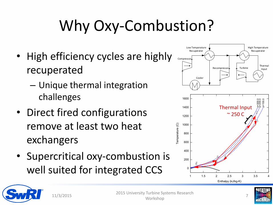
Why Oxy-Combustion?
• High efficiency cycles are highly recuperated
– Unique thermal integration challenges
• Direct fired configurations remove at least two heat exchangers
• Supercritical oxy-combustion is well suited for integrated CCS
11/3/20152015 University Turbine Systems Research
Workshop7
Thermal Input ~ 250 C
ThermalInput
Cooler
Low TemperatureRecuperater
High TemperatureRecuperater
Turbine
Compressor
Recompressor
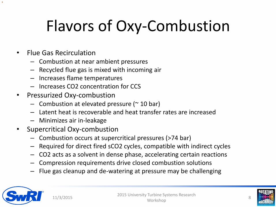
Flavors of Oxy-Combustion
• Flue Gas Recirculation– Combustion at near ambient pressures– Recycled flue gas is mixed with incoming air– Increases flame temperatures– Increases CO2 concentration for CCS
• Pressurized Oxy-combustion– Combustion at elevated pressure (~ 10 bar) – Latent heat is recoverable and heat transfer rates are increased– Minimizes air in-leakage
• Supercritical Oxy-combustion– Combustion occurs at supercritical pressures (>74 bar)– Required for direct fired sCO2 cycles, compatible with indirect cycles– CO2 acts as a solvent in dense phase, accelerating certain reactions– Compression requirements drive closed combustion solutions– Flue gas cleanup and de-watering at pressure may be challenging
11/3/20152015 University Turbine Systems Research
Workshop8

Progression
• System Design and Thermodynamic Analysis– Evaluate cycles to determine combustor design
parameters
• System level Technology Gap Assessment• Kinetics Models
– Evaluate kinetic models to determine applicability– Initial kinetic evaluation at combustor inlet conditions
• Combustor Concept– Material constraints at 1000 C 200 bar inlet, 1200 C
200 bar outlet conditions
• Combustor demonstration
11/3/20152015 University Turbine Systems Research
Workshop9

SYSTEM ENGINEERING DESIGN AND THERMODYNAMIC ANALYSIS
11/3/20152015 University Turbine Systems Research
Workshop10
DESIGN-SPEC
COMPMAT C
DESIGN-SPEC
FUELFLOW
DESIGN-SPEC
FUELPRES
DESIGN-SPEC
O2PRES
DESIGN-SPEC
PINLET
DESIGN-SPEC
T INLET
DESIGN-SPEC
T MIXBAL
CALCULATOR
COOLT OWR
CALCULATOREFFICIEN
CALCULATORO2CALC
PIPELCMP
PIPLNCO2
H2OSEPER FUELCOM
W
MIXER
FUELWORK
O2PUMP
COMBUST
W
MIXER
WMIXER
COOLER
FMIX
REJ ECT HX
FSPLIT
HXLOWHXHIGH
MAINCOMP
RECOMP
EXPANDER
CO2
S15
WPIPELIN
T AKEOFF
H20
S21
S3
CH4IN
CH4PRE
FUELCW
ASUPOWW
O2PWORK
WFUELSYS
O2IN
O2PRE
INLET
S14
WMAINCOM
WRECOMP
WT URBINE
WCOOLW
WNETW
S7
S10
QRECOMPC
Q
S9
S11
MAIN
S6
QREJECT
Q
RECOMPRE
S2
S8
S1
OUT LET
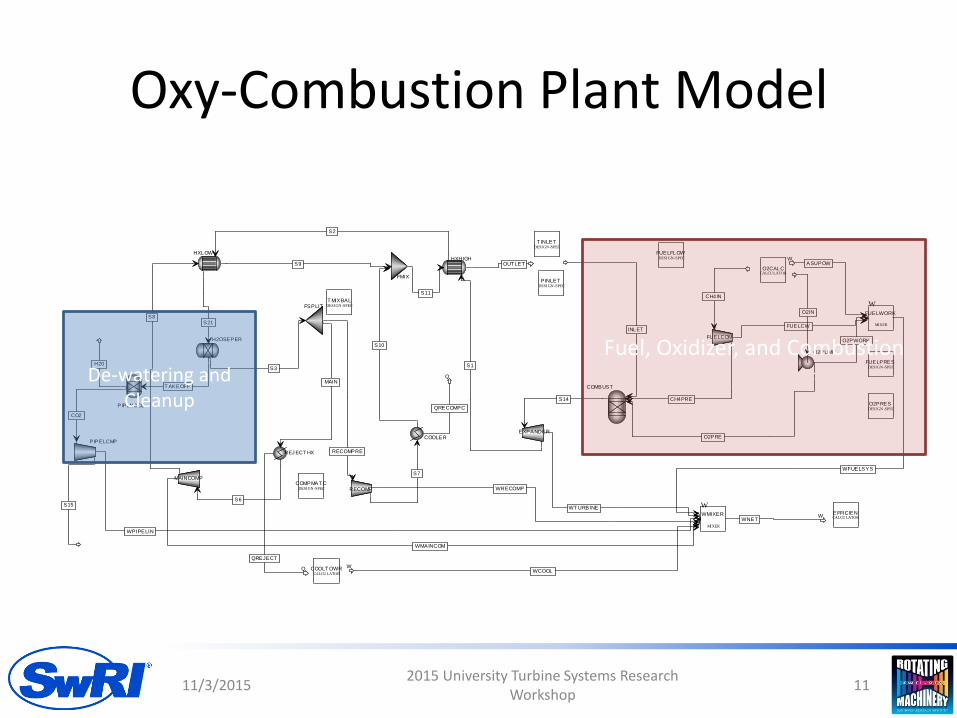
De-watering and Cleanup
Fuel, Oxidizer, and Combustion
Oxy-Combustion Plant Model
11/3/20152015 University Turbine Systems Research
Workshop11

Direct Fired Supercritical Oxy-Combustion
• Plant evaluation factors power cycle layout, environmental conditions, component performance, and secondary systems
• Plant optimization focused on thermal efficiency
– Target 52% plant efficiency to compete with NGCC
– Drives 64% power cycle thermal efficiency
– Turbine inlet near 1200°C
11/3/20152015 University Turbine Systems Research
Workshop12

10
20
30
40
50
60
70
300 400 500 600 700 800 900 1000 1100 1200
The
rmal
Eff
icie
ncy
Temperature (C)
sCO2
He
SupercrticialSteam
SuperheatedSteam
Idealized sCO2Recompression
75% of Carnot
WHR
Nuclear
Fossil
Representative Cycle Efficiencies
sCO2, He, Supercritical Steam, and Superheated Steam are from Driscol MIT-GFR-045,
2008
11/3/20152015 University Turbine Systems Research
Workshop 13

Partial Condensation and Recompression Cycles
ThermalInput
Cooler
Low TemperatureRecuperater
High TemperatureRecuperater
Turbine
Compressor
Recompressor
ThermalInput
11/3/20152015 University Turbine Systems Research
Workshop14
ThermalInput
Cooler
Recuperater
Turbine
Compressor
Pump
ThermalInput

Cycle ComparisonSingle
Recuperator Condensation
Single Recuperator
Condensation
Recompression Recompression
Net fuel to bus bar plantefficiency
54.03% 51.60% 56.73% 53.44%
Total Recouperation (kW) 989.91 1078.16 1163.44 1205.34HE Duty per Net PowerRatio (kW/kW)
2.48 3.21 4.34 6.55
Power per Mass Flow Ratio(kJ/kg)
399.06 335.38 268.08 183.92
Combustor Inlet Temp. (°C) 755.18 808.60 918.16 994.37Combustor Inlet Pres. (bar) 300.00 200.00 300.00 200.00** Cycles evaluated at 1200°C Turbine Inlet Temperature and unit 1 kg/s mass flow
11/3/20152015 University Turbine Systems Research
Workshop15

Cycle Analysis Results
• Recompression cycle has highest efficiency by 1.8% at 200 bar, 2.7% at 300 bar
• Condensation cycle is superior in all other metrics
– Reduced recuperation (~ 50%)
– Lower combustor inlet temperature
– Higher power density (power output / flow rate)
• Both cycle configurations are compatible with an auto-ignition style combustor for 1200 C Turbine inlet temperatures.
11/3/20152015 University Turbine Systems Research
Workshop16

COMBUSTION KINETICS
11/3/20152015 University Turbine Systems Research
Workshop17
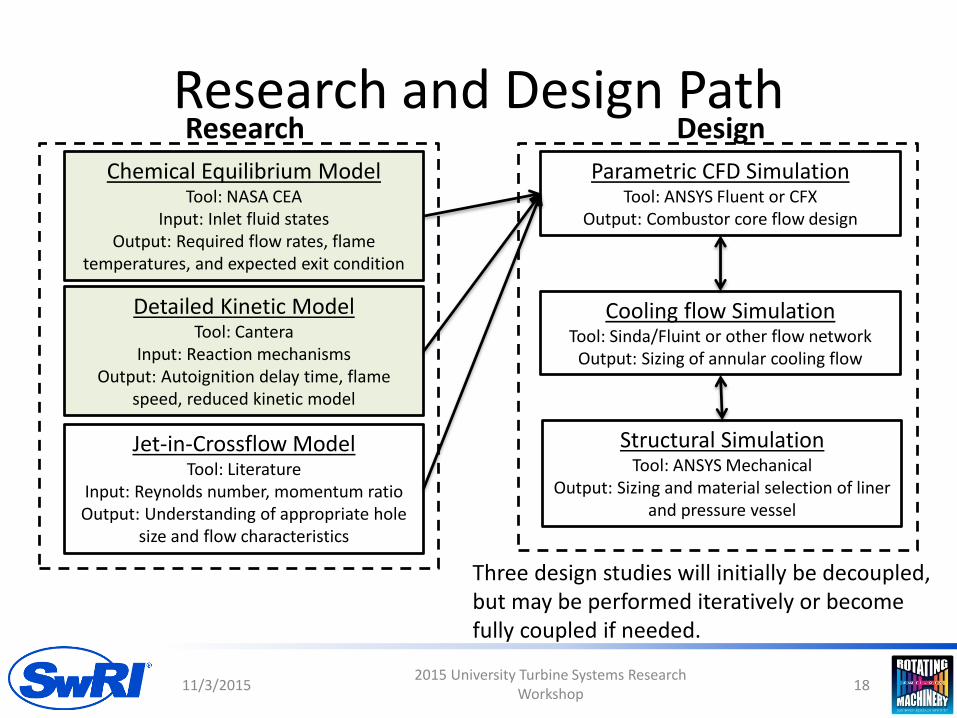
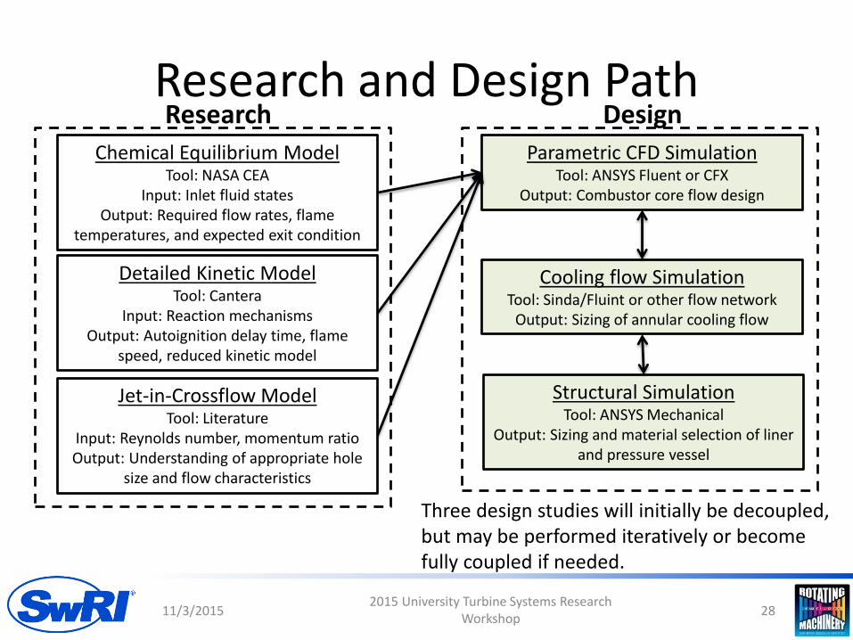
Research and Design Path
11/3/20152015 University Turbine Systems Research
Workshop18
Chemical Equilibrium ModelTool: NASA CEA
Input: Inlet fluid statesOutput: Required flow rates, flame
temperatures, and expected exit condition
Detailed Kinetic ModelTool: Cantera
Input: Reaction mechanismsOutput: Autoignition delay time, flame
speed, reduced kinetic model
Jet-in-Crossflow ModelTool: Literature
Input: Reynolds number, momentum ratioOutput: Understanding of appropriate hole
size and flow characteristics
Parametric CFD SimulationTool: ANSYS Fluent or CFX
Output: Combustor core flow design
Research Design
Cooling flow SimulationTool: Sinda/Fluint or other flow network
Output: Sizing of annular cooling flow
Structural SimulationTool: ANSYS Mechanical
Output: Sizing and material selection of liner and pressure vessel
Three design studies will initially be decoupled, but may be performed iteratively or become fully coupled if needed.

Kinetic Model: Motivation
• The fundamental size of the combustor is governed by the timescale of chemical reactions
• The chemical reaction kinetics determine how fast fuel oxidation occurs
– A detailed chemical kinetic model is required to size the combustor
– A reduced chemical kinetic model is required for detailed flow-field design in CFD
11/3/20152015 University Turbine Systems Research
Workshop19

Chemical Mechanisms
• A set of species, chemical equations, and reaction rate equations is called a mechanism– Reaction rate is a function of temperature and reactant concentrations
• Actual hydrocarbon combustion is complex process involving a multitude of intermediate reactions and species– Modeling the complete process is not practical– Mechanisms in the literature are approximations that use a subset of species and reactions– Adding species and reactions improves predictions and provides more information, but with
non-linear increase to computational cost
11/3/20152015 University Turbine Systems Research
Workshop20
CH4 + 2 O2 → 2 H2O + CO2 𝑟 = 𝐴𝑇𝑛𝑒−𝐸𝑎𝑅𝑇 𝐶𝐻4
𝑎 𝑂2𝑏
Species: 4 Reactions: 1
CH4 + 1.5 O2 → 2 H2O + CO
CO + 0.5 O2 → CO2
𝑟1 = 𝐴1𝑇𝑛1𝑒−
𝐸𝑎1𝑅𝑇 𝐶𝐻4
𝑎1 𝑂2𝑏1
𝑟2 = 𝐴2𝑇𝑛2𝑒−
𝐸𝑎2𝑅𝑇 𝐶𝑂 𝑎2 𝑂2
𝑏2
Species: 5 Reactions: 2
Sample Methane Oxidation Mechanisms for Same Overall Reaction
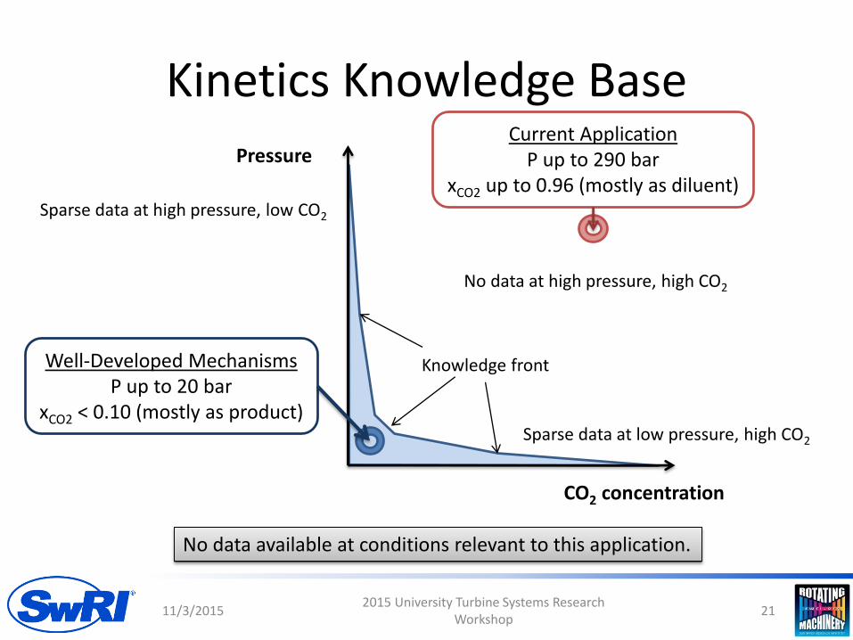
Kinetics Knowledge Base
11/3/20152015 University Turbine Systems Research
Workshop21
CO2 concentration
PressureCurrent Application
P up to 290 barxCO2 up to 0.96 (mostly as diluent)
Well-Developed MechanismsP up to 20 bar
xCO2 < 0.10 (mostly as product)Sparse data at low pressure, high CO2
Sparse data at high pressure, low CO2
No data at high pressure, high CO2
Knowledge front
No data available at conditions relevant to this application.

Modeling Strategy• No available kinetic model is validated for this application
– Forced to use extrapolation
• Select a set of detailed models that are validated for low pressure and low CO2concentration– Other mechanism criteria
• > 102 reactions: More detailed models may have better extrapolation capability• < 103 reactions: Too large of a mechanism will be impractical to validate and execute in design studies
– Mechanisms evaluated
• Compare model predictions at validated conditions– Autoignition, flame speed, and residual CO
• Compare model results at supercritical oxyfuel combustor conditions• Select best performer for use in this project with appropriate uncertainty range • Cantera 2.1.2 is used as the modeling environment
11/3/20152015 University Turbine Systems Research
Workshop22
Mechanism Species Count Reaction Count
GRI-Mech 3.0 [1] 53 325
USC-II [2] 112 784
San Diego 2014-10-04 [3] 50 247
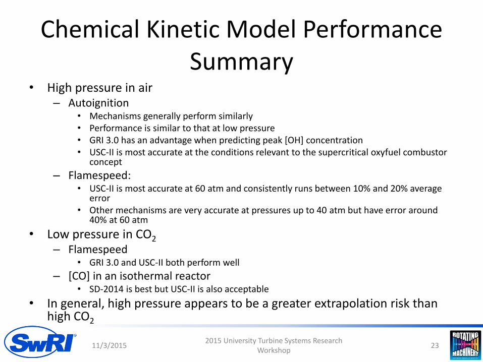
Chemical Kinetic Model Performance Summary
• High pressure in air– Autoignition
• Mechanisms generally perform similarly• Performance is similar to that at low pressure• GRI 3.0 has an advantage when predicting peak [OH] concentration• USC-II is most accurate at the conditions relevant to the supercritical oxyfuel combustor
concept
– Flamespeed:• USC-II is most accurate at 60 atm and consistently runs between 10% and 20% average
error• Other mechanisms are very accurate at pressures up to 40 atm but have error around
40% at 60 atm
• Low pressure in CO2
– Flamespeed• GRI 3.0 and USC-II both perform well
– [CO] in an isothermal reactor• SD-2014 is best but USC-II is also acceptable
• In general, high pressure appears to be a greater extrapolation risk than high CO2
11/3/20152015 University Turbine Systems Research
Workshop23
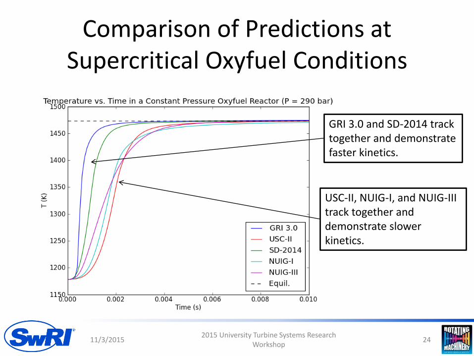
Comparison of Predictions at Supercritical Oxyfuel Conditions
11/3/20152015 University Turbine Systems Research
Workshop24
GRI 3.0 and SD-2014 track together and demonstrate faster kinetics.
USC-II, NUIG-I, and NUIG-III track together and demonstrate slower kinetics.

Comparison of Predictions at Supercritical Oxyfuel Conditions
11/3/20152015 University Turbine Systems Research
Workshop25
Initial phase(CH4 consumption and CO production)
2 ms
Second phase(majority of
CO consumption)2-6 ms
Third phase(remaining
CO consumption)> 6 ms

Mechanism Selection
• Primary selection criterion is accurate prediction of the overall reaction time scales– Drives the combustor design– More important than other details such as peak
concentration values
• USC-II is the clear choice based on this criterion– Most accurate in highest pressure flamespeed and
autoignition validation comparisons
• USC-II also had good to adequate performance in low pressure CO2 studies
• USC-II predictions should carry +/- 50% uncertainty in this application
11/3/20152015 University Turbine Systems Research
Workshop26

Reduced Order Model
• For incorporation into a CFD model a reduced order model was developed
• Equations based on Arrhenius rate equation were tuned to match USC-II model predictions
– Match autoignition delay
– Match residual CO levels
– Overall time to complete reaction
11/3/20152015 University Turbine Systems Research
Workshop27
Research and Design Path
11/3/20152015 University Turbine Systems Research
Workshop28
Chemical Equilibrium ModelTool: NASA CEA
Input: Inlet fluid statesOutput: Required flow rates, flame
temperatures, and expected exit condition
Detailed Kinetic ModelTool: Cantera
Input: Reaction mechanismsOutput: Autoignition delay time, flame
speed, reduced kinetic model
Jet-in-Crossflow ModelTool: Literature
Input: Reynolds number, momentum ratioOutput: Understanding of appropriate hole
size and flow characteristics
Parametric CFD SimulationTool: ANSYS Fluent or CFX
Output: Combustor core flow design
Research Design
Cooling flow SimulationTool: Sinda/Fluint or other flow network
Output: Sizing of annular cooling flow
Structural SimulationTool: ANSYS Mechanical
Output: Sizing and material selection of liner and pressure vessel
Three design studies will initially be decoupled, but may be performed iteratively or become fully coupled if needed.

COMBUSTOR DEVELOPMENT
11/3/20152015 University Turbine Systems Research
Workshop29

Operating Requirements
• Combustor inlet conditions
– 200 to 300 bar
– 750 to 1000 C
• Natural Gas or Syngas with CO2 diluent
– Not concerned about NOx
11/3/20152015 University Turbine Systems Research
Workshop30
ThermalInput
Cooler
Low TemperatureRecuperater
High TemperatureRecuperater
Turbine
Compressor
Recompressor
Combustor

Auto Ignition Flame Stabilization
• Conventional low temperature combustors require submerged components– Fuel/air pre-mixing – Flame stabilization
• Requirements do not apply to high inlet temperature oxy-combustors– NOx emissions are not a concern – Inlet temperature above the fuel’s
autoignition temperature
• Autoignition can be used to stabilize the flame without submerged components– Fuel/O2 will spontaneously ignite after
a short delay time– No recirculation zones are required
• Additional research is needed to verify autoignition properties at high pressure with CO2 diluent
11/3/20152015 University Turbine Systems Research
Workshop31
References1. L. J. Spadacinni and M. B. Colket, “Ignition Delay Characteristics of Methane Fuels,” Progress in Energy and Combustion Science, Vol. 20 No. 5, pp. 431-460, 1994.
Based on correlation from [1]

Mixing Theory• Fuel and oxidizer must thoroughly mix
– Homogenous output condition
• The tee mixer, or jet-in-crossflow (JICF) is a simple, highly effective, and well-documented mixing device without submerged parts– Counter-rotating vortex pair entrains
fluid
• Flow physics for JICF is complicated by turbulent structures– Steady RANS was used for modeling– Known deficiency in modeling the
unsteady behavior
11/3/20152015 University Turbine Systems Research
Workshop32
References1. Kelso, et al. “An experimental study of round jets in cross-flow,” J.
Fluid Mech, vol. 306, 111-144, 1996.2. “Jet Injection for Optimum Pipeline Mixing,” Encyclopedia of Fluid
Mechanics, vol. 2, Ch. 25, Gulf Publishing, 1986.
[1]
[2]

Initial Combustor Concept
11/3/20152015 University Turbine Systems Research
Workshop33

CFD Geometries
11/3/20152015 University Turbine Systems Research
Workshop34
4 Hole 45°Clocked
4 Hole 11.25°Clocked
4 Hole Aligned
• CFD simulation using reduced reaction mechanism
• Explore injector hole location, velocity, and size– Thermal conditions inside the
combust
– Instrumentation placement
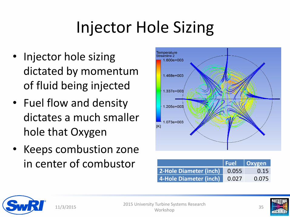
Injector Hole Sizing
Fuel Oxygen2-Hole Diameter (inch) 0.055 0.154-Hole Diameter (inch) 0.027 0.075
11/3/20152015 University Turbine Systems Research
Workshop35
• Injector hole sizing dictated by momentum of fluid being injected
• Fuel flow and density dictates a much smaller hole that Oxygen
• Keeps combustion zone in center of combustor

Sample Result: 45° Clocked• Four fuel, four oxygen injectors, 45°
angle between ports• High max temperature
– Highest temperature are located away from the walls
• Rapid combustion, relatively good mixing
11/3/20152015 University Turbine Systems Research
Workshop36
1000
1100
1200
1300
1400
1500
1600
0.00 0.20 0.40 0.60 0.80 1.00
Tem
pe
ratu
re (
K)
Distance (m)
Ave Temperature (K)
Max Temperature (K)
4 Hole 45°Clocked

Sample Result: 11.25° Clocked
11/3/20152015 University Turbine Systems Research
Workshop37
1000
1100
1200
1300
1400
1500
1600
1700
1800
1900
2000
0.00 0.20 0.40 0.60 0.80 1.00
Tem
pe
ratu
re (
K)
Distance (m)
Ave Temperature(K)
4 Hole 11.25°Clocked
• Four fuel, four oxygen injectors, 11.25° angle between ports
• Very high max temperature, which is in contact with walls

Refined Design: Fuel Injection 24in Upstream
• Fuel well mixed throughout combustor before oxygen
• Allows hydrocarbon “cracking” before oxygen injection
• Cool max temperatures
• Very good mixing at outlet
• Very low unburnt fuel percentage
11/3/20152015 University Turbine Systems Research
Workshop38
1000
1100
1200
1300
1400
1500
1600
0.00 0.50 1.00 1.50 2.00
Tem
pe
ratu
re (
K)
Distance (m)
Ave Temperature (K)
Max Temperature (K)

Refined Design Concept
11/3/20152015 University Turbine Systems Research
Workshop39
Fuel injection plane O2 injection plane
Distributed reaction zone(stabilized by autoignition)
800°C CO2 inlet
Cold CO2 – cooling
Pressure vessel
Metal support liner
Fuel premixing zone(jet-in-crossflow)
Four 90°fuel injection jets
Four 90°O2 injection jets
Centerline
Refractory Liner

Instrumentation
• Thermocouples
• Pressure
– Static
– Dynamic
• Optical access
• Gas sampling and analysis
11/3/20152015 University Turbine Systems Research
Workshop40
Hot Inlet Air
Combustion Processes
Cooling CO2

WRAPUP
11/3/20152015 University Turbine Systems Research
Workshop41

Status Summary
• Program Objectives– Advance fossil based sCO2 power cycles– Reduce technical risk for direct fired oxy-combustion
• Progress to Date– System Design and Thermodynamic Analysis– Kinetic Models– Bench Scale Testing– Auto-ignition based Combustor Design
• Moving Forward– Additional Combustor Concepts– Phase II Demonstration Concept
11/3/20152015 University Turbine Systems Research
Workshop42

QUESTIONS?
11/3/20152015 University Turbine Systems Research
Workshop43

Component SpecificationsComponent Specifications
Compressor Polytropic η: 0.85, Mechanical η: 0.95
Isothermal Compressor 3 stage Isothermal Compressor, T Ratio: +5°C/stage
Refrigeration % Carnot: 0.45, Ambient Temp: 15°C
Cryo-Pump Pump η: 0.55, Mechanical η: 0.95
CO2 Pump (Non Cryo) Pump η: 0.75, Mechanical η: 0.95
Heat Exchanger Pinch ∆T: 10°C, ∆P: -1 bar
CH4 Delivery Compressor Polytropic η: 0.85, Mechanical η: 0.98
O2 Pump Pump η: 0.55, Mechanical η: 0.94
ASU ASU ~300 kW-hr/ton if Liquid, ~250 kW-hr/ton if gas
Turbine Isentropic η: 0.92, Mechanical η: .99
Pipe Line CO2 Compressor Polytropic η: 0.85, Mechanical η: .98
Cooling Tower Cooling tower: 0.06 kW/Ton, Minimum Temp: 20°C
Water Chiller Cooling: 0.6kW/Ton
11/3/20152015 University Turbine Systems Research
Workshop44