Embed Size (px)
Citation preview

High efficiency system design with Infineon power discretes-Infineon CoolMOSTM,OptiMOSTM, IGBT and SiC diode
Vincent Zeng(曾伟权 )
System application engineer
Infineon Technologies China

10.02.2010
Infineon Products help reduce losses along the Entire Energy Distribution Chain
AC/AC
AC/DC/AC
Motor Drives,
TractionAC/DC/AC
Power Supply
AC/DC
Point of Load
DC/DC
~10%
Losses
Losses
Losses
Losses
Losses
Energy Generation
Energy Distribution
Energy Consumption

Mature Super Junction Technology Mature Super Junction Technology
n epi
p +
n
D
p
n +sub
SG
Blocking state
n epi
D
p -
n +sub
GS
p +
n
p
Conducting state
---
--
-
10.02.2010
The evolution on power semiconductor is never end
1200V SiC JFET1200V SiC JFET
Bi-Polar Boost like Bi-Polar Boost like Structure SiC DiodeStructure SiC Diode
New Packaging ConceptNew Packaging Concept<1mm HV ThinPAK, TO-247 High Creepage<1mm HV ThinPAK, TO-247 High Creepage
New die attachment methodNew die attachment methodDiffusion soldering technologyDiffusion soldering technology
Emitter
Gate
Collector p+
n+
p+
n-(substrate)
n (fieldstop)
Emitter
Gate
Collector p+
n+
p+
n-(substrate)
n (fieldstop)
Trench+ Field Stop IGBTTrench+ Field Stop IGBT

10.02.2010 Copyright © Infineon Technologies 2010. All rights reserved.
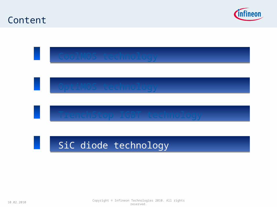
Content
CoolMOS technology CoolMOS technology
TrenchStop IGBT technology TrenchStop IGBT technology
SiC diode technology SiC diode technology
OptiMOS technology OptiMOS technology

18.04.23
What is CoolMOS™ technology
On state:
Reduction of resistance of epitaxial layer by high doped n-columns
Higher doping level in n-type drift region results in lower Rds(on)
Blocking state:
Compensation of additional charge by adjacent p-columns
Half of active chip area is covered by p-columns
During blocking state the p-column compensates the charge of the adjacent n-column resulting in high breakdown voltage at an area specific on-resistance below the silicon limit!
Source
Gate
Drain n+
n+
p+
nepi
Standard MOSFET
Source
Gate
Drain n+
n+
p+
pnepi
CoolMOS™

18.04.23
CoolMOSCoolMOSTMTM – Technology leader in high voltage MOSFETs – Technology leader in high voltage MOSFETsCoolMOSCoolMOSTMTM – Technology leader in high voltage MOSFETs – Technology leader in high voltage MOSFETs
High voltage MOSFET in 500V, 600V,
650V, 800V and 900V
Offers a significant reduction of
conduction and switching losses
Enables high power density and
efficiency for superior power
conversion systems
Best-in-class price/performance ratio
A short description of CoolMOS™
0
5
10
15
20
25
30
400 500 600 700 800 900 1000
Ron x A [mm2]
New horizonsfor high voltageapplications
Standard MOSFET Ron x A ~ V(BR)DSS
2,4...2,6
CoolMOSTM
Fig.: A near-linear relationship between Rds(on) and V(BR)DSS indicates the significant difference between CoolMOS and conventional MOSFET
10.02.2010 Page 7
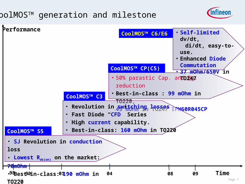
Performance
98 99 01 04 Time
CoolMOSTM CP(C5)
• 50% parastic Cap. and Qg. reduction• Best-in-class : 99 mOhm in TO220,
45 mOhm in TO247 IPW60R045CP
CoolMOSTM S5
• SJ Revolution in conduction loss
• Lowest Rds(on) on the market: 70mOhm
• Best-in-class: 190 mOhm in TO220
08 09
• Self-limited dv/dt, di/dt, easy-to-use.• Enhanced Diode
Commutation• 37 mOhm/650V in
TO247
CoolMOSTM C6/E6
CoolMOSTM generation and milestone
CoolMOSTM C3
• Revolution in switching losses• Fast Diode “CFD” Series• High current capability.• Best-in-class: 160 mOhm in TO220

10.02.2010
CoolMOS™ C6 high efficiency @ affordable costs
CoolMOS™ C6 is the new generation of Infineon´s market leading high voltage power MOSFET´s designed according to
the revolutionary superjunction (SJ) principle
The new 600V&650V C6 portfolio provides all benefits of a fast switching SJ MOSFET while not sacrificing ease of use

10.02.2010
CoolMOS™ C6 high efficiency @ affordable costs
Features: Features:
lower area specific on-state resistance (RDS(on))*A)
reduced energy stored in output capacitance (Eoss)
high body diode ruggedness
reduced reverse recovery charge (Qrr)
Benefits:Benefits:
lower costs compared to previous CoolMOS™ generations
proven CoolMOS™ quality combined with high bodydiode ruggedness guarantee outstanding reliability
easy control of switching behavior
low switching losses (due to low Eoss)

CoolMOS C6 reduced energy stored in output capacitance
CoolMOS™C6 shows the best Figure-of-merit Ron E∗ oss
Low energy stored in output capacitance make make CoolMOS™C6 the right choice for hard switching applications.
0
2
4
6
8
10
12
0 100 200 300 400 500Vds [V]
Eo
ss
[µ
J]
IPP60R190C6
SPP20N60C3
IPP60R199CP

10.02.2010
CoolMOS™ C6 600V efficiency measurement
Efficiency comparison CoolMOS C6 versus C3Efficiency comparison CoolMOS C6 versus C3
Ease of useEase of use & good efficiencygood efficiency especially
in light load conditions!
70%72%74%76%78%80%82%84%86%
0 100 200 300 400 500
Pout [W]
Eff
icie
ncy
[%
]
2 xIPP60R190C6Rg,ext=3.3 Ohm2 x SPP20N60C3Rg,ext=3.3 Ohm
-0.1%0.0%0.1%0.2%0.3%0.4%0.5%0.6%0.7%
0 100 200 300 400 500Pout [W]
Eff
icie
nc
y d
iffe
ren
ce
C6
vs
C3
[%
]

DCM PFC stage, 150W, AC in 90V
Ecellent price performance ration, ease of use and good efficiency especially in light load conditions make 650V CoolMOS™C6 the right choice for hard switching applications.
CoolMOS™ C6 650V efficiency measurement
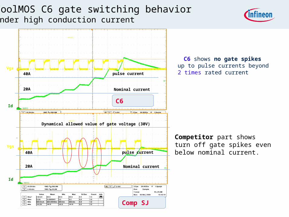
C6 shows no gate spikes up to pulse currents beyond 2 times rated current
C6
Nominal current
pulse current40A
20A
Vgs
Id
Comp SJ
Nominal current
pulse current40A
20A
Dynamical allowed value of gate voltage (30V)
Vgs
Id
Competitor part shows turn off gate spikes even below nominal current.
CoolMOS C6 gate switching behavior Under high conduction current

10.02.2010
Hard commutation of body diode
-30
-20
-10
0
10
20
30
40
0 0.2 0.4 0.6 0.8 1time [µs]
dra
in c
urr
en
t I
DS
[A
]
SPP20N60C3
IPP60R190C6
SPP20N60CFD
CoolMOS™ C6 shows less reverse recovery charge than C3 and better softness than CFD
04/18/23 Page 15
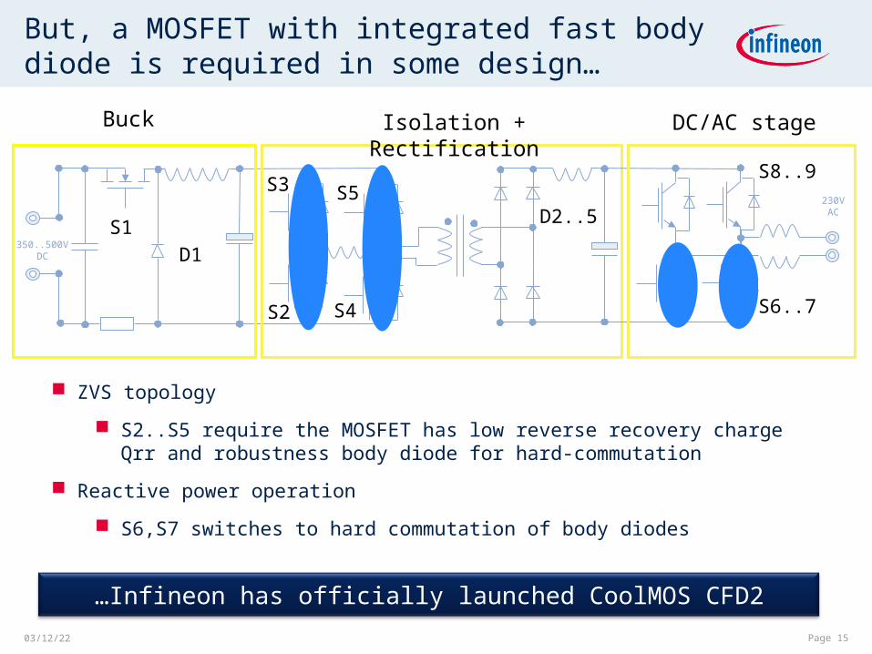
350..500V DC
230VAC
Isolation + RectificationBuck DC/AC stage
S1
D1
S2
S3
D2..5
S6..7
S8..9
But, a MOSFET with integrated fast body diode is required in some design…
S5
S4
ZVS topology
S2..S5 require the MOSFET has low reverse recovery charge Qrr and robustness body diode for hard-commutation
Reactive power operation
S6,S7 switches to hard commutation of body diodes
…Infineon has officially launched CoolMOS CFD2

Set date Page 16
Main differences between CFD and CFD2
CFD2 is a 650V class MOSFET (CFD is 600V)
Better light load efficiency due to reduced gate charge
Softer commutation behavior and therefore better EMI behavior
CFD2 offers customers a new cost down roadmap
-5
0
5
10
15
20
0.25 0.3 0.35 0.4 0.45 0.5
time [µs]
I d [
A]
Ids_SPW47N60CFD
Ids_IPW65R080CFD
CFD: fast switching of voltage or current i.e. di/dt or dv/dt(main causes of EMI)
CFD2: softer commutation reduces this problem saving customer time and money in designing in the part

Voltage overshoot CFD2 vs. CFD vs. Competition
0
200
400
600
800
0 100 200 300 400 500
U [
V]
t [µs]
T=25°C; If=20A; Rg,d=5.6 Ohm; Ugs=13V
SPW47N60CFD
IPW65R080CFD
Comp2 43A676V
569V
452V
224V less overshoot with CFD2 for reliable systems

CoolMOS™ C6/E6 Portfolio 600V
0.099 Ω35 A
0.125 Ω30 A
0.16 Ω24 A
0.19 Ω20 A
0.28 Ω15 A
0.38 Ω11 A
0.45 Ω9.5 A
0.52 Ω 8 A
0.6 Ω7.3 A
0.75 Ω6.2 A
0.95 Ω4.5 A
1.4 Ω3.2 A
2 Ω2.5 A
3.3 Ω 1.8 A
TO-252 D-Pak [D]
TO-263D²PAK [B] TO-220 [P]
TO-220Fullpak [A]
TO-262I²-PAK [I] TO-247 [W]
IPW60R070C6
IPW60R099C6
IPW60R160C6
IPW60R190E6
IPW60R280E6
IPA60R160C6
IPA60R190E6
IPA60R280E6
IPA60R380E6
IPA60R450E6
IPA60R520E6
IPA60R600E6
IPA60R950C6
IPP60R160C6
IPP60R190E6
IPP60R280E6
IPP60R380E6
IPP60R450E6
IPP60R520E6
IPP60R600E6
IPP60R950C6
IPP60R750E6
IPP60R1k4C6
IPI60R190C6
IPI60R280C6
IPI60R380C6
IPB60R160C6
IPB60R190C6
IPB60R280C6
IPB60R380C6
IPB60R600C6
IPB60R950C6
IPD60R380C6
IPD60R450E6
IPD60R520C6
IPD60R600E6
IPD60R950C6
IPD60R750E6
IPD60R1k4C6
IPD60R3k3C6
IPP60R099C6 IPA60R099C6
0.07 Ω47 A
IPW60R125C6IPP60R125C6 IPA60R125C6
IPB60R099C6
IPD60R2k0C6
0.041 Ω77 A
IPW60R041C6
IPA60R750E6

CoolMOS™ C6 Portfolio 650V
IPW65R037C6: 650V 37mΩ TO247

CoolMOS™ E6 650V Portfolio

650V CoolMOS™ CFD2 Portfolio
Set date Copyright © Infineon Technologies 2010. All rights reserved. Page 21
600 mΩ, 80 mΩ, and 41 mΩ are already launched.420 mΩ to 110 mΩ will be launched around February to March 2011.1400 mΩ and 950 mΩ will be launched around May 2011.

10.02.2010 Copyright © Infineon Technologies 2010. All rights reserved.
Content
CoolMOS technology CoolMOS technology
TrenchStop IGBT technology TrenchStop IGBT technology
SiC diode technology SiC diode technology
OptiMOS technology OptiMOS technology
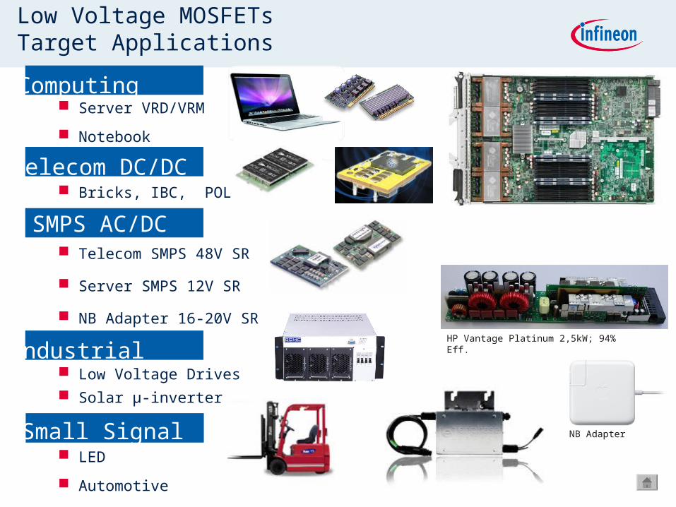
Server VRD/VRM
Notebook
Bricks, IBC, POL
Telecom SMPS 48V SR
Server SMPS 12V SR
NB Adapter 16-20V SR
Low Voltage Drives Solar µ-inverter
LED
Automotive
SMPS AC/DC
Low Voltage MOSFETs Target Applications
Computing
Telecom DC/DC
Industrial
Small Signal
HP Vantage Platinum 2,5kW; 94% Eff.
NB Adapter

23/4/18
Beyond the silicon limit
0 20 40 60 80 100 120 140 160 600 800 1000
n
orm
aliz
ed
on
-re
sist
an
ce
breakdown voltage [V]
Si-limit (die)
Si-limit in SuperSO8
Si-limit in TO-220
IFX-products
OptiMOS™ CoolMOS™

Set date
Infineon OptiMOSTM
(25V~250V) Efficiency
Lowest RDS(on) and FOM RDS(on) *Qg against competitors
Infineon Next Best Competitor
V
0
1000
2000
3000
4000
5000
6000
25 30 40 60 75 80 100 120 150 200 250 V
FOM RDS(on) *QgRDS(on)
0
40
80
120
160
25 30 40 60 75 80 100 120 150 200 250
CanPAK M SuperSO8 D²PAK-7 pin D²PAK TO-220
80VBSB044N08NN3 G
4.4 mOhmBSC047N08NS3 G
4.7mOhmIPB019N08N3 G
1.9mOhmIPB025N08N3 G
2.5mOhmIPP028N08N3 G
2.8mOhm
100VBSB056N10NN3 G
5.6mOhmBSC060N06NS3 G
6.0mOhmIPB025N10N3 G
2.5mOhm IPB027N10N3 G
2.7mOhmIPP030N10N3 G
3.0mOhm
120VBSC077N12NS3 G
7.7mOhmIPB036N12N3 G
3.6mOhmIPB038N12N3 G
3.8mOhmIPP041N12N3 G
4.1mOhm
150VBSB150N15NZ3 G
15mOhmBSC190N15NS3 G
19mOhmIPB065N15N3 G
6.5mOhmIPB072N15N3 G
7.2mOhmIPP075N15N3 G
7.5mOhm
200VBSC320N20NS3 G
32mOhm
IPB107N20N3 G10.7mOhm
IPP110N20N3 G11.0mOhm
250VBSC600N25NS3 G
60mOhm
IPB200N25N3 G20.0mOhm
IPP200N25N3 G20.0mOhm
Best-in-class

DPAKDPAK
SO8SO8
D²PAK/TO220D²PAK/TO220
Packag
e Size
Performance
SuperSO8SuperSO8
S3O8S3O8
Package resolution
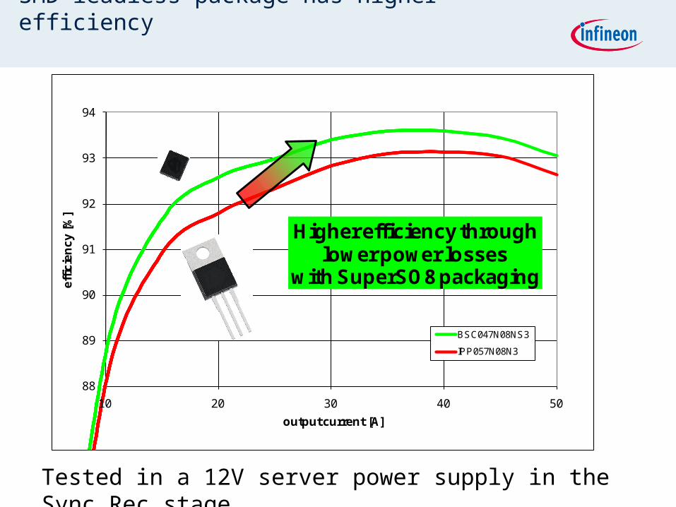
SMD leadless package has higher efficiency
88
89
90
91
92
93
94
10 20 30 40 50
eff
icie
nc
y [
%]
output current [A]
BSC047N08NS3
IPP057N08N3
Higher efficiency throughlower power losses
with SuperSO8 packaging
Tested in a 12V server power supply in the Sync Rec stage

18.04.23
Overshoot comparison same chip
45 V
50 V
55 V
60 V
65 V
70 V
75 V
10 A 15 A 20 A 25 A 30 A 35 A 40 A 45 A 50 A
output current
ove
rsh
oo
t
SSO8
TO220 low Ls
TP220 high Ls
SMD leadless has lower voltage overshoot
Longer electrical MOSFET connections mean
¬ Higher inductance
¬ Higher voltage stress for the MOSFET

18.04.23
Adapterboard TO220 to SuperSO8
Gate
Drain
Source
Source
Drain
Gate
What do I need this board for?- quick replacement of TO220 in existing designs- electrical verification of SuperSO8
Sync Rec MOSFETs: Q1, Q2MOSFET – Gate Resistor: R1RCD Snubber – Diode: D3RCD Snubber – Capacitor: C3RCD Snubber – Discharge Resistor: R3Connectors for RCD Snubber: AScrew holes

10.02.2010 Copyright © Infineon Technologies 2010. All rights reserved.
Content
CoolMOS technology CoolMOS technology
TrenchStop IGBT technology TrenchStop IGBT technology
SiC diode technology SiC diode technology
OptiMOS technology OptiMOS technology

23/4/18
How to improve the standard IGBT-technology?
n (fieldstop)
Concept of thin wafer with Fieldstop-technology reduces VCE(sat) dramatically Reduction of Conduction Losses for higher Efficiency and improved thermal properties
Reduction of Swtiching Losses for higher Efficiency
Introduction of trench gate technology reduces VCE(sat) further Reduction of Conduction Losses for higher Efficiency
Emitter
Gate
Collector p+
n+
p+
n-(substrate)
n (fieldstop)
Emitter
Gate
Collector p+
n+
p+
n-(substrate)
n (fieldstop)

18.04.23
TrenchStopTM in thin wfr technology with carrier profile optimized for fast switching
IGBT Technology selection
High Speed 3

18.04.23
New Highspeed 3 IGBT technology
Applikationsbewertung
Trade-off diagram Ic = In/2, Tj= 150°C
12
14
16
18
20
22
24
26
28
30
32
1.2 1.3 1.4 1.5 1.6 1.7 1.8 1.9 2.0 2.1 2.2 2.3 2.4
VCEsat / V
Eo
ff /
mJ/
A
SKB15N60HS
Competitor B
Competitor A
IKP15N60T
IGW40N60H3HighSpeed3
Trade-off diagram 150°C
SKW25N120
IKW25T120
Competitor A
IKW25N120T2
IKW25N120H3
Competitor ACompetitor A
Competitor B
0.00
0.02
0.04
0.06
0.08
0.10
0.12
0.14
0.16
2 2.4 2.8 3.2 3.6 4 4.4
VCEsat / V
Eo
ff /
mJ
/A
High Speed 3
Trench gate+ Field Stop offers superior trade-off
Reduced switching losses for switching Frequencies above 30 kHz
Soft switching behaviour
Optimized diode for target applications

18.04.23
New highspeed 3 IGBT switching behavior
Elimination of tail current at high temperature…
…for MOSFET-like switching behavior
High Speed 3
Std IGBT3
High Speed 3
CoolmosC3

23/4/18
Powerloss comparisonSimulation with IPOSIMTM
In comparison with the previous generation TrenchStop2, the HighSpeed 3 shows 30% reduction in switching losses and only 16% increase in conduction losses.
The HighSpeed 3 shows approx 10% lower losses than the best competitor,
setting benchmark performance.
3-phase inverterVbus=600VFsw=20kHzIload=40A
3-phase inverterVbus=600VFsw=20kHzIload=40A

23/4/18
Turn-off Waveform comparison
IKW30N60H3 IGBT Best competitor
Smooth switching waveforms
Low dV/dt and dI/dt for reduced EMI
Ic=5A Vce=400V
Vge=+15/0V

18.04.23
Infineon’s High Speed 3 IGBT Portfolio600V and 1200V Product Family
Continuous collector current
at TC =100°C
20A20A
Sin
gle
IG
BT
Sin
gle
IG
BT
30A30A
TO-247TO-220
Du
oP
ac
k ™
Du
oP
ac
k ™ 20A20A
30A30A
50A50A
IGP20N60H3IGP20N60H3
IGP30N60H3IGP30N60H3
IKW20N60H3IKW20N60H3
IKW30N60H3IKW30N60H3
IKW40N60H3IKW40N60H340A40A
IGW50N60H3IGW50N60H3
IGW40N60H3IGW40N60H340A40A
15A15A IKW15N120H3IKW15N120H3
IKW25N120H3IKW25N120H3
IKW40N120H3IKW40N120H3
15A15A IGP15N120H3IGP15N120H3
IGP25N120H3IGP25N120H325A25A
IGP40N120H3IGP40N120H3
TO-247
600V 1200V
25A25A
IGB20N60H3*IGB20N60H3*
IGB30N60H3*IGB30N60H3*
TO-263
IKB20N60H3*IKB20N60H3*
IKB30N60H3*IKB30N60H3*
IKP20N60H3*IKP20N60H3*
IKP20N60H3*IKP20N60H3*
IKW50N60H3IKW50N60H350A
75A75A IKW75N60H3*IKW75N60H3*
√ Devices are fully released! * Engineering samples October 2010

TrenchStop IGBT for low switching frequency
Continuous collector current
at T C =100°C
TO-247
IKW20N60TIKW20N60T
Du
oP
ack
™D
uo
Pac
k ™
IKW30N60TIKW30N60T
20A20A
30A30A
IKW50N60TIKW50N60T
IKW75N60TIKW75N60T
50A50A
75A75A
Continuous collector current
at T C =100°C
TO-247
Du
oP
ack™ 15A
25A
40A
IKW15N120T2
IKW25N120T2
IKW40N120T2
Vce(sat) @25°C=1.5V Vce(sat) @25°C=1.75V
Polarity selection switch
@50Hz switching frequency
conduction loss dominated
10.02.2010 Copyright © Infineon Technologies 2010. All rights reserved.
Content
CoolMOS technology CoolMOS technology
TrenchStop IGBT technology TrenchStop IGBT technology
SiC diode technology SiC diode technology
OptiMOS technology OptiMOS technology

23/4/18
This is a huge application potential for Schottky diode in high voltage application, but …
… today’s voltage range of Schottky ends at 250V
Reasons:
very high leakage currents (reverse loss~forward loss)
on resistance increases with Ubr2.5 and increasing the area
again increases the reverse loss
With SiC Schottky diodes the range can be extended exceeding 1000V

23/4/18
SiC feature fast forward conductionReduce the Maximum VDS Stress of Power MOSFET!
Replacement of diode allows spike reduction of more than 100 V
Full switching speed range of boost MOSFET useable for highest efficiency
Very low Vds spikewith SiC Schottky diode
Improved gate waveform
VDS spike up to 600 V with extremely fast switching boost MOSFET and competitors tandem diode
High losses and EMI problems
Using competitor tandem diode Using SiC Schottky diode
Due to unipolar nature of shottky,No need for forward recorver
time to get conductive
Vgs
VgsVds
Vds

23/4/18
Zero reverse recovery charge only with unipolar devices… SiC Schottky diode
Not possible with Si technology at 600 V rating……therefore SiC Schottky diode concept required!
-6
-4
-2
0
2
4
6
0.05 0.1 0.15 0.2 0.25 0.3
Time [µs]
I [A
]
SiC Schottky diode: 6A, 600VSi-pn Tandem diode 8A, 600VStandard Ultrafast 5A, 600V pn-diode
T=125°C, UAK=400V
IF=6A, di/dt=200A/ms

23/4/18
Switching loss of SiC keep constant vs Io,Rg and Tc
Advantages of your design: switching loss does not change with load condition, Rg of Boost MOSFET and temperature.

23/4/18
Ruggedness and improved surge current capability @ elevated Tc (Infineon Patented)
0
5
10
15
20
25
30
35
40
0.00 2.00 4.00 6.00 8.00 10.00 12.00 14.00VF (V)
I F (A
)
curr
ent s
urge
cap
abili
tyLow p
ower dissip
ation
at opera
tion m
ode
bipolar pn diodeforward characteristic
Ideal characteristic: merged pn-
Schottky diode
unipolar diode forward
characteristic

23/4/18
SiC diode 3rd generation Package updated
Average creepagedistance 1.78mm
Average creepagedistance 3.64mm
TO-220 real 2pin package
2G 3G
Creepage distance improved by a factor of 2
Besides, SiC diode in SMD package is available
23/4/18
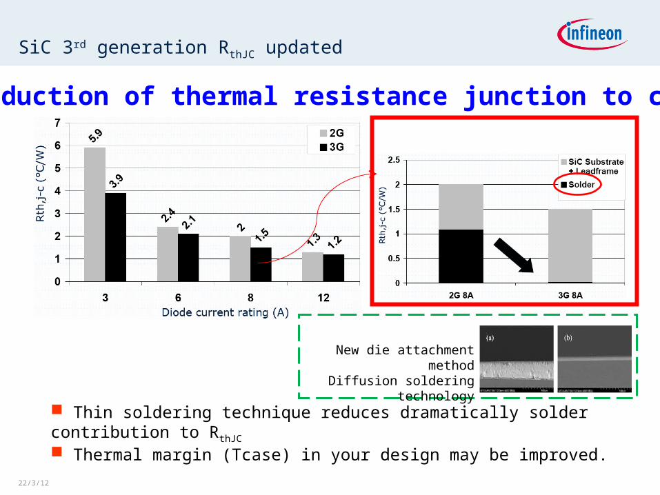
SiC 3rd generation RthJC updated
Thin soldering technique reduces dramatically solder contribution to RthJC Thermal margin (Tcase) in your design may be improved.
Reduction of thermal resistance junction to case
New die attachment methodDiffusion soldering technology

23/4/18
SiC 3rd generation stored Qc updated
3G offers ever lowestQc(Qrr) per givencurrent rating in themarket
Enable higher switching frequency and smaller form-factor design
Reduction of device capacitances

23/4/18
Voltage P/N IF QC Package Package
IDD03SG60C 3.0 A 3.2 nC In mass productionIDD04SG60C 4.0 A 4.5 nC In mass productionIDD05SG60C 5.0 A 6.0 nC In mass productionIDD06SG60C 6.0 A 8.0 nC In mass productionIDD08SG60C 8.0 A 12.0 nC In mass productionIDD09SG60C 9.0 A 15.0 nC In mass productionIDD10SG60C 10.0 A 16.0 nC In mass productionIDD12SG60C 12.0 A 19.0 nC In mass production
IDH03SG60C 3.0 A 3.2 nC In mass productionIDH04SG60C 4.0 A 4.5 nC In mass productionIDH05SG60C 5.0 A 6.0 nC In mass productionIDH06SG60C 6.0 A 8.0 nC In mass productionIDH08SG60C 8.0 A 12.0 nC In mass productionIDH09SG60C 9.0 A 15.0 nC In mass productionIDH10SG60C 10.0 A 16.0 nC In mass productionIDH12SG60C 12.0 A 19.0 nC In mass productionIDH05S120 5.0 A 18.0 nC In mass productionIDH08S120 7.5 A 27.0 nC In mass productionIDH10S120 10.0 A 36.0 nC In mass productionIDH15S120 15.0 A 54.0 nC In mass production
1200V
600V
600V
SiC Diode Portfolio overview
DPAK(TO-252)
TO-220 real 2pin

23/4/18
1200V SiC Diode in TO-247HC
IDY10S120 IDY15S120
package pin dimensions compatible to TO3P / TO247
full green package (RoHS compliant & halogen free)
high creepage / air distance of 6.35 / 3.6mm at pins
no pin shoulders
distance “screw hole center” to “pin out plain” is compatible to TO247 / TO3P => no change of heatsink design required

23/4/18
SiC Diode in TO220FullPAK package
System cost / size savings due to
reduced cooling requirements
Good thermal performance without
the need for additional isolation layer
and washer
Higher system reliability due to
lower operating temperatures
and less fans
IDV02S60C 2AIDV03S60C 3A IDV04S60C 4AIDV05S60C 5AIDV06S60C 6A

Summary
Explore our website, put us to the test and see why Infineon's power semiconductors lead to your Superior Solutions.
CoolMOS (500V~900V)
¬ www.infineon.com/CoolMOS
OptiMOS (25V~250V)
¬ www.infineon.com/OptiMOS
IGBT
¬ www.infineon.com/IGBT
SiC diode (600V/1200V)
¬ www.infineon.com/SiC
18.04.23