Embed Size (px)
Citation preview

High Availability Services Network ManagementFor Cisco Wholesale Dial Solutions
April 2001
170 West Tasman DriveSan Jose, CA 95134-1706USAhttp://www.cisco.com
Cisco Systems, Inc.Corporate Headquarters
Tel:800 553-NETS (6387)408 526-4000
Fax: 408 526-4100

THE SPECIFICATIONS AND INFORMATION REGARDING THE PRODUCTS IN THIS MANUAL ARE SUBJECT TO CHANGE WITHOUT NOTICE. ALL STATEMENTS, INFORMATION, AND RECOMMENDATIONS IN THIS MANUAL ARE BELIEVED TO BE ACCURATE BUT ARE PRESENTED WITHOUT WARRANTY OF ANY KIND, EXPRESS OR IMPLIED. USERS MUST TAKE FULL RESPONSIBILITY FOR THEIR APPLICATION OF ANY PRODUCTS.
THE SOFTWARE LICENSE AND LIMITED WARRANTY FOR THE ACCOMPANYING PRODUCT ARE SET FORTH IN THE INFORMATION PACKET THAT SHIPPED WITH THE PRODUCT AND ARE INCORPORATED HEREIN BY THIS REFERENCE. IF YOU ARE UNABLE TO LOCATE THE SOFTWARE LICENSE OR LIMITED WARRANTY, CONTACT YOUR CISCO REPRESENTATIVE FOR A COPY.
The Cisco implementation of TCP header compression is an adaptation of a program developed by the University of California, Berkeley (UCB) as part of UCB’s public domain version of the UNIX operating system. All rights reserved. Copyright © 1981, Regents of the University of California.
NOTWITHSTANDING ANY OTHER WARRANTY HEREIN, ALL DOCUMENT FILES AND SOFTWARE OF THESE SUPPLIERS ARE PROVIDED “AS IS” WITH ALL FAULTS. CISCO AND THE ABOVE-NAMED SUPPLIERS DISCLAIM ALL WARRANTIES, EXPRESSED OR IMPLIED, INCLUDING, WITHOUT LIMITATION, THOSE OF MERCHANTABILITY, FITNESS FOR A PARTICULAR PURPOSE AND NONINFRINGEMENT OR ARISING FROM A COURSE OF DEALING, USAGE, OR TRADE PRACTICE.
IN NO EVENT SHALL CISCO OR ITS SUPPLIERS BE LIABLE FOR ANY INDIRECT, SPECIAL, CONSEQUENTIAL, OR INCIDENTAL DAMAGES, INCLUDING, WITHOUT LIMITATION, LOST PROFITS OR LOSS OR DAMAGE TO DATA ARISING OUT OF THE USE OR INABILITY TO USE THIS MANUAL, EVEN IF CISCO OR ITS SUPPLIERS HAVE BEEN ADVISED OF THE POSSIBILITY OF SUCH DAMAGES.
Access Registrar, AccessPath, Are You Ready, ATM Director, Browse with Me, CCDA, CCDE, CCDP, CCIE, CCNA, CCNP, CCSI, CD-PAC, CiscoLink, the Cisco NetWorks logo, Cisco Powered Network logo, Cisco Systems Networking Academy, Fast Step, FireRunner, Follow Me Browsing, FormShare, GigaStack, IGX, Intelligence in the Optical Core, Internet Quotient, IP/VC, iQ Breakthrough, iQ Expertise, iQ FastTrack, iQ Logo, iQ Readiness Scorecard, Kernel Proxy, MGX, Natural Network Viewer, Network Registrar, the Networkers logo, Packet, PIX, Point and Click Internetworking, Policy Builder, RateMUX, ReyMaster, ReyView, ScriptShare, Secure Script, Shop with Me, SlideCast, SMARTnet, SVX, TrafficDirector, TransPath, VlanDirector, Voice LAN, Wavelength Router, WebViewer, Workgroup Director, and Workgroup Stack are trademarks of Cisco Systems, Inc.; Changing the Way We Work, Live, Play, and Learn, Empowering the Internet Generation, are service marks of Cisco Systems, Inc.; and Aironet, ASIST, BPX, Catalyst, Cisco, the Cisco Certified Internetwork Expert Logo, Cisco IOS, the Cisco IOS logo, Cisco Press, Cisco Systems, Cisco Systems Capital, the Cisco Systems logo, Collision Free, Enterprise/Solver, EtherChannel, EtherSwitch, FastHub, FastLink, FastPAD, IOS, IP/TV, IPX, LightStream, LightSwitch, MICA, NetRanger, Post-Routing, Pre-Routing, Registrar, StrataView Plus, Stratm, SwitchProbe, TeleRouter, and VCO are registered trademarks of Cisco Systems, Inc. or its affiliates in the U.S. and certain other countries.
All other brands, names, or trademarks mentioned in this document or Web site are the property of their respective owners. The use of the word partner does not imply a partnership relationship between Cisco and any other company. (0010R)
High Availability Services Network ManagementCopyright © 2001, Cisco Systems, Inc.All rights reserved.

C O N T E N T S
C H A P T E R 1 Introduction 1-1
Purpose 1-1
Scope 1-1
Related Documents 1-2
Technical References and Support 1-2
Internetworking Solutions Guides 1-2
Freeware 1-3
Cisco Product Documentation 1-3
Intended Audience 1-3
C H A P T E R 2 Wholesale Dial Solution Management 2-1
The Wholesale Dial Environment 2-1
Wholesale Dial Service Definition and Rationale 2-2
Network Management Basics 2-3
Network Management Definition 2-3
FCAPS Components 2-4
Fault Management Summary 2-4
Configuration Management Summary 2-4
Accounting Management Implementation 2-4
Performance Management Summary 2-5
Security Management Summary 2-5
Simple Network Management Protocol (SNMP) Overview 2-6
SNMP Polling 2-7
SNMP Trap 2-7
SYSLOG Overview 2-8
RMON Overview 2-8
Wholesale Dial Solution Management Implementation 2-9
Wholesale Dial Management Overview 2-9
Fault Management for Wholesale Dial Components 2-9
Cisco Network Access Server (NAS) 2-11
Cisco SC2200 2-12
iiiHigh Availability Services Network Management

Contents
Signaling Link Terminal (SLT) 2-12
Resource Pool Management Server (RPMS) 2-12
Core/Backbone Component Management 2-12
Configuration Management Implementation 2-13
Accounting Management Implementation 2-13
Performance Management Implementation Recommendations 2-14
Monitoring Network Infrastructure Performance 2-15
Monitoring Modem Performance 2-17
Setting Up a Generic Dialer Tool 2-17
Monitoring Call Performance 2-17
Monitoring SC2200 Performance 2-18
Availability Management Implementation 2-18
Security Management Implementation 2-20
C H A P T E R 3 Wholesale Dial NMS Case Study 3-1
The Wholesale Dial NMS Architecture 3-1
Management Stations and Collection Stations 3-1
Distributed Network Management Systems 3-2
Applying the FCAPS Model 3-3
Fault and Configuration Management 3-3
Event Management 3-4
Performance Management 3-4
Security Integration 3-4
Server Recommendations and Configurations 3-5
System Fail-over / Backup Configuration for Collection Stations 3-6
A P P E N D I X A Application Recommendations A-1
A P P E N D I X B Wholesale Dial SNMP MIBs B-1
SNMP OIDs and MIBs B-4
A P P E N D I X C Suggested Reading and References C-1
ivHigh Availability Services Network Management

High Availabi
C H A P T E R 1
IntroductionThis document presents a Network Management System (NMS) architecture and implementation guidelines intended to facilitate the creation of a framework for monitoring and managing a generalized wholesale dial solution.
No single NMS component assumes all responsibilities within the environment. Instead, several components are integrated to ensure the wholesale dial solution is comprehensively managed.
This brief chapter summarizes the purpose, scope, assumptions, and intended audience of this document. The remainder of the document is split into two parts:
• Wholesale Dial Solution Management
• Wholesale Dial NMS Case Study
PurposeThis document has the following chief goals:
• To present an architecture for managing Cisco-based wholesale dial environments in the context of the general International Organization for Standardization (ISO) Open System Interconnection (OSI) Network Management System (NMS) model.
• To illustrate how such an architecture can be used to monitor and manage the typical components in a wholesale dial network.
ScopeThis document addresses the architectural framework for a wholesale dial NMS environment. It provides implementation recommendations for several selected Cisco and third-party NMS tools.
This document is not a task-oriented implementation study guide. Instead, the information presented is intended to illustrate a framework for managing wholesale dial to help you build a scalable and manageable NMS infrastructure. Where applicable, elements of various NMS tools, relevant management information base (MIB) objects, and other relevant application features are discussed to help guide readers toward effective NMS deployment.
1-1lity Services Network Management
Chapter 1 IntroductionRelated Documents
Related DocumentsMore detailed information and guidance can be found at the following reference sites and documents.
Technical References and SupportFor additional information refer to the following support documents:
• Wholesale Dial Resources—Provides links to technical documents related to wholesale dial Internet access services.
http://mccain.ots.utexas.edu/coe/wholesaledial/index.html
• Technical Assistance Center—Provides technical support information about Cisco technologies. Locate your technology of interest from a list of available technology pages, which are continually updated by Cisco TAC engineers.
http://www.cisco.com/tac
• SNMP Technology Support Pages—Provides an overview of SNMP, network design tips, implementation and operation guidelines, and links to suggested reading.
http://www.cisco.com/pcgi-bin/Support/PSP/psp_view.pl?p=Internetworking:SNMPhttp://www.cisco.com/warp/public/535/3.htmlhttp://www.faqs.org/faqs/snmp-faq/
• CiscoWorks 2000 TAC Support Page—Describes how to implement, operate, and troubleshoot CiscoWorks 2000.
http://www.cisco.com/pcgi-bin/Support/PSP/psp_view.pl?p=Software:CiscoWorks2000
• Access Technology Software Center—Provides the firmware for modem upgrades.
http://www.cisco.com/kobayashi/sw-center/sw-access.shtml
• Increasing Security on IP Networks—Addresses network-layer security issues.
http://www.cisco.com/univercd/cc/td/doc/cisintwk/ics/cs003.htm
• Carnegie Mellon CERT® Security Improvement Modules—Provides information about security management.
http://www.cert.org/security-improvement/
Internetworking Solutions GuidesFor additional information refer to the following support documents:
• Basic Dial NMS Implementation Guide
http://www.cisco.com/univercd/cc/td/doc/cisintwk/intsolns/dialnms/index.htm
• Cisco AS5x00 Case Study for Basic IP Modem Services—Describes how to configure, verify, and troubleshoot basic IP modem services.
http://www.cisco.com/univercd/cc/td/doc/cisintwk/intsolns/as5xipmo/index.htm
• Cisco AAA Implementation Case Study—Describes how to design, implement, and operate basic Cisco IOS AAA security and accounting functions.
http://www.cisco.com/univercd/cc/td/doc/cisintwk/intsolns/aaaisg/index.htm
1-2High Availability Services Network Management

Chapter 1 IntroductionIntended Audience
• Access VPN Solutions Using Tunneling Technology—Describes how to configure, verify, and troubleshoot access VPN solutions. See also Access VPDN Dial-in Using L2TP.
http://www.cisco.com/univercd/cc/td/doc/cisintwk/intsolns/index.htm
FreewareFor additional information refer to the related sites:
• The UCD-SNMP Home Page—Provides an overview of UCD-SNMP, links to the FTP site, recent news, documentation, bug reports, mailing lists, and where to go for more information.
http://ucd-snmp.ucdavis.edu/
• Multi Router Traffic Grapher (MRTG) Product Site—Provides an overview of MRTG, links to the FTP site, documentation, frequently asked questions, mailing lists, and contact information.
http://ee-staff.ethz.ch/~oetiker/webtools/mrtg/mrtg.html
Cisco Product DocumentationFor additional information refer to the following support documents:
• CiscoWorks 2000 Documentation Set—A collection of configuration guides and reference manuals.
http://www.cisco.com/univercd/cc/td/doc/product/rtrmgmt/cw2000/index.htm
Intended AudienceThis document is intended for but not restricted to the following audience
• Cisco Professional Services staff
• Cisco Global Solutions Engineering (GSolE) staff
• Cisco training staff
• Cisco Technical Assistance Center (TAC) support staff
• Customer and service provider technical staff
This document assumes that readers have a working knowledge of the following topics:
• Cisco IOS system configuration
• Cisco network management solution (such as CiscoWorks 2000) management
• Oracle database management
• HP OpenView Network Node Manager operations
• Sun Microsystems Solaris OS
• Dial-based connection implementation
• Authentication, Authorization, and Accounting (AAA) security basics and Cisco IOS implementation
• Remote Authentication Dial-in User Service (RADIUS)
• Terminal Access Terminal Access Controller Access Control System Plus (TACACS+)
1-3High Availability Services Network Management

Chapter 1 IntroductionIntended Audience
1-4High Availability Services Network Management
C H A P T E R 2
Wholesale Dial Solution ManagementThe objective of this document is to provide useful information about managing a wholesale dial network. Material presented in this chapter to support that objective address the following topics:
• The Wholesale Dial Environment
• Wholesale Dial Service Definition and Rationale
• Network Management Basics
• Wholesale Dial Solution Management Implementation
The Wholesale Dial EnvironmentInternet Service Providers (ISPs) and Content Providers (or portals) typically provide dial-up Internet access as part of their service package. However, many of these providers do not want to invest the time in building out dial-up access infrastructure, or cannot build out infrastructure fast enough—particularly when expanding into new regions. Other retail companies want to offer private label Internet access as part of their brand, but do not want to build out their own service.
Wholesale dial is a service that offers these providers with cost and efficiency savings by allowing a separate wholesale service provider to manage the dial-up needs of the ISPs or portals.
Cisco’s wholesale dial outsourcing solution, also referred to as the Cisco SS7 interconnect (IC) for access servers, delivers virtual port capability across any number of Cisco remote access servers. Coupled with sophisticated port policy management that guarantees port availability to wholesale customers, Cisco enables carriers and ISPs to offer unique service offerings that can drive incremental revenue while holding down operational costs. Figure 2-1 illustrates an example wholesale dial environment.
2-1

Chapter 2 Wholesale Dial Solution ManagementWholesale Dial Service Definition and Rationale
Figure 2-1 Example Wholesale Dial Network Design
Wholesale Dial Service Definition and RationaleOut-sourced corporate dial-up is directly applicable to both ISPs and carriers, including incumbent local exchange carriers (ILECs), competitive LECs (CLECs), inter-exchange carriers (IXCs), and Post, Telegraph, and Telephone services (PTTs).
Wholesale dial service is typically purchased for one or more of the following reasons (how each fits into the wholesale dial scheme is illustrated in Figure 2-1):
1. To outsource an activity that is not part of the core business or value proposition of the service provider. This applies to small ISPs, vertical market ISPs, content providers/portals, and value-added network providers.
2. To provide dial-up access points outside the current geographical reach of the service provider. This applies to ILECs, regional CLECs, and regional ISPs.
3. To grow dial capacity very quickly. This applies to all service providers.
4. To offer private label Internet access as a form of affinity marketing. An example of affinity marketing might be a PC retailer distributor that offers private label Internet access for one year free with its PCs.
Some service providers now focus on providing content-based services, or various vertical-market products. For example, a service provider might focus on providing legal case law access to attorneys via a web site. As part of the attorneys’ service package, dial-up access must be provided. The core competency of the service provider is the provision of content and customer care—not in deploying and managing dial access servers. Purchasing wholesale dial ports from a service provider offers a way for the content provider to deliver the complete service package to its customers while outsourcing operation of the dial-up service.
A's subscriber
Modem
B's subscriber
TA
A's userdatabase
ISP A
Wholesale provider'sIP backbone
The internet
B's userdatabase
ISP B
RPMserver
AAAserver
213 4
5000
9
2-2High Availability Service Network Management

Chapter 2 Wholesale Dial Solution ManagementNetwork Management Basics
Many ISPs are regional, offering service over a defined geographical area. But a significant subset of an ISP’s customers commonly require access across a broader area. In particular, a business might require that dial-up access be provided in the locations where it has offices before signing a contract for service. For a regional ISP, growing outside of its region can be expensive and time consuming. Buying wholesale dial ports in the regions where it does not have coverage allows the ISP to meet customer needs while limiting the capital and time consumed with building out a new point-of-presence (POP). The ISP may decide to expand into that region anyway, but by using a dial wholesale approach, expansion can be planned and run to the ISP’s schedule.
ISPs also face skyrocketing demand for Internet access that might be difficult to meet for a number of reasons. In North America, demand for T1 voice circuits is so great in some areas that the ILECs cannot meet demand. Their response is to quote extremely long install intervals. The ILECs, in turn, are facing equipment shortages from the major switch vendors that cannot provide the line and control cards for their Class 5 switches. These cards are used to provision voice T1s. Often T1 PRIs are the most difficult to obtain, because they require additional ISDN controller cards within the switch. Unfortunately, ISDN PRI is exactly the service ISPs require as it provides top connect speeds for V.90 callers.
The result is that ISPs often cannot build out their POPs, even if they overcome the significant logistical challenges of purchasing, deploying, and configuring a large number of new dial access servers. They are limited by the ability of the carriers to provide circuits. In this case, purchasing wholesale ports allows ISPs to expand ahead of their POP build-out capability.
Network Management BasicsThis section introduces several topics used in this document to help build a conceptual framework for managing wholesale dial networks. Descriptions here address:
• Network Management Definition
• FCAPS Components
• Simple Network Management Protocol (SNMP) Overview
• SYSLOG Overview
• RMON Overview
Network Management DefinitionNetwork management is the practice of managing a communication network by monitoring, controlling, configuring, and securing the devices of the network. The principal goals of network management are:
• To respond efficiently to network events (such as outages)
• To maintain a high level of availability and performance
• To recognize issues and identify potential issues before they result in outages
Probably the single most commonly cited description of network management functions is based on the Open Systems Interconnect (OSI) Network Management Systems (NMS) model. This model is divided into five groups known collectively as FCAPS, representing fault, configuration, accounting, performance, and security management areas. The following brief descriptions summarize the general scope of coverage of each FCAPS network management component. This understanding of FCAPS is used as a foundation for the descriptions that follow later in this document. Throughout this document, each recommended product and component described is defined by how it fits into the FCAPS model.
2-3High Availability Service Network Management

Chapter 2 Wholesale Dial Solution ManagementNetwork Management Basics
Depending on the information you require regarding specific types of events, some of components of the FCAPS model are easier to implement. For example, fault management is one the easiest FCAPS components to implement successfully if you are looking for a general fault (which represent approximately 90 percent of all faults). Furthermore, fault management is the best understood of the FCAPS components. However, finding more subtle faults (that are not simply service outages)—such as high levels of errors or high levels of discarded packets—requires much more intricate analysis of a network’s operational data.
The section that follows summarizes the fundamental management components around which an FCAPS-based network management approach is built.
FCAPS ComponentsThe FCAPS model consists of the following components (each is summarized in a brief statement that follows):
• Fault Management Summary
• Configuration Management Summary
• Accounting Management Implementation
• Performance Management Summary
• Security Management Summary
Fault Management Summary
Fault management is concerned with detecting, diagnosing, and correcting network and system faults (outages and degradations). Fault management products typically provide for alert handling and event management functions, and can include the diagnostic tools needed to isolate faults to facilitate corrective or alternative actions. See “Wholesale Dial Management Overview” later in this chapter for implementation details.
Configuration Management Summary
Configuration management is concerned with the installation, identification, inventory removal, and configuration of hardware (including components such a cards, modules, memory, and software), software, firmware, and services. Configuration management also provides for monitoring and managing the deployment status of a device. The configuration management functional area includes software management, change control, and inventory management. See “Configuration Management Implementation” later in this chapter for implementation details.
Accounting Management Implementation
Accounting management is concerned with tracking the use of resources in a network An example would be the allocation of billing costs for both time and services rendered by a service provider. Accounting management also addresses billing for utilization of communications and computing facilities, as well as tracking user access to networks and the resources accessed by those users. Accounting management systems typically include knowledge of tariff structures. See “Accounting Management Implementation” later in this chapter for implementation details.
2-4High Availability Service Network Management

Chapter 2 Wholesale Dial Solution ManagementNetwork Management Basics
Performance Management Summary
Performance management is concerned with the measurement and analysis of both short-term and long-term network and system statistics related to:
• Utilization
• Response time
• Availability
• Error rates
Performance management is also used to determine whether there are any outages on a network.
Ideally, performance data can be used to prevent future failures by helping network planners identify trends that suggest capacity utilization or other problems before such problems affect users or services. Performance management tools are also used to assist in planning, design, and performance-tuning for improved network and systems efficiency. See “Performance Management Implementation Recommendations” later in this chapter for implementation details.
Security Management Summary
Security management is concerned with the management of security for the communications network and the network management infrastructure. Security management tools can address user access rights, data privacy, alarms and audit trails of security attacks/breaches, the management of security mechanisms, and password distribution. See “Security Management Implementation” later in this chapter for implementation details.
2-5High Availability Service Network Management

Chapter 2 Wholesale Dial Solution ManagementNetwork Management Basics
Simple Network Management Protocol (SNMP) OverviewThe Simple Network Management Protocol (SNMP) is an application-layer protocol that facilitates the exchange of management information between a NMS, agents, and managed devices. SNMP uses the Transmission Control Protocol/Internet Protocol (TCP/IP) protocol suite. There are three versions of SNMP:
• SNMP Version 1 (SNMPv1)—The initial implementation of the SNMP protocol, which is described in RFC 1157 (http://www.ietf.org/rfc/rfc1157).
• SNMP Version 2 (SNMPv2)—An improved version of SNMPv1 that includes additional protocol operations. For the SNMPv2 Structure of Management Information (SMI), see RFC 1902 (http://www.ietf.org/rfc/rfc1902).
• SNMP Version 3 (SNMPv3)—Defined by IETF RFCs 2271 through 2275 (http://www.ietf.org/rfc/rfc2271).
Today, SNMP is the single, most-widely implemented network management standard. SNMP has achieved widespread implementation and acceptance largely due its inherently limited scope. SNMP’s success stems from wide-support of a well-defined set of commands and responses. SNMP has evolved to permit vendor flexibility in terms of management information base (MIB) extensions. Two essential SNMP components are summarized briefly here:
• SNMP Polling
• SNMP Trap
SNMP is a simple request-response protocol. The network-management system issues a request, and managed devices return responses. This behavior is implemented by using one of four protocol operations: Get, GetNext, Set, and Trap. The Get operation is used by the NMS to retrieve the value of one or more object instances from an agent (within the managed device). If the agent responding to the Get operation cannot provide values for all the object instances in a list, it does not provide any values. The GetNext operation is used by the NMS to retrieve the value of the next object instance in a table or list within an agent. The Set operation is used by the NMS to set the values of object instances within an agent. The Trap operation is used by agents to asynchronously inform the NMS of a significant event.
2-6High Availability Service Network Management

Chapter 2 Wholesale Dial Solution ManagementNetwork Management Basics
Figure 2-2 illustrates two SNMP polling negotiations, the sending of a set command, and a Trap communication.
Figure 2-2 General SNMP Protocol Negotiation and Data Exchange
SNMP Polling
SNMP polls are requests for information sent from the NMS to SNMP agents usually in a set intervals. In a basic polling operation, an NMS polls the managed device with an SNMP Get request. The managed device’s SNMP agent responds to the request and provides the information needed. Fault polling is generally performed every 5 to 15 minutes.
If a SNMP Trap (for example, a message indicating a port failure) was not received by the management station or if the device was unable to send a trap because the managed device suffered some sort of catastrophic outage, the NMS can detect the outage in a reasonable timeframe via polling. Performance and configuration management functions can also use polling.
For more information on SNMP Polling refer to Appendix B, “Wholesale Dial SNMP MIBs.”
SNMP Trap
An SNMP trap is an unsolicited message sent by an SNMP agent to an SNMP manager when certain events occur on the network.
Get request
5001
0
Response
Get next request
Response
Set command
Trap
Manageddevice
Managementstation
2-7High Availability Service Network Management

Chapter 2 Wholesale Dial Solution ManagementNetwork Management Basics
SYSLOG OverviewSYSLOG messages are system messages that can either be configured to be collected and retained on a managed device or that can be configured to be collected and sent to a network server that maintains a file of SYSLOG messages. A wide array of information types are captured in SYSLOG messages—from login records to configuration changes to memory errors.
SYSLOG messages play an important role in managing a wholesale dial network. For example, SYSLOG messages can be configured to be sent at the end of every connection. Such SYSLOG messages are invaluable for troubleshooting individual connections. Information can be combined to provide statistical characterizations and to then determine whether an asynchronous port is experiencing unusual problems such as premature disconnects or speed negotiation problems.
While SYSLOG messages generate critical diagnostic information, they can also pose storage challenges if not properly managed. Consider the modem call terse SYSLOG message. This message provides information about a user, the type of connection made, the speed of a connection, and the disconnect cause. A server must have sufficient storage space to accumulate this data for a large-scale dial-based network. The server must also have an reasonable log rotation scheme so that messages older than a certain date are purged. If messages are not periodically purged, the volume of messages sent from devices can overwhelm a SYSLOG server.
RMON OverviewRemote Monitoring (RMON) is a standard monitoring specification. It is a subset of SNMP that enables various network probes and devices to exchange network-monitoring data with an NMS. The RMON specification defines a set of statistics and functions that can be exchanged between RMON-compliant console managers and network probes.
RMON became a draft standard in 1995 as IETF RFC 1757. RMON is in effect a set of MIBs primarily used to performance monitor network entities. RMON functionality can reside within the SNMP agent of a managed device or within an RMON probe. RMON probes exist on a network in passive mode monitoring and collecting network statistical information.
RMON functions that reside within managed agents usually lack some of the Object Identifiers (OIDs) found in an RMON probe. However, agents that include RMON can send alerts when a specific threshold is surpassed.
2-8High Availability Service Network Management

Chapter 2 Wholesale Dial Solution ManagementWholesale Dial Solution Management Implementation
Wholesale Dial Solution Management ImplementationThis section describes how each of the components of the FCAPS model pertain to a wholesale dial network. It consist of the following six topics:
• Wholesale Dial Management Overview
• Configuration Management Implementation
• Accounting Management Implementation
• Performance Management Implementation Recommendations
• Security Management Implementation
Wholesale Dial Management OverviewEach network technology has unique characteristics and unique diagnostic events that typify trouble conditions for components on a network or for the entire network. Dial networks, including wholesale dial networks, are not exceptions.
Dial service providers can face an environment featuring thousands of interfaces in a dispersed topology of multiple remote Network Access Servers (NASs). The NAS interfaces are typically toggling from active to inactive connection states.
For most network topologies, it is a bad thing when multiple interfaces flap continuously from active to inactive states. Flapping typically requires immediate attention, because angry users cannot access network services. Dial service is unique in that state flapping is the norm and usually can be ignored for asynchronous dial ports.
However, the following interfaces and functions must be operational at all times to ensure continuous connectivity in a dial environment:
• DS3/E3 NAS Links—In a wholesale dial network the service provider will often have at least one DS3/E3 service coming into each access server to aggregate dial connections.
• SS7—With a SS7 link controlling the channels of the DS3/E3 through an SC2000, each NAS has a local area network (LAN) link to the SC2200 and an Ethernet link to the network being accessed.
• T1/E1 NAS Links—A service provider can use T1/E1 instead of DS3/E3. Management is essentially the same as with DS3/E3 interfaces.
• Resource Pool Management Server (RPMS)—An RPMS server is used to keep track of wholesale dial calls and determines whether a call should be connected based on retailer (ISP/wholesale dial customer) leased-resource availability.
Fault Management for Wholesale Dial ComponentsSince all the components in a wholesale dial environment must work together to ensure completed/connected calls, any single component failure for any length of time can block or abruptly terminate thousands of connections.
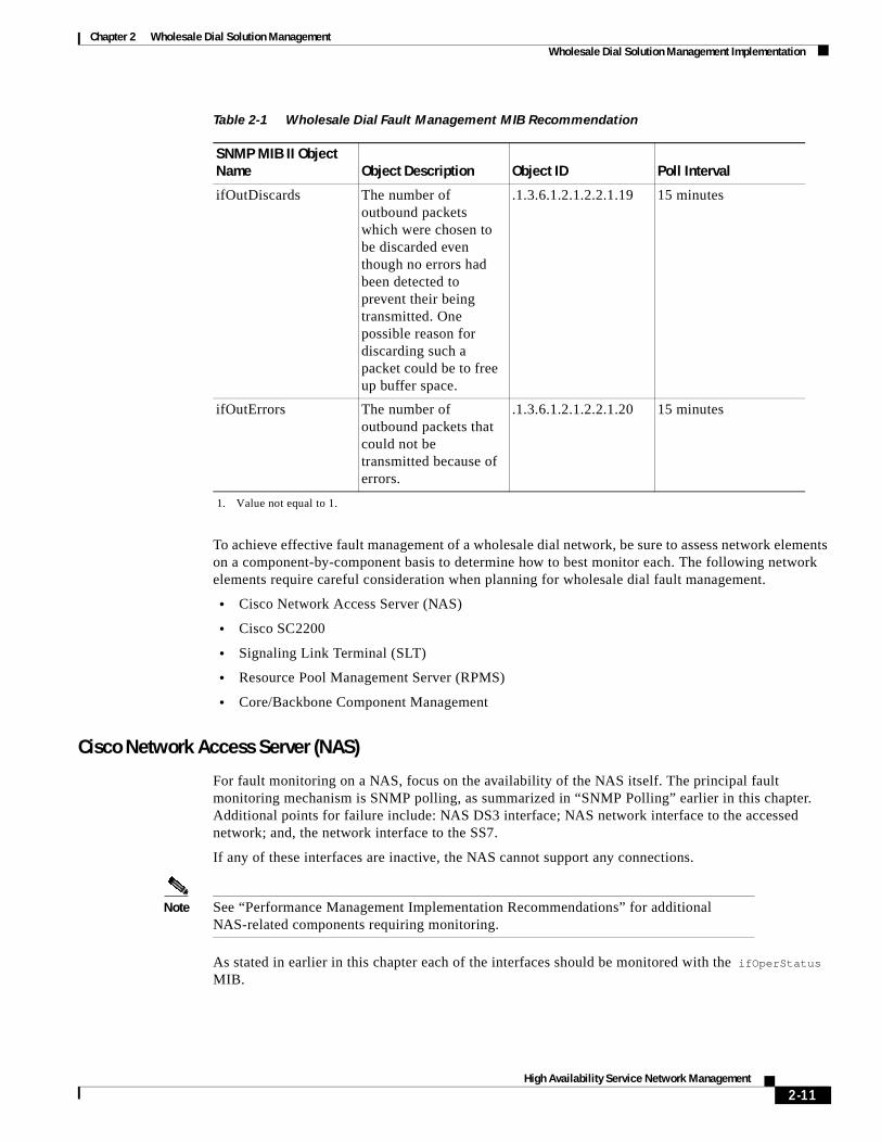
Because of the limited number on interfaces to monitor in a wholesale dial network, a few basic MIBs can be used to monitor all wholesale dial components for faults. Table 2-1 summarizes a specific MIB II object that can provide relevant status information.
2-9High Availability Service Network Management

Chapter 2 Wholesale Dial Solution ManagementWholesale Dial Solution Management Implementation
Table 2-1 Wholesale Dial Fault Management MIB Recommendation
SNMP MIB II Object Name Object Description Object ID Poll Interval
ifAdminStatus The desired state of the interface. The testing(3) state indicates that no operational packets can be passed.
.1.3.6.1.2.1.2.2.1.7 5 minutes
ifOperStatus The current operational state of the interface. The testing(3) state indicates that no operational packets can be passed.
.1.3.6.1.2.1.2.2.8 5 minutes1
ifInDiscards The number of inbound packets which were chosen to be discarded even though no errors had been detected to prevent their being deliverable to a higher-layer protocol. One possible reason for discarding such a packet could be to free up buffer space.
.1.3.6.1.2.1.2.2.1.13 15 minutes
ifInErrors The number of inbound packets that contained errors preventing them from being deliverable to a higher-layer protocol.
.1.3.6.1.2.1.2.2.1.14 15 minutes
2-10High Availability Service Network Management
Chapter 2 Wholesale Dial Solution ManagementWholesale Dial Solution Management Implementation
To achieve effective fault management of a wholesale dial network, be sure to assess network elements on a component-by-component basis to determine how to best monitor each. The following network elements require careful consideration when planning for wholesale dial fault management.
• Cisco Network Access Server (NAS)
• Cisco SC2200
• Signaling Link Terminal (SLT)
• Resource Pool Management Server (RPMS)
• Core/Backbone Component Management
Cisco Network Access Server (NAS)
For fault monitoring on a NAS, focus on the availability of the NAS itself. The principal fault monitoring mechanism is SNMP polling, as summarized in “SNMP Polling” earlier in this chapter. Additional points for failure include: NAS DS3 interface; NAS network interface to the accessed network; and, the network interface to the SS7.
If any of these interfaces are inactive, the NAS cannot support any connections.
Note See “Performance Management Implementation Recommendations” for additional NAS-related components requiring monitoring.
As stated in earlier in this chapter each of the interfaces should be monitored with the ifOperStatus MIB.
ifOutDiscards The number of outbound packets which were chosen to be discarded even though no errors had been detected to prevent their being transmitted. One possible reason for discarding such a packet could be to free up buffer space.
.1.3.6.1.2.1.2.2.1.19 15 minutes
ifOutErrors The number of outbound packets that could not be transmitted because of errors.
.1.3.6.1.2.1.2.2.1.20 15 minutes
1. Value not equal to 1.
Table 2-1 Wholesale Dial Fault Management MIB Recommendation
SNMP MIB II Object Name Object Description Object ID Poll Interval
2-11High Availability Service Network Management
Chapter 2 Wholesale Dial Solution ManagementWholesale Dial Solution Management Implementation
This is done automatically if you purchase a node manager product (such as HP OpenView). Using the OID directly only occurs if you manually set up polling. Manual configuration of polling might be required if you need more detailed polling, or if you are creating your own application.
Cisco SC2200
The SC2200 connects directly to the telephone network. The NAS receives signalling for its DS3 through the SC2200. For the SC2200, monitor:
• Availability of the SC2200
• Status of the F link coming from the Packet Switch Telephone Network (PSTN)
• Daemons on the SC2200 for proper operation
• Ethernet interface connecting the SC2000 to the Signaling Link Terminal (SLT)
Signaling Link Terminal (SLT)
The SLT is a card that is installed in a Cisco 3600 chassis. For the SLT, only the up/down (active/inactive) status of the interface can be monitored. No statistical information can be obtained from the SLT. Statistical information must be gathered from the SC2200.
Resource Pool Management Server (RPMS)
The Resource Pool Management Server (RPMS) is a software package running on a Sun Microsystems server. For RPMS, monitor:
• Availability of the system itself
• Daemons running on the system
• Ethernet interface connecting the RPMS server to the network
Note The RPMS server is an excellent source of accounting data, because every call must be authorized by the RPMS in a wholesale dial network. See “Accounting Management Implementation” for more information.
Core/Backbone Component Management
There are supporting components on a wholesale dial network that interconnect all of the components of the network (such as high-end routers and switches within the Telco’s core network fabric). For the most part these devices can be monitored as if they were LAN/WAN components. It is extremely critical to the wholesale dial network that these components work properly, but the specifics of ensuring proper functioning are beyond the scope of this document.
2-12High Availability Service Network Management

Chapter 2 Wholesale Dial Solution ManagementWholesale Dial Solution Management Implementation
Configuration Management ImplementationConfiguration management for a wholesale dial network is similar to any other type of network. The principals are the same. Configuration management deals with the configuration of devices (how the devices are setup to run), software management, and inventory management. Inventory management can be broken down into two components: what devices reside in the network; and, what components reside in the devices.
CiscoWorks 2000 Cisco Resource Manager Essentials (CRME) provides tools supporting configuration management of a wholesale dial network for both the network devices and embedded components. CRME is an element manager for Cisco switches, routers, and NASs.
Note An element manager is a software package that manages a specific category of devices in a network. Element managers usually are created by each vendor for its specific products. Element manager can manage an entire vendor product line; however, an element manager might also manage specific types of devices such as switches, routers, or access servers.
CRME is comprised of a set of tools presented collectively in a single web-based user interface. Some capabilities of CRME include the following:
• CRME provides inventory information, such as a list of all devices that can be separated into a product group. CRME also provides a detailed component inventory for each Cisco device. This information includes memory information and Cisco IOS image information. CRME displays this information in charts and graphs.
• CRME provides a tool for downloading, archiving, and viewing device configurations. CRME can also compare the device’s latest saved configuration to any other archived configuration from the same device. It can then display the differences if any exist. Configuration archiving can be scheduled so that saved configurations are never more than a few days old.
• CRME software image management (SWIM) provides a tool for managing software image changes. CRME allows a network administrator the ability maintain a software image library. This feature allows the administrator to schedule an image change when a device needs a different software version.
To configure the SC2000, use the Cisco Media Gateway Controller Manager (CMM) tool. The CMM has a graphical user interface (GUI) that uses SNMP to configure and provision your Cisco SC2200. CMM provides all the necessary tools for configuration management of the SC2200.
Additional information about CMM can be found at the following Cisco Connection Online web pages:
• http://www.cisco.com/univercd/cc/td/doc/product/access/sc/solution/sbcvpop/sbcdas.htm
• http://www.cisco.com/univercd/cc/td/doc/product/access/sc/rel7/cmnmgr/rambprod.htm
Accounting Management ImplementationAccounting management is the most complex component of the FCAPS model to effectively implement. Accounting in a wholesale dial network usually concerns tracking end user connections. For example, network managers might want to know which users have called in, how long they remain connected, and to which ISP they belong.
2-13High Availability Service Network Management

Chapter 2 Wholesale Dial Solution ManagementWholesale Dial Solution Management Implementation
The information needed to build accounting records are available in several locations. The modem call terse record is a SYSLOG message that is generated at the termination of every dial connection. The modem call terse record provides useful information that can help create trending analysis, and can help in troubleshooting specific connection problems. However, the modem call terse record is generated at the time of a call termination and cannot provide any information on active calls.
Another good source for collecting call information are the Remote Authentication Dial-in User Service (RADIUS) call records. These are generated at call generation. They are more difficult to capture, but provide information on active calls.
For generalized call accounting data, the RPMS server is an effective repository for these records. RPMS gives retail providers various statistics, such as:
• The number of end users dialed in at a specific time.
• The percentage of allocated resources used by a retailer.
RPMS also provides information indicating that a retailer has reached its resource limit and has started to reject calls by providing a call reject counter.
The application of RPMS statistics in this instance illustrates how the lines between FCAPS functions can be blurred, given that these same RPMS-derived statistics can be categorized with performance statistics.
For the purposes of this document, these statistics are included with accounting statistics because of the way that the statistics can be used. Consider a situation in which every retailer connected to a wholesale dial environment reaches its allocated capacity, although the wholesale dial network itself is easily within its total capacity constraint. In this instance, the RPMS call statistics are in effect accounting data—not performance data.
The subject of accounting in a dial network can easily generate several documents. Detailed information on dial accounting is beyond the scope of this document.
Performance Management Implementation RecommendationsAs stated earlier in this chapter, performance management is concerned with the measurement and analysis of both short-term and long-term network and system statistics related to:
• Utilization
• Response time
• Availability
• Error rates
Performance management in a wholesale dial network is relatively uncomplicated, with the exception of modem performance management. It can be split into two categories:
• Performance of the support network and network infrastructure itself
• Performance of connections
The performance management descriptions that follow are divided into the following sections:
• Monitoring Network Infrastructure Performance
• Monitoring Modem Performance
• Monitoring Call Performance
• Monitoring SC2200 Performance
• Availability Management Implementation
2-14High Availability Service Network Management

Chapter 2 Wholesale Dial Solution ManagementWholesale Dial Solution Management Implementation
Monitoring Network Infrastructure Performance
The performance management discussion here focuses on the performance management capabilities of individual NASs, not the network in aggregate. Three NAS interfaces require performance monitoring:
• DS3/T1 Interface
• Interface to the Network
• Ethernet Interface to the SLT Interface
For network performance monitoring, use a tool such as Concord’s Network Health. Network Health is specifically designed to monitor network performance. Network Health allows operators to view network, device, and segment statistics in a web-based format. Concord’s Network Health can also send a trap to a fault management application if a specific event is detected (such as a threshold being exceeded).
DS3/T1 Interface
Because of the intermittent nature of a dial-based connectivity, DS3 or T1 interface throughput is rarely an issue. The reason is that each call is limited to 64Kb per channel. As a result, there is never a large amount of data saturating a DS3 or T1 link.
The statistics graphed in Figure 2-3 and Figure 2-4 illustrate the total number of calls connected during a single day (Figure 2-3) and over a one week interval (Figure 2-4). To determine the capacity of a NAS, first determine the number of channels available for accepting calls, then determine the number of modems in the chassis. The lesser of these two is the total number of calls that can be accepted by this NAS.
Figure 2-3 Example DS0 Point-to-Point Protocol (PPP) Network Connections Graph (Single Day)
Figure 2-4 Example DS0 PPP Network Connections Graph (Week)
Determining the utilization of a point-of-presence (POP) is a little more difficult, because there are usually multiple NASs per POP. To create a single graph for a POP, first determine the capacity of each NAS, sum those, and then assemble a cumulative graph of all NASs.
2-15High Availability Service Network Management

Chapter 2 Wholesale Dial Solution ManagementWholesale Dial Solution Management Implementation
With dial traffic, you can typically expect approximately 80 percent idle time on a dial port. This results in relatively low total throughput from a NAS to the supporting network. Figure 2-5 illustrates how statistical graphing can help characterize the traffic behavior of a dial network.
Figure 2-5 Example Network Traffic Graph Illustrating Dial Connections for NAS
Figure 2-5 depicts a dial network featuring a 5:1 ratio of bytes received (downstream) in comparison to bytes sent (upstream). This suggests that the modem users receive five times as much data as they send on a dial network.
Some background on the graphic in Figure 2-5—The NAS graphed in Figure 2-5 has a DS3 link—for a total of 672 available channels. The all time peak for this NAS is five percent utilization of the Ethernet port that connects this NAS to the supporting network. The average is less than three percent.
Note Twelve T1/E1 lines can be used on the AS5800 instead of a DS3 link. However, T1/E1 lines are rarely implemented in a wholesale dial network. DS3 lines are more commonly used due to their ability to efficiently handle large numbers of simultaneous connections.
Interface to the Network
The interface that connects the NAS to the network also experiences a low utilization rate. If high utilization rates are registered, the likely causes are problems that are not related to the number of dial users or connections. However it is a good practice to monitor this interface for general performance statistics (such as utilization, collisions, and CRC errors).
Table 2-2 lists MIB objects that can be used to monitor overall connection activity.
Look for utilization rates of 10 percent or less on a 100Mb Ethernet interface, with an occasional spike. This interface also should be connected to a switch, so you should see 0 collisions, 0 CRC errors, and 0 retransmissions. If any of these metrics are being exceeded, a problem in the network exists that warrants additional diagnostic assessment.
Table 2-2 MIBs Suggested for Monitoring Dial Connections
MIB Object Name Object Description Object ID Poll Interval
cpuActive Displays the number of current dial connections
.1.3.6.1.4.1.9.10.19.1.1.4.0
5 minutes
cpmPPPCalls Displays the number of current PPP connections
.1.3.6.1.4.1.9.10.19.1.1.5.0
5 minutes
2-16High Availability Service Network Management

Chapter 2 Wholesale Dial Solution ManagementWholesale Dial Solution Management Implementation
Ethernet Interface to the SLT Interface
The SLT cannot be managed directly. The only information you can get from the SLT is standard MIB II information. All statistical information must be polled through the SC2200.
Monitoring Modem Performance
Monitoring modem performance is difficult in a dial network because it is impractical to poll performance statistics for every group of modems used for general network access. The performance of a set of modems largely depends on how often they are called, the type of modem calling, how long the call lasts, and how much data is sent through the connection.
Setting Up a Generic Dialer Tool
For true modem performance statistics, a modem with a known protocol such as V.90 calling through the PSTN connecting to the NAS for a specific amount of time, transmitting a specific amount of traffic is the only way to obtain accurate and meaningful performance statistics.
Currently, no commercial tool exists to do this; however, one can easily be built using a UNIX box and a PPP daemon such as pppd. To set up a generic dialer tool on a UNIX workstation, example steps are as follows:
Step 1 Connect a modem to the serial port.
Step 2 Write a script that initiates the call to a DNIS for a specific amount of time (such as 15 minutes). During that time the script specifies that the workstation transmits a specific amount of data. An example would be for the script to specify that the workstation send a file via the file transfer protocol (FTP) to another workstation attached to the same network.
Step 3 The modem call terse records can then be examined to determine which ports the modem tool connected to and if any problems were encountered during the call process.
Look for these problems:
• Premature disconnect
• Bad PPP negotiation
• Unacceptable signal to noise ratio
• Low connect speeds
Monitoring Call Performance
For the purposes of this document, monitoring call performance focuses on the total number of calls a wholesale dial infrastructure can handle and how efficiently the wholesale dial provider connects calls for the retailer. This includes how calls are rerouted if a POP becomes saturated.
RPMS tracks call resources. The RPMS server is used to allocate a pre-determined number of ports to a specific customer (ISP/retailer) in order to complete calls. RPMS tracks associated statistics both on a per ISP basis and in aggregate.
Note Remote monitoring using RPMS is facilitated by its web-based interface.
2-17High Availability Service Network Management

Chapter 2 Wholesale Dial Solution ManagementWholesale Dial Solution Management Implementation
Monitoring SC2200 Performance
SC2200 performance can be monitored through its element management tool—the Cisco CMM. It can also be monitored by a third party tool such as Concord Network Health.
The useful statistics to monitor on an SC2200 are as follows:
• Number of active calls
• Number or redirects
• Number of rejected calls
• Number of busy calls
Note The MIBs associated with these statistics are SNMP manageable.
In addition, important system data points to monitor include:
• CPU utilization
• SWAP
• Interface statistics
Refer to the following site for related MIB information:
• http://www.sun.com/software/sunmanagementcenter
Availability Management Implementation
Availability management can be split into three subtopics:
• Monitoring Device Availability
• Monitoring Path Availability
• Monitoring Service Availability
Note Because of the limited number on interfaces to monitor in a wholesale dial network, a few basic SNMP MIBs can be used to monitor all the wholesale dial components for faults. For related information, see Table 2-1 in “Fault Management for Wholesale Dial Components.”
Monitoring Device Availability
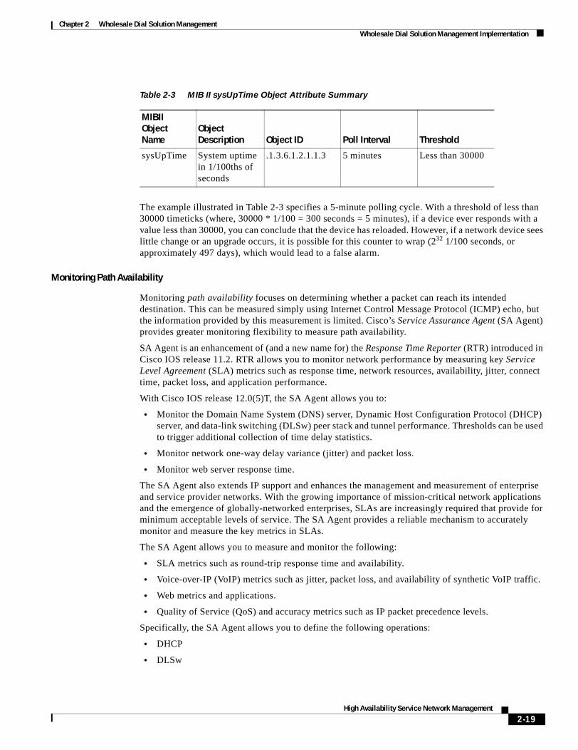
Monitoring device availability involves determining whether a device responding to ICMP echos and SNMP requests. Many applications can measure device availability, including Concord Network Health, Cisco Resource Manager Essentials (CRME), and Veritas’ NerveCenter. Depending on the SNMP request or ICMP echo intervals, it is possible for a device to reload (reboot). If the ColdStart SNMP trap is not received by the SNMP Manager, an operations center may never know that a device has reloaded. One way determine whether a reboot has occurred is to generate an SNMP request of the sysUpTime object. Table 2-3 illustrates example attributes for sysUpTime.
2-18High Availability Service Network Management
Chapter 2 Wholesale Dial Solution ManagementWholesale Dial Solution Management Implementation
The example illustrated in Table 2-3 specifies a 5-minute polling cycle. With a threshold of less than 30000 timeticks (where, 30000 * 1/100 = 300 seconds = 5 minutes), if a device ever responds with a value less than 30000, you can conclude that the device has reloaded. However, if a network device sees little change or an upgrade occurs, it is possible for this counter to wrap (232 1/100 seconds, or approximately 497 days), which would lead to a false alarm.
Monitoring Path Availability
Monitoring path availability focuses on determining whether a packet can reach its intended destination. This can be measured simply using Internet Control Message Protocol (ICMP) echo, but the information provided by this measurement is limited. Cisco’s Service Assurance Agent (SA Agent) provides greater monitoring flexibility to measure path availability.
SA Agent is an enhancement of (and a new name for) the Response Time Reporter (RTR) introduced in Cisco IOS release 11.2. RTR allows you to monitor network performance by measuring key Service Level Agreement (SLA) metrics such as response time, network resources, availability, jitter, connect time, packet loss, and application performance.
With Cisco IOS release 12.0(5)T, the SA Agent allows you to:
• Monitor the Domain Name System (DNS) server, Dynamic Host Configuration Protocol (DHCP) server, and data-link switching (DLSw) peer stack and tunnel performance. Thresholds can be used to trigger additional collection of time delay statistics.
• Monitor network one-way delay variance (jitter) and packet loss.
• Monitor web server response time.
The SA Agent also extends IP support and enhances the management and measurement of enterprise and service provider networks. With the growing importance of mission-critical network applications and the emergence of globally-networked enterprises, SLAs are increasingly required that provide for minimum acceptable levels of service. The SA Agent provides a reliable mechanism to accurately monitor and measure the key metrics in SLAs.
The SA Agent allows you to measure and monitor the following:
• SLA metrics such as round-trip response time and availability.
• Voice-over-IP (VoIP) metrics such as jitter, packet loss, and availability of synthetic VoIP traffic.
• Web metrics and applications.
• Quality of Service (QoS) and accuracy metrics such as IP packet precedence levels.
Specifically, the SA Agent allows you to define the following operations:
• DHCP
• DLSw
Table 2-3 MIB II sysUpTime Object Attribute Summary
MIBII Object Name
Object Description Object ID Poll Interval Threshold
sysUpTime System uptime in 1/100ths of seconds
.1.3.6.1.2.1.1.3 5 minutes Less than 30000
2-19High Availability Service Network Management

Chapter 2 Wholesale Dial Solution ManagementWholesale Dial Solution Management Implementation
• DNS
• Hypertext Transfer Protocol (HTTP)
• Jitter
SA Agent can be configured via the Cisco IOS command line interface (CLI), SNMP (via the RTTMON MIB), or through applications such as Cisco’s Internetwork Performance Monitor (IPM) or Cisco’s Service Management Solution (SMS), consisting of Cisco Service Level Manager and the ME1100 Management Engines. Cisco IPM and Cisco SMS also can act as data collectors as well as provide data archiving and reporting.
Regardless of how you deploy SA Agent in the network environment, you can configure SA Agent to send a SNMP trap to your SNMP manager when a configured threshold is exceeded. This presents the possibility of alerting your Network Operations Center (NOC) to specific path failures and performance degradation issues.
For more information, please refer to the following documents:
• Cisco SA Agent: http://www.cisco.com/univercd/cc/td/doc/product/software/ios120/120newft/120t/120t5/saaoper.htm
• Cisco IPM: http://www.cisco.com/warp/public/cc/pd/wr2k/nemo/prodlit/ipm2_ov.htm
• Cisco SMS: http://www.cisco.com/warp/public/cc/pd/wr2k/svmnso/prodlit/sms_ov.htm
Monitoring Service Availability
Selecting a tool for monitoring service availability depends on the service being measured. Cisco SA Agent provides metrics for key network services such as DHCP, DNS, and HTTP requests. To measure application availability and response, Concord provides various add-on modules to the Network Health core application. Other vendors provide applications for measuring specific application availability and performance.
Security Management ImplementationSecurity management in this document focuses on authentication, authorization, and accounting (AAA) management for dial access to ports and access to devices. To fully address the issue of security management, you must consider the complete range of network access security issues—including firewall, server security, and device security. These topics are beyond the scope of this document.
A wholesale dial provider cannot realistically keep up with access requests from customers/retailers (ISPs and other dial retailers). The best way to deal with this issue is to require each ISP to maintain its own AAA server. For dial access, that usually involves a RADIUS-based AAA server solution.
In addition to the basic dial connectivity security provided by a AAA server environment, it is also good practice to control and monitor access to network devices themselves (such as NASs and routers). To control and monitor access to the network devices, implement a AAA server using Access Registrar software. This Access Registrar-based AAA server should be a separate entity (not an integral function of any other dial access servers). Access Registrar software is based on the AAA model of network security and it incorporates both Terminal Access Controller Access Control System Plus (TACACS+) and RADIUS protocols. By using AAA you can monitor and track individuals accessing network devices.
For more information about AAA implementation, refer to following document:
• http://www.cisco.com/univercd/cc/td/doc/cisintwk/intsolns/aaaisg/index.htm
2-20High Availability Service Network Management

Chapter 2 Wholesale Dial Solution ManagementWholesale Dial Solution Management Implementation
2-21High Availability Service Network Management

Chapter 2 Wholesale Dial Solution ManagementWholesale Dial Solution Management Implementation
2-22High Availability Service Network Management

High Availab
C H A P T E R 3
Wholesale Dial NMS Case StudyThe chapter presents a case study illustrating a network management system designed to meet the requirements of a wholesale dial network. The design presented here uses components intended to ensure that each element of the FCAPS model is addressed. In addition, the NMS implementation featured in this case study addresses the requirement for a high level of redundancy and availability.
This case study illustrates the application of several popular industry NMS software packages as well as Cisco element management systems. These tools combine to provide a complete NMS architecture. When managing large networks (as in this case study), it can be advantageous to construct a distributed NMS solution—instead of a centralized solution. Distributing functions allows SNMP polling to be more local to each managed device, spreads system resources (thereby reducing the threat of system overload), and makes the overall NMS environment more resilient.
The remainder of this chapter consists of the following sections:
• The Wholesale Dial NMS Architecture
• Applying the FCAPS Model
• Server Recommendations and Configurations
• System Fail-over / Backup Configuration for Collection Stations
The Wholesale Dial NMS ArchitectureThis case study presents a wholesale dial NMS environment in the context of the following key elements:
• Management Stations and Collection Stations
• Distributed Network Management Systems
The sections that following summarize each of these elements and general considerations for managing a wholesale dial environment.
Management Stations and Collection StationsA distributed NMS environment consists of two basic systems:
• Management Station (MS)—A management station relies on the collection station to manage a specific group of nodes. This group of nodes is called a management domain (MD). A management station provides an end-to-end view of the network status.
3-1ility Service Network Management

Chapter 3 Wholesale Dial NMS Case StudyThe Wholesale Dial NMS Architecture
• Collection Station (CS)—A collection station monitors its portion of the network and relays the status to its management station. The collection station performs status monitoring, event handling (traps), and health checking.
Each management station shares its information with the other management stations, providing a complete view of the wholesale dial network.
Note A management station can also be a collection station depending how the architecture is designed. However, the details of such design considerations are beyond the scope of this document.
A management station receives information from collection stations that are actively receiving traps and performing status polling.
Based on the network design, each collection station is responsible for managing a set of access servers and support equipment. The number of access servers and support equipment associated with a collection station generally should not exceed 600 devices, but can based upon the resources of the collection station. The hierarchical placement of a collection station’s associated management station can be based on geographical region or organizational lines. For this case study, the hierarchy of management stations is organized based on geographical location. If you need to add another set of managed devices, the only change necessary is the addition of another collection station in order to extend the NMS.
Distributed Network Management SystemsThe fault management system design presented in this case study is based on HP OpenView's Network Node Manager (NNM) Distributed Internet Discovery and Monitoring (DIDM) model. The DIDM model is the mechanism for providing a redundant distributed NMS architecture. Using the DIDM model, helps form a conceptual foundation for integrating the rest of the NMS components.
Figure 3-1 illustrates an example HP OpenView-based NMS environment featuring a redundant management scheme supporting multiple management domains. The section that follows (“Applying the FCAPS Model”) explores how this environment can be used to implement an FCAPS-based network management system.
CiscoWorks 2000 (CW2000) is used for configuration management in this case study. In this environment, each management station runs CW2000. This gives each Network Operation Center (NOC) the ability to perform configuration management tasks. CW2000 provides configuration and inventory management for Cisco NASs, switches, and routers.
The configuration and maintenance of the SC2200 is handled by Cisco Media Gateway Controller Manager (CMM). CMM is an element management system designed specifically for the SC2200. CMM handles all the configuring and provisioning the SC2200s in the network. CMM also can reside on the management station platforms—permitting each NOC to perform configuration management on SC2200s.
3-2High Availability Service Network Management

Chapter 3 Wholesale Dial NMS Case StudyApplying the FCAPS Model
Figure 3-1 Overview of Example NMS Case Study Environment
Applying the FCAPS ModelIn the context of a wholesale dial environment, the HP OpenView DIDM model and the OSI NMS FCAPS model can be applied to the following network management areas:
• Fault and Configuration Management
• Event Management
• Performance Management
• Security Integration
Fault and Configuration ManagementThe DIDM model allows for more than one NOC to have a fully operational fault management system (as illustrated in Figure 3-1). This allows for the network to be separated into multiple management domains—each monitored by its own fault manager. Thus, two primary management domains exist in this solution. Each fault manager shares real-time information with the other fault manager. Furthermore, each of the management domains has a sub-domain, containing a Veritas NerveCenter. This distributed approach promotes scalability and reduces traffic caused by polling because it pushes polling closer to the managed devices.
5001
1
Managementdomain
A
Managementdomain
B
ConcordNetwork
Health
ConcordNetworkHealth
HPOVNNM/CW2000
Cisco Info Center
HPOVNNM/CW2000
Managementdomain
C
Managementdomain
D
ManagementStations
(NNM/CW2000/CMM)
CollectionStations(NerveCenter)
3-3High Availability Service Network Management

Chapter 3 Wholesale Dial NMS Case StudyApplying the FCAPS Model
Note This environment could have implemented HP OpenView for collection stations; however, NerveCenter was selected because of its support of event correlation, trap filtering, and its flexible polling engine.
An enterprise-class UNIX server should be deployed for each fault management system. This facilitates growth while allowing for some element managers to be co-located on these servers. A Sun E4000 server would support a medium to large network. HPOV Network Node Manager Version 6.0 resides on this system, along with CiscoWorks 2000. The E4000 class server is powerful enough to handle the fault and configuration management load for the entire wholesale dial network if one of the servers fails.
Note For related information in the document about element managers, see the “Configuration Management Implementation” section on page 2-13.
Event ManagementEvent management systems provide mechanisms that automate actions to resolve issues, email/pager notifications, and create trouble tickets. The Cisco Info Center (CIC) supports these functions. A CIC system can reside at the same location as a HPOV NNM system. While the CIC in this case would reside at one of the NOCs and would be associated with one of the HPOV NNM management stations, both management stations would have the same level of access. Figure 3-1 illustrates the CIC as situated logically above both management stations. A CIC trapd converter is loaded on the HPOV server, allowing SNMP on HPOV NNM to be converted and sent to the CIC.
Performance ManagementIn selecting and implementing a performance management system, first consider the usability of the application, followed by scalability and reliability. Based on these concerns, this case study calls for the implementation of Concord’s Network Health.
Network Health is a web-based performance management tool that provides predefined graphs and graphing templates. Network Health can be deployed in a distributed architecture, in very much the same manner that HPOV NNM is deployed in this case study.
For this case study we use a SUN Microsystems 420R containing Concord’s Network Health with one located in each NOC and splitting the wholesale dial network into two performance management domains. Each Concord Network Health shares information with its peers so that each NOC has a complete view of the network as it relates to performance.
Security IntegrationAccess Registrar is implemented for access security in this case study. Access Registrar’s configuration consists of two servers strategically placed in the network. Each server includes an underlying Oracle database. The databases are mirrored to allow the Access Registrar servers to share AAA information. This approach provides a backup system if one server is unavailable and distributes the AAA load.
Access Registrar does not integrate with other elements of the NMS solution, except that it should be configured to send a server daemon status to CIC, alerting the network operator of server problems.
3-4High Availability Service Network Management
Chapter 3 Wholesale Dial NMS Case StudyServer Recommendations and Configurations
The wholesale dial service provider should implement its own access server for staff accounts and maintenance accounts. However, each retailer (ISP) should be responsible for its own account security. This administrative separation insulates the wholesale dial provider from supporting individual dial users.
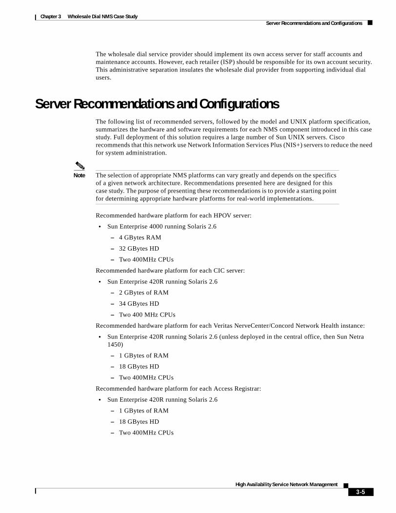
Server Recommendations and ConfigurationsThe following list of recommended servers, followed by the model and UNIX platform specification, summarizes the hardware and software requirements for each NMS component introduced in this case study. Full deployment of this solution requires a large number of Sun UNIX servers. Cisco recommends that this network use Network Information Services Plus (NIS+) servers to reduce the need for system administration.
Note The selection of appropriate NMS platforms can vary greatly and depends on the specifics of a given network architecture. Recommendations presented here are designed for this case study. The purpose of presenting these recommendations is to provide a starting point for determining appropriate hardware platforms for real-world implementations.
Recommended hardware platform for each HPOV server:
• Sun Enterprise 4000 running Solaris 2.6
– 4 GBytes RAM
– 32 GBytes HD
– Two 400MHz CPUs
Recommended hardware platform for each CIC server:
• Sun Enterprise 420R running Solaris 2.6
– 2 GBytes of RAM
– 34 GBytes HD
– Two 400 MHz CPUs
Recommended hardware platform for each Veritas NerveCenter/Concord Network Health instance:
• Sun Enterprise 420R running Solaris 2.6 (unless deployed in the central office, then Sun Netra 1450)
– 1 GBytes of RAM
– 18 GBytes HD
– Two 400MHz CPUs
Recommended hardware platform for each Access Registrar:
• Sun Enterprise 420R running Solaris 2.6
– 1 GBytes of RAM
– 18 GBytes HD
– Two 400MHz CPUs
3-5High Availability Service Network Management
Chapter 3 Wholesale Dial NMS Case StudySystem Fail-over / Backup Configuration for Collection Stations
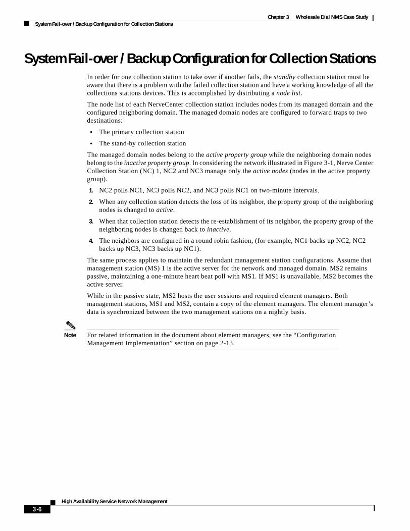
System Fail-over / Backup Configuration for Collection StationsIn order for one collection station to take over if another fails, the standby collection station must be aware that there is a problem with the failed collection station and have a working knowledge of all the collections stations devices. This is accomplished by distributing a node list.
The node list of each NerveCenter collection station includes nodes from its managed domain and the configured neighboring domain. The managed domain nodes are configured to forward traps to two destinations:
• The primary collection station
• The stand-by collection station
The managed domain nodes belong to the active property group while the neighboring domain nodes belong to the inactive property group. In considering the network illustrated in Figure 3-1, Nerve Center Collection Station (NC) 1, NC2 and NC3 manage only the active nodes (nodes in the active property group).
1. NC2 polls NC1, NC3 polls NC2, and NC3 polls NC1 on two-minute intervals.
2. When any collection station detects the loss of its neighbor, the property group of the neighboring nodes is changed to active.
3. When that collection station detects the re-establishment of its neighbor, the property group of the neighboring nodes is changed back to inactive.
4. The neighbors are configured in a round robin fashion, (for example, NC1 backs up NC2, NC2 backs up NC3, NC3 backs up NC1).
The same process applies to maintain the redundant management station configurations. Assume that management station (MS) 1 is the active server for the network and managed domain. MS2 remains passive, maintaining a one-minute heart beat poll with MS1. If MS1 is unavailable, MS2 becomes the active server.
While in the passive state, MS2 hosts the user sessions and required element managers. Both management stations, MS1 and MS2, contain a copy of the element managers. The element manager’s data is synchronized between the two management stations on a nightly basis.
Note For related information in the document about element managers, see the “Configuration Management Implementation” section on page 2-13.
3-6High Availability Service Network Management

High Availabi
A P P E N D I X A
Application RecommendationsTable A-1 summarizes is a list of devices that can be used to implement the wholesale dial NMS solution introduced in this document. Table A-1 illustrates how various recommended applications fit into the OSI NMS model.
Table A-1 Mapping of NMS Components with respect to FCAPS Function
Fault Configuration Accounting Performance Security
HPOV NNM *
NerveCenter *
CW2000 * * *
Cisco Info Center *
Cisco Media Gateway Controller Manager (CMM)
* * *
Cisco Secure *
Concord Net Health
*
RPMS *
A-1lity Services Network Management

Appendix A Application Recommendations
A-2High Availability Services Network Management

High Availabi
A P P E N D I X B
Wholesale Dial SNMP MIBsThis section describes the MIBs and OIDs used to manage the dial Internet access service in the case study. See the following tables and choose the variables you want to use in your network.
Caution Polling OIDs that retrieve large amounts of data can cause CPU problems on a Cisco IOS device. For example, do not retrieve the ARP table, walk large portions of a MIB tree, poll the wrong OID too frequently, or get statistics that have an entry for every interface.
Table B-1 lists key MIBs that apply to dial environments.
Additional information:
• For a complete list of available Cisco MIBs, go to http://www.cisco.com/public/sw-center/netmgmt/cmtk/mibs.shtml
• For a list of Cisco-supported traps, go to http://www.cisco.com/public/mibs/traps
• For more information about other NMS enhancements for dial, see Call Tracker plus ISDN and AAA Enhancements for the Cisco AS5300 and Cisco AS5800 at
http://www.cisco.com/univercd/cc/td/doc/product/software/ios121/121newft/121limit/121x/121xh/121xh_2/dt_cltrk.htm
Table B-1 MIBs to Consider Using for the Dial NMS
Dial Related System Management MIB II / Interfaces
CISCO-POP-MGMT-MIB1 OLD-CISCO-CHASSIS RFC1213-MIB
CISCO-MODEM-MGMT-MIB CISCO-MEMORY-POOL-MIB IF-MIB
CISCO-VPDN-MGMT-MIB CISCO-SYSTEM-MIB CISCO-CAS-IF-MIB
CISCO-AAA-SESSION-MIB CISCO-FLASH-MIB CISCO-ISDN-MIB
CISCO-AAA-SERVER-MIB CISCO-CONFIG-MAN-MIB
CISCO-CALL-HISTORY-MIB CISCO-PROCESS-MIB
CISCO-DIAL-CONTROL-MIB
CISCO-CALL-RESOURCE-POOL-MIB
1. This MIB was enhanced in Cisco IOS Release 12.1(2)XH and later releases.
B-1lity Services Network Management

Appendix B Wholesale Dial SNMP MIBs
Note To protect a network access server from over polling, use the SNMP get bulk feature. It’s available in SNMP v2 in CISCO-BULK-FILE-MIB.
Table B-2 and Table B-3 identify useful OIDs and variables within selected MIBs from Table B-1. Equivalent Cisco IOS commands are shown where applicable. Sometimes data is more clearly inspected by using OIDs and a graphing tool instead of CLI commands.
To see the complete structure of the CISCO-POP-MGMT-MIB and CISCO-MODEM-MGMT-MIB, go to the following URLs:
• CISCO-POP-MGMT-MIB
http://www.cisco.com/univercd/cc/td/doc/cisintwk/intsolns/dialnms/popmgt.txt
• CISCO-MODEM-MGMT-MIB
http://www.cisco.com/univercd/cc/td/doc/cisintwk/intsolns/dialnms/modemmgt.txt
Table B-2 Description of CISCO-POP-MGMT-MIB
Description OIDEquivalent Cisco IOS Command
Number of analog calls connected cpmISDNCfgBChanInUseForAnalog
.1.3.6.1.4.1.9.10.19.1.1.2
show modem summary
Number of active DS0s in use cpmActiveDS0s
.1.3.6.1.4.1.9.10.19.1.1.4
show controllers t1 call-counters
show isdn memory (See the number of call control blocks, CCBs, in the command output.)
Total call count per DS0 cpmCallCount
.1.3.6.1.4.1.9.10.19.1.1.1.1.7
show controllers t1 call-counters
Total time in use for each DS0 cpmTimeInUse
.1.3.6.1.4.1.9.10.19.1.1.1.1.8
show controllers t1 call-counters
Total octets received on a DS0 cpmInOctets
.1.3.6.1.4.1.9.10.19.1.1.1.1.9
None available
Total octets transmitted on a DS0 cpmOutOctets
.1.3.6.1.4.1.9.10.19.1.1.1.1.10
None available
Total packets received on a DS0 cpmInPackets
.1.3.6.1.4.1.9.10.19.1.1.1.1.11
None available
Total packets transmitted on a DS0 cpmOutPackets
.1.3.6.1.4.1.9.10.19.1.1.1.1.12
None available
Number of active PPP calls cpmPPPCalls
.1.3.6.1.4.1.9.10.19.1.1.5
None available
Number of active V120 calls cpmV120Calls
.1.3.6.1.4.1.9.10.19.1.1.6
None available
B-2High Availability Services Network Management

Appendix B Wholesale Dial SNMP MIBs
Number of active V110 calls cpmV110Calls
.1.3.6.1.4.1.9.10.19.1.1.7
None available
Maximum number of DS0s used simultaneously
cpmActiveDS0sHighWaterMark
.1.3.6.1.4.1.9.10.19.1.1.8
show controllers t1 call-counters
Type of call currently connected to each DS0
cpmDS0CallType
.1.3.6.1.4.1.9.10.19.1.1.1.1.5
None available
Table B-2 Description of CISCO-POP-MGMT-MIB (continued)
Description OIDEquivalent Cisco IOS Command
Table B-3 Description of CISCO-MODEM-MGMT-MIB
Variable Description OIDEquivalent Cisco IOS Command
Modems available to take calls cmSystemModemsAvailable
.1.3.6.1.4.1.9.9.47.1.1.7
show modem summary
Average call duration for each modem
cmCallDuration
.1.3.6.1.4.1.9.9.47.1.3.1.1.9
show modem
Number of times each modem failed to answer
cmRingNoAnswers
.1.3.6.1.4.1.9.9.47.1.3.3.1.1
show modem
Number of times each modem failed to train up successfully
cmIncomingConnectionFailures
.1.3.6.1.4.1.9.9.47.1.3.3.1.2
show modem
Number of times each modem successfully trained up
cmIncomingConnectionCompletions
.1.3.6.1.4.1.9.9.47.1.3.3.1.3
show modem
Current TX speed for all the modems
cmTXRate
.1.3.6.1.4.1.9.9.47.1.3.1.1.14
show modem connect-speeds
Current RX speed for all the modems
cmRXRate
.1.3.6.1.4.1.9.9.47.1.3.1.1.15
show modem connect-speeds
List of users currently connected and authenticated
cpmActiveUserID
.1.3.6.1.4.1.9.10.19.1.3.1.1.3
show caller
Call durations for currently connected and authenticated users
cpmActiveCallDuration
.1.3.6.1.4.1.9.10.19.1.3.1.1.8
show caller
List of user CLIDs cpmActiveRemotePhoneNumber
.1.3.6.1.4.1.9.10.19.1.3.1.1.2
show caller ip
show isdn history
List of called DNIS phone numbers cpmActiveLocalPhoneNumber
.1.3.6.1.4.1.9.10.19.1.3.1.1.13
show caller ip
List of TTY interfaces in use cpmActiveTTYNumber
.1.3.6.1.4.1.9.10.19.1.3.1.1.14
show caller ip
B-3High Availability Services Network Management

Appendix B Wholesale Dial SNMP MIBsSNMP OIDs and MIBs
SNMP OIDs and MIBsSNMP uses Object Identifiers (OIDs) to represent managed system variables. OIDs must be known to the management station as well as the managed agent that resides on the managed device. A defined collection or group of OIDs makes up a Management Information Base (MIB). A MIB is generally grouped by its area of management. For example, Cisco’s CISCO-ISDN-MIB-V1SMI.my MIB provides objects or OIDs to manage ISDN connections.
The construction of SNMP OIDs and MIBs are defined in the SNMP Structure of Management Information (SMI). The SMI is defined in RFC 1155, RFC 1212, and RFC 1215. The SNMP SMI states that each managed object must have a name, a syntax, and an encoding. The name (corresponding to the OID) uniquely identifies the object. The syntax defines the type of data. The encoding defines how the data associated with the OID is serialized for transmission.
Note You can download Cisco SNMP MIBs from the following FTP server location: ftp://ftp.cisco.com/pub/mibs/
Each object’s unique OID is written as a sequences of integers separated by periods. For example, the numeric OID .1.3.6.1.2.1.1.5 corresponds to the OID name sysName. From an operational perspective, a management station sends a Get request with this (or some other) OID. The managed device receives the request and returns an appropriate response (in this case the host name of the device) back to the management station. If the managed device does not know the OID, it replies with no information.
OIDs are organized into a tree structure. For more information on this tree structure go to:
• http://www.cisco.com/univercd/cc/td/doc/cisintwk/ito_doc/snmp.htm
Within this tree structure, each level (or branch) of the tree is assigned a unique mnemonic name—down to the object itself. These names directly correspond to the OID. For example, using the sysName example, the OID .1.3.6.1.2.1.1.5 can be expressed as follows:
• .ios(1).org(3).dod(6).internet(1).mgmt(2).mib-2(1).system(1).sysName(5)
Each object is assigned a unique mnemonic name to simplify identification. This OID can be referred to as sysName, because no other object possesses the same name.
The leading point (or dot) at the beginning of an OID asserts that the name of the OID starts at the root of the respective MIB. With a Cisco MIB, the first integer is always the integer 1 and corresponds to ios. In some cases, an OID is written with the first few integers removed because these integers are the same for every OID; however, this document uses the full numeric OID, but refers its unique mnemonic name—such as sysName.
List of which user is using which modem slot
cpmActiveModemSlot
.1.3.6.1.4.1.9.10.19.1.3.1.1.6
show caller user
List of which user is using which modem port
cpmActiveModemPort
.1.3.6.1.4.1.9.10.19.1.3.1.1.7
show caller user
List of which IP addresses are currently in use
cpmActiveUserIpAddr
.1.3.6.1.4.1.9.10.19.1.3.1.1.4
show caller ip
Table B-3 Description of CISCO-MODEM-MGMT-MIB (continued)
Variable Description OIDEquivalent Cisco IOS Command
B-4High Availability Services Network Management

Appendix B Wholesale Dial SNMP MIBsSNMP OIDs and MIBs
B-5High Availability Services Network Management

Appendix B Wholesale Dial SNMP MIBsSNMP OIDs and MIBs
B-6High Availability Services Network Management

High Availabi
A P P E N D I X C
Suggested Reading and ReferencesInternational Organization for Standards, Information Processing Systems: Open System interconnection, Basic Reference Model, Part 4: Management Framework, ISO 7498-4-1989.
Miller, Mark A. Managing Internetworks with SNMP. IDG Books World Wide, 1999 ISBN 0-7645-7518-X.
Stallings, William. SNMP, SNMPv2, SNMPv3 and RMON1 and 2, 2nd Edition. Addison-Wesley, 1996: ISBN 0-201-48634-6
Harnedy, Sean. Total SNMP: Exploring the Simple Network Management Protocol, Second Edition. Prentice Hall PTR. 1998, ISBN 0-13-646994-9
Aidarous, Salah: Plevyak, Thomas: Telecommunications Network Management. IEEE Press, 1997 ISBN 0-7803-3454-X.
Raman, Lakshimi G.: "Fundamentals of Telecommunications Network Management" IEEE Press, 1999 ISBN 0-7803-3466-3
Jander, Mary. “Welcome to the Revolution,” Data Communications (November 21, 1996); pp 39-53.
C-1lity Services Network Management

Appendix C Suggested Reading and References
C-2High Availability Services Network Management