Embed Size (px)
Citation preview

High Temperature Superconductor g p pPower Applications
CERN Accelerator SchoolCERN Accelerator SchoolMay 1st 2013, Erice, Italy
Prof Dr -Ing Mathias Noe
M. Noe HTS Power Appllications, CERN Accelerator School , May 1st 2013, Erice, Italy
Prof. Dr. Ing. Mathias NoeInstitute for Technical Physics, Karlsruhe Institute of Technology, Germany
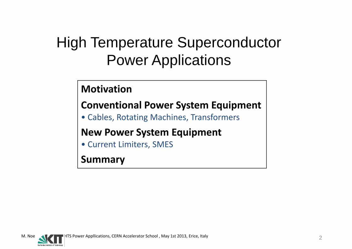
High Temperature Superconductor P A li tiPower Applications
MotivationConventional Power System Equipment• Cables, Rotating Machines, Transformers
New Power System Equipment• Current Limiters, SMES
Summary
M. Noe HTS Power Appllications, CERN Accelerator School , May 1st 2013, Erice, Italy 2

High Temperature Superconductor P A li tiPower Applications
MotivationConventional Power System Equipment• Cables, Rotating Machines, Transformers
New Power System Equipment• Current Limiters, SMES
Summary
Motivation and BenefitsDesign AspectsDesign AspectsState-of-the-Art
M. Noe HTS Power Appllications, CERN Accelerator School , May 1st 2013, Erice, Italy 3

Motivation
19. Century 20. Century 21. Century
Fossile Energy Carrier
Sustainable Energy
Coal and WaterEnergy Carrier Energy
What is the role of SuperconductivityWhat is the role of Superconductivityin this new energy age?
„Load and generation is locally coupled“
„Generation follows load“
„Load follows generation“
(Intelligent Systems)
The 21st century is a step into a new energy age
M. Noe HTS Power Appllications, CERN Accelerator School , May 1st 2013, Erice, Italy 4

MotivationThe Role of Superconductivity for Power ApplicationsThe Role of Superconductivity for Power Applications
SuperconductivitySuperconductivity Highest current densities at zero DC resistance and at high magnetic fields
I P A li iImpact on Power Applications
Improved energy efficiency
Application examples Loss reduction
Generators (some MVA) 30-40 %p gy y Generators (some MVA)Generators (> 100 MVA)
30 40 %40-50 %
Transformers stationary ~ 50 %Transformers mobile 80-90 %Magnetic heating ~ 50 %Magnetic separation > 80 %Magnetic separation > 80 %HTS currents leads 70-80 %HTS high field magnets > 90 %
M. Noe HTS Power Appllications, CERN Accelerator School , May 1st 2013, Erice, Italy 5
HTS high field magnets 90 %

MotivationThe Role of Superconductivity for Power ApplicationsThe Role of Superconductivity for Power Applications
SuperconductivitySuperconductivity Highest current densities at zero DC resistance and at high magnetic fields
I P A li iImpact on Power Applications
Improved energy efficiency Volume and weight reductionp gy y
Higher power density
Volume and weight reductionGenerators 30-50 %
Transformers 30-50 %
Cables > 50 %
M. Noe HTS Power Appllications, CERN Accelerator School , May 1st 2013, Erice, Italy 6
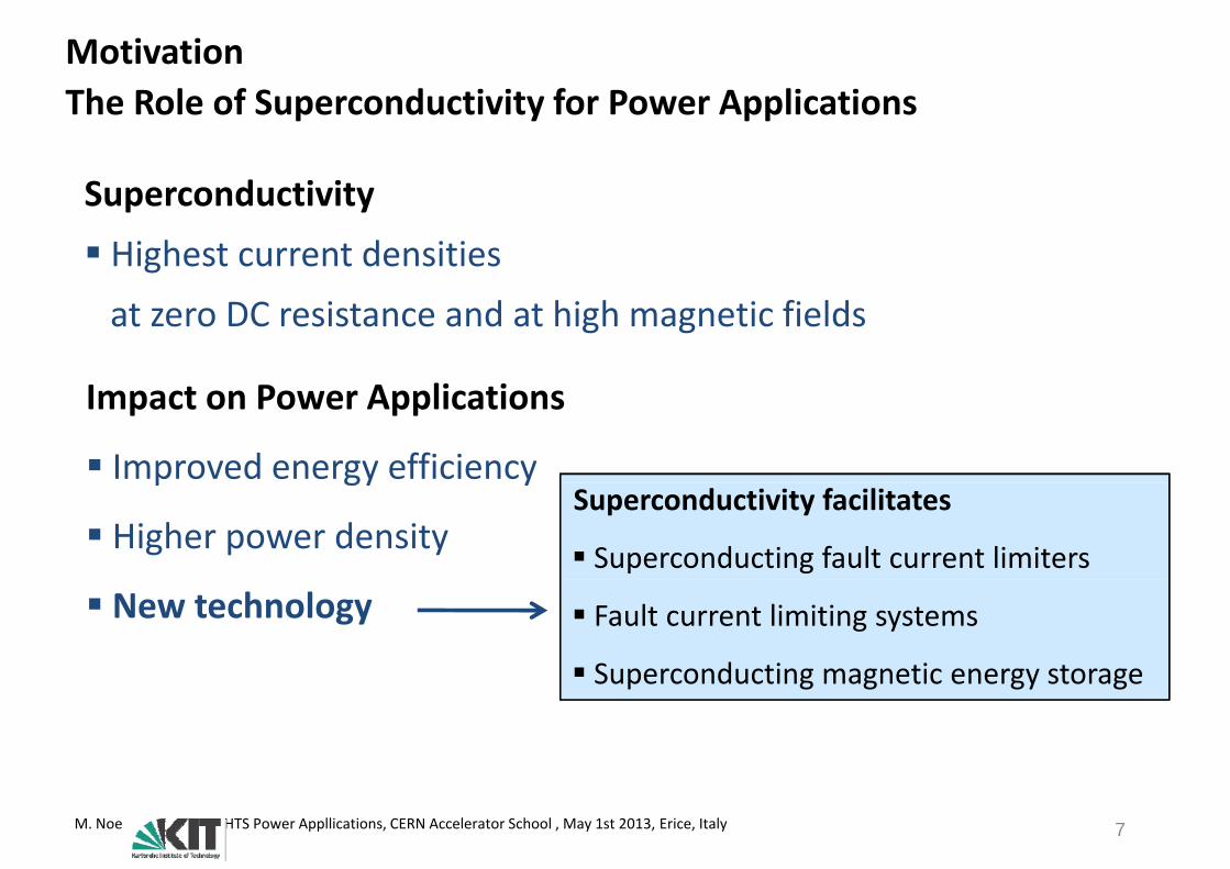
MotivationThe Role of Superconductivity for Power ApplicationsThe Role of Superconductivity for Power Applications
SuperconductivitySuperconductivity Highest current densities at zero DC resistance and at high magnetic fields
I P A li iImpact on Power Applications
Improved energy efficiencyp gy y
Higher power densitySuperconductivity facilitates
Superconducting fault current limiters New technology Fault current limiting systems
Superconducting magnetic energy storage Superconducting magnetic energy storage
M. Noe HTS Power Appllications, CERN Accelerator School , May 1st 2013, Erice, Italy 7

MotivationThe Role of Superconductivity for Power ApplicationsThe Role of Superconductivity for Power Applications
SuperconductivitySuperconductivity Highest current densities at zero DC resistance and at high magnetic fields
I P A li iImpact on Power Applications
Improved energy efficiencyp gy y
Higher power densityHigher power quality
Low impedance of superconducting power equipment
New technology
Higher power quality
equipment
High short-circuit capacity of grids with fault current limiters Higher power quality current limiters
Fast compensation of disturbances withsuperconducting magnetic energy storage
M. Noe HTS Power Appllications, CERN Accelerator School , May 1st 2013, Erice, Italy 8

MotivationThe Role of Superconductivity for Power ApplicationsThe Role of Superconductivity for Power Applications
SuperconductivitySuperconductivity Highest current densities at zero DC resistance and at high magnetic fields
I P A li iImpact on Power Applications
Improved energy efficiencyp gy y
Higher power densityLiquid Nitrogen
New technology
Higher power quality
Liquid Nitrogen
is used as cooling liquid and electricalinsulation Higher power quality
Environment‐friendly easily available
inflammable
M. Noe HTS Power Appllications, CERN Accelerator School , May 1st 2013, Erice, Italy 9
inflammable

MotivationThe Role of Superconductivity for Power ApplicationsThe Role of Superconductivity for Power Applications
SuperconductivitySuperconductivity Highest current densities at zero DC resistance and at high magnetic fields
I P A li iImpact on Power Applications
Improved energy efficiencyp gy y
Higher power density
New technology
Higher power quality Higher power quality
Environment‐friendly
M. Noe HTS Power Appllications, CERN Accelerator School , May 1st 2013, Erice, Italy 10
High Temperature Superconductor P A li tiPower Applications
MotivationConventional Power System Equipment• Cables, Rotating Machines, Transformers
New Power System Equipment• Current Limiters, SMES
Summary
M. Noe HTS Power Appllications, CERN Accelerator School , May 1st 2013, Erice, Italy 11
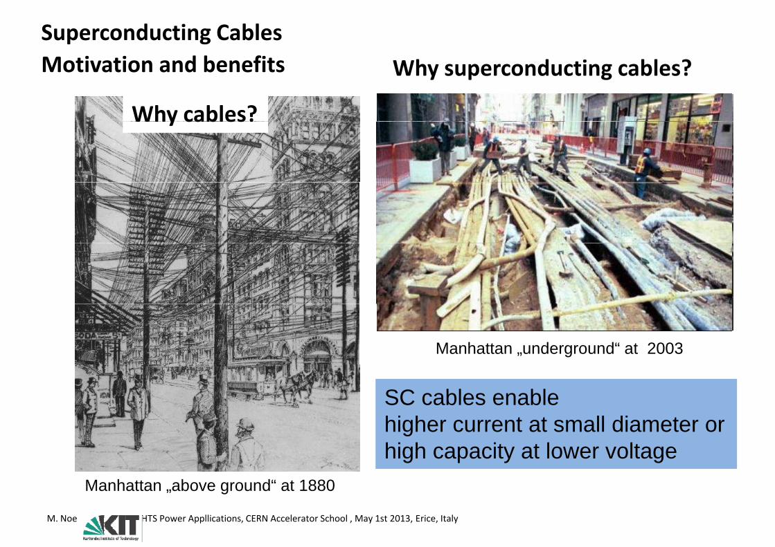
Superconducting CablesMotivation and benefits Wh d i bl ?Motivation and benefits Why superconducting cables?
Why cables?Why cables?
Manhattan „underground“ at 1900Manhattan „underground“ at 2003
SC cables enablehigher current at small diameter or
Manhattan above ground“ at 1880
higher current at small diameter orhigh capacity at lower voltage
M. Noe HTS Power Appllications, CERN Accelerator School , May 1st 2013, Erice, Italy
Manhattan „above ground at 1880

Superconducting CablesWhy not LTS Cables in Power Systems?Why not LTS Cables in Power Systems?
Courtesy: Dr. Heinz‐Werner Neumüller, former Siemens Corporate Technology
M. Noe HTS Power Appllications, CERN Accelerator School , May 1st 2013, Erice, Italy 13

Superconducting AC CablesWhy no long distance transmission with AC Cables?Why no long distance transmission with AC Cables?Long distance (> 100 km) transmission of high power (> 1 GW) ?
Cost comparison of overhead transmission line with conventional cable110 k di 1050
1170
110 km distance 380 kV transmission voltage2 Systems overhead transmission line
1050 Numbers in Mio. €
Systems overhead transmission line4 Systems 380 kV conventional cable 6.2:1
105190
85120Conventional AC cables are not yet used for long distance high power
t i i
Invest Loss Total+ =
transmission. Why should we use HTS AC cables?
OHTL-3x635/117 Al/StCable: 2XS(FL)2Y 1x2500 RM, fully compensated
M. Noe HTS Power Appllications, CERN Accelerator School , May 1st 2013, Erice, Italy 14
Source: B. Oswald, Freileitung/Erdkabel, 14.5.2009, Berlin
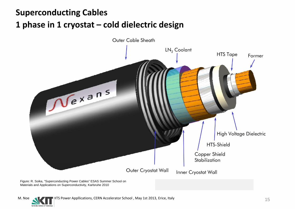
Superconducting Cables1 phase in 1 cryostat cold dielectric design1 phase in 1 cryostat – cold dielectric design
Figure: R. Soika, “Superconducting Power Cables” ESAS Summer School on Materials and Applications on Superconductivity, Karlsruhe 2010
M. Noe HTS Power Appllications, CERN Accelerator School , May 1st 2013, Erice, Italy 15
Materials and Applications on Superconductivity, Karlsruhe 2010
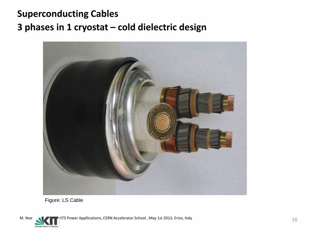
Superconducting Cables3 phases in 1 cryostat cold dielectric design3 phases in 1 cryostat – cold dielectric design
Figure: LS Cable
M. Noe HTS Power Appllications, CERN Accelerator School , May 1st 2013, Erice, Italy 16
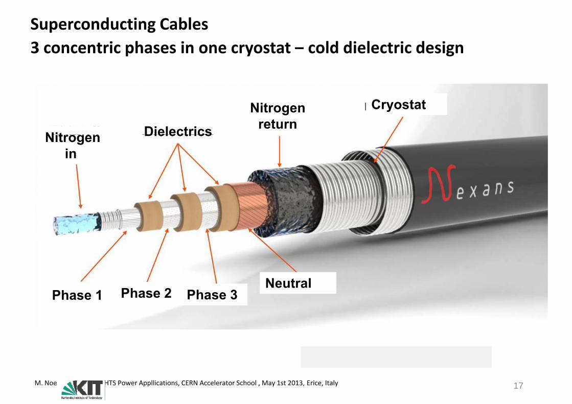
Superconducting Cables3 concentric phases in one cryostat cold dielectric design3 concentric phases in one cryostat – cold dielectric design
Cryostat
Nit
Nitrogen return DielectricsNitrogen
in Dielectrics
Neutral Phase 3 Phase 1 Phase 2
M. Noe HTS Power Appllications, CERN Accelerator School , May 1st 2013, Erice, Italy 17

Superconducting CablesCable TypesCable Types
3 phases in 1 cryostat1 phase in 1 cryostat 3 concentric phases p yp y
SCEl. Insulation
S d
Therm. InsulationLN2
pin 1 cryostat
CoreSupercond
LN2
• No strayfield • No strayfield N t fi ld• No strayfield• Longest lengths • Highest voltages
• No strayfield• compact design
• Low and medium high
• No strayfield• compact design• Low amount of SC
• gvoltages- • only for medium vpltage
M. Noe HTS Power Appllications, CERN Accelerator School , May 1st 2013, Erice, Italy 18
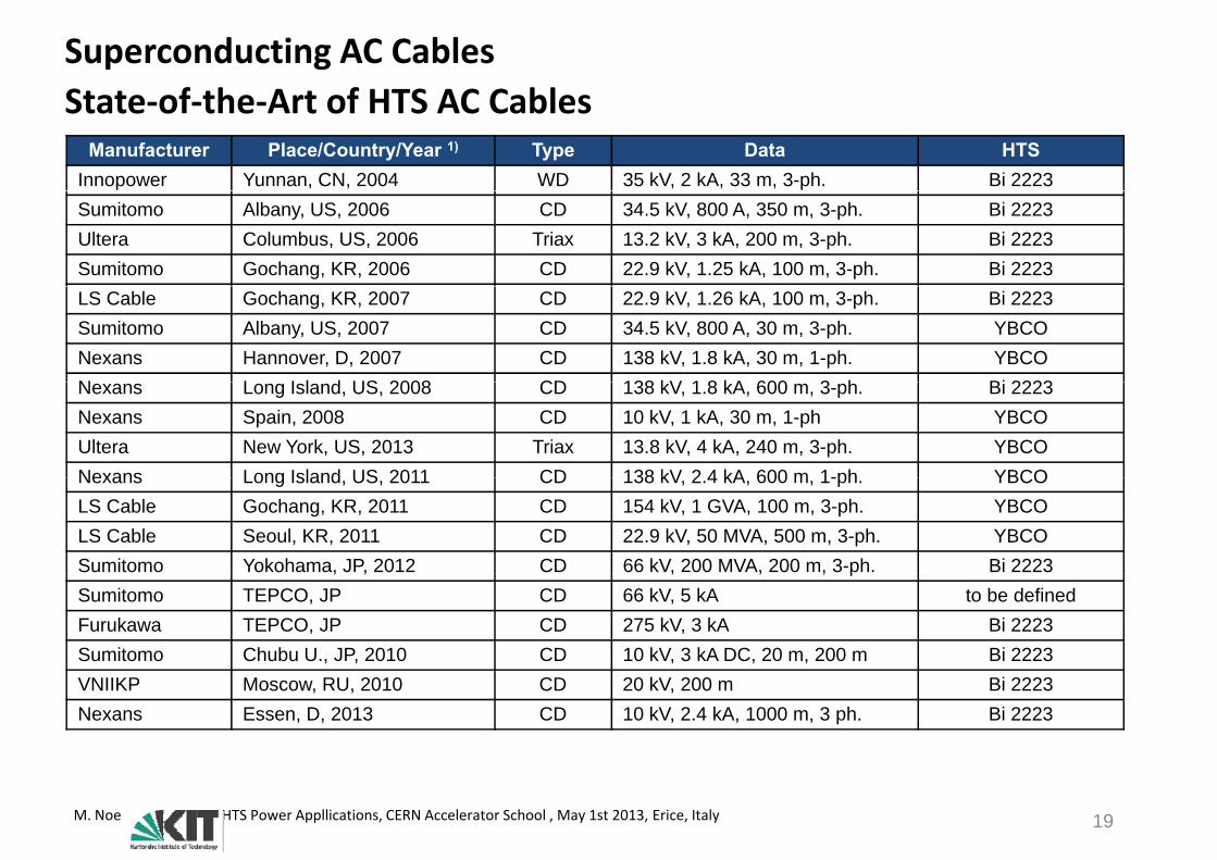
Superconducting AC CablesState of the Art of HTS AC CablesState‐of‐the‐Art of HTS AC Cables
Manufacturer Place/Country/Year 1) Type Data HTSInnopower Yunnan, CN, 2004 WD 35 kV, 2 kA, 33 m, 3-ph. Bi 2223Sumitomo Albany, US, 2006 CD 34.5 kV, 800 A, 350 m, 3-ph. Bi 2223Ultera Columbus, US, 2006 Triax 13.2 kV, 3 kA, 200 m, 3-ph. Bi 2223Sumitomo Gochang, KR, 2006 CD 22.9 kV, 1.25 kA, 100 m, 3-ph. Bi 2223LS Cable Gochang, KR, 2007 CD 22.9 kV, 1.26 kA, 100 m, 3-ph. Bi 2223Sumitomo Albany, US, 2007 CD 34.5 kV, 800 A, 30 m, 3-ph. YBCONexans Hannover, D, 2007 CD 138 kV, 1.8 kA, 30 m, 1-ph. YBCON L I l d US 2008 CD 138 kV 1 8 kA 600 3 h Bi 2223Nexans Long Island, US, 2008 CD 138 kV, 1.8 kA, 600 m, 3-ph. Bi 2223Nexans Spain, 2008 CD 10 kV, 1 kA, 30 m, 1-ph YBCOUltera New York, US, 2013 Triax 13.8 kV, 4 kA, 240 m, 3-ph. YBCONexans Long Island US 2011 CD 138 kV 2 4 kA 600 m 1-ph YBCONexans Long Island, US, 2011 CD 138 kV, 2.4 kA, 600 m, 1-ph. YBCOLS Cable Gochang, KR, 2011 CD 154 kV, 1 GVA, 100 m, 3-ph. YBCO LS Cable Seoul, KR, 2011 CD 22.9 kV, 50 MVA, 500 m, 3-ph. YBCOSumitomo Yokohama, JP, 2012 CD 66 kV, 200 MVA, 200 m, 3-ph. Bi 2223, , , , , pSumitomo TEPCO, JP CD 66 kV, 5 kA to be definedFurukawa TEPCO, JP CD 275 kV, 3 kA Bi 2223Sumitomo Chubu U., JP, 2010 CD 10 kV, 3 kA DC, 20 m, 200 m Bi 2223VNIIKP Moscow, RU, 2010 CD 20 kV, 200 m Bi 2223Nexans Essen, D, 2013 CD 10 kV, 2.4 kA, 1000 m, 3 ph. Bi 2223
M. Noe HTS Power Appllications, CERN Accelerator School , May 1st 2013, Erice, Italy 19

Superconducting AC CablesState of the Art of HTS AC Cable TestsState‐of‐the‐Art of HTS AC Cable Tests
Maximum rated current of conventional cables in air275 kV, 3 kA, Japan
RM
S
140
160LIPA II ´11 Gochang ´11
275 kV, 3 kA, Japan
ge /
kV
100
120Three phases coaxial1 phase in 1 cryostat3 phases in 1 cryostat
LIPA I ´08
se V
olta
g
80
100 3 phases in 1 cryostatIn red warm dielectric
Yokosuga ´04
Yokohama ´12
se-P
has
40
60
Albany ´06 Yunnan ´04
Pha
s
20
40 y
Gochang ´07Columbus ´06
k ´Moscow´ 09
Copenhagen ´01Icheon ´10
CurrentRMS / kA0 1 2 3 4
05
New York ´13Carollton ´01 Essen ´13
M. Noe HTS Power Appllications, CERN Accelerator School , May 1st 2013, Erice, Italy 20
CurrentRMS / kA

Superconducting AC CablesState of the ArtState‐of‐the‐Art
Columbus LIPA Gochang
Figure: LS Cable
Ultera13.2 kV, 3 kA, 200 mTriaxialTM Design
Nexans138 kV, 2.4 kA, 600
LS Cable22.9 kV, 50 MVA, 100 mBSCCO 2223
Figure: UlteraTriaxialTM Design
BSCCO 2223Energized 2006High reliability
600 mSingle coaxial design BSCCO 2223Energized 2008
BSCCO 2223Energized 2007500 m field test with YBCO in 2011
Ultera
Figure: Nexans
M. Noe HTS Power Appllications, CERN Accelerator School , May 1st 2013, Erice, Italy 21
High reliability Energized 2008 in 2011

Superconducting AC Cables40 MVA 10 kV 1 km
Project partners: RWE, Nexans, KIT
40 MVA, 10 kV, 1 km
10 kV, 2.3 kA (40 MVA), 1000 m
HTS cable with HTS FCLHTS cable with HTS FCL
Project started in September 2011
P t t t t f ll fi i h d Prototype test successfully finished
Commissioning by end of 2013
M. Noe HTS Power Appllications, CERN Accelerator School , May 1st 2013, Erice, Italy
Worlds first HTS system installation in a city center connecting two substations
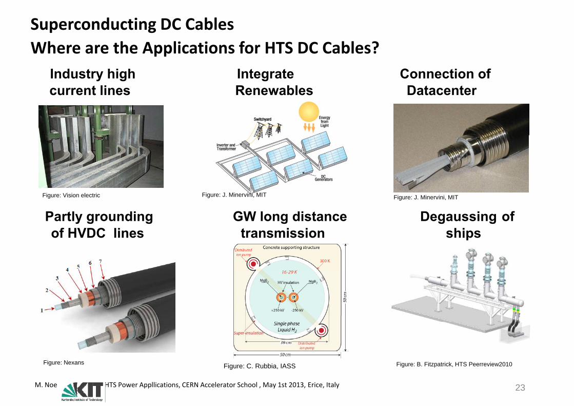
Superconducting DC CablesWhere are the Applications for HTS DC Cables?Where are the Applications for HTS DC Cables?
Industry high current lines
IntegrateRenewables
Connection of Datacentercurrent lines Renewables Datacenter
Partly grounding GW long distance Degaussing of
Figure: Vision electric Figure: J. Minervini, MIT Figure: J. Minervini, MIT
of HVDC lines transmission ships
Fi N
M. Noe HTS Power Appllications, CERN Accelerator School , May 1st 2013, Erice, Italy 23
Figure: Nexans Figure: C. Rubbia, IASS Figure: B. Fitzpatrick, HTS Peerreview2010

Superconducting DC CablesEnergy Efficiency Comparison of Copper and HTS CablesEnergy Efficiency – Comparison of Copper and HTS Cables
Specific lossAssumptions
Copper transmission line
Current density 1 0 A/mm2kAm
Wm
mmA
pCu 54,1757
11000
2
2 Copper at 20 °C
Current density 1.0 A/mm2
Specific conductivity 57 m/Ωmm2
Temperature value 0,0038kA
WmmA
pCu 2,221
10002
mm2
Copper at 90 °CMax. Temperature 85‐90 °C
HTSL DC transmission
kAmmmm
pCu
45 2
WWkAWWmmPP 2041150 2
pp
S Cryostat diameter 150‐200 mm
Cooling efficiency 1/15
Current lead loss 20W/kA
kAW
mWkAmPP
pCooling
CLCryov 120006,7
151
2
HTS
Current lead loss 20 W/kA
Cryostat loss 1 W/m2Example: 5 kA, 100 km
Copper (300 K) = 8770 kW
HTS DC cables can reduce transmission loss by more than 90 %
HTS = 712 kW
M. Noe HTS Power Appllications, CERN Accelerator School , May 1st 2013, Erice, Italy 24
HTS DC cables can reduce transmission loss by more than 90 %.

High Temperature Superconductor P A li tiPower Applications
MotivationConventional Power System Equipment• Cables, Rotating Machines, Transformers
New Power System Equipment• Current Limiters, SMES
Summary
M. Noe HTS Power Appllications, CERN Accelerator School , May 1st 2013, Erice, Italy 25
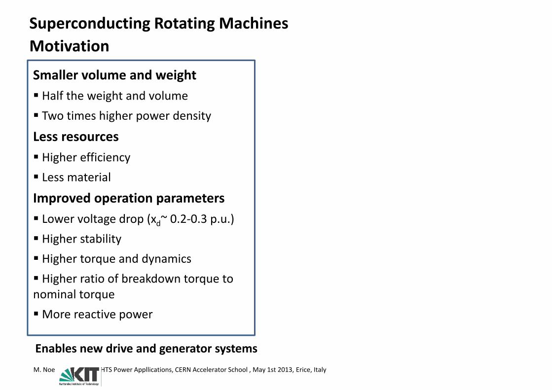
Superconducting Rotating MachinesMotivationMotivation
Smaller volume and weight Half the weight and volume Two times higher power density
Less resources Higher efficiency L i l Less material
Improved operation parameters L lt d ( ~ 0 2 0 3 ) Lower voltage drop (xd~ 0.2‐0.3 p.u.) Higher stability Higher torque and dynamicsHigher torque and dynamics Higher ratio of breakdown torque to nominal torqueMore reactive power
Enables new drive and generator systemsM. Noe HTS Power Appllications, CERN Accelerator School , May 1st 2013, Erice, Italy
Enables new drive and generator systems

Superconducting Rotating MachinesConventional synchronous machine (4 poles p 2)
Stator winding Parameter
Conventional synchronous machine (4 poles, p=2)
N
a‘cb
Stator windingRotor winding Torque/Lenght
BI.
.
c‘ b‘ Air gaprBIn rstat~
rBrA r1~.
SSaPower
nLrBA 2.
N
Power/Volume
nLrBA r1~
- Small air gap- Iron rotor
nBA r1~- Iron rotor- Stator winding in grooves
What is the impact of superconductivity?M. Noe HTS Power Appllications, CERN Accelerator School , May 1st 2013, Erice, Italy
What is the impact of superconductivity?

Superconducting Rotating MachinesConventional synchronous machine (4 poles p 2)
Stator winding
Conventional synchronous machine (4 poles, p=2)
ConventionelN
a‘cb
Stator windingRotor winding
Conventionel
B = 1 T
A 1
.
.
c‘ b‘ Air gap
A1 = 1 p.u.
P = 1 p.u.
.SSa
Loss
PCu,stat = 1 p.u.
.
N
PCu,rot = 1 p.u.
PFe = 1 p.u.- Small air gap- Iron rotor- Iron rotor- Stator winding in grooves
M. Noe HTS Power Appllications, CERN Accelerator School , May 1st 2013, Erice, Italy
Superconducting Rotating Machines
Superconducting synchronous machine(4 poles, p=2)
Conventional synchronous machine(4 poles, p=2)
N
a‘cb
N
a‘cb
Stator windingRotor winding
.
.
N
SSa
c‘ b‘ .
.
N
SS25-77 K
a
c‘ b‘Air gap
..
N
SSa
.
.
N
SSa
N N
CryostatDamper
- Copper stator winding AC- Superconducting rotor winding DC
ti t
- Small air gap- Iron rotor
- non-magnetic rotor- Air gap stator winding- Large air gap- Damper
- Stator winding in grooves
M. Noe HTS Power Appllications, CERN Accelerator School , May 1st 2013, Erice, Italy
- Damper
Superconducting Rotating Machines
Superconducting synchronous machine(4 poles, p=2)
Stator windingRotor winding
N
a‘cb Superconducting Conventionel
Air gap.
.
N
25-77 K
c‘ b‘
p g
B = 2 T
A1 = 2 p.u.
B = 1 T
A1 = 1 p.u.
.
.SSa
P = 4 p.u.
Loss
P = 1 p.u.
LossN
DamperPCu,stat = 2 p.u.
PCu,rot = 0 p.u. + PKälte
PCu,stat = 1 p.u.
PCu,rot = 1 p.u.
PFe = 0,6 p.u. PFe = 1 p.u.- Copper stator winding AC- Superconducting rotor winding DC - non-magnetic rotornon magnetic rotor- Air gap stator winding- Large air gap- Damper
M. Noe HTS Power Appllications, CERN Accelerator School , May 1st 2013, Erice, Italy
p
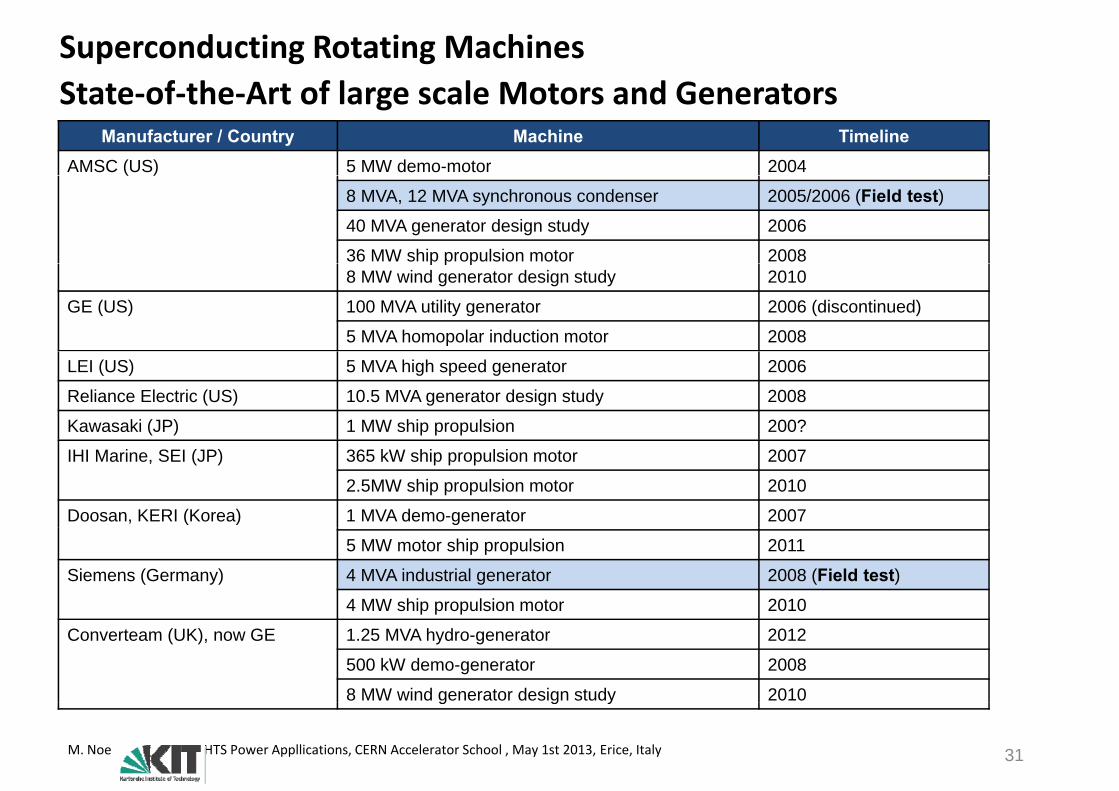
Superconducting Rotating MachinesState of the Art of large scale Motors and GeneratorsState‐of‐the‐Art of large scale Motors and Generators
Manufacturer / Country Machine TimelineAMSC (US) 5 MW demo-motor 2004( )
8 MVA, 12 MVA synchronous condenser 2005/2006 (Field test)40 MVA generator design study 2006
36 MW ship propulsion motor 2008p p p8 MW wind generator design study 2010
GE (US) 100 MVA utility generator 2006 (discontinued)
5 MVA homopolar induction motor 2008
LEI (US) 5 MVA high speed generator 2006
Reliance Electric (US) 10.5 MVA generator design study 2008
Kawasaki (JP) 1 MW ship propulsion 200?
IHI Marine, SEI (JP) 365 kW ship propulsion motor 2007
2.5MW ship propulsion motor 2010
Doosan, KERI (Korea) 1 MVA demo-generator 2007
5 MW motor ship propulsion 2011
Siemens (Germany) 4 MVA industrial generator 2008 (Field test)4 MW ship propulsion motor 2010
Converteam (UK), now GE 1.25 MVA hydro-generator 2012
500 kW demo-generator 2008
8 MW wind generator design study 2010
M. Noe HTS Power Appllications, CERN Accelerator School , May 1st 2013, Erice, Italy 31
g g y

Superconducting Rotating MachinesFor which Application?
1st Power Generator
For which Application?Peugeot ecar 1941
in Germany1891
10000 rpmElectric
1000 rpmPower
Generator
El t i
IndustryMotor
Aircraft
100 rpmShip
PropulsionElectric Cars
Hydro Generator
Container Ship 2010
10 rpm Wind Generator
0.1 MW 1 MW 10 MW 100 MW 1000 MW
There are many potential applications for HTS rotating machines that differ very much in rating torque and speed
M. Noe HTS Power Appllications, CERN Accelerator School , May 1st 2013, Erice, Italy 32
much in rating, torque and speed.
Superconducting Rotating Machines36 5 MW ship propulsion36.5 MW ship propulsion
Pi t fPicture from:Nature Physics 2, 794 - 796 (2006)doi:10.1038/nphys472Wired for the futureJohn Clarke & David C. Larbalestier
Image Courtesy of Converteam Image Courtesy of Siemens
AMSC36.5 MVA, 6 kV120 rpmp8 poles, 75 tonsEfficiency > 97 %Dimensions: 3,4 m x 4,6 m x 4,1 m
M. Noe HTS Power Appllications, CERN Accelerator School , May 1st 2013, Erice, Italy 33
Superconducting Rotating Machines4 MW Synchronous Generator4 MW HTS II – Long term field test at Siemens motor factory in Nuremberg
4 MW Synchronous Generator
Test results: Loss reduced by 50 % Full capacitive power High overload stability Low voltage drop Low total harmonic distortiondistortionMore than 7500 operating hours Safe operation
Figure: Siemens
None of the shutdowns caused by HTS winding or cooling!All operating states and shutdowns tolerated by the system!
M. Noe HTS Power Appllications, CERN Accelerator School , May 1st 2013, Erice, Italy
Superconducting Rotating Machines4 MW Size and Weight Comparison (Siemens)4 MW Size and Weight Comparison (Siemens)
Conventionel Maschine Superconducting Machine
Weight 11 to Weight 7 to
Image Courtesy of Siemens
M. Noe HTS Power Appllications, CERN Accelerator School , May 1st 2013, Erice, Italy 35

Superconducting Rotating Machines4 MW Energy Efficiency Comparison (Siemens)4 MW Energy Efficiency Comparison (Siemens)
100 %
80 %
100 %
60 %
80 %
Loss
40 %
20 %
0 %
Conventionel Superconducting
η=96,5 % η=98,7 %
M. Noe HTS Power Appllications, CERN Accelerator School , May 1st 2013, Erice, Italy 36
η 96,5 % η 98,7 %
Superconducting Rotating Machines1 7 MW Hydrogenerator (EU project Hydrogenie)1.7 MW Hydrogenerator (EU project Hydrogenie)
Objective
Partners
Develop and field test of a compact HTS hydro power generator
GE(Converteam)1.790 MW, 5.25 kV
PartnersGE (Converteam) UKPolitechnika Slaska Poland
214 rpm, 77.3 kNm28 poles, 32.7 tons
Politechnika Slaska, PolandKema, NederlandE ONWasserkraft Germany
4.7 m x 5.2 m x 3.5 mInstallation in 2012
E.ON Wasserkraft, GermanyZenergy Power, GermanyStirling Cryogenics NederlandStirling Cryogenics, NederlandCobham CTS, UK
Image Courtesy of Converteam
Successful test in 2013
M. Noe HTS Power Appllications, CERN Accelerator School , May 1st 2013, Erice, Italy 37
Successful test in 2013
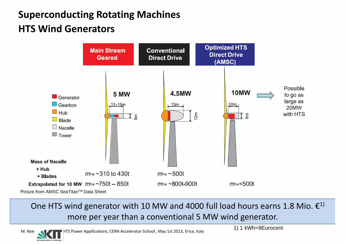
Superconducting Rotating MachinesHTS Wind GeneratorsHTS Wind Generators
TMPicture from AMSC SeaTitanTM Data Sheet
One HTS wind generator with 10 MW and 4000 full load hours earns 1.8 Mio. €1)more per year than a conventional 5 MW wind generator
M. Noe HTS Power Appllications, CERN Accelerator School , May 1st 2013, Erice, Italy
more per year than a conventional 5 MW wind generator.1) 1 kWh=9Eurocent

Superconducting Rotating MachinesSuprapower Project (http //www suprapower fp7 eu/)Suprapower Project (http://www.suprapower‐fp7.eu/)
Weight of the nacelleWeight of the nacelle‐ Reduced support structures and foundations‐ Reduction: SC generator and Direct DriveSC wire: MgB2
‐ based on economical and technical reasonsd i f i bili f‐ demonstration of viability for WT
Cryogenic system: conduction‐cooled (cryogen‐free)
Image Courtesy of Siemens
( y g )‐ Gifford‐McMahon cryocoolers ‐ Heat is removed by closed contact ‐ Compressors cannot rotate => High‐pressure ‐ Helium rotary feed‐through Industrially viable installable and
SC wind turbine according to Tecnalia concept (PTC/ES2009/070639)
Industrially viable, installable and environmentally sustainable
M. Noe HTS Power Appllications, CERN Accelerator School , May 1st 2013, Erice, Italy 39

Superconducting Rotating MachinesSuprapower Project (http //www suprapower fp7 eu/)Suprapower Project (http://www.suprapower‐fp7.eu/)
P tPartner‐ tecnaliaACCIONA WindPower‐ ACCIONA WindPower
‐ ACCIONA EnergiaColumbus Superconductors‐ Columbus Superconductors
‐ Oerlikon‐Leybold Vacuum‐ Institute of Electrical Engineering
Image Courtesy of Siemens
‐ Institute of Electrical Engineering Slovak Academic of Sciences‐ University of Southamptony p‐ KIT‐ d2m Engineering
SC wind turbine according to Tecnalia concept (PTC/ES2009/070639)
M. Noe HTS Power Appllications, CERN Accelerator School , May 1st 2013, Erice, Italy 40

Superconducting Rotating MachinesEnergy Efficiency of HTS Power GeneratorsEnergy Efficiency of HTS Power Generators
Source: High-Temperature Superconductivity for Power Engineering, Materials and Applications, Accompanying Book tothe Conference ZIEHL II Future and Innovation of Power Engineering with High-Temperature-Superconductors 16-17
M. Noe HTS Power Appllications, CERN Accelerator School , May 1st 2013, Erice, Italy 41
the Conference ZIEHL II, Future and Innovation of Power Engineering with High-Temperature-Superconductors, 16-17 March 2010, Bonn, Germany

Superconducting Rotating MachinesEnergy Efficiency of HTS Power GeneratorsEnergy Efficiency of HTS Power Generators
330000
Savings per generatorin Mio. € / a
CO2 reduction per generator in tons / a 1)
2
2,5
3
20000
25000
30000
in to
ns / a
o. €/ a
Efficiency increase 0.5 % Efficiency increase 0.5 %5 €cent per kWh
1
1,5
10000
15000
redu
ction i
ings in
Mio
0
0,5
0
5000CO2
Savi
300 400 500 600 700 800 900 1000 1100 1200300 400 500 600 700 800 900 1000 1100 1200
Generator Power / MW Generator Power / MW
M. Noe HTS Power Appllications, CERN Accelerator School , May 1st 2013, Erice, Italy 42
High Temperature Superconductor P A li tiPower Applications
MotivationConventional Power System Equipment• Cables, Rotating Machines, Transformers
New Power System Equipment• Current Limiters, SMES
Summary
M. Noe HTS Power Appllications, CERN Accelerator School , May 1st 2013, Erice, Italy 43
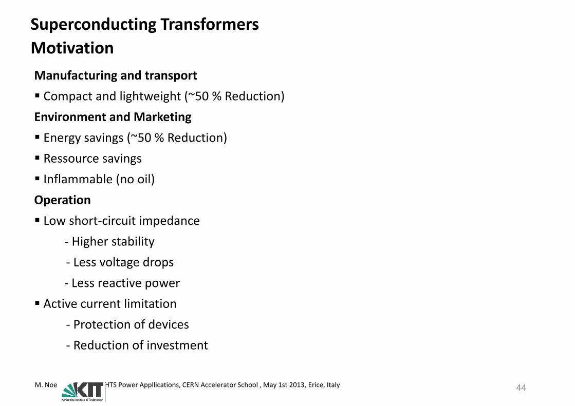
Superconducting TransformersMotivationMotivationManufacturing and transport Compact and lightweight (~50 % Reduction)Environment and Marketing E i (~50 % R d ti ) Energy savings (~50 % Reduction) Ressource savings Inflammable (no oil)Inflammable (no oil)Operation Low short‐circuit impedance p
‐ Higher stability‐ Less voltage drops‐ Less reactive power
Active current limitation‐ Protection of devices‐ Reduction of investment
M. Noe HTS Power Appllications, CERN Accelerator School , May 1st 2013, Erice, Italy 44

Superconducting TransformersDifferent typesDifferent types
Warm Iron Core Conduction CooledCold Iron Core
Iron CoreLN2 Iron Core
Coldhead
Iron CoreLN2
Cryostat Vacuum
Cryostat
Simple Cryostat
Iron at Room Temperature
Long recooling after quench
Low Cooling Power
Iron at Room Temperature
E i C t t
Simple Cryostat
Simple Cooling inerface
Hi h C li P Long recooling after quench
Temperature difference
Not suitable for high voltage
Expensive Cryostat
3 Cryostats needed
High Cooling Power (Iron core loss at low temp.)
M. Noe HTS Power Appllications, CERN Accelerator School , May 1st 2013, Erice, Italy 45
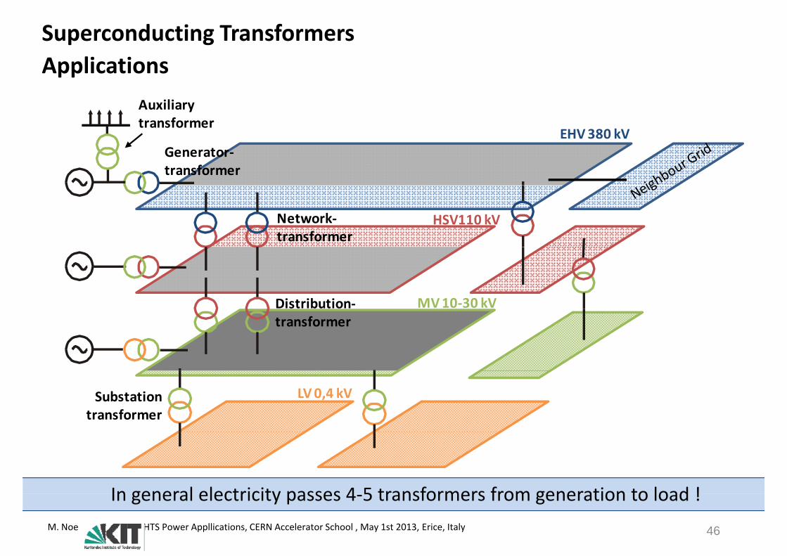
Superconducting TransformersApplicationsApplications
Auxiliarytransformer
EHV 380 kVGenerator‐transformer
transformer
HSV110 kVNetwork‐transformer
MV 10‐30 kVDistribution‐transformer
LV 0,4 kVSubstation transformer
In general electricity passes 4 5 transformers from generation to load !M. Noe HTS Power Appllications, CERN Accelerator School , May 1st 2013, Erice, Italy 46
In general electricity passes 4‐5 transformers from generation to load !
Superconducting TransformersState of the ArtState‐of‐the‐Art
Country Inst. Application Data Phase Year HTS
Switzerland ABB Distribution 630 kVA/18,42 kV/420 V 3 Dyn11 1996 Bi 2223
Japan Fuji Electric Kyushu Uni
Demonstrator 500 kVA/6,6 kV/3,3 kV 1 1998 Bi 2223
Germany Siemens Demonstrator 100 kVA/5,5 kV/1,1 kV 1 1999 Bi 2223
USA Waukesha Demonstrator 1 MVA/13,8 kV/6,9 kV 1 Bi 2223
USA Waukesha Demonstrator 5 MVA/24,9 kV/4,2 kV 3 Dy Bi 2223
Japan Fuji Electric U Demonstrator 1 MVA/22 kV/6,9 kV 1 < 2001 Bi 2223p jKyushu
,
Germany Siemens Railway 1 MVA/25 kV/1,4 kV 1 2001 Bi 2223
EU CNRS Demonstrator 41 kVA/2050 V/410 V 1 2003 P-YBCOS- Bi 2223
Korea U Seoul Demonstrator 1 MVA/22,9 kV/6,6 kV 1 2004 Bi 2223
Japan U Nagoya Demonstrator 2 MVA/22 kV/6,6 kV 1 2009 P-Bi 2223S YBCOS-YBCO
Germany KIT Demonstrator 1 MVA, 20 kV 1 2015 P-Cu/S-YBCO
USA Waukesha Prototype 28 MVA/69 kV 3 2013 YBCO
Japan Kyushu Demonstrator 400 kVA 1 2010 YBCO
Australlia Callaghan Innovation
Demonstrator 1 MVA 3 2013 YBCO
M. Noe HTS Power Appllications, CERN Accelerator School , May 1st 2013, Erice, Italy 47
Active current limitation

Superconducting Transformers28 MVA 70 kA Prototype28 MVA, 70 kA PrototypeProject Partners: SuperPower, Waukesha, SCE, ORNL, U Houston
Parameter Value
Objective: Develop and field test a 28 MVA HTS transformer using YBCO
Parameter Value
Primary voltage 70.5 kV
Secondary voltage 12.47 kV
Operating Temperature ~ 70 K, press. LN2 (1.1‐3 bar)
Target Rating 28 MVA
Primary Connection Delta
Secondary connection Wye
YBCO tape length ~ 12 km of 12 mm wide tapeYBCO tape length 12 km of 12 mm wide tape
HV rated current 230 A
LV rated current 1296 A
Source: F. Roy, “The 28‐MVA FCL Smart Grid Demo Transformer and Modeling Concerns about its Operation under Fault Conditions,” 2nd International Workshop on Modeling HTS, April 11‐13, 2011, Cambridge,
M. Noe HTS Power Appllications, CERN Accelerator School , May 1st 2013, Erice, Italy 48
United Kingdom.
Superconducting Transformers1 MVA Technology Demonstrator1 MVA Technology DemonstratorProject Partners: Callaghan Innovation, Wilson Transformers, General Cable Objective: Develop and field test of a 1 MVA HTS Transformer with YBCO:
HV Winding LV Winding
Objective: Develop and field test of a 1 MVA HTS Transformer with YBCO:
Source: IRLYBCO Roebel CableL = 20 m15 strands
4 mm wide YBCOI/Ic ~ 25%Polyimide wrap insulation
Source: IRLFi HTS R b l i i fi ld !
15 strands5 mm widthIc ~ 1400 A @ 77 K, sf
Polyimide wrap insulation24 double pancakes
M. Noe HTS Power Appllications, CERN Accelerator School , May 1st 2013, Erice, Italy 49
First HTS Roebel wire in field test!
Superconducting Transformers400 kVA Demonstrator400 kVA DemonstratorProject Partners: Kyushu Electric Power, Kyushu University
Objective: Develop 20 MVA transformer using YBCO
Data of 400 kVA demonstrator tested in 2010
Parameter Value
Primary Voltage 6.9 KVy g
Secondary Voltage 2.3 kV
Op. Temp. LN2 at ‐207°C
Target Rating 400 kVA
LV Rated Current 174 A
HV R d C 58 AHV Rated Current 58 A
Source: Superconductivity WEB21, Winter 2011, January 17 2011 D=565 mm D=738 mm
M. Noe HTS Power Appllications, CERN Accelerator School , May 1st 2013, Erice, Italy 50
H=810 mmD 738 mmH=2300 mm
Superconducting Transformers at KITTest experience of recovery under load after fault limitation
V763 32 i
Test experience of recovery under load after fault limitation
ZiIOS R'SLXϭ
Source Transformer Load
0,2
0,3 V763‐32 isec
~ UOS
TS1
R'v
TS2
R'L
0,1
,
)
0 1
0,0i (A
Data:SN = 60 kVAU 1000 V
Recovery time
‐0,2
‐0,1
trec = 2,3 s
tlim= 60 ms
Up = 1000 VIp = 60 Auk = 1,58 %
0,0 0,5 1,0 1,5 2,0 2,5 3,0
‐0,3
lim
12 mm YBCO tape48 m , , , , , , ,
t (s)
F ll d i l l d d d i h 2G HTS i !
Ic= 272 A (77K, sf) Fault duration
M. Noe HTS Power Appllications, CERN Accelerator School , May 1st 2013, Erice, Italy 51
Full recovery under nominal load was demonstrated with 2G HTS wire!
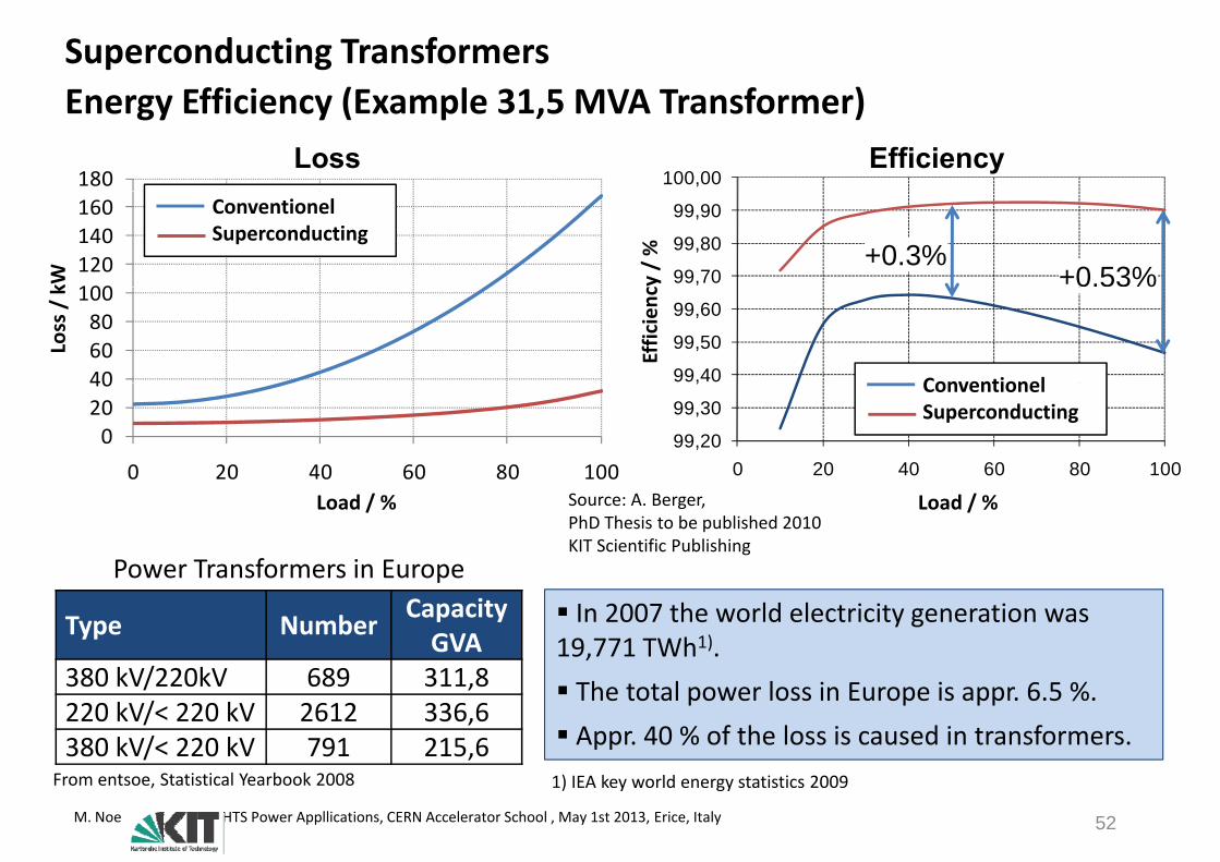
Superconducting TransformersEnergy Efficiency (Example 31 5 MVA Transformer)Energy Efficiency (Example 31,5 MVA Transformer)
180 100,00Loss Efficiency
100120140160
kW
ConventionelSuperconducting
99,70
99,80
99,90
cy / % +0.3%
+0.53%
406080
100
Loss / k
99,40
99,50
99,60
Conventionel
Efficienc
%
02040
0 20 40 60 80 10099,20
99,30
,
0 20 40 60 80 100
ConventionelSuperconducting
Power Transformers in Europe
0 20 40 60 80 100Load / % Load / %Source: A. Berger,
PhD Thesis to be published 2010KIT Scientific Publishing
Type Number CapacityGVA
380 kV/220kV 689 311 8
Power Transformers in Europe In 2007 the world electricity generation was 19,771 TWh1).
380 kV/220kV 689 311,8 220 kV/< 220 kV 2612 336,6 380 kV/< 220 kV 791 215,6
The total power loss in Europe is appr. 6.5 %. Appr. 40 % of the loss is caused in transformers.
M. Noe HTS Power Appllications, CERN Accelerator School , May 1st 2013, Erice, Italy 52
From entsoe, Statistical Yearbook 2008 1) IEA key world energy statistics 2009

High Temperature Superconductor P A li tiPower Applications
MotivationConventional Power System Equipment• Cables, Rotating Machines, Transformers
New Power System Equipment• Current Limiters, SMES
Summary
M. Noe HTS Power Appllications, CERN Accelerator School , May 1st 2013, Erice, Italy 53

Superconducting Fault Current Limiters
It is impossible to avoit short‐circuits!M. Noe HTS Power Appllications, CERN Accelerator School , May 1st 2013, Erice, Italy 54
It is impossible to avoit short‐circuits!

M. Noe HTS Power Appllications, CERN Accelerator School , May 1st 2013, Erice, Italy

Normal Operation Short-Circuit
unlimitedunlimited
ent
limitedC
urre
Ti
Ideal Fault Current Limiter
Time
Fast short-circuit limitation No or small impedance at normal operation
F t d t ti Fast and automatic recovery Fail safe Applicable at high voltages
M. Noe HTS Power Appllications, CERN Accelerator School , May 1st 2013, Erice, Italy
Applicable at high voltages Cost effective
Normal Operation Short-Circuit
unlimited
Recovery
unlimited
ent
limitedC
urre
Ti
Ideal Fault Current Limiter
Time
Fast short-circuit limitation No or small impedance at normal operation
F t d t ti Fast and automatic recovery Fail safe Applicable at high voltages
M. Noe HTS Power Appllications, CERN Accelerator School , May 1st 2013, Erice, Italy
Applicable at high voltages Cost effective

RecoveryNormal Operation Short-Circuit
unlimitedunlimited
ent
limitedC
urre
Ti
Ideal Fault Current Limiter SCFCL
Time
Fast short-circuit limitation No or small impedance at normal operation
F t d t ti
Fast and automatic recovery Fail safe Applicable at high voltages
M. Noe HTS Power Appllications, CERN Accelerator School , May 1st 2013, Erice, Italy
Applicable at high voltages Cost effective
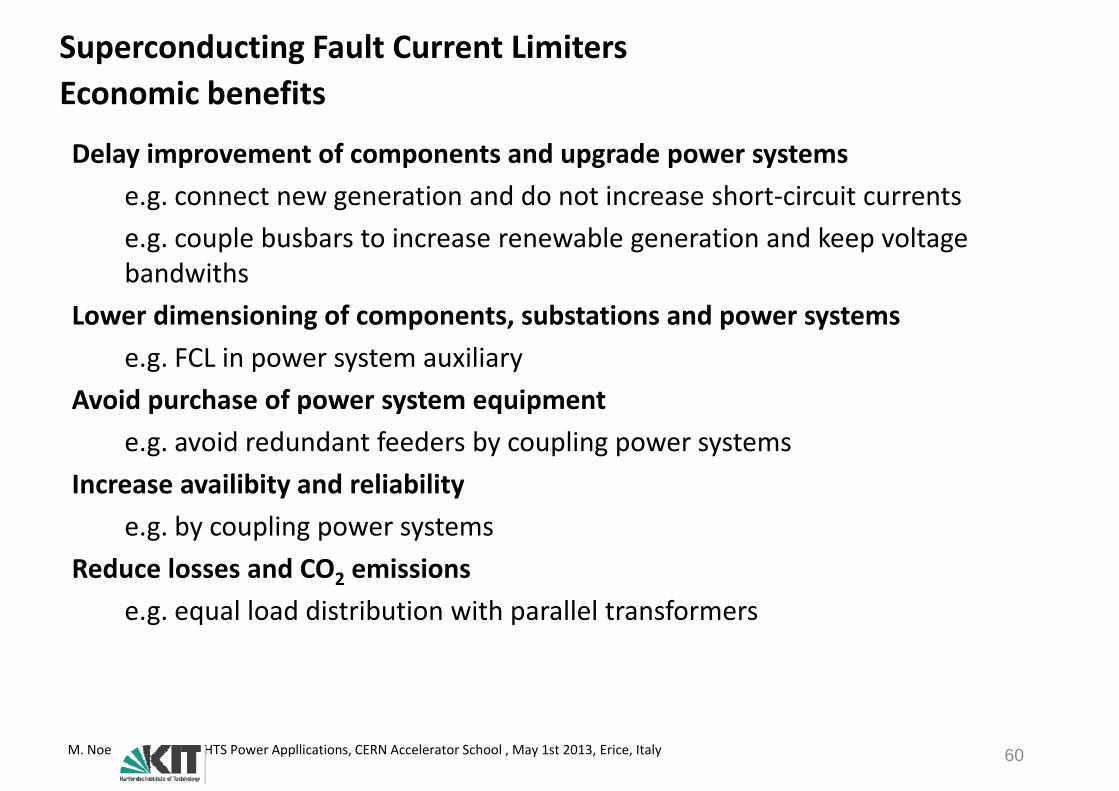
Superconducting Fault Current LimitersEconomic benefitsEconomic benefits
Delay improvement of components and upgrade power systemse.g. connect new generation and do not increase short‐circuit currentse.g. couple busbars to increase renewable generation and keep voltage b d i hbandwiths
Lower dimensioning of components, substations and power systemsFCL i t ilie.g. FCL in power system auxiliary
Avoid purchase of power system equipmente g avoid redundant feeders by coupling power systemse.g. avoid redundant feeders by coupling power systems
Increase availibity and reliability e g by coupling power systemse.g. by coupling power systems
Reduce losses and CO2 emissionse g equal load distribution with parallel transformerse.g. equal load distribution with parallel transformers
M. Noe HTS Power Appllications, CERN Accelerator School , May 1st 2013, Erice, Italy 60

Superconducting Fault Current LimitersApplicationsApplications
HöS 380 kVHöS 380 kV
HS 110 kV
MS 10‐30 kV
NS 0,4 kV
There are many applications for SCFCLs at different voltage levels.
M. Noe HTS Power Appllications, CERN Accelerator School , May 1st 2013, Erice, Italy 61
y pp g
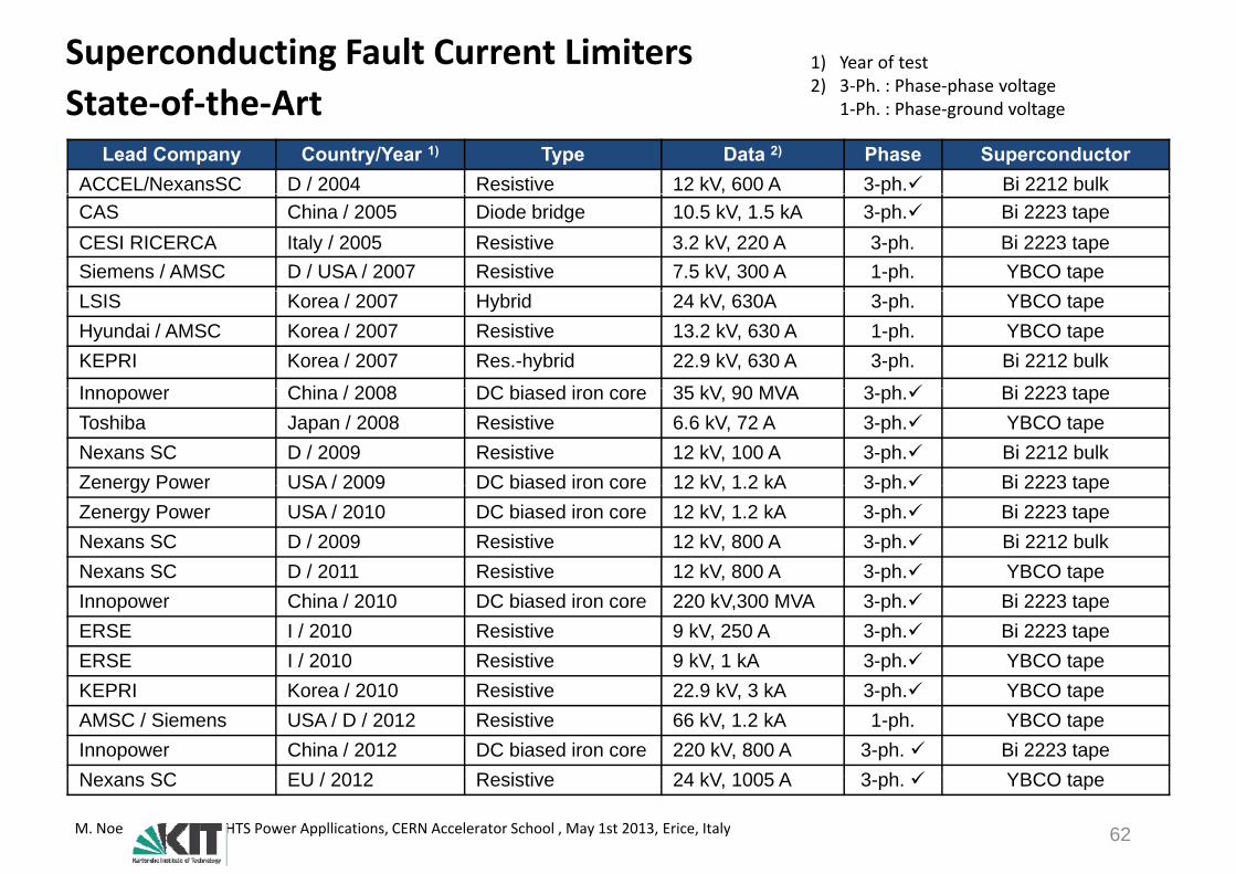
Superconducting Fault Current LimitersState of the Art
1) Year of test2) 3‐Ph. : Phase‐phase voltageState‐of‐the‐Art
Lead Company Country/Year 1) Type Data 2) Phase SuperconductorACCEL/NexansSC D / 2004 Resistive 12 kV, 600 A 3-ph. Bi 2212 bulk
1‐Ph. : Phase‐ground voltage
pCAS China / 2005 Diode bridge 10.5 kV, 1.5 kA 3-ph. Bi 2223 tapeCESI RICERCA Italy / 2005 Resistive 3.2 kV, 220 A 3-ph. Bi 2223 tapeSiemens / AMSC D / USA / 2007 Resistive 7.5 kV, 300 A 1-ph. YBCO tapeLSIS Korea / 2007 Hybrid 24 kV, 630A 3-ph. YBCO tapeHyundai / AMSC Korea / 2007 Resistive 13.2 kV, 630 A 1-ph. YBCO tapeKEPRI Korea / 2007 Res.-hybrid 22.9 kV, 630 A 3-ph. Bi 2212 bulkI Chi / 2008 DC bi d i 35 kV 90 MVA 3 h Bi 2223 tInnopower China / 2008 DC biased iron core 35 kV, 90 MVA 3-ph. Bi 2223 tapeToshiba Japan / 2008 Resistive 6.6 kV, 72 A 3-ph. YBCO tapeNexans SC D / 2009 Resistive 12 kV, 100 A 3-ph. Bi 2212 bulkZenergy Power USA / 2009 DC biased iron core 12 kV 1 2 kA 3-ph Bi 2223 tapeZenergy Power USA / 2009 DC biased iron core 12 kV, 1.2 kA 3 ph. Bi 2223 tapeZenergy Power USA / 2010 DC biased iron core 12 kV, 1.2 kA 3-ph. Bi 2223 tapeNexans SC D / 2009 Resistive 12 kV, 800 A 3-ph. Bi 2212 bulkNexans SC D / 2011 Resistive 12 kV, 800 A 3-ph. YBCO tapeInnopower China / 2010 DC biased iron core 220 kV,300 MVA 3-ph. Bi 2223 tapeERSE I / 2010 Resistive 9 kV, 250 A 3-ph. Bi 2223 tapeERSE I / 2010 Resistive 9 kV, 1 kA 3-ph. YBCO tapeKEPRI Korea / 2010 Resistive 22.9 kV, 3 kA 3-ph. YBCO tapeAMSC / Siemens USA / D / 2012 Resistive 66 kV, 1.2 kA 1-ph. YBCO tapeInnopower China / 2012 DC biased iron core 220 kV, 800 A 3-ph. Bi 2223 tapeNexans SC EU / 2012 Resistive 24 kV 1005 A 3 ph YBCO tape
M. Noe HTS Power Appllications, CERN Accelerator School , May 1st 2013, Erice, Italy 62
Nexans SC EU / 2012 Resistive 24 kV, 1005 A 3-ph. YBCO tape
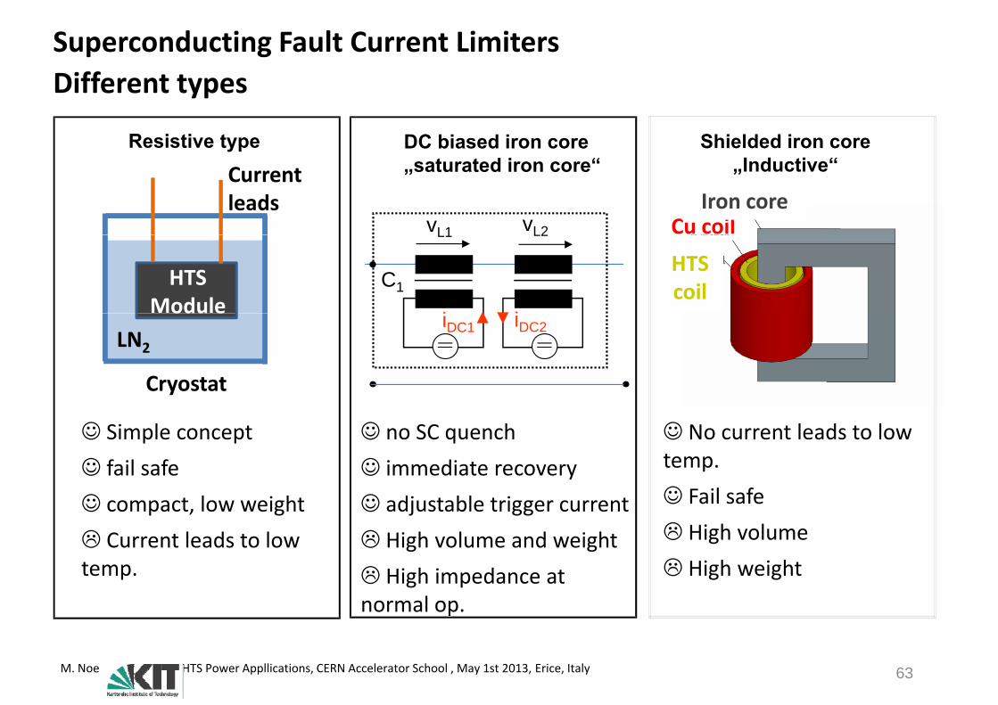
Superconducting Fault Current LimitersDifferent typesDifferent types
Shielded iron coreResistive type DC biased iron core„Inductive“
Cu coilIron core
„saturated iron core“
vL1 vL2
Currentleads
HTS coilC1
L1 L2
i i
HTS Module iDC1 iDC2
Cryostat
LN2
odu e
No current leads to low temp.
Simple concept fail safe
no SC quench immediate recovery
y
p Fail safe High volume
fail safe compact, low weight Current leads to low
immediate recovery adjustable trigger current High volume and weight
High weighttemp.g g
High impedance at normal op.
M. Noe HTS Power Appllications, CERN Accelerator School , May 1st 2013, Erice, Italy 63
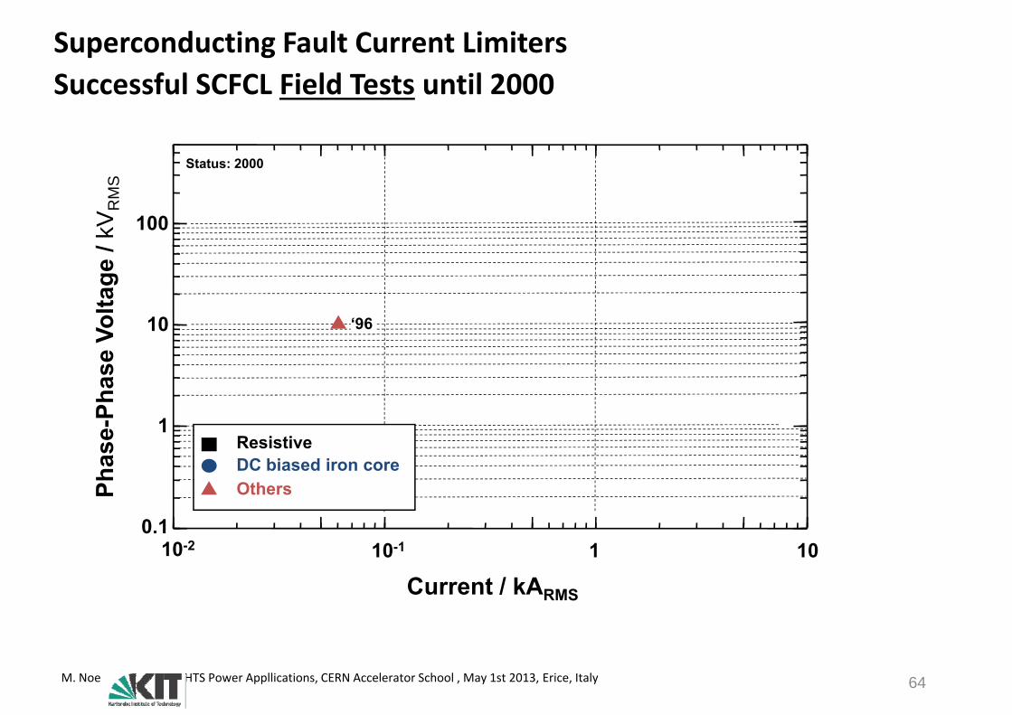
Superconducting Fault Current LimitersSuccessful SCFCL Field Tests until 2000
St t 2000
Successful SCFCL Field Tests until 2000
100kVR
MS
Status: 2000
10olta
ge /
‘9610
hase
Vo ‘96
hase
-Ph
1ResistiveDC biased iron core
10-2 10-1 1 100.1
Ph Others
10 10 1 10
Current / kARMS
M. Noe HTS Power Appllications, CERN Accelerator School , May 1st 2013, Erice, Italy 64
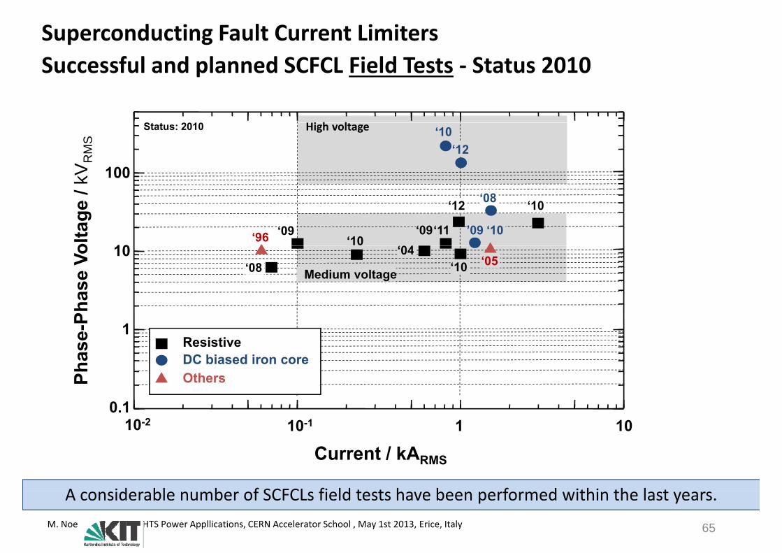
Superconducting Fault Current LimitersSuccessful and planned SCFCL Field Tests Status 2010
St t 2010
Successful and planned SCFCL Field Tests ‐ Status 2010
Hi h l
100kVR
MS
Status: 2010 ‘10‘12
High voltage
10olta
ge /
‘04‘96 ‘09
‘08
‘09 ’09 ‘10‘10
‘10
‘11
‘12
10
hase
Vo ‘04
‘08 ‘05‘10Medium voltage
hase
-Ph
1ResistiveDC biased iron core
10-2 10-1 1 100.1
Ph Others
10 10 1 10
Current / kARMS
A id bl b f SCFCL fi ld t t h b f d ithi th l tM. Noe HTS Power Appllications, CERN Accelerator School , May 1st 2013, Erice, Italy 65
A considerable number of SCFCLs field tests have been performed within the last years.
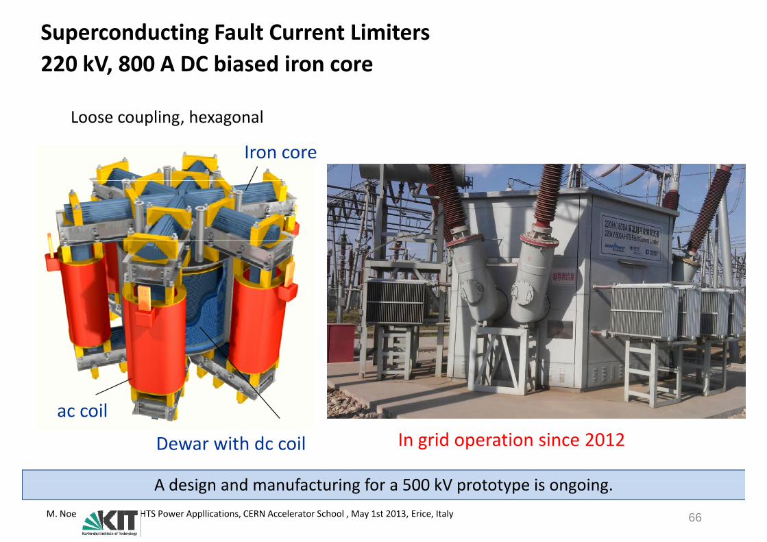
Superconducting Fault Current Limiters220 kV 800 A DC biased iron core220 kV, 800 A DC biased iron core
Loose coupling hexagonal
Iron core
Loose coupling, hexagonal
ac coil
Dewar with dc coil In grid operation since 2012
A d i d f t i f 500 kV t t i iM. Noe HTS Power Appllications, CERN Accelerator School , May 1st 2013, Erice, Italy 66
A design and manufacturing for a 500 kV prototype is ongoing.
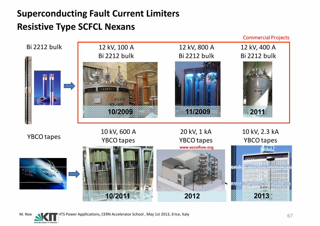
Superconducting Fault Current LimitersResistive Type SCFCL NexansResistive Type SCFCL Nexans
12 kV, 800 A12 kV, 100 A 12 kV, 400 ABi 2212 bulkCommercial Projects
,Bi 2212 bulk
,Bi 2212 bulk
,Bi 2212 bulk
11/2009 201110/2009
10 kV, 600 AYBCO tapes
10 kV, 2.3 kAYBCO tapes
20 kV, 1 kAYBCO tapesYBCO tapeswww.eccoflow.org
10/2011 2012 2013
M. Noe HTS Power Appllications, CERN Accelerator School , May 1st 2013, Erice, Italy 67

Superconducting Fault Current LimitersApplication Example (FP7 Project Eccoflow www eccoflow org)Application Example (FP7 Project Eccoflow: www.eccoflow.org)
Busbar Coupling Transformer FeederBusbar Coupling Transformer Feeder
Zshunt
FCLFCLCB
HTSRHTSCBHTS
Zshunt
RHTS
CB normally closed
CB normally open
Unique features of Eccoflow (1005A,24kV):One resistive SCFCL design fits two different applications One resistive SCFCL design fits two different applications
Two field tests with the same FCL will be performed in different applications Five utilities participate in this project
ll l dM. Noe HTS Power Appllications, CERN Accelerator School , May 1st 2013, Erice, Italy 68
A permanent installation is planned

Superconducting Fault Current LimitersApplication Example (FP7 Project Eccoflow www eccoflow org)Application Example (FP7 Project Eccoflow: www.eccoflow.org)
Air corereactor
x xCB1 HTS CB2
SFCL System
Arrangement
y
Container with HTS‐SFCL Standard MV Switchgear Air core reactors
Source: J Schramm et al Design and Production of the ECCOFLOW
First Field Installation in early 2013 at Endesa Grid in Majorca
M. Noe HTS Power Appllications, CERN Accelerator School , May 1st 2013, Erice, Italy
Source: J. Schramm et. al. „Design and Production of the ECCOFLOW resistive Superconducting Fault Current Limiter “, ASC Conference 2012, Portland USA
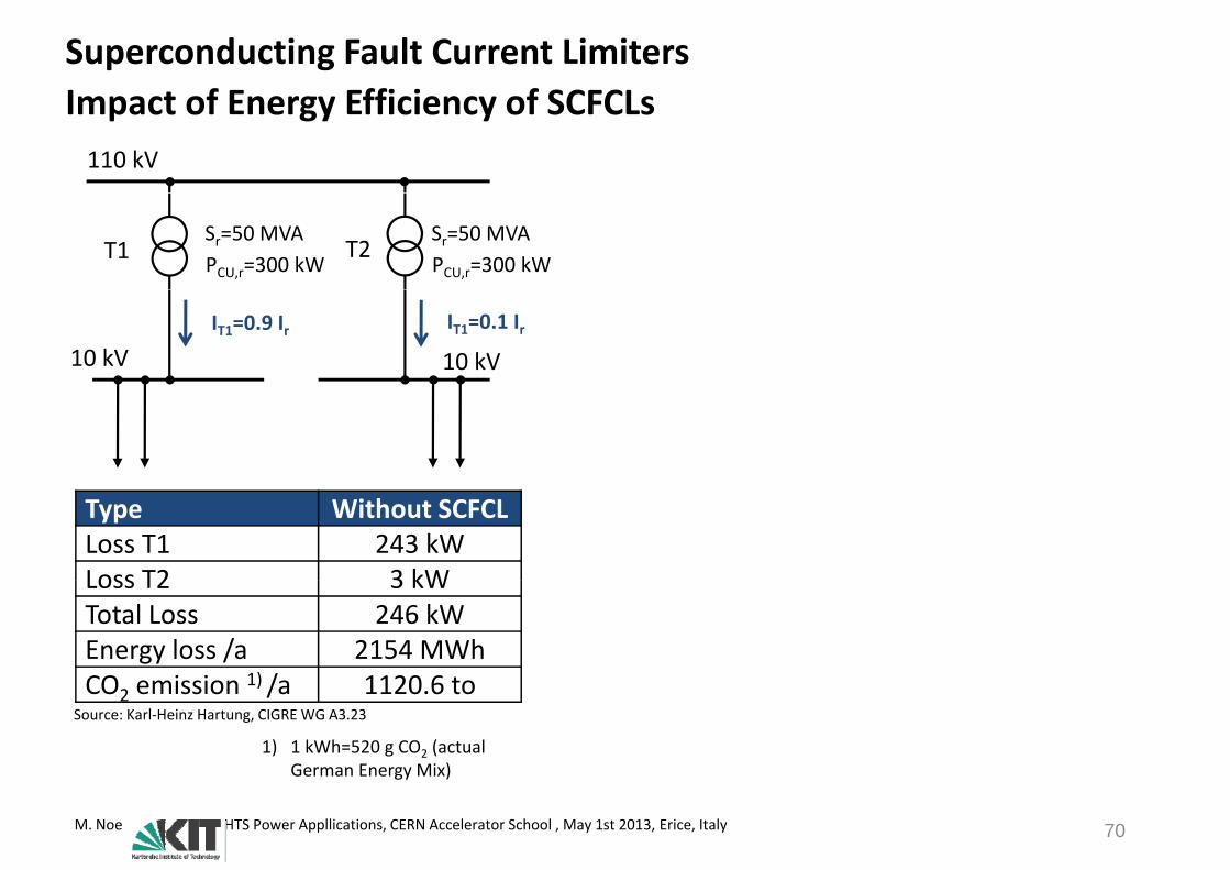
Superconducting Fault Current LimitersImpact of Energy Efficiency of SCFCLsImpact of Energy Efficiency of SCFCLs110 kV
T1 T2Sr=50 MVAPCU,r=300 kW
Sr=50 MVAPCU,r=300 kW
10 kV 10 kVIT1=0.9 Ir IT1=0.1 Ir
Type Without SCFCLLoss T1 243 kWLoss T2 3 kWLoss T2 3 kWTotal Loss 246 kWEnergy loss /a 2154 MWhCO i i 1) / 1120 6CO2 emission 1) /a 1120.6 to
Source: Karl‐Heinz Hartung, CIGRE WG A3.23
1) 1 kWh=520 g CO2 (actual German Energy Mix)
M. Noe HTS Power Appllications, CERN Accelerator School , May 1st 2013, Erice, Italy 70
German Energy Mix)

Superconducting Fault Current LimitersImpact of Energy Efficiency of SCFCLsImpact of Energy Efficiency of SCFCLs110 kV 110 kV
T1 T2Sr=50 MVAPCU,r=300 kW
Sr=50 MVAPCU,r=300 kW
T1 T2Sr=50 MVAPCU,r=300 kW
Sr=50 MVAPCU,r=300 kW
10 kV 10 kVIT1=0.9 Ir IT1=0.1 Ir
10 kV 10 kVIT1=0.5 Ir IT1=0.5 Ir
SCFCL
Type Without SCFCL With SCFCL DifferenceLoss T1 243 kW 75 kW ‐ 168 kWLoss T2 3 kW 75 kW +72 kWLoss T2 3 kW 75 kW +72 kWTotal Loss 246 kW 150 kW ‐ 96 kWEnergy loss /a 2154 MWh 1314 MWh ‐ 840 MWhCO i i 1) / 1120 6 683 2 437 4
1) 1 kWh=520 g CO2 (actual German Energy Mix)CO2 emission 1) /a 1120.6 to 683.2 to ‐ 437.4 to
Source: Karl‐Heinz Hartung, CIGRE WG A3.23
German Energy Mix)
Energy efficiency of SCFCLs has to be investigated on a case to case basisM. Noe HTS Power Appllications, CERN Accelerator School , May 1st 2013, Erice, Italy 71
Energy efficiency of SCFCLs has to be investigated on a case to case basis.
High Temperature Superconductor P A li tiPower Applications
MotivationConventional Power System Equipment• Cables, Rotating Machines, Transformers
New Power System Equipment• Current Limiters, SMES
Summary
M. Noe HTS Power Appllications, CERN Accelerator School , May 1st 2013, Erice, Italy 72

Superconducting Magnetic Energy StorageMotivationMotivation
Fuel Generation Transmission Distribution Customer/LoadFuel Generation Transmission Distribution Customer/Load
Energy StorageLarge scale Small scaleEnergy StorageLarge scale Small scale
Power QualityStabilityHigher
UtilizationLoad
BalanceStore
Renewables
Benefits
M. Noe HTS Power Appllications, CERN Accelerator School , May 1st 2013, Erice, Italy

Superconducting Magnetic Energy StorageBenefitsBenefits
• Short reaction time (ms)
• Fast charge and discharge• Fast charge and discharge
• 0‐100 % charging possible
• Independent supply of active and reactive power
• High efficiency
• No degradation
• Environmentally friendly• Environmentally friendly
M. Noe HTS Power Appllications, CERN Accelerator School , May 1st 2013, Erice, Italy
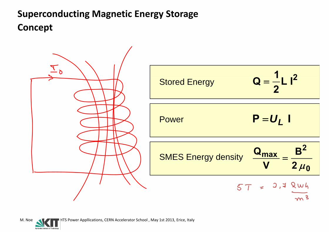
Superconducting Magnetic Energy StorageConceptConcept
2I1Q 2IL21Q Stored Energy
IP LUPower
SMES E d it2
max BQSMES Energy density0
max 2B
VQ
M. Noe HTS Power Appllications, CERN Accelerator School , May 1st 2013, Erice, Italy
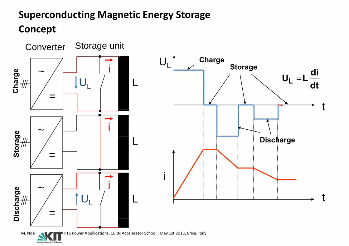
Superconducting Magnetic Energy StorageConcept
Converter Storage unit
Concept
U ddiLUL L
i~UL
ChargeStorage
arge
UL dtLL=
t
Cha
t
i~
ge DischargeL=St
orag
ii
~ge tLUL=
Dis
char
g
M. Noe HTS Power Appllications, CERN Accelerator School , May 1st 2013, Erice, Italy
D
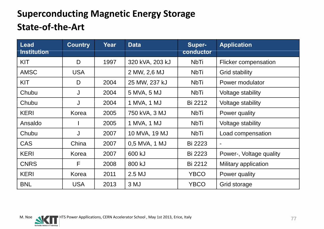
Superconducting Magnetic Energy StorageState of the ArtState‐of‐the‐Art
Lead Institution
Country Year Data Super-conductor
ApplicationInstitution conductorKIT D 1997 320 kVA, 203 kJ NbTi Flicker compensation
AMSC USA 2 MW, 2,6 MJ NbTi Grid stability
KIT D 2004 25 MW, 237 kJ NbTi Power modulator
Chubu J 2004 5 MVA, 5 MJ NbTi Voltage stability
Chubu J 2004 1 MVA 1 MJ Bi 2212 Voltage stabilityChubu J 2004 1 MVA, 1 MJ Bi 2212 Voltage stability
KERI Korea 2005 750 kVA, 3 MJ NbTi Power quality
Ansaldo I 2005 1 MVA, 1 MJ NbTi Voltage stability
Chubu J 2007 10 MVA, 19 MJ NbTi Load compensation
CAS China 2007 0,5 MVA, 1 MJ Bi 2223 -
KERI Korea 2007 600 kJ Bi 2223 Po er Voltage q alitKERI Korea 2007 600 kJ Bi 2223 Power-, Voltage quality
CNRS F 2008 800 kJ Bi 2212 Military application
KERI Korea 2011 2.5 MJ YBCO Power quality
BNL USA 2013 3 MJ YBCO Grid storage
M. Noe HTS Power Appllications, CERN Accelerator School , May 1st 2013, Erice, Italy 77
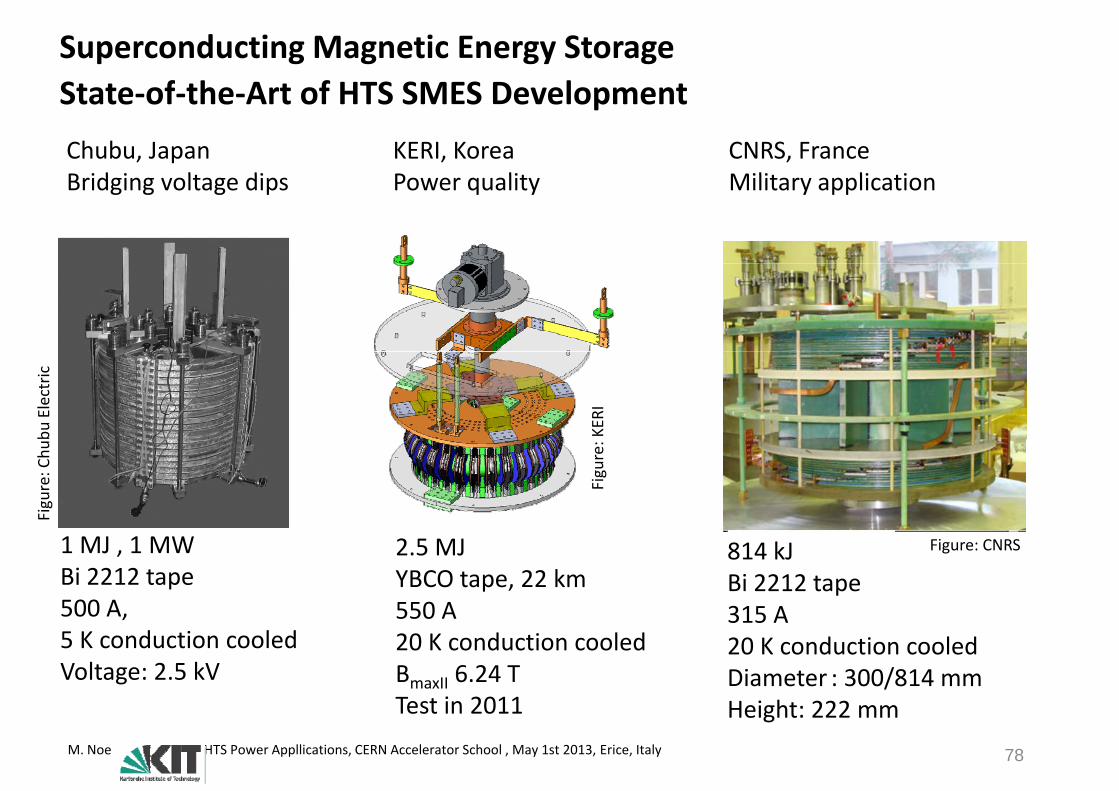
Superconducting Magnetic Energy StorageState of the Art of HTS SMES DevelopmentState‐of‐the‐Art of HTS SMES Development
KERI, KoreaP lit
CNRS, FranceMilit li ti
Chubu, JapanB id i lt di Power quality Military applicationBridging voltage dips
bu Electric
KERI
Figure: C
hu
Figure:
2.5 MJ YBCO tape, 22 km550 A
814 kJBi 2212 tape315 A
1 MJ , 1 MWBi 2212 tape500 A,
Figure: CNRS
550 A20 K conduction cooledBmaxII 6.24 TTest in 2011
315 A20 K conduction cooledDiameter : 300/814 mmH i ht 222
500 A, 5 K conduction cooledVoltage: 2.5 kV
M. Noe HTS Power Appllications, CERN Accelerator School , May 1st 2013, Erice, Italy 78
Test in 2011 Height: 222 mm

Superconducting Magnetic Energy Storage25 T 20 kW 3 MJ HTS prototype (2010 2013)Project Partners: SuperPower, ABB, Brookhaven National Lab., U Houston
25 T, 20 kW, 3 MJ HTS prototype (2010‐2013)
Objective: Develop and field test a HTS SMES for integrating renewables
Parameter ValueEnergy storage 3 MJP 20 kWPower 20 kWMagnetic field 25 TSuperconductor YBCO tapeSuperconductor YBCO tapeWire length 7 kmTape width 12 mmTape width 12 mmMinimum Ic 600 A
Source: Superconducting Magnetic Energy Storage (SMES) Systems for GRIDSQiang Li, Drew W. Hazelton, Venkat Selvamanickam, Presented by Traute Lehner, Tenth EPRI Superconductivity Conference, Tallahassee, FL, Oct. 12, 2011
M. Noe HTS Power Appllications, CERN Accelerator School , May 1st 2013, Erice, Italy
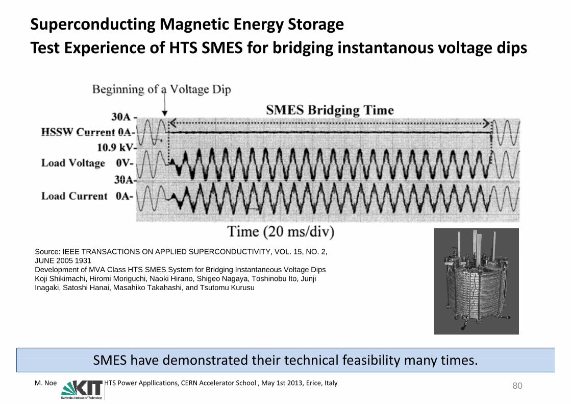
Superconducting Magnetic Energy StorageTest Experience of HTS SMES for bridging instantanous voltage dipsTest Experience of HTS SMES for bridging instantanous voltage dips
Source: IEEE TRANSACTIONS ON APPLIED SUPERCONDUCTIVITY, VOL. 15, NO. 2, JUNE 2005 1931Development of MVA Class HTS SMES System for Bridging Instantaneous Voltage DipsDevelopment of MVA Class HTS SMES System for Bridging Instantaneous Voltage DipsKoji Shikimachi, Hiromi Moriguchi, Naoki Hirano, Shigeo Nagaya, Toshinobu Ito, JunjiInagaki, Satoshi Hanai, Masahiko Takahashi, and Tsutomu Kurusu
SMES have demonstrated their technical feasibility many timesM. Noe HTS Power Appllications, CERN Accelerator School , May 1st 2013, Erice, Italy 80
SMES have demonstrated their technical feasibility many times.

High Temperature Superconductor P A li tiPower Applications
MotivationConventional Power System Equipment• Cables, Rotating Machines, Transformers
New Power System Equipment• Current Limiters, SMES
Summary
M. Noe HTS Power Appllications, CERN Accelerator School , May 1st 2013, Erice, Italy 81

Conclusions
HTS cables and SCFCL are very close to commercialization. HTS transformers, SMES and rotating machines will enter the market in the next decade.
HTS Material Research Directions for Power Applications
Higher production (Today a few 100 km/a for 2G) Lower cost (Less than 10 €/kA m)( / ) Stability of 2G wire Higher critical currents in low and high magnetic fieldsg g g
M. Noe HTS Power Appllications, CERN Accelerator School , May 1st 2013, Erice, Italy 82
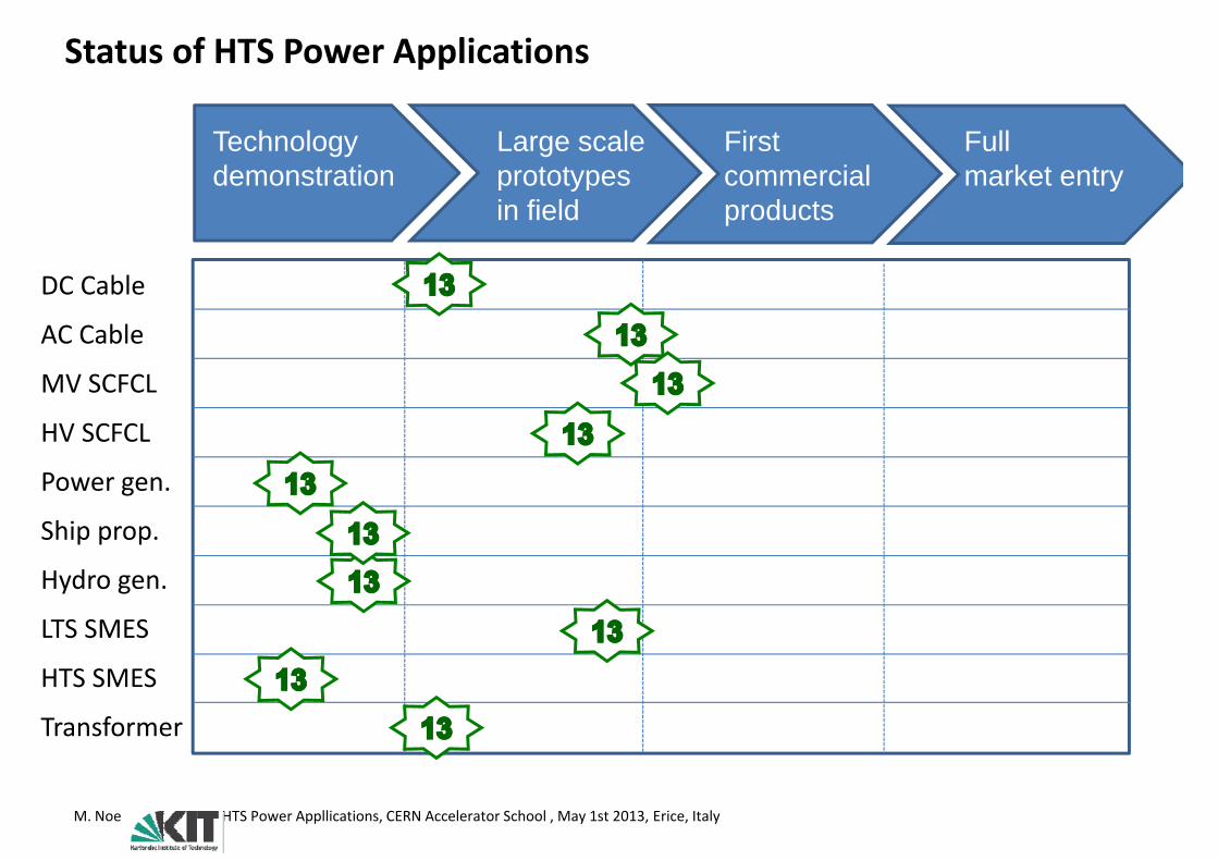
Status of HTS Power Applications
Technology demonstration
Large scaleprototypes
First commercial
Fullmarket entryy
in field productsy
DC Cable
AC Cable
MV SCFCL
DC Cable
MV SCFCL
Power gen
HV SCFCL
Power gen.
Ship prop.
H d
LTS SMES
Hydro gen.
HTS SMES
Transformer
HTS SMES
M. Noe HTS Power Appllications, CERN Accelerator School , May 1st 2013, Erice, Italy


![arXiv:1403.1869v1 [hep-ph] 7 Mar 2014 · arXiv:1403.1869v1 [hep-ph] 7 Mar 2014. 2 FIG. 1: (color online)A 1D topological superconductor pro-tected by the T2 = 1 time reversal symmetry](https://img.dokumen.tips/doc/110x75/5fd1a5a03c83b261c66d8c26/arxiv14031869v1-hep-ph-7-mar-2014-arxiv14031869v1-hep-ph-7-mar-2014-2-fig.jpg)