Embed Size (px)
Citation preview

HHO Hydrogen Generator Dry Cell Installation Manual Instructions
Presented by LaBella’s Auto Repair http://labellasautorepair.com
HHO Supplemental Hydrogen Generator Kits, Sales, Service, Testing,
Products
2642 Delaware Ave
Kenner, Louisiana 70062
504 469 9986
For support, contact us ONLY through the contact us/support form on our
website: http://www.labellasautorepair.com/contact_us.htm
TOPICS:
� WHAT WILL MY MILEAGE GAIN BE?
� SAFETY PRECAUTIONS
� LET'S GET FAMILIAR WITH YOUR NEW DRY CELL
� INSTALLATION
� DRY CELL PERFORMANCE NOTES
� PREVENTING DRY CELL FROM FREEZING
� VIEW OUT YOUTUBE HHO DRY CELL DEMO VIDEO
� INSTALLING THE DRY CELL AWAY FROM EXCESSIVE HEAT
� THE DRY CELL OPERATES ON 12 VOLTS
� CONNECTING THE POWER SOURCE
� HOW TO RUN YOUR HHO GAS INTO YOUR VEHICLE.
� HOW TO USE YOUR VACUUM
� HHO DIRECTIONAL NOZZLE
� FINAL SETUP
� ELECTROLYTE
� TEST RUN
� YOU WANT FUEL MILEAGE GAIN? YOU MUST LEAN THE SYSTEM
� THE SOLUTION NOW AVAILABLE HHO COMPUTER CHIP
� IF YOU DECIDE NOT TO USE THE HHO CHIP
� THE BEST ALTERNATIVE METHODS
� LEAST ALTERNATIVE METHODS
� ENGINEERS AND SCIENTIST HAVE PROVEN SUPPLEMENTAL HYDROGEN
WORKS GOING BACK TO THE 1800’S
� CLEANING THE DRY CELL-MY WATER IS BROWN
� INSTRUCTIONS ON HOW TO FLUSH
� EXTRA TIP FOR YOUR DIRTY LINES

MANUAL FOR DRY FUEL CELLS
HHO Hydrogen Generator Dry Cell Installation Manual Instructions
Presented by LaBella’s Auto Repair http://labellasautorepair.com
WHAT WILL MY MILEAGE GAIN BE?
We have that question frequently asked. The fact is the answer to that question cannot
properly be answered without stipulation. We might add, if one does so— we will be
polite here— he may be ignorant to the real extenuating facts. First of all, supplemental
hydrogen induced into any engine will not produce effective results UNLESS the engine
is in VERY GOOD running condition. This means if your engine has ANY of the
following problems: piston rings and/or valve(s), engine miss, check engine light on, oil
burning consumption, unusual smoke emitting from exhaust and/or breather system, or
overheating, or has not been tuned according to factory recommendations, DO NOT
expect any fuel mileage improvement. And don’t install anyone’s HHO system until it is
rectified by a professional that does mechanical work for a living and has ASE
(Automotive Service Excellence) certification credentials (see company profile:
http://www.labellasautorepair.com/index.htm#profile . Simply stated, HHO is not a fix-
all; but it is a proven fact that supplemental hydrogen reduces engine emissions and
increases fuel economy. Scientific documented proof of this fact can be read here:
http://www.labellasautorepair.com/bettermileage_howto.htm . However, supplemental
hydrogen must be installed properly and the engine and its computer, where applicable,
must be properly tuned for each application to accommodate the HHO induction. Placing
any kind of supplemental hydrogen generator system onto any engine, without addressing
the aforesaid, will yield little or no fuel mileage improvement. And if anyone leads you to
believe otherwise, you will inevitably be rudely awakened. We at LaBella’s Auto Repair
have been in the mechanical automotive repair business for a living, with proof
certification credentials upon request, in a real building structure, in a business zoned
location, with an address on it and a reachable phone number, in the national phonebook
Yellow Pages, with added proof location verification on the world-recognized Google
Earth (2641 Delaware Ave, Kenner, Louisiana 70062) not to mention the World Wide
Web— for over 40 years. We are not a backyard outfit in a residential neighborhood in
some off-the-wall, nameless-address location or in a house-attached garage with a phone
number or contact information that is seldom reached successfully. Make no mistake
about it, we are not saying you cannot do successful business with other companies that
may be different in there operations. We are only saying be vigilant. Make sure before
you make a purchase that there's real support if you have questions and need help. We
have a support form link on our website located on the navigation menu top left of every
page under “contact us support” http://www.labellasautorepair.com/contact_us.htm that is
monitored regularly to narrow down and pinpoint installation issue. Please do not call us
on our auto repair shop phone for support as it won’t put you in touch with the
HHO department. We are experts in engine diagnosis and the problems associated with
such and have a data base of factory repair manuals, wiring diagrams and test equipment

to make professional repairs and recommendations. Nonetheless, we can say with
reasonable confidence that those who have followed the aforesaid have gotten
satisfactory results from supplemental hydrogen installation and development— no
matter where they’ve made the purchase. The information herein is provided to ALL
viewers of our website with the idea of improving both fuel mileage and environmental
conditions.
Best wishes from LaBella’s Auto Repair and Company….
SAFETY PRECAUTIONS:
Incorrectly installing or incorrectly using our Hydrogen Dry Cell (or hydrogen generator)
may result in serious damage to your automobile or bodily injury. Read and follow the
instructions and safety precautions given here and in relevant places throughout this
manual to avoid these hazards. If you do not understand these instructions or do not like
working on vehicles, have your mechanic do the installation. Be sure to work outside, no
smoking; make sure the engine is not hot.
Be sure to wear goggles and rubber gloves and only use professional tools; use common
sense and general safety procedures used for automotive installations and maintenance. If
you're not sure, ASK! Yes, HHO is combustible – AFTER IT ENTERS THE ENGINE –
that's the whole point. Your Hydro Fuel Dry Cell system does not store hydrogen when
installed properly, so there is no fire hazard due to hydrogen storage. So, don't let people
who have no understanding of the system intimidate you or tell you about non-existent
hazards. Hydrogen dry cell technology cools down the engine and adds safety to any car.
The article “Shade Tree Safety” By Mike Bumbeck of autoMedia.com is a recommended
reading that will give more education for the do it yourself mechanic.
WORD OF CAUTION: Avoid unnecessary fears and that includes listening to self-
appointed “experts”. Because the safety notes in this manual are not intended to
intimidate or stop you, only to add to your safety.
LET'S GET FAMILIAR WITH YOUR NEW DRY FUEL CELL:


INSTALLATION:
The dry cell is the heart of the system that generates the HHO gas and cools down the
engine. You will need to find a place in the engine compartment to mount your new dry
cell. It MUST BE MOUNTED UPRIGHT WITH THE CHANNEL IRON MOUNTS
LEVEL TO THE GROUND & The fitting openings facing NORTH to the sky, and
NOT side mounted or it will not work properly and you will have unstable amp draw that
could blow the fuse. It should be mounted and secured in such a manner as to assure that
it cannot bounce around when the vehicle hits bumps etc. Your dry cell comes with
mounting holes which make your cell easy to install. Be sure to install your new dry cell
so that it can easily be accessed and can be conveniently cleaned and serviced or
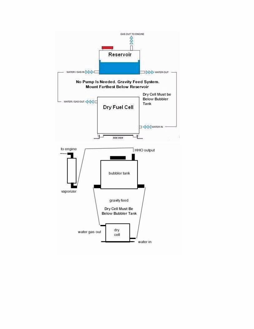
inspected from time to time. Your new dry cell comes with a Reservoir/Bubbler that
looks similar to the one above.

Make sure that your Reservoir/Bubbler is installed the same as you see in the illustration.
As you can see, the Reservoir/Bubbler needs to be higher than your dry cell. The distance
below the bubbler tank should be as follows: single dry cell 12-14 inches bellow. Multi
dry cells 14-16 inches bellow. It is important to make sure you have a nice straight drop
from your reservoir down to your dry cell with no snaking of the hoses. If that’s not
possible an assistant small water pump will be needed to optimize circulation and to
minimize water browning. For configurations where the distance from the tank to the cell
are greater than the suggested drop (over 12-16 inches) I recommend using a larger
pump. See full details from our associate HHO provider:
https://hydroclubusa.wordpress.com/hhopumps/ . Furthermore, heat the hose in warm
water before use to aid in flexibility and make sure ALL hose connections to the fittings
are securely tightened with hose clamps and in the rare event there happens to be a fitting
leaking at any of the threads, use Teflon tape or plumber's Goop to seal them according to
the product’s instructions. This system works off of gravity when the recommend hose
drop distance is met, it will not work properly if it's not installed right. If using twin
(double) dry cells, connect them only in parallel as seen in illustration above, including
the wiring; “in series” method should not be used as it will not work. The other important
device that needs to be installed with the dry cells is the vaporizer condenser. Some call
this a scrubber. This device needs to be installed upright as seen in the illustration and it
is important to make sure you are not running higher amp draw than the electrolyte mix
information dictates for your size engine as this will cause steam producing water vapor
rather than HHO gas. In any case, the vaporizer keeps the electrolyte from entering into
the engine which could be damaging to the engine causing cylinder washout or trigger the
check engine light. It also keeps electrolyte mix from entering the output line to the
bubbler tank. If you install the dry cell without this, you are taking a chance of the engine
sucking electrolyte into the intake manifold. This is particularly damaging to diesel
engines because it could easily cause engine lockup. If you're not sure of something
contact us through the contact us/support form on our website
http://www.labellasautorepair.com/contact_us.htm
DRY CELL PERFORMANCE NOTES:
Multiple dry cells can be used to increase HHO output capacity (LPM) if fuel mileage
gain is unsatisfactory. Keep in mind, however, for fuel mileage gain, follow the proper
electrolyte mix for your size engine for the correct amp draw. Too much amp draw
causes steam and over heating of the dry cell and produce less HHO gas. Also leaning of
the engine is necessary in most cases with the proper electronic devices which are
outlined herein. When proper leaning of the engine is accomplished but mileage is not
increased, you can try another dry cell in parallel and test the vehicle's fuel mileage,
carefully using the proper electrolyte mix ration to produce the correct amp draw for your
engine size engine. It is possible to use pairs of dry fuel cells with the same PWM and
bubbler tank accommodating them with added fitting at the bubbler tank as illustrated
above. Pairs of separate dry cells will run cooler than one large dry cell in most cases. If
you try running the extra pair of dry fuel cells using the same fittings, the electrolyte mix
and gas won’t flow as well and the use of a small electric water pump will be needed as
afore mentioned. Nonetheless, the dry cell will only perform at it best after the engine has

reached full running temperature with the factory recommended engine thermostat
(engines that run too cool or do not reach factory recommended running temperature will
not experience the best fuel mileage gain). Experience has shown that short runs will
yield less fuel mileage gains whereby the longer the run the better the fuel mileage gain
because the dry cell must warm up to run at its full performance capacity. Average warm
up time is 10 minutes. Thus if you drive short runs of that duration with a full cooling
down of the engine in between the runs, you will not see much fuel mileage gain.
PREVENT DRY CELL FROM FREEZING:
In regard to freezing temperatures, the electrolyte mix information addresses how to keep
the dry cell from freezing, which can damage the sealing gaskets, causing it to leak.
VIEW OUR YOUTUBE HHO DRY CELL DEMO VIDEO:
http://www.youtube.com/watch?v=X6p_udDj0zA
INSTALLING THE DRY CELL AWAY FROM EXCESSIVE HEAT:
Try to install your new dry cell as far away from the heat of your engine. Locate the
coolest available place in the engine area. We cannot give you an exact number here for
what is “too hot”, because there is a combination of heating factors here. There is a
situation called Thermal Runaway, where an increase in ambient temperature combined
with to high of electrolyte mix can lead to a destructive result to the dry cell. You can
prevent this from happening by following instructions below and utilizing what’s called a
pulse width modulator (PWM) to keep a stable amp draw to the dry cell. The electrolyte
mix information addresses this more in detail.
THE DRY CELL OPERATES ON 12 VOLTS:
Your new dry cell device is operated by vacuum pressure from your vehicle’s engine,
plus a 12 Volt supply from your vehicle’s electrical system. The device is designed to
operate on 12 Volts. Refer to the wiring diagrams. If you’re not sure, consult with your
auto mechanic, or contact us through the contact us/support form
http://www.labellasautorepair.com/contact_us.htm
CONNECTING THE POWER SOURCE:
Please refer to the wiring illustration below for typical wiring configuration for powering
the dry cell. We recommend the diagrams that utilize a relay, an amp meter and switch as
depicted in the following titled diagrams: “Typical Wiring Diagram Without PWM” and
“Typical PWM wiring Diagram With Amp Meter.” Some PWM’s may or may not use a
cooling fan.


1. Identify a point in your vehicle’s electrical system which has 12 Volts (positive)
present ONLY WHEN THE ENGINE IS IN THE RUNNING ignition position for
connecting to the dry cell positive electrical connection terminal. Be sure to install an
amp meter where you can easily view the amp draw of the dry cell at all times, possibly
inside the vehicle. If you use a pulse width modulator (PWM), this can aid in a stable
amp draw to the dry cell because you can set the amp draw at a specific setting.

2. Connect the black terminal of dry cell to a good ground source near the dry cell. If
using a pulse width modulator (PWM), see illustration “Typical PWM Wiring Diagram
With Amp Meter.”
HOW TO RUN YOUR HHO GAS INTO YOUR VEHICLE:
Now it's time to connect the HHO gas output line to your vehicle. (Follow the diagram
below and read the following paragraph earmarked with “Important Note”).


HOW TO USE YOUR VACUUM:
Dry cell systems should be connected to the closest area to the throttle throat (throttle
body) and for more efficiency also connected directly to continuous intake manifold
vacuum as well, as illustrated (if you decide not to use the HHO dual connection gas
output method to the engine, eliminate the T fitting near the bubbler tank/vaporizer and
the break away T fitting at the continuous vacuum source and connect to the air intake
throttle throat as illustrated). The main objective is to suck the HHO gas into a place such
as the carburetor throat or fuel injection throttle body and into the intake manifold at idle,
where it can be automatically mix with the existing fuel/air mixture- supplemented.
Important Note: on the vacuum T fitting for the PCV modification, if you get a check
engine light on, eliminate this modification all together as in some cases it causes a lean
burn issue. However, before proceeding to make connections to the intake, install the
one-way check valves at the HHO gas output hoses going to engine as illustrated above
with the one-way valve flow toward engine. Do not install any clamps on the one-way
valve so in the event a flash back occurs the hose will blow off preventing entry into the
bubbler tank. Now for connecting the HHO gas output hoses to the engine. The best
connection spot on carburetors and injection systems is at the closest location to the
throttle body throat. Connect the output hose on the air filter container right above the
carburetor throat and on fuel injection system, right above the throttle body throat by
means of a fitting. On rubber duct type hoses, you can use a soldier gun and melt a hole
in the rubber duct closest to the throttle body and glue and screw the fitting into the hole
with Goop glue. The other HHO output hose should go to continuous vacuum at the
intake manifold such as a PCV valve or other continuous vacuum source closest to the
manifold with the use of a universal/break off vacuum T fitting, available at all auto parts
stores. Do NOT use the vacuum source for the brake booster. Please reference the
illustration details above very carefully, taking note of the break off points of the
universal T fitting for the HHO gas hose and the vacuum source. The HHO gas hose at
the universal T fitting is broken off at the ¼ section for restriction purposes and the 3/8
hose is pushed all the way up to the 3/8 section (it’s especially advisable not to cut the T
fitting to the 3/8 section at the HHO gas hose connection when connecting to the PCV
valve vacuum system as this may cause too large of a vacuum leak in the engine. The
purpose of the dual supply (dual HHO output) is that when the engine is idling, there is a
high vacuum pressure in the intake manifold. This pressure drops when you accelerate or
rev up the engine to higher RPM. At that moment, more vacuum is available in the air
intake for sucking up the HHO gas into the engine. On metal or hard plastic ducts,
remove and drill hole, thread it, install fitting, and then clean the metal shavings out of
the duct before installing it. On diesel or gas engines with turbo charger(s), the HHO
output hose goes into the intake system BEFORE the turbo charger. On twin turbo
chargers you will have to use a 3/8 T fitting at the end of the HHO output hose to run 2
additional hoses, one each, to each intake system BEFORE each turbo charger. 2, 3/8
elbow fittings will be needed to tap into the intake system to connect the output hoses to.

WARNING: If you put the HHO output hose into the intake AFTER the turbo
charger(s), the HHO system will become pressurized, damaging the HHO system. Diesel
engines may require more than 2 dry cells and they can be connected in the same manner
as the 2 cells but with the use of 4 or 5 way 3/8 vacuum connectors in place of the T
connectors in the 2 dry cell diagram. The use of a small water pump will be needed as
earlier outlined.
HHO GAS DIRECTIONAL NOZZLE:
Another trick in optimizing the HHO gas induction is to direct the HHO gas out line as
close as possible into the throttle throat by fabricating a directional nozzle so that it
directs the HHO gas right over the primary throat(s) be it a carbureted or fuel injected
engine. This also works on ALL non-turbo diesel and non-propane burning engines. It is
very important to direct the HHO gas into the throttle throat without the directional
nozzle obstructing any of the moving parts like the choke flap or throttle plate. This can
be fabricated with the use of 3/8 x ¼ NPT elbow fittings, a 3/8 vacuum T fitting and 3/8
OD clear tubing, copper tubing, or plastic tubing assembled with Goop glue as depicted
in the illustration. Sanding of the mating areas may be needed to get the fittings to tightly
fit into one another before gluing.
FINAL SETUP:
Filling the Reservoir/Bubbler with DISTILLED WATER & THE ELECTROLYTE
(KOH):

ELECTROLYTE:
Our website is available to anyone on the Internet. There is some information that is only
for those who paid for the product. For example, we have our own formula for the
electrolyte we use in our dry cells. This formula runs cleaner and more efficient then
most things on the market today. To access the electrolyte mix pdf go to our navigation
menu on the top left of any page and locate the link “Electrolyte Mix.” You will need the
password. The preliminary instructions that came inside your kit explains how to access
the electrolyte information with password. Please read all of the preliminary instructions
as well. It is critical to follow all of the electrolyte mix instructions carefully.
If in some rare event you don’t have the preliminary instructions on how to access the
electrolyte mix information, for the password contact us through the contact us/support
form with proof of purchase: http://www.labellasautorepair.com/contact_us.htm . Once
you have your mixture ready, pour it into the top of the Reservoir/Bubbler to just cover
the lower hole but not the upper one. This allows the dry cell to self bleed. Fill the
bubbler up to the water level line. (see sample diagram below) This is just a sample of a 2
quart Reservoir/Bubbler. Keep the tank only 75% full. While you are filling the unit, you
should be able to see water running down to your dry cell. If you don't see any water
going down the tube, this could mean you don't have the Reservoir/Bubbler high enough
above your dry cell or lines are kinked and bent. Always try to install your dry cell at the
recommended distance below the tank as afore outlined. The dry cell system should be
bled of all air before operating or unstable amp draw will occur and may cause main
power fuse to blow. There should be no need to use any other method for bleeding the
dry cell when properly mounted. If in the event there’s an issue bleeding the air out, you
can use a vacuum pump gun (like a Mityvac http://www.mityvac.com/ ) and collector jar
to perform the bleeding as indicated in image below at the outlet line to bubbler tank
connection. Also, low controlled air pressure (below 5 psi) may be utilized if a vacuum
gun it not available at the bubbler tank cap opening area with a wet rag around a
regulated air nozzle while blocking off all openings but the one at the dry cell outlet line
which would be placed in a container (jar or bucket) while utilizing eye, face, and
breathing protection.

TEST RUN:
1. Start by checking all your connections. Make sure your amp meter and inline fuse have
been installed.
2. Now start your vehicle. While it's running, watch for bubbling action inside of your
Reservoir/Bubbler. You should be able to see the gas entering the Reservoir/Bubbler
tank.
3. Now it's time to check how many amps your dry cell is pulling as outlined in the
electrolyte mix information. This dry cell was made to run at 10-12 amps without
overheating at all. It will produce over 1 liter of HHO gas per minute if you have
everything hooked up according to the instructions; that's all the hydrogen your vehicle
will need to see an improvement in fuel mileage when used in conjunction with the
proper EFIE’s..
4. If you have done everything right, within a short time, you will notice that the engine
starts to sound dramatically different. It will sound smoother and quieter. Your RPM's

may be unstable for a couple of minutes. This is normal. The HHO is starting to change
the combustion cycle and cancels the pinging and the engine is now adjusting to the
changes. Your RPM's will normalize in a couple of minutes.
For HHO fuel mileage gain you will need to lean out the engine for the HHO gas to take
effect. Depending on the vehicles you have installed the dry cell on, you will need to use
the proper EFIE’s to accomplish this, such as a computer chip, or O2 sensor devices.
YOU WANT FUEL MILEAGE GAIN??? YOU MUST LEAN THE SYSTEM:
Most modern-day fuel injected vehicles use a computer and oxygen sensing devices to
monitor and maintain the correct oxygen/fuel ratio. One of the key sensing devices is the
oxygen sensor or exhaust sensor, in some cases the AFR (air fuel ratio) sensor. Fuel
injected vehicles have one or more oxygen sensors installed in them. The computer
extrapolates what the air/fuel ratio is, based on the amount of oxygen in the exhaust, as
reported by the oxygen sensor.
When a fuel saving device is installed, such as an oxy hydrogen generator, the petroleum
based fuel is burned more completely. One of the results of this is that there is more
oxygen (and less unburned hydrocarbons) in the exhaust stream. This is a good thing, and
is in fact, what we are trying to achieve. However, the computer will perceive this
condition as a “too lean” air/fuel mix. In other words, what is now a desirable condition
in the exhaust will be interpreted as “not enough fuel”, and the computer will direct the
fuel injectors to increase the amount of fuel being pumped into the engine. The result is
that the oxygen sensor and computer prevents efficient combustion from occurring! In
other words, it cancels out most of the improvement we have just made.
The Solution
NOW AVAILABLE: HHO COMPUTER CHIP for OBDII: (systems from Jan. 1996 )
With this new computer chip (Volo Performance) you will eliminate having to use any
other EFIE’s such as used on 02, map/maf , coolant and air temperature sensors, etc. If in
the event you choose not to use this chip you will have to address the 02 sensor(s) before
(and where applicable after) the catalytic converter as well as other applicable sensors if
you expect to have fuel mileage gain. If you already have these on your vehicle and want
to use the chip, you must remove all other EFIE’s off the engine. We sell these on our
website. Contact us for pricing through the contact us/support form
http://www.labellasautorepair.com/contact_us.htm and we will need the year, make,
model and engine size to program the chip specific to your vehicle. It can be purchased
here: http://www.jerrylabella.com/labellas/fueledbywater.htm#Dry .
Here’s What the HHO Chip Does:
This chip is dynamic - which means it will consider oxygen levels in the exhaust, along
with engine speed and load, intake air temperature and volume, and many other variables

to determine the most efficient fuel delivery rate and timing at up to 256 separate load
points. When using HHO as a fuel supplement, the chip will adjust fuel delivery and
timing to optimize efficiency. It’s compatible with factory equipped
Turbo/Superchargers, diesel engines, Flex-Fuel, & HHO supplement systems. It is NOT
compatible with hybrid engine options, propane, or natural-gas Simple to install easy to
follow instructions, connects to the back of the OBII data link connector with only 4
wires. This is a proven device with great reviews and results.
IF YOU DECIDE NOT TO USE THE HHO CHIP:
Of foremost importance is the leaning of the oxygen sensor(s) which “tells” the computer
what the oxygen content is by providing a voltage on its signal wire between 0 and 1 volt.
450 millivolts (.45 volts) means that the fuel/air mixture is correct. Higher values means
the mix is rich (has too much gas), and lower voltages means the mix is lean. By adding
voltage to the sensor’s output, we can compensate for the additional oxygen in the
exhaust and lean out the vehicle to get maximum MPG.
You must use device(s) that enhances the signal to the (ECU), such as an EFIE
(electronic fuel injector enhancer) which goes on the oxygen sensor(s) BEFORE the
catalytic converter(s) and in other cases, also down stream oxygen sensor(s).
THE BEST ALTERNATIVE METHODS:
For 95 & older fuel injected vehicles W/O2 sensors and one map sensor we have a device
for leaning the engine. Contact us for pricing and shipping:
http://www.labellasautorepair.com/contact_us.htm
For OBDII systems 1996 and newer, we recommend this company to purchase O2 sensor
EFIE’s: http://www.fuelsaver-mpg.com/
You can consult with them for what you will specifically need for your make and model
vehicle.
LEAST ALTERNATIVE METHODS:
A map enhancer can be used but this device is not as beneficial as the O2 sensor EFIE’s
for fuel mileage gain. We sell a map enhancer for use with 5 volt map sensors systems,
NOT FOR FORD frequency based map sensors. You can purchase the mini map
enhancer here: http://www.labellasautorepair.com/fueledbywater.htm#Dry
For frequency based map sensors found on OBDII Fords 1996 and newer, contact:
http://www.fuelsaver-mpg.com/
O2 sensor isolators are not recommended as they do not work as well as the aforesaid.
ENGINEERS AND SCIENTIST HAVE PROVEN SUPPLEMENTAL HYDROGEN
WORKS GOING BACK TO THE 1800’S:

Despite all criticism as to whether supplemental hydrogen works to improve mileage and
cleaner emissions, recognized engineers and scientist have proven that it dose. See
documentation here: http://www.labellasautorepair.com/bettermileage_howto.htm
Given that fact, NO WARRANTY is expressed or implied concerning the use of these
devices for any particular application. Use of these devices is at your own risk. These
devices are not intended for use in violation of State or Federal law or regulations.
Compliance with any State or Federal laws or regulations is the responsibility of the
buyer. Please read our disclaimer: http://www.labellasautoreapair.com/disclaimer.htm
CLEANING THE DRY FUEL CELL- MY WATER IS BROWN: Browns Gas: My water is getting Very dirty, NOW WHAT? . . .
With all HHO systems the water color will change over time, which is why we
implement a 6 month periodic flush. Since the beginning of HHO, systems that produce ”
Browns Gas” share this common problem. The name “Browns Gas” seems quite fitting as
you we see a slight browning of the water in these systems ( as well as the inventors
name being Yull Brown ).
Although this is something seen across the board in the industry, we have always been
interested in how clean our cells stay compared to others. So not to worry, this is
something you will notice but also something to monitor. Proper flow will help keep the
KOH from burning up at an advanced rate, which is one of the causes of an advanced
browning. If your system is healthy your water should remain transparent for up to 4-6
months depending on use. Even if there is slight change in tint, you should still be able
see through your water.
The pump definitely helps in keeping good flow in any situation where the recommended
configuration is not able to be met. If you notice your water becoming murky, very dark
or browning at an advanced rate, you may begin to suspect that something foreign may
have entered into the process which led to this discoloration. It also may be possible that
your circulation is poor. I do not want you to get become stressed about this
discoloration, although we do want to try and keep the system clean as possible because
of its importance.
INSTRUCTIONS ON HOW TO FLUSH:
1. Empty system of current electrolyte (drain the system of the water which it is currently
holding).
2. Replace with Distilled White Vinegar.
3. With Tank Cap OFF, Turn HHO system on for 5-10 minutes allowing the vinegar to
flow through the system and cleanse from inside out.

4. Empty Again (repeat step 1).
5. Replace with new distilled water/KOH mixture.
If your drop is not of 12-14 inches for single dry cell and not 14-16 inches for multiple
dry cells with close to straight down with little to no snaking of the lines, you may be
experiencing poor circulation, which can speed up this browning process. See link below
on adding a small pump to your system
https://hydroclubusa.wordpress.com/hhopumps/
EXTRA TIP FOR YOUR DIRTY LINES:
This should clear things up. If you suspect your lines may be dirty, you can run a 1 parts
bleach/ 2 part water mixture through them to cleanse them of anything polluting your
system before firing it back up with the new clean mixture.
LaBella’s Auto Repair