Embed Size (px)
Citation preview

Human Factors Considerations in the Design and Evaluation of Flight Deck Displays and Controls Version 1.0
Michelle Yeh1, Young Jin Jo2, Colleen Donovan1, and Scott Gabree2
1 Federal Aviation Administration 800 Independence Avenue, SW Washington, DC 20591
2 John A. Volpe National Transportation Systems Center Cambridge, MA 02142
Final Report – November 2013 DOT/FAA/TC-13/44 DOT-VNTSC-FAA-13-09 Prepared for: Federal Aviation Administration Human Factors Division 800 Independence Avenue, SW Washington, DC 20591

ii
Notice This document is disseminated under the sponsorship of the Department of Transportation in the interest of information exchange. The United States Government assumes no liability for the contents or use thereof. The United States Government does not endorse products or manufacturers. Trade or manufacturers’ names appear herein solely because they are considered essential to the objective of this report.
iii
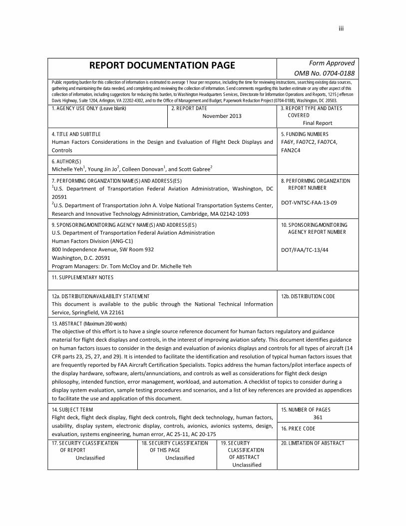
REPORT DOCUMENTATION PAGE Form Approved OMB No. 0704-0188
Public reporting burden for this collection of information is estimated to average 1 hour per response, including the time for reviewing instructions, searching existing data sources, gathering and maintaining the data needed, and completing and reviewing the collection of information. Send comments regarding this burden estimate or any other aspect of this collection of information, including suggestions for reducing this burden, to Washington Headquarters Services, Directorate for Information Operations and Reports, 1215 Jefferson Davis Highway, Suite 1204, Arlington, VA 22202-4302, and to the Office of Management and Budget, Paperwork Reduction Project (0704-0188), Washington, DC 20503. 1. AGENCY USE ONLY (Leave blank)
2. REPORT DATE November 2013
3. REPORT TYPE AND DATES COVERED
Final Report
4. TITLE AND SUBTITLE Human Factors Considerations in the Design and Evaluation of Flight Deck Displays and Controls
5. FUNDING NUMBERS FA6Y, FA07C2, FA07C4, FAN2C4
6. AUTHOR(S) Michelle Yeh1, Young Jin Jo2, Colleen Donovan1, and Scott Gabree2
7. PERFORMING ORGANIZATION NAME(S) AND ADDRESS(ES) 1U.S. Department of Transportation Federal Aviation Administration, Washington, DC 20591 2U.S. Department of Transportation John A. Volpe National Transportation Systems Center, Research and Innovative Technology Administration, Cambridge, MA 02142-1093
8. PERFORMING ORGANIZATION REPORT NUMBER
DOT-VNTSC-FAA-13-09
9. SPONSORING/MONITORING AGENCY NAME(S) AND ADDRESS(ES) U.S. Department of Transportation Federal Aviation Administration Human Factors Division (ANG-C1) 800 Independence Avenue, SW Room 932 Washington, D.C. 20591 Program Managers: Dr. Tom McCloy and Dr. Michelle Yeh
10. SPONSORING/MONITORING AGENCY REPORT NUMBER
DOT/FAA/TC-13/44
11. SUPPLEMENTARY NOTES
12a. DISTRIBUTION/AVAILABILITY STATEMENT This document is available to the public through the National Technical Information Service, Springfield, VA 22161
12b. DISTRIBUTION CODE
13. ABSTRACT (Maximum 200 words) The objective of this effort is to have a single source reference document for human factors regulatory and guidance material for flight deck displays and controls, in the interest of improving aviation safety. This document identifies guidance on human factors issues to consider in the design and evaluation of avionics displays and controls for all types of aircraft (14 CFR parts 23, 25, 27, and 29). It is intended to facilitate the identification and resolution of typical human factors issues that are frequently reported by FAA Aircraft Certification Specialists. Topics address the human factors/pilot interface aspects of the display hardware, software, alerts/annunciations, and controls as well as considerations for flight deck design philosophy, intended function, error management, workload, and automation. A checklist of topics to consider during a display system evaluation, sample testing procedures and scenarios, and a list of key references are provided as appendices to facilitate the use and application of this document.
14. SUBJECT TERM Flight deck, flight deck display, flight deck controls, flight deck technology, human factors, usability, display system, electronic display, controls, avionics, avionics systems, design, evaluation, systems engineering, human error, AC 25-11, AC 20-175
15. NUMBER OF PAGES 361
16. PRICE CODE
17. SECURITY CLASSIFICATION OF REPORT
Unclassified
18. SECURITY CLASSIFICATION OF THIS PAGE
Unclassified
19. SECURITY CLASSIFICATION OF ABSTRACT
Unclassified
20. LIMITATION OF ABSTRACT

SI* (MODERN METRIC) CONVERSION FACTORS APPROXIMATE CONVERSIONS TO SI UNITS
Symbol When You Know Multiply By To Find Symbol LENGTH
in inches 25.4 millimeters Mm ft feet 0.305 meters M yd yards 0.914 meters m mi miles 1.61 kilometers km
AREA in2 square inches 645.2 square millimeters mm2 ft2 square feet 0.093 square meters m2 yd2 square yard 0.836 square meters m2 ac acres 0.405 hectares ha mi2 square miles 2.59 square kilometers km2
VOLUME fl oz fluid ounces 29.57 milliliters mL gal gallons 3.785 liters L ft3 cubic feet 0.028 cubic meters m3 yd3 cubic yards 0.765 cubic meters m3
NOTE: volumes greater than 1000 L shall be shown in m3 MASS
oz ounces 28.35 grams g lb pounds 0.454 kilograms kg T short tons (2000 lb) 0.907 megagrams (or "metric ton") Mg (or "t") oz ounces 28.35 grams g
TEMPERATURE (exact degrees) oF Fahrenheit 5 (F-32)/9
or (F-32)/1.8 Celsius oC
ILLUMINATION fc foot-candles 10.76 lux lx fl foot-Lamberts 3.426 candela/m2 cd/m2
FORCE and PRESSURE or STRESS lbf poundforce 4.45 newtons N
lbf/in2 poundforce per square inch 6.89 kilopascals kPa APPROXIMATE CONVERSIONS FROM SI UNITS
Symbol When You Know Multiply By To Find Symbol LENGTH
mm millimeters 0.039 inches in m meters 3.28 feet ft m meters 1.09 yards yd
km kilometers 0.621 miles mi AREA
mm2 square millimeters 0.0016 square inches in2 m2 square meters 10.764 square feet ft2 m2 square meters 1.195 square yards yd2 ha hectares 2.47 acres ac
km2 square kilometers 0.386 square miles mi2 VOLUME
mL milliliters 0.034 fluid ounces fl oz L liters 0.264 gallons gal
m3 cubic meters 35.314 cubic feet ft3 m3 cubic meters 1.307 cubic yards yd3 mL milliliters 0.034 fluid ounces fl oz
MASS g grams 0.035 ounces oz
kg kilograms 2.202 pounds lb Mg (or "t") megagrams (or "metric ton") 1.103 short tons (2000 lb) T
g grams 0.035 ounces oz TEMPERATURE (exact degrees)
oC Celsius 1.8C+32 Fahrenheit oF ILLUMINATION
lx lux 0.0929 foot-candles fc cd/m2 candela/m2 0.2919 foot-Lamberts fl
FORCE and PRESSURE or STRESS N newtons 0.225 poundforce lbf
kPa Kilopascals 0.145 poundforce per square inch lbf/in2 *SI is the symbol for the International System of Units. Appropriate rounding should be made to comply with Section 4 of ASTM E380. (Revised March 2003)

v
Preface
This report was prepared by the Aviation Human Factors Division of the Safety Management and Human Factors Technical Center at the John A. Volpe National Transportation Systems Center. It was completed with funding from the Federal Aviation Administration (FAA) Human Factors Division (ANG-C1) in support of the Aircraft Certification Service Avionics Systems Branch (AIR-130) and the Technical Programs and Continued Airworthiness Branch (AIR-120). We would like to acknowledge the support of Dr. Tom McCloy, as the original Program Manager for this project. We would like to thank our technical sponsors, Dr. Kathy Abbott and Cathy Swider, as well as Jason Brys and Dr. Robert “Buck” Joslin, for reviewing and providing feedback on multiple iterations of this document. We are also very grateful to Dr. Stephanie Chase, Andrew Kendra, Matthew Isaacs, and Alan Yost at the Volpe Center for providing valuable input. We would also like to thank Margaret Jenny and Mary Beth Guaspari at RTCA, Inc. and Bruce Mahone and Martha Swiss at SAE for their support and assistance in helping us obtain copyright permission for using copyrighted text from several RTCA and SAE documents throughout this document.
Text excerpted from RTCA documents is copyrighted by RTCA, Inc. and has been reprinted with permission from RTCA, Inc. No further copying or distribution is permitted without permission. RTCA documents may be purchased from RTCA, Inc.:
RTCA, Inc. 1150 18th Street NW, Suite 910 Washington, DC 20036 Telephone: (202) 833 - 9339 Facsimile: (202) 833 - 9434 Internet: www.rtca.org
Text excerpted from SAE documents is also copyrighted and has been reprinted with permission from SAE International. No further copying or distribution is permitted without permission. SAE documents may be purchased from SAE International:
SAE International 400 Commonwealth Drive Warrendale, PA 15096-0001 - USA Internet: www.sae.org
The views expressed herein are those of the authors and do not necessarily reflect the views of the Volpe National Transportation Systems Center, the Research and Innovative Technology Administration, or the United States Department of Transportation.
Feedback on this document may be sent to Dr. Michelle Yeh ([email protected]) and Young Jin Jo ([email protected]). This document and other Volpe Center research documents can be found at: http://www.volpe.dot.gov/our-work/safety-management-and-human-factors/human-factors-publications-and-papers.

vi
This page left blank intentionally.

vii
Table of Contents List of Tables ....................................................................................................................... xix List of Figures ...................................................................................................................... xix Acronyms ............................................................................................................................ xxi Executive Summary ............................................................................................................ xxv 1 Introduction .................................................................................................................... 1
1.1 Technical Approach ........................................................................................................................ 2 1.2 Report Organization ....................................................................................................................... 3
2 Display Hardware ............................................................................................................ 5 2.1 Visual Display Characteristics ......................................................................................................... 5
FAA Regulatory and Guidance Material ..................................................................................................... 5 Display Size........................................................................................................................................... 5 Display Resolution ................................................................................................................................ 5 Luminance and Lighting ....................................................................................................................... 5 Glare and Reflections ........................................................................................................................... 8 Dimming ............................................................................................................................................... 8 Contrast ............................................................................................................................................... 8 Chromaticity ......................................................................................................................................... 9 Grayscale.............................................................................................................................................. 9 Display Response.................................................................................................................................. 9 Refresh Rate ....................................................................................................................................... 10 Display Defects ................................................................................................................................... 10
Other Recommendation(s) ...................................................................................................................... 10 General ............................................................................................................................................... 10 Luminance and Lighting ..................................................................................................................... 10 Refresh Rate ....................................................................................................................................... 11 Update Rate ....................................................................................................................................... 11 Display Response................................................................................................................................ 11
Background .............................................................................................................................................. 11 Example(s) ................................................................................................................................................ 12
2.2 Display Installation and Integration ............................................................................................. 13 FAA Regulatory and Guidance Material ................................................................................................... 13
General ............................................................................................................................................... 13 Installation ......................................................................................................................................... 14 Vibration ............................................................................................................................................ 15
Other Recommendation(s) ...................................................................................................................... 15 Installation ......................................................................................................................................... 15 Useful Screen ...................................................................................................................................... 16
Background .............................................................................................................................................. 16 Example(s) ................................................................................................................................................ 16
2.3 Field-of-View ................................................................................................................................ 17 FAA Regulatory and Guidance Material ................................................................................................... 17

viii
General ............................................................................................................................................... 17 Alerts and Annunciations ................................................................................................................... 19 Information to be Displayed in the Primary Field-of-View ................................................................. 20 Information to be Displayed in the Primary Optimum Field-of-View ................................................. 23 Information to be Displayed in the Secondary Field-of-View ............................................................. 24 Rotorcraft Operations ........................................................................................................................ 24
Other Recommendation(s) ...................................................................................................................... 27 General ............................................................................................................................................... 27 Alerts and Annunciations ................................................................................................................... 27 Information to be Displayed in the Primary Field-of-View ................................................................. 28 Information to be Displayed in the Secondary Field-of-View ............................................................. 29
Background .............................................................................................................................................. 29 Example(s) ................................................................................................................................................ 31
3 Electronic Display Information Elements and Features ................................................... 37 3.1 General ......................................................................................................................................... 37
FAA Regulatory and Guidance Material ................................................................................................... 37 Visibility .............................................................................................................................................. 37 Lighting Conditions ............................................................................................................................ 37 Readability ......................................................................................................................................... 37 Distinctiveness ................................................................................................................................... 38 Consistency on the Flight Deck ........................................................................................................... 38 Arrangement and Organization ......................................................................................................... 40 Demonstrating Compliance ............................................................................................................... 40
Other Recommendation(s) ...................................................................................................................... 41 General ............................................................................................................................................... 41 Readability ......................................................................................................................................... 41 Consistency on the Flight Deck ........................................................................................................... 41 Arrangement and Organization ......................................................................................................... 41
Background .............................................................................................................................................. 41 Example(s) ................................................................................................................................................ 42
3.2 Labels ............................................................................................................................................ 43 FAA Regulatory and Guidance Material ................................................................................................... 43
General ............................................................................................................................................... 43 Control Labels .................................................................................................................................... 43 Data Field Labels ................................................................................................................................ 46 Function Labels .................................................................................................................................. 46 Labels for Fixes, Waypoints, and other Symbols ................................................................................ 46 Bearing Labels .................................................................................................................................... 47 Label Placement/Location .................................................................................................................. 47 Viewing Distance ................................................................................................................................ 47 Consistency of Labels ......................................................................................................................... 48 Icons ................................................................................................................................................... 48 Capitalization ..................................................................................................................................... 49 Font .................................................................................................................................................... 49 Character Size .................................................................................................................................... 49

ix
Character Spacing .............................................................................................................................. 50 Terminology ....................................................................................................................................... 50
Other Recommendation(s) ...................................................................................................................... 50 General ............................................................................................................................................... 50 Control Labels .................................................................................................................................... 50 Data Field Labels ................................................................................................................................ 50 Labels for Fixes, Waypoints, and other Symbols ................................................................................ 51 Text Labels ......................................................................................................................................... 51 Label Placement/Location .................................................................................................................. 51 Consistency of Labels ......................................................................................................................... 51 Capitalization ..................................................................................................................................... 51 Font .................................................................................................................................................... 51 Character Size .................................................................................................................................... 52 Character Spacing .............................................................................................................................. 52 Contrast Ratio .................................................................................................................................... 52 Terminology ....................................................................................................................................... 52
Background .............................................................................................................................................. 52 Example(s) ................................................................................................................................................ 54
3.3 Symbols ........................................................................................................................................ 61 FAA Regulatory and Guidance Material ................................................................................................... 61
Symbol Discriminability and Distinctiveness ...................................................................................... 61 Symbol Consistency with Paper Charts, Other Avionics, and Aviation Industry Standards ................ 61 Symbols Used for Only One Purpose .................................................................................................. 62 Symbol Orientation ............................................................................................................................ 62 Directionality ...................................................................................................................................... 62 Overlaying Symbols ............................................................................................................................ 63 Symbol Position Accuracy .................................................................................................................. 63 Symbol Quality ................................................................................................................................... 64
Other Recommendation(s) ...................................................................................................................... 64 Symbol Discriminability and Distinctiveness ...................................................................................... 64 Symbol Size ........................................................................................................................................ 65
Background .............................................................................................................................................. 65 Example(s) ................................................................................................................................................ 65
3.4 Markings, Dials, Tapes, and Numeric Readouts ........................................................................... 67 FAA Regulatory and Guidance Material ................................................................................................... 67
Markings ............................................................................................................................................ 67 Dials and Tapes .................................................................................................................................. 68 Intervals/Increments .......................................................................................................................... 69 Numeric Readouts .............................................................................................................................. 70 Accuracy ............................................................................................................................................. 70
Other Recommendation(s) ...................................................................................................................... 70 Dials and Tapes .................................................................................................................................. 70 Numeric Readouts .............................................................................................................................. 71
Background .............................................................................................................................................. 71 Example(s) ................................................................................................................................................ 71

x
3.5 Graphical Depictions and Images ................................................................................................. 73 FAA Regulatory and Guidance Material ................................................................................................... 73
General ............................................................................................................................................... 73 Orientation ......................................................................................................................................... 73 Moving Map Scale, Range, and Panning ........................................................................................... 74 Image Stability ................................................................................................................................... 75 Update Rate ....................................................................................................................................... 75 3-Dimensional Effects ........................................................................................................................ 77
Other Recommendation(s) ...................................................................................................................... 77 General ............................................................................................................................................... 77 Moving Map Scale, Range, and Panning ........................................................................................... 77 Update Rate ....................................................................................................................................... 77
Background .............................................................................................................................................. 77 Example(s) ................................................................................................................................................ 78
3.6 Map Database and Accuracy ........................................................................................................ 79 FAA Regulatory and Guidance Material ................................................................................................... 79
Information Requirements ................................................................................................................. 79 Database Currency ............................................................................................................................. 79 Database Accuracy............................................................................................................................. 79 Symbol Position Accuracy .................................................................................................................. 80 Raster Aeronautical Charts (RAC) ...................................................................................................... 81
Other Recommendation(s) ...................................................................................................................... 83 Background .............................................................................................................................................. 83 Example(s) ................................................................................................................................................ 83
3.7 Color ............................................................................................................................................. 84 FAA Regulatory and Guidance Material ................................................................................................... 84
General ............................................................................................................................................... 84 Use of Red, Amber, and Yellow .......................................................................................................... 84 Use of Blue ......................................................................................................................................... 86 Consistency of Colors ......................................................................................................................... 86 Color-Coding ...................................................................................................................................... 87 Redundant Use of Color ..................................................................................................................... 88 Color Discriminability ......................................................................................................................... 88 Background Color ............................................................................................................................... 89
Other Recommendation(s) ...................................................................................................................... 89 General ............................................................................................................................................... 89 Use of Red, Amber, and Yellow .......................................................................................................... 89 Use of Blue ......................................................................................................................................... 90 Consistency of Colors ......................................................................................................................... 90 Color-Coding ...................................................................................................................................... 90 Color Discriminability ......................................................................................................................... 90
Background .............................................................................................................................................. 90 Example(s) ................................................................................................................................................ 92
3.8 Integrated Display Issues .............................................................................................................. 94 FAA Regulatory and Guidance Material ................................................................................................... 94

xi
General ............................................................................................................................................... 94 Overlays and Combined Information Elements .................................................................................. 94 Consistency of Overlays ..................................................................................................................... 95 Time Sharing ...................................................................................................................................... 96 Separating Information Visually ........................................................................................................ 96 Clutter/Declutter ................................................................................................................................ 97
Other Recommendation(s) ...................................................................................................................... 98 General ............................................................................................................................................... 98 Overlays and Combined Information Elements .................................................................................. 98 Consistency of Overlays ..................................................................................................................... 98 Time Sharing ...................................................................................................................................... 98 Decluttering ....................................................................................................................................... 98
Background .............................................................................................................................................. 98 Example(s) ................................................................................................................................................ 99
4 Considerations for Alerting .......................................................................................... 101 4.1 General ....................................................................................................................................... 104
FAA Regulatory and Guidance Material ................................................................................................. 104 General ............................................................................................................................................. 104 Alerting Philosophy .......................................................................................................................... 105 Field-of-View/Location ..................................................................................................................... 105 Color ................................................................................................................................................. 107 Format/Content ............................................................................................................................... 108 Blinking/Flashing.............................................................................................................................. 109 Luminance ........................................................................................................................................ 109 Auditory Alerts, Annunciations, and Indications .............................................................................. 110 Voice/Speech Information ................................................................................................................ 111
Other Recommendation(s) .................................................................................................................... 113 General ............................................................................................................................................. 113 Format/Content ............................................................................................................................... 113 Blinking/Flashing.............................................................................................................................. 113 Auditory Alerts, Annunciations, and Indications .............................................................................. 114 Voice/Speech Information ................................................................................................................ 114
Background ............................................................................................................................................ 114 Example(s) .............................................................................................................................................. 116
4.2 Managing Alerts ......................................................................................................................... 117 FAA Regulatory and Guidance Material ................................................................................................. 117
Prioritization .................................................................................................................................... 117 Suppressing/Inhibiting Alerts ........................................................................................................... 117
Other Recommendation(s) .................................................................................................................... 118 Suppressing/Inhibiting Alerts ........................................................................................................... 118
Background ............................................................................................................................................ 118 Example(s) .............................................................................................................................................. 119
4.3 Alert Functional Elements (Warnings, Cautions, and Advisories; Messages, & Annunciations) 120 4.3.1 Warnings, Cautions, and Advisories .................................................................................... 120
FAA Regulatory and Guidance Material ................................................................................................. 120

xii
General ............................................................................................................................................. 120 Warnings .......................................................................................................................................... 120 Time-Critical Warnings ..................................................................................................................... 121 Master Visual Alerts, Annunciations, and Indications ...................................................................... 122 Master Auditory Alerts, Annunciations, and Indications ................................................................. 123 Cautions ........................................................................................................................................... 124 Advisories ......................................................................................................................................... 125
Other Recommendation(s) .................................................................................................................... 125 Background ............................................................................................................................................ 125 Example(s) .............................................................................................................................................. 126
4.3.2 Messages ............................................................................................................................. 127 FAA Regulatory and Guidance Material ................................................................................................. 127
General ............................................................................................................................................. 127 Message Prioritization ..................................................................................................................... 127 Message Display and Formatting .................................................................................................... 127
Other Recommendation(s) .................................................................................................................... 127 General ............................................................................................................................................. 127 Message Prioritization ..................................................................................................................... 127 Message Queue ............................................................................................................................... 128 Message Display and Formatting .................................................................................................... 128 Message Composition and Response ............................................................................................... 128 Message Status ................................................................................................................................ 128 Message History ............................................................................................................................... 128 Voice/Speech Messages ................................................................................................................... 128
Background ............................................................................................................................................ 129 Example(s) .............................................................................................................................................. 130
4.3.3 Annunciations ..................................................................................................................... 131 FAA Regulatory and Guidance Material ................................................................................................. 131
General ............................................................................................................................................. 131 Multiple System Configurations ....................................................................................................... 131 Mode Annunciations ........................................................................................................................ 131
Other Recommendation(s) .................................................................................................................... 132 Mode Annunciations ........................................................................................................................ 132
Background ............................................................................................................................................ 132 Example(s) .............................................................................................................................................. 133
4.4 Alerting System Reliability and Integrity .................................................................................... 134 FAA Regulatory and Guidance Material ................................................................................................. 134
General ............................................................................................................................................. 134 False/Nuisance Alerts ....................................................................................................................... 134 Failure Identification ........................................................................................................................ 135 Loss of Signal/Function .................................................................................................................... 135
Other Recommendation(s) .................................................................................................................... 136 Failure Identification ........................................................................................................................ 136
Background ............................................................................................................................................ 137 Example(s) .............................................................................................................................................. 137

xiii
4.5 Alert Integration ......................................................................................................................... 138 FAA Regulatory and Guidance Material ................................................................................................. 138
Interface or Integration with Other Systems (Checklist and Synoptics) ........................................... 138 Retrofits ........................................................................................................................................... 138
Background ............................................................................................................................................ 139 Example(s) .............................................................................................................................................. 139
4.6 Demonstrating Compliance for Alerts ........................................................................................ 141 FAA Regulatory and Guidance Material ................................................................................................. 141 Background ............................................................................................................................................ 142 Example(s) .............................................................................................................................................. 142
5 Organizing Electronic Display Information Elements ..................................................... 143 5.1 Basic “T” Arrangement ............................................................................................................... 143
FAA Regulatory and Guidance Material ................................................................................................. 143 Background ............................................................................................................................................ 145 Example(s) .............................................................................................................................................. 145
5.2 Managing Display Information ................................................................................................... 147 FAA Regulatory and Guidance Material ................................................................................................. 147
General ............................................................................................................................................. 147 Windows .......................................................................................................................................... 147 Menus .............................................................................................................................................. 147 Pop-up Information .......................................................................................................................... 148 Multiple Applications ....................................................................................................................... 149
Other Recommendation(s) .................................................................................................................... 149 General ............................................................................................................................................. 149 Windows .......................................................................................................................................... 149 Menus .............................................................................................................................................. 150
Background ............................................................................................................................................ 150 Example(s) .............................................................................................................................................. 151
5.3 Reversionary Displays, Display Reconfiguration, and Managing Display Failure ....................... 152 FAA Regulatory and Guidance Material ................................................................................................. 152
General ............................................................................................................................................. 152 Failure Identification ........................................................................................................................ 152 Failure Mitigation ............................................................................................................................ 153 Display Reconfiguration ................................................................................................................... 154 Compacted Format .......................................................................................................................... 155 Source/Graphic Generator Reconfiguration .................................................................................... 156 System Safety Guidelines ................................................................................................................. 157 Demonstrating Compliance ............................................................................................................. 157
Other Recommendation(s) .................................................................................................................... 157 Failure Identification ........................................................................................................................ 157
Background ............................................................................................................................................ 158 Example(s) .............................................................................................................................................. 158
6 Controls ....................................................................................................................... 159 6.1 General ....................................................................................................................................... 159
FAA Regulatory and Guidance Material ................................................................................................. 159

xiv
General ............................................................................................................................................. 159 Identifiable and Predictable Controls ............................................................................................... 161 Design Philosophy ............................................................................................................................ 162 Environment and Use Conditions ..................................................................................................... 162 Control Use in Noise ......................................................................................................................... 163 Control Illumination/Visibility .......................................................................................................... 163 Controls Lighting .............................................................................................................................. 164 Control Labels .................................................................................................................................. 164 Multi-function Controls .................................................................................................................... 167 Multi-function Controls: Menus and Navigation ............................................................................. 167 Multi-function Controls: Voice Recognition and Voice Activated .................................................... 168 Powerplant Controls ........................................................................................................................ 168 Controls for Data Entry .................................................................................................................... 169 Controls for Automated Systems ..................................................................................................... 169 Continued Airworthiness .................................................................................................................. 169
Other Recommendation(s) .................................................................................................................... 170 General ............................................................................................................................................. 170 Control Labels .................................................................................................................................. 170 Coding and Consistency ................................................................................................................... 171
Background ............................................................................................................................................ 171 Example(s) .............................................................................................................................................. 172
6.2 Control Arrangement and Accessibility ...................................................................................... 173 FAA Regulatory and Guidance Material ................................................................................................. 173
Appropriate Representation of Pilot Population .............................................................................. 173 Arrangement and Organization ....................................................................................................... 174 Accessibility ...................................................................................................................................... 175 Inadvertent Activation ..................................................................................................................... 176
Other Recommendation(s) .................................................................................................................... 178 Arrangement and Organization ....................................................................................................... 178 Accessibility ...................................................................................................................................... 178 Inadvertent Activation ..................................................................................................................... 179
Background ............................................................................................................................................ 179 Example(s) .............................................................................................................................................. 179
6.3 Operation of Controls ................................................................................................................. 181 FAA Regulatory and Guidance Material ................................................................................................. 181
General ............................................................................................................................................. 181 Control Gain/Sensitivity ................................................................................................................... 181 Movement of Controls ..................................................................................................................... 182 Ease of Operation............................................................................................................................. 182 Feedback .......................................................................................................................................... 183
Other Recommendation(s) .................................................................................................................... 185 General ............................................................................................................................................. 185 Movement Compatibility ................................................................................................................. 185 Ease of Operation............................................................................................................................. 185 Feedback .......................................................................................................................................... 185
Background ............................................................................................................................................ 186

xv
Example(s) .............................................................................................................................................. 186 6.4 Specific Input Devices ................................................................................................................. 188
6.4.1 Rotary Controls ................................................................................................................... 188 FAA Regulatory and Guidance Material ................................................................................................. 188
Rotary Controls ................................................................................................................................ 188 Other Recommendation(s) .................................................................................................................... 188 Background ............................................................................................................................................ 189 Example(s) .............................................................................................................................................. 189
6.4.2 Push Buttons ....................................................................................................................... 190 Other Recommendation(s) .................................................................................................................... 190 Background ............................................................................................................................................ 190 Example(s) .............................................................................................................................................. 190
6.4.3 Keyboard/Keypad ................................................................................................................ 192 FAA Regulatory and Guidance Material ................................................................................................. 192 Other Recommendation(s) .................................................................................................................... 192 Background ............................................................................................................................................ 192 Example(s) .............................................................................................................................................. 193
6.4.4 Switches .............................................................................................................................. 194 FAA Regulatory and Guidance Material ................................................................................................. 194
Mode Annunciations ........................................................................................................................ 194 Multiple System Configurations ....................................................................................................... 194 Inadvertent Activation ..................................................................................................................... 194
Other Recommendation(s) .................................................................................................................... 194 Toggle Switches ............................................................................................................................... 194 Rocker Switches ............................................................................................................................... 194 Legend Switches ............................................................................................................................... 195
Background ............................................................................................................................................ 195 Example(s) .............................................................................................................................................. 195
6.4.5 Cursor Control Devices (CCDs) ............................................................................................ 197 FAA Regulatory and Guidance Material ................................................................................................. 197 Other Recommendation(s) .................................................................................................................... 198 Background ............................................................................................................................................ 199 Example(s) .............................................................................................................................................. 199
6.4.6 Touch-Screen Displays ........................................................................................................ 200 FAA Regulatory and Guidance Material ................................................................................................. 200 Other Recommendation(s) .................................................................................................................... 200 Background ............................................................................................................................................ 201 Example(s) .............................................................................................................................................. 202
7 Design Philosophy ........................................................................................................ 203 FAA Regulatory and Guidance Material ................................................................................................. 203
General ............................................................................................................................................. 203 Controls ............................................................................................................................................ 203
Other Recommendation(s) .................................................................................................................... 204 Background ............................................................................................................................................ 204 Example(s) .............................................................................................................................................. 205

xvi
8 Intended Function ........................................................................................................ 207
FAA Regulatory and Guidance Material ................................................................................................. 207 General ............................................................................................................................................. 207 Demonstrating Compliance ............................................................................................................. 207 Display Size....................................................................................................................................... 208 Viewing Envelope ............................................................................................................................. 208 Consistency on the Flight Deck ......................................................................................................... 209 Graphical Depictions/Images ........................................................................................................... 209 Dials and Tapes ................................................................................................................................ 210 Alerts ................................................................................................................................................ 210 Controls ............................................................................................................................................ 211
Background ............................................................................................................................................ 212 9 Error Management, Prevention, Detection, and Recovery ............................................ 213
FAA Regulatory and Guidance Material ................................................................................................. 213 Error Management .......................................................................................................................... 213 Demonstrating Compliance ............................................................................................................. 214 Error Prevention ............................................................................................................................... 216 Error Detection ................................................................................................................................. 217 Error Recovery .................................................................................................................................. 219
Other Recommendation(s) .................................................................................................................... 219 Error Management .......................................................................................................................... 219 Error Prevention ............................................................................................................................... 220 Error Detection ................................................................................................................................. 220 Error Recovery .................................................................................................................................. 220
Background ............................................................................................................................................ 220 Example(s) .............................................................................................................................................. 221
10 Workload ............................................................................................................... 223 FAA Regulatory and Guidance Material ................................................................................................. 223 Background ............................................................................................................................................ 227 Example(s) .............................................................................................................................................. 228
11 Automation ............................................................................................................ 229 FAA Regulatory and Guidance Material ................................................................................................. 229
General ............................................................................................................................................. 229 Understanding System Behavior ...................................................................................................... 229
Other Recommendation(s) .................................................................................................................... 230 General ............................................................................................................................................. 230 Roles and Responsibilities ................................................................................................................ 231 Understanding System Behavior ...................................................................................................... 231 System Status ................................................................................................................................... 231 Failure Annunciations ...................................................................................................................... 231 Protection Limits .............................................................................................................................. 232
Background ............................................................................................................................................ 232 Example(s) .............................................................................................................................................. 233
12 References ............................................................................................................. 235

xvii
Appendix A. How to Use this Document and Disclaimers ................................................... 249 Appendix B. “Gold Star” Examples of Research Reports and Documents ............................ 255
Checklists ............................................................................................................................................ 256 Recommended Requirements and Guidelines ................................................................................... 260 Industry Surveys and “Consumer Report” Type Documents ............................................................. 263 Research Reports and List of Documents ........................................................................................... 264
Appendix C. Quick Reference Flight Test Checklists, Evaluation Procedures, and Scenarios . 267 C.1. Steps for Conducting Evaluations ............................................................................................... 268 C.2. Evaluating Compliance with AC 25-11A: Flight Deck Displays ................................................... 270 C.3. Generic Procedures, Scenarios, and Considerations for Evaluating Displays and Controls ....... 272
Objectives .................................................................................................................................... 277 Observations and Comments....................................................................................................... 277
C.4. Weather Display Evaluation Procedures .................................................................................... 278 C.5. GPS Evaluation Procedures and Scenarios ................................................................................. 279 C.6. GPS/Moving Map Evaluation Procedures .................................................................................. 282 C.7. EVS/SVS Evaluation Procedures ................................................................................................. 284
Appendix D. Human Factors Key FAA References ............................................................... 299 Appendix E. Part 23, 25, 27, and 29 Regulations Related to Human Factors ........................ 307 Appendix F. Index of Key Words and Topics ....................................................................... 333

This page left blank intentionally.
xix
List of Tables Table 2.3.1. Primary field-of-view ............................................................................................................... 31 Table 2.3.2. Field-of-view terms as defined and/or used in human factors research reports and guidance
documents. ........................................................................................................................................... 33 Table 3.2.1. Labels and messages. .............................................................................................................. 54 Table 3.2.2. Abbreviations and acronyms. .................................................................................................. 55 Table 3.7.1. Recommended colors for certain functions. ........................................................................... 93 Table 3.7.2. Specified colors for certain display features. .......................................................................... 93 Table 4.1. FAA regulatory and guidance material that appear to use the term alert in a general sense to
refer to indications of both normal or non-normal conditions. ......................................................... 101 Table 4.2. FAA regulatory and guidance material that use the term alert to refer only to indications of
more serious or non-normal conditions. ............................................................................................ 103 Table 4.3.1. Alert prioritization. ................................................................................................................ 126 Table 6.2.1. Minimum edge-to-edge spacing between different types of controls. ................................ 180 Table 6.3.1. Examples of conventional relationships between control functions and movements ......... 187 Table 6.4.1.1. Design guidance for rotary knobs. ..................................................................................... 189 Table 6.4.2.1. Design guidance for push buttons. .................................................................................... 190 Table 6.4.2.2. Recommended resistance for push buttons ...................................................................... 191 Table 6.4.3.1. Design guidance for keyboards. ......................................................................................... 193 Table 6.4.4.1. Design guidance for switches. ............................................................................................ 196 Table B.1. Typical roles and responsibilities of the FAA AVS sponsors of this document.. ...................... 255 Table E.1. Key airworthiness regulations related to human factors.. ....................................................... 307 Table E.2. Comparison of Part 23, 27, and 29 regulations related to human factors to Part 25 regulations
related to human factors... ................................................................................................................. 311
List of Figures Figure 1. Primary Field-of-View .................................................................................................................. 30

This page left blank intentionally.

xxi
Acronyms AAM Office of Aerospace Medicine AC Advisory Circular ACAS Airborne Collision Avoidance System ACO Aircraft Certification Office ADC Air Data Computer ADS-B Automatic Dependent Surveillance - Broadcast AEG Aircraft Evaluation Group AFS Flight Standards Service AGL Above Ground Level AHRS Attitude Heading Reference System AI Attitude Indicator AIR Aircraft Certification Service AMC Acceptable Means of Compliance AMJ Advisory Material Joint AML Approved Model List ANSI American National Standards Institute ARTCC Air Route Traffic Control Center ATC Air Traffic Controller AVS Aviation Safety CAMI Civil Aerospace Medical Institute CAR Civil Air Regulations CAWS Caution Advisory and Warning System CCD Cursor Control Device CDI Course Deviation Indicator CFR Code of Federal Regulations CMVC Cabin Mounted Video Camera CRT Cathode Ray Tube CS Certification Specifications DEP Design Eye Position DME Distance Measuring Equipment DOD Department of Defense DOT Department of Transportation EADI Electronic Attitude Director Indicator EFB Electronic Flight Bag EHSI Electronic Horizontal Situation Indicator EICAS Engine Indicating and Crew Alerting System EMS Emergency Medical Service EUROCAE European Organization for Civil Aviation Equipment EVS Enhanced Vision System
xxii
FAA Federal Aviation Administration FDE Fault Detection and Exclusion FIS-B Flight Information Services – Broadcast FMC Flight Management Computer FMS Flight Management System FOV Field-of-View FPA Flight Path Angle FPV Flight Path Vector FTE Flight Technical Error GAMA General Aviation Manufacturers Association GeoTIFF Geographic Tagged Image File Format GLS GNSS Landing System GNSS Global Navigation Satellite System GPS Global Positioning System GPWS Ground Proximity Warning System GUI Graphical User Interface HAL Horizontal Alert Limit HCI Human Computer Interface HF Human Factors HFDS Human Factors Design Standards for Acquisition of Commercial-off-the-shelf
Subsystems, Non-Developmental Items, and Developmental Systems (See References) HPL Horizontal Protection Limit HSCT High Speed Civil Transport HSI Horizontal Situation Indicator HTAWS Helicopter Terrain Awareness and Warning System HUD Head Up Display HUL Horizontal Uncertainty Level ICAO International Civil Aviation Organization IFR Instrument Flight Rules ILS Instrument Landing System IMA Integrated Modular Avionics INFO Information for Operators IRB Institutional Review Board JAA Joint Aviation Authorities LCD Liquid Crystal Display LED Light Emitting Diode LNAV Lateral Navigation LOI Loss of Integrity LORAN-C Long Range Navigation (Revision C) LP Localizer Performance LPV Localizer Performance with Vertical guidance MCA Minimum Crossing Altitude

xxiii
METAR Meteorological Terminal Aviation Routine Weather Report MFD Multi-Function Display MIL-STD Military Standard MOPS Minimum Operational Performance Standards NASA National Aeronautics and Space Administration NASA-TLX National Aeronautics and Space Administration Task Load Index ND Navigation Display NEXRAD Next Generation Radar NGSS Next Generation Satellite Systems NTSB National Transportation Safety Board NVG Night Vision Goggles NVIS Night Vision Imaging System OBS Omni Bearing Selector PFD Primary Flight Display PFI Primary Flight Information PWS Predictive Windshear RAC Raster Aeronautical Chart RAF Royal Air Force (UK) RE&D Research, Engineering and Development RNAV Area Navigation RNP Required Navigation Performance RWS Reactive Windshear SAE AIR SAE Aerospace Information Report SAE ARP SAE Aerospace Recommended Practice SAE AS SAE Aerospace Standard SAFO Safety Alert for Operators SBAS Satellite-Based Augmentation System STC Supplemental Type Certificate SWAT Subjective Workload Assessment Technique TACAN Tactical Air Navigation System TAS Traffic Advisory System TAWS Terrain Awareness and Warning System TC Type Certificate TCAS Traffic Collision Avoidance System TIFF Tagged Image File Format TSO Technical Standard Order UAT Universal Access Transceiver UK United Kingdom US United States USGS United States Geological Survey VFR Visual Flight Rules VHF Very High Frequency

xxiv
VNAV Vertical Navigation VNTSC Volpe National Transportation Systems Center VOR VHF Omnidirectional Radio Range VORTAC Very High Frequency Omni-Directional Radio Range Tactical Air Navigation Aid VSI Vertical Speed Indicator WAAS Wide Area Augmentation System WGS World Geodetic System

xxv
Executive Summary The purpose of this document is to identify and prioritize guidance on human factors issues to consider in the design and evaluation of flight deck displays and controls for all types of aircraft (Title 14, Code of Federal Regulations (14 CFR) parts 23, 25, 27, and 29), in the interest of improving aviation safety. The Federal Aviation Administration (FAA) provides human factors requirements and guidelines for specific avionics systems in different documents (e.g., the Code of Federal Regulations, Technical Standard Orders, and Advisory Circulars). However, many of the human factors issues are related, and system-specific guidance provided for one system may aid in identifying and resolving human factors related issues with other systems. This general guidance document is intended to serve as a single comprehensive reference for all human factors regulatory and guidance material related to flight deck displays and controls, to facilitate the identification and resolution of human factors issues with these systems. This document is not intended to replace FAA regulatory and guidance material specific to the type of aircraft. Current FAA regulatory and guidance material takes precedence over the material here. This document contains ten chapters focused on key human factors/pilot interface issues seen across multiple FAA Aircraft Certification projects involving flight deck displays and controls, as well as some that are important but are often overlooked, and those for which FAA regulatory and guidance material has been routinely requested. These issues are grouped into ten “topic areas” to keep related items together, which directly correspond to the chapters in the document, as follows:
• Display Hardware (Chapter 2) • Electronic Display Information Elements and Features (Chapter 3) • Considerations for Alerting (Chapter 4) • Organizing Electronic Display Information Elements (Chapter 5) • Controls (Chapter 6) • Design Philosophy (Chapter 7) • Intended Function (Chapter 8) • Error Management, Prevention, Detection, and Recovery (Chapter 9) • Workload (Chapter 10) • Automation (Chapter 11)
The objective of each of the ten chapters is to provide human factors regulatory and guidance material, as well as recommendations and best practices, from industry, academia, and government research organizations, related to each topic area. In addition, the document contains six appendices which contain a variety of sample checklists, testing scenarios and procedures, key reference lists, and “gold star” human factors research reports which have proven to be useful to both the FAA and industry representatives who evaluate and approve flight deck displays and controls. Taken together these appendices, along with the contents in the main body of the document, are intended to facilitate the identification and resolution of human factors issues with flight deck displays and controls, in the interest of improving aviation safety.

This page left blank intentionally.

1 Introduction
The flight deck is an information-intensive environment. The number of flight deck displays and controls has proliferated as new technology offers new capabilities and formats for presenting information and new methods for control and interaction. Understanding how a display system or control will be used by pilots and flightcrews and how it will interact with other flight deck displays and controls is essential. Consideration of human factors issues early on and throughout the design process will help to ensure that the displays and controls will support all flightcrew functions, tasks, and decisions. There are numerous human factors requirements and guidelines related to flight deck displays and controls that are spread across a variety of regulatory and guidance documents including: the Code of Federal Regulations (CFRs), Technical Standard Orders (TSOs), Advisory Circulars (ACs), and industry standards (e.g., RTCA Minimum Operational Performance Standards (MOPS) and SAE International Aerospace Recommended Practices). Many of these documents apply to specific avionics systems only (e.g., TSO-C165 addresses electronic map displays), but much of the human factors material in these individual documents is generic and could be applicable to a variety of avionics systems. Many of these documents are several hundred pages, but the human factors portions comprise only a few pages of each document. Additionally, because of the nature of how human factors may impact different aspects of a display system or control, relevant guidance may be spread throughout any one document or across several documents. This is especially likely as new avionics systems offer functions and features beyond what was originally envisioned. Therefore, this document is intended to serve as a single source reference document for human factors regulatory and guidance material for flight deck displays and controls, in the interest of improving aviation safety. The purpose of this document is to facilitate the early identification and resolution of human factors issues for flight deck displays and controls submitted to the Federal Aviation Administration (FAA) for approval. The material in this document is intended to apply to all types of flight deck displays and controls used for all types of aircraft (14 CFR parts 23, 25, 27, and 29). The guidance addresses the human factors/pilot interface aspects of the display system hardware, software (e.g., the depiction and organization of information display elements and features), and the design of control devices. A discussion of the importance of establishing a design philosophy and considerations for assessing workload, managing errors, implementing automation, and protecting against and managing system failures are also provided. This document is not regulatory; it is not to be used as a compliance document. This document does not replace FAA regulatory and guidance material specific to the type of aircraft. Current FAA regulatory and guidance material takes precedence over the material presented here. Rather, the information is intended to raise the level of awareness regarding human factors to facilitate the identification and resolution of human factors issues as well as to support consistency and compatibility in designs within and across flight decks.

2
1.1 Technical Approach This document was developed using an integrated systems perspective. The term “system” in this sense is used to refer to a group of interacting elements working together to achieve a common goal. In the case of this document, a team of individuals worked with a set of core documents, towards the common goal of developing a single source compendium that would be useful to FAA Aircraft Certification Flight Test Pilots, Engineers, and Human Factors Specialists. The document was developed, reviewed, revised, refined, tested, and re-tested before it was finalized in its current form. Three key references provided the starting point for the topics addressed in this document. The first two were: 1) AC 25-11A, Electronic Flight Deck Displays and 2) Notice (N) 8110.98, Addressing Human Factors/Pilot Interface Issues of Complex, Integrated Avionics as Part of the Technical Standard Order (TSO) Process, which was originally issued on May 10, 2002, but has since expired. Both of these documents provided topic areas that needed to be addressed in this document. AC 25-11A provided a shell outline and a lot of key content, while N 8110.98 provided key issues identified by FAA Aircraft Certification Flight Test Pilots, Engineers, and Human Factors Specialists. Related requirements and recommendations were also excerpted from various FAA and industry guidance documents associated with each of the issues. The format of the pages and ways to distinguish regulatory requirements and related FAA material from industry recommendations was taken from a third key reference, Guidelines for the Design of GPS and LORAN Receiver Controls and Displays (McAnulty, 1995). In addition to the material already contained in AC 25-11A and N 8110.98, discussions with the FAA identified other human factors issues which were encountered in the field and for what topics additional guidance was needed. A review of general human factors texts, research, and human factors design standards was also conducted to identify other key issues and associated guidance. Once the human factors issues were identified, human factors material was compiled from the various source documents or developed, where appropriate. The material included FAA regulatory and guidance material (e.g., CFRs, ACs, TSOs, and policy statements), industry standards and best practices, and general human factors texts and research reports. A comprehensive list of references used in this document is provided in Chapter 12. A subset is provided in Appendix D, which contains the human factors key FAA references. The report format was re-worked several times in an effort to make it easy for the end-users to quickly find the material they were looking for. Some content is in multiple chapters, to maximize the chance that it is wherever a given user may look for it. Throughout the iterative process to test, evaluate, and refine this document, individuals on the review team kept in mind that the ultimate goal was to have an easy-to-use document that could be used by FAA Aircraft Certification Test Pilots, Engineers, and Human Factors Specialists either as part of their “hands-on” evaluations of flight deck displays and controls or after they got back to their offices and were developing issue papers. An additional goal was to support the Aircraft Certification Specialists, who are responsible for developing the FAA regulations, ACs, TSOs, etc., to ensure they have a comprehensive list of regulatory and guidance material for issues across systems, which could be inserted or modified as necessary to be appropriate for new ACs, TSOs, etc. In

3
both cases, the needs of the end-users were a key motivating factor that led to the current report organization. 1.2 Report Organization The report is formatted and organized to ensure that it is easy to browse or search for specific topics of interest. The guidance contained in this document can be found using the table of contents or through a high-level summary of human factors topics, provided in checklist form in Appendix A. Cross-references are provided for guidance contained within a chapter if there is related material in other chapters of this document. This report is organized into ten chapters:
Chapter and Title Contents 2 Display Hardware Addresses topics related to the viewability, readability, and
legibility of the display due to characteristics of the hardware, such as its resolution and size, or its placement and location in the flight deck.
3 Electronic Display Information Elements and Features
Addresses the design and format of information on the display, e.g. labels, symbols, and color.
4 Considerations for Alerting Provides context and examples of the use of the term “alert” in regulatory and guidance material and provides information for the design and evaluation of warnings, cautions, advisories, messages, and annunciations.
5 Organizing Electronic Display Information Elements
Describes how different displays should be arranged on the flight deck and how individual information elements and/or displays can be configured.
6 Controls Addresses the design, layout, and operation of controls and discusses unique usability issues for specific types of controls.
7 Design Philosophy Describes prescribed human factors practices for the use of a flight deck design philosophy.
8 Intended Function Contains guidance for evaluating the intended function of a system.
9 Error Management, Prevention, Detection, and Recovery
Addresses considerations for identifying and mitigating the potential for human error.
10 Workload Addresses minimum flightcrew requirements and discusses methods for evaluating workload.
11 Automation Discusses changes to the flightcrew’s role and method of operation.

4
Each topic contains considerations in boxed summary statements. These considerations fall into one of two categories: FAA Regulatory and Guidance Material or Other Recommendations. FAA Regulatory and Guidance Material consist of human factors material excerpted from FAA CFRs, ACs, TSOs, Policy Statements, Policy Memorandums, and industry documents (e.g., RTCA and SAE publications). Other Recommendations provide additional guidance from design standards, human factors texts, research articles, and reports. More detailed description of the categories and how to use this document is provided in Appendix A. Links have been provided in the reference appendix, where possible, to the original source materials. Note that the reader is strongly encouraged to check the source material to ensure that the material is current and accurate, as well as to understand the full context of the source material. Six appendices are included to facilitate the use and application of this document.
1. Appendix A How to Use this Document and Disclaimers
Provides explanations on the various parts of this document and disclaimers related to its use.
2. Appendix B “Gold Star” Examples of Research Reports and Documents
List of documents that have been highlighted as especially useful by FAA end-users/sponsors and therefore may be useful to other FAA staff and researchers. Includes tips for writing useful documents for the FAA and links to the recommended documents in this appendix.
3. Appendix C Quick Reference Flight Test Checklists, Evaluation Procedures, and Scenarios
Provides sample checklists, evaluation procedures and scenarios for identifying human factors considerations as part of flight deck display and control evaluations.
4. Appendix D Human Factors Key FAA References
Identifies key FAA references related to human factors.
5. Appendix E Part 23, 25, 27, and 29 Regulations Related to Human Factors
Identifies some of the key part 23, 25, 27, and 29 regulations under the purview of Aircraft Certification that are related to human factors.
6. Appendix F Index of Key Words and Topics
Provides an index of key terms and the page numbers where they can be found in this document.

5
2 Display Hardware
Display technology has evolved from early systems in which the display was sometimes difficult to see and read, particularly in bright light, to those that provide a clear, crisp image in nearly all lighting conditions. The display quality and its location on the flight deck can significantly affect information readability. Chapter 2.1 provides considerations related to visual display characteristics and Chapter 2.2 presents considerations for display placement and installation.
2.1 Visual Display Characteristics
FAA Regulatory and Guidance Material
Display Size • A display should be large enough to present information in a form that is usable (for example,
readable or identifiable) to the flightcrew from the flightcrew station in all foreseeable conditions, relative to the operational and lighting environment and in accordance with its intended function(s). [AC 25-11A, 16.a.(1)]
See also: Chapter 8 Intended Function Display Resolution • The resolution and minimum line width should be sufficient to support all the displayed images such
that the displayed information is visible and understandable without misinterpretation from the flightcrew station in all foreseeable conditions, relative to the operational and lighting environment. [AC 25-11A, 16.a.(2)]
Luminance and Lighting • The instrument lights must make each instrument and control easily readable and discernible. [14
CFR 23.1381(a)] See also: 14 CFR 25.1381 (a)(1), 27.1381(a), and 29.1381(a) which are worded slightly differently. • The display symbology shall be readable and/or discernible throughout the viewing envelope under
all ambient illumination levels ranging from 1.1 lx (0.1 ft-c) to sun-shafting illumination of 86 100 lx (8000 ft-c) incidence on the face of the display and provide rapids eye adaptation for transitions from forward field of view luminance levels of up to 34 300 cd/m2 (10 000 fL)). [TSO-C113a/SAE AS8034B, 4.3.1]
• The display luminance shall be sufficient to provide a usable display under the maximum ambient illumination. [TSO-C113a/SAE AS8034B, 4.3.2]
• The display system shall have capability for manual luminance control. [TSO-C113a/SAE AS8034B, 4.3.2.1]
• If the display system has automatic luminance compensation, the operation of this compensation shall function so that the system meets the requirements of 4.3.1 under changing flight deck ambient light levels. Manual luminance control shall not be adversely affected by failure of the automatic luminance control. [TSO-C113a/SAE AS8034B, 4.3.2.2]
• When the luminance of the display is varied between maximum and minimum, the relative luminance of all displayed information shall remain visually consistent. In no case shall any critical symbols or characters become invisible at the minimum luminance setting while other characters or symbols are visible. [TSO-C113a/SAE AS8034B, 4.3.2.3]

6
• The luminance uniformity of the display shall be sufficient to prevent hazardously distracting conditions or erroneous interpretation of information. [TSO-C113a/SAE AS8034B, 4.3.2.4]
• Displayed information shall have sufficient luminance contrast and/or color difference to discriminate between the following as applicable: [TSO-C113a/SAE AS8034B, 4.3.3]
a. Between symbols (including characters and/or lines) and the background (ambient or generated) on which they are overlayed.
b. Between various symbols, characters and lines. This shall also include when they overlay ambient or generated backgrounds.
c. Between the generated backgrounds and ambient backgrounds. d. Between the generated backgrounds of various specified colors. • In all cases the luminance contrast and/or color differences between all symbols, characters, lines, or
all backgrounds shall be sufficient to preclude confusion or ambiguity as to information content of any displayed information. When operationally relevant, the color of the information shall be identifiable (e.g., if colors are used for alerting). The manufacturers shall specify the ambient illumination level and illuminate characteristic for which this requirement is met. [TSO-C113a/SAE AS8034B, 4.3.3]
Note: It is not recommended to place a symbol on a background of equal luminance regardless of color differences. Saturated colors are not recommended to be used for background; saturated colors should be saved for smaller items such as symbols, icons, targets, etc. [TSO-C113a/SAE AS8034B, 4.3.3]
• All illuminated information must be easily identifiable, readable and controllable by the pilot under all ambient lighting environments (direct sunlight to total darkness). Cockpit lighting evaluations should ensure that: [PS-ACE100-2001-004, Appendix A]
(a) Enough lighting is provided to make the performance of all related tasks easy to accomplish with a high level of speed and accuracy.
(b) Allow the pilot to be able to recognize and see any hazardous condition or potential hazards quickly, and
(c) Provide visual comfort. • Each lighted component should be individually evaluated for uniform lighting and balance. Each
component should also be evaluated for uniformity and balance with all other illuminated instruments. This includes other displays, controls, alerting systems and secondary lighting, all of which should be compatible with each other. [PS-ACE100-2001-004, Appendix A]
• All control markings should be evaluated to ensure they are visible and evenly illuminated during both night and day operations. It should also be noted that font size (variations, e.g., character stroke size, width and height) of the illuminated displays can affect readability and perceived brightness. Variations in font size may create perceived lighting imbalances. (Reference ARP4103 for recommendations.) Lighting of one control should not interfere with viewing and identification of adjacent controls. Alerting lights must also be evaluated for adequate attention getting value for both day and night operations. [PS-ACE100-2001-004, Appendix A] See also: Chapter 3.2 Labels; Chapter 6 Controls
• Electronic display indicators, including those with features that make isolation and independence between powerplant instrument systems impractical, must be easily legible under all lighting conditions encountered in the cockpit, including direct sunlight, considering the expected electronic display brightness level at the end of an electronic display indictor's useful life. Specific limitations on

7
display system useful life must be contained in the Instructions for Continued Airworthiness required by § 23.1529. [14 CFR 23.1311(a)(2)] See also: Chapter 3.1 Electronic Display Information Elements and Features: General
• Electronic displays are required to have adequate contrast and brightness to be legible in all ambient lighting environments from bright sunlight to total darkness. The lighting controls must also have an adequate range of adjustment to accommodate these conditions. This requirement is intended to provide readable displays without increasing pilot workload (for example, trying to shield the display to read it). [PS-ACE100-2001-004, Appendix A]
• Information should be readable over a wide range of ambient illumination under all foreseeable conditions relative to the operating environment, including but not limited to: [AC 25-11A, 16.a.(3)]
• Direct sunlight on the display, • Sunlight through a front window illuminating white shirts (reflections), • Sun above the forward horizon and above a cloud deck in a flightcrew member’s eyes, and • Night and/or dark environment. • For low ambient conditions, the display should be dimmable to levels allowing for the flightcrew’s
adaptation to the dark, such that outside vision and an acceptable presentation are maintained. [AC 25-11A, 16.a.(3)(a)]
• Automatic luminance adjustment systems can be employed to decrease pilot workload and increase display life. Operation of these systems should be satisfactory over a wide range of ambient light conditions, including the extreme cases of a forward low sun and a quartering rearward sun shining directly on the display. [AC 25-11A, 16.a.(3)(b)]
• Some manual adjustment should be retained to provide for normal and non-normal operating differences so that the luminance variation is not distracting and does not interfere with the flightcrew’s ability to perform their tasks. [AC 25-11A, 16.a.(3)(b).1]
• Displays or layers of displays with uniformly filled areas conveying information such as weather radar imagery should be independently adjustable in luminance from overlaid symbology. The range of luminance control should allow detection of color differences between adjacent small filled areas no larger than 5 milliradians in principal dimension; while at this setting, overlying map symbology, if present, should be discernible. [AC 25-11A, 16.a.(3)(b).2] See also: Chapter 3.8 Integrated Display Issues
• Display luminance variation within the entire flight deck should be minimized so that displayed symbols, lines, or characters of equal luminance remain uniform under any luminance setting and under all foreseeable operating conditions. [AC 25-11A, 16.a.(3)(c)]
• The operating range of display luminance and contrast shall be sufficient to ensure display readability through the full range of normally expected flight deck illumination conditions (Reference SAE ARP4256*). [TSO-C165/RTCA DO-257A, 2.2.3]
Note: The full range of normally expected flight deck illumination span from complete darkness to direct and unfiltered sunlight. [TSO-C165/RTCA DO-257A, 2.2.3]
• Display luminance shall not interfere with the usability of other flight deck displays nor produce unacceptable glare against the windscreen or other reflective surface. [TSO-C165/RTCA DO-257A, 3.1.3]
* Note the source text references SAE ARP4256, however that SAE ARP has been revised; the latest version is SAE ARP4256A.

8
Glare and Reflections • Each pilot compartment must be free of glare and reflection that could interfere with the normal
duties of the minimum flight crew. This must be shown in day and night flight tests under nonprecipitation conditions. [14 CFR 25.773(a)(2)]
See also: 14 CFR 23.773(a)(2), 27.773(a)(1), 29.773(a)(2) which are worded slightly differently. • Evaluations should be conducted under all potential lighting conditions to include dawn or dusk
conditions with the sun near the horizon, higher sun angles (both in front, behind, and directly overhead the airplane), and during night conditions (both dark night and moonlit conditions). Also evaluate the affect various internal lighting selections and levels have on readability and usability of airplane equipment and systems and the ability to see outside the cockpit. [PS-ACE100-2001-004, Appendix A] See also: PS-ANM100-01-03A, Appendix A which is worded slightly differently.
• This must be shown in day and night flight tests under non-precipitation conditions (§ 25.773(a)(2)). The criteria and the basic workload functions and factors for a minimum flightcrew are described in Appendix D to part 25, § 25.1523. [AC 25-11A, 16.a.(11)]
See Chapter 10 Workload • Reflectance of the display should be minimal to ensure display readability. [TSO-C165/RTCA DO-
257A, 2.2.3] • Inspection of the cockpit for glare and reflections should always be considered as part of the
evaluation procedure. Evaluations should ensure that glare and reflections do not cause visual discomfort or impair out the window viewing or interfere with other visual tasks. Lighting tests may be conducted in a mockup if available. Aircraft ground and flight tests should also be conducted for both day and night operations. [PS-ACE100-2001-004, Appendix A]
• Evaluations should be conducted under all potential lighting conditions to include dawn or dusk with the sun near the horizon, higher sun angles both in front, behind and directly overhead the airplane, and at night (both dark night and moonlit). One should also evaluate the affect various internal lighting selections and levels have on readability and usability of electronic displays. [PS-ACE100-2001-004, Appendix A]
Dimming • Manual dimming should not be provided unless the minimum setting retains adequate attention-
getting qualities when flying under all ambient light conditions. [AC 25.1322-1, Appendix 1, 1.d.(2)] See also: Chapter 4.3.1 Warnings, Cautions, and Advisories
• Dimming controls should be examined for uniform operation from full bright to off. The dimming ranges should be sufficient to obtain adequate readability throughout the entire operational lighting environment. Consideration should be given to the number of dimming controls. The more dimming controls the pilot must operate the greater the workload and the increased likelihood of confusion and operator error; therefore, dimming controls should be kept to the minimum required. [PS-ACE100-2001-004, Appendix A]
Contrast • The display’s contrast ratio should be sufficient to ensure that the information is discernable under
the whole ambient illumination range from the flightcrew station under all foreseeable conditions relative to the operating environment. [AC 25-11A, 16.a.(4)(a)]
• The contrast between all symbols, characters, lines, and their associated backgrounds should be sufficient to preclude confusion or ambiguity of any necessary information. [AC 25-11A, 16.a.(4)(b)]

9
Chromaticity • The display chromaticity differences, in conjunction with luminance differences, should be sufficient
to allow graphic symbols to be discriminated from each other, from their backgrounds (for example, external scene or image background) and background shaded areas, from the flightcrew station, in all foreseeable conditions relative to the lighting environment. Raster or video fields (for example, non-vector graphics such as weather radar) should allow the image to be discriminated from overlaid symbols, and should allow the desired graphic symbols to be displayed. [AC 25-11A, 16.a.(5)(a)]
• The display should provide chromaticity stability over the foreseeable conditions relative to the range of operating temperatures, viewing envelope, image dynamics, and dimming range, such that the symbology is understandable and is not misleading, distracting, or confusing. [AC 25-11A, 16.a.(5)(b)]
Grayscale • The number of shades of gray and the difference between shades of gray that the display can
provide should be adequate for all image content and its use, and should accommodate all viewing conditions. [AC 25-11A, 16.a(6)(a)]
• The display should provide sufficient gray scale stability over the foreseeable range of operating temperatures, viewing envelope, and dimming range, such that the symbology is understandable and is not misleading, distracting, or confusing. [AC 25-11A, 16.a.(6)(b)]
Display Response • Under standard ambient conditions, a display shall present statically correct and non-misleading
information within 1 minute of receiving valid data. Full dynamic and other detailed performance requirements should be met within 10 minutes. Segmented displays shall have a test, which may be done during start-up or when the test is initialized, to verify that the segments are properly displayed. [TSO-C113a/SAE AS8034B, 4.6.1]
• For power interruptions up to 200 ms in duration, recovery time should not exceed 1 second. In no case shall power transients cause any steady erroneous display or output (see also section 16 of DO-160G). [TSO-C113a/SAE AS8034B, 4.6.2]
• The dynamic response of the display should be sufficient to provide discernibility and readability of the displayed information without presenting misleading, distracting, or confusing information. The response time should be sufficient to ensure dynamic stability of colors, line widths, gray scale, and relative positioning of symbols. Undesirable display artifacts and characteristics, such as smearing of moving images and loss of luminance, should be minimized so that information is still readable and identifiable under all foreseeable conditions, not distracting, and does not lead to misinterpretation of data. [AC 25-11A, 16.a.(7)]
• The display of information essential to the safety of flight should be thoroughly responsive and accurate to the operational requirements. Electronic display system delay effects of essential information, including attitude, airspeed, altitude, heading, and specific propulsion parameters, should not degrade the pilot's ability to control the airplane. Any lag introduced by the display system should be consistent with the airplane control task associated with that parameter. [AC 23.1311-1C, 19.0, a.]
• Display data shall be updated at sufficient frequency to meet symbol motion requirements. In particular for pitch and roll the update rate should be a minimum of 15 Hz. [TSO-C113a/SAE AS8034B, 4.6.3] See also: Chapter 3.5 Graphical Depictions and Images

10
• The display shall respond to operator control inputs within 500 msec. [TSO-C165/RTCA DO-257A, 2.2.4]
Note: It is desirable to provide a temporary visual cue to indicate that the control operation has been accepted by the system (e.g., hour glass or message). It is recommended that the system respond within 250 msec. [TSO-C165/RTCA DO-257A, 2.2.4]
Refresh Rate See also: Chapter 3.5 Graphical Depictions and Images for information on update rates. • The display refresh rate should be sufficient to prevent flicker effects that result in misleading
information or difficulty in reading or interpreting information. The display refresh rate should be sufficient to preclude the appearance of unacceptable flicker. [AC 25-11A, 16.a.(8)]
• There should be no discernible display jitter when viewed within the viewing envelope. In no case shall the display jitter be objectionable. Display jitter shall be no greater than 0.6 milliradians peak-to-peak when viewed within the design eye position viewing envelope as specified by the instrument manufacturer. Jitter of 0.3 milliradians peak-to-peak from any point within the viewing envelope is a suggested upper limit, but that may not be acceptable in some instances. [TSO-C113a/SAE AS8034B, 4.2.6]
• The display shall not exhibit an unacceptable level of flicker under the full range of ambient environment up to the maximum ambient illumination level specified by 4.3.1 when viewed from any viewing angle defined in 4.2 and 4.2.1, with both foveal and full peripheral vision. [TSO-C113a/SAE AS8034B, 4.2.7]
Display Defects • Display defects, such as element defects and stroke tails, resulting from hardware and graphical
imaging causes should not impair readability of the displays or induce or cause erroneous interpretation. [AC 25-11A, 16.a.(10)]
• Visible defects on the display surface (such as failed-ON or failed-OFF elements, rows, or columns, etc.) should not be distracting and shall not cause an erroneous interpretation of the display. [TSO-C113a/SAE AS8034B, 4.2.11]
• No failed-ON row/columns shall be allowed on the display. [TSO-C113a/SAE AS8034B, 4.2.11.1] • Depending on resolution, mode, color, and format, there may be failed-OFF row/column defects
which are neither distracting nor cause erroneous interpretation. In no case shall a failed-OFF row/column cause any loss of expected information or erroneous interpretation. If a failed-OFF row/column is in an unused area (format dependent) or is orthogonal to other depicted lines, it may never be detected by the flightcrew. [TSO-C113a/SAE AS8034B, 4.2.11.2]
• The number of acceptable defects is dependent on the format. Any segment failure on a segmented display shall constitute an unacceptable display (unless there are redundant segments). [TSO-C113a/SAE AS8034B, 4.2.11.3]
Other Recommendation(s)
General • Optics shall be designed to prevent contamination of surfaces by dust or moisture under all
operating and test conditions that causes an unsafe condition. [SAE AS8034B, 3.12] See also: Chandra, et al., 2003
Luminance and Lighting • The minimum recommended character brightness is 1 cd/m2 (0.3 fL). (McAnulty, 1995)

11
• The display luminance should be uniform across the display. The luminance variability at the edge of the display should be less than or equal to 50% of the luminance in the center of the display. The variability in the central 80% of the display should be less than or equal to 20%. (McAnulty, 1995)
• If the brightness is adjustable, the minimum contrast ratio should be 1.4:1 under low and moderate ambient light conditions. A contrast ratio of 30:1 may be needed in bright sunlight conditions. (McAnulty, 1995)
• If the brightness cannot be adjusted, the minimum contrast ratio should be 3:1. (McAnulty, 1995) Refresh Rate • The presence of flicker should be barely discernible day or night considering foveal and full
peripheral vision and a format most susceptible to producing flicker. [SAE ARP1874, 5.1.11] • To prevent flicker, the minimum refresh rate should be 50 – 60 Hz for CRTs, and the minimum frame
rate should be 30 Hz for LCDs. To avoid jitter, variations in the location of a display element should be less than or equal to 0.0002 in per inch of viewing distance or 0.0002 mm per millimeter of viewing distance. (McAnulty, 1995)
Update Rate • If information is integrated with other information on a display, the update rate should be
consistent. See also: Chapter 3.8 Integrated Display Issues
Display Response • The delay between the movement of a control and the response to that movement on the display
shall be minimized (DOT/FAA/CT-96-1).[RTCA DO-256, 3.2.1.2.2]
Background
The display technology affects its visual quality. Some basic characteristics of displays include its size, resolution, contrast ratio, the range of display luminance, and the number of colors it can show. These characteristics influence human performance. Trade-offs in cost, reliability, and maintainability may need to be considered with any new display technology. Evaluating the display according to its physical characteristics may be useful in determining its overall suitability for the flight deck.
Flight deck displays must be readable under a wide range of lighting conditions. The purpose of instrument lights is to allow the flightcrew to see, locate, and identify information on displays and/or interact with controls under all lighting conditions. It will be especially important to easily read illuminated warning, caution, or advisory information. Two important concerns are glare and contrast. Glare is caused by light from sources internal or external to the flight deck, reflected off the display surface. It can create visual discomfort, degrade display readability and usability, and compromise the ability to see out the aircraft window. The display contrast may also be reduced by sunlight; colors that would normally appear quite vivid may appear less so. Glare and contrast may be the result of a display that is not bright enough (Cardosi and Murphy, 1995).
The brightness of a display is a combination of its luminance and the amount of external light shining onto the display. The display luminance refers to the amount of light emitted or reflected by the display. Luminance is different from brightness, which refers to the subjective appearance of the display. Consequently, a single luminance setting on a display may appear more or less bright depending on the amount of light on the flight deck. In bright sunlight, displays or other lighted signals that are easy to detect under normal lighting conditions may be difficult to see because of the added light in the flight deck. At night or in dark environments, consideration must be given to preserving the pilots’ dark adaptation to allow the eyes to remain accustomed to the dark.

12
Display flicker is the rapid temporal variation in the luminance of a symbol or a group of symbols. Displays actually flicker all the time, but the perception of it occurs when the observer’s visual threshold for flicker is above the refresh rate of the display, such as when the refresh rate is too low. Display flicker may be more noticeable as the illumination level increases. Jitter is the geometric instability of an element on the display that occurs when the screen is being refreshed, when no such motion should be present. It is measured by determining the maximum movement for an element (pixel) in the horizontal and vertical directions for a one second period. Jitter is comprised of amplitude (i.e., the distance of movement of a display element) and frequency (i.e., the rate of movement of a display element). Both flicker and jitter may result in mild eye fatigue (Cardosi and Murphy, 1995; McAnulty, 1995; SAE ARP1874).
Example(s)
Some systems provide a day/night mode that allows the pilot to adjust the brightness level of the display by using different color conventions depending on the lighting condition. The “day” mode for an aeronautical chart application may show information in dark colors on a bright background so that the display appears quite bright and is readable in bright sunlight, but the “night” mode uses light colors on a dark background so that the display appears less bright to preserve pilots' dark adaptation.
There is no simple way to reduce glare. Screen treatments, such as using different materials, textures, or filters, may reduce glare and reflections but in doing so, they may also reduce the display quality slightly. Also, steps to reduce glare from one source may increase glare from other sources. Dimming controls can be used to adjust the brightness level of the display to maximize viewability. By increasing the luminance of the display during bright sunlight conditions, i.e., making it appear brighter, the effects of sunlight on contrast and glare may be reduced (Cardosi and Murphy, 1995).
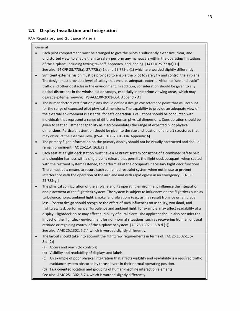
13
2.2 Display Installation and Integration
FAA Regulatory and Guidance Material
General • Each pilot compartment must be arranged to give the pilots a sufficiently extensive, clear, and
undistorted view, to enable them to safely perform any maneuvers within the operating limitations of the airplane, including taxiing takeoff, approach, and landing. [14 CFR 25.773(a)(1)]
See also: 14 CFR 23.773(a), 27.773(a)(1), and 29.773(a)(1) which are worded slightly differently. • Sufficient external vision must be provided to enable the pilot to safely fly and control the airplane.
The design must provide a level of safety that ensures adequate external vision to “see and avoid” traffic and other obstacles in the environment. In addition, consideration should be given to any optical distortions in the windshield or canopy, especially in the prime viewing areas, which may degrade external viewing. [PS-ACE100-2001-004, Appendix A]
• The human factors certification plans should define a design eye reference point that will account for the range of expected pilot physical dimensions. The capability to provide an adequate view of the external environment is essential for safe operation. Evaluations should be conducted with individuals that represent a range of different human physical dimensions. Consideration should be given to seat adjustment capability as it accommodates the range of expected pilot physical dimensions. Particular attention should be given to the size and location of aircraft structures that may obstruct the external view. [PS-ACE100-2001-004, Appendix A]
• The primary flight information on the primary display should not be visually obstructed and should remain prominent. [AC 25-11A, 16.b.(3)]
• Each seat at a flight deck station must have a restraint system consisting of a combined safety belt and shoulder harness with a single-point release that permits the flight deck occupant, when seated with the restraint system fastened, to perform all of the occupant's necessary flight deck functions. There must be a means to secure each combined restraint system when not in use to prevent interference with the operation of the airplane and with rapid egress in an emergency. [14 CFR 25.785(g)]
• The physical configuration of the airplane and its operating environment influence the integration and placement of the flightdeck system. The system is subject to influences on the flightdeck such as turbulence, noise, ambient light, smoke, and vibrations (e.g., as may result from ice or fan blade loss). System design should recognize the effect of such influences on usability, workload, and flightcrew task performance. Turbulence and ambient light, for example, may affect readability of a display. Flightdeck noise may affect audibility of aural alerts. The applicant should also consider the impact of the flightdeck environment for non-normal situations, such as recovering from an unusual attitude or regaining control of the airplane or system. [AC 25.1302-1, 5-8.d.(1)]
See also: AMC 25.1302, 5.7.4 which is worded slightly differently. • The layout should take into account the flightcrew requirements in terms of: [AC 25.1302-1, 5-
8.d.(2)] (a) Access and reach (to controls) (b) Visibility and readability of displays and labels. (c) An example of poor physical integration that affects visibility and readability is a required traffic
avoidance system obscured by thrust levers in their normal operating position. (d) Task-oriented location and grouping of human-machine interaction elements. See also: AMC 25.1302, 5.7.4 which is worded slightly differently.

14
Installation • Flight deck display equipment and installation designs should be compatible with the overall flight
deck design characteristics (such as flight deck size and shape, flightcrew member position, position of windows, external luminance, etc.) as well as the airplane environment (such as temperature, altitude, electromagnetic interference, and vibration). [AC 25-11A, 16.b.(1)]
• The installation of the display equipment must not adversely affect its readability and the external scene visibility of the flightcrew under all foreseeable conditions relative to the operating and lighting environment (§ 25.773 (a)(1)). [AC 25-11A, 16.b.(4)]
• If the display system design is dependent on cross-flight deck viewing for its use, the installation should take into account the viewing angle limitations of the display units, the size of the displayed information, and the distance of the display from each flightcrew member. [AC 25-11A, 16.b.(6)]
• When a display is used to align or overlay symbols with real-world external data (for example, HUD symbols), the display should be installed such that positioning accuracy of these symbols is maintained during all phases of flight. [AC 25-11A, 16.b.(7)]
• The display system components should not cause physical harm to the flightcrew under foreseeable conditions relative to the operating environment (for example, turbulence or emergency egress). [AC 25-11A, 16.b.(8)]
• The installed display must not visually obstruct other controls and instruments or prevent those controls and instruments from performing their intended function (§ 25.1301). [AC 25-11A, 16.b.(9)]
See also: Chapter 8 Intended Function • Radio and electronic equipment, controls, and wiring must be installed so that operation of any one
unit or system of units will not adversely affect the simultaneous operation of any other radio or electronic unit, or system of units, required by this chapter. [14 CFR 25.1431(c)]
See also: 14 CFR 23.1431(b), 29.1431(b) and AC 25-11A, 16.b.(10), which are worded slightly differently.
• For those airplanes required to have more than one flightcrew member, or whose operation will require more than one flightcrew member, the cockpit must be evaluated to determine if the flightcrew members, when seated at their duty station, can converse without difficulty under the actual cockpit noise conditions when the airplane is being operated. If the airplane design includes provision for the use of communication headsets, the evaluation must also consider conditions where headsets are being used. If the evaluation shows conditions under which it will be difficult to converse, an intercommunication system must be provided. [14 CFR 23.1431(c)]
• These evaluations need to be conducted to determine that communications between crew members can be adequately accomplished. Evaluations to determine compliance with this regulation are normally conducted during ground and flight tests under the highest expected noise conditions (e.g., high speed and full throttle). Crew members should be able to effectively communicate without excessive effort, e.g. shouting to be heard. It would be useful to analyze and identify potential noise sources early in the program. [PS-ACE100-2001-004, Appendix A]
• The display components should be installed in such a way that they retain mechanical integrity (secured in position) for all foreseeable conditions relative to the flight environment. [AC 25-11A, 16.b.(11)]
• Liquid spill on or breakage of a display system component in the flightdeck should not result in a hazard. [AC 25-11A, 16.b.(12)]

15
Vibration • The airplane must be demonstrated in flight to be free from any vibration and buffeting that would
prevent continued safe flight in any likely operating condition. [14 CFR 25.251(a)] • There must be no vibration or buffeting severe enough to result in structural damage, and each part
of the airplane must be free from excessive vibration, under any appropriate speed and power conditions up to VD/MD. In addition, there must be no buffeting in any normal flight condition severe enough to interfere with the satisfactory control of the airplane or cause excessive fatigue to the flight crew. Stall warning buffeting within these limits is allowable. [14 CFR 23.251]
See also: 14 CFR 25.251(b) – 25.251(d), 27.251, and 29.251 which are worded slightly differently. • Vibration and noise characteristics of cockpit equipment may not interfere with safe operation of
the airplane. [14 CFR 25.771(e)] See also: 14 CFR 27.771(c) and 29.771(c) which are worded slightly differently.
• Instrument panel vibration may not damage or impair the accuracy of any instrument. [14 CFR 23.1321(c), 25.1321(d), 27.1321(c), 29.1321(f)]
• The FAA Certification Team should ensure that the applicant has carefully considered the types and magnitudes of vibration and noise that may be present under both normal and abnormal conditions. Then, the tasks that may be affected by vibration (for example, display legibility and the operation of controls) and noise (for example, communication and identification of aural alerts) should be identified. Additionally, the methods that could be used to determine whether the vibration or noise will unacceptably interfere with safe operation of the airplane should be identified. [PS-ANM100-01-03A, Appendix A]
• When determining compliance, careful consideration should be given to the frequencies and magnitudes of the vibration, and the duration of exposure to these circumstances under normal conditions. Tasks that may be particularly affected by vibration include the capability to read displayed information and access or operate controls. Evaluations should be conducted to verify that any potential buffeting that could occur during normal flight conditions does not interfere with the pilot's capability to perform these tasks and satisfactorily control the airplane. If it is possible for the pilot to be exposed to the vibrations for extended periods, then evaluations should be made under worst case duration conditions to determine the effect on pilot fatigue. [PS-ACE100-2001-004, Appendix A]
Other Recommendation(s)
Installation • Cross cockpit viewing to the other pilot's displays should be provided to achieve the capability
dictated by certain failure conditions of critical functions. The off-axis angle is installation dependent and may exceed 50º from a normal to the display. Displays mounted on a center panel or center pedestal should be visible to both pilots. [SAE ARP1874, 5.1.2]
• The display surface should be perpendicular to the operator’s normal line of sight if feasible. The angle of incidence of the display surface should be between 45º and 90º relative to the pilot’s line of sight. (McAnulty, 1995; MIL-STD-1472G)
• For less critical displays, the preferred horizontal angle of regard is 35º, with a maximum of 60º. The preferred vertical angle of regard is 20º below or 40º above the pilot’s line of sight, with a maximum of 36º below or 66º above the pilot’s line of sight. (McAnulty, 1995)
• Any display that is not exactly replicated for both seats should be easily viewed from either seat without requiring major adjustments to body position. [Chandra, et al., 2003, 2.5.3]

16
• All displays necessary to support an user activity or sequence of activities shall be grouped together. [MIL-STD-1472G, 5.10.3.6.4.c.(8)]
Useful Screen • Equipment shall provide the maximum size active viewing area consistent with the limitations of unit
outline and required features (controls, handles, etc.). [SAE ARP1874, 5.1.1]
Background
Limited real estate has forced compromises when installing displays, and displays are sometimes placed outside the pilot’s normal viewing area. Additionally, cross-flight deck viewing is important so that the information can be shared by both pilots to facilitate crew coordination, since some display systems may not be replicated on the flight deck. In some cases, displays may not be accessible during the pilot’s normal visual scan, the information may not be readable when viewed off-angle, or colors may appear differently. (See Chapter 2.3 Field-of-View for more information.) An evaluation can be useful to determine whether the display accessibility and readability is affected by its placement. Limits in installation may need to be considered for particular display systems.
Airplane vibration during flight is a normal occurrence, but several studies and incidents have shown that the amplitude and frequency of the vibration can prevent pilots from seeing ahead out-the-window or reading their instruments. In 1991, a British Aerospace ATP aircraft encountered significant propeller icing while climbing, and this led to severe vibrations that made electronic flight instruments unreadable. Research experiments conducted after the incident showed that readability was negatively impacted at vibration frequencies in the range of 10 – 20 Hz (Viveash, et al., 1994). Thus, it is important to consider vibration during the design and evaluation process.
Example(s)
If the display glass is inset in a bezel, the bezel frame may obscure the edges of the drawing area when the display is viewed off-angle.
Some lines or fine details may disappear when displays are viewed off angle. For example, the ARTCC boundary, shown below, is composed of adjoining vertical and horizontal lines. On some displays, however, the vertical bars of the ARTCC boundary may disappear when viewed off-angle, so that the line pattern appears to be a series of horizontal lines.
ARTCC Boundary ARTCC Boundary Viewed Off Angle

17
2.3 Field-of-View
FAA Regulatory and Guidance Material
General • Each flight, navigation, and powerplant instrument for use by any pilot must be plainly visible to him
from his station with the minimum practicable deviation from his normal position and line of vision when he is looking forward along the flight path. [14 CFR 25.1321(a)] See also: 14 CFR 23.1321(a), 27.1321(a), and 29.1321(a) which are worded slightly differently.
• The instruments should be arranged for use by any pilot and must be readily visible to the pilot. Instrument location and arrangement, with respect to the pilot’s seat, should be designed to accommodate pilots from 5’2” to 6’0” in height. Pilots within this range should be able to see and, where necessary, reach and operate all of the displays. [AC 27-1B, AC 27.1321; AC 29-2C, AC 29.1321a]
• All displays shall be fully readable up to a horizontal viewing angle of 35 degrees from normal to the face of the display screen. [TSO-C146c/RTCA DO-229D, 2.2.1.1.4.3]
• They shall be fully readable up to a vertical viewing angle of 20 degrees from normal to the face of the display screen. [TSO-C146c/RTCA DO-229D, 2.2.1.1.4.3]
• This angle of regard does not ensure that the equipment may be installed in any aircraft; it is recommended that the angle of regard be maximized to increase the flexibility of the equipment for installation. [TSO-C146c/RTCA DO-229D, 2.2.1.1.4.3]
• If the aircraft is flying a vertical path (for example, VNAV path), then the deviation from that path should be displayed in the primary field of view, such as the PFD, navigation display (ND), or other acceptable display. [AC 25.1329-1B, 64.i.(1)(b)]
• All indicating means displayed (indicia, pointers, symbols, etc.) shall be completely visible from any eye position within the viewing envelope(s) as specified by the equipment manufacturer. Text and symbology shall be readily discernible and should be legible and readable within the specified viewing envelope(s). [TSO-C113a/SAE AS8034B, 4.2.1]
Note: It is the responsibility of the equipment installer to determine that the required aircraft viewing envelope is within the specified display viewing envelope(s). [TSO-C113a/SAE AS8034B, 4.2.1]
• The size of the viewing envelope should provide visibility of the flight deck displays over the flightcrew’s normal range of head motion, and support cross-flight deck viewing if necessary. [AC 25-11A, 16.a(12)]
• Displays should be located such that the pilot(s) can monitor them with minimal head and eye movement between displays. Flight information should be legible, accurate, easily interpreted, sufficiently free of visual cutoff (viewing angle), parallax and distortion, for the pilot to correctly interpret it. [AC 23.1311-1C, 14.1]
• The applicable flightcrew members, seated at their stations and using normal head movement, must be able to see and read display format features such as fonts, symbols, icons and markings so they can safely perform their tasks. In some cases, cross-flight-deck readability may be required to meet the intended function (§ 25.1301(a)) that both pilots must be able to access and read the display. [AC 25.1302-1, 5-5.b.(2)]
See also: AMC 25.1302, 5.4.2.c which is worded slightly differently; Chapter 3.4 Markings, Dials, Tapes, and Numeric Readouts; Chapter 8 Intended Function

18
• Readability must be maintained in sunlight viewing conditions per § 25.773(a) and under other adverse conditions such as vibration and turbulence. Figures and letters should not extend below the visual angles defined in SAE ARP 4102-7 at the design eye position of the flight crewmember who normally uses the information. [AC 25.1302-1, 5-5.b.(2)] See also: AMC 25.1302, 5.4.2.c which is worded slightly differently.
• Analysis of the angular offset of a display from the pilot’s centerline of vision may be necessary to determine how accessible that display is in a visual scan. Additionally, the visual angle subtended by the display may be used to determine how readable the display will be (apparent display size). Final assessment of the acceptability of the visibility of the instruments will require a geometrically correct mockup or the actual airplane. [PS-ACE100-2001-004, Appendix A]
• Line widths shall be of sufficient size and optimal sharpness to display the intended information with no distracting visual artifacts or ambiguities that could result in an unsafe condition. When viewed from within the design eye position viewing envelope (DEP-VE), lines of a specified color and luminance should appear uniform in width at all rotational or translational orientations of the line. Line width variation should not be readily apparent. Narrow or thin lines with a minimum line width less than 70% of the maximum line width, of that particular line, may produce an undesirable visual “roping” effect. [TSO-C113a/SAE AS8034B, 4.2.5]
• The design eye position is a single point selected by the applicant that meets the requirements of §§ 25.773(d) and 25.777(c) for each pilot station. Figure 1 depicts a design eye position and pilot compartment view for optimum collision avoidance potential for the left pilot seat. For the right pilot seat, all left/right dimensions are reversed. [AC 25.773-1, 4.b.]
• Position of displayed information: Distance from the design eye position (DEP) is generally used. If cross-flight deck viewing of the information is needed, distance from the offside design eye position (DEP), accounting for normal head movement, should be used. For displays not mounted on the front panel, the distance determination should include any expected movement away from the DEP by the flightcrew. [AC 25-11A, 31.a(2)]

19
Alerts and Annunciations See also: Chapter 4.1 Considerations for Alerting: General • In most applications, critical information that is considered to be essential for safe flight, with
warning or cautionary information that requires immediate pilot action or awareness, should be placed in the primary field-of-view. [AC 23.1311-1C, 15.2]
• Some annunciations may be acceptable within 35 degrees if they are associated with a unique aural tone or a master warning/caution annunciations that is within 15 degrees and with a pilot evaluation. [AC 23.1311-1C, 15.4, Note 4]
• Annunciations and indications should be consistently located in a specific area of the electronic display. Annunciations that may require immediate flightcrew awareness should be located in the flightcrew’s forward/primary field of view. [AC 25-11A, 31.f.(2)]
See also: AC 23.1311-1C, 18.1 which is worded slightly differently. • The visual-alert information should be located so that both pilots are able to readily identify the alert
condition. [AC 25.1322-1, Appendix 1, 2.a.(2)] • The horizontal (and vertical) deviation(s) display(s) and failure annunciations should be located
within the pilot's primary field of view, as should any indication requiring immediate aircrew action. [AC 20-138C, 11-8.b.(4)]
See also: AC 25-11A, 31.f.(2) and AC 23.1311-1C, 18.1 which are worded slightly differently; Chapter 4 Considerations for Alerting
• Displays used for waypoint sequencing, start of a turn, turn anticipation, active waypoint, distance to active waypoint, desired track and actual track (track angle error), and automatic mode switching should be located within the pilot’s primary field of view, or on a readily accessible display page. [AC 20-138C, 14-2.b]
See also: Chapter 2.2 Display Installation and Integration • Displays used for loss of integrity monitoring, TO/FROM indication, and approach mode
annunciation should be located within the pilot’s primary field of view. [AC 20-138C, 14-2.b.(1)] See also: Chapter 2.2 Display Installation and Integration • Traditionally, 14 CFR part 23 airplanes with “classic” analog instrumentation in the “basic T”
arrangement have included the center radio stack within the allowable field of view to satisfy this guidance. There is no intent for this AC to change that long-standing guidance. [AC 20-138C, 14-2.b.(2)]
• The alerting elements for time-critical warnings should include: [AC 25.1322-1, 6.b] - Unique voice information or unique tone, or both, for each alerting condition, and - Unique visual alert information in each pilot’s primary field of view for each alerting condition. • For example, unique visual alert information presented in each pilot’s primary field of view is
acceptable in place of a master visual alert if it provides immediate awareness and sufficient attention-getting characteristics. [AC 25.1322-1, 6.c]
• Master visual alerts for warnings (master warning) and cautions (master caution) should be located in each pilot’s primary field of view. [AC 25.1322-1, Appendix 1, 1.a]
• To determine the quantity of displays that provide warning, caution, and advisory alerts, take into account the combination of ergonomic, operational, and reliability criteria, as well as any physical space constraints in the flight deck. [AC 25.1322-1, Appendix 1, 2.a.(1)]
20
• All warning and caution visual information linked to a master visual alert should be grouped together on a single dedicated display area. There may be a separate area for each pilot. Advisory alerts should be presented on the same display area as warning and caution information. The intent is to provide an intuitive and consistent location for the display of information. [AC 25.1322-1, Appendix 1, 2.a.(3)]
• Time-Critical warning visual information should appear in each pilot’s primary field of view. [AC 25.1322-1, Appendix 1, 3.a]
Note: The primary flight display (PFD) is used as a practical and preferred display for displaying the time-critical warning alerts since the pilot constantly scans the PFD. Integrating time-critical information into the PFD depends on the exact nature of the warning. For example, a dedicated location on the PFD may be used both as an attention-getting function and a visual information display by displaying alerts such as “WINDSHEAR,” “SINK RATE,” “PULL UP,” “TERRAIN AHEAD,” and “CLIMB, CLIMB.” In addition, graphic displays of target pitch attitudes for Airborne Alert and Collision Avoidance System (ACAS) II Resolution Advisories and Terrain may also be included. [AC 25.1322-1, Appendix 1, 3.a]
• Information for error detection may …[be] indications provided to the flightcrew during normal monitoring tasks… Indications on instruments in the primary field of view used during normal operation may be adequate if the indications themselves contain information used on a regular basis and are provided in a readily accessible form. These may include mode annunciations and normal airplane state information such as altitude or heading. Other locations for the information may be appropriate depending on the flightcrew’s tasks, such as on the control-display unit when the task involves dealing with a flight plan. [AC 25.1302-1, 5-7.b.]
See also: AMC 25.1302, 5.6.2 which is worded slightly differently; Chapter 8 Intended Function Information to be Displayed in the Primary Field-of-View • Required engine indications necessary to set and monitor engine thrust or power should be
continuously displayed in the flightcrew’s primary field of view, unless the applicant can demonstrate that this is not necessary. The automatically selected display of powerplant information should not suppress other information that requires flightcrew awareness. [AC 25-11A, 36.b.(4)(a)] See also: Chapter 5.1 Basic “T” Arrangement
• The primary flight display of FPV/FPA symbology must not interfere with the display of attitude and there must always be attitude symbology at the top center of the pilot's primary field of view, as required by § 25.1321. [AC 25-11A, Appendix 1, 4]
• AC 23.1311-1C, Table 3 provides examples of information recommended for inclusion in this visual field. [See Examples section]
Required Navigation Performance (RNP) Approach - Performance and Functional Requirements • A non-numeric lateral deviation display (for example, CDI, EHSI), with a TO/FROM indication and a
failure annunciation, used as primary flight instruments for aircraft navigation, for maneuver anticipation, and for failure/status/integrity indication should have the following attributes: The display must be visible to the pilot and located in the primary field of view. [AC 20-138C, 8-3.g.(3)(a)]
• To be approved as an alternative means, the navigation map display must be shown to meet the TSE requirements and be located in the primary field of view. [AC 20-138C, 8-3.g.(3)(f)]
• The means to display the following items, either in the pilot’s primary field of view, or on a readily accessible display page: [AC 20-138C, 8-3.h.(6)]
(a) Distance between flight plan waypoints (b) Distance to go to the waypoint selected by the pilot

21
(c) Along track distances between waypoints (d) Active navigation sensor type (e) The identification of the active (To) waypoint (f) The ground speed or time to the active (To) waypoint; and, (g) The distance and bearing to the active (To) waypoint. • The capability to display an indication of the RNP system failure in the pilot’s primary field of view.
[AC 20-138C, 8-3.h.(11)] Required Navigation Performance (RNP) Terminal - System Performance Monitoring and Alerting • A non-numeric lateral deviation display (for example, CDI, EHSI), with a TO/FROM indication and a
failure annunciation, used as primary flight instruments for aircraft navigation, for maneuver anticipation, and for failure/status/integrity indication. [AC 20-138C, 9-3.g.(2)]
• To be approved as an alternative means, the navigation map display must be shown to meet the TSE requirements and be located in the primary field of view. [AC 20-138C, 9.3.g.(2)(f)]
• The means to display the following items, either in the pilot’s primary field of view, or on a readily accessible display page: [AC 20-138C, 9-3.h.(6)]
(a) The active navigation sensor type (b) The identification of the active (To) waypoint (c) The distance and bearing to the active (To) waypoint; and (d) The ground speed or time to the active (To) waypoint • The capability to display an indication of the RNP 1 system failure in the pilot’s primary field of view.
[AC 20-138C, 9-3.h.(14)] Barometric-Vertical Navigation (Baro-VNAV) Equipment Performance: Operations under IFR • Systems that provide steering signals for FDs or autopilots should provide automatic vertical
maneuver anticipation and a waypoint alert that occurs prior to the initiation of the vertical maneuver. Systems that are coupled to the automatic guidance/control system(s) should not cause the aircraft to depart an assigned altitude until the impending altitude change is indicated to the crew within the pilot’s primary field of view, then acknowledged by timely crew action. [AC 120-38C, 10-2.f.(7)(a)]
General Human Factors Considerations • Each display element, used as a primary flight instrument in the guidance and control of the aircraft,
should be located where it is clearly visible to the pilot with the least practicable deviation from the pilot’s normal position and line of vision when looking forward along the flight path. (Note 2: FTE can be reduced when numeric display information is integrated with the non-numeric display or is located within the pilot’s primary field of view.) [AC 20-138C, 11-8.b.(1)]
• The horizontal (and vertical) deviation(s), display(s), failure annunciations should be located within the pilot’s primary field of view, as should any indication requiring immediate aircrew action. [AC 20-138C, 11-8.b.(4)]
Global Navigation Satellite Systems (GNSS) • Displays used for waypoint sequencing, start of a turn, turn anticipation, active waypoint, distance to
active waypoint, desired track and actual track (track angle error), and automatic mode switching should be located within the pilot’s primary field of view, or, on a readily accessible display page. [AC 20-138C, 14-2.b.]
• Displays used for loss of integrity monitoring, TO/FROM indication, and approach mode annunciation should be located within the pilot’s primary field of view. [AC 20-138C, 14-2.b.(1)]

22
• For installations containing more than one approach navigation source, the navigation source (for example, ILS, GPS/SBAS, baro-VNAV, etc.) selected for the approach must be positively indicated in the primary field of view. Consideration should be given to the overall aircraft-level annunciation philosophy. [AC 20-138C, 14-6.6.a.]
• The approach type (LP/LPV, LNAV/VNAV, LNAV) must be clearly annunciated to the pilot prior to and throughout the entire approach in the primary field of view. [AC 20-138C, 14-6.6.b]
• There must be an unambiguous indication the navigation source is provided by GPS/SBAS, GPS/GBAS, or ILS, as appropriate, in the primary field of view. [AC 20-138C, 14-6.6.b(1); 14-6.6.b(2)]
• For installations containing more than one approach navigation source, the navigation source (for example, ILS, GPS/GBAS, etc.) selected for the approach must be positively indicated in the primary field of view. [AC 20-138C, 14-8.8.a.]
• The approach type (GLS) must be clearly annunciated to the flight crew prior to and throughout the entire approach in the primary field of view (GLS). [AC 20-138C, 14-8.8.b]
• There must be an unambiguous indication the navigation source is provided by GPS/SBAS, GPS/GBAS, or ILS as appropriate in the primary field of view. [AC 20-138C, 14-8.8.b(1); 14-8.8.b.(2)]
Area Navigation (RNAV) Multi-Sensor Equipment • The distance to the active waypoint must be displayed either in the pilot’s primary field of view or on
a readily accessible display page unless there are alternate means to indicate waypoint passage. [AC 20-138C, 15-2.1.b(1)]
• Multi-sensor equipment may drive remote annunciators in the primary field of view. [AC 20-138C, 15-3]
• Waypoint sequencing, start of a turn, turn anticipation, TO/FROM indication, approach mode annunciation, and automatic mode switching should be located within the pilot’s primary field of view, or, on a readily accessible display page. [AC 20-138C, 15-3.c]
• The multi-sensor equipment should provide annunciations for loss of integrity monitoring, loss of navigation, TO/FROM indication, and approach mode annunciation within the primary field of view. [AC 20-138C, 15-3.d]
Integration with GNSS-Provided Vertical Guidance • There should be an annunciation in the primary field of view indicating the active approach type (for
example, GLS, LPV, LP, LNAV/VNAV, LNAV). The intent is to ensure the crew has an unambiguous indication of the active approach in the primary field of view that will correlate to a line of minima on the approach chart. [AC 20-138C, 17-5.a.7]
Installation Considerations for RNP Authorization Required (AR) • The aircraft manufacturer should also verify that a visual alert within the flight crew’s primary field
of view occurs with a loss of navigation capability and/or loss of RNP containment integrity. An aural alert should accompany the visual alert. [AC 20-138C, Appendix 2, A2-8.b]
RNP Advanced Features • The applicant should verify that a visible alert occurs within the flightcrew’s primary field of view
when loss of navigation capability and/or loss of integrity are experienced. [AC 20-138C, Appendix 3, A3-2 a.(5)]
• The instruments necessary for safe operation (e.g., airspeed indicator, gyroscopic direction indicator, gyroscopic bank-and-pitch indicator, slip-skid indicator, altimeter, rate-of-climb indicator, master caution or warning (if installed), rotor tachometers, and the indicator most representative of engine
power) should be installed immediately in front of pilots in their primary field of view (FOV). [AC 29.1321, b.(1)]

23
• Display high priority information in the primary FOV as well as the primary flight information. [AC 29.1321, b.(1)(i)]
Information to be Displayed in the Primary Optimum Field-of-View Required Navigation Performance (RNP) Authorization Required (AR) General Requirements • The aircraft should have an appropriately-scaled, non-numeric deviation display (i.e., lateral
deviation indicator and vertical deviation indicator) in the pilot’s primary optimum field of view. [AC 20-138C, A2-3.d.(1)(b)]
• In lieu of appropriately scaled lateral and vertical deviation indicators in the pilot’s primary optimum field of view, a numeric display of deviation may be acceptable depending on the flight crew workload and the numeric display characteristics. [AC 20-138C, A2-3.d.(1)(c)]
• The navigation system must provide a display identifying the active waypoint either in the pilot’s primary optimum field of view, or on a readily accessible and visible display to the flight crew. [AC 20-138C, A2-3.d.(2)]
• The navigation system must provide a display of distance and bearing to the active (TO) waypoint in the pilot’s primary optimum field of view. Where not viable, a readily accessible page on a control display unit, readily visible to the flight crew, may display the data. [AC 20-138C, A2-3.d.(3)]
• The navigation system must provide the display of groundspeed and time to the active (TO) waypoint in the pilot’s primary optimum field of view. Where not viable, a readily accessible page on a control display unit, readily visible to the flight crew, may display the data. [AC 20-138C, A2-3.d.(4)]
• The navigation system must provide a TO/FROM display in the pilot’s primary optimum field of view. [AC 20-138C, A2-3.d.(5)]
• The navigation system must provide a display of the actual aircraft track (or track angle error) either in the pilot’s primary optimum field of view or on a readily accessible and visible display to the flight crew. [AC 20-138C, A2-3.d.(7)]
• The aircraft must provide a means to annunciate failures of any aircraft component of the RNAV system, including the navigation sensors. The annunciation must be visible to the pilot and located in the primary optimum field of view. [AC 20-138C, A2-3.d.(8)]
• The aircraft must display barometric altitude from two independent altimetry sources, one in each pilots’ primary optimum field of view to support an operational cross check of altitude sources. (Note 1: If the aircraft includes the ability to automatically compare the output of the independent altitude sources, including independent aircraft static air pressure systems, and the aircraft can provide an alert in the pilot’s primary optimum field of view when deviations between the sources exceed +/-100 feet, then the applicant should document this comparator monitoring function in the AFM/RFM or aircraft qualification guidance.) [AC 20-138C, A2-3.d.(14)]
• The aircraft must display the current navigation sensor(s) in use. The aircraft should provide this display in the primary optimum field of view. [AC 20-138C, A2-3.d.(15)]
Reversionary Flight Displays Instead of Standby Instruments or Dual PFDs • The PFI should be presented in similar format and sufficient size in the reversionary mode as it is in
normal mode to allow the pilot to enhance the control of the airplane. This reversionary configuration should provide backup information essential to continued safe flight and landing with an intuitive control that allows instant, simultaneous access to reversionary mode on both the PFD and MFD displays. The single pilot action should be easily recognized, readily accessible, and have

24
the control within the pilot’s primary optimum field of view. An acceptable method for the single pilot action is the red color and/or lighted red “halo” ring that announces its position on the panel at all times. [AC 23.1311-1C, 8.4.1.d]
• If an aircraft is equipped with multiple AHRS, it may be acceptable, when one AHRS fails, to drive both the autopilot and the PFD from a single AHRS as long as an AHRS independent attitude display (required for some aircraft classes) is located in the primary maximum field of view. [AC 23.1311-1C, 8.3.2]
Information to be Displayed in the Secondary Field-of-View • Signals and information pilots scan as part of monitoring the aircraft and its performance are located
in the secondary FOV. The secondary FOV is bound laterally to minimize the need for pilots to turn their heads to view the information. Examples of information typically located in the secondary FOV are: [AC 29.1321, b.(1)(ii)]
(A) Ancillary navigation information (moving maps, weather displays, etc). (B) Secondary powerplant information like engine oil pressures and temperatures. (C) Caution advisory and warning system (CAWS) panel (if a master caution or warning indicator is
located in the primary FOV, otherwise the CAWS panel should be as close to the pilots primary FOV as possible).
(D) Autopilot. (E) Navigation controls. Rotorcraft Operations • Nonprecipitation Conditions. [AC 29-2C, AC 29.773a] (1) Explanation. (i) The procedures paragraph following this explanation discusses one means of demonstrating
an adequate field of view. (ii) Since glare and reflection often differ with the sun’s inclination, consideration should be
given to evaluating the cockpit at midday and in early morning or late afternoon. Windshields with embedded wire heating elements should be evaluated for distortion with the system both “ON” and “OFF.”
(iii) If night approval is requested, all lighting, both internal and external, should be evaluated in likely combinations and under expected flight conditions. Although a certain amount of equipment reflection (avionics control heads, etc.) in the windscreen may be unavoidable, the pilot’s normal field of view should be unobstructed. Windshield reflections often dictate large glareshields which result in reduction of the optimum field of view. This problem is most apparent in IFR equipped aircraft (having larger instrument panels and avionic consoles) which are operated in VFR utility roles. Landing and taxi lights should be exercised throughout their adjustment range (if applicable) to check for reflections, particularly in chin windows. Anticollision and strobe lights should be evaluated to ensure that frequency interaction and reflections off the rotor do not result in distractions to the pilot. The effect of cabin lighting on the pilot compartment view should be assessed, particularly on EMS configured aircraft where the in-flight use of cabin lights may be mandatory.
(2) Procedures. The following procedures are one acceptable means of evaluating pilot compartment field of view considering only those objects in the pilot compartment, the windshield, and its support structure in nonprecipitating conditions. The applicant’s design is not required to meet these guidelines, and each design should be evaluated on its own merits.

25
The area of visibility established in the following paragraphs will provide an acceptable level of visibility for a minimum crew of one (pilot). In the event that a minimum crew of two (pilot and copilot) is required, the second pilot should have an area of visibility equivalent to that provided for the pilot but on the opposite side. In this event, the pilot’s area of visibility to the left as shown in figure AC 29.733-1 needs only to comply to 60° left, and the area of visibility for the second pilot needs only to comply to 60° right.
(i) A single point established in accordance with the provisions of this paragraph constitutes the referenced eye position (i.e., a point midway between the two eyes) from which the central axis may be located. The referenced eye position is a reference datum point based on the eye location that permits the specified vision envelope required by figure AC 29.733-1, allows for posture slouch, and is the datum point from which the aircrew station geometry is constructed. The referenced eye position should be located by means of ship’s coordinates that contain station reference number, water line, and butt line for both pilot and copilot, if applicable, and complies with:
(A) The pilot’s seat in a normal operating position from which all controls can be utilized to their full travel, by an average subject, and which should provide for vertical adjustment of the seat of not less than 2.5 inches above and 2.5 inches below this initial vertical position.
(B) The seat back in its most upright position. (C) The seat cushion depression being that caused by a subject weighing 170 to 200
pounds. (D) The longitudinal axis of the rotorcraft to be that of “cruise attitude” (0.9VH or 0.9 VNE
whichever is lower). (E) The point established not beyond 1 inch to the right or left of the longitudinal
centerline of the pilot’s seat. (F) All measurements made from the single point established in accordance with this
paragraph. (ii) A dual lens camera, as photo recorder, should be used in measuring the angles specified in
the paragraphs listed below. Other methods, including the use of a goniometer, are acceptable if they produce equivalent areas to those obtained with a dual lens camera. When not using a dual lens camera, compensation should be made for one-half the distance which exists between the eyes, or 1¼ inches. With the referenced eye position located as indicated in paragraph AC 29.733a(2)(i), and utilizing binocular vision and azimuthal movement of the head and eyes about a radius, the center of which is 3 and 5/16 inches behind the referenced position (this point to be known as the central axis), the pilot should have the following minimum areas of vision measured from the appropriate eye position. (See figure AC 29.733-1.)
(A) 20° forward and above the horizon between 0° and 100° left. (B) 20° forward and below the horizon between 10° and 100° left. (C) 20° forward and below the horizon at 10° left increasing to a point 30° forward and
below the horizon at 10° right. (D) 50° forward and below the horizon between 10° right and 135° right. (E) 20° forward and above the horizon at 0° increasing to a point 40° above the horizon at
80° right and 100° right and then decreasing to a point 20° forward and above the horizon at 135° right.

26
(iii) Any vertical obstruction which falls within the minimum area of visibility outlined in paragraph AC 29.733a(2)(ii) should be governed by the following:
(A) No vertical obstruction between 20° right and 20° left. (B) Between 20° right and 135° right, vertical obstruction should not exceed 2.5 inches in
width. (C) Between 20° left and 100° left no vertical obstruction greater than 2.5 inches in width. (iv) Any horizontal obstruction which falls within the minimum area of visibility outlined in
paragraph AC 29.733a(2)(ii) should be governed by the following: (A) The area 15° forward and above the horizon between 135° right and 40° left
decreasing to a point 10° above the horizon at 100° left, and 15° forward and below the horizon between 135° right and 100° left should be free from horizontal obstructions.
(B) The area above and below the horizon which is between the minimum area of vision specified in paragraph AC 29.733a(2)(ii) and paragraph AC 29.733a(2)(iv)(A) is limited to one horizontal obstruction above the horizon, and one below the horizon. These horizontal obstructions should not be greater than 4 inches in width. An overhead window which will provide twice as much additional visibility as was lost due to the obstruction, should be located immediately above any obstruction which is above the horizon. This requirement is in addition to any area of visibility specified by paragraph AC 29.733a(2)(ii) which may be included in the overhead window area.
(C) If the instrument panel obstructs any required area between 10° left and 10° right below 20° forward and below the horizon, a window which affords triple equivalent additional visibility should be located immediately below and between the angles of 20° left and 20° right above 65° below the horizon.
(v) For steep rejected takeoffs and steep approaches such as used for oil rigs or confined heliports, the visibility should be such that the pilot can see the touchdown pad and sufficient additional area to the side and forward to provide both an accurate approach to the touchdown point as well as a satisfactory degree of depth perception. A 5-inch head movement, by the pilot, forward and/or sideward of the normal position is acceptable in determining compliance.
• Precipitation Conditions [AC 29-2C, AC 29.773b] (1) Explanation. (i) Heavy rainfall is defined by the National Weather Service as one resulting in accumulation
in excess of 0.03 inches in 6 minutes. On past designs, the windshield wipers required by § 29.1307 have been adequate to ensure satisfactory view at low to medium airspeeds. Airflow over the windshield and/or wipers has normally been sufficient to keep the windshield clear at higher airspeeds. Obscuration of side windows by rainfall should be addressed, particularly for confined area approaches.
(ii) If icing certification is requested, a means must be provided to ensure that a sufficiently large viewing area is kept clear of ice to permit safe operation. As a minimum, a clear area on the windshield should be available, although some configurations could require clear view in other areas, in order to provide an adequate level of safety in certain operations.
(iii) An openable “clear view” window must be provided for the first pilot. The rule requires that the window be openable in heavy rain at forward speeds to VH and in the worst icing conditions requested for certification. The rule further requires a field of view through this opening which is adequate for safe operation. Although the rule implies that a safe field of

27
view must be provided for airspeeds up to VH, it has not been interpreted as such. In most designs, the only practical location for an openable window is in a side panel or door. Aircraft sideslip limits normally restrict useful view from this window opening at high airspeeds. The intent is to provide the pilot with an adequate view for safe approach and landing in the event that normal windshield clearing systems malfunction.
(2) Procedures. Compliance with the requirements of this rule should be checked by flying the aircraft in the applicable environmental conditions. Although wipers can be partially checked on the ground with a hose, their effectiveness at higher airspeeds should also be verified. Likewise, additional or alternate rain removal systems should be exercised throughout the required airspeed range. The need for windshield wash systems should be assessed, particularly if the aircraft will be used in an offshore salt spray environment. Systems provided to ensure clear view in icing conditions should be evaluated during icing flight tests. The location and effectiveness of the openable window should be evaluated following failure of the rain removal and anti-ice system (if applicable). The view through the window opening should permit safe operation from hover up to a reasonable approach airspeed. Care should be exercised during flight test to stay within airframe sideslip limits.
Other Recommendation(s)
General • The nominal viewing distance should be 29 in (737 mm) from the pilot’s design eye point. Critical
displays in the pilot’s field-of-view should have a minimum viewing distance of 10 in (254 mm); less critical displays may have a minimum viewing distance of 13 in (330 mm). The maximum viewing distance should be 40 in (1,016 mm). (McAnulty, 1995)
• All indicating means (indicia, pointers, symbols, etc.) on the useful display surface shall be completely visible from any eye position within the instrument's viewing envelope as specified by the equipment manufacturer. Each installation should be examined to insure that the design eye position is within the instrument's viewing envelope. The examination may be a combination of test, analysis, simulation or flight test. [SAE ARP1874, 5.1.2]
Alerts and Annunciations • Visual alerts shall be presented in a consistent location in the forward field of view. [RTCA DO-256,
2.1.6] • High priority alarms should be placed in the pilot’s primary field-of-view. If all critical alerts cannot
be placed within 15 degrees, a master warning display is also appropriate. [GAMA Publication No. 10, 7.1.5.1]
• Visual warnings must be placed in the primary field-of-view. [GAMA Publication No. 10, 7.1.7.1] • A visual enunciation of warnings and cautions should be displayed within the pilot’s primary field of
view, always located in the same position on a manufacturer’s product. Separate and discrete enunciators for warnings and cautions should be integrated into a single display. If the CAS does not present required warnings or cautions in the pilot’s primary field of view, a master warning/caution annunciation (aural and visual, if applicable) shall be provided. Visual indication of master warning/caution shall be located within the pilot’s primary field of view. [GAMA Publication No. 12, 11.1]
28
Information to be Displayed in the Primary Field-of-View • Critical or frequently used displays shall be located in the central visual field… and occupy a
privileged position in that field (e.g., the top or left-most position). [Ahlstrom and Longo, 2003, 5.1.2.10]
• Indicators for critical functions shall be located within 15° of the user's normal line of sight [Ahlstrom and Longo, 2003, 6.2.2.1.8]
• Displays used most frequently shall be grouped together and placed in the optimum visual zone. [MIL-STD-1472G, 5.2.2.2.5.b]
• For critical functions as defined by the task analysis, indicators shall be located within 15 degrees of the user’s normal line of sight. Warning lights shall be an integral part of, or located adjacent to, the lever, switch, or other control by which the user is to take action. [MIL-STD-1472G, 5.2.3.13.11]
• Hardware input controls should be placed in the cockpit and arranged in a consistent manner to allow ease of use by the pilot. The criticality of the function being controlled must also be considered in determining the position of the control in the cockpit/flight deck. The location of navigation controls becomes very important if the navigation systems are used during critical phases of flight…Functions that need to be used in higher workload phases of flight, e.g. approach, need to be located in the primary FOV. [GAMA Publication No. 10, 7.1.2.5]
• By examination or analysis, determine that navigation system inputs and navigation display parameters of commands and path deviation are located in the primary field-of-view. Other non-flight critical navigation information may be displayed in secondary-field-of-view. For example, a CDU that is not the sole or primary device being used to display dynamic position data used directly to fly the aircraft to maintain a navigation path may be in the secondary field-of-view, pedestal or side console areas and may display such data itself. [GAMA Publication No. 10, 7.1.4.6]
• Critical functions will be in the pilot’s primary field-of-view with longitudinal awareness, lateral/vertical awareness and height awareness display symbols on horizontal line in front of the pilot using the information. [GAMA Publication No. 10, 7.1.4.7]
• Validate that attitude, altitude, airspeed and basic level of navigation (including heading) is within the pilot’s primary field-of-view (FOV) as determined through visual field modeling in a three-dimensional electronic cockpit mockup, measurement in a development fixture or other mockup, or measurement on engineering drawings. Regardless of the specific implementation or parameter used, critical data and information should be displayed in the primary FOV. [GAMA Publication No. 10, 7.1.4.7]
• By examination or analysis determine that critical reversionary display functions are in the pilot’s primary or secondary field-of-view from that pilot position. [GAMA Publication No. 10, 7.1.4.8]
• At a minimum, the primary navigation information must be in the primary field of view and shall include: [GAMA Publication No. 12, 6.1.2.1]
6.1.2.1.1 A Horizontal Situation Indicator (HSI). The HSI shall be capable of displaying vertical deviation and a digital distance indication to/from the selected fix. The HSI should provide arc and/or 360° moving-map modes. (Reference RTCA DO-257∗)
6.1.2.1.2 ‘TO’ and ‘FROM’ Indication. The TO indication will be situated between the airplane symbol and the head of the course indicator. The FROM indication will be situated between the airplane symbol and the tail of the course indicator. The TO/FROM indication should be visible in both a 360° mode and an arc display.
∗ Note the source text references RTCA DO-257 and RTCA DO-229C, however those documents have been revised.
29
6.1.2.1.3 Display Status. The approach, terminal, enroute, Course Deviation Indicator (CDI) scale or RNP status when displayed as prescribed by DO-229C shall be in the same location on a supplier’s product, labeled with the correct abbreviation. (Reference RTCA DO-229C*)
6.1.2.1.4 Course Deviation Indicator. When CDI scaling value is displayed, it shall be in nautical miles and the indication shall be adjacent to the CDI.
6.1.2.1.5 Display of Navigation Sources. The navigation source commanding the lateral deviation bar or bearing indicators shall be labeled in a prominent and unambiguous manner and located adjacent to the HSI. This information will be provided to the pilot in the same location on a supplier’s product, using the correct abbreviations. (Reference 14 CFR parts 23.1329, 23.1335, 23.1311).
6.1.2.1.5.1 Navigation-Source Labels. If installed, the following labels should be used to indicate navigation sources:
VOR1, VOR2 ADF1, ADF2 LOC1, LOC2 GPS1, GPS2 FMS1, FMS2 LRN1, LRN2 NAV1, NAV2 • When any portion or axis of the autopilot system is engaged to the airplane flight controls, an
annunciation that the autopilot is engaged must always be displayed in the pilot’s primary field of view. [GAMA Publication No. 12, A.3.2.1]
• High priority alarms should be placed in the pilot’s primary field-of-view. If all critical alerts cannot be placed within 15 degrees, a master warning display is also appropriate. [GAMA Publication No. 10, 7.1.5.1]
• The most critical displays and their controls are located in the primary field-of-view. [GAMA Publication No. 10, 7.1.7.1]
Information to be Displayed in the Secondary Field-of-View • Under failure conditions reversionary data in the Basic-T may be in the pilot’s secondary field-of-
view. [GAMA Publication No. 10, 7.1.4.8] • The next most critical displays and their controls are located in the secondary field-of-view. [GAMA
Publication No. 10, 7.1.7.1] • Current surface trim position indication may be displayed to the pilot in the secondary field-of-view.
[GAMA Publication No. 10, 7.1.8.2]
Background
A variety of terms are used in regulatory and guidance material to refer to the “primary field-of-view”, including “primary field-of-view”, “primary optimum field-of-view”, and “primary maximum field-of-view”. The FAA is moving towards use of the term “primary field-of-view”. A list of terms currently used and the definitions provided from FAA regulatory and guidance material are included in Table 2.3.1 in the Examples section. FAA regulatory and guidance material generally bases the pilot’s primary field-of-view on “the optimum vertical and horizontal visual fields from the design eye reference point that can be accommodated with eye rotation only. With the normal line-of-sight established at 15 degrees below the horizontal plane, the values for the vertical (relative to normal line-of-sight forward of the aircraft) are +/-15 degrees optimum, with +40 degrees up and -20 degrees down maximum. For the horizontal visual field (relative to normal line-of-

30
sight forward of the aircraft), the values are +/-15 degrees optimum, and +/-35 degrees maximum.” (See AC 25.1322-1.) This region is depicted below.
Figure 1. Primary Field-of-View. Image excerpted from AC 25.1322-1, Appendix 5.
The description of primary field-of-view used in human factors research reports generally define it as a region with a 15 degree radius extending from the normal line of sight; the normal line of sight is established as 15 degrees below a line extending horizontally from the eye (e.g., Ahlstrom and Longo, 2003; Cardosi and Huntley, 1993; Cardosi and Murphy, 1995; MIL-STD-1472G). Some documents also refer to this region as the primary optimum field-of-view and describe a primary maximum field-of-view that is +/-35 degrees horizontal, and +40 degrees up and -20 degrees down. This description is identical to that used in FAA regulatory and guidance material and depicted in Figure 1 Primary Field-of-View (Ahlstrom and Longo, 2003; MIL-STD-1472G). Finally, other documents define a region within 30 degrees of the normal line of sight and allow caution signals or other secondary signals to be presented within that region (Veitengruber, 1979). A list of definitions excerpted from key human factors research reports are presented in Table 2.3.2 in the Examples section.
The regions that comprise the primary field-of-view correspond to the area of the visual field with the highest visual acuity. This is the part of the eye with the highest density of visual receptor cells and thus, the best visual acuity and detailed vision. (The density of receptor cells decreases from the center of the eye towards the periphery, so visual acuity decreases correspondingly as well.) Information placed outside the primary field-of-view may not be detected as quickly. Thus, critical information considered necessary for safe flight or that requires immediate pilot action or awareness is generally presented in this central location (Boucek, Veitengruber., and Smith, 1977; Cardosi and Huntley, 1993; Cardosi and Murphy, 1995; Veitengruber, Boucek, and Smith, 1977).
The distance from the design eye position (DEP) is typically used to evaluate the visibility and readability of information on the flight deck. AC 25-11A defines the DEP as:
“the position at each pilot's station from which a seated pilot achieves the required combination of outside visibility and instrument scan. The DEP is a single point selected by the applicant that meets the requirements of §§ 25.773(d), 25.777(c), and 25.1321 for each pilot station. It is normally a point fixed in

31
relation to the aircraft structure (neutral seat reference point) at which the midpoint of the pilot's eyes should be located when seated at the normal position. The DEP is the principal dimensional reference point for the location of flight deck panels, controls, displays, and external vision” (see AC 25-11A, Appendix 3).
AC 25-11A contains a requirement for measuring viewing distance to flight deck instruments using the DEP (see AC 25-11A, Section 31.a.(2)). However, AC 23.1311-1C notes that “Part 23 rules do not require the applicant to establish a cockpit design eye reference point from which to measure viewing distances and angular displacement to various cockpit equipment” [AC 23.1311-1C, 15.1]. If an applicant intends to seek display approval for a specific system across for multiple types of aircraft (e.g., parts 23, 25, 27, 29), it may be worthwhile for that applicant to comply with to the most stringent requirements for any given regulation or related regulatory and guidance material, which in this case would be the part 25 guidance.
The flight deck of some rotorcraft may not allow for the same types of display configurations as on fixed wing aircraft. Specifically, AC 29-2C, Certification of Transport Category Rotorcraft, provides different field-of-view requirements from those specified for aircraft to accommodate a wider range of flight deck designs (note that AC 27-1B (Change 3), Certification of Normal Category Rotorcraft, contains related policy, which is worded differently). Thus, text excerpted from AC 29-2C, AC 29.773, is provided to detail the field-of-view requirements for transport category rotorcraft.
Example(s)
Alerts located on displays outside the pilot’s primary field-of-view may be missed. In an examination of problems associated with the use of LORAN-C/GPS receivers, pilots reported that they sometimes took up to four minutes to notice and respond to an alert, which may not have been indicated in the primary field-of-view. The alerts included red and yellow warning lights, blinking, and freezing the information on the display. Annunciator panels that display all the warning, caution, and advisory information on the flight deck can be used so that pilots can see at a glance which system malfunctioned or failed (Adams, et al., 1993).
The following two tables list the terms and definitions used to refer to the primary field-of-view from FAA regulatory and guidance material (Table 2.3.1) and from human factors research reports and guidance documents (Table 2.3.2).
Table 2.3.1. Primary field-of-view. The definitions were excerpted from the source material.
FAA Regulatory and Guidance Material
Term Definition (Excerpted from FAA Regulatory and Guidance Material)
AC 20-138C, Airworthiness Approval of Positioning and Navigation Systems
Primary field of view
The vertical and horizontal visual fields relative to the design eye reference point that can be viewed with eye rotation only using foveal or central vision. The values for the horizontal (relative to the normal line of sight) are +/-15 degrees optimum, with +/- 35 degrees maximum. The values for the vertical (relative to normal line of sight) are +/-15 degrees optimum, with + 40 degrees up and -20 degrees down maximum (see AC 25-11 latest revision). The primary field of view definition should be broad enough to include the center radio stack on 14 CFR part 23 airplanes with “classic”, analog basic ‘T’ instrumentation. For rotorcraft, reference the visibility requirements defined in the latest revisions of AC 27-1 and 29-2. [Appendix 7-1.r.]
Primary Optimum Field of View
For the purpose of this AC related to RNP AR, the primary optimum field of view is within +/-15 degrees horizontal and vertical relative to the pilot’s normal line of sight. [Appendix 7-1.s.]
AC 23.1311 – 1C, Field-of-view The angular extent of the display that can be seen by either pilot with

32
FAA Regulatory and Guidance Material
Term Definition (Excerpted from FAA Regulatory and Guidance Material)
Installation of Electronic Display in Part 23 Airplanes
the pilot seated at the pilot’s station. [6.2.p] Part 23 rules do not require the applicant to establish a cockpit design eye reference point from which to measure viewing distances and angular displacement to various cockpit equipment. [15.1]
Primary optimum field-of-view
Primary optimum field-of-view is based on the vertical and horizontal visual fields from the design eye reference point that can be accommodated with eye rotation only. With the normal line-of-sight established at 15 degrees below the horizontal plane, the values for the vertical and horizontal (relative to normal line-of-sight forward of the aircraft) are +/-15 degrees. This area is normally reserved for primary flight information and high priority alerts. [Section 15.2] Image in Figure 1 included.
Primary maximum field-of-view
Primary maximum field-of-view is based on the vertical and horizontal visual fields from the design eye reference point that can be accommodated with eye rotation and minimal head rotation. These values are +/-35 degrees horizontal, and +40 degrees up and -20 degrees down vertical. These areas are normally used for important and frequently used information. A pilot’s visual scan and head rotation is minimized when information is placed in this area. Placement of information in this area also reduces the potential for spatial disorientation. [Section 15.3] Image in Figure 1 included.
AC 25-11A, Electronic Flight Deck Displays
Primary field of view
Primary Field-of-View is based on the optimum vertical and horizontal visual fields from the design eye reference point that can be viewed with eye rotation only using foveal or central vision. The description below provides an example of how this may apply to head-down displays. With the normal line-of-sight established at 15 degrees below the horizontal plane, the values for the vertical (relative to normal line-of-sight forward of the aircraft) are +/-15 degrees optimum, with +40 degrees up and -20 degrees down maximum. [Section A3-9] Image in Figure 1 included.
AC 25.1322-1, Flightcrew Alerting
Primary field of view
Primary Field of View is based upon the optimum vertical and horizontal visual fields from the design eye reference point that can be accommodated with eye rotation only. The description below provides an example of how this may apply to head-down displays. With the normal line-of-sight established at 15 degrees below the horizontal plane, the values for the vertical (relative to normal line-of-sight forward of the aircraft) are +/-15 degrees optimum, with +40 degrees up and -20 degrees down maximum. For the horizontal visual field (relative to normal line-of-sight forward of the aircraft), the values are +/-15 degrees optimum, and +/-35 degrees maximum. [In Definitions section] Image in Figure 1 included.

33
Table 2.3.2. Field-of-view terms as defined and/or used in human factors research reports and guidance documents.
Document Term Definition (Excerpted from Document) Human Factors Design Standard. Ahlstrom and Longo, 2003
Optimum vertical and horizontal visual fields
The following figures are used to define the optimum vertical and horizontal visual fields. No text definition is provided
----------------------------------------------------------------------------
----------------------------------------------------------------------------
[See Section 5.1.2.10 or Section 6.2.2.1.8]
Central visual field Central visual field (sometimes referred to as the focal area) is the central 30° of the visual field. This is the area that people use to look at objects in the world, moving their eyes as needed to bring images of the object onto the fovea, which is the area of highest acuity. When an object is outside of the focal area, a person will usually turn their head rather than simply move their eyes. [5.1.2.10]
Human Factors for Flight Deck Certification Personnel. Cardosi and Huntley, 1993
N/A As a practical matter, one can now see why FAA guidelines stress the importance of placing master visual alerts within 15º of each pilot’s normal line of sight as illustrated [in the figure below]. This is the area of the visual field with best visual acuity and typically the center of attention. [Page 21]

34
Document Term Definition (Excerpted from Document) Human Factors in the Design and Evaluation of Air Traffic Control Systems. Cardosi and Murphy, 1995
N/A This optimal area can be thought of as a cone extending from the normal line of sight with a radius of 15 degrees. (The normal line of sight is the line 15 degrees below the line extending horizontally from the center of the pupil.) [Section 7.2.11]
MIL-STD-1472G Field-of-view The area that is visible for viewing only through eye and head movement. [3.3.13]
Optimum visual zone The optimum vertical and horizontal visual fields are defined using the same figure shown in the Human Factors Design Standard.
GAMA Publication No. 10 Recommended Practices and Guidelines for Part 23 Cockpit/Flight Deck Design, 2000
Primary Field-of-View Primary Field-of-View is based upon the optimum vertical and horizontal visual fields from the design eye reference point that can be accommodated with eye rotation only. With the normal line-of-sight established at 15 degrees below the horizontal plane, the values for the vertical (relative to normal line-of-sight forward of the aircraft) are +/-15 degrees optimum, with +40 degrees up and -20 degrees down maximum. For the horizontal visual field (relative to normal line-of-sight forward of the aircraft), the values are +/-15 degrees optimum, and +/- 35 degrees maximum. Image in Figure 1 included.
Secondary Field-of- View
Secondary Field-of-View is based upon the optimum horizontal and vertical visual fields from the design eye reference point that can be accommodated with head rotation. These values are +/- 60 degrees horizontal and + 65 and - 35 degrees vertical. These values are established from the normal line of sight and illustrated in Figure 3.2. The Secondary Field-of-View range defines the ability of the pilot to observe the operation and to use the critical parameters of a system without inducing disorientation or undue body movement.
GAMA Publication No. 12 Recommended Practices and Guidelines for an Integrated Cockpit/Flightdeck in a CFR Part 23 Certificated Airplane, 2005
Primary field of view No definition provided.
RTCA DO-256, Minimum Human Factors Standards for Air Traffic Services Provided via Data Communications Utilizing the ATN, Builds I and IA
Forward field of view The maximum angle between the design eye reference point of the seated pilot and the display shall be no more than +/- 35 degrees horizontally, and +/- 20 degrees vertically relative to the normal visual angle, which is 15 degrees declined from the design eye reference point. [Section 2.2.2]
Recommended Location for Displaying Information. AC 23.1311-1C, Table 3 contains the recommended location for displaying information intended for new panel layout with integrated electronic displays; however, these guidelines should be followed for other installations as practicable. Deviations beyond these limits may be approved for individual flight instruments depending on the combination of factors listed in section 15.1. These deviations need a display installation evaluation. It may not be practicable for retrofit installations with new electronic displays, such as with ATC, STC, and field approvals, to comply with the values

35
in the table. This is due to limitations in the systems and incompatible technologies between the aircraft and the system being added. In such cases, for any given item, the angular deviations should not increase from what was originally found to be acceptable, and the display characteristics should be at least as good as the original display. For retrofit installations, it may be acceptable for installations to fall outside the recommended data in Table 3. These deviations may need an evaluation by the certification authority. Factors to consider during this evaluation include the distinguishing ability, attention-getting quality, readability, etc. The FOV angles should be applied for installation approvals where a design eye reference point exists. For installation approvals where no design eye reference point is defined, the linear panel distances from center in Table 3 should be used. [AC 23.1311-1C, Table 3]
Data Recommended Field-of-View FOV, Degree from Pilot
View Centerline (Note 1)
Approx. Distance (inches) From Reference Center Line (Note 1)
PFI – Basic T – Electronic or Mechanical
4 (Note 2) 2 (Note 2)
Navigation Course Error Data (HSI, CDI, FD)
15 8
Autopilot and Flight Director Modes 15 8 Navigation Source Annunciation 15 (Note 3) 8 (Note 3) System Warnings and Cautions- Including Failure Annunciation
15 (Note 4) 8 (Note 4)
Required Powerplant 35 21 Advisories Annunciations 35 21 Standby Instruments 35 (Note 5) 21 (Note 5) Reversionary Display for PFI 35 21
Note 1. The FOV angles and approximate distance from center reference line, based on a viewing distance
of 30 inches from the panel, are defined as acceptable angles and distance to each data source from the center of basic T, or pilot view centerline. Distances are measured center-to-center of the display in question, and measured horizontally. Vertical placement in the panel can be from just below the basic T to the glare shield.
Note 2. Display PFI as close to the center of reference as possible.
Note 3. The navigation source annunciation should be on or near the affected display and should appear on the same side of the basic T as the affected display. The guidelines for the proximity to the affected display depend on the size, color, and distinguishing characteristics of the source annunciation.
Note 4. Warnings and cautions annunciations should be within 15 degrees. Some annunciations may be acceptable within 35 degrees if they are associated with a unique aural tone or a master warning/caution annunciations that is within 15 degrees and with a pilot evaluation. If an aural tone is used, it should be readily distinguishable from all other cockpit sounds and provide unambiguous information to direct the pilot’s attention to a visual indication of the condition.
Note 5. Install the standby instruments as close as practicable to the PFI.

This page left blank intentionally.

37
3 Electronic Display Information Elements and Features
The chapter provides guidance for the design and format of information elements, such as text, labels, symbols, indications, and annunciations. 3.1 General
FAA Regulatory and Guidance Material
Visibility • For each instrument, each instrument marking must be clearly visible to the appropriate
crewmember. [14 CFR 25.1543(b)] See also: 14 CFR 23.1543(b), 27.1543(b), and 29.1543(b) which are worded slightly differently. • Electronic display indicators, including those with features that make isolation and independence
between powerplant instrument systems impractical, must be easily legible under all lighting conditions encountered in the cockpit, including direct sunlight, considering the expected electronic display brightness level at the end of an electronic display indictor's useful life. Specific limitations on display system useful life must be contained in the Instructions for Continued Airworthiness required by § 23.1529. [14 CFR 23.1311(a)(2)] See also: Chapter 2.1 Visual Display Characteristics
• The pilots should have a clear, unobstructed, and undistorted view of the displayed information. [AC 25-11A, 31.a.(1)] See also: AC 20-138C, 11-8.b.(2) which is worded slightly differently.
• All possible display configurations available to the flightcrew should be designed and evaluated for arrangement, visibility, and interference. [AC 25-11A, 36.d.(1)]
Lighting Conditions • For all display configurations, all foreseeable conditions relative to lighting should be considered.
Foreseeable lighting considerations should include failure modes such as lighting and power system failure, the full range of flight deck lighting and display system lighting options, and the operational environment (for example, day and night operations). [AC 25-11A, 31.a.(1)]
• Consider the effect of flight deck lighting on the appearance of the label, and the use of colors throughout the flight deck (i.e., color philosophy). [AC 20-175, 2-7.c] See also: Chapter 3.7 Color; Chapter 6 Controls; Chapter 7 Design Philosophy
• The flight guidance system functions, controls, indications, and alerts must be designed to minimize flightcrew errors and confusion concerning the behavior and operation of the flight guidance system… The indications must be visible to each pilot under all expected lighting conditions. [14 CFR 25.1329(i)]
Readability • Readability must be maintained in sunlight viewing conditions per § 25.773(a) and under other
adverse conditions such as vibration and turbulence. Figures and letters should not extend below the visual angles defined in SAE ARP 4102-7 at the design eye position of the flight crewmember who normally uses the information. [AC 25.1302-1, 5-5.b.(2)] See also: AMC 25.1302, 5.4.2.c which is worded slightly differently.
• All displays, controls, and annunciators must be easily readable under all normal cockpit conditions and expected ambient light conditions (total darkness to bright, reflected sunlight). [AC 20-138C, 11-8.c]

38
• The displayed information should be easily and clearly discernable, and have enough visual contrast for the pilot to see and interpret it. Overall, the display should allow the pilot to identify and discriminate the information without eyestrain. [AC 25-11A, 31.a.(1)]
• Readability should be maintained in adverse conditions, such as vibration. [AC 25-11A, 31.a.(2)] • Text and symbology shall be readily discernible and should be legible and readable within the
specified viewing envelope(s). [TSO-C113a/SAE AS8034B, 4.2.1] Note: It is the responsibility of the equipment installer to determine that the required aircraft
viewing envelope is within the specified display viewing envelope(s). [TSO-C113a/SAE AS8034B, 4.2.1]
• Information elements (text, symbol, etc.) should be large enough for the pilot to see and interpret in all foreseeable conditions relative to the operating environment and from the flightcrew station. If two or more pilots need to view the information, the information elements should also be discernable and interpretable over these viewing distances. [AC 25-11A, 31.a.(1)]
• Applicants should show, per § 25.1302(b), that display formats include the type of information the flightcrew needs for the task, specifically with regard to the speed and precision of reading required. The information can be in the form of a text message, numerical value, or a graphical representation of state or rate information. State information identifies the specific value of a parameter at a particular time. Rate information indicates the rate of change of that parameter. [AC 25.1302-1, 5-5.b.(1)(a)]
See also: AMC 25.1302, 5.4.2.a which is worded slightly differently. • If the flightcrew’s only way to determine non-normal values is by monitoring display values
presented on the display, the equipment should offer qualitative display formats. Qualitative display formats convey rate and trend information better than quantitative (e.g. digital) presentations. If a qualitative display is not practical, the applicant should show the flightcrew can perform the tasks for which the information is used. Quantitative presentation of information is better for tasks requiring precise values. Refer to § 25.1322 and AC 25.1322 when a non-normal value is associated with a flightcrew alert. [AC 25.1302-1, 5-5.b.(1)(b)]
See also: AMC 25.1302, 5.4.2.a which is worded slightly differently. • Digital readouts or present value indices incorporated into qualitative displays should not make the
scale markings or graduations unusable as they pass the present value index. [AC 25.1302-1, 5-5.b.(1)(c); AMC 25.1302, 5.4.2.a]
• Scale markings should be clear throughout all values presented in the readout. [AC 25.1302-1, 5-5.b.(1)(c)]
Distinctiveness • Information elements should be distinct and permit the pilots to immediately recognize the source
of the information elements when there are multiple sources of the same kind of information. [AC 25-11A, 31.a.(1)]
Consistency on the Flight Deck • The following information should be placed in a consistent location under normal conditions [AC 25-
11A, 36.b.(1)]: • Primary flight information. • Powerplant information. • Flightcrew alerts – each flightcrew alert should be displayed in a specific location or a central
flightcrew alert area. • Autopilot and flight director modes of operation.

39
• Lateral and vertical path deviation indicators. • Radio altitude indications. • Failure flags should be presented in the location of the information they reference or replace. • Data labels for navigation, traffic, airplane system, and other information should be placed in a
consistent position relative to the information they are labeling. • Supporting data for other information, such as bugs and limit markings, should be consistently
positioned relative to the information they support. • Features on electronic moving map displays (for example, VORs, waypoints, etc.) relative to the
current airplane position. In addition, the features should be placed on a constant scale for each range selected.
• Segment of flight information relative to similar information or other segments. • Other information should not be located where the primary flight information or required
powerplant information is normally presented. [AC 25-11A, 36.b.(5)(d)] • Data entry methods, color-coding philosophies, and symbology should be as consistent as possible
across the various applications. [AC 120-76B, 12.m,(1)] • The applicant should consider consistency within a given system and across the flightdeck.
Inconsistencies may result in vulnerabilities, such as increased workload and errors, especially during stressful situations. For example, in some FMS’s, the format for entering latitude and longitude differs across the display pages. This may induce flightcrew errors, or at least increase flightcrew workload. Additionally, errors may result if latitude and longitude are displayed in a format that differs from formats on the most commonly used paper charts. Because of this, it is desirable to use formats consistent with other media whenever possible. Although trade-offs exist, as discussed in the next paragraph, the following are design attributes to consider for consistency within and across systems: [AC 25.1302-1, 5-8.b.(1)]
(a) Symbology, data entry conventions, formatting, color philosophy, terminology, and labeling. (b) Function and logic. For example, when two or more systems are active and performing the same
function, they should operate consistently and use the same style interface. (c) Information presented with other information of the same type used in the flightdeck. As an
example, navigation symbols used on other flightdeck systems or on commonly used paper charts could be used on electronic map displays.
(d) The operational environment. For example, it is important that an FMS should be consistent with the operational environment, so the order of the steps required to enter a clearance into the system is consistent with the order in which they are given by air traffic management.
See also: AMC 25.1302, 5.7.2 which is worded slightly differently. • Display information representing the same thing on more than one display on the same flight deck
should be consistent. Acronyms and labels should be used consistently, and messages/annunciations should contain text in a consistent way. Inconsistencies should be evaluated to ensure that they are not susceptible to confusion or errors, and do not adversely impact the intended function of the system(s) involved. [AC 25-11A, 31.b]
See also: AMC 25.1302, 5.4.2(b) which is worded slightly differently; Wright and Barlow, 1995; Chapter 3.2 Labels; Chapter 8 Intended Function
• Designs can base many elements of electronic display formats on established standards and conventional meanings. [AC 25.1302-1, 5-5.b.(4)(a); AMC 25.1302, 5.4.2.e]

40
• One way the applicant can achieve consistency within a given system, as well as within the overall flightdeck, is to adhere to a comprehensive flightdeck design philosophy. Another way is to standardize aspects of the design by using accepted, published industry standards such as the labels and abbreviations recommended in ICAO 8400/5. The applicant might standardize symbols used to depict navigation aids, such as Very High Frequency Omnidirectional Range (VOR) beacons, by following the conventions recommended in SAE document ARP 5289*. [AC 25.1302-1, 5-8.b.(2)]
See also: AMC 25.1302, 5.7.2 which is worded slightly differently. • The applicant should provide an analysis identifying each piece of information or data presented in
multiple locations and show the data are presented in a consistent manner or, where that is not true, justify why that is not appropriate. [AC 25.1302-1, 5-8.c.(1)(a)]
• Where information is inconsistent, the inconsistency should be obvious or annunciated, and should not contribute to errors in information interpretation. [AC 25.1302-1, 5-8.c.(1)(b)]
• The applicant should provide a rationale for instances where a system’s design diverges from the flightdeck design philosophy. Consider any impact on workload and errors as a result of this divergence. [AC 25.1302-1, 5-8.c.(1)(c)]
• The applicant should describe what conclusion the flightcrew is expected to draw and what action should be taken when information on the display conflicts with other information on the flightdeck either with or without a failure. [AC 25.1302-1, 5-8.c.(1)(d)]
See also: Chapter 7 Design Philosophy; Chapter 9 Error Management, Prevention, Detection, and Recovery
Arrangement and Organization • Powerplant information must be closely grouped (in accordance with § 25.1321) in an easily
identifiable and logical arrangement which allows the flightcrew to clearly and quickly identify the displayed information and associate it with the corresponding engine. Place parameter indications in order of importance with the most important one at the top. Typically, the top indication is the primary thrust setting parameter. [AC 25-11A, 36.b.(4)(b)] See also: Chapter 5.1 Basic “T” Arrangement
• Analysis is not sufficient as the sole means of compliance for new or novel display management schemes. The applicant should use simulation or flight test of typical operational scenarios to validate the flightcrew’s ability to manage available information. [AC 25.1302-1, 5-5.c.(1)(b)] See also: AMC 25.1302, 5.4.3.a which is worded slightly differently.
Demonstrating Compliance • Applicants should use this AC as a guide to show that information displayed in the proposed design
complies with § 25.1302(b). Refer to AC 25-11A for information presentations on electronic displays. The proposed means should be of sufficient detail to show the function, method of control operation, and results comply with the requirements in § 25.1301 and that the results of the presented information are: [AC 25.1302-1, 5-5.a.(1)]
(a) clear, (b) unambiguous, (c) appropriate in resolution and precision, (d) accessible, (e) usable, and
* Note the source text references SAE ARP5289, however that SAE ARP has been revised; the latest version is SAE ARP5289A.

41
(f) able to provide adequate feedback for flightcrew awareness. See also: AMC 25.1302, 5.4.1 which is worded slightly differently. • Information presented on the integrated flightdeck, regardless of the medium used, must meet all of
the requirements in § 25.1302 as stated above. For visual displays, this AC addresses mainly display format issues and not display hardware characteristics. [AC 25.1302-1, 5-5.a.(2)]
• Section 25.1302 requires information intended for the flightcrew must be provided in a clear and unambiguous format in a resolution and precision appropriate to the task and that the information conveys the intended meaning. [AC 25.1302-1, 5-5.b.(4)(e)]
Other Recommendation(s)
General • The system shall clearly indicate functions that are available for use from those that are not available
based on the current context. [RTCA DO-256, 3.2.1.2.3] Readability • The simplest design should be used to convey the necessary information. (McAnulty, 1995; MIL-STD-
1472G; Ahlstrom and Longo, 2003) • Displays should not contain extraneous information, text, or graphics. (Garner and Assenmacher,
1997; McAnulty, 1995) • For text displays, the display density should be less than 50%; a display density of 25% or less is
preferable. (Garner and Assenmacher, 1997; Ahlstrom and Longo, 2003) • Information should be presented using the least precise display format. (McAnulty, 1995) Consistency on the Flight Deck • The display format should be consistent with user conventions, data entry requirements, and other
similar displays. (McAnulty, 1995) Arrangement and Organization • Sets of data that are associated with specific questions or related to particular functions shall be
grouped together to signify those functional relationships. [MIL-STD-1472G, 5.2.2.2.6.a.(3)] • All information needed for one task should be located on the same display. (Garner and
Assenmacher, 1997) • The user should not need to remember information across pages. (Garner and Assenmacher, 1997)
Background
The method with which information is presented to the flightcrew directly impacts how well the information is perceived and understood. The more complex the presentation, the more time that is required to read and interpret it and the greater the risk for misinterpretation and error. New display formats attempt to improve on traditional designs, but some modifications may violate pilot expectations. In general, displays that present information in formats that are familiar to the pilot or that are consistent with the pilot’s expectations and approach to organizing information reduce the likelihood of misinterpretation and error. Additionally, compatibility in design across systems will take advantage of pilots’ existing knowledge and can be used to reduce training time. Displays that contain information that is not well-organized or that lack necessary information place greater demands on pilot concentration and workload.
A display can quickly become visually cluttered and overwhelming if too much information is shown. An objective measure of clutter is the display density, which describes the relationship between the amount of display space used and the total usable display area. It is calculated as the total number of characters presented on the display divided by the maximum number of characters that could fit on the display.

42
Consequently, the presentation of extraneous or non-essential information may distract the pilot and prevent the efficient search and assimilation of needed information (Garner and Assenmacher, 1997; McAnulty, 1995).
Readability is most influenced by display luminance, contrast, and the size of the information. Size is a function of the physical size of the displayed information (e.g., the font size) as well as the viewing distance from the display. It is often described by visual angle, which can be approximated by the following formula (AC 25-11A, 31.a.(2); Avery, et al., 1999; Cardosi and Murphy, 1995):
DLMineVisualAngl )60)(3.57()( = , where
L = object size, and D = distance from eye to object. Consistency applies to the representation of information within an application as well as across multiple displays on the same flight deck. Information that is duplicated on several flight deck displays may appear differently in terms of data resolution and accuracy if the underlying data comes from different sources. This inconsistency is distracting because it forces the flightcrew to focus on the information presentation rather than the information itself. Consistency in display formatting, terminology, and symbology creates predictability, leads to faster identification and interpretation times, and reduces the amount of training required and the likelihood for error. Consistency with cultural conventions is also important. Icons and labels, used on flight deck displays, need to be understood across all populations. Consideration of word choice across cultures will prevent misinterpretation.
Example(s)
Relationships between display elements can be established by grouping them with lines and borders or by linking them through size, shape, or color. Note that these same attributes can also create visual clutter, so it is important that they be used functionally. Unused areas of the display can be used functionally to partition information into logical groups.
Internationally recognized standard abbreviations and airport identifiers are provided in International Civil Aviation Organization (ICAO) document 8400/5, Procedures for Air Navigation Services ICAO Abbreviations and Codes. RTCA DO-229D, Table 2-6 lists potential functions and indications, and provides the associated label or message. This table is invoked by TSO-C146c, and is listed in the Examples section of Chapter 3.2 Labels.

43
3.2 Labels
FAA Regulatory and Guidance Material
General • Each item of installed equipment must be labeled as to its identification, function, or operating
limitations, or any applicable combination of these factors. [14 CFR 23.1301(b); 25.1301(b); 27.1301(b); 29.1301(b)] See also: TSO-C165/RTCA DO-257A, 2.1.5.1 which is worded slightly differently.
• The function and direction of motion of each command reference control, such as heading select or vertical speed, must be plainly indicated on, or adjacent to, each control if necessary to prevent inappropriate use or confusion. [14 CFR 25.1329(f)]
• The applicant should show display text and auditory messages are distinct and meaningful for the information presented. [AC 25.1302-1, 5-5.b.(4)(e)] See also: AMC 25.1302, 5.4.2.e which is worded slightly differently.
• Text and icons should be shown to be distinct and meaningful for the function(s) they label. [AC 25-11A, 31.c.(2)(a)]
See also: AMC 25.1302, 5.3.3(b) which is worded slightly differently. • Text should be shown to be distinct and meaningful for the information presented. Messages should
convey the meaning intended. [AC 25-11A, 31.c.(1)] • Labels are oriented to facilitate readability. [AC 25-11A, 31.c.(2)(d)] • Regardless of the font type, size, color, and background, text should be readable in all foreseeable
lighting and operating conditions from the flightcrew station (§ 25.1321(a)). [AC 25-11A, 31.c.(1)(a)] • All displayed information such as symbols, graphics, and alphanumeric characters should be clearly
differentiated from one another and legible under all ambient illumination conditions. [AC 23.1311-1C, 16.1] See also: Chapter 3.3 Symbols
Control Labels See also: Chapter 6.1 Controls: General • Each cockpit control, other than primary flight controls and controls whose function is obvious, must
be plainly marked as to its function and method of operation. [14 CFR 25.1555(a), 27.1555(a), 29.1555(a)]
See also: 14 CFR 23.1555(a) which is worded slightly differently. • Each secondary control must be suitably marked. [14 CFR 23.1555(b)] • Labels shall be used to identify the functions of all controls used to manipulate the information
content and operating characteristics of the display. [TSO-C165/RTCA DO-257A, 2.1.5.1] Note: This requirement applies to standard mechanical controls (e.g., buttons, knobs, etc.). [TSO-
C165/RTCA DO-257A, 2.1.5.1] See also: RTCA DO-256, 2.1.3.5 which is worded slightly differently. • Controls whose functions are not obvious should be marked or identified so that a flightcrew
member with little or no familiarity with the airplane is able to rapidly, accurately, and consistently identify their functions. [AC 25-11A, 31.c.(2)]
• If a control performs more than one function the labels should include all intended functions, unless the function of the control is obvious. [AC 25-11A, 31.c.(2)(b)]
See also: Chapter 8 Intended Function

44
• Labels of graphical controls accessed via a cursor control device should be included on the graphical display. [AC 25-11A, 31.c.(2)(b)]
• On multi-function displays, a label should be used to indicate the active function(s), unless its function is obvious. When the function is no longer active or being displayed, the label should be removed unless another means of showing availability of that function is used. [AC 25-11A, 31.c.(2)(d)]
• Terminology for labeling should describe the function of the control in meaningful terms. Terms should be consistent with those on the display of the function or mode selected and spelled out whenever possible. [TSO-C146c/RTCA DO-229D, 2.2.1.1.1.2]
• Labels are the most common means used to identify and describe controls and other devices in the flight deck. They can be full text (e.g., “Standby”), abbreviated text (e.g., “STBY”), acronyms (e.g., “AGL” for “Above Ground Level”), as well as icons (e.g., for “On/Off”). [AC 20-175, 2-8.a]
Note: While a limited number of control functions might have icons associated with them that pilots would likely know, most functions have no universally accepted icons. [AC 20-175, 2-8.a]
• Control labels must be visible, legible, and understandable for the population of pilots that will use the controls, per § 2X.1555(a). [AC 20-175, 2-8.b]
• Unless the control function and method of operation are obvious or indicated through other means (e.g., form, location), the control labeling scheme should clearly and unambiguously convey: [AC 20-175, 2-8.c]
- The current function performed by each control, - The method for actuating the control when performing the current function. See also: AC 25.1302-1, 5-4.c.(2)(a) which is worded slightly differently. • Labels and other information related to a control’s function and method of operation should be
readable over a wide range of ambient illumination, including, but not limited to: [AC 20-175, 2-2.d] - Direct sunlight on the controls; - Indirect sunlight through a front window illuminating white clothing (reflections); - Sun above the forward horizon and above a cloud deck in a flightcrew member’s eyes; and - Night and/or dark environment. Consider the above conditions when evaluating controls, and show that the controls are acceptable.
Compensating factors such as tactile characteristics, can also be included as part of the environment and use conditions. Special consideration is needed for controls whose function is affected by illuminated information (see paragraph 2-9 in this chapter), such as lighted switches and soft keys on displays. [AC 20-175, 2-2.d]
• If a control can be used for multiple functions, the current function shall be indicated either on the display or on the control. [TSO-C165/RTCA DO-257A, 2.1.5.1]
See also: AMC 25.1302, 5.3.3; TSO-C146c/RTCA DO-229D, 2.2.1.1.4.1; RTCA DO-256, 3.2.1.2.2 which are worded slightly differently.
• Size control labels to be easily legible from the pilot’s normally seated position. [AC 20-175, 2-8.d] • Multi-function controls should be labeled such that the pilot is able to: [AC 25-11A, 41.a] -- Rapidly, accurately, and consistently identify and select all functions of the control device. -- Quickly and reliably identify what item on the display is “active” as a result of cursor positioning,
as well as what function will be performed if the item is selected using the selector buttons and/or changed using the multi-function control.
-- Determine quickly and accurately the function of the control without extensive training or experience.

45
• Labels of graphical controls accessed by a cursor device such as a trackball should be included on the graphical display. When menus lead to additional choices such as submenus, the menu label should provide a reasonable description of the next submenu. [AC 25.1302-1, 5-4.c.(2)(a)]
See also: AMC 25.1302, 5.3.3.b which is worded slightly differently; Chapter 6.4.5 Cursor Control Devices (CCDs)
• Use terms, icons, or abbreviations recommended in applicable FAA policy and other standards (e.g., International Civil Aviation Organization (ICAO), Document 8400, ICAO Abbreviations and Codes, Sixth Edition, date 2004 or SAE ARP 4105B*, Abbreviations and Acronyms for Use on the Flight Deck, reaffirmed June 2004), for labels, when available. Otherwise, use labels that are in general use in aviation. [AC 20-175, 2-8.e]
See also: AMC 25.1302, 5.3.3.b which is worded slightly differently; TSO-C165/RTCA DO-257A, 2.2.2 • For controls using icons in lieu of text labeling, substantiate that pilots, with the minimum expected
training program, can adequately perform their duties at an acceptable level of workload, as required by normal, non-normal, and emergency situations. If appropriate, consider incorporating icons in controls to complement rather than replace text labels (e.g., continuous text display, temporary “mouseover” display). [AC 20-175, 2-8.f]
• If multiple controls exist for the same function, clearly label all such controls. Exceptions can include alternate controls that provide flexibility to accommodate a wide range of pilot. For example, experienced users might choose less-intuitive methods in order to gain a performance advantage such as speed. Double-clicking or push-and-hold are examples that are generally not recommended as a sole method of operation, but may be acceptable as a secondary method (e.g., for advanced users). Show that multiple controls for the same function are acceptable, and do not result in confusion or inadvertent operation. [AC 20-175, 2-8.g]
• If multiple controls exist (multi-crew aircraft) for the same function, show that there is sufficient information or other means available to make each crewmember aware of which control is currently functioning. [AC 20-175, 2-8.h] See also: AC 25.1302-1, 5-4.c.(3)(a) and AMC 25.1302, 5.3.3.c which are worded slightly differently.
• Use only one abbreviation and/or one icon for labeling a function. This is to prevent confusion when a label appears in multiple locations. [AC 20-175, 2-8.i]
• Ensure that the labels resist scratching, hazing, erasure, disfigurement, and other legibility degradation that might result from normal use. [AC 20-175, 2-8.j]
• Indicate a control’s function in a manner that is readily discernable from the current state. For example, a button labeled “Track Up” should not represent the current display orientation of “Heading Up,” but should instead change the display orientation to “Track Up” when selected. [AC 20-175, 3-3.a]
• Ensure that pop-up text that describes a control’s function does not result in unacceptable distractions, interference, or clutter. [AC 20-175, 3-3.b]
• If a control activates several different functions based on sequential commands or selections, clearly label each of the functions. [AC 20-175, 3-3.c]
* Note the source text references SAE ARP4105B, however that SAE ARP has been revised; the latest version is SAE ARP4105C.

46
• There should be a clear indication when any control is in an altered state and not the default (e.g., if a knob is pulled out and functions differently). [TSO-C146c/RTCA DO-229D, 2.2.1.1.4.1] See also: Chapter 6.3 Operation of Controls
• Control markings should be evaluated to ensure that a logical and consistent labeling convention has been applied throughout the cockpit. The evaluation should also consider electronic control labeling, particularly as applied across all display pages. It is important that the terminology chosen for that control function is immediately and clearly understood by the expected pilot population. The evaluation should verify that the terms chosen conform to standardized aviation conventions. [PS-ACE100-2001-004, Appendix A]
• Pilots must be able to quickly and reliably identify the function being controlled by these software labels. The standard that should be applied is that pilots must be capable of performing control-related tasks to the same performance standards as would result from the use of conventional controls unless the decrement is inconsequential and the design enables other significant performance gains or design simplifications. [PS-ACE100-2001-004, Appendix A]
• All control markings should be evaluated to ensure they are visible and evenly illuminated during both night and day operations. It should also be noted that font size (variations, e.g., character stroke size, width and height) of the illuminated displays can affect readability and perceived brightness. Variations in font size may create perceived lighting imbalances. (Reference ARP4103 for recommendations.) [PS-ACE100-2001-004, Appendix A]
Data Field Labels • Fields that are editable, selectable, or require operator entry should be clearly denoted. [TSO-
C146c/RTCA DO-229D, 2.2.1.1.4.1] • Data fields should be uniquely identified either with the unit of measurement or a descriptive label.
However, some basic “T” instruments have been found to be acceptable without units of measurement. [AC 25-11A, 31.c.(2)(c)]
See also: TSO-C165/RTCA DO-257A, 2.2.4 which is worded slightly differently. Function Labels • RTCA DO-229D, Table 2-6 lists potential functions and indications, and provides the associated label
or message. Not all of these functions are required. If a function is implemented as a discrete action, the equipment shall use the labels or messages in the Table. If several of the following functions are accomplished as a discrete action, one of the applicable labels in the table shall be used (e.g., suspend automatic sequencing and accessing the ability to select a course to or from a waypoint would be labeled “DCRS”). Except for waypoint identifiers, these abbreviations shall not be used to represent a different term. [TSO-C146c/RTCA DO-229D, 2.2.1.1.6] (RTCA DO-229D, Table 2-6 is included in Examples)
Labels for Fixes, Waypoints, and other Symbols • Labels shall be used to identify fixes, other symbols, and other information, depicted on the display,
where appropriate. [TSO-C165/RTCA DO-257A, 2.2.2] • Fix labels shall be oriented to facilitate readability. [TSO-C165/RTCA DO-257A, 2.2.2] Note: One method of compliance is to continuously maintain an upright orientation. [TSO-
C165/RTCA DO-257A, 2.2.2]
47
• If named automatically, the equipment should label the flight plans with the departure and arrival airports when any flight plan is presented for review, edit, activation, or deletion. If no departure or arrival airport is identified, the flight plan should be labeled with the first and last waypoints as appropriate. [TSO-C146c/RTCA DO-229D, 2.2.1.2.1]
• Waypoint names shall be consistent with published names. [TSO-C146c/RTCA DO-229D, 2.2.1.2.1 (b)]
• Airport identifiers shall be accessible using standard ICAO nomenclature when available (e.g., KJFK). [TSO-C146c/RTCA DO-229D, 2.2.1.2.1 (b)]
Bearing Labels • All bearing data fields shall be labeled as “°” to the right of the bearing value. All true bearing data
fields shall be labeled as “°T” to the right of the bearing value. The “°T” label could be indicated with a one or two characters. (This applies to all courses, tracks, and bearings). [TSO-C146c/RTCA DO-229D, 2.2.1.1.4.8]
See also: TSO-C165/RTCA DO-257A, 2.2.4 which is worded slightly differently. Label Placement/Location • The spatial relationships between labels and the objects that they reference should be clear, logical,
and, where possible, consistent. [TSO-C165/RTCA DO-257A, 2.2.2] See also: AC 25-11A, 31.c.(2)(d) which is worded slightly differently; Chandra, et al., 2003; RTCA DO-
256, 2.1.3.5 • Labels should be placed such that: [AC 25-11A, 31.c.(2)(d)] • The spatial relationships between labels and the objects they reference are clear. • Labels for display controls are on or adjacent to the controls they identify. • Labels for display controls are not obstructed by the associated controls. • Labels are oriented to facilitate readability. For example, the labels continuously maintain an
upright orientation or align with an associated symbol such as a runway or airway. • Labels should be unobstructed by controls when viewed within the angle of regard and located next
to or on the controls that they reference. [TSO-C146c/RTCA DO-229D, 2.2.1.1.1.2] See also: AC 25-11A, 31.c.(2)(d); AC 20-138, 11-8.a.(11); McAnulty, 1995; RTCA DO-256, 2.1.2.2 • Label placement should follow a consistent logic. [TSO-C146c/RTCA DO-229D, 2.2.1.1.1.2] • Markings and labels should be positioned such that their meaning is clear yet they do not hinder
interpretation. [AC 25-11A, 31.c.(4)(b).3] See also: Chapter 3.4 Markings, Dials, Tapes, and Numeric Readouts Viewing Distance • All labels shall be readable at a viewing distance of 30 inches under the full range of normally
expected flight deck illumination conditions (Reference MIL STD 1472D and SAE AIR 1093*). [TSO-C165/RTCA DO-257A, 2.2.2]
See also: TSO-C146c/RTCA DO-229D, 2.2.1.1.1.2 which is worded slightly differently. Note: The size of numbers and letters required to achieve acceptable readability may depend on the
display technology used. [TSO-C165/RTCA DO-257A, 2.2.2] • Display of letters and numbers depicting primary data shall be readable from viewing distances of 30
inches under anticipated lighting conditions. [TSO-C146c/RTCA DO-229D, 2.2.1.1.4.5]
* Note the source text references MIL STD 1472D and SAE AIR 1093, however both documents have been revised. The latest versions are MIL-STD-1472G and SAE AIR1093A.

48
Consistency of Labels • Labels should be consistent with related labels located elsewhere in the flight deck. [AC 25-11A,
31.c.(2)(c)] • Label terminology and abbreviations used for describing control functions and identifying controls
should be consistent with RTCA DO-257A, Appendix A. [TSO-C165/RTCA DO-257A, 2.2.2. See Examples)
• Labels for mode and source selection annunciators should be compatible throughout the cockpit. [AC 23.1311-1C, 18.2]
• Acronyms and labels should be used consistently, and messages/annunciations should contain text in a consistent way. Inconsistencies should be evaluated to ensure that they are not susceptible to confusion or errors, and do not adversely impact the intended function of the system(s) involved. [AC 25-11A, 31.b]
See also: Wright and Barlow, 1995; Chapter 3.1 Electronic Display Information Elements and Features: General; Chapter 8 Intended Function
• Annunciations/labels on electronic displays should be identical to labels on related switches and buttons located elsewhere on the flightdeck. If display labels are not identical to related controls, the applicant should show flightcrew members can quickly, easily, and accurately identify associated controls so they can safely perform all the tasks associated with the systems’ and equipment’s’ intended function (§ 25.1302). [AC 25.1302-1, 5-4.e.(2)(e)] See also: AMC 25.1302, 5.3.5(b), which is worded slightly differently; Chapter 8 Intended Function
• When a control or indication occurs in multiple places (for example, a “Return” control on multiple pages of a flight management function), the label should be consistent across all occurrences. [AC 25-11A, 31.c.(2)(c)]
• It is also important to have consistent function labels; a function should have the same name regardless of the display page on which it appears. Evaluations should be performed to determine that labels are consistently placed on the same key on the display when pages are changed. The evaluator should ensure that all identical functions that are available across multiple screens or pages are consistently mapped to the same control to the maximum extent possible. One must also assess whether frequently used functions are readily accessible. [PS-ACE100-2001-004, Appendix A]
Icons • When using icons instead of text labels, only brief exposure to the icon should be needed in order
for the flightcrew to determine the function and method of operation of a control. The use of icons should not cause flightcrew confusion. [AC 25-11A, 31.c.(2)(e)]
See also: AMC 25.1302, 5.3.3(b) which is worded slightly differently. • When using icons instead of text labeling, the applicant should show the flightcrew requires only
brief exposure to the icon to determine the function of a control and how it operates. Based on experience, the following guidelines for icons have been shown to lead to usable designs. [AC 25.1302-1, 5-4.c.(2)(d)]
1 The icon should be analogous to the object it represents. 2 The icon should be in general use in aviation and well known to flightcrews. 3 The icon should be based on established standards, when they exist, and conventional meanings. See also: AMC 25.1302, 5.3.3(b) which is worded slightly differently.

49
• In all cases, the applicant should show the use of icons to be at least equivalent to text labels in terms of flightcrew task accomplishment speed and rate of errors made. Alternatively, the applicant should show that icons not equivalent to text labels have no unacceptable effect on safety or flightcrew workload (e.g. incurred task times) and do not confuse the flightcrew. [AC 25.1302-1, 5-4.c.(2)(e)] See also: AMC 25.1302, 5.3.3(b) which is worded slightly differently.
• If icons are used, the level of pilot performance should not be reduced when compared with performance obtained using text labeling, and as measured using time to interpret and accuracy of interpretation of that control function. [PS-ACE100-2001-004, Appendix A]
Capitalization • Standard grammatical use of upper and lower case letters is recommended for lengthy
documentation and lengthy messages. Using this format is also helpful when the structure of the text is in sentence form. [AC 25-11A, 31.c.(1)(a)]
• The use of only upper case letters for text labels is acceptable. [AC 25-11A, 31.c.(1)(a)] Font • To facilitate readability, the font chosen should be compatible with the display technology. [AC 25-
11A, 31.c.(1)(b)] • Serif fonts may become distorted on some low pixel resolution displays. However, on displays where
serif fonts have been found acceptable, they have been found to be useful for depicting full sentences or larger text strings. Sans serif fonts (for example, Futura or Helvetica) are recommended for displays viewed under extreme lighting conditions. [AC 25-11A, 31.c.(1)(b)]
• Sans serif fonts (for example, Futura or Helvetica) are recommended for displays viewed under extreme lighting conditions. [AC 25-11A, 31.c.(1)(b)]
• Alphanumeric fonts should be simple and without extraneous details (e.g., sans serif) to facilitate readability. [TSO-C165/RTCA DO-257A, 2.2.2] See also: TSO-C146c/RTCA DO-229D, 2.2.1.1.5.1 which is worded slightly differently.
• An alphanumeric font should be of a sufficient thickness and size to be readable when the flightcrew are seated at the normal viewing distance from the screen. [AC 25.1322-1, Appendix 1, 2.b.(6)]
Note 1: Minimum character height of 1/200 of viewing distance is acceptable (for example, a viewing distance of 36 inches requires a 0.18 inch character height on the screen) per DOD-CM-400-18-05, Department of Defense User Interface Specifications for the Defense Information Infrastructure, Defense Information Systems Agency, February 1998, p 12-1). [AC 25.1322-1, Appendix 1, 2.b.(6)]
Note 2: Arial and sans serif fonts are acceptable for visual alert text. The size of numbers and letters required to achieve acceptable readability depends on the display technology used. Stroke width between 10% and 15% of character height appears to be best for word recognition on text displays. Extensions of descending letters and ascending letters should be about 40% of letter height. [AC 25.1322-1, Appendix 1, 2.b.(6)]
Note 3: Different fonts can be used to differentiate between new and previously acknowledged visual alert information. [AC 25.1322-1, Appendix 1, 2.b.(6)]
See also: Chapter 4 Considerations for Alerting Character Size • The required size may depend upon the display technology used. Initial guidelines for symbol sizes
for the indicated categories of information are: [TSO-C146c/RTCA DO-229D, 2.2.1.4.5] 0.18” for primary data

50
0.12” for secondary data 0.09” for legends
Note: Installation restrictions may be used to compensate for limitations of display designs. [TSO-C146c/RTCA DO-229D, 2.2.1.4.5]
Character Spacing • Break lines of text only at spaces or other natural delimiters. [AC 25-11A, 31.c.(1)(a)] Terminology • Equipment should display standard and/or non-ambiguous abbreviations and nomenclature, which
should be consistent within a function and across the flightdeck. [AC 25.1302-1, 5-5.b.(4)(e); AMC 25.1302, 5.4.2.e]
See also: AC 25-11A, 31.c.(2)(a) which is worded slightly differently. • Abbreviations and acronyms should be clear and consistent with established standards. [AC 25-11A,
31.c.(1)] • Avoid abbreviations and acronyms where practical. [AC 25-11A, 31.c.(1)(a)] • Avoid contractions, such as “can’t” instead of “cannot.” [AC 25-11A, 31.c.(1)(a)] • Another way is to standardize aspects of the design by using accepted, published industry standards
such as the labels and abbreviations recommended in ICAO 8400/5. [AC 25.1302-1, 5-8.b.(2); AMC 25.1302, 5.7.2]
Other Recommendation(s)
General • Letters and numbers that are easily confusable should be easily distinguished. (McAnulty, 1995) • The format or position of the label should be distinctive so that it can be easily distinguished from
other display features. (Smith and Mosier, 1986) Control Labels • Soft control labels (e.g., response options associated with line select keys that may change
depending upon what page is displayed) should be displayed in a consistent location on all display screens. [RTCA DO-256, 2.1.3.5]
• Soft control labels shall be unambiguously associated with the control they label (e.g., either through location or through an indicator of which control is associated with the label). [RTCA DO-256, 2.1.3.5]
• Labels should not be placed directly on rotating controls because the orientation of the control will change when it is manipulated. (McAnulty, 1995)
• Lines should be used to connect soft labels to the controls they identify to minimize parallax issues. (Yeh, 2004)
• Soft function key labels should be drawn in a reserved space outside of the main content area. (Chandra, et al., 2003)
• When used for function selection, the selected function shall be clearly indicated and the selector position shall be identified by a distinguishable detent. [SAE ARP4102, 5.3.1.3]
• The face of the rotary control shall be clearly marked to enhance identification of the control position. [SAE ARP4102, 5.3.1.4]
Data Field Labels • If symbols are used to label data, the system shall use appropriate symbols for degrees, minutes, and
seconds to improve readability (DOD-CM-400-18-05, p 12-2). [RTCA DO-256, 2.1.3.5]

51
• Numeric message fields shall include a display of labels or units of measure for altitude, heading, and speed. [RTCA DO-256, 2.1.3.5]
• Data field labels shall be located sufficiently close to, but separated by at least one space from, the associated data field (Smith and Mosier, 1986). [RTCA DO-256, 2.1.3.5]
• The location of data field labels should be consistent. (McAnulty, 1995) • Prompts for acceptable data formats and values should be provided. (McAnulty, 1995) Labels for Fixes, Waypoints, and other Symbols • Significant features on a moving map should be labeled if doing so does not create additional clutter.
The labels should be placed in a consistent location in relation to the features designated. (McAnulty, 1995)
• Alphanumeric data and legends on map displays should not obscure moving symbols or tracks. (McAnulty, 1995)
• Except for numbers on the heading scale, alphanumeric data and legends should remain upright with map rotation. (McAnulty, 1995)
Text Labels • Labels should be concise with minimal redundancy. (McAnulty, 1995) • All abbreviations and acronyms used should be listed and defined in user documentation. • Abbreviations should not be used for words that have four letters or less, unless the abbreviation
and the word are synonymous. (McAnulty, 1995) Label Placement/Location • If the system dynamically labels controls to indicate message response options, then response
options that accept the message (e.g., WILCO, AFFIRMATIVE) on one screen shall not be presented in the same location as responses that reject the message (e.g., UNABLE, NEGATIVE) on another screen. [RTCA DO-256, 2.1.3.5]
• Labels should be oriented horizontally. (McAnulty, 1995; Chandra, et al., 2003) • Labels should not obscure other needed information. (McAnulty, 1995) Consistency of Labels • Wording, abbreviations, and acronyms for different displays or controls should be distinct. The same
word or words with similar meanings should not be used in different labels as the similarity may be confusing. (McAnulty, 1995)
Capitalization • Capitalization should be used sparingly. It is appropriate for single words, acronyms, or labels.
(Ahlstrom and Longo, 2003) • Mixed case should be used for continuous text, messages, menu descriptions, button descriptions,
or screen identification. (Ahlstrom and Longo, 2003) Font • The display shall use an alphanumeric font of a sufficient thickness and size to be readable when
users are seated at the normal viewing distance from the screen. [RTCA DO-256, 2.1.3.5 and 3.1.1.3] • Serif fonts are recommended if the display resolution is high or the typeface is large so that the serifs
are not distorted. (Ahlstrom and Longo, 2003) • Sans serif fonts are recommended for low-resolution displays or small text. (Ahlstrom and Longo,
2003)

52
Character Size • At a minimum, character height and symbol size should be 1/200 of viewing distance (e.g., a viewing
distance of 36 inches requires a .18 inch character height on the screen) (DOD-CM-400-18-05, p.12-1). [RTCA DO-256, 2.1.3.5 and 3.1.1.3]
• The minimum visual angle for characters should be 16 minutes of arc. However, a minimum visual angle of 24 minutes of arc is preferred for characters that must be read under aircraft environmental conditions. (Ahlstrom and Longo, 2003; McAnulty, 1995)
Note: 1 degree = 60 minutes of arc (Ahlstrom and Longo, 2003; McAnulty, 1995) • The ratio of character height to width should be: (Ahlstrom and Longo, 2003; McAnulty, 1995) a) At least 1:0.7 to 1:0.9 for equally spaced characters and lines of 80 or fewer characters b) At least 1:0.5 if it is necessary to have more than 80 characters per line, or c) As much as 1:1 for characters such as “M” and “W” for proportionally spaced characters. • The stroke width for black characters on a white background should be 0.1667 to 0.1429 of the
height of the character. If legibility at night is important, then the stroke width for black characters on a white background should be from 0.1429 to 0.125 of the height of the character. (MIL-STD-1472G, 5.4.6.3.7.a-b)
• Text that is in color should be presented at a larger size than black text (on a white background) to provide similar legibility. (Cardosi and Murphy, 1995)
Character Spacing • The minimum spacing between characters or scale graduation marks should be one stroke width or
10% of the character height, whichever is greater. (McAnulty, 1995; Ahlstrom and Longo, 2003) • The minimum spacing between words should be one character width for equally spaced characters
or the width of the capital letter “N” for proportionally spaced characters. (Ahlstrom and Longo, 2003)
• The minimum spacing between lines in a display should be two stroke widths or 15% of character height, whichever is greater. (McAnulty, 1995; Ahlstrom and Longo, 2003)
Contrast Ratio • The contrast of all symbols and text shall be no less than 3:1. [RTCA DO-256, 2.1.3.2 and 3.1.1.3] Note: The American National Standards Institute (ANSI) recommends a contrast ratio of 7:1 for
alphanumeric characters, and cites 3:1 as a minimum (ANSI, 1988). The International Civil Aviation Organization (ICAO,1993) recommends a contrast ratio of 8:1 for items (such as data blocks) that need to be read. For details that do not need to be read, such as maps and range rings, a contrast ratio of 3:1 is acceptable. [RTCA DO-256, 2.1.3.2 and 3.1.1.3]
• For optimum legibility, character contrast should be between 6:1 and 10:1. (Ahlstrom and Longo, 2003)
Terminology • Familiar terms and symbols should be used. (McAnulty, 1995) • Cultural conventions should be considered in the selection of graphical elements, display of text, and
word choice.
Background
Labels serve as memory cues for the functions and information provided. Labels identify controls, symbols, and data fields and indicate their function or the result of their activation. Carefully worded labels will help users assimilate the information quickly. Additionally, consistency in label terminology across display systems and mediums (e.g., electronic displays and paper charts) will reduce the time needed to search for a given

53
function. If labels are poorly designed, the pilot may not be able to determine what is being controlled, what the purpose of a display element is, or what data to enter.
Icons are often used in lieu of text to identify controls or objects. Icons should consist of familiar images that are distinct and easily understood. In some cases, however, the functions to be controlled may be abstract and difficult to represent pictorially. If the meaning of an icon is not obvious without training, the pilot may not remember what an icon means and may need to refer to a manual for interpretation. Careful evaluation of icons may be necessary to develop icons that are easy to recognize and identify and will help to ensure that the time pilots need to interpret the icon and the accuracy of their interpretation is comparable to performance using text labels (Smith and Mosier, 1986).
The presentation of complete words is preferable to the use of abbreviations and acronyms. However, abbreviations and acronyms may be needed when there is limited space, since they are significantly shorter to display. Use of common standardized abbreviations and acronyms will be easier to understand and promote consistency across flight deck displays. Use of uncommon abbreviations or acronyms could require that pilots memorize their meaning and function and lead to misinterpretation and error. Internationally recognized standard abbreviations and airport identifiers are provided in International Civil Aviation Organization (ICAO) document 8400/5, Procedures for Air Navigation Services ICAO Abbreviations and Codes and reprinted in the Examples section.
Map displays can easily become overcrowded, and it may not always be possible maintain a consistent position for labels. While it may also be tempting to place labels wherever they will fit, locating and reading labels may be slowed and could cause confusion if they are very close to several map features, and it is not clear which one is the correct reference. In some cases, alternatives to fixed labeling may be needed, e.g., displaying a label temporarily when the pilot selects a point.
Text must be legible and readable. Legibility addresses how quickly individual characters can be identified out of context, while readability refers to how well a word or group of words are recognized in context. Some characters may be inherently easier to confuse because they are similar in appearance. Text that is not easily interpreted may be distracting and increase visual fatigue and workload; the pilot may misread information or not be able to read it at all.
Legibility and readability are affected by factors such as character size, character style or font type, the spacing between characters, the spacing between lines of text, and the contrast between characters and the background. Plain, simple text is faster to read than stylized text (e.g., italicized typefaces) and is less likely to be misread. Additionally, serif fonts may be distorted on some displays that have low pixel resolution. Capitalization, if used sparingly, can be used effectively to indicate that a word has special significance. Although continuous text is easier to read when presented in mixed case versus all upper case, single words may be recognized better when displayed in all upper case (AC 25-11A; Ahlstrom and Longo, 2003).
Minimum character sizes are often based on monochromatic display presentation. Character size is measured by stroke width, character width, and character height. Stroke width is the distance between two edges of a stroke used to form a character, character width is the horizontal distance from one side of a character to the other, and character height is the vertical distance from the top to the bottom. Measuring the visual angle subtended by the character is one way to account for the character size and viewing distance. The minimum size for text presented in color will depend on the color used, the background color, and other colors on the display. If the text is too small, the pilot may need to adjust the display to make the text legible, e.g., by zooming, and this could impose additional workload. Fonts may be optimized for readability based on the qualities of the display (e.g., its size and resolution). A larger font size may be needed in low illuminations for readability or if the text message is intended to attract attention.

54
Example(s)
Examples of easily confusable characters include: I (the letter)/1 (the number), P/R, B/D/E, G/O/C, O (the letter)/ 0 (the number), Z/2.
Characters printed in a san serif font do not show the small horizontal strokes at the top and bottom, e.g., h and p, whereas serif fonts do, e.g., h and q. Examples of san serif fonts are Arial, Century Gothic, Tahoma, or Verdana. Examples of serif fonts are Century, Garamond, Palatino Linotype, and Times New Roman.
Some display units have lines carved into the bezel that extend from the control button to the corresponding soft label to help the user identify which buttons correspond to which label. The relationship between a soft key label and a control button may be difficult to see if the display is set inside a bezel, since the depth of the bezel frame can introduce a misalignment when the display is viewed off angle.
One method to aid in the identification of icons is to show “tool tips,” that is, text labels that appear when the cursor lingers over the icon.
Set of Standard Function and Annunciation Labels.
Internationally recognized standard abbreviations and airport identifiers are provided in International Civil Aviation Organization (ICAO) document 8400/5, Procedures for Air Navigation Services ICAO Abbreviations and Codes.
TSO-C146c/RTCA DO-229D lists potential functions and indications, and provides the associated label or message (as excerpted in Table 3.2.1). Not all of these functions are required. If a function is implemented as a discrete action, the equipment shall use the labels or messages in the Table. If several of the following functions are accomplished as a discrete action, one of the applicable labels in the table shall be used (e.g., suspend automatic sequencing and accessing the ability to select a course to or from a waypoint would be labeled “DCRS”). Except for waypoint identifiers, these abbreviations shall not be used to represent a different term. [TSO-C146c/RTCA DO-229D, 2.2.1.1.6]
Table 3.2.1. Labels and messages. [TSO-C146c/RTCA DO-229D, 2.2.1.1.6] Function Label/Message Enter, confirm or acknowledge Enter (ENT) Suspend / unsuspend automatic waypoint sequencing
Suspend (SUSP)
Access to selecting a course to or from a waypoint
OBS, CRS[1]
Clear previous entry, no, or delete Clear (CLR) Activates and deactivates the cursor Cursor (CRSR) Access to a message Message (MSG) Access Direct-To function Direct To ( D ) Access to nearest airports or other fixes Nearest (NRST) Access to flight planning functions Flight Plan (FPL) Select Vectors-to-Final (Section 2.2.3.2.1) Vectors-to-Final (VTF) Access to primary navigation display (Section 2.2.1.4.1)
NAV or MAP[3]
Annunciations Label/Message Indication that there is a message Message (MSG, M) Indication of loss of integrity monitoring LOI
“Loss of Integrity - Cross Check Nav.”

55
Function Label/Message Indication of impending turn WPT (flashing)[2], or
“Turn to [next heading] in [distance] nm” Indication of start of turn WPT (continuously lit, not flashing)[2], or
“Turn to [next heading] now” [1] If this function is accomplished using a button, it shall be labeled “OBS” to avoid confusion with “CRSR”. For display of the selected course, including the ability to select that course, it may be labeled “OBS” or “CRS”. [2] This can be used to indicate other conditions (e.g., waypoint alerting). [3] If the primary navigation information is integrated on the same display as a moving map, the term “MAP” can be used.
Abbreviations and Acronyms. When using abbreviations and acronyms, the following abbreviations and acronyms shall be used for the terms below, including use in checklists, messages, identification and labels for control functions. These abbreviations should not be used to represent a different term. These standards shall be used consistently in the design of the pilot handbook supplements, quick reference checklists and the controls and displays of the equipment (Reference TSO-C146c/RTCA DO-229D). [RTCA DO-257A, Appendix A]
Table 3.2.2. Abbreviations and acronyms. [RTCA DO-257A, Appendix A] DO-229C Word(s) To Be
Abbreviated DO-229C
Recommended Abbreviation(s)
ICAO 8400/5 Recommended Abbreviation
ICAO 8400/5 Word(s) To Be Abbreviated
Acknowledge ACK ACK Acknowledge
Active, Activate ACT, ACTV ACT Active Or Activated Or Activity
Airport APT AP Airport
Air Traffic Control ATC ATC Air Traffic Control (In General)
Alert/Alerting ALRT ALR Alerting (Message Type Designator)
Altitude ALT ALT Altitude
Along-Track Distance ATD
Along-Track Error ATE
Along-Track ATK
Approach, Approach Control APPR, APR APCH Approach
Area Navigation RNAV RNAV Area Navigation
Arm, Armed ARM
Barometric Setting BARO
Bearing BRG BRG Bearing
Cancel CNCL CNL Cancel Or Cancelled
Center Runway C C Centre (Runway Identification)
Centigrade C C Celsius (Centigrade), Degrees
Clear CLR CLR Clear(S) Or Cleared To... Or Clearance
Coordinated Universal Time UTC UTC Coordinated Universal Time
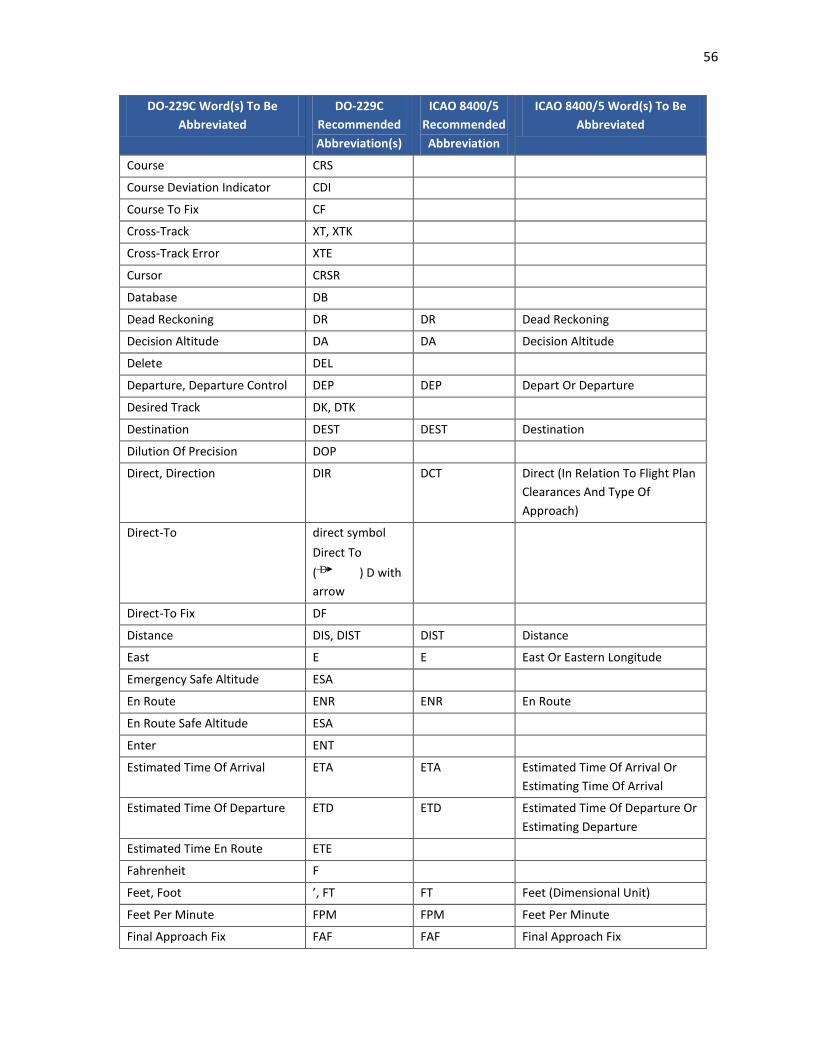
56
DO-229C Word(s) To Be Abbreviated
DO-229C Recommended Abbreviation(s)
ICAO 8400/5 Recommended Abbreviation
ICAO 8400/5 Word(s) To Be Abbreviated
Course CRS
Course Deviation Indicator CDI
Course To Fix CF
Cross-Track XT, XTK
Cross-Track Error XTE
Cursor CRSR
Database DB
Dead Reckoning DR DR Dead Reckoning
Decision Altitude DA DA Decision Altitude
Delete DEL
Departure, Departure Control DEP DEP Depart Or Departure
Desired Track DK, DTK
Destination DEST DEST Destination
Dilution Of Precision DOP
Direct, Direction DIR DCT Direct (In Relation To Flight Plan Clearances And Type Of Approach)
Direct-To direct symbol Direct To ( D ) D with arrow
Direct-To Fix DF
Distance DIS, DIST DIST Distance
East E E East Or Eastern Longitude
Emergency Safe Altitude ESA
En Route ENR ENR En Route
En Route Safe Altitude ESA
Enter ENT
Estimated Time Of Arrival ETA ETA Estimated Time Of Arrival Or Estimating Time Of Arrival
Estimated Time Of Departure ETD ETD Estimated Time Of Departure Or Estimating Departure
Estimated Time En Route ETE
Fahrenheit F
Feet, Foot ’, FT FT Feet (Dimensional Unit)
Feet Per Minute FPM FPM Feet Per Minute
Final Approach Fix FAF FAF Final Approach Fix

57
DO-229C Word(s) To Be Abbreviated
DO-229C Recommended Abbreviation(s)
ICAO 8400/5 Recommended Abbreviation
ICAO 8400/5 Word(s) To Be Abbreviated
Final Approach Waypoint, For Waypoint Identifiers
f, FA, FAWP FAP Final Approach Point
Flight Level FL FL Flight Level
Flight Plan FPL PLN Flight Plan Cancellation (Message Type Designator)
From FR FM From
Full-Scale Deflection FSD
Global Positioning System GPS GPS Global Positioning System
Greenwich Mean Time GMT
Ground Speed GS GS Ground Speed
Heading HDG HDG Heading
Height Above Threshold HAT
HGT Height Above
Hold, Holding, Holding Pattern HLD HLDG Holding
Horizontal Alert Limit HAL
Horizontal Protection Limit HPL
Horizontal Situation Indicator HSI
Horizontal Uncertainty Level HUL
Initial Approach Waypoint, For Waypoint Identifiers
i, IA, IAWP IAF Initial Approach Fix
Instrument Flight Rules IFR IFR Instrument Flight Rules
Intermediate Waypoint IWP
Intersection INT INT Intersection
Knots KT
Latitude LAT LAT Latitude
Left L, LFT
Left Runway L L Left (Runway Identification)
Localizer LOC LLZ Localizer
Localizer-Type Directional Aid LDA
Longitude LON LONG Longitude
Magnetic M, MAG MAG Magnetic
QRD Magnetic Bearing
Mean Sea Level MSL MSL Mean Sea Level
Message MSG MSG Message
Meters M M Meters (Preceded By Figures)
Military Operating Area MOA MOA Military Operating Area

58
DO-229C Word(s) To Be Abbreviated
DO-229C Recommended Abbreviation(s)
ICAO 8400/5 Recommended Abbreviation
ICAO 8400/5 Word(s) To Be Abbreviated
Millibars mB
Minimum Decision Altitude MDA MDA Minimum Descent Altitude
Minimum En Route Altitude MEA MEA Minimum
Minimum Safe Altitude MSA MSA Minimum Sector Altitude
Missed-Approach Holding Waypoint
h, MH, MAHWP
Missed-Approach Waypoint, For Waypoint Identifiers
m, MA, MAWP MAPT Missed Approach Point
Nautical Mile nm, NM NM Nautical Miles
Nearest NRST
Non-Directional Beacon NDB NDB Non-Directional Radio Beacon
Non-Precision Approach NPA
North N N North Or Northern Latitude
Off Route Obstacle Clearance Altitude
OROCA
Offset OFST
Omni-Bearing Selector OBS
Outer Marker OM OM Outer Marker
Parallel Track PTK
Precision Approach PA
Present Position PPOS, PP PPSN Present Position
Procedure PROC PROC Procedure
Procedure Turn PT PTN Procedure Turn
Radial R, RAD RDL Radial
Radial/Distance R/D
Radius To Fix RF
Range RNG RG Range (Lights)
Receiver Autonomous Integrity Monitoring
RAIM
Relative Bearing RB
Required Navigation Performance
RNP RNP Required Navigation Performance
Reverse, Revision, Revise REV
Right R, RT RITE Right Turn Of Direction
Right Runway R R Right (Runway Identification)
Route RTE RTE Route
Runway RWY RWY Runway

59
DO-229C Word(s) To Be Abbreviated
DO-229C Recommended Abbreviation(s)
ICAO 8400/5 Recommended Abbreviation
ICAO 8400/5 Word(s) To Be Abbreviated
Selective Availability SA
Sequence, Sequencing SEQ
Setup SET
South S S South Or Southern Latitude
Special Use Airspace SUA
Standard Terminal Arrival Route
STAR STAR Standard Instrument Arrival
Suspend SUSP
Temperature TEMP T Temperature
Test TST
Threshold Crossing Height TCH
Time To Alert TTA
To TO TO To... (Place)
To/From T/F
Tower TWR
Track TK, TRK TR Track
Track To Fix TF
Track Angle Error TKE
Transition Altitude TA TA Transition Altitude
Transition Level TL TRL Transition Level
True T
True Airspeed TAS TAS True Airspeed
QTE True Bearing
True Heading TH
Variation VAR
Vector VECT
Vector To Final VTF
Vertical Navigation VNAV, VNV
Vertical Protection Level VPL
Vertical Speed VS
Vertical Track VTK
Vertical Track Error VTE
Vertical Uncertainty Level VUL
VHF Omni-Directional Range VOR VOR VHF Omnidirectional Radio Range
Warning WARN, WRN WRNG Warning

60
DO-229C Word(s) To Be Abbreviated
DO-229C Recommended Abbreviation(s)
ICAO 8400/5 Recommended Abbreviation
ICAO 8400/5 Word(s) To Be Abbreviated
Waypoint WPT
West W W West Or Western Longitude
Wide Area Augmentation System
WAAS
World Geodetic System WGS
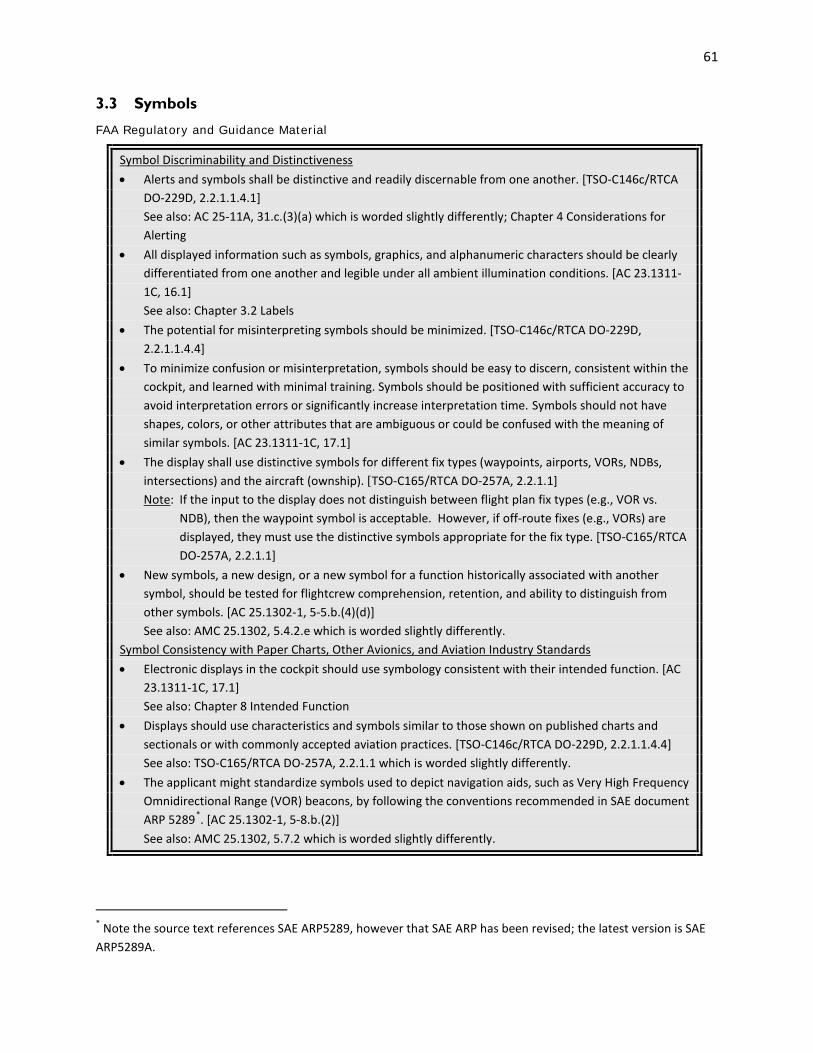
61
3.3 Symbols
FAA Regulatory and Guidance Material
Symbol Discriminability and Distinctiveness • Alerts and symbols shall be distinctive and readily discernable from one another. [TSO-C146c/RTCA
DO-229D, 2.2.1.1.4.1] See also: AC 25-11A, 31.c.(3)(a) which is worded slightly differently; Chapter 4 Considerations for
Alerting • All displayed information such as symbols, graphics, and alphanumeric characters should be clearly
differentiated from one another and legible under all ambient illumination conditions. [AC 23.1311-1C, 16.1] See also: Chapter 3.2 Labels
• The potential for misinterpreting symbols should be minimized. [TSO-C146c/RTCA DO-229D, 2.2.1.1.4.4]
• To minimize confusion or misinterpretation, symbols should be easy to discern, consistent within the cockpit, and learned with minimal training. Symbols should be positioned with sufficient accuracy to avoid interpretation errors or significantly increase interpretation time. Symbols should not have shapes, colors, or other attributes that are ambiguous or could be confused with the meaning of similar symbols. [AC 23.1311-1C, 17.1]
• The display shall use distinctive symbols for different fix types (waypoints, airports, VORs, NDBs, intersections) and the aircraft (ownship). [TSO-C165/RTCA DO-257A, 2.2.1.1]
Note: If the input to the display does not distinguish between flight plan fix types (e.g., VOR vs. NDB), then the waypoint symbol is acceptable. However, if off-route fixes (e.g., VORs) are displayed, they must use the distinctive symbols appropriate for the fix type. [TSO-C165/RTCA DO-257A, 2.2.1.1]
• New symbols, a new design, or a new symbol for a function historically associated with another symbol, should be tested for flightcrew comprehension, retention, and ability to distinguish from other symbols. [AC 25.1302-1, 5-5.b.(4)(d)]
See also: AMC 25.1302, 5.4.2.e which is worded slightly differently. Symbol Consistency with Paper Charts, Other Avionics, and Aviation Industry Standards • Electronic displays in the cockpit should use symbology consistent with their intended function. [AC
23.1311-1C, 17.1] See also: Chapter 8 Intended Function • Displays should use characteristics and symbols similar to those shown on published charts and
sectionals or with commonly accepted aviation practices. [TSO-C146c/RTCA DO-229D, 2.2.1.1.4.4] See also: TSO-C165/RTCA DO-257A, 2.2.1.1 which is worded slightly differently. • The applicant might standardize symbols used to depict navigation aids, such as Very High Frequency
Omnidirectional Range (VOR) beacons, by following the conventions recommended in SAE document ARP 5289*. [AC 25.1302-1, 5-8.b.(2)]
See also: AMC 25.1302, 5.7.2 which is worded slightly differently.
* Note the source text references SAE ARP5289, however that SAE ARP has been revised; the latest version is SAE ARP5289A.

62
Symbols Used for Only One Purpose • Within the flight deck, avoid using the same symbol for different purposes, unless it can be shown
that there is no potential for misinterpretation errors or increases in flightcrew training times. [AC 25-11A, 31.c.(3)(b)]
• The shape, dynamics, and other symbol characteristics representing the same function on more than one display on the same flight deck should be consistent. [AC 25-11A, 31.c.(3)(a); AC 23.1311-1C, 17.1]
• Symbols representing the same functions on more than one display should be the same. Different symbols among different displays for the same functions may be acceptable only if it can be clearly shown that the pilot can quickly and consistently recognize, interpret, and respond correctly without incurring excessive pilot workload. [AC 23.1311-1C, 17.1]
• Symbols used for one purpose on published charts should not be used for another purpose on the equipment display. [TSO-C146c/RTCA DO-229D, 2.2.1.1.4.4; TSO-C165/RTCA DO-257A, 2.2.1.1]
See also: Chandra, et al., 2003, 2.4.13 Symbol Orientation • All symbols shall be depicted in an upright orientation except for those designed to reflect a
particular compass orientation. [TSO-C165/RTCA DO-257A, 2.2.1.1] Note: This requirement does not apply to RAC data because it may not be able to meet this
requirement due to the fundamental nature of that data. It does apply to vector data superimposed onto a Raster Chart. [TSO-C165/RTCA DO-257A, 2.2.1.1]
• Symbols indicating a particular compass orientation shall maintain that compass orientation at all times. An example of this is a depiction of a runway symbol that maintains proper compass orientation as the map rotates. [TSO-C165/RTCA DO-257A, 2.2.1.1]
• If heading or track is available, the aircraft/ownship symbol shall be directional, oriented to either heading or track. [TSO-C165/RTCA DO-257A, 2.2.1.1]
• If the system supports more than one aircraft symbol directional orientation (e.g., heading and track), then the current aircraft symbol orientation shall be indicated. [TSO-C165/RTCA DO-257A, 2.2.1.1]
Directionality • If directional data is available, the ownship symbol should indicate directionality. [TSO-C165/RTCA
DO-257A, 2.3.1.2] • If direction/track is not available, the ownship symbol shall not imply directionality. [TSO-C165/RTCA
DO-257A, 2.3.1.2] • If ownship directionality information becomes unusable then this condition should be indicated on
the display. [TSO-C165/RTCA DO-257A, 2.3.1.2] Note: One method for indicating the loss of directionality information may consist of changing the
ownship depiction from a directional symbol to a non-directional symbol (e.g., circle). [TSO-C165/RTCA DO-257A, 2.3.1.2]
• If the ownship symbol is directional, the front of the symbol that conveys directionality (e.g., apex of a chevron or nose of the aircraft if using an aircraft icon) should correspond to the aircraft location. [TSO-C165/RTCA DO-257A, 2.3.1.2]
• If the ownship symbol is non-directional, the aircraft location should correspond to the center of the non-directional symbol. [TSO-C165/RTCA DO-257A, 2.3.1.2]

63
Overlaying Symbols • Applicants should give careful attention to symbol priority when displaying one symbol overlaying
another symbol by editing out the secondary symbol, to ensure higher priority symbols remain viewable. [AC 25.1302-1, 5-5.b.(4)(c)]
See also: AMC 25.1302, 5.4.2.e which is worded slightly differently. • The ownship symbol shall be unobstructed. [TSO-C165/RTCA DO-257A, 2.2.1.1] Note: Exceptions may be allowed for multi-function displays depicting higher priority information
that are required by regulation that may temporarily obstruct the ownship symbol (e.g., TCAS Traffic Advisory). [TSO-C165/RTCA DO-257A, 2.2.1.1]
Symbol Position Accuracy • Symbols that represent physical objects (for example, navigational aids and traffic) should not be
misleading as to the object’s physical characteristics (including position, size, envelope, and orientation). [AC 25-11A, 31.c.(3)(a); AC 23.1311-1C, 17.1]
• Symbols should be positioned with sufficient accuracy to avoid interpretation errors or significantly increase interpretation time. [AC 25-11A, 31.c.(3)(a)]
• Symbols which are interpreted relative to each other, (e.g., cursors on scales, command bars against reference points, etc.), including mechanically produced symbols that are interpreted relative to electronically produced symbols, shall be aligned, including parallax effects throughout the design eye position viewing envelope, to preclude misinterpretation of information. [TSO-C113a/SAE AS8034B, 4.2.2]
• The display absolute positional accuracy shall be better than 5% of the maximum diagonal dimension of the display. In no case shall the absolute positional error cause erroneous data to be presented. [TSO-C113a/SAE AS8034B, 4.2.3]
• All displayed symbols and graphics shall be positioned (i.e., drawn or rendered) accurately relative to one another such that placement errors are less than .013 inches on the map depiction or 1% of the shortest axis (i.e., horizontal and vertical dimension) of the map depiction, and orientation errors are less than 3° with respect to the values provided by the position and database sources. [TSO C165/RTCA DO-257A, 2.2.1; TSO-C113a/SAE AS8034B, 4.2.2]
Notes: [TSO C165/RTCA DO-257A, 2.2.1] 1. Refer to RTCA DO-257A, Appendix G for display resolution issues. 2. See additional notes in RTCA DO-257A. [TSO C165/RTCA DO-257A, 2.2.1] • The display of obstructions shall reflect database precision. [TSO-C146c/RTCA DO-229D, 2.2.1.1.4.6] • It is important that the inherent inaccuracies of displays be made apparent to the user. The
recommended method for accomplishing this is to depict a “circle of uncertainty” around the aircraft symbol. [TSO-C165/RTCA DO-257A, Appendix F, F.3]
• The radius of the circle should consider feature placement standards of the originating charting agency and errors introduced by the processing steps. It is recommended that the radius indicate a 2-sigma (95%) confidence level based on a numerical analysis of the inherent errors. [TSO-C165/RTCA DO-257A, Appendix F, F.3]
• If a position source other than Global Navigation Satellite System (GNSS) is used, the position error inherent in the position sensor system must be taken into account and a corresponding increase of the radius of the circle of uncertainty may be required. [TSO-C165/RTCA DO-257A, Appendix F, F.3]

64
• In addition to the above technique, it is recommended that manufacturers include text similar to the following in the user manual and/or on a product identification screen. [TSO-C165/RTCA DO-257A, Appendix F, F.3]
Note: Discrepancies [of up to Xnm] in the placement of airport and navigational aid symbols are known to exist in the source material. This product is not intended for navigation guidance. [TSO-C165/RTCA DO-257A, Appendix F, F.3]
• The applicant should determine the symbol placement and accuracy standards of the supplier and apply these to the calculation of the “radius of uncertainty”. [TSO-C165/RTCA DO-257A, Appendix F, F.3.1]
Symbol Quality • Lines, symbols, and characteristics shall not have distracting gaps, geometric distortions (such as
tails, squiggles, skews) or motion anomalies discernible from the design eye position viewing envelope which cause erroneous interpretation. Any distorted dimension should not exceed one half the local line width in the area of the distortion. [TSO-C113a/SAE AS8034B, 4.2.8]
• Image distortion should not compromise image interpretation. Images meant to provide information about depth (for example, 3-Dimensional type perspective displays) should provide adequate depth information to meet the intended function. [TSO-C113a/SAE AS8034B, 4.2.8]
See also: Chapter 8 Intended Function • Display symbology that is in motion (translation and/or rotation) should not have distracting jitter,
jerkiness, or ratcheting effects. Dynamic symbols should maintain luminance, contrast, color, line width, and symbol quality characteristics independent of their rate of motion. Pointers and bar graphs should be designed with built in hysteresis or smoothing of the displayed value such that when a constant or near constant value of a parameter is to be displayed, objectionable motion is eliminated. [TSO-C113a/SAE AS8034B, 4.2.8.2]
See also: Chapter 3.5 Graphical Depictions and Images
Other Recommendation(s)
Symbol Discriminability and Distinctiveness • Symbols should be used for a single purpose within the system. [RTCA DO-256, 2.1.3.1] • Symbols shall be discriminable at a nominal viewing distance of 29”, a minimum viewing distance of
10”, and a maximum viewing distance of 40” under all flight deck lighting conditions. (SAE AIR 1093*). [RTCA DO-256, 2.1.3.1]
• Symbols should be distinguishable based on their shape alone, without relying upon secondary cues such as color and text labels. [Chandra, et al., 2003, 2.4.13]
• Symbols should be designed so that they are discriminable when presented on the minimum expected display resolution when viewed from the maximal intended viewing distance. [Chandra, et al., 2003, 2.4.13]
Note: SAE ARP4102/7 on Electronic Display Symbology for EADI/PFD gives minimum symbol visual angles as 6 milliradians for primary data, and 4 milliradians for secondary and descriptive data. [Chandra, et al., 2003, 2.4.13]
• A change in a small symbol feature, that may be easily missed, should not imply a significant difference in the operational interpretation of the symbol. (Yeh and Chandra, 2005)
* Note the source text references SAE AIR 1093, however that SAE AIR has been revised; the latest version is SAE AIR1093A.

65
• If symbols are modified to convey different levels of information, the modifications should be based on an explicit set of rules that are clearly stated. Any modification to the symbol shape should not interfere with recognition or discrimination of the basic symbol. (Yeh and Chandra, 2005)
• The feature modified should be salient and clearly distinguishable. (Yeh and Chandra, 2005) Symbol Size • The minimum character height should be 0.15 in (3.8 mm) for fixed symbols and 0.20 in (5.1 mm) for
moving symbols. (McAnulty, 1995)
Background
The design and selection of symbols should consider the ways in which the symbols are used. Inconsistency in symbol design increases the potential for confusion and misinterpretation. A symbol is distinctive if it is easy to discriminate from other symbols. Sometimes manufacturers may choose to enhance the design of a symbol by adding details to create their own look and feel; in these cases, it will be important to ensure that the enhancements do not impact the symbol’s recognizability. A Volpe Center technical report, Designing and Evaluating Symbols for Electronic Displays of Navigation Information: Symbol Stereotypes and Symbol-Feature Rules (DOT/FAA/AR-05/48; DOT-VNTSC-FAA-05-16), provides considerations for testing new symbols for recognition.
A symbol’s appearance will vary depending on the physical qualities of the display. The display resolution, contrast, brightness, color, and rendering techniques, such as anti-aliasing (i.e., smoothing techniques to reduce the perception of jagged edges), influence the legibility of the information and the level of detail that can be depicted. Some symbols may have fine details that are difficult to see under degraded display conditions or when viewed off-angle. In particular, some symbols on paper charts that are drawn with high level of detail and may not transfer well to electronic displays, if they are small. To ensure that the key features of a symbol are preserved when shown on an electronic display, manufacturers may need to specify a minimum size.
Example(s)
The symbols below illustrate the problems of using the same symbol shape for different meanings.
US fly-by waypoint Previous ICAO fly-over
waypoint Current ICAO fly-over waypoint
The US symbol for a fly-by waypoint is identical to the International Civil Aviation Organization (ICAO) recommended symbol for a fly-over waypoint, but the operational meanings for these two symbols are significantly different. If these symbols were misinterpreted, the resulting flight path deviation could have safety implications. In 2000, this discrepancy and potential safety risk was resolved when ICAO added a circle to their recommended fly-over waypoint symbol (see “current ICAO fly-over waypoint”) (Yeh and Chandra, 2005).
The figures below shows how key features or details, when applied inconsistently, can cause symbols to be misinterpreted.
TACAN symbol surrounded by
a circle border (fly-over) TACAN symbol surrounded by
a compass rose

66
The TACAN symbol with a circle border on the left is a fly-over reporting point. The TACAN symbol on the right also has a circular border, but in this case, the circle border represents a compass rose. Because the circle border is so compelling, pilots may misinterpret symbols surrounded by a compass rose as fly-over waypoints (see Yeh and Chandra, 2005, for more information). This is an example where the same key feature (the circle) has two different meanings.
In the example below we see a case where a key feature (symbol fill) is not applied clearly. The fill of a symbol is often used to distinguish a navigation aid as being compulsory (filled) or on-request (unfilled). The example below is intended to show that symbol fill must be applied in a salient way to prevent misinterpretation.
US fly-by waypoint Prototype symbol
When presented with these symbols, pilots were not able to determine at a glance if the US fly-by waypoint symbol on the left was filled or not, particularly when compared to those symbols that are completely filled (e.g., the symbol on the right) (see Yeh and Chandra, 2005, for more information). Consequently, pilots were not able to accurately identify whether the symbol on the left was compulsory or on-request.
To avoid some of the problems listed in these examples which result from creating new symbols, it is recommended that manufacturers first consider using an existing symbol set or at least considering the existing and currently approved symbol sets. Symbols currently in use by various avionics and chart manufacturers for navigation aids and airports as well as line and linear patterns have been compiled. They are documented in a Volpe Center report, Survey of Symbology for Aeronautical Charts and Electronic Displays: Navigation Aids, Airports, Lines, and Linear Patterns (DOT/FAA/AR-07/66; DOT-VNTSC-FAA-08-01). Additionally, the following SAE International documents contain recommended symbols: 1. SAE ARP4102/7, Electronic Displays, Appendices A through C (for primary flight, navigation, and
powerplant displays); 2. SAE ARP5289A, Electronic Aeronautical Symbols, (for depiction of navigation symbology); and 3. SAE ARP5288, Transport Category Airplane Head Up Display (HUD) Systems, (for HUD symbology).

67
3.4 Markings, Dials, Tapes, and Numeric Readouts
FAA Regulatory and Guidance Material
Markings • For each instrument, when markings are on the cover glass of the instrument, there must be means
to maintain the correct alignment of the glass cover with the face of the dial. [14 CFR 25.1543(a)] See also: 14 CFR 23.1543(a), 27.1543(a), and 29.1543(a) which are worded slightly differently. • Color code markings are frequently incorporated on the moving face of a tape or digital
presentation. In such cases, it is mandatory that limit markings be affixed adjacent to the presentation, or that another means be provided so that the pilot can anticipate approaching a limit. The beginning and end of normal and cautionary ranges should be marked adjacent to the display. The entire range need not be color coded adjacent to the display if the colors are integral on the face of the tape or in the individual digital segments. Marking of limit values solely on the tape or in the colored light segments alone is unsatisfactory. [AC 27-1B, AC 27.1541/AC 27.1543b(7)(ii); AC 29-2C, AC 29.1541/AC 29.1543b(7)(ii)]
• Digital readouts or present value indices incorporated into qualitative displays should not make the scale markings or graduations unusable as they pass the present value index. [AC 25.1302-1, 5-5.b.(1)(c); AMC 25.1302, 5.4.2.a]
• Scale markings should be clear throughout all values presented in the readout. [AC 25.1302-1, 5-5.b.(1)(c)]
• All indicating means displayed (indicia, pointers, symbols, etc.) shall be completely visible from any eye position within the viewing envelope(s) as specified by the equipment manufacturer. Text and symbology shall be readily discernible and should be legible and readable within the specified viewing envelope(s). [TSO-C113a/SAE AS8034B, 4.2.1]
• Markings shall be provided at intervals not exceeding 20 feet of altitude with major markings at 100 foot intervals. [TSO-C10b/SAE AS392C, 4.2.1]
• Delimiters, such as tick marks, should allow rapid interpretation without adding unnecessary clutter. Markings and labels should be positioned such that their meaning is clear yet they do not hinder interpretation. Pointers and indexes should not obscure the scales or delimiters such that they can no longer be interpreted. Pointers and indexes should be positioned with sufficient accuracy for their intended function. Accuracy includes effects due to data resolution, latency, graphical positioning, etc. [AC 25-11A, 31.c.(4)(b).3]
See also: Chapter 3.2 Labels; Chapter 8 Intended Function • Airspeed scale markings such as stall warning, maximum operation speed/maximum operating mach
number, or flap limits, should be displayed to provide the flightcrew a quick-glance sense of speed relative to key targets or limits. The markings should be predominant enough to confer the quick-glance sense information, but not so predominant as to be distracting when operating normally near those speeds (for example, stabilized approach operating between stall warning and flap limit speeds). [AC 25-11A, Appendix 1, 2.1]
• The density of information on the display should be compatible with the pilot's ability to recognize essential information and to minimize misinterpretation. Symbols and markings that are displayed during specific phases of flight may be removed at other times to reduce clutter. Establish an information prioritization scheme to ensure the clear presentation of essential information. [AC 23.1311-1C, 17.3]
See also: Chapter 3.8 Integrated Display Issues

68
• The applicable flightcrew members, seated at their stations and using normal head movement, must be able to see and read display format features such as fonts, symbols, icons and markings so they can safely perform their tasks. In some cases, cross-flight-deck readability may be required to meet the intended function (§ 25.1301(a)) that both pilots must be able to access and read the display. [AC 25.1302-1, 5-5.b.(2)] See also: Chapter 2.3 Field-of-View and Chapter 8 Intended Function
Dials and Tapes • Linear tape altimeter displays should include enhancements denoting standard 500- and 1,000-foot
increments. These displays should convey unambiguously, at a glance, the present altitude. Combining altimeter scale length and markings, therefore, should be enough to allow sufficient resolution for precise manual altitude tracking in level flight. They should also have enough scale length and markings to reinforce the pilot’s sense of altitude. The scale length should also allow sufficient look-ahead room to adequately predict and accomplish level off. [AC 23.1311-1C, 17.8.a]
• The vertical velocity shall be indicated by means of a pointer, dial tape, drum, or other type of moving element, or by a digital display with appropriate direction indication. Relative motion of the index with respect to the scale, or of the direction indicator (either the index or the scale may be the moving element) must be clockwise, up, or to the right for ascending vertical velocity. [TSO-C8e/SAE AS8016A, 3.1]
• All indicating means displayed (indicia, pointers, symbols, etc.) shall be completely visible from any eye position within the viewing envelope(s) as specified by the equipment manufacturer. Text and symbology shall be readily discernible and should be legible and readable within the specified viewing envelope(s). [TSO-C113a/SAE AS8034B, 4.2.1]
Note: It is the responsibility of the equipment installer to determine that the required aircraft viewing envelope is within the specified display viewing envelope(s). [TSO-C113a/SAE AS8034B, 4.2.1]
• The indicating means shall be limited in such a way that the moving element will not move more than (a) 10 degrees for circular display, or (b) 0.25 inch (.6 mm) for linear displays beyond the greatest graduation in both ascending and descending directions. When the instrument is pegged at its maximum rate indication, the direction of that indication, whether ascending or descending, shall be clear and unambiguous. If a digital display is used, a positive indication shall be provided on the display when the vertical velocity of the aircraft exceeds the instrument readout capability. [TSO-C8e/SAE AS8016A, 3.2.3]
• One of the following methods of indication shall be employed: [TSO-C6e/SAE AS8013A, 3.8] Method I Rotating dial display with fixed lubber line. The dial shall rotate counterclockwise for right
turns. Method II Horizontal scale display with fixed lubber line. The graduations shall move to the left for
right turns. Method III Rotating pointer with fixed graduated dial. Pointer shall rotate clockwise for right turns.
Dial position may be settable. • The designation "RPM", plus such other nomenclature as may be necessary, shall be legibly marked
on the dial and may be of the same finish as the numerals. [TSO-C49b/SAE AS404C, 4.1.3.4] • The displayed range should be sufficient to perform the intended function. If the entire operational
range is not shown at any given time, the transition to the other portions of the range should not be distracting or confusing. [AC 25-11A, 31.c.(4)(b).1]
See also: Chapter 8 Intended Function

69
• When the glideslope pointer is being driven by a RNAV (area navigation) system with VNAV (vertical navigation) or ILS (instrument landing system) look-alike functionality, the pointer should not be marked “GS” or “glideslope.” [AC 25-11A, 36.b.(5)(b)]
• The display of a round dial, moving pointer with a digital read-out is acceptable. To accommodate a larger operating range on a linear tape, adopt a moving scale display with the present value on a digital readout. Since the moving scale display typically does not provide any inherent visual cue of the relationship of present value to low or high airspeed limits, quick-glance awareness cues may be needed. [AC 23.1311-1C, 17.6]
• The minimum visible airspeed scale length found acceptable for moving scales has been 80 knots; since this minimum is dependent on other scale attributes and airplane operational speed range, variations from this should be verified for acceptability. [AC 25-11A, Appendix 1, 2.1]
Intervals/Increments • Airspeed scale graduations in 5-knot increments with graduations labeled at 20-knot intervals are
acceptable. In addition, a means to rapidly identify a change in airspeed (for example, speed trend vector or acceleration cue) should be provided on moving scale tapes; if trend or acceleration cues are used, or a numeric present value readout is incorporated in the airspeed display, scale markings at 10-knot intervals are acceptable. [AC 25-11A, Appendix 1, 2.1]
• Minimum altimeter graduations should be in 100-foot increments with a present value readout, or 50-foot increments with a present value index only. Due to operational requirements, it is expected that airplanes without either 20-foot scale graduations or a readout of present value, will not be eligible for Category II low visibility operation with barometrically determined decision heights. [AC 25-11A, Appendix 1, 2.1]
• The following method of indication shall be employed. For indicating an ascent in altitude, the sensitive pointer shall move in a clockwise direction completing one revolution (360°) for each 1,000 feet of altitude change. A means shall be provided for showing the multiples of 1,000 feet. [TSO-C10b/SAE AS392C, 4.1]
• Graduation (If Applicable): The graduations shall be arranged to provide the maximum readability consistent with the accuracy of the instrument, with at least 100 ft/minute (30 m/minute), graduations to 1000 ft/minute (300 m/minute). Major graduations shall be at 1000 ft/minute (300 m/minute), intervals and the minor graduations shall be at 500 ft/minute (150 m/minute) intervals. [TSO-C8e/SAE AS8016A, 3.2.1]
• All graduations shall be multiples of 10 RPM. The increment between graduations shall not exceed 2-1/2% of full scale, above 600 RPM. [TSO-C49b/SAE AS404B, 4.1.3.2]
• The indicators shall be provided with degree graduations at intervals not to exceed 5 degrees, with major graduations every 10 degrees and with numerals at intervals not greater than 30 degrees, except that the 0, 90, 180, and 270 degrees positions may be marked N, E, S, and W, respectively. [TSO-C6e/SAE AS8013A, 3.10.1]
• Sufficient numerals shall be marked to identify positively and quickly all graduations. [TSO-C49b/SAE AS404C, 4.1.3.3; TSO-C44c/SAE AS407D, 4.2.2]
See also: TSO-C47a/SAE AS408C, 4.1.3 and TSO-C8e/SAE AS8016A, 3.2.2 which are worded slightly differently.
• Numerals shall distinctly indicate the graduations to which each applies. [TSO-C44c/SAE AS407D, 4.2.2; TSO-C47a/SAE AS408C, 4.1.3]
• Major graduations shall be used at intervals not to exceed 10% of full scale value. [TSO-C44c/SAE AS407D, 4.2.3]

70
• When counters are incorporated in the instrument, they shall indicate increments no larger than 10 pounds or 2 gallons. [TSO-C44c/SAE AS407D, 4.2.4]
Numeric Readouts • When numeric readouts are used in conjunction with scales, they should be located close enough to
the scale to ensure proper association, yet not detract from the interpretation of the graphic or the readout. [AC 25-11A, 31.c.(4)(b).2]
• For North, numeric readouts of heading should indicate 360, as opposed to 000. [AC 25-11A, 31.c.(4)(a).3]
• Digital reading alphanumeric displays are most valuable when integrated with an analog display by adding a precise, quantitative indication to complement an analog display's qualitative indication. Proper integration should include a means for pilots to clearly associate the analog and digital indications (e.g., via close proximity). Digital reading alphanumeric powerplant display formats should not be used in place of analog formats to indicate values of engine parameters where trend or rate-of-change information is important for safety, or when the pilot needs to monitor parameters with a quick glance. [AC 23.1311-1C, 9.4]
• Digital read-out presentation of airspeed and altitude should convey to the pilot a quick-glance sense of rate and trend information. For airspeed and altitude, digital read-out alphanumeric displays may not be adequate on the primary display or on the standby instruments, but it is acceptable on a display used as supplementary information. If the applicant proposes a digital read-out alphanumeric display, they should show that the pilot response is equal to or better than the response with analog data (symbology) using a human factors evaluation. [AC 23.1311-1C, 17.5]
Accuracy • Scale resolution should be sufficient to perform the intended task. Scales may be used without an
associated numeric readout if alone they provide sufficient accuracy for the intended function. [AC 25-11A, 31.c.(4)(b).2]
• The graduations shall be arranged to provide the maximum of readability consistent with the accuracy of the instrument. [TSO-C47a/SAE AS408C, 4.1.2]
See also: Chapter 8 Intended Function • Data accuracy of the numeric readout should be sufficient for the intended function and to avoid
inappropriate flightcrew response. The number of significant digits should be appropriate to the data accuracy. Leading zeroes should not be displayed unless convention dictates otherwise (for example, heading and track). As the digits change or scroll, there should not be any confusing motion effects such that the apparent motion does not match the actual trend. [AC 25-11A, 31.c.(4)(a).1]
See also: Chapter 8 Intended Function
Other Recommendation(s)
Dials and Tapes • Scale axes should be labeled. (McAnulty, 1995) • Scale intervals should be graduated in values of 1, 2, or 5 (with 1 being the most preferred, and 2 the
least preferred), or decimal multiples of those values. (McAnulty, 1995; MIL-STD-1472G) • Scales that are numbered in intervals of 1, 10, 100, etc, and subdivided into 10 graduation intervals
are preferred. (McAnulty, 1995) • For circular scales, numbers should increase in a clockwise direction. (MIL-STD-1472G, 5.2.2.5.3.c)

71
• For fixed pointer linear scales, numbers should increase as the pointer is moved from left to right or bottom to top. (MIL-STD-1472G, 5.1.2.3.6)
• The pointer should be designed so it is clear which end is the pointing end and which end is the tail. • Pointers should be located at the bottom of horizontal scales and to the right of vertical scales. (MIL-
STD-1472G) • The pointer should not obscure digital scale values. (McAnulty, 1995) Numeric Readouts • The information format should be directly usable and should not require any mental conversion
(e.g., transposition, calculation, or interpolation into other units). (McAnulty, 1995)
Background
The display format can affect how salient and useful the information will be. Scales, dials, and tapes are analog display formats that show dynamic information symbolically whereas a numeric readout is a digital format. The precision of the information presented should meet the needs of the pilot for flight management rather than be determined by the capabilities of the software. Numeric counters offer greater accuracy than analog displays and may be appropriate when precise values are needed. However, analog displays are easier to interpret at a glance than numeric counters, and are more appropriate for presenting qualitative information, such as changes in values and trends in the rate and pattern of the change. Scale indicators are particularly useful for showing trend or direction-of-motion information. If the display format used is not appropriate to the task being performed, the time required to complete the task and the risk of errors will increase. Additionally, display formats that are not familiar or that are not labeled properly in terms of orientation, range, or scale may be no more effective than text alone (Mejdal, McCauley, and Beringer, 2001). Another unintended consequence is that head-down time will increase as the pilot spends more time looking at the display to obtain the necessary information (McAnulty, 1995; Uhlarik, Raddatz, and Elgin, in preparation; Wickens, Gordon, and Liu, 1998).
In designing an analog display, several attributes of the pointer and the scale (numbering and marking) can be varied. The pointer can vary in location, size, shape, and color, and the scale numbers and markers can vary in their orientation, position, spacing, and intervals shown. The selection of these attributes affects the usability of the analog display. For example, some pointers may be designed to resemble the object it refers to, but highly detailed pointers may create false or misleading cues, and it may not be clear which end of the figure is the pointing end.
Scales can be designed so that the pointer is fixed and the scale moves or so that the scale is fixed and the pointer moves. Moving pointer, fixed-scales are generally preferred to fixed pointer, moving scales because a moving pointer inherently provides a cue as to whether the present value is high or low with respect to system limits. However, when a large operating range must be presented, a moving scale may be needed but quick-glance awareness cues may be supported (Wickens and Hollands, 2000).
Example(s)
Scales, dials, tapes, and numeric readouts can be used concurrently to present information in a complementary manner. A vertical tape altitude indicator that provides a numeric readout next to the moving pointer supports both quick estimation of altitude (e.g., through the position of the moving pointer) and accuracy (the numeric readout). In the depiction of heading information using a compass rose, the rotation of the compass rose provides a global cue regarding heading change, whereas a numeric readout indicates the precise heading (McAnulty, 1995; Uhlarik, Raddatz, and Elgin, in preparation; Wickens, Gordon, and Liu, 1998).

72
Analog dials may be arranged so that all pointers are aligned in the same direction when a common, stable operating environment exists. This creates an emergent feature, that is an overall feature that is formed by the group of dials, and provides a shortcut to determining the value of each dial. Such a design can facilitate error detection, since any deviations will disrupt the pattern.

73
3.5 Graphical Depictions and Images
FAA Regulatory and Guidance Material
General • Graphics and display indications should: [AC 25-11A, 31.c.(4)] - Be readily understood and compatible with other graphics and indications in the flight deck. - Be identifiable and readily distinguishable. • To avoid visual clutter, graphic elements should be included only if they add useful information
content, reduce flightcrew access or interpretation time, or decrease the probability of interpretation error. [AC 25-11A, 31.c.(4)(c).1]
• Images should be of sufficient size and include sufficient detail to meet the intended function. The pilots should be able to readily distinguish the features depicted. [AC 25-11A, 31.g.(1)]
See also: Chapter 8 Intended Function • All images, but especially dynamic images, should be located or controllable so they do not distract
the pilots from required tasks. [AC 25-11A, 31.g.(1)] • The source and intended function of the image and the level of operational approval for using the
image should be provided to the pilots. This can be accomplished using the airplane flight manual, image location, adequate labeling, distinct texturing, or other means. [AC 25-11A, 31.g.(1)]
See also: Chapter 8 Intended Function • Undesired afterimages that persist on the display should not be readily discernible day or night,
should not be distracting, and shall not cause an erroneous interpretation of the display. [TSO-C113a/SAE AS8034B, 4.2.10]
• It should be easy to cross-check map formats with paper renditions of the same information, such as instrument approach procedure charts and sectionals. [TSO-C146c/RTCA DO-229D, 2.2.1.1.4.6]
Orientation • To the extent it is practical and necessary, the graphic orientation and the flightcrew’s frame of
reference should be correlated. [AC 25-11A, 31.c.(4)(c).2] • If there are multiple depictions, such as “thumbnail” or overlaid depictions, the orientation (for
example, heading up, track up, North up, etc.) should be the same for each depiction. This does not apply to other systems where the captain and first officer may select different presentations of the same information and are used exclusively by that flightcrew member. [AC 25-11A, 31.c.(4)(c).3]
• If there are multiple depictions, such as inset, inlays, or overlayed depictions, the orientation (for example, heading up, track up, North up, etc.) should be the same for each depiction. This does not apply to other systems where the pilot and copilot may select different presentations of the same information and are used exclusively by that pilot. [AC 23.1311-1C, 17.12.b]
See also: TSO-C165/RTCA DO-257A, 2.2.1.3 and SAE ARP5898, 8.3.5 which are worded slightly differently; Chapter 3.8 Integrated Display Issues
• Images should be oriented in such a way that their presentation is easily interpreted. [AC 25-11A, 31.g.(1)]
• The display shall have the capability to present map information in at least one of the following orientations: actual track-up or heading-up. [TSO-C165/RTCA DO-257A, 2.2.4]
Notes: [TSO-C165/RTCA DO-257A, 2.2.4] 1. In addition to the above, desired track-up and North-up orientations (to facilitate cross
checking with the paper charts and flight planning) are also acceptable. 2. Default of track-up or heading-up in-flight is encouraged.

74
3. This requirement does not apply to systems while displaying RAC data. See also: TSO-C146c/RTCA DO-229D, 2.2.1.1.4.6 which is worded slightly differently.
• If desired track-up orientation is used, the aircraft symbol shall be oriented to actual track or heading. [TSO-C165/RTCA DO-257A, 2.2.4]
• Current map orientation shall be clearly, continuously, and unambiguously indicated (e.g., track-up vs. North-up). [TSO-C165/RTCA DO-257A, 2.2.4]
Notes: [TSO-C165/RTCA DO-257A, 2.2.4] 1. Issue: systems exist that have four orientation modes available without any explicit
indication of mode: actual track-up, North-up, heading-up, desired track-up. The orientation mode selected must be continuously indicated. Alternatively, the indication could be done using external annunciators or an external switch that indicates the orientation currently selected.
2. An acceptable means of compliance would be to have a “desired track-up” (or DTK↑), “North-up” (or N ↑), “heading-up” (or HDG ↑) or “actual track-up” (or TRK ↑) on the display.
3. A compass arc/rose or North indicator is an acceptable means of compliance for a system that provides only two options (North-up and one other option).
• If the flight crew has selected a display orientation (e.g., track-up), that display orientation should be maintained until an action that requires an orientation change occurs. [TSO-C165/RTCA DO-257A, 2.2.4]
Note: Actions can include crew selection of a different orientation or a mode change (e.g., TCAS auto popup). [TSO-C165/RTCA DO-257A, 2.2.4]
• In desired track-up orientation, it is recommended that a track extension line that projects the actual track out from the aircraft be displayed. [TSO-C165/RTCA DO-257A, 2.2.4]
Moving Map Scale, Range, and Panning • Objects that change sizes (for example, as the map range changes) should not cause confusion as to
their meaning and should remain consistent throughout their size range. At all sizes the objects should meet the guidance of this chapter as applicable (that is, the objects should be discernable, legible, identifiable, placed accurately, not distracting, etc.). [AC 25-11A, 31.d.(4)]
• Map scale shall be appropriate and clear. [TSO-C146c/RTCA DO-229D, 2.2.1.1.4.6] See also: McAnulty, 1995
• Conflicting range scaling should not occur. Provide map range. [AC 23.1311-1C, 17.13] • The display shall have the capability of manually changing the map range. [TSO-C165/RTCA DO-257A,
2.2.4] • Current map range shall be indicated continuously. [TSO-C165/RTCA DO-257A, 2.2.4] • If the display is controlling the map range automatically, the mode (e.g., auto map range) should be
indicated. [TSO-C165/RTCA DO-257A, 2.2.4] • If the display is controlling the map range automatically, then the capability shall exist to activate or
deactivate the automatic map range. [TSO-C165/RTCA DO-257A, 2.2.4] Note: An acceptable method of compliance is to have a discrete control action (e.g., button push) to
activate the automatic range function. [TSO-C165/RTCA DO-257A, 2.2.4] • If the automatic map range function is deactivated, the display should maintain the last range scale
prior to deactivation until the flight crew manually selects another map range. [TSO-C165/RTCA DO-257A, 2.2.4]

75
• When the display is switched to a previously viewed page then the display should maintain the settings (e.g., range, pan) associated with that previously viewed page. [TSO-C165/RTCA DO-257A, 2.2.4]
• If a panning and/or range selection function is available, the equipment should provide the capability to return to an ownship-oriented display with a maximum of two discrete control actions (e.g., two button pushes). [TSO-C165/RTCA DO-257A, 2.2.4]
• When using the panning and/or range selection function, an indicator of ownship current position within the overall displayed image should be provided. [TSO-C165/RTCA DO-257A, 2.2.4]
• Symbol attributes that use scaling and dynamics should be appropriate for the performance level of the airplane. Conflicting range scaling should not occur. [AC 23.1311-1C, 17.13]
• The display should provide an indication if the map range is smaller (i.e., “zoomed in” closer) than the level supported by the accuracy and resolution of the data. [TSO-C165/RTCA DO-257A, 2.2.1] See also: Chapter 3.6 Map Database and Accuracy
• Users should be warned whenever they are viewing an image at a scale greater than its compiled scale. In addition, it is recommended that no system permit “zooming in” beyond a point where the viewed scale has been increased greater than twice its compiled scale. [TSO-C165/RTCA DO-257A, Appendix F, F.6]
• If the system allows for geographic point queries of the raster data (i.e., operator moves a cursor on the screen and can receive a geographic position output) the system should output geographic coordinates in intervals based on the resolution of the source raster image. [TSO-C165/RTCA DO-257A, Appendix F, F.6]
Image Stability See also information on display flicker in Chapter 2.1 Visual Display Characteristics • Graphic objects that translate or rotate should do so smoothly without distracting or objectionable
jitter, jerkiness, or ratcheting effects. Data update rates for information elements used in direct airplane or powerplant manual control tasks (such as attitude, engine parameters, etc.) equal to or greater than 15 Hertz have been found to be acceptable. [AC 25-11A, 31.d.(1)]
• Movement of display information elements should not blur, shimmer, or produce unintended dynamic effects such that the image becomes distracting or difficult to interpret. Filtering or coasting of data intended to smooth the motion of display elements should not introduce significant positioning errors or create system lag that makes it difficult to perform the intended task. [AC 25-11A, 31.d.(2)]
• When a symbol reaches the limit of its allowed range of motion, the symbol should either slide from view, change visual characteristics, or be self-evident that further deflection is impossible. [AC 25-11A, 31.d.(3)]
• Dynamic information should not appreciably change shape or color as it moves. [AC 25-11A, 31.d.(4)] • Movement of map information should be smooth throughout the range of aircraft maneuvers. [TSO-
C165/RTCA DO-257A, 2.2.4] Update Rate See also: Chapter 2.1 Visual Display Characteristics for information on refresh rates • The display update rate should be sufficient to preclude objectionable motion artifacts that could be
misleading or distracting. [AC 25-11A, 16.a.(9)] See also: AC 23.1311-1C, 19.0a which is worded slightly differently.

76
• The latency period induced by the display system, particularly for alerts, should not be excessive and should take into account the criticality of the alert and the required crew response time to minimize propagation of the failure condition. [AC 25-11A, 21.e.(8)]
• SAE ARPs provide recommended lag times for display of the format and primary flight data, and minimum rates for data updates, to meet symbol motion. A 50-60 Hz refresh rate is typically enough to remove traces of visible flicker on the display. Frequencies above 55 Hz for stroke symbology or non-interlaced raster and 30/60 Hz for interlace raster are generally satisfactory. Some map information may be judged as adequate for enroute navigation displays with update rates of at least 1 Hz, depending on the specific aircraft. Update other critical data, such as attitude, heading, or air data symbology, at a rate of at least 15 Hz, depending on the airplane. [AC 23.1311-1C, 19.0, b.]
• Display symbology that is in motion (translation and/or rotation) should not have distracting jitter, jerkiness, or ratcheting effects. Dynamic symbols should maintain luminance, contrast, color, line width, and symbol quality characteristics independent of their rate of motion. Pointers and bar graphs should be designed with built in hysteresis or smoothing of the displayed value such that when a constant or near constant value of a parameter is to be displayed, objectionable motion is eliminated. [TSO-C113a/SAE AS8034B, 4.2.8.2]
• Display data shall be updated at sufficient frequency to meet symbol motion requirements. In particular for pitch and roll the update rate should be a minimum of 15 Hz. [TSO-C113a/SAE AS8034B, 4.6.3]
• The display of information essential to the safety of flight should be thoroughly responsive and accurate to the operational requirements. Electronic display system delay effects of essential information, including attitude, airspeed, altitude, heading, and specific propulsion parameters, should not degrade the pilot's ability to control the airplane. Any lag introduced by the display system should be consistent with the airplane control task associated with that parameter. [AC 23.1311-1C, 19.0a.]
• The display update rate should be sufficient to preclude objectionable motion artifacts that could be misleading or distracting. [AC 25-11A, 16.a.(9)] See also: AC 23.1311-1C, 19.0a which is worded slightly differently.
• Any lag introduced by the display system should be consistent with the airplane control task associated with that parameter. In particular, display system lag (including the sensor) for attitude which does not exceed a first order equivalent time constant of 100 milliseconds for airplanes with conventional control system response is generally acceptable. [AC 25-11A, 31.d.(1)]
• The overall system lag time of a dynamic image relative to real time should not cause flightcrew misinterpretation or lead to a potentially hazardous condition. Image failure, freezing, coasting or color changes should not be misleading and should be considered during the safety analysis. [AC 25-11A, 31.g.(3)]
• Map update rates shall be appropriate for approach, terminal and en route operations. [TSO-C146c/RTCA DO-229D, 2.2.1.1.4.6]
• The display shall respond to operator control inputs within 500 msec. [TSO-C165/RTCA DO-257A, 2.2.4]
Note: It is desirable to provide a temporary visual cue to indicate that the control operation has been accepted by the system (e.g., hour glass or message). It is recommended that the system respond within 250 msec. [TSO-C165/RTCA DO-257A, 2.2.4]

77
• The display shall update the displayed minimum required information set at least once per second. [TSO-C165/RTCA-DO 257A, 2.2.4] Notes: The following exceptions apply: [TSO-C165/RTCA-DO 257A, 2.2.4]
1. While the display must be capable of operating at an update rate of once per second, it is acceptable to adjust the update rate either dynamically or at installation to match the update rate of the position source. While acceptable it is not necessary to update the display more often than once per second even if the data source is being updated at a higher rate.
2. It is acceptable for a longer delay, not exceeding five seconds, to occur at state transitions (e.g., orientation mode, range, and leg changes).
3. At larger map ranges this requirement may not be necessary since the movement of the minimum required information set may not be noticeable.
• Maximum latency of aircraft position data at the time of display update shall be one second, measured from the time the data is received by the system. [TSO-C165/RTCA-DO 257A, 2.2.4]
• Movement of map information should be smooth throughout the range of aircraft maneuvers. [TSO-C165/RTCA-DO 257A, 2.2.4]
3-Dimensional Effects • Graphics that include 3-Dimensional effects, such as raised buttons or the airplane flight path in a
perspective view, should ensure that the symbol elements used to achieve these effects will not be incorrectly interpreted. [AC 25-11A, 31.c.(4)(c).4]
• Image distortion should not compromise image interpretation. Images meant to provide information about depth (for example, 3-Dimensional type perspective displays) should provide adequate depth information to meet the intended function. [AC 25-11A, 31.g.(2)]
See also: Chapter 8 Intended Function
Other Recommendation(s)
General • The graphical depiction or image should show the areas and display details necessary to perform the
tasks. (McAnulty, 1995; Smith and Mosier, 1986) Moving Map Scale, Range, and Panning • Symbols and lines should move smoothly when the map is rotated or zoomed. (McAnulty, 1995) • The depiction of ownship on the display should not imply a greater level of accuracy than what is
supported by the data. • Changes in range should be clearly indicated and should not lead to mode confusion. • Range markings within the range arc should be labeled. Update Rate • Information indicating the latency time of the data that is currently being displayed should be
provided. (Smith and Mosier, 1986)
Background
Common graphical depictions and images include moving map displays, vertical situation displays, or synthetic vision displays. Pilots may compare and integrate information from these various flight deck displays, so incompatibilities between different systems in terms of scale, orientation, or even database precision makes information integration challenging and introduces the potential for error. Depictions that are unfamiliar or

78
that are not labeled in terms of orientation, range, or scale may be no more effective than text alone (Mejdal, McCauley, and Beringer, 2001).
Images may be generated from information stored in a database or based on sensor information. The quality of the information provided by the image will depend on the spatial resolution with which the environment is depicted and how timely the information is updated. If images with low spatial resolution and low temporal resolution have little correspondence with what the pilot sees out-the-window, the image may be confusing, and the pilot will not be able to make an accurate assessment of the operating environment. Additionally, the level of detail used to generate an image will impact how rapidly it can be rendered. High-detailed graphic information elements generally require more computational power, and in some cases, there may be discontinuous movements or optical distortions. Sometimes, less is more (Broadbent, 1965; Dwyer, 1967).
Some map display systems provide an autozoom functionality to reconfigure the display automatically. This is intended to reduce workload, but if the implementation does not clearly indicate the current map range, it could actually increase workload if pilots do not notice or are surprised by display changes.
System delays are generally the result of several factors, such as sensor delay, system processing speed, and display update rate. Regardless of the source, the overall system delay can result in the presentation of information that is inconsistent with the aircraft’s current state and lead to errors in judgment and reduced flightcrew performance. The appropriate display update rate will depend on the rate of change of the display elements; display elements or parameters that change quickly require faster update rates than display elements or parameters that change more slowly. Lags in redrawing information can sometimes make it appear as if a symbol “jumps” from one position on the display to another. For visual displays that show motion information, the pilot may suffer from motion sickness if the update rate is not sufficient and the visual information does not match vestibular cues (Wickens, Gordon, and Liu, 1998).
A plan or profile view facilitates the task of determining actual distances between objects along one dimension, whereas a three-dimensional view may be more effective if information must be integrated across dimensions. However, a cost to almost all three-dimensional displays is an inherent ambiguity along the line-of sight, such that lines and angles appear more parallel and smaller than they actually are (Wickens and Hollands, 2000).
Example(s)
Examples of airport surface moving map displays are documented in a technical report titled, Surface Moving Map Industry Survey (DOT-VNTSC-FAA-09-15).
Some map display systems provide an autozoom functionality to reconfigure the display automatically. This is intended to reduce workload, but if the implementation does not clearly indicate the current map range, it could actually increase workload if pilots do not notice or are surprised by display changes.
When panning, the corner of the display could show a rectangle representing the entire display with a smaller rectangle inside it showing the current position and the visible portion of the information. Without this indication, the pilot could lose track of what is being displayed and be uncertain how to move to see another area of interest (Foley and van Dam, 1982; Smith and Mosier, 1986). An indicator of current position when panning may help the pilot maintain overall orientation with respect to the information shown.

79
3.6 Map Database and Accuracy
FAA Regulatory and Guidance Material
Information Requirements • As a minimum, terrain and airport information must be provided for the expected areas of
operation, airports and routes flown. [TSO-C151c, Appendix 1, 6.1] • The system must be capable of accepting updated terrain and airport information. Updating of
terrain, obstacle, and airport databases does not require a change to the TSO authorization. [TSO-C151c, Appendix 1, 6.4]
• WGS-84 position reference system or an equivalent earth reference model shall be used for all displayed data. (Reference RTCA DO-236A and ICAO Annex 15). [TSO-C165/RTCA DO-257A, 2.2.5]
Note: It is recognized that many datums exist other than ICAO Annex 15 WGS-84 and that conversions exist between various datums. However, datums and conversions other than WGS-84 cannot be approved without determining acceptable datum equivalency to WGS-84. It is the responsibility of the approving authority to determine if an alternate datum is equivalent. [TSO-C165/RTCA DO-257A, 2.2.5]
Database Currency • The display shall provide a means to identify the database(s) version and valid operating period.
[TSO-C165/RTCA DO-257A, 2.2.5] Notes: [TSO-C165/RTCA DO-257A, 2.2.5]
1. An acceptable means of compliance is to require the pilot to acknowledge an out-of-date (or “expired”) database upon EMD start-up. Alternatively, a flight crew procedural check of data base validity would also be acceptable.
2. This requirement does not apply to an airport moving map database that is separate from the navigation information database.
• The display shall indicate if any data is not yet effective or is out of date. [TSO-C165/RTCA DO-257A, 2.2.5]
Notes: Acceptable means of compliance include: [TSO C-165/RTCA DO-257A, 2.2.5] 1. Disabling the display of out-of-date data; 2. Using a distinct means of identifying out-of-date data on the display (e.g., unique color,
shape, special label, etc.); or 3. Indicating to the pilot during start-up which specific data is out-of-date (e.g., a. message
that says “off-route data not current” or “only on-route fixes and off-route airports are current, all other data is out of date”), and indicate in the operating manual that any out-of-date data displayed on the electronic map display must either a) be verified to be correct by the flight crew before use or b) not be used. Complex start-up messages with long lists of what is out of date are not acceptable.
• There should be a required pilot action acknowledging an expired database. [TSO-C165/RTCA DO-257A, 2.2.5]
Database Accuracy • The manufacturer must present the development methodology used to validate and verify the
terrain and airport information. RTCA/DO-200A/ED-76, Standards for Processing Aeronautical Data, should be used as a guideline. [TSO-C151c, Appendix 1, 6.2]
• Terrain and airport information must be accurate and of acceptable resolution in order for the system to perform its intended function. Terrain data should be gridded at 30 arc seconds with

80
100-foot resolution within 30 NM of all airports with runway lengths of 3500 feet or greater, and whenever necessary (particularly in mountainous environments), 15 arc seconds with 100-foot resolution (or even 6 arc seconds) within 6 NM of the closest runway. It is acceptable to have terrain data gridded in larger segments over oceanic and remote areas around the world. [TSO-C151c, Appendix 1, 6.3]
Note: Class B equipment may require information relative to airports with runways less than 3500 feet whether public or private. Small airplane owners and operators, as well as small non-scheduled part 135 operators, will likely be the largest market for Class B equipment and they frequently use airports of less than 3500 feet. Those TAWS manufacturers who desire to sell to this market must be willing to customize their terrain databases to include selected airports used by their customers. [TSO-C151c, Appendix 1, 6.3]
See also: Chapter 8 Intended Function • The display of obstructions shall reflect database precision. [TSO-C146c/RTCA DO-229D, 2.2.1.1.4.6] • It is important that the inherent inaccuracies of Raster Aeronautical Chart (RAC) displays be made
apparent to the user. The recommended method for accomplishing this is to depict a “circle of uncertainty” around the aircraft symbol. [TSO-C165/RTCA DO-257A, Appendix F, F.3]
• The radius of the circle should consider feature placement standards of the originating charting agency and errors introduced by the processing steps. It is recommended that the radius indicate a 2-sigma (95%) confidence level based on a numerical analysis of the inherent errors. [TSO-C165/RTCA DO-257A, Appendix F, F.3]
• If a position source other than Global Navigation Satellite System (GNSS) is used, the position error inherent in the position sensor system must be taken into account and a corresponding increase of the radius of the circle of uncertainty may be required. [TSO-C165/RTCA DO-257A, Appendix F, F.3]
• In addition to the above technique, it is recommended that manufacturers include text similar to the following in the user manual and/or on a product identification screen. [TSO-C165/RTCA DO-257A, Appendix F, F.3]
Note: Discrepancies [of up to Xnm] in the placement of airport and navigational aid symbols are known to exist in the source material. This product is not intended for navigation guidance. [TSO-C165/RTCA DO-257A, Appendix F, F.3]
• The applicant should determine the symbol placement and accuracy standards of the supplier and apply these to the calculation of the “radius of uncertainty”. [TSO-C165/RTCA DO-257A, Appendix F, F.3.1]
• The following limits apply to VFR charts produced by the Federal Aviation Administration: [TSO-C165/RTCA DO-257A, Appendix F, F.3.1]
- World Aeronautical Charts (1:1,000,000) should have a 3 NM radius. - Sectional Aeronautical Charts (1:500,000) should have a 1.5 NM radius. - Terminal Area Charts (1:250,000) should have a .75 NM radius. - Helicopter Route Charts (1:125,000) should have a .375 NM radius. Symbol Position Accuracy • If the map is used as a primary means of steering guidance, the accuracy determination should take
into account any cartography error contribution. [TSO-C146c/RTCA DO-229D, 2.2.1.1.4.6] • The display shall provide an indication if the accuracy implied by the display is better than the level
supported by the total system accuracy. [TSO-C165/RTCA DO-257A, 2.3.1]

81
• The display should provide an indication if the map range is smaller (i.e., “zoomed in” closer) than the level supported by the accuracy and resolution of the data. [TSO-C165/RTCA DO-257A, 2.2.1] See also: Chapter 3.5 Graphical Depictions and Images
• Symbols should be positioned with sufficient accuracy to avoid interpretation errors or significantly increase interpretation time. [AC 25-11A, 31.c.(3)(a)]
• All displayed symbols and graphics shall be positioned (i.e., drawn or rendered) accurately relative to one another such that placement errors are less than .013 inches on the map depiction or 1% of the shortest axis (i.e., horizontal and vertical dimension) of the map depiction, and orientation errors are less than 3° with respect to the values provided by the position and database sources. [TSO C165/RTCA DO-257A, 2.2.1] Notes: [TSO C165/RTCA DO-257A, 2.2.1]
1. Refer to RTCA DO-257A, Appendix G for display resolution issues. 2. The goal of this requirement is to ensure that the display does not contribute significantly
to the total system error to assure that the intended use of the display as a positional awareness tool is not diminished.
3. RTCA DO-236A (Minimum Aviation System Performance Standards: Required for Area Navigation) addresses error sources and error terms that make up the total system error budget.
4. The map display error may either preclude or limit its use for RNP based operations, unless the display has a course deviation indicator (CDI) integrated or is used with an approved navigation system that meets the appropriate performance standards.
5. RAC displays may not meet this requirement because the production processes for aeronautical charts allow for some leeway in the placement of aeronautical symbols for chart readability purposes. Thus, measures must be taken to advise the user of these inherent positioning errors. See RTCA DO-257A, Appendix F for a discussion of this and other RAC issues
• Users should be warned whenever they are viewing an image at a scale greater than its compiled scale. In addition, it is recommended that no system permit “zooming in” beyond a point where the viewed scale has been increased greater than twice its compiled scale. [TSO-C165/RTCA DO-257A, Appendix F, F.6]
• Another way of avoiding flightcrew error is to design systems to remove misleading or inaccurate information, which might result from sensor failures, or from inadequate displays. An example would be a system that removes flight director bars from a primary flight display or removes the “own-ship” position from an airport surface map display when the data driving the symbols is invalid. [AC 25.1302-1, 5-7.e.(2)]
See also: AMC 25.1302, 5.6.5, which is worded slightly differently. Raster Aeronautical Charts (RAC) • If aeronautical data is included in the raster image, then the following also apply: [TSO-C165/RTCA
DO-257A, Appendix F, F.2] - The source material must be approved for use in flight. - The display must annunciate the use of data from an expired source. Note: This annunciation need not be continuously displayed. [TSO-C165/RTCA DO-257A, Appendix F,
F.2]

82
• If non-aeronautical charts are used as source material, the following should be considered: [TSO-C165/RTCA DO-257A, Appendix F, F.2]
- Reliability of the source – should be a government organization or maintain equivalent or better standards
- Accuracy standards of the provider – charts should not contain gross errors or inconsistencies - Suitability of the chart contents – should be suitable for use in flight - Currency of map or chart contents: data should not be significantly outdated (for example, USGS
Topographic Maps have an update cycle which is often 10-20 years, data this outdated will likely be unacceptable.
• It is important that a final, thorough verification is carried out on the final image prior to distribution. Due to the raster nature of the image, this would ideally include viewing of the entire image using the target software, with a number of spot-checks to verify that positional accuracy is within tolerance. Spot checks should include “off-graticule” checks. That is, the points used in georeferencing should not be the only points used to verify the final image. [TSO-C165/RTCA DO-257A, Appendix F, F.4]
• The metadata supplied by data providers should ensure sufficient information for manufacturers of electronic map display equipment to acquire, assess for fitness of use, and transfer the data as needed. [TSO-C165/RTCA DO-257A, Appendix F, F.5]
Notes: [TSO-C165/RTCA DO-257A, Appendix F, F.5] 1. The use of standard raster image file types is encouraged (e.g., TIFF, GeoTIFF, etc.) 2. If compression is used, a loss-less algorithm should be applied. • If the equipment manufacturer provides raster aeronautical charts to other equipment
manufacturers or users, the metadata requirements of a data provider are required. [TSO-C165/RTCA DO-257A, Appendix F, F.5]
• The metadata required of equipment manufactures using “in-house” raster aeronautical chart data need only indicate identification information, data quality, distribution information, and spatial reference information. [TSO-C165/RTCA DO-257A, Appendix F, F.5]
1. Identification information should include basic information about the data set including; geographic area covered by the data and rules for acquiring and using the data.
2. Data quality information should include; currency, resolution, compiled scale of source data, date of next update, and source of the data used for the image (e.g., 65th Edition of the U.S. Department of Commerce “Washington Sectional Aeronautical Chart” Effective February 25, 199974).
3. Distribution information should include how updates can be obtained. 4. Spatial reference information should include projection and horizontal datum. Note: Special consideration should be given to images that are mosaicked or composited. Each
component part of the composite should have its own set of metadata. Each component part of the mosaic should be easily determined. One means of defining the aerial extent of each component part of the composite image would be through thorough documentation in the composite image’s metadata. Special care should be taken to ensure that only the most current information is depicted in the composite image. This requires careful attention to the “seams” of the composite image. For example, if two overlapping Sectionals produced by the FAA’s National Aeronautical Charting Office with effective dates three months apart are used
as source for a mosaic, the overlapping information on one of the charts has data that is three months less current than the other image. It is in this overlapping area that special care is

83
needed to insure the mosaic contains only the most current data. [TSO-C165/RTCA DO-257A, Appendix F, F.5]
Other Recommendation(s)
• Drawing a circle of uncertainty around ownship is one way to remind the pilot that the information is subject to a certain degree of error and provides a quantitative indication of the potential error. Another way is to limit the map range to prevent the user from changing the map range to a level where the data is not valid (Chandra, et al., 2003).
Background
Map data is subject to various error sources. A map may be inaccurate due to survey error, resolution, or latency. Paper charts may be inaccurate due to tolerances in feature placement; chart symbols are sometimes placed to enhance the readability of the chart or to facilitate the identification of proximate relationships. Other charting errors may be the result of cartographic or projection error. Finally, raster datasets may be inaccurate depending on errors in the source data, the digitizing process, the geo-referencing process, or any warping or palette reduction (see TSO-C165/RTCA DO-257A, Appendix F, F.3). Errors in the depiction of map information on the flight deck with what the pilot sees from other sources (e.g., paper charts, out-the-window) will increase workload and the potential for error.
The presentation of ownship on an airport moving map is also subject to several sources of error, e.g., Global Position System (GPS) error or loss of signal, airport database error or resolution, airport survey error or resolution, and latency. The method used for the airport survey may differ from one manufacturer to another; consequently, the information contained in the airport database will differ in terms of accuracy and resolution.
Viewing information at low ranges (i.e., high zoom levels that results in a larger scale image) may suggest a greater level of data reliability and integrity than what is supported by the data. This could lead to confusion and errors if the pilot or flightcrew believes the information on the display is more accurate than it really is.
Example(s)
For guidance addressing Raster Aeronautical Chart (RAC) accuracy, processing, and metadata, see RTCA DO-257A, Appendix F.
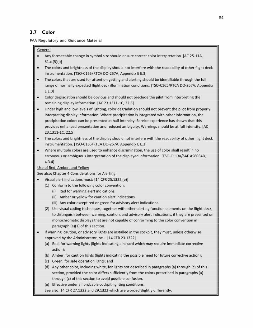
84
3.7 Color
FAA Regulatory and Guidance Material
General • Any foreseeable change in symbol size should ensure correct color interpretation. [AC 25-11A,
31.c.(5)(j)] • The colors and brightness of the display should not interfere with the readability of other flight deck
instrumentation. [TSO-C165/RTCA DO-257A, Appendix E E.3] • The colors that are used for attention getting and alerting should be identifiable through the full
range of normally expected flight deck illumination conditions. [TSO-C165/RTCA DO-257A, Appendix E E.3]
• Color degradation should be obvious and should not preclude the pilot from interpreting the remaining display information. [AC 23.1311-1C, 22.6]
• Under high and low levels of lighting, color degradation should not prevent the pilot from properly interpreting display information. Where precipitation is integrated with other information, the precipitation colors can be presented at half intensity. Service experience has shown that this provides enhanced presentation and reduced ambiguity. Warnings should be at full intensity. [AC 23.1311-1C, 22.5]
• The colors and brightness of the display should not interfere with the readability of other flight deck instrumentation. [TSO-C165/RTCA DO-257A, Appendix E E.3]
• Where multiple colors are used to enhance discrimination, the use of color shall result in no erroneous or ambiguous interpretation of the displayed information. [TSO-C113a/SAE AS8034B, 4.3.4]
Use of Red, Amber, and Yellow See also: Chapter 4 Considerations for Alerting • Visual alert indications must: [14 CFR 25.1322 (e)] (1) Conform to the following color convention: (i) Red for warning alert indications. (ii) Amber or yellow for caution alert indications. (iii) Any color except red or green for advisory alert indications. (2) Use visual coding techniques, together with other alerting function elements on the flight deck,
to distinguish between warning, caution, and advisory alert indications, if they are presented on monochromatic displays that are not capable of conforming to the color convention in paragraph (e)(1) of this section.
• If warning, caution, or advisory lights are installed in the cockpit, they must, unless otherwise approved by the Administrator, be -- [14 CFR 23.1322]
(a) Red, for warning lights (lights indicating a hazard which may require immediate corrective action);
(b) Amber, for caution lights (lights indicating the possible need for future corrective action); (c) Green, for safe operation lights; and
(d) Any other color, including white, for lights not described in paragraphs (a) through (c) of this section, provided the color differs sufficiently from the colors prescribed in paragraphs (a) through (c) of this section to avoid possible confusion.
(e) Effective under all probable cockpit lighting conditions. See also: 14 CFR 27.1322 and 29.1322 which are worded slightly differently.

85
• The primary test for designation of color is: [AC 27-1B, AC 27.1322b(5); AC 29-2C, AC 29.1322a(8)] (i) Red - Is immediate action required? (ii) Amber - Is pilot action (other than immediate) required? (iii) Green - Is safe operation indicated, and is the indication sufficiently distinct to prevent
confusion with the landing gear down indication? (iv) Other advisory lights - Is the meaning clear and distinct enough to prevent confusion with other
annunciations? Do the colors which are utilized differ sufficiently from the colors specified above?
• Use of the colors red, amber, and yellow on the flight deck for functions other than flightcrew alerting must be limited and must not adversely affect flightcrew alerting. [14 CFR 25.1322 (f)]
• For visual alerts on multicolor displays, the colors red, amber, and yellow should be used consistently throughout the flight deck to maintain the effectiveness of an alert. The applicant must limit the use of red, yellow, and amber for functions other than flightcrew alerting, so that misuse does not adversely affect flightcrew alerting per § 25.1322(f). Extensive use of red, yellow, and amber diminishes the attention-getting characteristics of warnings and cautions. This includes alert color consistency among propulsion, flight, navigation, and other displays and indications used on the flight deck. [AC 25.1302-1, 5-5.b.(3)(b)]
• Green is usually used to indicate “normal” conditions; therefore, it is not an appropriate color for an advisory alert. An advisory alert is used to indicate a “non-normal” condition. [AC 25.1322-1, 11.a]
• Green signifies a safe operating condition and more specifically has come to signify landing gear extended and locked. Extensive use of green annunciators throughout the cockpit should generally be avoided due to possible confusion with the special use of green for landing gear. If green annunciators are physically and functionally removed from the landing gear operation, they may be found acceptable for a variety of “safe operating” applications. One such application is “all green for approach,” used in autopilot, flight director, and other navigation system displays. [AC 27-1B CHG 3, AC 27.1322.b.(3); AC 29-2C, AC 29.1322a(6)]
• Displays must either conform to the alert color convention or, in the case of certain monochromatic displays not capable of conforming to the color conventions, use other visual coding techniques per § 25.1322(e). This is necessary so the flightcrew can easily distinguish the alert urgency under all foreseeable operating conditions, including conditions where multiple alerts are provided (§ 25.1322(a)(2)). [AC 25.1322-1, 8.c.(3)]
• Consistent use and standardization for red, amber, and yellow is required to retain the effectiveness of flightcrew alerts. It is important that the flightcrew does not become desensitized to the meaning and importance of color coding for alerts, which could increase the flightcrew’s processing time, add to their workload, and increase the potential for flightcrew confusion or errors. [AC 25.1322-1, 11.f]
• Where red, amber and yellow are proposed for non-flightcrew alerting functions, substantiate that there is an operational need to use these colors to provide safety related awareness information. Examples of acceptable uses of red, amber, or yellow for non-alerting functions include: [AC 25.1322-1, 11.g]
- Weather radar display (for areas of severe/hazardous weather conditions that should be avoided);
- TAWS terrain display (for local terrain relative to the current altitude). See also: Chapter 4 Considerations for Alerting • Compliance with this requirement is typically shown by a description of each of the warning, caution,
and advisory lights (or their electronic equivalents). Evaluations may also be useful to verify the

86
chromaticity (for example, red looks red, amber looks amber) and discriminability (i.e., colors can be distinguished reliably from each other) of the colors being used, under the expected lighting levels. These evaluations can be affected by the specific display technology being used, so final evaluation with flight quality hardware is sometimes needed. A description of a well-defined color coding philosophy, which is consistently applied across flight deck systems, can be used to show how the design avoids “possible confusion”. [PS-ANM100-01-03A, Appendix A, 3]
See also: PS-ACE100-2001-004, Appendix A which is worded slightly differently. Use of Blue • The use of pure blue should not be used for important information because it has low luminance on
many display technologies (for example, CRT and LCD). [AC 25-11A, 31.c.(5)(i)] • Blue should be avoided because it is difficult for the human eye to bring blue symbols into focus and
to distinguish the color from yellow when the symbols are small. [TSO-C146c/RTCA DO-229D, 2.2.1.1.4.2]
• Pure blue should not be used for the display of small, detailed symbols. [TSO-C165/RTCA DO-257A, Appendix E E.3]
• Red and blue should not be presented adjacent to each other more than momentarily. [TSO-C165/RTCA DO-257A, Appendix E E.3]
Consistency of Colors • A common color philosophy across the flightdeck is desirable, although deviations may be approved
with acceptable justification. [AC 25.1302-1, 5-5.b.(3)(a)] • Before defining the color standard for a specific display, establish a consistent color philosophy
throughout the display. [AC 23.1311-1C, 22.1] • Where appropriate, color assignment should be consistent with other color displays in the panel. [AC
23.1311-1C, 22.5] • To ensure correct information transfer, the consistent use and standardization of color is highly
desirable. In order to avoid confusion or interpretation error, there should not be a change in how the color is perceived over all foreseeable conditions. Colors used for one purpose in one information set should not be used for an incompatible purpose that could create a misunderstanding within another information set. [AC 25-11A, 31.c.(5)(b)]
• When overlaying two or more functions, using the same or similar color to convey different information is not recommended. If the same or similar colors are required, then retain the meaning of the different information. [AC 23.1311-1C, 17.12.a] See also: Chapter 3.8 Integrated Display Issues
• Inconsistencies in the use of color should be evaluated to ensure that they are not susceptible to confusion or errors, and do not adversely impact the intended function of the system(s) involved. [AC 25-11A, 31.c.(5)(b)]
See also: Chapter 8 Intended Function • The color-coding scheme employed for the airplane display should be evaluated for consistency with
those recommended in AC 23.1311-1A. The effective use of color can greatly aid in pilot recognition and interpretation of displayed information. It is important that the use of color in all cockpit applications be consistent across all cockpit displays. The chosen colors should be evaluated to determine if they do in fact enhance the understanding of displayed information. Colors should minimize display interpretation errors. [PS-ACE100-2001-004, Appendix A] Author’s Note: See Examples

87
Color-Coding • Aviation conventions should be observed when using colors for coding. [TSO-C146c/RTCA DO-229D,
2.2.1.1.4.2] • Avoid using many different colors to convey meaning on displays. [AC 25.1302-1, 5-5.b.(3)(a). AMC
25.1302, 5.4.2.d] • No more than six colors should be used for color-coding on the display. [TSO-C165/RTCA DO-257A,
2.1.6] See also: AC 25-11A, 31.c.(5)(c), SAE ARP4032B, 4.2.2.1, and Chandra, et al., 2003, which are worded
slightly differently; RTCA DO-256, 2.1.3.6 Notes: [TSO-C165/RTCA DO-257A, 2.1.6] 1. Use of additional colors for other purposes should not detract from the discriminability of
colors used for coding. 2. This restriction on the number of colors may not apply to information shared with the
Electronic Map Display such as terrain and weather. • Other graphic depictions such as terrain maps and synthetic vision presentations may use more than
six colors and use color blending techniques to represent colors in the outside world or to emphasize terrain features. These displays are often presented as background imagery and the colors used in the displays should not interfere with the flightcrew interpretation of overlaid information parameters. [AC 25-11A, 31.c.(5)(d)]
• The following color pairs should be avoided: [AC 25-11A, 31.c.(5)(g)] - Saturated red and blue, - Saturated red and green, - Saturated blue and green, - Saturated yellow and green, - Yellow on purple, - Yellow on green, - Yellow on white, - Magenta on green, - Magenta on black (although this may be acceptable for lower criticality items), - Green on white, - Blue on black, and - Red on black. • The chosen colors should be evaluated to determine if they do in fact enhance the understanding of
displayed information. Colors should minimize display interpretation errors. [PS-ACE100-2001-004, Appendix A]
• If color is used for coding task-essential information, use at least one other distinctive coding parameter (e.g., size, shape, label). Whenever possible, color coding should be consistent across all controls and displays. Consider the effect of flight deck lighting on the appearance of the label, and the use of colors throughout the flight deck (i.e., color philosophy). [AC 20-175, 2-7.c]
See also: Chapter 3.1 Electronic Display Information Elements and Features: General; Chapter 6 Controls; Chapter 7 Design Philosophy

88
• Applicants should show the chosen color set is not susceptible to confusion or misinterpretation due to differences in color usage between displays. Improper color coding increases response times for display item recognition and selection, and increases likelihood of errors in situations where the speed of performing a task is more important than accuracy. [AC 25.1302-1, 5-5.b.(3)(c)]
See also: AMC 25.1302, 5.4.2.d which is worded slightly differently. Redundant Use of Color • Color-coded information should be accompanied by another distinguishing characteristic such as
shape, location, or text. [TSO-C165/RTCA DO-257A, 2.1.6] See also: AMC 25.1302, 5.4.2; TSO-C113a/SAE AS8034B, 4.3.4; TSO-C146c/RTCA DO-229D,
2.2.1.1.4.2; RTCA DO-256, 2.1.3.6, which are worded slightly differently. • Color is an enhancement for understanding the display information that leads to performance
improvement, but it should not be the sole means of discrimination of critical information. [AC 23.1311-1C, 22.6]
See also: AMC 25.1302, 5.4.2 which is worded slightly differently. Color Discriminability • Displayed information shall have sufficient luminance contrast and/or color difference to
discriminate between the following as applicable: [TSO-C113a/SAE AS8034B, 4.3.3] a. Between symbols (including characters and/or lines) and the background (ambient or
generated) on which they are overlayed. b. Between various symbols, characters and lines. This shall also include when they overlay
ambient or generated backgrounds. c. Between the generated backgrounds and ambient backgrounds. d. Between the generated backgrounds of various specified colors. • In all cases the luminance contrast and/or color differences between all symbols, characters, lines, or
all backgrounds shall be sufficient to preclude confusion or ambiguity as to information content of any displayed information. When operationally relevant, the color of the information shall be identifiable (e.g., if colors are used for alerting). The manufacturers shall specify the ambient illumination level and illuminate characteristic for which this requirement is met. [TSO-C113a/SAE AS8034B, 4.3.3]
Note: It is not recommended to place a symbol on a background of equal luminance regardless of color differences. Saturated colors are not recommended to be used for background; saturated colors should be saved for smaller items such as symbols, icons, targets, etc. [TSO-C113a/SAE AS8034B, 4.3.3]
See also: Chapter 2.1 Visual Display Characteristics • Displays shall be readable and colors shall be discernable under anticipated lighting conditions. [TSO-
C146c/RTCA DO-229D, 2.2.1.1.4.2] • Luminance and color differences should not be confusing or ambiguous under any operating
ambient illumination conditions. The specific colors should be consistent with change in brightness on the displays over the full range of ambient light conditions. [AC 23.1311-1C, 22.5]
See also: TSO-C113a/SAE AS8034B, 4.3.41 which is worded slightly differently. • Each coded color should have sufficient chrominance separation so it is identifiable and
distinguishable in all foreseeable lighting and operating conditions and when used with other colors. Colors should be identifiable and distinguishable across the range of information element size, shape, and movement. The colors available for coding from an electronic display system should be
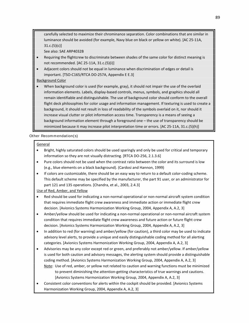
89
carefully selected to maximize their chrominance separation. Color combinations that are similar in luminance should be avoided (for example, Navy blue on black or yellow on white). [AC 25-11A, 31.c.(5)(c)] See also: SAE ARP4032B
• Requiring the flightcrew to discriminate between shades of the same color for distinct meaning is not recommended. [AC 25-11A, 31.c.(5)(i)]
• Adjacent colors should not be equal in luminance when discrimination of edges or detail is important. [TSO-C165/RTCA DO-257A, Appendix E E.3]
Background Color • When background color is used (for example, gray), it should not impair the use of the overlaid
information elements. Labels, display-based controls, menus, symbols, and graphics should all remain identifiable and distinguishable. The use of background color should conform to the overall flight deck philosophies for color usage and information management. If texturing is used to create a background, it should not result in loss of readability of the symbols overlaid on it, nor should it increase visual clutter or pilot information access time. Transparency is a means of seeing a background information element through a foreground one – the use of transparency should be minimized because it may increase pilot interpretation time or errors. [AC 25-11A, 31.c.(5)(h)]
Other Recommendation(s)
General • Bright, highly saturated colors should be used sparingly and only be used for critical and temporary
information so they are not visually distracting. [RTCA DO-256, 2.1.3.6] • Pure colors should not be used when the contrast ratio between the color and its surround is low
(e.g., blue elements on a black background). (Cardosi and Hannon, 1999) • If colors are customizable, there should be an easy way to return to a default color-coding scheme.
This default scheme may be specified by the manufacturer, the part 91 user, or an administrator for part 121 and 135 operations. [Chandra, et al., 2003, 2.4.3]
Use of Red, Amber, and Yellow • Red should be used for indicating a non-normal operational or non-normal aircraft system condition
that requires immediate flight crew awareness and immediate action or immediate flight crew decision. [Avionics Systems Harmonization Working Group, 2004, Appendix A, A.2, 3]
• Amber/yellow should be used for indicating a non-normal operational or non-normal aircraft system condition that requires immediate flight crew awareness and future action or future flight crew decision. [Avionics Systems Harmonization Working Group, 2004, Appendix A, A.2, 3]
• In addition to red (for warning) and amber/yellow (for caution), a third color may be used to indicate advisory level alerts, to provide a unique and easily distinguishable coding method for all alerting categories. [Avionics Systems Harmonization Working Group, 2004, Appendix A, A.2, 3]
• Advisories may be any color except red or green, and preferably not amber/yellow. If amber/yellow is used for both caution and advisory messages, the alerting system should provide a distinguishable coding method. [Avionics Systems Harmonization Working Group, 2004, Appendix A, A.2, 3]
Note: Use of red, amber, or yellow not related to caution and warning functions must be minimized to prevent diminishing the attention-getting characteristics of true warnings and cautions. [Avionics Systems Harmonization Working Group, 2004, Appendix A, A.2, 3]
• Consistent color conventions for alerts within the cockpit should be provided. [Avionics Systems Harmonization Working Group, 2004, Appendix A, A.2, 3]

90
Use of Blue • Pure (e.g., “royal”) blue should not be used for text, small symbols, other fine detail, or as a
background color (See DOT/FAA/AR-99/52). [RTCA DO-256, 2.1.3.6] • Saturated red and blue should never be presented in close proximity to avoid a false perception of
depth. [RTCA DO-256, 2.1.3.6; Cardosi and Hannon, 1999] Consistency of Colors • If information is color-coded, other use of a color in the coding scheme should be minimized so that
the relevant color-coding is not misinterpreted. (Garner and Assenmacher, 1997; Smith and Mosier, 1986)
• Colors used on raster aeronautical charts (RACs) should closely approximate the colors depicted on the paper chart.
Color-Coding • Color-coding should be consistent across all system displays and controls. [RTCA DO-256, 2.1.3.6] • When colors are assigned a meaning, each color should have only one meaning. [RTCA DO-256
2.1.3.6] • The color of controls should be black or gray. (McAnulty, 1995; MIL-STD-1472G, 5.1.1.4.5.a) • Redundant Use of Color • Whenever color is used to code information, it shall be used redundantly with another means of
coding information. [RTCA DO-256, 2.1.3.6] Note: All information conveyed by color coding should also be available under a monochrome
presentation. [RTCA DO-256, 2.1.3.6] Color Discriminability • If color is used for information coding, the selected color set shall be absolutely discriminable (i.e.,
can be identified) under the full range of normally expected ambient light conditions. [RTCA DO-256, 2.1.3.6]
• Color discrimination is easier for large display objects than small ones. If color discrimination is necessary, symbols and display elements may need to be presented at a larger size or character height than what is recommended by the minimum. (Cardosi and Murphy, 1995; Smith and Mosier, 1986)
Background
Color can enhance understanding of information, particularly in complex, dense displays. It may be used to aid visual search or to perceptually tie together display elements which are spatially separated on the display. For example, use of color to code information reduces search times in densely populated displays when compared with performance obtained using size, shape, or brightness coding. Color-coding is most effective if the intended meaning of the coding is unambiguous and immediately understood, e.g., when color is a natural representation of the information or conforms to pilot stereotypes. However, color has a high potential for distraction, so overuse of color can increase the appearance of visual clutter and reduce display legibility. This leads to longer visual search times and the risk of misinterpretation. Color-coding that requires pilot to learn and memorize its meaning increases training time and imposes a burden on memory, so in these cases, the number of color codes that can be used may be less than the number that can be detected and discriminated. A proliferation of color sets can reduce safety; the appropriate number of colors that should be used will depend on the implementation.
It is important that color be used redundantly when it codes information; that is, there should be some other indication about the information that the color is used to convey. Color vision deficiencies (that is, “color

91
blindness”) affect approximately nine percent of the population (i.e., eight percent of men and 0.5 percent of women). The Aeromedical Certification Statistical Handbook (Table V.C.) estimates that there were 16,493 male and 47 female active airmen with color vision deficiencies as of December 31, 1998, with 2,317 of these holding first class medicals, 3,871 holding second class medicals, and 10, 352 holding third class medicals. (These estimates are based on active airmen who were certified within the 25 months prior to December 31, 1998, and were assigned the restriction “Not Valid for Night Flying by Color Signal Control” or issued a waiver for deficient color vision; see N 8110.98.) Additionally, color perception varies across individuals. Normal aging of the eye reduces the ability to distinguish between colors as the color-sensitive cells in the eye become less sensitive and the lens begins to yellow. Consequently, the eye loses the ability to focus on red objects and differentiate between blue and green and light blues appear even lighter. In particular, pure blue is problematic for observers over age 50.
Colors need to be selected carefully to ensure that they are sufficiently different and easily discriminable from each other to reduce the probability of misinterpretation. Color discrimination can be compromised by a variety of factors, such as the lighting conditions in the flight deck, the display position, the display quality, and viewing angle. The more colors that are used, the closer in hue each color will be and the harder it will be to discriminate between them (Cardosi and Murphy, 1995; Smith and Mosier, 1986).
AC 25-11A defines chromaticity as “color characteristic of a symbol or image defined by its u’, v’ coordinates” (see AC 25-11A, Appendix 3). These coordinates can be used to develop a graphical representation of all colors, as shown by the CIE chromaticity diagram below. In the diagram, the distance between two colors is a direct reflection of the perceptual difference between those two colors, so colors that are widely spaced apart will appear more different from one another. For more information about how to use the CIE color space to select colors that are most likely to be discriminable from one another, see the Commissions Internationale de L’Eclairage publication number 15.3, Colorimetry (2004).

92
Contrasting basic colors will help to differentiate between display elements better than selecting colors that are near each other in a color table. Additionally, bright or saturated colors can draw attention to the display, but they can cause eyestrain and/or afterimages. In particular, binocular rivalry may be a consequence of presenting a highly saturated red display element close to a highly saturated blue one (AC 23.1311-1C; Ahlstrom and Longo, 2003).
The consistent use of color within an application and across all flight deck displays is highly desirable. There are a number of long-established color conventions for aircraft displays, in particular, the use of red and yellow/amber is typically reserved for alerting functions (that is, warnings and cautions, respectively). 14 CFR 23.1322, 25.1322, 27.1322, 29.1322 establishes conventions for the use of red and amber/yellow on the flight deck. If red and yellow/amber are used too broadly, pilots may become desensitized to their meaning and not be able to recognize situations quickly where their actions are time-critical. Additionally, inconsistent use of red and amber/yellow can lead to difficulty interpreting the meaning of the colors when they appear, resulting in a slower response and increasing the potential for a more significant error (Boucek, Veitengruber, and Smith, 1977; Widdell and Post, 1992; Veitengruber, Boucek, and Smith, 1977).
Example(s)
One way to ensure that colors are used redundantly with other cues is to design the system for a monochrome display first, and then add color afterwards (CAP 708).
High color confusion exists between magenta and red, magenta and purple, yellow and amber, and cyan and green (RTCA DO-257A, Appendix E).
A set of examples of how color may be used is provided in Table 3.7.1, which shows previously accepted color-coding and the functional meaning associated with the color.

93
Table 3.7.1. Recommended colors for certain functions. [AC 25-11A, 31.c.(5)(e)]
Function Color
Warnings Red
Flight envelope and system limits Red or Yellow/Amber as appropriate
Cautions, abnormal sources Amber/Yellow
Earth Tan/Brown
Scales and associated figures White
Engaged modes/normal conditions Green*
Earth Tan/Brown
Sky Cyan/Blue
ILS deviation pointer Magenta
Flight director bar Magenta/Green
Pilot selectable references (bugs) Magenta
Divisor lines, units and labels for inactive soft buttons
Light Gray
* Use of the color green for tape elements (for example airspeed and altitude) has also been found acceptable if the color green does not adversely affect flightcrew alerting.
The FAA Advisory Circular on Electronic Displays (AC 25-11A) provide examples of what display features that should be allocated a color using Color Set 1 or Color Set 2, as seen in Table 3.7.2 below.
Table 3.7.2. Specified colors for certain display features. [AC 25-11A, 31.c.(5)(f); AC 23.1311-1C, 22.3]
Display Feature Color Set 1 Color Set 2
Fixed reference symbols, that is, lubber lines White Yellow*
Current data, values White Green
Armed modes White Cyan
Selected data, values Green Cyan
Selected heading Magenta** Cyan
Active route/flight plan Magenta White
* The extensive use of the color yellow for other than caution/abnormal information is discouraged. **In color set 1, magenta is associated with those analog parameters that constitute "fly to" or "keep centered" type
information.
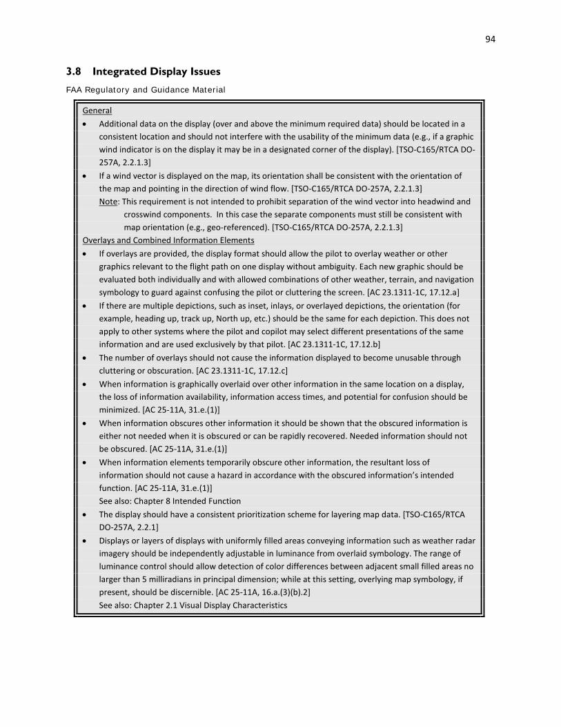
94
3.8 Integrated Display Issues
FAA Regulatory and Guidance Material
General • Additional data on the display (over and above the minimum required data) should be located in a
consistent location and should not interfere with the usability of the minimum data (e.g., if a graphic wind indicator is on the display it may be in a designated corner of the display). [TSO-C165/RTCA DO-257A, 2.2.1.3]
• If a wind vector is displayed on the map, its orientation shall be consistent with the orientation of the map and pointing in the direction of wind flow. [TSO-C165/RTCA DO-257A, 2.2.1.3]
Note: This requirement is not intended to prohibit separation of the wind vector into headwind and crosswind components. In this case the separate components must still be consistent with map orientation (e.g., geo-referenced). [TSO-C165/RTCA DO-257A, 2.2.1.3]
Overlays and Combined Information Elements • If overlays are provided, the display format should allow the pilot to overlay weather or other
graphics relevant to the flight path on one display without ambiguity. Each new graphic should be evaluated both individually and with allowed combinations of other weather, terrain, and navigation symbology to guard against confusing the pilot or cluttering the screen. [AC 23.1311-1C, 17.12.a]
• If there are multiple depictions, such as inset, inlays, or overlayed depictions, the orientation (for example, heading up, track up, North up, etc.) should be the same for each depiction. This does not apply to other systems where the pilot and copilot may select different presentations of the same information and are used exclusively by that pilot. [AC 23.1311-1C, 17.12.b]
• The number of overlays should not cause the information displayed to become unusable through cluttering or obscuration. [AC 23.1311-1C, 17.12.c]
• When information is graphically overlaid over other information in the same location on a display, the loss of information availability, information access times, and potential for confusion should be minimized. [AC 25-11A, 31.e.(1)]
• When information obscures other information it should be shown that the obscured information is either not needed when it is obscured or can be rapidly recovered. Needed information should not be obscured. [AC 25-11A, 31.e.(1)]
• When information elements temporarily obscure other information, the resultant loss of information should not cause a hazard in accordance with the obscured information’s intended function. [AC 25-11A, 31.e.(1)]
See also: Chapter 8 Intended Function • The display should have a consistent prioritization scheme for layering map data. [TSO-C165/RTCA
DO-257A, 2.2.1] • Displays or layers of displays with uniformly filled areas conveying information such as weather radar
imagery should be independently adjustable in luminance from overlaid symbology. The range of luminance control should allow detection of color differences between adjacent small filled areas no larger than 5 milliradians in principal dimension; while at this setting, overlying map symbology, if present, should be discernible. [AC 25-11A, 16.a.(3)(b).2] See also: Chapter 2.1 Visual Display Characteristics

95
• Prioritize information according to task criticality. Lower priority information should not mask higher priority information. Higher priority information should be available, readily detectable, easily distinguishable, and usable per § 25.1302(b). [AC 25.1302-1, 5-5.c.(2)(d)] See also: AMC 25.1302, 5.4.3.b which is worded slightly differently.
• When overlaying coded information elements over images, the information elements should be readily identifiable and distinguishable for all foreseeable conditions of the underlying image and range of motion. The information elements should not obscure necessary information contained in the image. The information should be depicted with the appropriate size, shape, and placement accuracy to avoid being misleading. They should retain and maintain their shape, size, and color for all foreseeable conditions of the underlying image and range of motion. [AC 25-11A, 31.g.(4)]
• When fusing or overlaying multiple images, the resultant combined image should meet its intended function despite any differences in image quality, projection, data update rates, sensitivity to sunlight, data latency, or sensor alignment algorithms. When conforming an image to the outside world, such as on a HUD, the image should not obscure or significantly hinder the flightcrew’s ability to detect real world objects. An independent brightness control of the image may help satisfy this guideline. Image elements that correlate or highlight real world objects should be sufficiently coincident to avoid interpretation error or significantly increase interpretation time. [AC 25-11A, 31.g.(5)]
See also: Chapter 8 Intended Function Consistency of Overlays • If information is integrated with other information on a display, the projection, the placement
accuracy, the directional orientation and the display data ranges should all be consistent (for example, when traffic or weather is integrated with navigation information). [AC 25-11A, 31.e.(1)]
See also: TSO-C165/RTCA DO-257A, 2.2.1.3 which is worded slightly differently. • If there are multiple depictions, such as inset, inlays, or overlayed depictions, the orientation (for
example, heading up, track up, North up, etc.) should be the same for each depiction. This does not apply to other systems where the pilot and copilot may select different presentations of the same information and are used exclusively by that pilot. [AC 23.1311-1C, 17.12.b]
See also: TSO-C165/RTCA DO-257A, 2.2.1.3 and SAE ARP5898, 8.3.5 which are worded slightly differently; Chapter 3.5 Graphical Depictions and Images
• Combinations of multiple data presentations shall not cause conflicting interpretation of the symbology or icons. [AC 23.1311-1C, 17.12.c]
• Symbols and colors used for one purpose in one information set should not be used for another purpose within another information set. [TSO-C165/RTCA DO-257A, 2.1.9]
• When overlaying two or more functions, using the same or similar color to convey different information is not recommended. If the same or similar colors are required, then retain the meaning of the different information. [AC 23.1311-1C, 17.12.a]
See also: Chapter 3.7 Color • Where information on the shared display is inconsistent, the inconsistency shall be obvious or
annunciated, and should not contribute to errors in information interpretation. [TSO-C165/RTCA DO-257A, 2.1.9]

96
• To meet the requirements in § 25.1302(b) applicants should show that layering information on a display does not add to confusion and clutter as a result of the color standards and symbols used.
Avoid designs requiring flightcrew members to manually reduce the clutter of such displays. [AC 25.1302-1, 5-5.b.(3)(e)]
See also: AMC 25.1302, 5.4.2.d which is worded slightly differently. • While strongly encouraged, the FAA recognizes it is not always possible to provide a consistent
flightcrew interface. Despite conformance with a flightdeck design philosophy, principles of consistency, etc., it is possible to negatively impact flightcrew workload. As an example, all the auditory alerts in a design may adhere to a flightdeck alerting philosophy, but the number of alerts may be unacceptable. Consistent format across the flightdeck may not work when individual task requirements necessitate presentation of data in two significantly different formats. An example is a weather radar display formatted to show a sector of the environment, while a moving map display shows a 360 degree view. In such cases, the applicant should show that the interface design is compatible with the requirements of the piloting task and that it can be used individually and in combination with other interfaces without interference to either system or function. Additionally: [AC 25.1302-1, 5-8.c.(1)]
(a) The applicant should provide an analysis identifying each piece of information or data presented in multiple locations and show the data are presented in a consistent manner or, where that is not true, justify why that is not appropriate.
(b) Where information is inconsistent, the inconsistency should be obvious or annunciated, and should not contribute to errors in information interpretation.
(c) The applicant should provide a rationale for instances where a system’s design diverges from the flightdeck design philosophy. Consider any impact on workload and errors as a result of this divergence.
(d) The applicant should describe what conclusion the flightcrew is expected to draw and what action should be taken when information on the display conflicts with other information on the flightdeck either with or without a failure.
See also: AMC 25.1302, 5.7.3 which is worded slightly differently. Time Sharing See also: Chapter 5.2 Managing Display Information • Any information that should or must be continuously monitored by the flightcrew should be
displayed at all times. [AC 25-11A, 31.e.(2)] • Whether or not information may be time shared depends on how easily it can be retrieved in
normal, non-normal, and emergency operations. Information for a given performance monitoring task may be time shared if the method of switching back and forth does not jeopardize the performance monitoring task. [AC 25-11A, 31.e.(2)]
• Generally, system information, planning, and other information not necessary for the pilot tasks can be time shared. [AC 25-11A, 31.e.(2)]
Separating Information Visually • When different information elements are adjacent to each other on a display, the elements should
be separated visually so the pilots can easily distinguish between them. Required information presented in reversionary or compacted display modes following a display failure should still be uncluttered and still allow acceptable information access time. [AC 25-11A, 31.e.(3)]
• Visual separation can be achieved with, for example, spacing, delimiters, or shading in accordance with the overall flight deck information management philosophy. [AC 25-11A, 31.e.(3)]

97
• Patterning, bordering, or blanking may be used to clearly depict the different sets of data. [AC 23.1311-1C, 17.12.a]
Clutter/Declutter • To reduce flight crewmember’s interpretation time, equipment should present information simply
and in a well-ordered way. Applicants should show that an information delivery method, whether visual or auditory, presents the information the flight crewmember actually needs to perform the task at hand. The flightcrew can use their own discretion to limit the amount of information presented at any point in time. [AC 25.1302-1, 5-5.c.(2)(a)] See also: AMC 25.1302, 5.4.3.b which is worded slightly differently.
• Information should be displayed so that clutter is minimized. [AC 25-11A, 31.e.(4)(a)] • To enhance pilot performance a means should be considered to declutter the display. [AC 25-11A,
31.e.(4)(b)] • When a design allows flightcrew selection of additional information, the basic display modes should
remain uncluttered. [AC 25.1302-1, 5-5.c.(2)(a); AMC 25.1302, 5.4.3.b] • Deselection of shared information (e.g., weather, terrain, etc.) should be possible to declutter the
display or enhance readability. [TSO-C165/RTCA DO-257A, 2.1.9] • If additional map information has been selected for display, it should be possible to deselect all
displayed additional information as a set. [TSO-C165/RTCA DO-257A, 2.2.1.3] • It should be possible for the pilot to accomplish this declutter function with a single action. [TSO-
C165/RTCA DO-257A, 2.2.1.3] • If equipment uses automatic de-selection of data to enhance the flight crewmember’s performance
in certain emergency conditions, the applicant must show, per § 25.1302(a), that it provides the information the flight crewmember needs. The use of part-time displays depends not only on the removal of clutter from the information, but also on the availability and criticality of the display. Therefore, when designing such features, the applicant should follow the guidance in AC 2511A, Electronic Flight Control Displays. [AC 25.1302-1, 5-5.c.(2)(b)] See also: AMC 25.1302, 5.4.3.b which is worded slightly differently.
• The density of information on the display should be compatible with the pilot's ability to recognize essential information and to minimize misinterpretation. Symbols and markings that are displayed during specific phases of flight may be removed at other times to reduce clutter. Establish an information prioritization scheme to ensure the clear presentation of essential information. [AC 23.1311-1C, 17.3]
See also: Section 3.4 Markings, Dials, Tapes, and Numeric Readouts • Clutter should be a major consideration during the reversionary or compacted modes. When
combining essential information on a display after another display or unit fails, the display format should not be confusing and the information should still be usable, including unusual attitude. If clutter is anticipated, provide a means to manually remove the clutter (decluttering). Automatic decluttering, such as during specific phases of flight, or during certain alerts, may also be appropriate. [AC 23.1311-1C, 17.3] See also: Chapter 5.3 Reversionary Displays, Display Reconfiguration, and Managing Display Failure
• The PFD may require an automatic declutter function during unusual attitudes. Unusual attitudes generally exceed 70 degrees of bank or +/-30 degrees of pitch, but may vary with airplane performance. The approved configuration (whether basic-T configuration or a new configuration) should be preserved. Basic navigation information on the primary navigation display does not need

98
to be decluttered. Flight guidance displayed to assist in unusual attitude recovery should be red and point to the correct direction for proper recovery. SVS information on the display may need to be removed if the attitude source is no longer available. [AC 23.1311-1C, 17.4.b.]
Other Recommendation(s)
General • Sets of data that are associated with specific questions or related to particular functions shall be
grouped together to signify those functional relationships. [MIL-STD-1472G, 5.2.2.2.6.a.(3)] Overlays and Combined Information Elements • A prioritization scheme may be needed that defines which data categories have priority if dynamic
display elements temporarily overlay and obscure other display elements. (Smith and Mosier, 1986) Consistency of Overlays • If information is integrated with other information on a display, the update rate should be
consistent. See also: Chapter 2.1 Visual Display Characteristics Time Sharing • The pilot should be able to switch between functions easily. (Chandra, et al., 2003) • The current task should be identified easily. (Chandra, et al., 2003) Decluttering • If there is a declutter capability, it should not be possible for the pilot to remove safety critical
display elements (e.g., terrain, obstructions, or special use airspace) without knowing that they are suppressed. If such information can be decluttered, it should not be possible for the pilot to believe that it is not visible because it is not there. [Chandra, et al., 2003, 6.2.11]
• Display elements in any decluttering scheme should be organized to conform to pilot’s expectations. • The decluttering scheme should be documented in the pilots’ guide and in the certification plan.
(Yeh, 2004)
Background
Multiple types of information, such as weather, traffic, terrain, or obstacle depictions, may be shown simultaneously to increase the utility of a display. This information may be presented with a basic map display, e.g., using layers on the same display surface, or in some cases the information may temporarily replace it, e.g., if information is time-shared so that it is shown one at a time. Information may also be combined in separate windows on several areas of one large display. The appropriate format will depend on the task, and not all information can be presented on a shared display. Inconsistency in display orientation, scale, symbols or colors when information is shared could compromise the usefulness of the display system and could increase workload, head-down time, and the potential for error.
Presenting related information close together on one page or on an integrated display can implicitly convey relationships. There are several methods for organizing displays. One is by importance; for example, information and displays showing primary flight information are grouped together in the pilot’s primary field-of-view. Another method is to group by function, such that information and displays used together for a specific operation or that are related to a system component are located together in one area. A third method is to group by sequence, so that information and displays are grouped and arranged according to the order in which they are used. Generally, the sequence is from top to bottom or right to left. These methods may be combined; for example, displays may be arranged globally by function but within a functional group,

99
information can be arranged by sequence of use, logical flow, or importance (Avery, et al., 1999; MIL-STD-1472G; Wickens, Gordon, and Liu, 1998).
Several different types of information may be overlaid onto a display, and the display can become cluttered very easily. In particular, features of the display could be hidden by the overlays and interfere with task performance. Decluttering has the advantage of temporarily removing unnecessary information from view. However, when information is not visible, the pilot may not remember it is available and fail to consider it when it is relevant. Too much flexibility, e.g., having too many levels of decluttering, could also increase the complexity of the interaction. The implementation of decluttering should consider pilot’s expectations, the phase of flight, and the tasks to be performed. Otherwise, the time needed to retrieve information and the potential for error increases.
AC 25-11A defines time sharing as “showing different information in the same display area at different times”. On some aircraft, one display system may be used to set the parameters for a number of systems on the flight deck. Consequently, too much task switching may be required; for example, even the simple task of changing communication frequencies could require the pilot to stop the current tasks in order to find and switch to the appropriate display page. Interruptions to ongoing tasks may lead pilots to lose their place, thereby introducing the potential for error. Information that must be monitored continuously may not be time-shared easily because the pilot would need to switch back and forth between the sources of information on the shared display, and this could be detrimental to performance on the monitoring task.
Example(s)
One way to prevent necessary information from being obscured when overlaying information is to protect certain areas of the display so that information does not overlap.
One way to indicate which window is active when there are multiple display windows is to highlight the borders of the active window.

This page left blank intentionally.
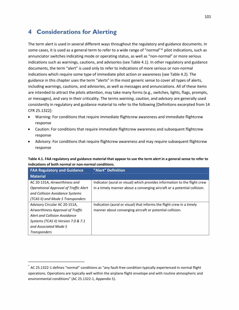
101
4 Considerations for Alerting
The term alert is used in several different ways throughout the regulatory and guidance documents. In some cases, it is used as a general term to refer to a wide range of “normal”* pilot indications, such as annunciator switches indicating mode or operating status, as well as “non-normal” or more serious indications such as warnings, cautions, and advisories (see Table 4.1). In other regulatory and guidance documents, the term “alert” is used only to refer to indications of more serious or non-normal indications which require some type of immediate pilot action or awareness (see Table 4.2). The guidance in this chapter uses the term “alerts” in the most generic sense to cover all types of alerts, including warnings, cautions, and advisories, as well as messages and annunciations. All of these items are intended to attract the pilots attention, may take many forms (e.g., switches, lights, flags, prompts, or messages), and vary in their criticality. The terms warning, caution, and advisory are generally used consistently in regulatory and guidance material to refer to the following [Definitions excerpted from 14 CFR 25.1322]: • Warning: For conditions that require immediate flightcrew awareness and immediate flightcrew
response • Caution: For conditions that require immediate flightcrew awareness and subsequent flightcrew
response • Advisory: For conditions that require flightcrew awareness and may require subsequent flightcrew
response Table 4.1. FAA regulatory and guidance material that appear to use the term alert in a general sense to refer to indications of both normal or non-normal conditions.
FAA Regulatory and Guidance Material
“Alert” Definition
AC 20-131A, Airworthiness and Operational Approval of Traffic Alert and Collision Avoidance Systems (TCAS II) and Mode S Transponders
Indicator (aural or visual) which provides information to the flight crew in a timely manner about a converging aircraft or a potential collision.
Advisory Circular AC 20-151A, Airworthiness Approval of Traffic Alert and Collision Avoidance Systems (TCAS II) Version 7.0 & 7.1 and Associated Mode S Transponders
Indication (aural or visual) that informs the flight crew in a timely manner about converging aircraft or potential collision.
* AC 25.1322-1 defines “normal” conditions as “any fault-free condition typically experienced in normal flight operations. Operations are typically well within the airplane flight envelope and with routine atmospheric and environmental conditions” (AC 25.1322-1, Appendix 5).

102
FAA Regulatory and Guidance Material
“Alert” Definition
AC 20-138C, Airworthiness Approval of Positioning and Navigation Systems
AC 20-138C does not specifically design the term “alert”, but the term appears to be used generically as in the example below: “Aircraft with ILS capability that is interfaced to GPWS or Class A TAWS (Mode 5 GPWS) alert for ILS deviations below the ILS glideslope must also include a glideslope alerting function during a GPS/SBAS LPV approach. It is desirable to provide an alerting function on any GPS/SBAS approach with vertical guidance.” [Section 14-6.8.a]
Advisory Circular AC 23-18, Installation of Terrain Awareness
Alert: A visual, aural, or tactile stimulus presented to either attract attention or convey information regarding system status or condition, or both. Aural Alert: A discrete sound, tone, or verbal statement used to annunciate a condition, situation, or event.
Advisory Circular AC 25-23, Airworthiness Criteria for the Installation Approval of a Terrain Awareness and Warning System (TAWS) for Part 25 Airplanes
A visual, aural, or tactile stimulus presented either to attract attention or to convey information regarding system status or condition, or both Aural Alert: A discrete sound, tone, or verbal statement used to enunciate a condition, situation, or event.
TSO-C151c, Terrain Awareness and Warning System (TAWS)
Alert: A visual, aural, or tactile stimulus presented to attract attention and convey information regarding system status or condition. Aural Alert: A discrete sound, tone, or verbal statement used to annunciate a condition, situation, or event.
AC 27-1B, Certification of Normal Category Rotorcraft A visual or aural stimulus presented either to attract attention or to
convey information regarding system status or condition, or both. AC 29-2C Certification of Transport Category Rotorcraft TSO-C146c /RTCA DO-229D For the definitions of missed alert, false alert, and time-to-alert, an
alert is defined to be an indication that is provided by the GPS/SBAS equipment when the positioning performance achieved by the equipment does not meet the integrity requirements. This alert is one of the conditions that would cause a navigation alert. [1.7.3]

103
Table 4.2. FAA regulatory and guidance material that use the term alert to refer only to indications of more serious or non-normal conditions.
FAA Regulatory and Guidance Material
“Alert” Definition
AC 25-11A, Electronic Flight Deck Displays
A generic term used to describe a flight deck indication meant to attract the attention of and identify to the flightcrew a non-normal operational or airplane system condition. Warnings, Cautions, and Advisories are considered to be alerts.
AMC 25.1302, Installed Systems and Equipment for Use by the Flight Crew∗
A generic term used to describe a flight deck indication meant to attract the attention of the flight crew, and identify to them a non-normal operational or aeroplane system condition. Warnings, Cautions, and Advisories are considered to be alerts. (Reference definition in AMC 25.1322)
AC 25.1322-1, Flightcrew Alerting A generic term used to describe a flight deck indication meant to attract the attention of and identify to the flightcrew a non-normal operational or airplane system condition. Alerts are classified at levels or categories corresponding to Warnings, Cautions, and Advisories. Alert indications also include nonnormal range markings (for example, exceedences on instruments and gauges.)
AC 25.1329-1B, Approval of Flight Guidance Systems
A generic term used to describe a flight deck indication meant to attract the attention of the flightcrew to a nonnormal operational or airplane system condition without implying the degree or level of urgency for recognition and corrective action by the crew. Warnings, cautions, and advisories are considered alerts.
∗ Note that AC 25.1302-1 does not define the term “alert”.

104
4.1 General
FAA Regulatory and Guidance Material
General • Flightcrew alerts must: [14 CFR 25.1322 (a)] (1) Provide the flightcrew with the information needed to: (i) Identify non-normal operation or airplane system conditions, and (ii) Determine the appropriate actions, if any. (2) Be readily and easily detectable and intelligible by the flightcrew under all foreseeable operating
conditions, including conditions where multiple alerts are provided. (3) Be removed when the alerting condition no longer exists. • Alerting messages should differentiate between normal and abnormal indications. [AC 23.1311-1C,
18.3] • Only non-normal airplane-system conditions and operational events that require flightcrew
awareness to support flightcrew decision making and facilitate the appropriate flightcrew response should cause an alert. However, conditions that require an alert depend on the specific system and airplane design, and overall flight-deck philosophy. [AC 25.1322-1, 5.c.(1)]
• Conditions that do not require flightcrew awareness should not generate an alert. [AC 25.1322-1, 5. a]
• The number and type of alerts required should be determined by the unique situations that are being detected and by the crew procedures required to address those situations. [AC 25.1329-1B, 45.d.(2)]
• Provide individual alerts for each function essential for safe operation. [AC 23.1311-1C, 18.3] • Alerting conditions. Establish how airplane system conditions or operational events that require an
alert (for example, engine overheating, windshear, etc.), will be determined. [AC 25.1322-1, 5.c.(9)] • Annunciations should only be indicated while the condition exists. [AC 25-11A, 31.f.(1)(b)] • Annunciations and indications should be operationally relevant and limited to minimize the adverse
effects on flightcrew workload. [AC 25-11A, 31.f.(1)(a)] • The equipment shall provide the capability to test all external annunciators. [TSO-C146c/RTCA DO-
229D, 2.2.1.5.1] • Timely alerts for each phase of flight should be provided when any operating limit is reached or
exceeded for the required powerplant parameter. [AC 23.1311-1C, 9.3.b] • An alert should be given when the information presented to the flightcrew is no longer meeting the
required integrity level, in particular when there is a single sensor or loss of independence. [AC 25-11A, 36.e.(2)(f)]
• The latency period induced by the display system, particularly for alerts, should not be excessive and should take into account the criticality of the alert and the required crew response time to minimize propagation of the failure condition. [AC 25-11A, 21.e.(8)]
• Design of Controls, Indications, and Alerts. These features must be designed to minimize flightcrew errors and confusion. [See § 25.1329(i)] Indications and alerts should be presented in a manner compatible with the procedures and assigned tasks of the flightcrew and provide the necessary information to perform those tasks. The indications must be grouped and presented in a logical and consistent manner and should be visible from each pilot’s station under all expected lighting conditions. [See § 25.1329(i)] The choice of colors, fonts, font size, location, orientation, movement, graphical layout, and other characteristics—such as steady or flashing—should all contribute to the

105
effectiveness of the system. Controls, indications, and alerts should be implemented in a consistent manner. [AC 25.1329-1B, 42.b]
See also: Chapter 9 Error Management, Prevention, Detection, and Recovery Alerting Philosophy • When developing a flightcrew-alerting system use a consistent philosophy for alerting conditions,
urgency and prioritization, and presentation. [AC 25.1322-1, 5.b] • Annunciations and indications should be clear, unambiguous, timely, and consistent with the flight
deck design philosophy. [AC 25-11A, 31.f.(1)(b)] See also: AC 27-1B, Chapter 3 AC 27 MG 18, g.(7) and AC 29-2C, Chapter 3 AC 29 MG 18, g.(7) which
are worded slightly differently. • The alerting philosophy should describe the format and content for visual information. Use
consistent format and content That includes the following three elements: [AC 25.1322-1, Appendix 1, 2.b.(2)]
- The general heading of the alert (for example, HYD, FUEL) - The specific subsystem or location (for example, L-R, 1-2), - The nature of the condition (for example, FAIL, HOT, LOW) • Use a consistent philosophy for the format and content of the visual information to clearly indicate
both the alert meaning and condition. The objectives of the corresponding text message format and content are to direct the flightcrew to the correct checklist procedure, and to minimize the risk of flightcrew error. [AC 25.1322-1, Appendix 1, 2.b1)]
• Use logic-based integrated alerting systems to ensure that alerting system elements are synchronized and provide the proper alert presentation format for each urgency level. [AC 25.1322-1, 5.c.(5)]
• Establish a consistent alert presentation scheme (for example, location of the alert on the flight deck, alert combinations [aural, visual, tactile], information presented in the alert message, and color and graphical coding standardization). Also, determine the format in which that alert will be presented (for example, structure and timing of alert messages) to support the alerting function’s purpose. [AC 25.1322-1, 5.c.(11)]
• While strongly encouraged, the FAA recognizes it is not always possible to provide a consistent flightcrew interface. Despite conformance with a flightdeck design philosophy, principles of consistency, etc., it is possible to negatively impact flightcrew workload. As an example, all the auditory alerts in a design may adhere to a flightdeck alerting philosophy, but the number of alerts may be unacceptable. [AC 25.1302-1, 5-8.c.(1)]
See also: AMC 25.1302, 5.7.3 which is worded slightly differently. Field-of-View/Location See also: Chapter 2.3 Field-of-View • In most applications, critical information that is considered to be essential for safe flight, with
warning or cautionary information that requires immediate pilot action or awareness, should be placed in the primary field-of-view. [AC 23.1311-1C, 15.2]
• Some annunciations may be acceptable within 35 degrees if they are associated with a unique aural tone or a master warning/caution annunciations that is within 15 degrees and with a pilot evaluation. [AC 23.1311-1C, 15.4, Note 4]
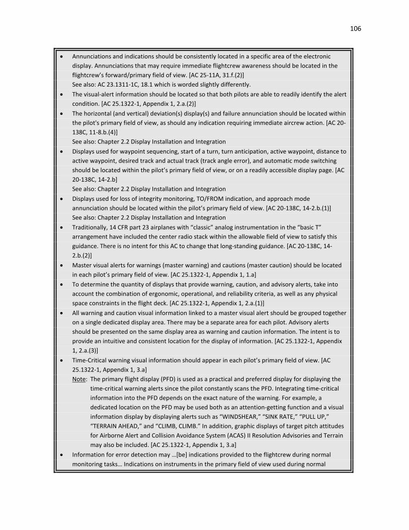
106
• Annunciations and indications should be consistently located in a specific area of the electronic display. Annunciations that may require immediate flightcrew awareness should be located in the flightcrew’s forward/primary field of view. [AC 25-11A, 31.f.(2)]
See also: AC 23.1311-1C, 18.1 which is worded slightly differently. • The visual-alert information should be located so that both pilots are able to readily identify the alert
condition. [AC 25.1322-1, Appendix 1, 2.a.(2)] • The horizontal (and vertical) deviation(s) display(s) and failure annunciation should be located within
the pilot's primary field of view, as should any indication requiring immediate aircrew action. [AC 20-138C, 11-8.b.(4)] See also: Chapter 2.2 Display Installation and Integration
• Displays used for waypoint sequencing, start of a turn, turn anticipation, active waypoint, distance to active waypoint, desired track and actual track (track angle error), and automatic mode switching should be located within the pilot’s primary field of view, or on a readily accessible display page. [AC 20-138C, 14-2.b]
See also: Chapter 2.2 Display Installation and Integration • Displays used for loss of integrity monitoring, TO/FROM indication, and approach mode
annunciation should be located within the pilot’s primary field of view. [AC 20-138C, 14-2.b.(1)] See also: Chapter 2.2 Display Installation and Integration • Traditionally, 14 CFR part 23 airplanes with “classic” analog instrumentation in the “basic T”
arrangement have included the center radio stack within the allowable field of view to satisfy this guidance. There is no intent for this AC to change that long-standing guidance. [AC 20-138C, 14-2.b.(2)]
• Master visual alerts for warnings (master warning) and cautions (master caution) should be located in each pilot’s primary field of view. [AC 25.1322-1, Appendix 1, 1.a]
• To determine the quantity of displays that provide warning, caution, and advisory alerts, take into account the combination of ergonomic, operational, and reliability criteria, as well as any physical space constraints in the flight deck. [AC 25.1322-1, Appendix 1, 2.a.(1)]
• All warning and caution visual information linked to a master visual alert should be grouped together on a single dedicated display area. There may be a separate area for each pilot. Advisory alerts should be presented on the same display area as warning and caution information. The intent is to provide an intuitive and consistent location for the display of information. [AC 25.1322-1, Appendix 1, 2.a.(3)]
• Time-Critical warning visual information should appear in each pilot’s primary field of view. [AC 25.1322-1, Appendix 1, 3.a]
Note: The primary flight display (PFD) is used as a practical and preferred display for displaying the time-critical warning alerts since the pilot constantly scans the PFD. Integrating time-critical information into the PFD depends on the exact nature of the warning. For example, a dedicated location on the PFD may be used both as an attention-getting function and a visual information display by displaying alerts such as “WINDSHEAR,” “SINK RATE,” “PULL UP,” “TERRAIN AHEAD,” and “CLIMB, CLIMB.” In addition, graphic displays of target pitch attitudes for Airborne Alert and Collision Avoidance System (ACAS) II Resolution Advisories and Terrain may also be included. [AC 25.1322-1, Appendix 1, 3.a]
• Information for error detection may …[be] indications provided to the flightcrew during normal monitoring tasks… Indications on instruments in the primary field of view used during normal

107
operation may be adequate if the indications themselves contain information used on a regular basis and are provided in a readily accessible form. These may include mode annunciations and normal airplane state information such as altitude or heading. Other locations for the information may be
appropriate depending on the flightcrew’s tasks, such as on the control-display unit when the task involves dealing with a flight plan. [AC 25.1302-1, 5-7.b.]
See also: AMC 25.1302, 5.6.2 which is worded slightly differently; Chapter 9 Error Management, Prevention, Detection, and Recovery
Color See also: Chapter 3.7 Color • Visual alert indications must: [14 CFR 25.1322 (e)] (1) Conform to the following color convention: (i) Red for warning alert indications. (ii) Amber or yellow for caution alert indications. (iii) Any color except red or green for advisory alert indications. (2) Use visual coding techniques, together with other alerting function elements on the flight deck,
to distinguish between warning, caution, and advisory alert indications, if they are presented on monochromatic displays that are not capable of conforming to the color convention in paragraph (e)(1) of this section.
• If warning, caution, or advisory lights are installed in the cockpit, they must, unless otherwise approved by the Administrator, be -- [14 CFR 23.1322]
(a) Red, for warning lights (lights indicating a hazard which may require immediate corrective action);
(b) Amber, for caution lights (lights indicating the possible need for future corrective action); (c) Green, for safe operation lights; and
(d) Any other color, including white, for lights not described in paragraphs (a) through (c) of this section, provided the color differs sufficiently from the colors prescribed in paragraphs (a) through (c) of this section to avoid possible confusion.
(e) Effective under all probable cockpit lighting conditions. See also: 14 CFR 27.1322 and 29.1322, which are worded slightly differently. • Use of the colors red, amber, and yellow on the flight deck for functions other than flightcrew
alerting must be limited and must not adversely affect flightcrew alerting. [14 CFR 25.1322 (f)] • The primary test for designation of color is: [AC 27-1B, AC 27.1322b(5); AC 29-2C, AC 29.1322a(8)] (i) Red - Is immediate action required? (ii) Amber - Is pilot action (other than immediate) required? (iii) Green - Is safe operation indicated, and is the indication sufficiently distinct to prevent
confusion with the landing gear down indication? (iv) Other advisory lights - Is the meaning clear and distinct enough to prevent confusion with other
annunciations? Do the colors which are utilized differ sufficiently from the colors specified above?
• Where red, amber and yellow are proposed for non-flightcrew alerting functions, substantiate that there is an operational need to use these colors to provide safety related awareness information. Examples of acceptable uses of red, amber, or yellow for non-alerting functions include: [AC 25.1322-1, 11.g]
- Weather radar display (for areas of severe/hazardous weather conditions that should be avoided);

108
- TAWS terrain display (for local terrain relative to the current altitude). • The colors that are used for attention getting and alerting should be identifiable through the full
range of normally expected flight deck illumination conditions. [TSO-C165/RTCA DO-257A, Appendix E E.3]
• Green is usually used to indicate “normal” conditions; therefore, it is not an appropriate color for an advisory alert. An advisory alert is used to indicate a “non-normal” condition. [AC 25.1322-1, 11.a]
• Displays must either conform to the alert color convention or, in the case of certain monochromatic displays not capable of conforming to the color conventions, use other visual coding techniques per § 25.1322(e). This is necessary so the flightcrew can easily distinguish the alert urgency under all foreseeable operating conditions, including conditions where multiple alerts are provided (§ 25.1322(a)(2)). [AC 25.1322-1, 8.c.(3)]
• For monochromatic displays that are not capable of conforming to the color convention required by § 25.1322(e)(2), use display coding techniques (for example, shape, size, and position) so the flightcrew can clearly distinguish between warning, caution, and advisory alerts. This requirement is similar to using selected color coding on multicolor displays that allows the flightcrew to easily distinguish between warning, caution, and advisory alerts (§ 25.1322(e)). These coding techniques must also meet the general alerting requirement in § 25.1322(a)(2) so the alerts are readily and easily detectable and intelligible by the flightcrew under all foreseeable operating conditions, including conditions where multiple alerts are provided. The wide use of monochromatic displays on the flight deck with flightcrew alerting is normally discouraged, except when an increased safety benefit is demonstrated, for example, a HUD used as a primary flight display. [AC 25.1322-1, 11.e]
• A separate and distinct color should be used to distinguish between caution and advisory alerts. If a distinctive color is not used to distinguish between caution and advisory alerts, other distinctive coding techniques must be used to meet the general requirements of § 25.1322(a)(2) so that the flightcrew can readily and easily detect the difference between caution and advisory alerts. [AC 25.1322-1, 11.b]
• The color displayed for the visual master warning alert must be the same color used for the associated warning alerts and the color displayed for the master caution alert must be the same color used for the associated caution alerts (§ 25.1322(e)(1)). [AC 25.1322-1, 11.c]
Format/Content • Any alert should be clear and unambiguous and should be consistent and compatible with other
flight deck alerts. [AC 25.1329-1B, 45.d.(2)] • Abnormal indications should be clear and unmistakable, using techniques such as different shapes,
sizes, colors, flashing, boxing, outlining, etc. [AC 23.1311-1C, 18.3] • Alerts and symbols shall be distinctive and readily discernable from one another. [TSO-C146c/RTCA
DO-229D, 2.2.1.1.4.1] See also: AC 25-11A, 31.c.(3)(a) which is worded slightly differently; Chapter 3.3 Symbols • All alerts presented to the flightcrew, (for example, light, aural annunciation, engine-indication-and-
crew-alerting system (EICAS) message, master caution) must provide the flightcrew with the information needed to identify the non-normal operational or airplane system condition and determine the corrective action, if any (§ 25.1322 (a)(1)). Appropriate flightcrew corrective actions
are normally defined by airplane procedures (for example, in checklists) and are part of a flightcrew training curriculum or considered basic airmanship. [AC 25.1322-1, 5.c.(2)]
• Include the appropriate combination of alerting system presentation elements, which typically include: [AC 25.1322-1, 5.c.(4)]

109
(a) Master visual alerts (b) Visual alert information (includes failure flag indications) (c) Master aural alerts (d) Voice information (e) Unique tones (unique sounds) (f) Tactile or haptic information • Use consistent wording, position, color and other shared attributes (for example, graphic coding) for
all alerting annunciations and indications. [AC 25.1322-1, 10.a] • If alerts are presented on a limited display area, use an overflow indication to inform the flightcrew
that additional alerts may be called up for review. Use indications to show the number and urgency levels of the alerts stored in memory. [AC 25.1322-1, Appendix 1, 2.b.(4)]
• An alphanumeric font should be of a sufficient thickness and size to be readable when the flightcrew are seated at the normal viewing distance from the screen. [AC 25.1322-1, Appendix 1, 2.b.(6)] See also: Chapter 3.2 Labels
Note 1: Minimum character height of 1/200 of viewing distance is acceptable (for example, a viewing distance of 36 inches requires a 0.18 inch character height on the screen) per DOD-CM-400-18-05, Department of Defense User Interface Specifications for the Defense Information Infrastructure, Defense Information Systems Agency, February 1998, p 12-1). [AC 25.1322-1, Appendix 1, 2.b.(6)]
Note 2: Arial and sans serif fonts are acceptable for visual alert text. The size of numbers and letters required to achieve acceptable readability depends on the display technology used. Stroke width between 10% and 15% of character height appears to be best for word recognition on text displays. Extensions of descending letters and ascending letters should be about 40% of letter height. [AC 25.1322-1, Appendix 1, 2.b.(6)]
Note 3: Different fonts can be used to differentiate between new and previously acknowledged visual alert information. [AC 25.1322-1, Appendix 1, 2.b.(6)]
• A “collector message” can be used to resolve problems of insufficient display space, prioritization of multiple alert conditions, alert information overload, and display clutter. Use collector messages when the procedure or action is different for the multiple fault condition than the procedure or action for the individual messages being collected. For example, non-normal procedures for loss of a single hydraulic system are different than non-normal procedures for loss of two hydraulic systems. [AC 25.1322-1, Appendix 1, 2.b.(5)]
Blinking/Flashing • The use of blinking should be limited because it can be distracting and excessive use reduces the
attention getting effectiveness. Blinking rates between 0.8 and 4.0 Hertz should be used, depending on the display technology and the compromise between urgency and distraction. If blinking of an information element can occur for more than approximately 10 seconds, a means to cancel the blinking should be provided. [AC 25-11A, 31.f.(4)]
• The use of flashing lights should be minimized. If a flashing feature is used, it should be controllable through pilot action so that flashing annunciation does not persist indefinitely. The indicator should be so designed that if it is energized and the flasher device fails, the light will illuminate and burn steadily. [AC 27-1B, AC 27.1322b(8); AC 29-2C, AC 29.1322a(11)]
Luminance • The visual alert information should be bright enough so that both pilots are able to readily identify
the alert condition in all ambient light conditions. [AC 25.1322-1, Appendix 1, 2.d.(1)]

110
• The luminance of the visual alert information display may be adjusted automatically as ambient lighting conditions change inside the flight deck. A manual override control may be provided to enable the pilots to adjust display luminance. [AC 25.1322-1, Appendix 1, 2.d.(2)]
• The electronic display system should provide the pilot with visibly discernible annunciators that will indicate the system operating modes. The visual annunciators should be distinctive under all normal lighting conditions. Under night lighting with the display average brightness at the lowest usable level for prolonged flight, visual annunciators should be usable. [AC 23.1311-1C, 18.1]
• Visual annunciations must be consistent with the criticality of the annunciation and must be readable under all normal cockpit illumination conditions. Visual annunciations must not be so bright or startling as to reduce pilot dark adaptation. [AC 20-138C, 15-3.b; TSO-C146c/RTCA DO-229D, 2.2.1.1.5]
• Characters used on alert and status indications should be of the size and brightness necessary to be readable without error or strain under anticipated lighting conditions. Brightness shall be controllable, which does not preclude automatic adjustment. [TSO-C146c/RTCA DO-229D, 2.2.1.1.5.1]
Auditory Alerts, Annunciations, and Indications • The applicant should show display text and auditory messages are distinct and meaningful for the
information presented. [AC 25.1302-1, 5-5.b.(4)(e); AMC 25.1302 5.4.2.e] • Auditory alerts have the advantage of being useful regardless of the pilots head and eye orientation,
but their use should be considered with care to avoid compromising other auditory alerts that may be available in the cockpit. [TSO-C146c/RTCA DO-229D, 2.2.1.1.5]
• Auditory alerts should not be used as the sole source of information, but to draw the pilot’s attention to information on a visual display. [TSO-C146c/RTCA DO-229D, 2.2.1.1.5]
• The number of auditory alarms should be kept to the minimum necessary to provide the desired result. [PS-ACE100-2001-004, Appendix A]
• Audible alarms should be sufficiently loud and of appropriate pitch quality, duration and pattern. Alarms should be easily deactivated (but not easily deactivated inadvertently). Audible alarms must not interfere with other aircraft audio alarms or alerts of higher priority (e.g. stall warnings, gear warning, or chip-detect). [AC 20-138C, 17-3.b]
• If provisions for the use of communication headsets are provided, it must be demonstrated that the flightcrew members will receive all aural warnings under the actual cockpit noise conditions when the airplane is being operated when any headset is being used. [14 CFR 23.1431(e)]
• All aural alerts need to be evaluated with and without headsets to assess their effectiveness and acceptability under all ambient noise conditions that may be encountered in the operational environment. There have been problems created by using active noise reduction headsets in older cockpits that have an alert sounded only in the cabin and not in the cockpit. The aircraft evaluations
should also include the examination of an active noise reduction (ANR) system if it is going to be used on the airplane. [PS-ACE100-2001-004, Appendix A]
• Regardless of the method chosen to present auditory alerts, they should be easily detected and quickly understood in all ambient noise conditions. [PS-ACE100-2001-004, Appendix A]
• If using aural alerts with multiple meanings, a corresponding visual, tactile, or haptic alert should be provided to resolve any potential uncertainty relating to the aural alert and clearly identify the specific alert condition. [AC 25.1322-1, 5.c.(8)]
• If an audible alarm is used, provisions must be provided for the crew to silence the alarm. [PS-ANM100-2001-00114, 4(a)(v)]

111
• Because auditory information presentation is transient, designers should be careful to avoid the potential for competing auditory presentations that may conflict with each other and hinder interpretation. Prioritization and timing may be useful for avoiding this potential problem. [AC 25.1302-1, 5-5.c.(2)(c)] See also: AMC 25.1302, 5.4.3.b which is worded slightly differently.
• If an aural tone is used, it should be readily distinguishable from all other cockpit sounds and provide unambiguous information to direct the pilot’s attention to a visual indication of the condition. [AC 23.1311-1C, 15.4, Note 4]
• Aural alerts should be prioritized so that only one aural alert is presented at a time. If more than one aural alert needs to be presented at a time, each alert must be clearly distinguishable and intelligible to the flightcrew (§ 25.1322(a)(2)). [AC 25.1322-1, 8.b.(1)]
• When aural alerts are provided, an active aural alert should finish before another aural alert begins. However, active aural alerts must be interrupted by alerts from higher urgency levels if the delay to annunciate the higher-priority alert impacts the timely response of the flightcrew (§ 25.1301(a)). If the condition that triggered the interrupted alert is still active, that alert may be repeated once the higher-urgency alert is completed. If more than one aural alert requires immediate awareness and the interrupted alert(s) affects the safe operation of the airplane, an effective alternative means of presenting the alert to the flightcrew must be provided to meet the requirements of § 25.1322(a)(1) and (a)(2). [AC 25.1322-1, 8.b.(2)]
• Annunciation of any system level warning, caution, and advisory alert should be compatible with the alert schematic. Prioritize systems information displayed to allow ready access to critical information. Less critical information may be less accessible. Provide a means for the pilot to select higher priority information as needed with a single entry on the control panel or keypad. [AC 23.1311-1C, 18.4]
Voice/Speech Information • Additional reasons for using voice information include: [AC 25.1322-1, Appendix 2, 3] a. Limiting the number of unique tones. b. Transferring workload from the visual to the auditory channel. c. Enhancing the identification of an abnormal condition and effectively augmenting the visual
indication without replacing its usefulness. d. Providing information to the flightcrew where a voice message is preferable to other methods. e. Assuring awareness of an alert no matter where the pilot’s eyes are pointed. • The voice should be distinctive and intelligible. [AC 25.1322-1, Appendix 2, 3.f.(1)(a)] • The voice should include attention-getting qualities appropriate for the category of the alert, such as
voice inflection. [AC 25.1322-1, Appendix 2, 3.f.(1)(b)] • Voice inflection may be used to indicate a sense of urgency. However, we do not recommend using
an alarming tone indicating tension or panic. Such a tone may be inappropriately interpreted by flightcrews of different cultures. Depending on the alerting condition, advising and commanding inflections may be used to facilitate corrective action, but the content of the message itself should be sufficient. [AC 25.1322-1, Appendix 2, 3.f.(2)]
• Aural voice alerting must be audible to the flightcrew in the worst-case (ambient noise) flight conditions whether or not the flightcrew is wearing headsets (taking into account the headsets’ noise attenuation characteristics) (§ 25.1301(a)). Aural voice alerting should not be so loud and
intrusive that it interferes with the flightcrew taking the required action. The minimum volume achievable by any adjustment (manual or automatic) (if provided) of aural voice alerts should be

112
adequate to ensure it can be heard by the flightcrew if the level of flight deck noise subsequently increases. [AC 25.1322-1, Appendix 2, 3.f.(3)(a)]
• The onset of voice information should occur: [AC 25.1322-1, Appendix 2, 3.g.(1)] (a) In a timeframe appropriate for the alerting condition and the desired response. (b) Simultaneously with the onset of its related visual alert information. Any delays between the
onset of the voice information and its related visual alert should not cause flightcrew distraction or confusion.
(c) Simultaneously at each pilot’s station, if more than one source of the voice information is provided for the same condition, so that intelligibility is not affected.
• The duration of voice information associated with time-critical warnings should continue until the alerting condition no longer exists (for example, terrain warning). The voice information should be repeated and non-cancelable during this time. [AC 25.1322-1, Appendix 2, 3.g.(2)]
• Voice information associated with time-critical warnings and cautions should not be repeated if it interferes with the flightcrew’s ability to respond to the alerting condition (for example, windshear warning, or ACAS II resolution advisory). [AC 25.1322-1, Appendix 2, 3.g.(3)]
• To support the flightcrew in taking corrective action voice information associated with warnings should be repeated and non-cancelable if the flightcrew needs continuous awareness that the condition still exists. [AC 25.1322-1, Appendix 2, 3.g.(4)]
• Voice information associated with warnings should be repeated and cancelable if the flightcrew does not need continuous aural indication that the condition still exists (for example, Cabin Altitude Warning or Autopilot Disconnect). [AC 25.1322-1, Appendix 2, 3.g.(5)]
• Reset the alerting mechanisms after cancelling them so they will annunciate any subsequent fault condition. [AC 25.1322-1, Appendix 2, 3.g.(6)]
• For voice alerts associated with a caution alert, the corresponding voice information should either: [AC 25.1322-1, Appendix 2, 3.g.(7)]
(a) Be limited in duration (for example, ACAS II Traffic Advisory or Windshear Caution), or (b) Be continuous until the flightcrew manually cancels it or the caution condition no longer exists. • The content should take into account the flightcrew’s ability to understand the English language. [AC
25.1322-1, Appendix 2, 3.h.(1)] • When practical, voice information should be identical to the alphanumeric text message presented
on the visual information display. If that is not possible, the voice information and alphanumeric message should at least convey the same information, so it is readily understandable and initiates the proper pilot response. [AC 25.1322-1, Appendix 2, 3.h.(2)]
• For warning and caution alerts, the content of voice information must provide an indication of the nature of the condition triggering the alert (§ 25.1322(a)(2)). The voice information should be descriptive and concise. [AC 25.1322-1, Appendix 2, 3.h.(4)]
• For time-critical warnings, the content and vocabulary of voice information must elicit immediate (instinctive) directive corrective action (§ 25.1322(a)(2)). In order to do this, it should identify the condition triggering the alert. In some cases, it may also be necessary to provide guidance or instruction information. [AC 25.1322-1, Appendix 2, 3.h.(3)]
• The content should be consistent with any related visual information display (for example, Aural: “Pull up”; Visual: “Pull up” on the PFD.) [AC 25.1322-1, Appendix 2, 3.h.(5)]
• Structure voice information that uses more than one word so if one or more words are missed the information will not be misinterpreted (for example, avoid the word “don’t” at the beginning of a voice message). [AC 25.1322-1, Appendix 2, 3.h.(6)]

113
• Design voice information so the flightcrew can easily distinguish one spoken word message from another to minimize confusion. [AC 25.1322-1, Appendix 2, 3.h.(6)]
Other Recommendation(s)
General • The Human Computer Interface shall indicate functions that are available for use from those that are
not, based on the current context of the system status. [RTCA DO-256, 3.2.1.2.7] • Critical alarms should be easily distinguishable from non-critical alarms. (McAnulty, 1995) • To increase the pilot’s probability of detecting a visual alert, visual alerts should be large, high in
brightness compared to the rest of the display, or employ motion. (McAnulty, 1995) • Critical or abnormal data should be highlighted using reverse video, shadows, brightness, or color.
The levels and colors used must be distinctive and easily identified to be effective. (Cardosi and Murphy, 1995; Smith and Mosier, 1986)
• The presentation of multiple alerts in sequence should be separated in time so that each alert can be identified. (Cardosi and Murphy, 1995; Palmer, et al., 1995)
Format/Content • Visual alerts should subtend at least 1º of visual angle. In general, to attract attention, the visual
angle subtended by the characters composing the text message should be greater than that for normal text. (Cardosi and Murphy, 1995)
• When lighted words must attract attention, the minimum height of the letters should be 0.2 in (5.1 mm). (McAnulty, 1995)
Blinking/Flashing • Short-term flashing or intermittent signals (approximately 10 seconds or flash until acknowledge)
should be used only for the most urgent warnings; these signals are effective attention getters but can be distracting. A permanent or long term flashing symbol that is noncancellable should not be used. (McAnulty, 1995)
• If short-term flashing is used to convey an alert status, each flash should have a minimum duration of 0.05 seconds. (McAnulty, 1995)
• Flashing/blinking should be used as an alert only. Flashing/blinking should not be used to highlight text or routine information. In particular, text that must be read should not blink or flash. (Garner and Assenmacher, 1997)
• The use of flash coding should be kept to a minimum. [GAMA Publication No. 10, 7.1.5.1] • If blinking or flashing is used, less than half of the lights in the background should blink or flash
simultaneously. A blink-free background will maximize detectability. (Cardosi and Murphy, 1995; GAMA Publication No. 10)
• If blinking is used to code information, no more than two levels should be used. (MIL-STD-1472G, 5.2.2.3.4)
• Pointing cursors should not blink. The size and image quality of the pointing cursor should be consistent across all display locations. (NASA, 1995)
• If blinking is used to call attention to the place holding cursor, the default blink rate should be 3 Hz. If the blink rate is user-selectable, the blink rate should be between 3 to 5 Hz. (NASA, 1995, 9.6.3.2)

114
Auditory Alerts, Annunciations, and Indications • The recommendations for the number of auditory signals range from four to six sounds. When
workload and time pressure are high, the number of auditory signals should be limited to three or four sounds. (Cardosi and Murphy, 1995; McAnulty, 1995)
• The audio signal should contain more than four components that are harmonically related. (CAA Paper 82017)
• For pure tones, between four to five frequencies and between three to five intensities can be distinguished. (Cardosi and Huntley, 1993; Cardosi and Murphy, 1995)
• The same auditory signal should not be associated with several visual displays, unless immediate discrimination of the sound is not critical to safety performance. (Garner and Assenmacher, 1997)
• The minimum duration of the auditory signal should be 0.5 seconds. (McAnulty, 1995) • The frequency of an auditory signal should be between 500 Hz to 5,000 Hz; 500 Hz to 3,000 Hz is
preferred. (Cardosi and Murphy, 1995; CAA Paper 80217; McAnulty, 1995) See also: Chapter 4.2 Managing Alerts • Warbling or undulating tones should be between 500 Hz and 1,000 Hz, with a rise and fall rate from
1 Hz to 3 Hz. (McAnulty, 1995) • The auditory signal should be at least 20 dB greater than the ambient noise level. The auditory signal
should be at least 60 dB but less than 135 dB. (McAnulty, 1995) • A means to control the volume of the auditory signal should be provided. (Garner and Assenmacher,
1997) • Manual volume control should be avoided. (CAA Paper 80217) • The auditory signal should be intermittent and/or change over time. Steady-state signals become
less noticeable over time. (Boucek, Veitengruber, and Smith, 1977) • Sound pulses for the auditory signal should have onsets and offsets 20 – 30 ms in duration. (CAA
Paper 82017) • The sound pulses should be 100 – 150 ms long. To convey urgency, the inter-pulse interval should be
less than 150 ms. For other auditory signals, the inter-pulse interval should be greater than 300 ms. (CAA Paper 82017)
• The auditory signal should contain 5 or more pulses in a distinctive pattern. (CAA Paper 82017) Voice/Speech Information • Voice messages requiring immediate action should be brief, use keywords. Voice messages
conveying immediate awareness should use a full-phrase format and be repeated. (CAA Paper 82017)
Background
The flight deck presents a number of different alerts, annunciations, and indications that the crew must monitor and understand. Integration across systems using the overall flight deck design philosophy can reduce the number of alerts, annunciations, and indications presented to the pilot and ensure that the flightcrew is not given contradictory instructions.
Space limitations on the flight deck may result in alerts, annunciations, and indications to be placed in less desirable locations where they may not be easily noticed. Evaluation may be needed to ensure that they are detected in a manner timely to the information provided.
Several visual coding methods can be used to attract attention to specific information on a display, including blinking or flashing, reverse video, size coding, color, and location. In non-normal or serious conditions, such coding methods can help the flightcrew distinguish critical information from other information. However,

115
overuse of a coding method or combining too many methods can lead to a perceptually busy design and negatively impact workload. The terms “blinking” and “flashing” are both used in the literature interchangeably. In the reference materials above the terms were left as they are in the original source material, however the FAA is trying to standardize on the term “blinking.”
Blinking lights are detected faster than steady lights, and the presence of blinking is easily detected in the pilot’s periphery when the pilot’s attention is directed elsewhere. However, a blinking signal is more distracting than a steady signal. Additionally, the effectiveness of blinking decreases rapidly if overused; the detection time for a blinking signal increases if there is more than one blinking signal in the background and can be greater than the detection time for a steady signal if over half of the signals in the background are blinking (Boff and Lincoln, 1988). Indiscriminate use of blinking can also reduce legibility and readability and lead to distraction and visual fatigue (Cardosi and Murphy, 1995; Garner and Assenmacher, 1997). To implement blinking, consider the purpose of the information, the blink rate (that is, the number of flashes, typically measured in cycles per second), the blink on-off time, and the number of blink levels. If the blink rate is too high, the blinking may not be noticed. If there are too many blink levels, then the different levels may not be easily distinguishable (Garner and Assenmacher, 1997; Sanders and McCormick, 1993).
The salience of a visual alert is influenced by several factors, including its location within the pilot’s field-of-view, its visibility or audibility with respect to other lights and sounds on the flight deck, and workload. Most FAA regulatory and guidance material require that system warnings and cautions and other indications that require immediate attention be presented in the primary field-of-view, i.e., in a region +/-15º from the normal line of sight forward of the aircraft. Research has shown that presenting a visual signal in this region will improve the likelihood that the visual signal will be detected. However, AC 23.1311-1C also allows this information to be presented within 35º if they are associated with a unique aural tone or a master warning/caution light that is within 15º. (See Chapter 2.3 Field-of-View for a discussion on this issue.) Despite all efforts to maximize detectability, visual alerts may be still be missed, e.g., in high workload conditions or when the pilot is scanning for traffic out the window. Use of aural alerts presented before or in conjunction with a visual alert can improve the detectability of the alerting condition and reduce response time compared to the use of a visual alert alone.
Auditory displays can be used to attract attention to events that require immediate response regardless of the pilot’s head position or eye fixation. Similar auditory tones in the flight deck make it more difficult for the pilot to determine which system generated the alert and increase workload in diagnosing the situation. At the same time, the use of many different alerting tones can be a nuisance, and distract the pilot from his/her primary responsibilities (Cardosi and Murphy, 1995; McAnulty, 1995).
An auditory signal may be characterized by its frequency (pitch), intensity/amplitude (loudness), temporal position (duration), and spatial location. To make a signal distinctive, different intensities, frequencies, or beats may be used. Auditory signals can also be created by combining multiple dimensions of the signal. Using fewer dimensions and incorporating more levels of each dimension may be more effective than using more dimensions and fewer levels (Cardosi and Huntley, 1993; Cardosi and Murphy, 1995; Garner and Assenmacher, 1997; Wright and Barlow, 1995).
If an auditory signal does not distinguish between the first occurrence of an error and consecutive errors, it may not be clear whether the most recent action to correct the error was accepted. Use of the same auditory signal may be sufficient for indicating repeated errors if a visual message is also provided that can inform the pilot as to whether the corrective action was processed (Smith and Mosier, 1986).
Aural alerts must be loud enough to be detected and understood in all flight deck conditions, but not be so intense as to distract or cause discomfort to the flightcrew. A review of alert-related incidents in the Aviation

116
Safety Reporting System (ASRS) database indicated that the most common cause of an incident was the distraction caused by an auditory alert because it was too loud (Mitman, Neumeier, Reynolds, and Rehmann, 1994). The onset of the auditory alert interrupted the flightcrew’s performance of ongoing tasks and in some cases, prevented them from completing the tasks necessary to maintain safe flight. In some reports, the onset of the alert startled the flightcrew, and in others, it masked other important auditory information, specifically communications with air traffic control. However, if the intensity of the alert is not sufficient, the signal may be missed or masked by other sounds on the flight deck. Missed alerts were the second most common cause of alert-related incidents reported in the ASRS database (Mitman, Neumeier, Reynolds, and Rehmann, 1994).
Example(s)
Alerts located on displays outside the pilot’s primary field-of-view may be missed. In an examination of problems associated with the use of LORAN-C/GPS receivers, pilots reported that they sometimes took up to four minutes to notice and respond to an alert, which may not have been indicated in the primary field-of-view. The alerts included red and yellow warning lights, blinking, and freezing the information on the display. Annunciator panels that display all the warning, caution, and advisory information on the flight deck can be used so that pilots can see at a glance which system malfunctioned or failed (Adams, et al., 1993).
Use of blinking should be minimized. Blinking signals are recommended only for indicating occasional emergencies or new changes in aircraft state; if an alert or annunciation indicates a continuous aircraft state, a steady signal is recommended unless the aircraft state is hazardous.
There are several examples of specific alerting requirements for specific systems. The following is a sub-set of examples of systems with specific alerting requirements.
• Stall: TSO-C54
• Overspeed: TSO-C101
• Reactive Windshear: TSO-C117a
• Predictive Windshear: TSO-63d
• TCASII: TSO-C119c
• TAWS: TSO- C151c
• GPWS: TSO- C92c

117
4.2 Managing Alerts
FAA Regulatory and Guidance Material
Prioritization • Alerts must conform to the following prioritization hierarchy based on the urgency of flightcrew
awareness and response. [14 CFR 25.1322 (b)] (1) Warning: For conditions that require immediate flightcrew awareness and immediate flightcrew
response. (2) Caution: For conditions that require immediate flightcrew awareness and subsequent flightcrew
response. (3) Advisory: For conditions that require flightcrew awareness and may require subsequent
flightcrew response. • Urgency and Prioritization. Establish how the level of urgency (warning, caution and advisory)
associated with each alerting condition will be prioritized and classified to meet the requirements listed in § 25.1322(b) and § 25.1322(c)(1). If an alert’s urgency and prioritization is context-sensitive, state what information should be considered (for example, the priority associated with different alerting conditions may vary depending on the state of the airplane, phase of flight, system configuration, etc.). [AC 25.1322-1, 5.c.(10)]
• Prioritize alerts so that the most urgent alert is presented first to the flightcrew. [AC 25.1322-1, 8] • To meet their intended function(s), alerts must be prioritized based upon urgency of flightcrew
awareness and urgency of flightcrew response (§ 25.1301(a)). Normally, this means time-critical warnings are first, other warnings are second, cautions are third, and advisories are last (§ 25.1322(b)). [AC 25.1322-1, 8.a.(2)]
See also: Chapter 8 Intended Function • Depending on the phase of flight, there may be a need to re-categorize certain alerts from a lower
urgency level to a higher urgency level. Furthermore, prioritization within alert categories may be necessary. [AC 25.1322-1, 8.a.(3)]
• The prioritization scheme within each alert category, as well as the rationale, should be documented and evaluated, by following the guidance in paragraph 13, Showing Compliance For Approval Of A Flightcrew-Alerting System, of AC 25.1322-1. [AC 25.1322-1, 8.a.(4)]
• When multiple alerts exist in a specific category (for example, multiple warning alerts or multiple caution alerts), a means for the flightcrew to determine the most recent or most urgent alert must be provided (§ 25.1322(c)(1)). [AC 25.1322-1, 8.c.(2)]
• Since two or more visual alerts can occur at the same time, applicants must show that each alert and its relative priority are readily and easily detectable and intelligible by the flightcrew (§ 25.1322(a)(2)). [AC 25.1322-1, 8.c.(1)]
Suppressing/Inhibiting Alerts • Equipment must have an interactive capability with other external alerting systems so that an
alerting priority can be executed automatically. This prevents confusion or chaos on the flight deck during multiple alerts from different alerting systems. [TSO-C151c, Appendix 1, 4.10]
• Warnings, annunciations, and messages not critical to the safety of instrument approaches or missed approaches should be suppressed during those phases of terminal operations. [TSO-C146c/RTCA DO-229D, 2.2.1.1.5]
• Displays that provide multiple powerplant parameters should be designed such that any parameter, display, or alert will not suppress another display or alert that also requires immediate crew
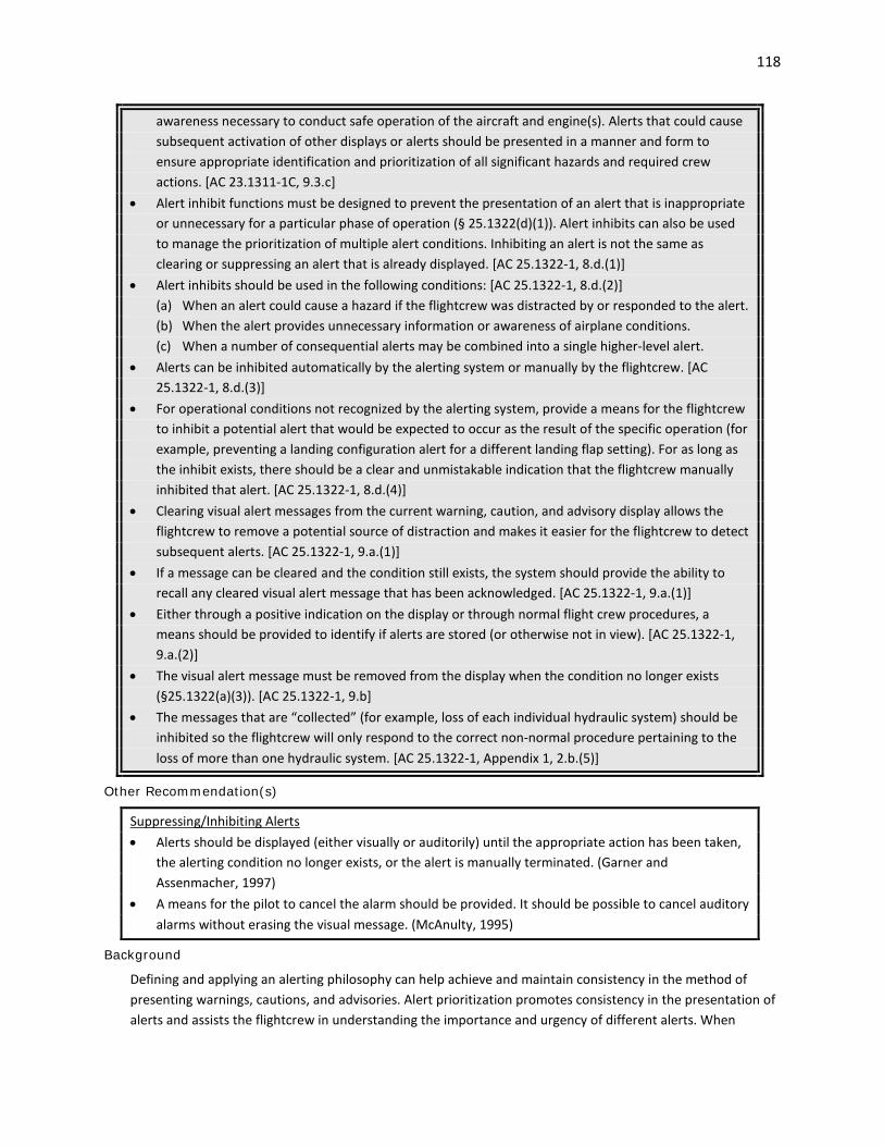
118
awareness necessary to conduct safe operation of the aircraft and engine(s). Alerts that could cause subsequent activation of other displays or alerts should be presented in a manner and form to ensure appropriate identification and prioritization of all significant hazards and required crew actions. [AC 23.1311-1C, 9.3.c]
• Alert inhibit functions must be designed to prevent the presentation of an alert that is inappropriate or unnecessary for a particular phase of operation (§ 25.1322(d)(1)). Alert inhibits can also be used to manage the prioritization of multiple alert conditions. Inhibiting an alert is not the same as clearing or suppressing an alert that is already displayed. [AC 25.1322-1, 8.d.(1)]
• Alert inhibits should be used in the following conditions: [AC 25.1322-1, 8.d.(2)] (a) When an alert could cause a hazard if the flightcrew was distracted by or responded to the alert. (b) When the alert provides unnecessary information or awareness of airplane conditions. (c) When a number of consequential alerts may be combined into a single higher-level alert. • Alerts can be inhibited automatically by the alerting system or manually by the flightcrew. [AC
25.1322-1, 8.d.(3)] • For operational conditions not recognized by the alerting system, provide a means for the flightcrew
to inhibit a potential alert that would be expected to occur as the result of the specific operation (for example, preventing a landing configuration alert for a different landing flap setting). For as long as the inhibit exists, there should be a clear and unmistakable indication that the flightcrew manually inhibited that alert. [AC 25.1322-1, 8.d.(4)]
• Clearing visual alert messages from the current warning, caution, and advisory display allows the flightcrew to remove a potential source of distraction and makes it easier for the flightcrew to detect subsequent alerts. [AC 25.1322-1, 9.a.(1)]
• If a message can be cleared and the condition still exists, the system should provide the ability to recall any cleared visual alert message that has been acknowledged. [AC 25.1322-1, 9.a.(1)]
• Either through a positive indication on the display or through normal flight crew procedures, a means should be provided to identify if alerts are stored (or otherwise not in view). [AC 25.1322-1, 9.a.(2)]
• The visual alert message must be removed from the display when the condition no longer exists (§25.1322(a)(3)). [AC 25.1322-1, 9.b]
• The messages that are “collected” (for example, loss of each individual hydraulic system) should be inhibited so the flightcrew will only respond to the correct non-normal procedure pertaining to the loss of more than one hydraulic system. [AC 25.1322-1, Appendix 1, 2.b.(5)]
Other Recommendation(s)
Suppressing/Inhibiting Alerts • Alerts should be displayed (either visually or auditorily) until the appropriate action has been taken,
the alerting condition no longer exists, or the alert is manually terminated. (Garner and Assenmacher, 1997)
• A means for the pilot to cancel the alarm should be provided. It should be possible to cancel auditory alarms without erasing the visual message. (McAnulty, 1995)
Background
Defining and applying an alerting philosophy can help achieve and maintain consistency in the method of presenting warnings, cautions, and advisories. Alert prioritization promotes consistency in the presentation of alerts and assists the flightcrew in understanding the importance and urgency of different alerts. When

119
prioritizing alerts, consideration should be given to the speed of the response required, the urgency of the response, the number of other cues, and the potential consequences of the failure. While it may be necessary to interrupt the pilot and flightcrew from other ongoing tasks to present urgent information, inhibiting alerts helps to minimize distraction to the flightcrew from what may be perceived as nuisance alerts. For example, routine information may be stored and presented at an appropriate time so as not to disrupt the flightcrew in performing other critical tasks (Cardosi and Huntley, 1993; Cardosi and Murphy, 1995; Palmer, et al., 1995).
Example(s)
Alerts may be prioritized in one of two ways. One way is to categorize alerts by criticality, e.g., in terms of warnings, cautions, and advisories. Another way is to order the alerts them in terms of importance so that when alerts are presented simultaneously, the more urgent alert is given precedence and it suppresses less urgent alerts. Approximately 8 – 11 seconds may be needed for a pilot to respond to a warning message. It is estimated that 2 - 3 seconds may be necessary to allow the pilot to process a visual or auditory warning message, 5 - 6 seconds may be needed to determine the appropriate response, and 1 - 2 seconds to execute the response (Cardosi and Huntley, 1993; Veitengruber, 1979).
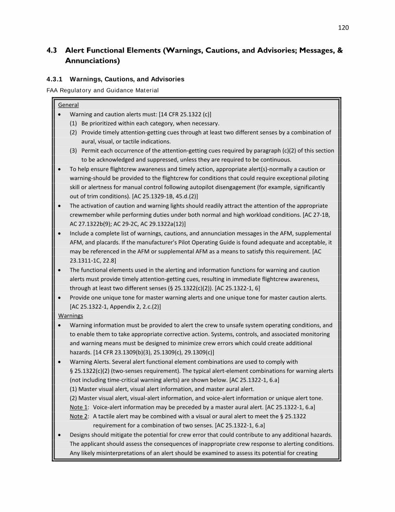
120
4.3 Alert Functional Elements (Warnings, Cautions, and Advisories; Messages, & Annunciations)
4.3.1 Warnings, Cautions, and Advisories
FAA Regulatory and Guidance Material
General • Warning and caution alerts must: [14 CFR 25.1322 (c)] (1) Be prioritized within each category, when necessary. (2) Provide timely attention-getting cues through at least two different senses by a combination of
aural, visual, or tactile indications. (3) Permit each occurrence of the attention-getting cues required by paragraph (c)(2) of this section
to be acknowledged and suppressed, unless they are required to be continuous. • To help ensure flightcrew awareness and timely action, appropriate alert(s)-normally a caution or
warning-should be provided to the flightcrew for conditions that could require exceptional piloting skill or alertness for manual control following autopilot disengagement (for example, significantly out of trim conditions). [AC 25.1329-1B, 45.d.(2)]
• The activation of caution and warning lights should readily attract the attention of the appropriate crewmember while performing duties under both normal and high workload conditions. [AC 27-1B, AC 27.1322b(9); AC 29-2C, AC 29.1322a(12)]
• Include a complete list of warnings, cautions, and annunciation messages in the AFM, supplemental AFM, and placards. If the manufacturer's Pilot Operating Guide is found adequate and acceptable, it may be referenced in the AFM or supplemental AFM as a means to satisfy this requirement. [AC 23.1311-1C, 22.8]
• The functional elements used in the alerting and information functions for warning and caution alerts must provide timely attention-getting cues, resulting in immediate flightcrew awareness, through at least two different senses (§ 25.1322(c)(2)). [AC 25.1322-1, 6]
• Provide one unique tone for master warning alerts and one unique tone for master caution alerts. [AC 25.1322-1, Appendix 2, 2.c.(2)]
Warnings • Warning information must be provided to alert the crew to unsafe system operating conditions, and
to enable them to take appropriate corrective action. Systems, controls, and associated monitoring and warning means must be designed to minimize crew errors which could create additional hazards. [14 CFR 23.1309(b)(3), 25.1309(c), 29.1309(c)]
• Warning Alerts. Several alert functional element combinations are used to comply with § 25.1322(c)(2) (two-senses requirement). The typical alert-element combinations for warning alerts (not including time-critical warning alerts) are shown below. [AC 25.1322-1, 6.a]
(1) Master visual alert, visual alert information, and master aural alert. (2) Master visual alert, visual-alert information, and voice-alert information or unique alert tone. Note 1: Voice-alert information may be preceded by a master aural alert. [AC 25.1322-1, 6.a] Note 2: A tactile alert may be combined with a visual or aural alert to meet the § 25.1322
requirement for a combination of two senses. [AC 25.1322-1, 6.a] • Designs should mitigate the potential for crew error that could contribute to any additional hazards.
The applicant should assess the consequences of inappropriate crew response to alerting conditions. Any likely misinterpretations of an alert should be examined to assess its potential for creating

121
additional hazards. Evaluations should also include an assessment of the adequacy of the feedback given to the crew should they make an inappropriate response to a failure. Qualitative evaluations should also be used to supplement and verify analyses of pilot responses. These evaluations should include sufficient testing using a representative population of pilots to ensure acceptable interpretation of responses. [PS-ACE100-2001-004, Appendix A]
• It is important to provide a warning, caution or alert signal that cannot be confused with either other cockpit visual or auditory displays, or both. It is also important that it aids the crew in determining the root cause of the problem and assists them in taking the appropriate corrective action. In addition, there must be immediate and effective feedback of the result(s) of that action. If an audio alert is used, the pilot must be able to discriminate it from all other audio signals. If multiple similar tones are used in the cockpit, it can complicate the pilot’s task and increase workload. Thus, it is important that auditory alerts be used judiciously. [PS-ACE100-2001-004, Appendix A]
• A threat should trigger an automatic pop-up and the appropriate display on the ND, as well as the appropriate aural alert. Subsequent alerts of a higher priority may override the visual display, but the active aural alert should finish before another aural alert of equal or less urgency begins. [AC 23.1311-1C, 18.5]
• Other functions, such as checklists, synoptic and expanded systems information, should only be shown when selected by the crew or displayed by phase of flight. [AC 23.1311-1C, 18.5]
• Master Visual and Aural Alerts. A master visual alert and a master aural alert may not be warranted if other visual and aural means provide more timely attention-getting characteristics. If a master visual alert and/or a master aural alert are used, they should aid in the overall attention-getting characteristics and the desired flightcrew response and not distract the flightcrew from the time-critical condition. [AC 25.1322-1, 6.c]
Time-Critical Warnings • Some warnings may be so time-critical for the safe operation of the airplane that general alerts such
as a master visual alert and a master aural alert may not provide the flightcrew with immediate awareness of the specific alerting condition that is commensurate with the level of urgency of flightcrew response necessary. In such cases, warning elements dedicated to specific alerting conditions should be provided that give the flightcrew immediate awareness without further reference to other flight deck indications. Examples of such time-critical warnings include reactive windshear and ground proximity. [AC 25.1322-1, 6.b]:
• The alerting elements for time-critical warnings should include: [AC 25.1322-1, 6.b] - Unique voice information or unique tone, or both, for each alerting condition, and - Unique visual alert information in each pilot’s primary field of view for each alerting condition. Note: A unique tactile alert sensed by each pilot can also meet the § 25.1322(c)(2) requirement for
one of the two senses. [AC 25.1322-1, 6.b] • Unique tones associated with time-critical warnings and cautions should be repeated and non-
cancelable until the alerting condition no longer exists (for example, stall warning), unless it interferes with the flightcrew’s ability to respond to the alerting condition. [AC 25.1322-1, Appendix 2, 2.d.(5)]
• Time-Critical Warning Visual Information. The corresponding visual and aural alert information should be consistent. [AC 25.1322-1, Appendix 1, 3.b.(1)]

122
• Time-critical warning visual information may be presented as a text message (for example, “WINDSHEAR”). Certain time-critical warning information, including guidance, may be presented graphically (for example, graphics representing an ACAS II Resolution Advisory). [AC 25.1322-1, Appendix 1, 3.b.(2)]
• If the alert is time-critical and shares a dedicated display region it must have the highest alerting priority to satisfy its intended function (§ 25.1301(a)). [AC 25.1322-1, 8.c.(2)]
See also: Chapter 8 Intended Function • Text messages and graphics for time-critical warning information must be red (§ 25.1322(e)(1)(i)).
When displaying time-critical warnings on monochromatic displays, other graphic coding means must be used (§ 25.1322(e)). [AC 25.1322-1, Appendix 1, 3.b.(3)]
• The information must be removed when corrective actions (e.g. sink rate has been arrested, airplane climbed above terrain, etc.) have been taken, and the alerting condition no longer exists (§ 25.1322(a)(3). [AC 25.1322-1, Appendix 1, 3.b.(4)]
• To immediately attract the attention of the flightcrew and to modify their habit pattern for responding to warnings that are not time-critical, we recommend that a display for time-critical warnings subtend at least 2 square degrees of visual angle. [AC 25.1322-1, Appendix 1, 3.c]
Master Visual Alerts, Annunciations, and Indications • Following the guidance in paragraphs 5 and 6 of AC 25.1322-1, determine whether or not the added
system features will require activation of an airplane master visual alert. [AC 25.1322-1, 14.b] • Unique visual alert information presented in each pilot’s primary field of view is acceptable in place
of a master visual alert if it provides immediate awareness and sufficient attention-getting characteristics. However, an aural alert, such as an aural command to “pull up,” or another sensory cue, would still be required to meet § 25.1322(c)(2). [AC 25.1322-1, 6.c]
• The onset of a master visual alert should occur: [AC 25.1322-1, Appendix 1, 1.b.(1)] (a) In a timeframe appropriate for the alerting condition and the desired response. (b) Simultaneously with the onset of its related master aural alert or unique tone, and its related
visual alert information. Any delays between the onset of the master visual alert and its related master aural alert or unique tone, and its visual alert information should not cause flight crew distraction or confusion.
(c) Simultaneously at each pilot’s station (warnings, cautions). See also: Boucek, Veitengruber, and Smith, 1977 • The master visual alert should remain on until it is cancelled either manually by the flightcrew, or
automatically when the alerting condition no longer exists. [AC 25.1322-1, Appendix 1, 1.b.(2)] • After the master visual alert is cancelled the alerting mechanisms should automatically reset to
annunciate any subsequent fault condition. [AC 25.1322-1, Appendix 1, 1.b.(3)] • In addition to color, steady state or flashing master visual alerts may be used, as long as the method
employed provides positive attention-getting characteristics. If flashing is used, all master visual alerts should be synchronized to avoid any unnecessary distraction. [AC 25.1322-1, Appendix 1, 1.c]
• Master visual alerts should be bright enough to attract the attention of the flightcrew in all ambient light conditions. [AC 25.1322-1, Appendix 1, 1.d.(1)]
• Manual dimming should not be provided unless the minimum setting retains adequate attention-getting qualities when flying under all ambient light conditions. [AC 25.1322-1, Appendix 1, 1.d.(2)] See also: Chapter 2.1 Visual Display Characteristics

123
• Design all character types, sizes, fonts, and display backgrounds so that the alerts are legible and understandable at each pilot’s station. These elements should provide suitable attention-getting characteristics. [AC 25.1322-1, Appendix 1, 1.e.(1)]
• We recommend that the alerts subtend at least 1 degree of visual angle. [AC 25.1322-1, Appendix 1, 1.e.(2)]
• Master visual alerts for conditions other than warnings or cautions (for example, Air Traffic Control (ATC) Datalink alerts) must meet the requirements in § 25.1322(f) and follow the guidance in AC 25.1322-1. We recommend using a color other than red, amber, or yellow. [AC 25.1322-1, Appendix 1, 1.f.(2)]
Master Auditory Alerts, Annunciations, and Indications • The aural alerting must be audible to the flight crew in the worst-case (ambient noise) flight
conditions whether or not the flightcrew are wearing headsets (taking into account their noise attenuation and noise canceling characteristics) (§ 25.1322(a)(2)). The aural alerting should not be so loud and intrusive that it interferes with the flightcrew taking the required action. [AC 25.1322-1, Appendix 2, 2.b.(1)]
• The minimum volume achievable by any adjustment (manual or automatic) should be adequate to ensure it can be heard by the flightcrew if the level of flight deck noise subsequently increases. [AC 25.1322-1, Appendix 2, 2.b.(2)]
• We recommend automatic volume control to maintain an acceptable signal-to-noise ratio. [AC 25.1322-1, Appendix 2, 2.b.(3)]
• To minimize masking, use frequencies different from those that dominate the ambient background noise. [AC 25.1322-1, Appendix 2, 2.a.(3)]
• We do not recommend a master aural alert for advisories because immediate flightcrew attention is not needed for an advisory alert. [AC 25.1322-1, Appendix 2, 2.c.(3)]
• We recommend ramping the onset and offset of any aural alert or unique tone to avoid startling the flightcrew. [AC 25.1322-1, Appendix 2, 2.d.(2)]
(a) A duration for onsets and offsets of 20-30 milliseconds is acceptable. (b) An onset level of 20-30 decibels above the ambient noise level is acceptable. • Use frequencies between 200 and 4500 Hertz for aural signals. [AC 25.1322-1, Appendix 2, 2.a.(1)] • Each sound should differ from other sounds in more than one dimension (frequency, modulation,
sequence, intensity) so that each one is easily distinguishable from the others. [AC 25.1322-1, Appendix 2, 1.b]
• Aural signals composed of at least two different frequencies, or aural signals composed of only one frequency that contains different characteristics (spacing), are acceptable. [AC 25.1322-1, Appendix 2, 2.a.(2)]
• Signal duration of the master aural alert and unique tones should vary, depending on the alert urgency level and the type of response desired. [AC 25.1322-1, Appendix 2, 2.d.(4)]
• Limit the number of different master aural alerts and unique tones, based on the ability of the flightcrew to readily obtain information from each alert and tone. While different studies have resulted in different answers, in general these studies conclude that the number of unique tones should be less than 10. [AC 25.1322-1, Appendix 2, 2.c.(1)]
• The onset of the master aural alert or unique tone should occur in a timeframe appropriate for the alerting condition and the desired response. Any delays between the onset of the master aural alert or unique tone and its related visual alert should not cause flightcrew distraction or confusion. [AC 25.1322-1, Appendix 2, 2.d.(1)]
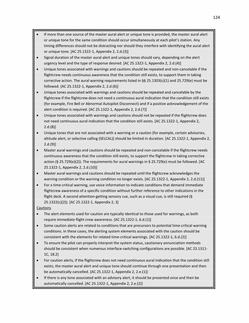
124
• If more than one source of the master aural alert or unique tone is provided, the master aural alert or unique tone for the same condition should occur simultaneously at each pilot’s station. Any timing differences should not be distracting nor should they interfere with identifying the aural alert or unique tone. [AC 25.1322-1, Appendix 2, 2.d.(3)]
• Signal duration of the master aural alert and unique tones should vary, depending on the alert urgency level and the type of response desired. [AC 25.1322-1, Appendix 2, 2.d.(4)]
• Unique tones associated with warnings and cautions should be repeated and non-cancelable if the flightcrew needs continuous awareness that the condition still exists, to support them in taking corrective action. The aural warning requirements listed in §§ 25.1303(c)(1) and 25.729(e) must be followed. [AC 25.1322-1, Appendix 2, 2.d.(6)]
• Unique tones associated with warnings and cautions should be repeated and cancelable by the flightcrew if the flightcrew does not need a continuous aural indication that the condition still exists (for example, Fire Bell or Abnormal Autopilot Disconnect) and if a positive acknowledgement of the alert condition is required. [AC 25.1322-1, Appendix 2, 2.d.(7)]
• Unique tones associated with warnings and cautions should not be repeated if the flightcrew does not need continuous aural indication that the condition still exists. [AC 25.1322-1, Appendix 2, 2.d.(8)]
• Unique tones that are not associated with a warning or a caution (for example, certain advisories, altitude alert, or selective calling (SELCAL)) should be limited in duration. [AC 25.1322-1, Appendix 2, 2.d.(9)]
• Master aural warnings and cautions should be repeated and non-cancelable if the flightcrew needs continuous awareness that the condition still exists, to support the flightcrew in taking corrective action (§ 25.729(e)(2)). The requirements for aural warnings in § 25.729(e) must be followed. [AC 25.1322-1, Appendix 2, 2.d.(10)]
• Master aural warnings and cautions should be repeated until the flightcrew acknowledges the warning condition or the warning condition no longer exists. [AC 25.1322-1, Appendix 2, 2.d.(11)]
• For a time-critical warning, use voice information to indicate conditions that demand immediate flightcrew awareness of a specific condition without further reference to other indications in the flight deck. A second attention-getting sensory cue, such as a visual cue, is still required (§ 25.1322(c)(2)). [AC 25.1322-1, Appendix 2, 3]
Cautions • The alert elements used for caution are typically identical to those used for warnings, as both
require immediate flight crew awareness. [AC 25.1322-1, 6.d.(1)] • Some caution alerts are related to conditions that are precursors to potential time-critical warning
conditions. In these cases, the alerting system elements associated with the caution should be consistent with the elements for related time-critical warnings. [AC 25.1322-1, 6.d.(2)]
• To ensure the pilot can properly interpret the system status, cautionary annunciation methods should be consistent when numerous interface-switching configurations are possible. [AC 23.1311-1C, 18.2]
• For caution alerts, if the flightcrew does not need continuous aural indication that the condition still exists, the master aural alert and unique tone should continue through one presentation and then be automatically cancelled. [AC 25.1322-1, Appendix 2, 2.e.(1)]
• If there is any tone associated with an advisory alert, it should be presented once and then be automatically cancelled. [AC 25.1322-1, Appendix 2, 2.e.(2)]

125
• Provide a means to reactivate canceled aural alerts (for example, the aural alert associated with a gear override). [AC 25.1322-1, Appendix 2, 2.e.(3)]
• When silenced, the aural alerts should be automatically re-armed. However, if there is a clear and unmistakable annunciation in the pilot’s forward field of view that the aural alerts have been silenced, manual re-arming is acceptable. [AC 25.1322-1, Appendix 2, 2.e.(4)]
Advisories • Functional elements used for advisory alerts do not require immediate flightcrew awareness and are
normally provided through a single sense. [AC 25.1322-1, 6] • The alerting and informing functional elements for advisories must meet the applicable
requirements of § 25.1322 and should include visual information. Advisory information should be located in an area where the flightcrew is expected to periodically scan for information. [AC 25.1322-1, 6.e.(1)]
• Advisory information does not require immediate flightcrew awareness. Therefore, it does not require alerting that uses a combination of two senses. In addition, a master visual or master aural alert is not typically used since immediate flightcrew awareness is not needed. [AC 25.1322-1, 6.e.(2)]
• Aural or visual information such as maintenance messages, information messages, and other status messages associated with conditions that do not require an alert may be presented to the flightcrew, but the presentation of this information should not interfere with the alerting function or its use. [AC 25.1322-1, 6.e.(3)] We do not recommend a master aural alert for advisories because immediate flightcrew attention is not needed for an advisory alert. [AC 25.1322-1, Appendix 2, 2.c.(3)]
Other Recommendation(s)
• The auditory signal should be unique to the operating situation to distinguish between warnings, cautions, and advisories. (MIL-STD-1472G; Garner and Assenmacher, 1997; Smith and Mosier, 1986)
Background
Alerts are intended to attract attention and inform of specific airplane operating conditions and events that require pilot and/or flightcrew awareness. As the number of systems on the flight deck has increased, so too has the number of warnings, cautions, and advisories that can be shown. Failure to standardize alerts within the flight deck and across an aircraft fleet can lead to confusion and recognition errors. Different alerting characteristics can prevent the flightcrew from reacting quickly to an alert situation because they are not confident of what the alert is indicating and what action is required. Additionally, it can be more difficult to determine which system generated an alert if alert messages are not easy to interpret.
Defining and applying an alerting philosophy can help achieve and maintain consistency in the method of presenting warnings, cautions, and advisories. Alert prioritization promotes consistency in the presentation of alerts and assists the flightcrew in understanding the importance and urgency of different alerts. Distinguishing noncritical alerts from critical alerts or inhibiting noncritical alerts during high workload phases of flight can prevent the presentation of alerts that distract the flightcrew from more important responsibilities. When prioritizing alerts, consideration should be given to the speed of the response required, the urgency of the response, the number of other cues, and the potential consequences of the failure. While it may be necessary to interrupt the pilot and flightcrew from other ongoing tasks to present urgent information, inhibiting alerts helps to minimize distraction to the flightcrew from what may be perceived as nuisance alerts. For example, routine information may be stored and presented at an appropriate time so as

126
not to disrupt the flightcrew in performing other critical tasks (Cardosi and Huntley, 1993; Cardosi and Murphy, 1995; Palmer, et al., 1995).
Example(s)
TSO-C151c, Terrain Awareness and Warning System (TAWS), provides an alert prioritization scheme for Class A TAWS equipment, as excerpted below in Table 4.3.1.
Table 4.3.1. Alert prioritization. [TSO-C151c, Table 4-2]
Alert Prioritization Scheme Priority Description Level Comments
1 Reactive Windshear Warning W
2 Sink Rate Pull-Up Warning W Continuous
3 Excessive Closure Pull-Up Warning W Continuous
4 RTC Terrain Warning W
5 V1 Callout I
6 Engine Fail Callout W
7 FLTA Pull-Up warning W Continuous
8 PWS Warning W
9 RTC Terrain Caution C Continuous
10 Minimums I
11 FLTA Caution C 7 s period
12 Too Low Terrain C
13 PDA ("Too Low Terrain") Caution C
14 Altitude Callouts I
15 Too Low Gear C
16 Too Low Flaps C
17 Sink Rate C
18 Don't Sink C
19 “ Glideslope” or “Glidepath” C 3 s period
20 PWS Caution C
21 Approaching Minimums I
22 Bank Angle C
23 Reactive Windshear Caution C
Mode 6 TCAS RA ("Climb", "Descend", etc.) W Continuous
Mode 6 TCAS TA ("Traffic, Traffic") C Continuous
Note 1: These alerts can occur simultaneously with TAWS voice callout alerts. Note 2: W = Warning, C = Caution, I = Non Alert Information

127
4.3.2 Messages
FAA Regulatory and Guidance Material
General • Aural or visual information such as maintenance messages, information messages, and other status
messages associated with conditions that do not require an alert may be presented to the flightcrew, but the presentation of this information should not interfere with the alerting function or its use. [AC 25.1322-1, 6.e(3)]
• All current messages shall be retrievable. [TSO-C146c/RTCA DO-229D, 2.2.1.1.5.2] • For any given message, the entire text should fit within the available space of a single page. This
encourages short and concise messages. Additional lines may be used provided the alert message is understandable. [AC 25.1322-1, Appendix 1, 2.b.(3)]
See also: McAnulty, 1995 Message Prioritization • Messages should be prioritized and the message prioritization scheme evaluated and documented.
[AC 120-76B, 12.k] See also: Chandra, et al., 2003, 2.4.8 • Messages should be grouped by urgency level and listed chronologically within each group. [TSO-
C146c/RTCA DO-229D, 2.2.1.1.5.2] See also: RTCA DO-256, 2.1.7.1 which is worded slightly differently. • Within levels of urgency, messages should be displayed in logical order. [AC 25-11A, 31.f.(3)(a)] • When messages are currently being displayed and there are additional messages in the queue that
are not currently displayed, there should be an indication that the additional messages exist. [AC 25-11A, 31.f.(3)(a)]
• An indication shall be provided to identify new messages. The equipment should also indicate when there are current messages. [TSO-C146c/RTCA DO-229D, 2.2.1.1.5.2]
Message Display and Formatting • A text change by itself should not be used as an attention-getting cue (for example, to annunciate
mode changes). [AC 25-11A, 31.f.(3)(b)] • The equipment should provide an indication when additional information (e.g., pages) is available.
[TSO-C146c/RTCA DO-229D, 2.2.1.1.4.1]
Other Recommendation(s)
General • Messages from multiple systems should be integrated so that the same information is conveyed. • New messages should be distinguished from previous messages. • Use short simple sentences. (Smith and Mosier, 1986) • Use affirmative statements rather than negative statements. (Smith and Mosier, 1986) • When a message describes a sequence of events or steps, the same sequence should be followed in
the wording of the message. (Smith and Mosier, 1986) Message Prioritization • A new message should not automatically cover and displace a message currently being displayed.
[RTCA DO-256, 2.1.7.1]

128
Message Queue • The message queue display should indicate the number of pending messages. [RTCA DO-256,
2.1.7.1] • If all pending messages are not displayed, information shall be provided to notify the pilot of the
existence of a queue of these messages. [RTCA DO-256, 2.1.7.1] Message Display and Formatting • Message data shall be available in a directly usable form. If altitude is required in meters or feet,
then both values should be available without requiring the pilot to convert displayed data. [N8110-98]
• Lines of text shall be broken only at spaces or other natural delimiters. [RTCA DO-256, 2.1.7.2] • If the complete message cannot be presented on the same page, there shall be an indicator to the
pilot that the message continues. [RTCA DO-256, 2.1.7.2] • The message display should present all message text and parameters in a uniform size, font, and
style (bold, italics, color) and without emphasis coding of individual data fields upon initial display, to allow flight crew processing and interpretation of the full message content. [RTCA DO-256, 2.1.7.2]
• If multiple displays are available on the flight deck, consistent formats should be used to present messages on all displays. [RTCA DO-256, 2.1.7.2]
Message Composition and Response • If messages require data entry, the system shall provide a preview of all messages as they are
composed, and before they are sent by the pilot. [RTCA DO-256, 2.1.7.3] • The system shall support editing of pilot-composed messages to include entry and correction of
parameter values in pilot-initiated messages. [RTCA DO-256, 2.1.7.3] • For messages that require a pilot response, the system shall indicate the set of appropriate response
options, based upon response attribute. [RTCA DO-256, 2.1.7.3] • For messages that require a pilot response, the system shall label the set of appropriate response
options, e.g., WILCO, UNABLE, STANDBY. [RTCA DO-256, 2.1.7.3] Message Status • An indication shall be provided to identify new messages. The equipment should also indicate when
there are current messages. [TSO-C146c/RTCA DO-229D, 2.2.1.1.5.2] • A positive indication shall be presented to depict error and failed message statuses. [RTCA DO-256,
2.1.7.4] • The system shall maintain and clearly display message status information to the pilot, including but
not limited to whether the message is pending, accepted, or rejected. [RTCA DO-256, 2.1.7.4] Message History • The system shall provide a message history log capability to store, recall, and display messages that
were received and sent. [RTCA DO-256, 2.1.7.5] • Displayed history messages shall be distinguishable from pending and open messages. [RTCA DO-
256, 2.1.7.5] • Message age shall be based on the time that the message was sent. [RTCA DO-256, 2.1.7.5] • History log data shall be clearly marked by means of visual coding to prevent the crew from
interpreting it as new information. [RTCA DO-256, 2.1.7.5] Voice/Speech Messages • To maintain the effectiveness of voice alerting, the use of voice information as an alert element
should be limited. (McAnulty, 1995)
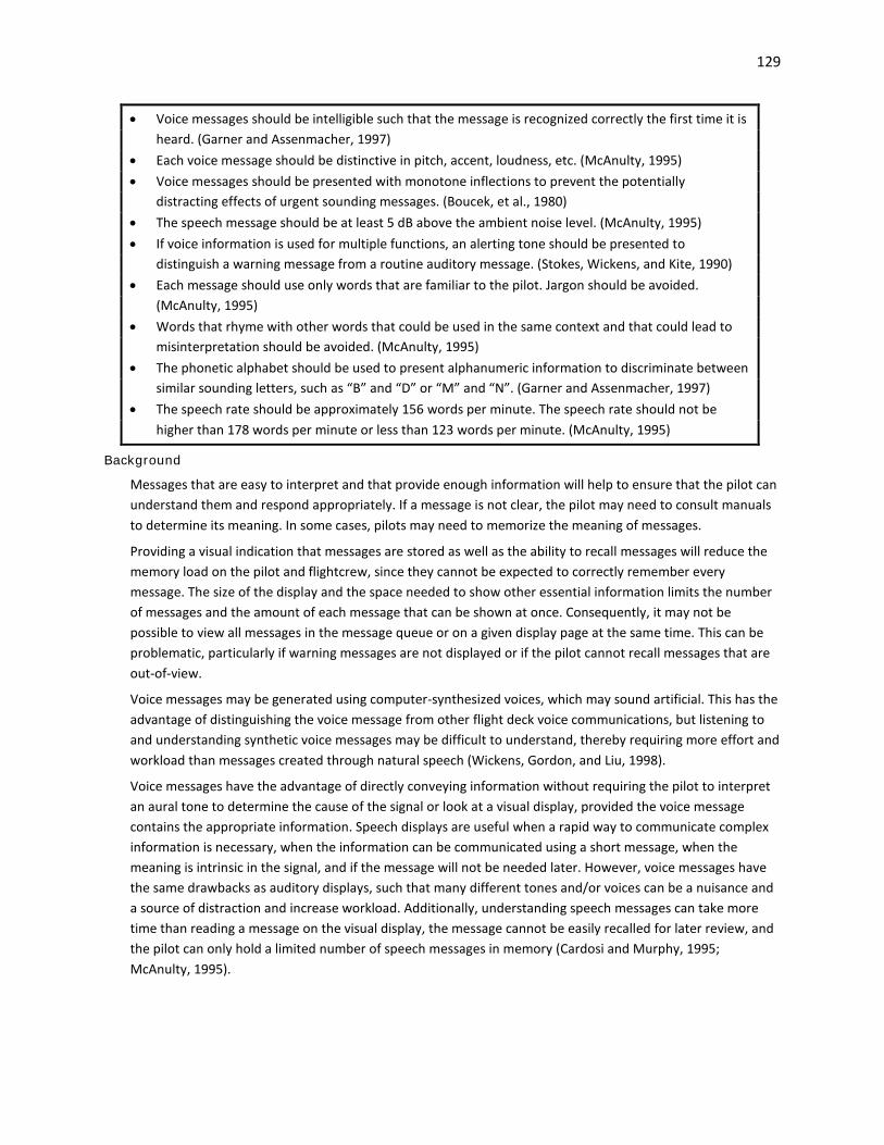
129
• Voice messages should be intelligible such that the message is recognized correctly the first time it is heard. (Garner and Assenmacher, 1997)
• Each voice message should be distinctive in pitch, accent, loudness, etc. (McAnulty, 1995) • Voice messages should be presented with monotone inflections to prevent the potentially
distracting effects of urgent sounding messages. (Boucek, et al., 1980) • The speech message should be at least 5 dB above the ambient noise level. (McAnulty, 1995) • If voice information is used for multiple functions, an alerting tone should be presented to
distinguish a warning message from a routine auditory message. (Stokes, Wickens, and Kite, 1990) • Each message should use only words that are familiar to the pilot. Jargon should be avoided.
(McAnulty, 1995) • Words that rhyme with other words that could be used in the same context and that could lead to
misinterpretation should be avoided. (McAnulty, 1995) • The phonetic alphabet should be used to present alphanumeric information to discriminate between
similar sounding letters, such as “B” and “D” or “M” and “N”. (Garner and Assenmacher, 1997) • The speech rate should be approximately 156 words per minute. The speech rate should not be
higher than 178 words per minute or less than 123 words per minute. (McAnulty, 1995)
Background
Messages that are easy to interpret and that provide enough information will help to ensure that the pilot can understand them and respond appropriately. If a message is not clear, the pilot may need to consult manuals to determine its meaning. In some cases, pilots may need to memorize the meaning of messages.
Providing a visual indication that messages are stored as well as the ability to recall messages will reduce the memory load on the pilot and flightcrew, since they cannot be expected to correctly remember every message. The size of the display and the space needed to show other essential information limits the number of messages and the amount of each message that can be shown at once. Consequently, it may not be possible to view all messages in the message queue or on a given display page at the same time. This can be problematic, particularly if warning messages are not displayed or if the pilot cannot recall messages that are out-of-view.
Voice messages may be generated using computer-synthesized voices, which may sound artificial. This has the advantage of distinguishing the voice message from other flight deck voice communications, but listening to and understanding synthetic voice messages may be difficult to understand, thereby requiring more effort and workload than messages created through natural speech (Wickens, Gordon, and Liu, 1998).
Voice messages have the advantage of directly conveying information without requiring the pilot to interpret an aural tone to determine the cause of the signal or look at a visual display, provided the voice message contains the appropriate information. Speech displays are useful when a rapid way to communicate complex information is necessary, when the information can be communicated using a short message, when the meaning is intrinsic in the signal, and if the message will not be needed later. However, voice messages have the same drawbacks as auditory displays, such that many different tones and/or voices can be a nuisance and a source of distraction and increase workload. Additionally, understanding speech messages can take more time than reading a message on the visual display, the message cannot be easily recalled for later review, and the pilot can only hold a limited number of speech messages in memory (Cardosi and Murphy, 1995; McAnulty, 1995).

130
Example(s)
To make a voice message distinctive, the designer may consider different voices for each message or category of information, vary the speech rate, or precede the message with a distinctive auditory signal (Cardosi and Murphy, 1995; McAnulty, 1995; Smith and Mosier, 1986). However, there are human processing limitations as to number of signals that can be discriminated.

131
4.3.3 Annunciations
FAA Regulatory and Guidance Material
General • Using the display selection control position as annunciation is acceptable only under certain
conditions. For the flight director, it is acceptable if the control position is appropriately labeled to indicate the function. The control position should be in directview of the pilot and it should be obvious under all lighting conditions. [AC 23.1311-1C, 18.1]
Multiple System Configurations • Where multiple system configurations and more than one sensor input are available for source
selection, the switching configuration by annunciation or by selector switch position should be readily visible, readable, and should not be misleading to the pilot using the system. Labels for mode and source selection annunciators should be compatible throughout the cockpit. [AC 23.1311-1C, 18.2]
Mode Annunciations • When an annunciation is provided for the status or mode of a system, it is recommended that the
annunciation indicate the actual state of the system and not just the position or selection of a switch. [AC 25-11A, 31.f.(1)(b)]
• The flight guidance system functions, controls, indications, and alerts must be designed to minimize flightcrew errors and confusion concerning the behavior and operation of the flight guidance system. Means must be provided to indicate the current mode of operation, including any armed modes, transitions, and reversions. Selector switch position is not an acceptable means of indication. The controls and indications must be grouped and presented in a logical and consistent manner. The indications must be visible to each pilot under all expected lighting conditions. [14 CFR 25.1329(i)] See also: 14 CFR 23.1329(h), 27.1329(f), 29.1329(f) which are worded slightly differently.
• Mode changes that are operationally relevant—especially mode reversions and sustained speed protection—should be clearly and positively annunciated to ensure flightcrew awareness. [AC 25.1329-1B, 44.d.(1)]
• The transition from an armed mode to an engaged mode should provide an additional attention–getting feature, such as boxing and flashing on an electronic display (see AC 25-11∗) for a suitable, but brief, period (for example, ten seconds) to assist in flightcrew awareness. Aural notification of mode changes should be limited to special considerations. [AC 25.1329-1B, 44.d.(2)]
• In-service experience has shown that mode annunciation alone may be insufficient-unclear or not compelling enough-to communicate mode changes to the flightcrew, especially in high workload situations. Therefore, the safety consequences of the flightcrew not recognizing mode changes should be considered. If necessary, an appropriate alert should be used. [AC 25.1329-1B, 44.d.(3)]
• Mode information provided to the flightcrew should be sufficiently detailed, so that the consequences of the interaction between the FGS and the flightcrew can be determined unambiguously. The FGS interface should provide timely and positive indication when the FGS deviates from the pilot's direct commands (for example, a target altitude or speed setting) or from the pilot's pre-programmed set of commands (for example, waypoint crossing). The interface should also provide clear indication when there is a difference or conflict between pilot-initiated
∗ Note the source text references AC 25-11, however that AC has been revised; the latest version is AC 25-11A.

132
commands. An example would be when a pilot engages positive vertical speed and then selects an altitude that is lower than the aircraft altitude. The default action taken by the FGS should be made apparent. [AC 25.1329-1B, 44.d.(4)]
• If information from more than one navigation source can be presented, the selected source should be continuously indicated to the pilot. If multiple sources can be presented simultaneously, the display should indicate unambiguously what information is provided by each source and which one has been selected for guidance. Some airplanes are equipped with an autopilot and/or FD coupled to the lateral and vertical guidance system. On these airplanes, the input to the autopilot and/or FD should coincide with the navigation source selected on the PFD or primary navigational display. [AC 23.1311-1C, 10.2(b)]
• The following design considerations are applicable to operationally relevant system behavior and to the modes of operation of the systems: [AC 25.1302-1, 5-6.c.(3)(b)]
1 The design should be simple. 2 Mode annunciation should be clear and unambiguous. As an example, a mode engagement or
arming selection by the flightcrew should result in annunciation, indication, or display feedback adequate to make the flightcrew aware of the effects of their action. Additionally, any change in the mode as a result of the aircraft’s changing from one operational mode (for instance, on an approach) to another should be clearly and unambiguously annunciated and fed back to the flightcrew.
3 Methods of mode arming, engagement and de-selection should be accessible and usable. For example, the flightcrew actions necessary to arm, engage, disarm, or disengage an autopilot mode should not be dependent on the mode the system is in. Requiring a different flightcrew action for each mode could contribute to errors. For specific guidance on flight guidance system modes, see AC 25.1329-1B, Approval of Flight Guidance Systems.
4 Uncommanded mode changes and reversions should have sufficient annunciation, indication, or display information to provide awareness of uncommanded changes of the engaged or armed mode of a system (§ 25.1302(b)(3)).
5 The current mode should remain identified and displayed at all times. See also: AMC 25.1302, 5.5.3 which is worded slightly differently.
Other Recommendation(s)
Mode Annunciations • If the system has the ability to operate in different modes (e.g., maintenance mode), that system
shall continuously indicate what operating mode the system is in. [RTCA DO-256, 2.1.5] • The system logon interface shall indicate the type and format of input data expected, including an
indication of whether the data fields are mandatory or optional. [RTCA DO-256, 2.1.5] • Mode selection or indication of mode annunciations should be clear and unambiguous to prevent
mode confusion. (Ahlstrom and Longo, 2003; Palmer, et al., 1995) See also: Chapter 11 Automation
Background
The recent update of 14 CFR 25.1329 and the associated advisory circular are the result of numerous reports of systems, in particular autopilots, that changed modes without sufficient indication to the flightcrew. Although in many cases, an annunciator light was presented to indicate the current mode, the indication was not always salient given the other ongoing tasks and activities. Since a mode change may cause differences

133
between the flightcrew’s expectations of how the aircraft will behave and how it actually behaves, failure to call attention to these changes may create a safety hazard because the flightcrew could continue to operate as if the change had not occurred. Automatic mode changes (i.e., those that are not the result of flightcrew action but may be the result of pre-programmed instructions or exceeding critical flight parameters) are especially likely to go unnoticed (FAA, 1996; Mitman, Neumeier, Reynolds, and Rehmann, 1994). (See also: Chapter 11 Automation.)
One common mode awareness issue on GPS Nav/Com (GPS/Navigation/Communication) avionics is distinguishing the mode which drives the depiction of the primary course deviation indicator (CDI). In one mode (identified by the display as “GPS” mode), the CDI determines position information from RNAV/GPS satellite navigation data; this mode is indicated by the text “GPS”. In the other mode (identified as “VOR” or “VLOC”), the CDI determines position information from the entered VOR, localizer, or glideslope. The mode change is subtle (a change from “VOR” or “VLOC” to “GPS”) and may not be noticed by pilots. It is important to ensure modes are properly annunciated and easy to understand.
Example(s)
The flight mode annunciator of the primary flight display (PFD) is located in the pilot’s primary field-of-view. The mode annunciator is divided into columns or sections; Boeing aircraft generally show three columns, and Airbus aircraft show five. The information shown includes autothrust/autothrottle modes, lateral modes, and vertical modes. Additional autopilot status information is shown below the flight mode annunciator or in additional columns. The top row indicates the current mode engaged. A box is drawn around the mode status for 10 seconds after engagement. Under the current mode indication, there is an indication of the armed mode or mode that the automation will switch to next based on flight programming.
Some airlines have adopted procedures for improving monitoring, particularly for autoflight systems. One procedure is described by the acronym CAMI:
Confirm airborne (or ground) inputs to the FMS with the other pilot.
Activate the input
Monitor mode annunciations to ensure the autoflight system performs as desired, and
Intervene if necessary.
Reference: Commercial Aviation Safety Team, 2008; Summwalt, Thomas, and Dismukes, 2002; ASRS Callback Issue 379, http://asrs.arc.nasa.gov/publications/callback/cb_379.html)

134
4.4 Alerting System Reliability and Integrity
FAA Regulatory and Guidance Material
General • The alerting system, considered alone and in relation to other systems, should meet the safety
objectives of the relevant system safety standards (for example, § 25.901(b)(2), § 25.901(c), and § 25.1309(b)). The reliability and integrity of the alerting system should be commensurate with the safety objectives associated with the system function, or airplane function, for which the alert is provided. [AC 25.1322-1, 7.a]
• Since the flightcrew-alerting function is often integrated with, or is common to, other systems, the impact of a failure or error in the alerting system must be assessed separately and in relation to other systems as required by § 25.1309(b). The cascading effects of a failure or error in the alerting function, and in the interfacing system, should be analyzed. Give special consideration to avoid alerting that, through misinterpretation, could increase the hazard to the airplane (§ 25.1309(c)). [AC 25.1322-1, 7.c]
• When applying the § 25.1309(b) system safety analysis process to a particular system or function that has an associated flightcrew alert, assess both the failure of the system or function and a failure of its associated alert (§ 25.1309(d)(4)). This should include assessing the effect of a single (common or cascading mode) failure that could cause the failure of a system function and the failure of any associated alerting function. A failure is defined as: “An occurrence that affects the operation of a component, part, or element such that it can no longer function as intended. This includes both loss of function and malfunction.” Therefore, in conducting the safety analysis, both loss of functions and malfunctions should be considered. [AC 25.1322-1, 7.b]
• Assess the reliability of the alerting system by evaluating the reduction in the safety margin if the alerting system fails. The evaluation should address: [AC 25.1322-1, 7.d]
(1) Loss of the complete alerting function. (2) A malfunction. (3) Loss or malfunction of one alert in combination with the system condition for which the alert is
necessary. False/Nuisance Alerts • The integrity of the alerting system should be examined because it affects the flightcrew’s trust and
response when assessing an alert. Since the individual assessment of a false or nuisance alert for a given system may lead to a specific consequence, the impact of frequent false or nuisance alerts increases the flightcrew’s workload, reduces the flightcrew’s confidence in the alerting system, and affects their reaction in case of a real alert. For example, if false or nuisance alerts are presented the flightcrew may ignore a real alert when it is presented. [AC 25.1322-1, 7.e]
• The alert function must be designed to minimize the effects of false and nuisance alerts. In particular, it must be designed to: [14 CFR 25.1322 (d)]
(1) Prevent the presentation of an alert that is inappropriate or unnecessary. (2) Provide a means to suppress an attention-getting component of an alert caused by a failure of
the alerting function that interferes with the flightcrew's ability to safely operate the airplane. This means must not be readily available to the flightcrew so that it could be operated inadvertently or by habitual reflexive action. When an alert is suppressed, there must be a clear and unmistakable annunciation to the flightcrew that the alert has been suppressed.
See also: AC 25.1322-1 is worded slightly differently.

135
• As much as possible, the alerting functions or system should be designed to avoid false alerts and nuisance alerts, while providing reliable alerts to the flightcrew when needed. [AC 25.1322-1, 12]
• Pulling circuit breakers is not an acceptable primary means for the flightcrew to suppress a false alert. [AC 25.1322-1, 12.e]
• Care should be taken to set appropriate thresholds for these alerts so that they are not considered a nuisance for the flightcrew. [AC 25.1329-1B, 45.d.(2)]
Failure Identification • If a visual indicator is provided to indicate malfunction of an instrument, it must be effective under
all probable cockpit lighting conditions. [14 CFR 23.1321(e), 25.1321(e), 27.1321(d), 29.1321(g)] • The same colors used for displaying flightcrew alerts are used for displaying failure flags. In the
integrated environment of the flight deck it is appropriate to display instrument failure flags in a color consistent with the alerting system, as part of the alerting function. [AC 25.1322-1, Appendix 1, 4]
• Failure warning or indication may either be natural (inherent) or designed into a system. In either case, it should be timely, rousing, obvious, clear, and unambiguous. It should occur at a point in a potentially catastrophic sequence of failures where the airplane's capability and the crew's ability still remain sufficient for appropriate corrective crew action. [AC 25.1309-1A, 8.g.(1)]
• Even if operation or performance is unaffected or insignificantly affected at the time of failure, warning is required if it is considered necessary for the crew to take any action or observe any precautions. Warning is also required if a failure must be corrected before a subsequent flight. [AC 25.1309-1A, 8.g.(3)]
• When a failure occurs or when using reversionary modes, an annunciation of abnormal system status must be provided, in accordance with § 23.1311(a)(7). The display is not to provide misleading information. [AC 23.1311-1C, 18.1]
• When the display receives a “data not valid” or “reduced performance” (e.g., dead reckoning mode) indication from the source, this condition shall be indicated on the display within one second. [TSO-C165/RTCA DO-257A, 2.2.4]
Notes: [TSO-C165/RTCA DO-257A, 2.2.4] 1. For vertical profile displays, if the altitude source fails or is degraded, the altitude data must
be flagged or removed from the display. 2. Caution- some Global Navigation Satellite System (GNSS) receivers compliant with TSO-
C129a do not provide this indication via the data bus. These position sources may continue to output last known position after a sensor failure. This is not acceptable.
Loss of Signal/Function • If aircraft positioning data are not received by the display for five seconds (i.e., data timeout), this
condition shall be indicated to the flight crew. [TSO-C165/RTCA DO-257A, 2.2.4] • If there is an active flight plan and the flight plan data are not received by the display for 30 seconds,
this condition shall be indicated to the flight crew. [TSO-C165/RTCA DO-257A, 2.2.4] Notes: [TSO-C165/RTCA DO-257A, 2.2.4]
1. This minimum is based on the use of the map display for position awareness only. It is recommended that the time-out for the active flight plan data be less than 30 seconds if the interface characteristics support this.

136
2. Surface moving maps are not required to have flight plan information while on the airport surface. This requirement does apply to surface moving maps that have flight plan information and also to surface moving maps that depict a taxi route. Otherwise, this requirement does not apply to surface moving maps.
• The loss of navigation caution shall be output/displayed within one second of the onset of any of the following conditions: [TSO-C146c/RTCA DO-229D, 2.2.2.6.3]
a. The absence of power (loss of function is an acceptable indicator); b. Equipment malfunction or failure; c. The presence of a condition lasting five seconds or more where there are an inadequate number
of satellites to compute a position solution; d. Fault detection detects a position failure that cannot be excluded within the time-to-alert when
integrity is provided by fault detection and exclusion (FDE). Note: Once a failure is detected relative to the horizontal protection level (HPLFD), the horizontal
uncertainty level (HUL) may be used to bound the error until it exceeds the horizontal alert limit (HAL). This provides the most time for the exclusion algorithm to exclude the failure without increasing the probability of a missed alert. [TSO-C146c/RTCA DO-229D, 2.2.2.6.3]
• The fault detection function shall detect positioning failures within the following times-to-alert. A detection results in a loss of navigation caution. [TSO-C146c/RTCA DO-229D, 2.2.2.6.3]
Time-to-Alert Oceanic/Remote 1 minute En Route: 30 seconds Terminal: 10 seconds • The equipment shall distinguish between these different causes of the loss of navigation capability.
For example, a single loss of navigation caution can be provided, if it is accompanied by a message for conditions b) through d) indicating the cause of the alert. A blank display could indicate condition a). [TSO-C146c/RTCA DO-229D, 2.2.2.6.3]
• The caution shall be returned to its normal state immediately upon termination of the responsible condition. [TSO-C146c/RTCA DO-229D, 2.2.2.6.3]
Note: A loss of navigation alert does not require removal of navigation information from the navigation display. Consideration should be given to continued display of navigation information concurrent with the failure/status annunciation when conditions warrant. [TSO-C146c/RTCA DO-229D, 2.2.2.6.3]
Other Recommendation(s)
Failure Identification • Means shall be provided to indicate malfunctions or failures to the appropriate crew member. A
blank display or a “X” across the display are examples of acceptable means of indicating failure. [SAE AS8034B, 3.8.1]
• Loss of ownship position, if depicted, should be indicated clearly and immediately. • Means shall be provided to indicate when electrical power (voltage and/or current of all required
phases), is not sufficient for proper operation of display and/or display system. A blank display is an example of acceptable means of indicating failure. [SAE AS8034B, 3.8.2]

137
• An alert should be provided when: (Palmer, et al., 1995) - An automated function approaches its protection limits, or - When the automation encounters a failure and cannot perform reliably and accurately.
See also: Chapter 5.3 Reversionary Displays, Display Reconfiguration, and Managing Display Failure; Chapter 11 Automation
• Failure annunciations should be provided with enough time for the pilot to adjust to the new control demands.
See also: Chapter 5.3 Reversionary Displays, Display Reconfiguration, and Managing Display Failure; Chapter 11 Automation
Background
Alerts are distracting by nature. The same display characteristics that attract attention also divert it from other ongoing tasks. This is particularly a problem with auditory alerts, which may interfere with communications on the flight deck and prevent the pilot from dealing with other tasks or other visual or auditory signals. False and nuisance alerts are especially distracting. A high number of false alerts (i.e., the presentation of an alert when it is not needed) or alerts that provide inaccurate instructions may lead pilots to distrust the system and in the future, respond slower to real and high-urgency alerts. In extreme cases, pilots may simply suppress an alert before they determine whether a hazardous condition exists (Allendoerfer, Friedman-Berg, and Pai, 2007; Cardosi and Huntley, 1993; Parasuraman and Riley, 1997; Wickens and Dixon, 2005).
Example(s)
There are several ways of helping pilots assess the reliability of an alert. One way is to clearly indicate the system settings so that the pilot can ensure that the system is performing according to expectations. A second way is to present the raw data so that the pilot can understand why the alert condition exists. In this case, it may also be important to indicate what data is missing or uncertain so that the pilot understands what information may be unreliable. A third method is to indicate the likelihood that an alerting condition exists, e.g., the graded alert levels in TCAS (Tsang and Vidulich, 2003).

138
4.5 Alert Integration
FAA Regulatory and Guidance Material
Interface or Integration with Other Systems (Checklist and Synoptics) • The color of all visual alerting annunciations and indications must conform to the color convention in
§ 25.1322(e). Use consistent wording, position, color and other shared attributes(for example, graphic coding) for all alerting annunciations and indications. [AC 25.1322-1, 10.b]
See also: Chapter 4.1 Considerations for Alerting: General • Information displayed in the flight deck associated with the alert condition must facilitate the
flightcrew’s ability to identify the alert (§ 25.1322(a)(1)(i)) and determine the appropriate actions, if any (§ 25.1322(1)(ii)). [AC 25.1322-1, 10.b]
• Information conveyed by the alerting system should lead the flightcrew to the correct checklist procedure to facilitate the appropriate flightcrew action. In all cases, the airplane- or system-certification test program should verify that the alerts provide or direct the flightcrew to the correct procedures. [AC 25.1322-1, 10.c]
• If multiple checklists can be displayed (for example, multiple checklists associated with multiple alerts), the flightcrew should be able to readily and easily choose the appropriate checklist and action for each alert. For example, the flightcrew must be able to easily distinguish which checklist has priority regarding what the flightcrew needs to do first to determine the appropriate actions, if any (§ 25.1322(a)(1)(ii)). [AC 25.1322-1, 10.d]
Retrofits • System upgrades to existing airplanes should be compatible with the original airplane’s flightcrew-
alerting philosophy. The existing alerting system might not be able to facilitate the integration of additional systems and associated alerts due to limitations in the system inputs, incompatible technologies between the airplane and the system being added, or economic considerations. [AC 25.1322-1, 14. a.(2)]
(a) We discourage incorporating a new additional master visual function into the flightcrew-alerting system. If it is not feasible to include additional systems and associated alerts in the existing master visual function, an additional master visual function may be installed, provided that it does not delay the flightcrew’s response time for recognizing and responding to an alert.
(b) Where possible, new alerts should be integrated into the existing flightcrew alerting system. If these alerts cannot be integrated, individual annunciators or an additional alerting display system may be added.
(c) Not all alerts associated with failure flags need to be integrated into the central alerting system. However, for those alerts requiring immediate flightcrew awareness, the alert needs to meet the attention-getting requirements of § 25.1322(c)(2) as well as the other requirements in § 25.1322. Thus, a master visual or master aural alert may not be initiated, but an attention-getting aural or tactile indication must still accompany an attention-getting visual failure flag to meet the attention-getting requirement of § 25.1322(a)(1), which requires attention-getting cues through at least two different senses for warning and caution alerts.
• Following the guidance in paragraphs 5 and 6 of AC 25.1322-1, determine whether or not the added system features will require activation of an airplane master visual alert. [AC 25.1322-1, 14.b]
• Using the guidance in AC 25.1322-1, determine if an added system will require activating an aural alert. [AC 25.1322-1, 14.c.(1)]

139
• The new aural alert should be integrated into the existing aural alerting system and functions. If this is not possible, a separate aural alerting system may be installed, provided that a prioritization scheme between existing aural alerts and the new aural alerts is developed so that each alert is recognized and can be acted upon in the time frame appropriate for the alerting situation. This may require a demonstration of any likely combination of simultaneous alerts. After the new and existing alerts have been merged, follow the guidance in this AC for determining how to prioritize the alerts. [AC 25.1322-1, 14.c.(2)]
• Using the guidance in this AC, determine if an added system will require activating a tactile alert. [AC 25.1322-1, 14.d.(1)]
• If possible, incorporate the new tactile alert into the existing aural alerting system. If this is not possible, a separate tactile alerting system may be installed, provided that the following elements are included: [AC 25.1322-1, 14.d.(2)]
(a) A prioritization scheme between existing tactile alerts and the new tactile alerts should be developed so that each alert is recognized and can be acted upon in the time frame appropriate for the alerting situation. After the new and existing alerts have been merged, follow the guidance in this AC for determining how to prioritize the alerts.
(b) A means to ensure that an individual alert can be understood and acted upon. This may require a demonstration of any likely combination of simultaneous alerts.
Background
Flight deck alerting technology has evolved from the use of discrete lights to logic-based integrated and prioritized visual, aural, and tactile flightcrew alerts. “Smart alerting” systems monitor the aircraft’s status and operating environment to provide timely alerts when needed. These alerting systems may be retrofitted in existing airplanes if the original technology has the capacity to accept additional inputs to the system and if the technologies are compatible.
The number of alerting systems for the flight deck continues to increase, but a concern is the lack of integration among these systems. These alerting systems may be independent units that are developed by different avionics manufacturers, each of which may use a different alerting or display philosophy to provide information to the flightcrew.
The Engine Indicating and Crew Alert System (EICAS) display integrates warning, caution, advisory, and status messages in one location. EICAS provides more specific information to notify the flightcrew as to the nature of the problem/error than a visual or auditory signal and displays those messages in the same color scheme as specified for warning, caution, and advisory lights, with respect to the priority of the message. EICAS also provides status information on different aircraft systems (e.g., engine, electrical system, fuel, etc.). Status information for different systems is presented on the left side of the display and the right side is dedicated for flightcrew alerting.
Example(s)
For one aircraft EICAS system, warning messages are displayed in red, located at the top of the display, and accompanied by the onset of the master warning light and an aural tone. Caution messages are displayed in amber and presented in conjunction with a master warning light and a series of tones. Advisory messages are located to the right of warning and caution messages and are not accompanied by any other visual or auditory signals.
A second solution is the “Alerting and Notification of Conditions Outside the Aircraft” concept, which is intended to integrate the alerts related to conditions outside the aircraft (e.g., terrain, traffic, and weather).

140
As part of the concept, alerts were integrated onto the master caution and warning annunciation panel and messages were incorporated onto the navigation display. See Ververs and Dorneich (2003) for more information (http://www.imse.iastate.edu/dorneich/files/2013/02/2002-06-21_HFES02_ANCOA.pdf).

141
4.6 Demonstrating Compliance for Alerts
FAA Regulatory and Guidance Material
• Documentation should include the results of analyses and tests that show that any delayed or inhibited alerts do not adversely impact safety. [AC 25.1322-1, 8.a.(5)]
• When following the guidance in AC 25.1322-1, document any divergence, and provide the rationale for decisions regarding novel or unusual features used in the design of the alerting system. This will facilitate the certification evaluation because it will enable the FAA to focus on areas where the proposed system diverges from the AC and has new or novel features. [AC 25.1322-1, 13.b]
• Demonstrations and tests intended to show compliance should use production quality hardware and be conducted in a variety of lighting conditions (for example, dark, bright forward field, shafting sunlight). Due to the effect other aircraft electrical systems have on individual systems, compliance tests should be conducted in the airplane, although supporting data from laboratory testing may be submitted to supplement airplane testing. [PS-ACE100-2001-004, Appendix A]
• We recommend developing a plan to establish how compliance with the rules will be shown and to document how issues will be identified, tracked, and resolved throughout the life cycle of the certification program. We also recommend including the FAA early in the developmental process to discuss the acceptability of any proposed flight-deck-design-and-alerting philosophy and the conditions that should be alerted to the flightcrew. Typically, a certification plan is used for this purpose. [AC 25.1322-1, 13.a]
• In accordance with the certification plan, provide an evaluation of the alerting system. In this case an evaluation is an assessment of the alerting system conducted by an applicant, who then provides a report of the results to the FAA. Evaluations are different from tests because the representation of the alerting system does not necessarily conform to the final documentation and the FAA may or may not be present. Evaluations by the applicant may contribute to a finding of compliance, but they do not constitute a complete showing of compliance by themselves. [AC 25.1322-1, 13.c]
(1) The evaluation should include assessments of acceptable performance of the intended functions, including the human-machine interface, and acceptability of alerting system failure scenarios. The scenarios should reflect the expected operational use of the system. Specific aspects that should be included during the evaluation(s) are:
(a) Visual, aural, and tactile/haptic aspects of the alert(s). (b) Effectiveness of meeting intended function from the human/machine integration, including
workload, the potential for flightcrew errors, and confusion. (c) Normal and emergency inhibition-and-suppression logic and accessibility of related
controls. (d) Proper integration with other systems, including labeling. This may require testing each
particular alert and verifying that the appropriate procedures are provided. (e) Acceptability of operation during failure modes per § 25.1309. (f) Compatibility with other displays and controls, including multiple warnings. (g) Ensuring that the alerting system by itself does not issue nuisance alerts or interfere with
other systems. (h) Inhibiting alerts for specific phases of flight (for example, takeoff and landing) and for
specific airplane configurations (for example, abnormal flaps and gear). (2) The validation of the performance and integrity aspects will typically be accomplished by a
combination of the following methods: - Analysis

142
- Laboratory test - Simulation - Flight test (3) Evaluate the alerts in isolation and combination throughout the appropriate phases of flight and
maneuvers, as well as representative environmental and operational conditions. The alerting function as a whole needs to be evaluated in a representative flight deck environment. Representative simulators can be used to accomplish the evaluation of some human factors and workload studies. The level and fidelity of the simulator should be commensurate with the certification credit being sought. The simulator should represent the flight deck configuration and be validated by the FAA. The assessment of the alerts may be conducted in a laboratory, simulator, or the actual airplane. Certain elements of the alerting system may have to be validated in the actual airplane. The evaluation should be conducted by a representative population of pilots with various backgrounds and expertise.
(4) Evaluations should also verify the chromaticity (red looks red and amber looks amber) and discriminability (colors can be distinguished from each other) of the colors being used, under the expected lighting levels. Evaluations may also be useful to verify the discriminability of graphic coding used on monochromatic displays. These evaluations can be affected by the specific display technology being used, so a final evaluation with production representative hardware is sometimes needed.
See also: Chapter 8 Intended Function • If possible, incorporate the new tactile alert into the existing aural alerting system. If this is not
possible, a separate tactile alerting system may be installed, provided that the following elements are included: A means to ensure that an individual alert can be understood and acted upon. This may require a demonstration of any likely combination of simultaneous alerts. [AC 25.1322-1, 14.d.(2)(b)]
Background
The appropriate evaluation to demonstrate compliance for a proposed alerting function/system will vary depending on specific system characteristics (e.g., complexity, level of system integration) and the product development stage when the evaluation is conducted. The evaluation may be conducted as part of a laboratory/office test, simulation, or flight test. AC 25.1322-1 provides specific aspects of the alerting system to include as part of the evaluation for part 25 aircraft.
Example(s)
Compliance with this requirement [14 CFR 25.1322] is typically shown by a description of each of the warning, caution, and advisory lights (or their electronic equivalents). Evaluations may also be useful to verify the chromaticity (for example, red looks red, amber looks amber) and discriminability (i.e., colors can be distinguished reliably from each other) of the colors being used, under the expected lighting levels. These evaluations can be affected by the specific display technology being used, so final evaluation with flight quality hardware is sometimes needed. A description of a well-defined color coding philosophy, which is consistently applied across flight deck systems, can be used to show how the design avoids ‘possible confusion’. [PS-ANM100-01-03A, Appendix A, 3]
See also: PS-ACE100-2001-004, Appendix A is worded slightly differently.

143
5 Organizing Electronic Display Information Elements
This chapter provides guidance for organizing displays and managing the information elements on the display. Chapter 5.1 addresses the basic T arrangement. Chapter 5.2 addresses displays that use windows to manage information and show various functions in one area. Chapter 5.3 addresses the effect of system failures, understanding and mitigating their effects, and how information should be rearranged if a display fails. 5.1 Basic “T” Arrangement
FAA Regulatory and Guidance Material
• The following flight and navigation instruments must be installed at each pilot station [14 CFR 25.1303(b)]
(1) An airspeed indicator. If airspeed limitations vary with altitude, the indicator must have a maximum allowable airspeed indicator showing the variation of VMO with altitude.
(2) An altimeter (sensitive). (3) A rate-of-climb indicator (vertical speed). (4) A gyroscopic rate-of-turn indicator combined with an integral slip-skid indicator (turn-and-bank
indicator) except that only a slip-skid indicator is required on large airplanes with a third attitude instrument system usable through flight attitudes of 360° of pitch and roll and installed in accordance with [Sec. 121.305(k)] of this title.
(5) A bank and pitch indicator (gyroscopically stabilized). (6) A direction indicator (gyroscopically stabilized, magnetic or nonmagnetic). See also: 14 CFR 23.1303, 27.1303, and 29.1303 which are worded slightly differently. • The flight instruments required by Sec. 25.1303 must be grouped on the instrument panel and
centered as nearly as practicable about the vertical plane of the pilot's forward vision. In addition: [14 CFR 25.1321(b)]
(1) The instrument that most effectively indicates attitude must be on the panel in the top center position;
(2) The instrument that most effectively indicates airspeed must be adjacent to and directly to the left of the instrument in the top center position;
(3) The instrument that most effectively indicates altitude must be adjacent to and directly to the right of the instrument in the top center position.
(4) The instrument that most effectively indicates direction of flight must be adjacent to and directly below the instrument in the top center position.
See also: 14 CFR 23.1321(d), 29.1321(b) which is worded slightly differently. • The Basic T information should be displayed continuously, directly in front of each flightcrew
member under normal (that is, no display system failure) conditions. [AC 25-11A, 36.b.(3)(b)1] • The attitude indication should be placed so that the display is unobstructed under all flight
conditions. [AC 25-11A, 36.b.(3)(b)3] • The primary airspeed, altitude, and direction of flight indications should be located adjacent to the
primary attitude indication. Information elements placed within, overlaid, or between these indications, such as lateral and vertical deviation, are acceptable when they are relevant to respective airspeed, altitude, or directional indications used for accomplishing the basic flying task,

144
and are shown to not disrupt the normal crosscheck or decrease manual flying performance. [AC 25-11A, 36.b.(3)(b)4]
• The center of the airspeed indication should be aligned with the center of the attitude indication. For airspeed indications, vertical deviations have been found acceptable up to 15 degrees below to 10 degrees above when measured from the direct horizontal position of the airplane waterline reference symbol. For tape type airspeed indications, the center of the indication is defined as the center of the current airspeed status reference. [AC 25-11A, 36.b.(3)(b)5]
• Parameters related to the primary airspeed indication, such as reference speeds or a mach indication, should be displayed to the left of the primary attitude indication. [AC 25-11A, 36.b.(3)(b)6]
• The center of the altitude indication should be aligned with the center of the attitude indication. For altitude indications, vertical deviations have been found acceptable up to 15 degrees below to 10 degrees above when measured from the direct horizontal position of the airplane waterline reference symbol. For tape type altitude indications, the center of the indication is defined as the center of the current altitude status reference. [AC 25-11A, 36.b.(3)(b)7]
• Parameters related to the primary altitude indication, such as the barometric setting or the primary vertical speed indication, should be displayed to the right of the primary altitude indication. [AC 25-11A, 36.b.(3)(b)8]
• The center of the direction of flight indication should be aligned with the center of the attitude indication. The center of the direction of flight indication is defined as the center of the current direction of flight status reference. [AC 25-11A, 36.b.(3)(b)9]
• Parameters related to the primary direction of flight indication, such as the reference (that is, magnetic or true) or the localizer deviation should be displayed below the primary attitude indication. [AC 25-11A, 36.b.(3)(b)10]
• Required engine indications necessary to set and monitor engine thrust or power should be continuously displayed in the flightcrew’s primary field of view, unless the applicant can demonstrate that this is not necessary. The automatically selected display of powerplant information should not suppress other information that requires flightcrew awareness. [AC 25-11A, 36.b.(4)(a)] See also: Chapter 2.3 Field-of-View
• Powerplant information must be closely grouped (in accordance with § 25.1321) in an easily identifiable and logical arrangement which allows the flightcrew to clearly and quickly identify the displayed information and associate it with the corresponding engine. Place parameter indications in order of importance with the most important one at the top. Typically, the top indication is the primary thrust setting parameter. [AC 25-11A, 36.b.(4)(b)] See also: Chapter 3.1 Electronic Display Information Elements and Features: General
• Typically, it is considered to be acceptable to arrange parameters related to one powerplant in a vertical manner and, according to powerplant position, next to the parameters related to another powerplant in such a way that identical powerplant parameters are horizontally aligned. Generally, place parameter indications in order of importance with the most important one at the top. Typically, the top indication is the primary thrust setting parameter. [AC 25-11A, 36.b.(4)(b)]
• Glideslope or glidepath deviation scales should be located to the right side of the primary attitude indication. If glideslope deviation data is presented on both an electronic horizontal situation indicator and an electronic attitude direction indicator, the information should appear in the same relative location on each indicator. [AC 25-11A, 36.b.(5)(a)]

145
• The basic T-configuration should be used for airplanes certificated under § 23.1321, Amendment 23-14, or a later amendment. The basic T-configuration is defined as an arrangement where the airspeed and altitude data are centered, respectively, directly to the left and right of the attitude data, with the direction data located directly below the attitude data. [AC 23.1311-1C, 14.2]
• Deviations from the basic T-configuration have been approved for individual instrument arrangements if the droop angle (angle below the § 23.1321(d) position) is 15 degrees or less, or if the elevated angle is 10 degrees or less. These angles are measured from a horizontal reference line that passes through the center of the attitude reference data with lines passing through the center of the airspeed and altitude data. [AC 23.1311-1C, 14.3.a]
• Unique displays or arrangements for attitude, altitude, airspeed, and navigation data, integration of combinations of these functions, or rearrangement of them from the basic T configuration, may be approved when an equivalent level of safety, and a human factors evaluation are provided. This evaluation should consider the different types of airplane operations, as defined by § 23.1559(b). Coordination with the Small Airplane Directorate is required. Deviations beyond these limits may be approved for individual flight instruments through a human factors evaluation and display installation evaluation, considering the following items: [AC 23.1311-1C, 14.3.b]
(1) The display arrangement and its alignment to the normal line of the pilot's vision; (2) The cockpit view; (3) The integration of other functions within the displays; (4) The data presented, format, symbology, etc., within the display; and (5) The ease of manipulating controls associated with the displays. • The primary flight instrument basic T (or a modified T with VSI above the altimeter) should be
located directly in front of the pilot. All annunciation necessary for operation of stability systems should be readily in view. Secondary flight (or navigation) instruments such as radar altimeter and secondary radio course information, DME, etc., should be grouped around the periphery of the T. Next in priority are primary power instruments such as torque and rotor RPM. Powerplant instruments and backup attitude information should be placed in the remaining panel areas. [AC 27-1B, AC 27 Appendix B, b.(8)(i); AC 29-2C, AC 29 Appendix B, b.(8)(i)]
• The standby attitude indicator must be usable and flyable from the primary pilot station (and any other pilot station); however, locating it too close to the primary instruments may be undesirable and should be evaluated. [AC 27-1B, AC 27 Appendix B, b.(8)(i); AC 29-2C, AC 29 Appendix B, b.(8)(i)]
Background
Most aircraft built since the mid 1950’s have four important flight instruments located in a standard “T” arrangement often called the basic “T”. This basic arrangement consists of the artificial horizon or attitude indicator (AI) occupying the top center position; the airspeed indicator located to the left of the AI; the altimeter to the right of the AI; and, the heading indicator or directional gyro under the AI. This configuration was the result of research on flight instrument panel arrangements conducted in the 1930s by the British Royal Air Force (RAF) for military aircraft. The RAF’s goal for this research was to standardize the flight deck panel arrangements across all their aircraft to facilitate pilots’ transition from one aircraft to another (Williamson, 1937).
Example(s)
Modern glass cockpit aircraft incorporates this basic T arrangement on a glass display. The AI is in the central position, a partial compass image is displayed below the AI, a moving airspeed tape and numerical airspeed

146
are located to the left of the AI, and the altimeter tape, numerical altitude and vertical speed representations are to the right of the AI. This pattern is similar to the basic “T” arrangement in “round gauge” cockpits.

147
5.2 Managing Display Information
FAA Regulatory and Guidance Material
General • Navigation, weather, and vertical situation display information is often displayed on multi-function
displays. When this information is not required to be displayed continuously, it can be displayed part-time, but the displayed information should be easily recoverable to the flightcrew when needed. [AC 25-11A, 36.b.(5)(c)]
Windows • The window(s) should have fixed size(s) and location(s). [AC 25-11A, 36.c.(1)] • Separation between information elements within and across windows should be sufficient to allow
the flightcrew to readily distinguish separate functions or functional groups and avoid any distractions or unintended interaction. [AC 25-11A, 36.c.(1)]
• Display of selectable information, such as a window on a display area, should not interfere with or affect the use of primary flight information. [AC 25-11A, 36.c.(1)]
• For those systems that integrate windowing architecture into the display system, a means should be provided to control the information shown on the displays, such that the integrity of the display system as a whole will not be adversely impacted by anomalies in the functions being integrated. This means of controlling the display of information should be developed to the software assurance level at least as high as the highest integrity function of any window. [AC 25-11A, 21.e.(9)]
See also: Chapter 5.3 Reversionary Displays, Display Reconfiguration, and Managing Display Failure Menus See also: Chapter 6.1 Controls: General that provides considerations for use of menus for multi-function
controls • The hierarchical structure and organization of the menus should be designed to allow the flightcrew
to sequentially step through the available menus or options in a logical way that supports their tasks. [AC 25-11A, 36.c.(2)(b)]
• The options provided on any particular menu should be logically related to each other. [AC 25-11A, 36.c.(2)(b)]
• Menus should be displayed in consistent locations, either a fixed location or a consistent relative location, so that the flightcrew knows where to find them. [AC 25-11A, 36.c.(2)(b)]
• At all times the system should indicate the current position within the menu and menu hierarchy. [AC 25-11A, 36.c.(2)(b)]
• The number of sub-menus should be designed to assure timely access to the desired option without over-reliance on memorization of the menu structure. The presentation of items on the menu should allow clear distinction between items that select other menus and items that are the final selection. [AC 25-11A, 36.c.(2)(c)]
• The number of steps required to choose the desired option should be consistent with the frequency, importance, and urgency of the flightcrew’s task. [AC 25-11A, 36.c.(2)(d)]
• When a menu is displayed it should not obscure required information. [AC 25-11A, 36.c.(2)(e)] • In menus, the layering of information should not hinder the pilot in identifying the location of the
desired control. Location and accessibility are not only related to the physical location of the control function. They also include consideration of where the control functions are located within various menu layers, and how the pilot navigates through those layers to access functions. [AC 20-175, 3-6]
See also: AC 25.1302-1, 5-4.d.(3) which is worded slightly differently.

148
• For menu-based controls, ensure that the number and complexity of steps required to access and utilize a control is appropriate to the intended use of the control (e.g., frequently used controls and emergency controls should be available at top-level menus). The number of sub-menus should be designed to ensure timely access to the desired option without over-reliance on memorization of the menu structure. [AC 20-175, 3-6.a]
• Cockpit controls must be located and identified to provide convenient operation and to prevent confusion, per § 2X.777(a). Layer information on menus or hidden pages so it does not hinder the flightcrew in identifying the location of the desired control. [AC 20-175, 3-6.b] See also: AMC 25.1302, 5.3.4 which is worded slightly differently.
• Fit top-level control menu pages (e.g., primary or “home” page) entirely on the display (i.e., do not require scrolling). [AC 20-175, 3-6.c]
• Make top-level control menus readily accessible. This is typically accomplished by continuously displaying the menu or menu access control in a fixed location (e.g., “home” page). [AC 20-175, 3-6.d]
• Provide feedback from page navigation that is an unambiguous indication of the current location. [AC 20-175, 3-6.e]
Pop-up Information • The display should be designed so that it is very evident that an automatic pop-up has occurred. [AC
27-1B, Chapter 3 AC27 MG 18j(3)(ii)(D); AC 29-2C, Chapter 3 AC 29 MG 18j(3)(ii)(D)] • Pop-up window locations should not obscure required information. [AC 25-11A, 36.c.(3)(b).1] • Consider the following criteria for displaying automatic pop-up information: [AC 25-11A,
36.c.(3)(b).2] - Information is automatically displayed when its value indicates a predetermined condition, or
when the associated parameter reaches a predetermined value. - Pop-up information should appropriately attract the flightcrew’s attention while minimizing task
disruption. - If the flightcrew deselects the display of the automatic pop-up information, then another
automatic pop-up should not occur until a new condition/event causes it. - If an automatic pop-up condition is activated and the system is in the wrong configuration or
mode to display the information, and the system configuration cannot be automatically changed, then an annunciation should be displayed in the color associated with the nature of the alert, prompting the flightcrew to make the necessary changes for the display of the information. This guidance differs from the part-time display of information required by part 25 because the required information should be displayed regardless of the configuration.
- If a pop-up(s) or simultaneous multiple pop-ups occur and obscure information, it should be shown that the obscured information is not relevant or necessary for the current flightcrew task. Additionally, the pop-ups should not cause a misleading presentation.
- If more than one automatic pop-up occurs simultaneously on one display area, for example a terrain and TCAS pop-up, then the system should prioritize the pop-up events based on their criticality. Pop-up display orientation should be in track-up or heading-up.
- Any information to a given system that is not continuously displayed, but the safety assessment determines it is necessary to be presented to the flightcrew, should automatically pop-up or otherwise indicate that its display is required.

149
• If implemented, an automatic pop-up feature should incorporate the following considerations in its design: [AC 27-1B, Chapter 3 AC 27 MG 18j(3)(ii); AC 29-2C, AC 29 MG 18j(3)(ii)]
(A) The pop-up functionality should automatically display Helicopter Terrain Awareness and Warning System (HTAWS)-related information when an HTAWS caution alert occurs.
(B) The terrain and obstacle display mode should be annunciated on the display. If this is not feasible, a mode annunciation light should be installed near the terrain and obstacle display.
(C) The pop-up functionality should be implemented consistently for weather, predictive wind shear, and traffic alerts, including any overlay design philosophies. The pop-up must not impair the pilot’s use of essential flight or navigational information.
(D) The display should be designed so that it is very evident that an automatic pop-up has occurred. (E) Manually switching back to the original mode of operation should require minimal effort. (F) Automatic switching back to the original mode of operation after the caution or warning ceases
should not be allowed unless it is part of the aircraft design philosophy. • For dual displays, pop-up functionality may be inhibited if the terrain and obstacle map is on at least
one display when a terrain alert occurs. However, if the terrain and obstacle map is not on a display when a terrain alert occurs, the terrain and obstacle map, with the alerts, should be automatically displayed on at least one display. [AC 27-1B, Chapter 3 AC 27 MG 18j(3)(iii); AC 29-2C, AC 29 MG 18j(3)(iii)]
Multiple Applications • The system should provide continuous indication of which application and/or document is active if
the system supports multiple open documents, or if the system allows multiple open applications. The active document is the one that is currently displayed and responds to user actions. Under non-emergency, normal operations, the user should be able to select which of the open applications or documents is currently active. In addition, the user should be able to find which open flight deck applications are running and switch to any one of these open applications easily. When the user returns to an application that was running in the background, it should appear in the same state as when the user left that application, other than differences associated with the progress or completion of processing performed in the background. [AC 120-76B, 12.h]
Other Recommendation(s)
General • A style guide should document methods for designing the user interface elements (e.g., windows,
menus, and pop-up information) and standard methods for performing common actions (e.g., opening and closing windows). (Chandra, et al., 2003)
• Lines and borders may be drawn around the group to help identify the information relationships. (Wickens, Gordon, and Liu, 1998)
Windows • Windows should be avoided when the hardware has the following limitations: (Ahlstrom and Longo,
2003) a. small screen size, resulting in frequent manipulation of the screen by the user, b. slow processing speed, resulting in slow operation by the computer, or c. low screen resolution, resulting in less effective visual coding, especially for map graphics,
symbols, and icons. • The flightcrew should be able to open, close, move, resize, and minimize windows. (Cardosi and
Murphy, 1995; Ahlstrom and Longo, 2003)

150
• If several windows are displayed at one time, the system should clearly indicate which window is active. (Smith and Mosier, 1986)
• The size of the window should minimize the amount of scrolling needed. • The method for controlling window overlays should be consistent from one window to another.
(Smith and Mosier, 1986) • When a user can select predefined window overlays, assign to each overlay an identifying label.
(Smith and Mosier, 1986) • The relationship between windows should be clearly indicated. Windows that are independent of
each other should have contrasting features. (Cardosi and Murphy, 1995) Menus • Menu organization should support specific pilot tasks e.g., responding to controller-initiated
messages and composing and sending messages. [RTCA DO-256, 2.1.2.4] • If a menu option is never available to the pilot (e.g., a maintenance function), the option should not
be in the menu displayed to the pilot. [RTCA DO-256, 2.1.2.4] • If a menu option is temporarily unavailable (i.e., it cannot be selected or activated because of the
current system context), it should be displayed in the menu with an indication that it is unavailable. [RTCA DO-256, 2.1.2.4]
• Menu options that are not active or unavailable can be grayed out or dimmed. (Smith and Mosier, 1986)
• When hierarchic menus are used, only one action should be required to return to the next higher level. [RTCA DO-256, 2.1.2.4]
• When hierarchic menus are used, only one action should be required to return to the menu at the top level. [RTCA DO-256, 2.1.2.4]
• The system should not require the pilot to traverse more than three levels in a menu structure, and no more than two levels for frequently performed tasks. [RTCA DO-256, 2.1.2.4]
• Prompts, menu options, and error messages should indicate the action to be executed. [RTCA DO-256, 2.1.2.4]
• The system should clearly indicate which, if any, option on a menu has been selected. (Avery, et al., 1999; Garner and Assenmacher, 1997; Palmer, et al., 1995)
• Menu options provided on more than one menu should be positioned consistently. (Cardosi and Murphy, 1995; Garner and Assenmacher, 1997; Palmer, et al., 1995)
• Menus should display between three to ten options per level. (Avery, et al., 1999; Ahlstrom and Longo, 2003)
• The menu should distinguish between options that lead to actions and choices that lead to submenus. (Avery, et al., 1999; Ahlstrom and Longo, 2003)
• A menu should appear disabled if all its options are not active or not available. (Ahlstrom and Longo, 2003)
• The wording of menu options should be consistent with the resulting system behavior. (Cardosi and Murphy, 1995; Smith and Mosier, 1986)
Background
A window is a defined area on the display, which is dedicated to a specific application or activity. The term “pop-up” can be used to refer either to information that is presented automatically or to information that appears at the pilot’s request. Windows are only one way to organize information, and a display can show multiple windows at once. However, adding additional windows can make it more difficult to integrate
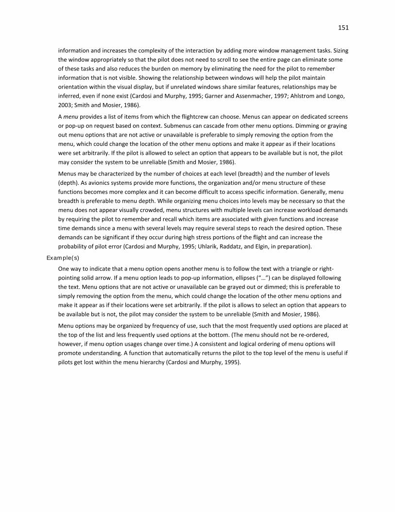
151
information and increases the complexity of the interaction by adding more window management tasks. Sizing the window appropriately so that the pilot does not need to scroll to see the entire page can eliminate some of these tasks and also reduces the burden on memory by eliminating the need for the pilot to remember information that is not visible. Showing the relationship between windows will help the pilot maintain orientation within the visual display, but if unrelated windows share similar features, relationships may be inferred, even if none exist (Cardosi and Murphy, 1995; Garner and Assenmacher, 1997; Ahlstrom and Longo, 2003; Smith and Mosier, 1986).
A menu provides a list of items from which the flightcrew can choose. Menus can appear on dedicated screens or pop-up on request based on context. Submenus can cascade from other menu options. Dimming or graying out menu options that are not active or unavailable is preferable to simply removing the option from the menu, which could change the location of the other menu options and make it appear as if their locations were set arbitrarily. If the pilot is allowed to select an option that appears to be available but is not, the pilot may consider the system to be unreliable (Smith and Mosier, 1986).
Menus may be characterized by the number of choices at each level (breadth) and the number of levels (depth). As avionics systems provide more functions, the organization and/or menu structure of these functions becomes more complex and it can become difficult to access specific information. Generally, menu breadth is preferable to menu depth. While organizing menu choices into levels may be necessary so that the menu does not appear visually crowded, menu structures with multiple levels can increase workload demands by requiring the pilot to remember and recall which items are associated with given functions and increase time demands since a menu with several levels may require several steps to reach the desired option. These demands can be significant if they occur during high stress portions of the flight and can increase the probability of pilot error (Cardosi and Murphy, 1995; Uhlarik, Raddatz, and Elgin, in preparation).
Example(s)
One way to indicate that a menu option opens another menu is to follow the text with a triangle or right-pointing solid arrow. If a menu option leads to pop-up information, ellipses (“…”) can be displayed following the text. Menu options that are not active or unavailable can be grayed out or dimmed; this is preferable to simply removing the option from the menu, which could change the location of the other menu options and make it appear as if their locations were set arbitrarily. If the pilot is allows to select an option that appears to be available but is not, the pilot may consider the system to be unreliable (Smith and Mosier, 1986).
Menu options may be organized by frequency of use, such that the most frequently used options are placed at the top of the list and less frequently used options at the bottom. (The menu should not be re-ordered, however, if menu option usages change over time.) A consistent and logical ordering of menu options will promote understanding. A function that automatically returns the pilot to the top level of the menu is useful if pilots get lost within the menu hierarchy (Cardosi and Murphy, 1995).

152
5.3 Reversionary Displays, Display Reconfiguration, and Managing Display Failure
FAA Regulatory and Guidance Material
General • For systems that operate the instruments required by § 25.1303(b) which are located at each pilot's
station— [14 CFR 25.1333] (a) Means must be provided to connect the required instruments at the first pilot's station to
operating systems which are independent of the operating systems at other flight crew stations, or other equipment;
(b) The equipment, systems, and installations must be designed so that one display of the information essential to the safety of flight which is provided by the instruments, including attitude, direction, airspeed, and altitude will remain available to the pilots, without additional crewmember action, after any single failure or combination of failures that is not shown to be extremely improbable; and
(c) Additional instruments, systems, or equipment may not be connected to the operating systems for the required instruments, unless provisions are made to ensure the continued normal functioning of the required instruments in the event of any malfunction of the additional instruments, systems, or equipment which is not shown to be extremely improbable.
See also: 14 CFR 29.1333 which is worded slightly differently. • Information intended for the flightcrew must be accessible and useable by the flightcrew in a
manner consistent with the urgency, frequency, and duration of their tasks, per § 25.1302(b)(2). The flightcrew may, at certain times, need some information immediately. Other information may not be necessary during all phases of flight. [AC 25.1302-1, 5-5.c.(1)(a)]
See also: AMC 25.1302, 5.4.3.a which is worded slightly differently. • 14 CFR 23.1311(b), Amendment 23-62, states the electronic display indicators, including their
systems and installations, and considering other airplane systems, must be designed so that one display of information essential for continued safe flight and landing will be available within one second to the crew by a single pilot action or by automatic means for continued safe operation, after any single failure or probable combination of failures. To meet the requirements of § 23.1311(b), a full-time standby display, another independent PFD, or an independent reversionary attitude display, must be installed. Reversionary modes could be automatically and manually selected or only manually selected. [AC 23.1311-1C, 8.4.1.a]
Failure Identification • The analysis of the failure condition should identify the impacted functionality, the effect on the
airplane and/or its occupants, any considerations related to phase of flight, and identify any flight deck indication, flightcrew action, or other relevant mitigation means. [AC 25-11A, 21.a]
• When a flight deck design includes primary and standby displays, consider failure conditions involving the failure of standby displays in combination with the failure of primary displays. The flightcrew may use standby instruments in two complementary roles following the failure of primary displays: [AC 25-11A, 21.a.(2)]
(a) Redundant display to cope with failure of main instruments, or (b) Independent third source of information to resolve inconsistencies between primary
instruments. • When the display of erroneous information is caused by failure of other systems which interface
with the display system, the effects of these failures may not be limited to the display system.

153
Associated failure conditions may be dealt with at the airplane level or within the other systems’ safety assessment, as appropriate, in order to assess the cumulative effect. [AC 25-11A, 21.a.(3)]
• There should be a means to detect the loss or erroneous primary flight information, either as a result of a display system failure or the failure of an associated sensor. When loss or malfunction of primary flight information is detected, the means used to indicate the lost or erroneous information should ensure that the erroneous information will not be used by the flightcrew. [AC 25-11A, 21.e.(4)]
• The means used to indicate the lost or erroneous information, when it is detected, should be independent of the failure mechanism. Common mode failures of identical processor types should be considered. [AC 25-11A, 21.e.(5)]
• The latency period induced by the display system, particularly for alerts, should not be excessive and should take into account the criticality of the alert and the required crew response time to minimize propagation of the failure condition. [AC 25-11A, 21.e.(8)]
Failure Mitigation • The electronic display indicators, including their systems and installations, and considering other
airplane systems, must be designed so that one display of information essential for continued safe flight and landing will remain available to the crew, without need for immediate action by any pilot for continued safe operation, after any single failure or probable combination of failures. [14 CFR 23.1311(b)]
• When determining mitigation means for a failure condition consider the following: [AC 25-11A, 21.c.(1)]
- Protection against common mode failures. - Fault isolation and reconfiguration. - Redundancy (for example, heading information may be provided by an independent integrated
standby and/or a magnetic direction indicator). - Availability of, level of, timeliness of, and type of, alert provided to the flightcrew. - The flight phase and the aircraft configuration. - The duration of the condition. - The aircraft motion cues that may be used by the flightcrew for recognition. - Expected flightcrew corrective action on detection of the failure, and/or operational procedures. - In some flight phases, ability of the flightcrew to control the airplane after a loss of primary
attitude display on one side. - The flightcrew’s ability to turn off a display (for example, full bright display at night). - Protections provided by other systems (for example, flight envelope protection or augmentation
systems). • The mitigation means should be described in the safety analysis/assessment document or by
reference to another document (for example, a system description document). The continued performance of the mitigation means, in the presence of the failure conditions, should also be identified and assured. [AC 25-11A, 21.c.(2)]
• The safety assessment should include the rationale and coverage of any display system protection and monitoring philosophies used in the design. The safety assessment should also include an evaluation of each of the identified display system failure conditions and an analysis of the exposure to common mode/cause or cascade failures in accordance with ARAC’s recommendations for revising AC 25.1309-1A. Additionally, the safety assessment should justify and describe any

154
functional partitioning schemes employed to reduce the effect of integrated component failures or functional failures. [AC 25-11A, 21.c.(3)]
Display Reconfiguration • Alternative display locations used in non-normal conditions should be evaluated by the FAA or its
designees to determine if the alternative locations meet the criteria for acceptability. [AC 25-11A, 36.d.(2)]
• Moving display formats to different display locations on the flight deck or using redundant display paths to drive display information is acceptable to meet availability and integrity requirements. [AC 25-11A, 36.d.(2)(a)]
• In an instrument panel configuration with a display unit for primary flight information positioned above a display unit for navigation information, it is acceptable to move the primary flight information to the lower display unit if the upper display unit fails. [AC 25-11A, 36.d.(2)(b)]
• In an instrument panel configuration with a display unit for primary flight information positioned next to a display unit for navigation information, it is acceptable to move the primary flight information to the display unit directly adjacent to it if the preferred display unit fails. It is also acceptable to switch the navigation information to a centrally located auxiliary display (multi-function display). [AC 25-11A, 36.d.(2)(c)]
• If several possibilities exist for relocating the failed display, a recommended flightcrew procedure should be considered and documented in the airplane flight manual. [AC 25-11A, 36.d.(2)(d)]
• It is acceptable to have manual or automatic switching capability (automatic switching is preferred) in case of system failure; however, the ARAC recommendation for revising § 25.1333(b) requires that the equipment, systems, and installations must be designed so that sufficient information is available to assure control of the airplane’s airspeed, altitude, heading, and attitude by one of the pilots without additional flightcrew action, after any single failure or combination of failures that is not assessed to be extremely improbable. [AC 25-11A, 36.d.(2)(e)]
• The following means to reconfigure the displayed information are acceptable: [AC 25-11A, 36.d.(2)(f)]
- Display unit reconfiguration. Moving a display format to a different location (for example, moving the primary flight information to the adjacent display unit) or the use of a compacted format may be acceptable.
- Source/graphic generator reconfiguration. The reconfiguration of graphic generator sources either manually or automatically to accommodate a failure may be acceptable. In the case where both the captain and first officer’s displays are driven by a single graphic generator source, there should be clear, cautionary alerting to the flightcrew that the displayed information is from a single graphic generator source.
• In certain flight phases, manual reconfiguration may not satisfy the need for the pilot controlling the airplane to recover primary flight information without delay. Automatic reconfiguration might be necessary to ensure the timely availability of information that requires immediate flightcrew member action. [AC 25-11A, 36.d.(2)(f)1]
• When automatic reconfiguration occurs (for example, display transfer), it should not adversely affect the performance of the flightcrew and should not result in any trajectory deviation. [AC 25-11A, 36.d.(2)(f)2]
• When the display reconfiguration results in the switching of sources or display paths that is not annunciated and is not obvious to the flightcrew, care should be taken that the flightcrew is aware

155
of the actual status of the systems when necessary, depending on flight deck philosophy. [AC 25-11A, 36.d.(2)(f)3]
• Display of PFI on reversionary or standby displays should be arranged in the basic T-configuration, but it is not required. [AC 23.1311-1C, 8.2]
Compacted Format • The “compacted format” may be automatically selected in case of a primary display failure, or it may
be manually (automatic selection preferred) selected by the flightcrew. Except for training purposes, the “compacted format” should not be selectable unless there is a display failure. [AC 25-11A, 36.e.(1)(a)]
• The compacted display format should maintain the same display attributes (color, symbol location, etc.) and include the same required information, as the primary formats it is replacing. The compacted format should ensure the proper operation of all the display functions it presents, including annunciation of navigation and guidance modes, if present. [AC 25-11A, 36.e.(1)(b)]
• Failure flags and mode annunciations should, wherever possible, be displayed in a location common with the normal format. [AC 25-11A, 36.e.(1)(b)]
• Reversionary display modes should provide consistent display formats to the PFD. The reversionary flight information should be presented by an independent source and display to prevent complete loss of PFI due to a single failure. The reversionary configuration should have two independent displays that incorporate dual-independently powered AHRS and dual ADC subsystems that provide PFIs. The reversionary system response time should provide flight critical information on the MFD in less than one second after a single pilot action or an automatic operation. [AC 23.1311-1C, 8.4.1c]
• A reversionary configuration should have a single pilot action that would force both the PFD and MFD displays into reversionary mode operation. However, the PFI should be presented in similar format and sufficient size in the reversionary mode as it is in normal mode to allow the pilot to enhance the control of the airplane. This reversionary configuration should provide backup information essential to continued safe flight and landing with an intuitive control that allows instant, simultaneous access to reversionary mode on both the PFD and MFD displays. The single pilot action should be easily recognized, readily accessible, and have the control within the pilot’s primary optimum field of view. An acceptable method for the single pilot action is the red color and/or lighted red “halo” ring that announces its position on the panel at all times. [AC 23.1311-1C, 8.4.1d]
• One method is to have an automatic reversionary display with a single pilot action that would force both the PFD and MFD displays into reversionary mode operation. If PFI on another display is not provided, provide automatic switching to ensure PFI is available to the pilot. Automatic reversion must provide a complete display of PFI on the remaining display within one second if a fault is detected. [AC 23.1311-1C, 8.4.2a]
• Most possible faults should be covered by this automatic reversionary capability. Only a total loss of the display may not be reliably detected automatically, but such a failure condition would be obvious to the pilot. Faults that result in automatic switching should be extensive enough to ensure PFI availability meets the requirements of § 23.1309. If such a malfunction occurs, a single pilot action should provide a full display of the essential information on the remaining display within one second. All modes, sources, frequencies, flight plan data, etc., should be similar as they were on the PFD before the failure. [AC 23.1311-1C, 8.4.2b]
• Another reversionary method would include a means to access the reversionary mode manually through a single pilot action. Manual activation of the reversionary mode on the MFD through single

156
action by the pilot is acceptable when procedures to activate the PFI on the MFD are accomplished before entering critical phases of flight. The PFI would be presented continuously on the reversionary display during critical phases of flight (for example, takeoff, landing, and missed or final approach). [AC 23.1311-1C, 8.4.2c]
• Reversionary requirements for navigation display information depend on the rules under which the aircraft is operated and the hazards associated with the loss of or misleading information from the display. The integration of non-navigation information (for example, traffic, weather or flight parameters) may affect the hazards associated with the loss of, or misleading information from, the display. In these cases, the applicant should perform a system safety assessment following AC 23.1309-1E. [AC 23.1311-1C, 10.3]
• Clutter should be a major consideration during the reversionary or compacted modes. When combining essential information on a display after another display or unit fails, the display format should not be confusing and the information should still be usable, including unusual attitude. If clutter is anticipated, provide a means to manually remove the clutter (decluttering). Automatic decluttering, such as during specific phases of flight, or during certain alerts, may also be appropriate. [AC 23.1311-1C, 17.3] See also: Chapter 3.8 Integrated Display Issues
• Each reversionary or standby display providing primary flight information should be powered from a power source independent of the source for the primary display. It should function independently from the power source of the primary display, such as a second alternator or battery. [AC 23.1311-1C, 24.3]
Source/Graphic Generator Reconfiguration • Automatic switching of sensor data to the display system is recommended, especially with highly
integrated display systems to address those cases where multiple failure conditions may occur at the same time and require immediate flightcrew action. Manual switching may be acceptable in less complex systems or if immediate flightcrew action is not required. [AC 25-11A, 36.e.(2)(a)]
• Independent attitude, direction, and air data sources are required for the captain and first officer’s displays of primary flight information (see § 25.1333). If sources can be switched such that the captain and first officer are provided with single sensor information, each of them should receive a clear annunciation indicating the vulnerability to misleading information. [AC 25-11A, 36.e.(2)(b)]
• If sensor information sources cannot be switched, then no annunciation is required. [AC 25-11A, 36.e.(2)(c)]
• There should be a means of determining the source of the displayed navigation information and the active navigation mode. For approach operations the source of the displayed navigation information and the active navigation mode should be available on the primary flight display or immediately adjacent to the primary flight display. [AC 25-11A, 36.e.(2)(d)]
• The selected source should be annunciated if multiple or different types of navigation sources (flight management system, instrument landing system, GNSS (global navigation satellite system) landing system, etc.) can be selected (manually or automatically). [AC 25-11A, 36.e.(2)(e)]
• An alert should be given when the information presented to the flightcrew is no longer meeting the required integrity level, in particular when there is a single sensor or loss of independence. [AC 25-11A, 36.e.(2)(f)]

157
System Safety Guidelines • Any probable failure of the display shall not degrade the normal operation of other equipment or
systems connected to it beyond degradation due to the loss of the display itself. [TSO-C165/RTCA DO-257A, 3.1.4]
• The failure of interfaced equipment or systems shall not degrade normal operation of the display beyond degradation due to the loss of data from the interfaced equipment. [TSO-C165/RTCA DO-257A, 3.1.4]
• When an integrated standby display is used to provide a backup means of primary flight information, the safety analysis should substantiate that common cause failures have been adequately addressed in the design, including the design of software and complex hardware. In particular, the safety analysis should show that the independence between the primary instruments and the integrated standby instruments is not violated because the integrated standby display may interface with a large number of airplane components, including power supplies, pitot static ports, and other sensors. [AC 25-11A, 21.e.(3)]
• A catastrophic failure condition should not result from the failure of a single component, part, or element of a system. Failure containment should be provided by the system design to limit the propagation of the effects of any single failure and preclude catastrophic failure conditions. In addition, there should not be a common cause failure that could affect both the single component, part, or element and its failure containment provisions. [AC 25-11A, 21.e.(6)]
• For safety-critical display parameters, there should be a means to verify the correctness of sensor input data. Range, staleness, and validity checks should be used where possible. [AC 25-11A, 21.e.(7)]
• For those systems that integrate windowing architecture into the display system, a means should be provided to control the information shown on the displays, such that the integrity of the display system as a whole will not be adversely impacted by anomalies in the functions being integrated. This means of controlling the display of information should be developed to the software assurance level at least as high as the highest integrity function of any window. [AC 25-11A, 21.e.(9)]
Demonstrating Compliance • The applicant should show the flightcrew can access and manage (configure) all necessary
information on the dedicated and multifunction displays for the phase of flight. The applicant should show any information required for continued safe flight and landing is accessible in the relevant degraded display modes following failures, as defined by § 25.1309(d)(1), (2), (3), and (4). The applicant must show, per § 25.1302(b), that supplemental information does not displace or otherwise interfere with required information. [AC 25.1302-1, 5-5.c.(1)(a)]
See also: AMC 25.1302, 5.4.3.a which is worded slightly differently.
Other Recommendation(s)
Failure Identification (See also: Chapter 4.4 Alerting System Reliability and Integrity; Chapter 11 Automation) • The automation should be designed so that the user is continuously aware of its status (e.g.,
whether it is functioning or malfunctioning) and the potential consequences of the function (or malfunction). (Billings, 1997)
• An alert should be provided when: (Palmer, et al., 1995) - An automated function approaches its protection limits, or - When the automation encounters a failure and cannot perform reliably and accurately.
158
• Failure annunciations should be provided with enough time for the pilot to adjust to the new control demands.
Background
A reversionary display is “a secondary means to provide information initially presented on the PFD or MFD by the transfer of information to an alternate display” (AC 23.1311-1C, 6.2nn). A compacted format is a “reversionary display mode where selected display components of a multi-display configuration are combined in a single display format to provide higher priority information following a display failure.” [AC 25-11A, 36.e.(1)(a)]
Flight deck displays can be reconfigured when there is a failure so that information necessary for safe flight is still available. The method for reconfiguration may vary; information can be moved to a different location or shown using a “compacted format” or the source/graphic generator may be switched so that the captain and first officer’s displays are driven by a single source. In all these cases, it will be important to ensure that critical information is located appropriately and can be recovered in a timely manner. Automatic reconfiguration may be needed in certain phases of flight to assist the pilot controlling the aircraft to recover information essential to the safety of flight without delay. (See AC 25-11A and AC 23.1311-1C for more information.)
Depending upon the specifics of the design and implementation, increased level of flight deck system integration may result in the reduction of flightcrew awareness as to what the system(s) is doing. This increased complexity can also increase the difficulty in identifying and evaluating the severity of potential failure conditions.
A failure may result in a loss of function for a system or display, a loss of function or malfunction of display controls, or a partial loss or data or erroneous display of information. If the flightcrew cannot detect the error easily, the flightcrew may see misleading information and assume it to be correct. Identifying potential causes of failure through a safety analysis and understanding its impact can help determine the appropriate means of mitigation, such as through flight deck indications or action.
Example(s)
A “compacted format” shows selected components of a multiple-display configuration, such as an electronic attitude director indicator (EADI) and an electronic horizontal situation indicator (EHSI), on a single display. Due to size constraints and to prevent clutter, the amount of information shown on the compacted format may be reduced from the original format, and indications and annunciations may be shown in different locations or use different logic. (See AC 25-11A for more information.)
Removing erroneous information from the display or placing and “X” through the failed display are methods for indicating to the pilot that a failure has been detected to prevent the erroneous information from being used by the flightcrew. (See AC 25-11A for more information.)
AC 25-11A provides examples of failure conditions and associated hazard classifications and safety objectives common to numerous display systems that are already certified. These include failure conditions related to attitude, airspeed, barometric altitude, heading, and navigation and communication.

159
6 Controls
Controls are the primary means of interfacing with the system. The term “controls” is used here to refer to the hardware and software related to an input device, the label, and other components that address its intended function (see AC 20-175). Conventional aircraft control devices consist of buttons, knobs, keyboards, and switches, but cursor control devices, such as a mouse, touchpad, trackball, or joystick are becoming more frequent. Each control device has unique characteristics that may affect the design of the functions being controlled. Consideration must be given to the appropriateness of a control to a particular application and/or system and its usability. Note that this chapter does not address flight controls, such as the yoke, side-stick, rudder pedals, throttle levels and related powerplant controls, or flaps.
Chapter 6.1 presents general information for controls. Chapter 6.2 focuses on the arrangement, organization, and accessibility of controls. Chapter 6.3 discusses control behavior and ease of operation. Considerations for specific input devices are provided in Chapter 6.4.
6.1 General
FAA Regulatory and Guidance Material
General • Flight deck controls must be installed to allow accomplishment of all the tasks required to safely
perform the equipment's intended function, and information must be provided to the flightcrew that is necessary to accomplish the defined tasks. [14 CFR 25.1302(a)]
See also: Chapter 8 Intended Function • Each detail of each control system must be designed and installed to prevent jamming, chafing, and
interference from cargo, passengers, loose objects, or the freezing of moisture. [14 CFR 23.685(a), 25.685(a)] See also: 14 CFR 27.685(a) and 29.685(a) which are worded slightly differently.
• Flight deck controls and information intended for the flightcrew’s use must: [14 CFR 25.1302 (b)] (1) Be provided in a clear and unambiguous manner, at a resolution and precision appropriate to
the task. (2) Be accessible and usable by the flightcrew in a manner consistent with the urgency, frequency,
and duration of their tasks, and (3) Enable flightcrew awareness, if awareness is required for safe operation, of the effects on the
airplane or systems resulting from flightcrew actions. • For each of these requirements, the proposed means of compliance should include consideration of
the following control characteristics for each control individually and in relation to other controls: [AC 25.1302-1, 5-4.b.(2)]
(a) Physical location of the control. (b) Physical characteristics of the control (e.g., shape, dimensions, surface texture, range of motion,
color). (c) Equipment or system(s) that the control directly affects. (d) How the control is labeled. (e) Available control settings.

160
(f) Effect of each possible actuation or setting, as a function of initial control setting or other conditions.
(g) Whether there are other controls that can produce the same effect (or affect the same target parameter) and conditions under which this will happen.
(h) Location and nature of control actuation feedback. • The flight guidance system functions, controls, indications, and alerts must be designed to minimize
flightcrew errors and confusion concerning the behavior and operation of the flight guidance system. Means must be provided to indicate the current mode of operation, including any armed modes, transitions, and reversions. Selector switch position is not an acceptable means of indication. The controls and indications must be grouped and presented in a logical and consistent manner. The indications must be visible to each pilot under all expected lighting conditions. [14 CFR 25.1329(i)] See also: 14 CFR 23.1329(h), 27.1329(f), 29.1329(f) which are worded slightly differently.
• Operations that occur with high frequency or in the terminal area should be executable with a minimum number of control operations. [TSO-C165/RTCA DO-257A, 2.1.5]
See also: TSO-C146c/RTCA DO-229, 2.2.1.1.3 and RTCA DO-256, 2.1.1 which are worded slightly differently.
• The number of operations may be minimized through the use of dedicated controls, anticipation of pilot requirements and the use of quick-access menus designed to facilitate rapid selection of required navigation functions, such as direct flight to a waypoint and returning to the final approach course after a missed approach. [TSO-C146c/RTCA DO-229D, 2.2.1.1.3]
• Controls, displays and annunciations must not result in misleading information, pilot confusion or unacceptable workload due to possible inconsistencies from differences in the equipment (e.g., different flight plans making one unit go into approach mode while the other does not). [AC 20-138C, 13-4.b.(4)]
• Controls should be designed to maximize usability, minimize flight crew workload, and reduce pilot errors. [TSO-C165/RTCA DO-257A, 2.1.5]
• Display controls should be clearly visible, labeled, and usable by the pilot, with the least practicable deviation from the normal position and from the line of vision when the pilot is looking forward along the flight path. [AC 23.1311-1C, 20]
• Identical powerplant controls for each engine must be located to prevent confusion as to the engines they control. [14 CFR 23.777(e), 25.777(d)]
• The evaluation of these controls should include a thorough examination of the control location and mechanization. The physical arrangement of the controls on multi-engine should be consistent with the physical location of the engines on the airplane as far as left to right sequence. They should also be examined in conjunction with their associated displays and warning indications when failures occur. Every effort should be made to provide clear unmistakable indications to prevent these situations from occurring. Also, marking and lighting of the engine controls needs to be clear and distinct to prevent any confusion to the pilot. Compliance testing identified in the human factors certification plans should begin with analysis of initial engineering studies and continue through mock-up, simulator and aircraft ground/flight test evaluations. [PS-ACE100-2001-004, Appendix A]
• The following are examples of flight deck control issues which should be avoided: [AC 27-1B, AC 27.777; AC 29-2C, AC 29.777)
(i) Collective control blocking the lateral movement of a pilot’s leg, which in turn restricts the left lateral cyclic displacement.
(ii) Seat or seat cushion impeding the aft cyclic movement.

161
(iii) Inadequate space for large feet equipped with large flight boots. (iv) Control/seat relationship which requires unusual pilot contortions at extreme control
displacements. (v) Control/seat relationship or control system geometry which will not permit adequate
mechanical advantage with unboosted controls or in a boost OFF situation. (vi) Addition of control panels or equipment to instrument panels or consoles which restrict full
control throw. (vii) Brake pedal geometry which results in inadvertent brake application upon displacement of the
directional controls. (viii) Controls for accessories or equipment which require a two-handed operation. (ix) Emergency external cargo release controls which cannot be activated without releasing the
primary flight controls. (x) Essential controls which cannot be actuated during emergency conditions with the shoulder
harness locked. (xi) Throttle controls which can be inadvertently moved through idle to the cutoff position. (xii) Switches, buttons, or other controls which can be inadvertently activated during routine cockpit
activity including cockpit entry. (xiii) Failure to account for operation with the pilot wearing bulky winter clothing. (xiv) Aft cyclic movement limited by the pilot’s body with a fore and aft adjustable seat in the full
forward position. Identifiable and Predictable Controls • Pilots must be able to identify and select the current function of the control with speed and accuracy
appropriate to the task, per § 2X.777(a). Make the function and method of operation of a control readily apparent (i.e., predictable and obvious), so that little or no familiarization is needed. Show that the intended pilot population can rapidly, accurately and consistently identify and execute all control functions, assuming qualified and trained pilots. [AC 20-175, 2-7.a] See also: AC 25.1302-1, 5-4.c.(1)(a)
• The applicant should evaluate consequences of control activation to show that the consequences are predictable and obvious to each flight crewmember. Such an assessment would include evaluation of the control of multiple displays with a single device and evaluation of shared display areas that flightcrew members access with individual controls. The use of a single control should also be evaluated. [AC 25.1302-1, 5-4.c.(1)(b)]
See also: AMC 25.1302, 5.3.3.a • Controls can be made distinguishable or predictable by differences in attributes such as form, color,
location, and labeling. For example, buttons, which are pushed, should be readily discernable from knobs, which are rotated. Control shapes that are easily determined with tactile senses can improve ease of operation, particularly during periods when pilot tasks require significant visual attention. [AC 20-175, 2-7.b] See also: AC 25.1302-1, 5-4.c.(1)(c)
• Design controls for the pilot to be intuitive, that is, so the pilot can rapidly, accurately identify, and select all of the functions of the display control. The controls should be identified easily and located in all lighting conditions, allow differentiation of one control from another, and have feedback through the system appropriate for the function being controlled. [AC 23.1311-1C, 20.0.a]

162
• Color coding as a sole distinguishing feature is usually not sufficient. This applies to physical controls as well as to controls that are part of an interactive graphical user interface. [AC 25.1302-1, 5-4.c.(1)(d)]
• The labeling design should avoid hidden functions such as clicking on empty space on a display to make something happen. [AC 25.1302-1, 5-4.c.(2)(c)] See also: AMC 25.1302, 5.3.3.b
Design Philosophy • If you are an applicant, document and follow a design philosophy for controls, which supports the
intended functions (14 CFR 2x.1301). The documented design philosophy may be included as part of a system description, certification plan, or other document that is submitted to the FAA during a certification project. The design philosophy should include a high level description of controls features, such as labeling, feedback, automated behavior, and error recovery. Also include a high level description of human performance considerations, such as flightcrew workload, error potential, and expected training requirements. [AC 20-175, 2-1.a]
See also: Chapter 8 Intended Function • Apply a particular design philosophy consistently throughout the flight deck to the greatest extent
practicable. [AC 20-175, 2-1.b] • If color is used for coding task-essential information, use at least one other distinctive coding
parameter (e.g., size, shape, label). Whenever possible, color coding should be consistent across all controls and displays. Consider the effect of flight deck lighting on the appearance of the label, and the use of colors throughout the flight deck (i.e., color philosophy). [AC 20-175, 2-7.c]
See also: Chapter 3.1 Electronic Display Information Elements and Features: General; Chapter 3.7 Color; Chapter 7 Design Philosophy
Environment and Use Conditions • Consider a variety of environments, use conditions, and other factors that can impact flightcrew
interaction with controls during aircraft operations that can be reasonably expected in service, including: [AC 20-175, 2-2.a]
- Appropriate representation of pilot population; - Bright and dark lighting conditions; - Use of gloves; - Turbulence and other vibrations; - Interruptions and delays in tasks; - Objects that may physically interfere with the motion of a control; - Incapacitation of one pilot (multi-crew aircraft); - Use of the non-dominant hand; and - Excessive ambient noise. • Since all possible environment and use conditions cannot be specifically addressed, develop a
representative set that includes nominal and worst cases. These cases should cover the full environment in which the system is assumed to operate, given its intended function. This includes operating in normal, non-normal, and emergency conditions. The following paragraphs describe the above list of environment and use conditions in more detail. [AC 20-175, 2-2.b]
See also: Chapter 8 Intended Function • Some control operations involve multiple steps such that interruptions and delays might affect
successful completion. For example, pilots might forget to complete a task they started (e.g., air traffic control calls), or they might not understand how the system behavior accommodates

163
unfinished tasks (e.g., data entry timeouts). In environment and use conditions, include interruptions and delays during pilot-system interaction tasks to understand if the controls’ behavior results in any safety-critical consequences. [AC 20-175, 2-2.h]
• Pilots might wear gloves during operations, such as in cold weather. Design assumptions regarding skin contact (e.g., tactile feedback, system capacitive sensing), finger size (e.g., button spacing), and other finger characteristics alone might not adequately cover situations in which pilots wear gloves. Therefore, include gloved pilot operations in environment and use conditions. In cases where controls cannot be operated with gloves, clearly describe any limitations or methods for determining limitations, in the aircraft flight manual or flight manual supplement, as appropriate. [AC 20-175, 2-2.e] See also: AC 25.1302-1, 5-4.e.(1)(b) and AMC 25.1302, 5.3.5.a which are worded slightly differently.
• Ensure that controls are operable during vibrations. Vibrations affect not only the ability of pilots to intentionally activate a control, but also can affect inadvertent activation and awareness of activation. Vibrations can be caused by turbulence, propulsion systems, or other means. [AC 20-175, 2-2.f.(1)] See also: AC 25.1302-1, 5-4.e.(1)(a) and AMC 25.1302, 5.3.5.a which is worded slightly differently.
• Title 14 CFR 25.771(e), 27.771(c), and 29.771(c) require that vibration and noise characteristics of cockpit equipment not interfere with the safe operation of the aircraft. Theoretical analysis alone is insufficient for demonstrating compliance, but it can be complementary. Therefore, also show through other means, such as test or demonstration, that the control is acceptable over a range of vibration environments for the intended aircraft and operations. Multifunction controls tend to be particularly susceptible to vibrations (see chapter 3). For functions with multiple means of control access, ensure that at least one of the controls is operable during vibrations. [AC 20-175, 2-2.f(2)]
Control Use in Noise • Controls should be operable during conditions of excessively high ambient noise (e.g., from engines,
airflow). Make noise conditions represent what can reasonably be expected for the intended aircraft and operation. [AC 20-175, 2-2.k]
• When aural feedback is a control feature, it may be necessary to incorporate other sensory feedback as well (e.g., visual, tactile). [AC 20-175, 2-2.k]
Control Illumination/Visibility • Controls should be operable under foreseeable lighting conditions. [AC 20-175, 2-2.d.(1)] • Controls should be designed for nighttime usability (e.g., illuminated). [TSO-C165/RTCA DO-257A,
2.1.5.1] Note: Control illumination may be achieved by either illuminating the control itself or providing
flight deck (external) illumination. This will need to be evaluated on an installation specific basis. [TSO-C165/RTCA DO-257A, 2.1.5.1]
• Lighting of one control should not interfere with viewing and identification of adjacent controls. [PS-ACE100-2001-004, Appendix A]
• The applicant should show the controls required to regain airplane or system control and to continue operating the airplane in a safe manner are identifiable and usable in all environmental conditions, to include dense smoke in the flightdeck and severe vibrations. An example of the latter condition would be after a fan blade loss. [AC 25.1302-1, 5-4.e.(1)(d)]
See also: AMC 25.1302, 5.3.5.a which is worded slightly differently.

164
Controls Lighting • For controls with visual markings that are intended for use in low-light conditions, the markings must
be lighted in some way that allows them to be easily read, for compliance with § 2X.1555(a) and § 2X.1381(a). [AC 20-175, 2-9.a]
• Ensure that lighting of controls is consistent with flightcrew alerting such as warning, caution, and advisory lights (§ 2X.1322). [AC 20-175, 2-9.b]
• For low-light conditions, make lighted controls dimmable to brightness levels commensurate with other flight deck instrument lighting. This allows for the flightcrew’s adaptation to the dark, so controls are legible, and outside vision is maintained. [AC 20-175, 2-9.c]
• Ensure that lighting of controls from an internal source is not dimmable to brightness levels so low that the controls appear inactive. [AC 20-175, 2-9.d]
• Ensure that lighting of controls from an internal source does not produce light leaks, bright spots, or reflections from the windshield that can interfere with pilot vision or performance. [AC 20-175, 2-9.e]
• Automatic adjustment of lighted controls may be employed. Consider preference differences in multi-crew operations. [AC 20-175, 2-9.f]
• Ensure that lighted controls intended for operation in a night vision imaging system (NVIS) lighting-modified cockpit meets AC 20-175, 2-9.a through 2-9.e, and are compatible with night vision goggles (NVG). [AC 20-175, 2-9.g]
Note: NVIS lighting must allow color transmission to meet aircraft certification regulations (e.g., §§ 2X.1381, 2X.1555). For controls that do not need color discrimination, NVIS A lighting can be used. For controls where color discrimination is needed, then NVIS lighting must (§ 2X.1555) allow the pilot to easily discern the required colors (typically accomplished using NVIS white). Make perceived color for reds, yellows (or ambers), and greens the same across the cockpit. [AC 20-175, 2-9.g]
• Electronic displays are required to have adequate contrast and brightness to be legible in all ambient lighting environments from bright sunlight to total darkness. The lighting controls must also have an adequate range of adjustment to accommodate these conditions. This requirement is intended to provide readable displays without increasing pilot workload (for example, trying to shield the display to read it). [PS-ACE100-2001-004, Appendix A
Control Labels See also: Chapter 3.2 Labels • Each cockpit control, other than primary flight controls and controls whose function is obvious, must
be plainly marked as to its function and method of operation. [14 CFR 25.1555(a), 27.1555(a), 29.1555(a)]
See also: 14 CFR 23.1555(a) which is worded slightly differently. • Each secondary control must be suitably marked. [14 CFR 23.1555(b)] • Labels shall be used to identify the functions of all controls used to manipulate the information
content and operating characteristics of the display. [TSO-C165/RTCA DO-257A, 2.1.5.1] Note: This requirement applies to standard mechanical controls (e.g., buttons, knobs, etc.). [TSO-
C165/RTCA DO-257A, 2.1.5.1] See also: RTCA DO-256, 2.1.3.5 which is worded slightly differently. • Controls whose functions are not obvious should be marked or identified so that a flightcrew
member with little or no familiarity with the airplane is able to rapidly, accurately, and consistently identify their functions. [AC 25-11A, 31.c.(2)]

165
• If a control performs more than one function the labels should include all intended functions, unless the function of the control is obvious. [AC 25-11A, 31.c.(2)(b)]
See also: Chapter 8 Intended Function • Labels of graphical controls accessed via a cursor control device should be included on the graphical
display. [AC 25-11A, 31.c.(2)(b)] • On multi-function displays, a label should be used to indicate the active function(s), unless its
function is obvious. When the function is no longer active or being displayed, the label should be removed unless another means of showing availability of that function is used. [AC 25-11A, 31.c.(2)(d)]
• Terminology for labeling should describe the function of the control in meaningful terms. Terms should be consistent with those on the display of the function or mode selected and spelled out whenever possible. [TSO-C146c/RTCA DO-229D, 2.2.1.1.1.2]
• Labels are the most common means used to identify and describe controls and other devices in the flight deck. They can be full text (e.g., “Standby”), abbreviated text (e.g., “STBY”), acronyms (e.g., “AGL” for “Above Ground Level”), as well as icons (e.g., for “On/Off”). [AC 20-175, 2-8.a]
Note: While a limited number of control functions might have icons associated with them that pilots would likely know, most functions have no universally accepted icons. [AC 20-175, 2-8.a]
• Control labels must be visible, legible, and understandable for the population of pilots that will use the controls, per § 2X.1555(a). [AC 20-175, 2-8.b]
• Unless the control function and method of operation are obvious or indicated through other means (e.g., form, location), the control labeling scheme should clearly and unambiguously convey: [AC 20-175, 2-8.c]
- The current function performed by each control, - The method for actuating the control when performing the current function. See also: AC 25.1302-1, 5-4.c.(2)(a) which is worded slightly differently. • Labels and other information related to a control’s function and method of operation should be
readable over a wide range of ambient illumination, including, but not limited to: [AC 20-175, 2-2.d] - Direct sunlight on the controls; - Indirect sunlight through a front window illuminating white clothing (reflections); - Sun above the forward horizon and above a cloud deck in a flightcrew member’s eyes; and - Night and/or dark environment. Consider the above conditions when evaluating controls, and show that the controls are acceptable.
Compensating factors such as tactile characteristics, can also be included as part of the environment and use conditions. Special consideration is needed for controls whose function is affected by illuminated information (see paragraph 2-9 in this chapter), such as lighted switches and soft keys on displays. [AC 20-175, 2-2.d]
• If a control can be used for multiple functions, the current function shall be indicated either on the display or on the control. [TSO-C165/RTCA DO-257A, 2.1.5.1]
See also: AMC 25.1302, 5.3.3; TSO-C146c/RTCA DO-229D, 2.2.1.1.4.1; RTCA DO-256, 3.2.1.2.2 which are worded slightly differently.
• Size control labels to be easily legible from the pilot’s normally seated position. [AC 20-175, 2-8.d] • Multi-function controls should be labeled such that the pilot is able to [AC 25-11A, 41.a]: -- Rapidly, accurately, and consistently identify and select all functions of the control device.

166
-- Quickly and reliably identify what item on the display is “active” as a result of cursor positioning, as well as what function will be performed if the item is selected using the selector buttons and/or changed using the multi-function control.
-- Determine quickly and accurately the function of the control without extensive training or experience.
• Labels of graphical controls accessed by a cursor device such as a trackball should be included on the graphical display. When menus lead to additional choices such as submenus, the menu label should provide a reasonable description of the next submenu. [AC 25.1302-1, 5-4.c.(2)(a)]
See also: AMC 25.1302, 5.3.3.b which is worded slightly differently; Chapter 6.4.5 Cursor Control Devices (CCDs)
• Use terms, icons, or abbreviations recommended in applicable FAA policy and other standards (e.g., International Civil Aviation Organization (ICAO), Document 8400, ICAO Abbreviations and Codes, Sixth Edition, date 2004 or SAE ARP 4105B*, Abbreviations and Acronyms for Use on the Flight Deck, reaffirmed June 2004), for labels, when available. Otherwise, use labels that are in general use in aviation. [AC 20-175, 2-8.e]
See also: AMC 25.1302, 5.3.3.b which is worded slightly differently; TSO-C165/RTCA DO-257A, 2.2.2 • For controls using icons in lieu of text labeling, substantiate that pilots, with the minimum expected
training program, can adequately perform their duties at an acceptable level of workload, as required by normal, non-normal, and emergency situations. If appropriate, consider incorporating icons in controls to complement rather than replace text labels (e.g., continuous text display, temporary “mouseover” display). [AC 20-175, 2-8.f]
• If multiple controls exist for the same function, clearly label all such controls. Exceptions can include alternate controls that provide flexibility to accommodate a wide range of pilot. For example, experienced users might choose less-intuitive methods in order to gain a performance advantage such as speed. Double-clicking or push-and-hold are examples that are generally not recommended as a sole method of operation, but may be acceptable as a secondary method (e.g., for advanced users). Show that multiple controls for the same function are acceptable, and do not result in confusion or inadvertent operation. [AC 20-175, 2-8.g]
• If multiple controls exist (multi-crew aircraft) for the same function, show that there is sufficient information or other means available to make each crewmember aware of which control is currently functioning. [AC 20-175, 2-8.h]
See also: AC 25.1302-1, 5-4.c.(3)(a) and AMC 25.1302, 5.3.3.c which are worded slightly differently. • Use only one abbreviation and/or one icon for labeling a function. This is to prevent confusion when
a label appears in multiple locations. [AC 20-175, 2-8.i] • Ensure that the labels resist scratching, hazing, erasure, disfigurement, and other legibility
degradation that might result from normal use. [AC 20-175, 2-8.j] • Indicate a control’s function in a manner that is readily discernable from the current state. For
example, a button labeled “Track Up” should not represent the current display orientation of “Heading Up,” but should instead change the display orientation to “Track Up” when selected. [AC 20-175, 3-3.a]
• Ensure that pop-up text that describes a control’s function does not result in unacceptable distractions, interference, or clutter. [AC 20-175, 3-3.b]
* Note the source text references SAE ARP4105B, however that SAE ARP has been revised; the latest version is SAE ARP4105C.
167
• If a control activates several different functions based on sequential commands or selections, clearly label each of the functions. [AC 20-175, 3-3.c]
• There should be a clear indication when any control is in an altered state and not the default (e.g., if a knob is pulled out and functions differently). [TSO-C146c/RTCA DO-229D, 2.2.1.1.4.1]
See also: Chapter 6.3 Operation of Controls • Control markings should be evaluated to ensure that a logical and consistent labeling convention has
been applied throughout the cockpit. The evaluation should also consider electronic control labeling, particularly as applied across all display pages. It is important that the terminology chosen for that control function is immediately and clearly understood by the expected pilot population. The evaluation should verify that the terms chosen conform to standardized aviation conventions. [PS-ACE100-2001-004, Appendix A]
• Pilots must be able to quickly and reliably identify the function being controlled by these software labels. The standard that should be applied is that pilots must be capable of performing control-related tasks to the same performance standards as would result from the use of conventional controls unless the decrement is inconsequential and the design enables other significant performance gains or design simplifications. [PS-ACE100-2001-004, Appendix A]
• All control markings should be evaluated to ensure they are visible and evenly illuminated during both night and day operations. It should also be noted that font size (variations, e.g., character stroke size, width and height) of the illuminated displays can affect readability and perceived brightness. Variations in font size may create perceived lighting imbalances. (Reference ARP4103 for recommendations.) [PS-ACE100-2001-004, Appendix A]
Multi-function Controls • If a multifunction control replaces the function of a conventional control, make a comparison
between the two to determine if replacement results in changes in performance and safety, relative to well-understood devices. Show that multifunction controls do not result in unacceptable levels of workload, error rates, speed, and accuracy. [AC 20-175, 3-1.d]
• If a control is used to perform multiple functions, the functionality shall 3.ly distinguished. [TSO-C146c/RTCA DO-229D, 2.2.1.1.4.1]
• Designs should generally avoid multi-function controls with hidden functions, because they increase both crew workload and the potential for error. [AMC 25.1302, 5.7.5*]
Multi-function Controls: Menus and Navigation See also: Chapter 5.2 Managing Display Information for additional considerations on use of menus • In menus, the layering of information should not hinder the pilot in identifying the location of the
desired control. Location and accessibility are not only related to the physical location of the control function. They also include consideration of where the control functions are located within various menu layers, and how the pilot navigates through those layers to access functions. [AC 20-175, 3-6]
• For menu-based controls, ensure that the number and complexity of steps required to access and utilize a control is appropriate to the intended use of the control (e.g., frequently used controls and emergency controls should be available at top-level menus). The number of sub-menus should be designed to ensure timely access to the desired option without over-reliance on memorization of the menu structure. [AC 20-175, 3-6.a]
* Note: This text is in the AMC, but is not in FAA AC 25.1302-1.
168
• Cockpit controls must be located and identified to provide convenient operation and to prevent confusion, per § 2X.777(a). Layer information on menus or hidden pages so it does not hinder the flightcrew in identifying the location of the desired control. [AC 20-175, 3-6.b] See also: AMC 25.1302, 5.3.4 which is worded slightly differently.
• Fit top-level control menu pages (e.g., primary or “home” page) entirely on the display (i.e., do not require scrolling). [AC 20-175, 3-6.c]
• Make top-level control menus readily accessible. This is typically accomplished by continuously displaying the menu or menu access control in a fixed location (e.g., “home” page). [AC 20-175, 3-6.d]
• Provide feedback from page navigation that is an unambiguous indication of the current location. [AC 20-175, 3-6.e]
Multi-function Controls: Voice Recognition and Voice Activated • Ensure that voice recognition and voice activated control systems consistently and accurately
recognize and properly input verbal commands from pilots under expected flight and ambient noise conditions (see chapter 2, paragraph 2-2.k). Typical background aircraft noise, crew and passenger conversations, radio communication traffic, and sound from other sources should not impede the system. [AC 20-175, 3-7.a]
• Provide a simple and readily apparent means to deactivate the voice recognition or voice activated system. [AC 20-175, 3-7.b]
• Ensure that voice recognition and voice activated control systems do not interfere with normal pilot communication functions (e.g., air traffic control and other aircraft). [AC 20-175, 3-7.c]
Powerplant Controls • Each powerplant control must be located, arranged, and designed under §§ 25.777 through 25.781
and marked under § 25.1555. [14 CFR 25.1141] See also: 14 CFR 23.1141(a), 27.1141(a), 29.1141(a) which are worded slightly differently. • Each control must be located so that it cannot be inadvertently operated by persons entering,
leaving, or moving normally in, the cockpit. [14 CFR 25.1141(a), 29.1141(b)] • Each flexible control must be approved or must be shown to be suitable for the particular
application. [14 CFR 25.1141(b)] See also: 14 CFR 23.1141(b), 27.1141(b), 29.1141(b) which are worded slightly differently. • Each control must have sufficient strength and rigidity to withstand operating loads without failure
and without excessive deflection. [14 CFR 25.1141(c)] See also: 14 CFR 23.1141(d), 29.1141(e) which are worded slightly differently. • Each control must be able to maintain any set position without constant attention by flight
crewmembers and without creep due to control loads or vibration. [14 CFR 25.1141(d)] See also: 14 CFR 23.1141(c), 27.1141(c), 29.1141(c) which are worded slightly differently. • No single failure or malfunction, or probable combination thereof, in any powerplant control system
may cause the failure of any powerplant function necessary for safety. [14 CFR 23.1141(e), 27.1141(e)]
• For powerplant fuel controls: [14 CFR 25.1555(c)] (1) Each fuel tank selector control must be marked to indicate the position corresponding to each
tank and to each existing cross feed position; (2) If safe operation requires the use of any tanks in a specific sequence, that sequence must be
marked on, or adjacent to, the selector for those tanks; and

169
(3) Each valve control for each engine must be marked to indicate the position corresponding to each engine controlled.
See also: 14 CFR 23.1555(c), 27.1555(b), 29.1555(b) which are worded slightly differently. Controls for Data Entry • Data entry controls should allow pilots to easily recover from typical inputs errors, such as a simple
keyboarding error or an incorrect auto fill. [AC 20-175, 2-11.d] • Controls for data entry must support the pilot when entering required data to support the intended
function, per § 2X.1301. Show that the controls are acceptable for data entry speed, accuracy, error rates, and workload. [AC 20-175, 2-11.a]
• If data entry involves multiple steps, make sure that each step is clearly discernable. [AC 20-175, 2-11.b]
• During data construction, ensure that automatically constructed data is clearly discernable from manually constructed data. Regardless of how the data was constructed, the system should allow pilots to readily determine the data that is entered into the system. [AC 20-175, 2-11.c]
• Previously approved controls for data entry have used physical configurations and design features based on the following: [AC 20-175, 2-11.e]
(1) Letter keys that are arranged in a QWERTY format (preferred) or alphabetically. (2) Numeric keypads that are arranged in a 3x3 matrix with zero (0) at the bottom. (3) Concentric knob assemblies that contain no more than two knobs per assembly. (4) Cursors that are automatically placed in the first data entry field. (5) Data entry fields that are large enough to show all of the entered data without scrolling. (6) Partitioning of long data items into shorter sections for both data entry and feedback. • Time-outs (e.g., from interruptions in the pilot's data entry task) and related automated data entry
features should be predictable and easily recognized by the pilot. [AC 20-175, 2-11.f] Controls for Automated Systems • Automated systems can perform various tasks selected by and supervised by the flightcrew. Controls
should be provided for managing functionalities of such a system or set of systems. The design of such “automation specific” controls per § 25.1302 should enable the flightcrew to do the following: [AC 25.1302-1, 5-6.c.(5)(a)]
1 Safely prepare the system for the immediate task to be executed or the subsequent task to be executed. Preparation of a new task (for example, new flight trajectory) should not interfere with, or be confused with, the task currently being executed by the automated system.
2 Activate the appropriate system function and clearly understand what is being controlled and what the flightcrew expects. For example, the flightcrew must clearly understand they can set either vertical speed or flight path angle when they operate a vertical speed indicator.
3 Manually intervene in any system function, as required by operational conditions, or revert to manual control. For example, manual intervention might be necessary if a system loses functions, operates abnormally, or fails.
See also: AMC 25.1302, 5.5.3 which is worded slightly differently. Continued Airworthiness • Title 14 CFR 2X.1529 requires instructions for continued airworthiness of equipment. Include any
limitations or considerations for the conditions in which controls are operated, replaced, or serviced. For example: [AC 20-175, 2-12.a]
- How should controls be serviced to ensure continued compliance with 14 CFR 2X.671, requiring easy, smooth, positive operation?

170
- Will controls need cleaning from skin oils and perspiration, in order for labels to be legible? - What type of interference may impede safe operation? - Is the control susceptible to failure if exposed to liquids (e.g., spilled coffee or soda)? - What maintenance or inspection should be conducted over a given time interval? • Design controls to minimize degradation (e.g., scratching, hazing) from operational use. [AC 20-175,
2-12.b] • Define a reasonable maintenance and inspection interval for each control, along with verification
tests that are conducted at each interval in the instructions for continued operational safety. [AC 20-175, 2-12.c]
Other Recommendation(s)
General • The system should clearly indicate when a control’s function is being performed by automation (e.g.,
with an indication showing that the function is not available). (Billings, 1997; Wickens and Holland, 2000)
• Controls should be usable in the full range of turbulence conditions. [RTCA DO-256, 2.1.2.2] • The design dimensions of the input device should be compatible with human anthropometric
considerations (i.e., anatomy and physiology). (Cardosi and Murphy, 1995) • Soft control buttons should be consistent in size and shape. (Wagner, et al., 1997)
• Differing types of controls shall be limited to the minimum, sense of actuation standardized and related effect made as uniform as possible. Keyboards and rotary controls are preferred to thumb wheels and slew controls. [SAE ARP4102, 5.1.1.3]
• If multiple input devices are used, the input devices selected should be compatible. The overall system design should not require frequent switching among different input devices (Cardosi and Murphy, 1995)
Control Labels • Soft control labels (e.g., response options associated with line select keys that may change
depending upon what page is displayed) should be displayed in a consistent location on all display screens. [RTCA DO-256, 2.1.3.5]
• Soft control labels shall be unambiguously associated with the control they label (e.g., either through location or through an indicator of which control is associated with the label). [RTCA DO-256, 2.1.3.5]
• Labels should not be placed directly on rotating controls because the orientation of the control will change when it is manipulated. (McAnulty, 1995)
• Lines should be used to connect soft labels to the controls they identify to minimize parallax issues. (Yeh, 2004)
• Soft function key labels should be drawn in a reserved space outside of the main content area. (Chandra, et al., 2003)
• When used for function selection, the selected function shall be clearly indicated and the selector position shall be identified by a distinguishable detent. [SAE ARP4102, 5.3.1.3]
• The face of the rotary control shall be clearly marked to enhance identification of the control position. [SAE ARP4102, 5.3.1.4]
171
Coding and Consistency • If coding methods are used to differentiate controls, the application of the coding should be
consistent throughout the system and with the flight deck design philosophy. (MIL-STD-1472G, 5.1.1.4.1)
• Controls that perform identical functions from one display system to another should be coded in the same way. (Sanders and McCormick, 1993)
• If controls are coded by size, only three to five sizes should be used. Similar controls should differ in size by at least 20%, and the control diameters should differ by at least 0.5 in (13 mm). (McAnulty, 1995)
• The shape of the control should be unique and, where possible, meaningful so it can be identified directly with the function. (Yeh, 2004; MIL-STD-1472G, 5.1.1.4.4)
• If controls are coded by shape, no more than 10 different shapes should be used. The shapes should be distinguishable tactually and visually and easily associated with their function. The shape should not interfere with the manipulation of the control. Sharp edges should be avoided. (McAnulty, 1995)
• The color of controls should be black or gray. (McAnulty, 1995; MIL-STD-1472G, 5.1.1.4.5.a)
Background
Previous experience and expectations affect usability of controls, so control design that is consistent within a system and across the flight deck can reduce the chance of confusion. The usability of a control can be affected by its physical characteristics, e.g., it size, shape, and operation. Controls that are well-designed will be intuitive to operate, make the flightcrew aware of the appropriate means to complete actions, and provide feedback about the effects of their actions.
Multi-function controls, in which a single device provides several different functions, have often been used to reduce the number of separate controls on the flight deck. This has the advantage of reducing the amount of flight deck space occupied by controls and may facilitate control accessibility. If the labels are not meaningful or are missing (i.e., not labeled), it may not be obvious which system or function is being controlled, increasing the risk that the pilot will inadvertently provide input to the wrong system or activate the wrong function. An examination of problems related to the design and use of GPS and LORAN-C receivers indicated that actions performed by multi-function controls were difficult to learn because there was no label or because the label was ambiguous. Re-learning of the multiple functions was necessary if they were not used frequently (Adams, et al., 1993).
Control devices can be coded to improve their identification and to ensure correct operation. Common methods of coding include size, shape, and color. Shape and size coding assist in visual and tactile discrimination, and they can be used in low visibility conditions or when a control device must be identified without visual reference. However, shape and size coding may require extra space to place the control when space is already limited on the flight deck, and the coding may affect the ease with which the control can be manipulated or make the control more susceptible to inadvertent activation. Use of color is not recommended for controls (see McAnulty, 1995) because its effectiveness depends heavily on the viewing conditions (see Chapter 3.7 Color for general information on the use of color). The selection and use of a particular coding technique will be determined by the tasks and functions to be performed with the control. Indiscriminate use of coding should be avoided, since any coding may require training and impose a burden on memory if the pilot needs to remember which coding attribute is associated with which specific function (McAnulty, 1995; Sanders and McCormick, 1993; Uhlarik, Raddatz, and Elgin, in preparation).

172
Example(s)
Consistently positioning soft-key functions across display pages will facilitate the time it takes to find the function and reduce the likelihood of selecting an incorrect control (see PS-ACE100-2001-004).
Accidents in multi-engine aircraft have resulted because the pilot inadvertently shut down an incorrect engine when diagnosing an engine malfunction. This type of error may be due to a misdiagnosis of the problem, e.g., if a warning did not clearly indicate which engine had a problem, or an incorrect response, e.g., if it is not clearly indicated which control operates which engine. Arranging the controls on multi-engine aircraft or rotorcraft so that they are consistent with the physical location of the engines can help prevent these errors (AC 27-1B, AC 27.1322; AC 29-2C, AC 1322; PS-ACE100-2001-004, Appendix A).

173
6.2 Control Arrangement and Accessibility
FAA Regulatory and Guidance Material
Appropriate Representation of Pilot Population • Design the controls to provide acceptable performance for a broad range of pilot physical attributes.
The appropriate pilot representation is key in demonstrating compliance to the applicable regulations. For example, buttons that are too small for a given finger size can be prone to usability problems, such as finger positioning errors, finger slippage, inadequate feedback, insufficient label size, and inadvertent operation. [AC 20-175, 2-2.c.(1)]
• The controls must be located and arranged, with respect to the pilot’s seats, so that there is full and unrestricted movement of each control without interference from the cockpit structure or the clothing of the minimum flight crew when any member of this flight crew, from 5’2” to 6’3” in height, is seated with the seat belt and shoulder harness fastened. [14 CFR 25.777(c)]
See also: 14 CFR 23.777(b), 27.777(b), and 29.777(b) which are worded slightly differently. • While 14 CFR 25.777(c) directly addresses body height, other body dimensions, such as sitting
height, sitting shoulder height, arm length, hand size, etc, can have significant effects on the geometric acceptability of the flight deck for pilots within the specified height range. These other dimensions do not necessarily correlate well with height or with each other. The method of compliance should reasonably account for these variables. [PS-ANM100-01-03A, Appendix A]
• For aircraft that are designed for multi-crew operation, the incapacitation of one pilot must be considered in the determination of minimum flightcrew, per § 2X.1523. Any control required for flight crewmember operation in the event of incapacitation of other flight crew member(s), in both normal and non-normal conditions, must be viewable, reachable, and operable by flightcrew members, from the seated position (§§ 23.777(b), 25.777(c), 27.777(b), and 29.777(b)). [AC 20-175, 2-2.i]
• Since human dimensions can vary greatly, the environment and use conditions should account for such variations. Some acceptable means of accounting for human size variations include [AC 20-175, 2-2.c(3)]:
- Selecting individuals for testing based on reference to an anthropometric database. Anthropometric databases contain information collected from comparative studies of human body measurements and properties;
- Supplementing physical mock-ups with computer anthropometrically-based models; or - Comparing physical measurements of control positioning relative to physical measurements in
anthropometric databases. • In addition to considerations for unrestricted movement of controls, anthropometric data is
important for many other performance considerations, including inadvertent activation and physical workload. Controls-relevant anthropometric data also includes hand and finger size. [AC 20-175, 2-2.c.(4)]
• Consider other pilot characteristics that are relevant to controls, beyond anthropometrics. Other important physiological pilot characteristics can include physical strength, visual acuity, and color perception. Pilot cultural characteristics are also relevant in the selection of graphical elements, word choice, and certain control features (e.g., menu structure). It is generally appropriate to assume minimal prior pilot experience with a given control. [AC 20-175, 2-2.c(5)]
• Environment and use conditions should cover a range of pilot characteristics relevant to controls in order to represent the intended pilot population. Show not only that the controls are acceptable

174
over this range, but also provide data describing the range of pilot characteristics, and how this range represents the intended pilot population. [AC 20-175, 2-2.c.(6)]
Arrangement and Organization • Line select function keys should acceptably align with adjacent text. [TSO-C165/RTCA DO-257A,
2.1.5.2; AC 20-138C, 11-8.a.(7)(e); RTCA DO-256] Note: Different installations result in different parallax issues. Consideration should be given to
providing a skew function to account for different pilot-to-Control Display Unit viewing angles. [TSO-C165/RTCA DO-257A, 2.1.5.2; RTCA DO-256]
• When a control or indication occurs in multiple places (for example a “Return” control on multiple pages of a flight management function), the control or indication should be located consistently for all occurrences. [AC 25-11A, 36.b.(2)]
• Group and arrange controls logically, such as by function or by sequence of use. [AC 20-175, 2-2.a] See also: TSO-C165/RTCA DO-257A, 2.1.5.2; AC 20-138C, 11-8.a.(7)(a); and RTCA DO-256, 2.1.2.1
which are worded slightly differently. • Controls most often used together should be located together. [TSO-C165/RTCA DO-257A, 2.1.5.2] See also: RTCA DO-256, 2.1.2.1 which is worded slightly differently. • Controls used most frequently should be the most accessible. [TSO-C165/RTCA DO-257A, 2.1.5.2; AC
20-138C, 11-8.a.(7)(c)] See also: RTCA DO-256, 2.1.2.1 which is worded slightly differently. • Position controls to allow a clear view of their related elements (e.g., displays, indications, labels)
when in operation. In general, placing controls below the display or to one side of these elements will minimize visual obstruction during control operation. [AC 20-175, 2-3.c]
See also: AC 25.1302-1, 5-4.e.(2)(b) which is worded slightly differently. • Arrange controls to be easily associated with their related elements (e.g., displays, indications,
labels). Ensure the association is readily apparent, understandable, and logical (e.g., line select function keys that align with adjacent text on a display). Give special consideration to large spatial separations between a control and its indication or display. [AC 20-175, 2-3.d]
• Spatial separation between a control and its display may be necessary. This is the case when a system’s control is located with others for that same system, or when it is one of several controls on a panel dedicated to controls for that multifunction display. When there is large spatial separation between a control and its associated display, the applicant should show that use of the control for the associated task(s) is acceptable, in accordance with §§ 25.777(a) and 25.1302. [AC 25.1302-1, 5-4.e.(2)(c)]
• Position controls that are common to multiple tasks (e.g., numerical entry controls, “enter” or “execute” keys) to be easily accessible to the pilot and easily associated with their function(s). Position controls to prevent substitution errors, which can arise from inconsistent control placements. [AC 20-175, 2-3.e]
• Ensure that hand-operated controls are operable with a single hand. The remaining hand will then be free to operate the primary flight controls. [AC 20-175, 2-3.f]
See also: AC 20-138C, 11-8.a.(1) which is worded slightly differently. • If control device position is the primary means of indicating the status of a function (e.g., switch in
the Up position indicates that the function is On), the control position should be obvious from any pilot seat. [AC 20-175, 2-6.g]
• The use of controls should not obscure pertinent displays. [AC 20-138C, 11-8.a.(1)]

175
• In general, control design and placement should avoid the possibility that visibility of information could be blocked. If range of control movement temporarily blocks the flightcrew’s view of information, the applicant should show this information is either not necessary at that time, or is available in another accessible location (§ 25.1302 (b)). Section 25.1302(b)(2) requires information intended for use by the flightcrew be accessible and useable by the flightcrew in a manner consistent with the urgency, frequency, and duration of the flightcrew’s tasks. [AC 25.1302-1, 5-4.e.(2)(d)]
Accessibility • For functions that are frequently used by the flightcrew, controls should be readily accessible. [AC
20-175, 2-3.b] See also: TSO-C165/RTCA DO-257A, 2.1.5.2, AC 20-138C, 11-8.a.(1); and RTCA DO-256, 2.1.2.1 which
are worded slightly differently. • Controls should be useable by both left-handed and right-handed pilots. Give special consideration
to controls that require speed or precision in force or motion (e.g., cursor control devices) and controls designed to be operated with one specific hand (e.g., controls that can only be reached with the right hand). [AC 20-175, 2-2.j]
• Controls that are normally adjusted in flight shall be accessible without interfering with the visibility of critical displays. [TSO-C146c/RTCA DO-229D, 2.2.1.1.1.1]
See also: AMC 25.1302, 5.3.5.b which is worded slightly differently. • Ensure that maintenance functions or other functions not intended for pilot use are not readily
accessible by pilots during operations. [AC 20-175, 2-3.g] See also: AC 20-138C, 11-8.a.(9) which is worded slightly differently. • Dedicated controls should be used for frequently used functions. [TSO-C165/RTCA DO-257A, 2.1.5.2;
AC 20-138C, 11-8.a.(7)(d)] • Accessibility should be shown in conditions of system failures, flightcrew incapacitation, and
minimum equipment list dispatch. [AC 25.1302-1, 5-4.d.(3)] See also: AMC 25.1302, 5.3.4 which is worded slightly differently.
• Section 25.1302 (b) requires flight deck controls and information intended for the flightcrew use be provided in a clear and unambiguous form, at a resolution and precision appropriate to the task. The flight deck controls and information must be accessible and usable by the flightcrew (e.g. including all lighting conditions and all phases of flight) in a manner consistent with the urgency, frequency, and duration of their tasks, and must enable flightcrew awareness, if awareness is required for safe operation, of the effects on the airplane or systems resulting from flightcrew actions. [AC 25.1302-1, 5-1.f.(2)]
• The applicant should show the flightcrew can access and manage (configure) all necessary information on the dedicated and multifunction displays for the phase of flight. [AC 25.1302-1, 5-5.c.(1)(a)]
See also: AMC 25.1302, 5.4.3.a which is worded slightly differently. • If the ability to reset a circuit breaker or replace a fuse is essential to safety in flight, that circuit
breaker or fuse must be so located and identified that it can be readily reset or replaced in flight. [14 CFR 23.1357(d), 27.1357(d), 29.1357(d)]
See also: 14 CFR 25.1357(d) which is worded slightly differently. • The applicant may choose to use methods similar to those employed for § 25.777 to demonstrate
the ability of the pilot to reach the specific circuit protective device(s). The applicant also should consider how to evaluate the ability of the pilot to readily identify the device(s), whether they are
176
installed on a circuit breaker panel or controlled using an electronic device (i.e., display screen on which the circuit breaker status can be displayed and controlled). [PS-ANM100-01-03(a), Appendix A, 2]
Inadvertent Activation • Each cockpit control must be located to provide convenient operation and to prevent confusion and
inadvertent operation. [14 CFR 25.777(a), 27.777(a), 29.777(a)] See also: 14 CFR 23.777(a); TSO-C165/RTCA DO-257A, 2.1.5.1 which are worded slightly differently. • The size, shape, color, configuration and method of operation have been used to discriminate
between controls and aid in control identification. Consideration should be given to these other design related characteristics, relative to the control's location, when evaluating control identification and use. Unless its function and method of operation are obvious, a control must be labeled in accordance with § 23.1555. [PS-ACE100-2001-004, Appendix A]
• The proposed method of compliance should address the ease of use and inadvertent operation of control functions that are accessed through menu logic. [PS-ANM100-01-03(A), Appendix A, 1]
• Controls must be arranged and identified to provide for convenience in operation and to prevent the possibility of confusion and subsequent inadvertent operation. [14 CFR 23.671(b)]
• Consideration should be given to the potential for errors associated with control identification and arrangement, and the possible consequences of such errors...Each control should be examined and operated to evaluate the ease of identification and use. The control should also be evaluated for the potential for inadvertent activation. Attention should also be given to potential interference from adjacent controls. If there is a potential for inadvertent activation, the consequences of those errors need to be examined in terms of the effect on system operation and safety. [PS-ACE100-2001-004, Appendix A]
• Protect controls against inadvertent operation. This type of error can occur for various reasons, such as when a pilot accidentally bumps a control, or accidentally actuates one control when intending to actuate a different control. [AC 20-175, 2-10.a]
See also: TSO-C165/RTCA DO-257A, 2.1.5.1 and RTCA DO-256, 2.1.2.2 which are worded slightly differently.
Note: This may be achieved by employing adequate control size, height, resistance, displacement, and spacing or guards between controls. [RTCA DO-256, 2.1.2.2]
• The use of controls should not cause inadvertent activation of adjacent controls. [TSO-C165/RTCA DO-257A, 2.1.5.1]
See also: AC 20-138C, 11-8.a.(5) • Particular attention should be given to the placement of switches or other control devices, relative
to one another, so as to minimize the potential for inadvertent incorrect crew action, especially during emergencies or periods of high workload. [AC 25.1309-1A, 8.g.(5)]
• Common and acceptable means of reducing the likelihood of inadvertent operation through key design include the following: [TSO-C165/RTCA DO-257A, 2.1.5.1]
a) A minimum edge-to-edge spacing between buttons of 1/4 inch. (Keys should not be spaced so that sequential use is awkward or error prone.)
b) Placing fences between closely spaced adjacent controls. c) Concave upper surface of keys to reduce slippage. d) Size of control surface sufficient to provide for accurate selection • Provide mitigation for inadvertent operation as appropriate. Consider these questions when
designing and installing the control: [AC 20-175, 2-10.b]
177
- Are there any safety-critical consequences if the pilot is not aware of the inadvertent operation? - What will the pilot need to do to correct an inadvertent operation? - Is the control designed to support “eyes free" use (i.e., when the pilot is not looking at the
control)? - Are there aspects of the design that will decrease the likelihood of inadvertent operation? - Are there aspects of the design that will increase the likelihood of the pilot detecting an
inadvertent operation? • The following paragraphs provide multiple methods that reduce the likelihood of inadvertent
operation of controls: [AC 20-175, 2-10.c] (1) Location & Orientation. Title 14 CFR 2x.777 requires controls to be located to prevent
inadvertent operation. Locate, space, and orient controls so that the operator is not likely to strike or move them accidentally in the normal sequence of control movements. For example, switches located close to a frequently-used lever could be oriented so the axis of rotation for the switches is perpendicular to the axis of rotation for the lever.
(2) Physical Protection. Physical obstructions can be built into the design of a control to prevent accidental actuation of the control. Examples include: recessed controls, shielded controls, flip-covers, and guards. Make physical protections so they do not interfere with the visibility or operation of the protected device or adjacent controls. Physical protections should be appropriately durable to ensure continued airworthiness.
(3) Slippage Resistance. The physical design and materials used for controls can reduce the likelihood of finger and hand slippage (especially in the presence of vibration). For example, buttons can be designed with concave, textured, or tacky upper surfaces to prevent finger slippage.
(4) Hand Stabilization. Provide hand rests, armrests, or other physical structures as a stabilization point for the pilot’s hands and fingers when they are operating a control. This can be particularly useful for controls used in the presence of turbulence and other vibration, helping the pilot make more precise inputs.
(5) Logical Protection. Software-based controls and software-related controls may be disabled at times when actuation of the control would be considered inappropriate, based on logic within the software. Make disabled (inactive) controls clearly discernable from active controls.
(6) Complex Movements. The method of operation for a control can be designed so that complex movement is required to actuate it. For example, a rotary knob can be designed so that it can only be turned when it is also being pulled out. Double-click or push-and-hold methods are not recommended methods of protection.
(7) Tactile Cues. The surfaces of different controls can have different shapes and textures, supporting the pilot in distinguishing different controls when operating in a dark or otherwise “eyes free” environment. For example, most keyboards have a small ridge on the “J” and “F” keys, cuing the user to the proper placement of their index fingers. Similarly, 14 CFR 25.781 and 23.781 requires specific shapes for certain cockpit controls.
(8) Locked/Interlocked Controls. Locking mechanisms, interlocks, or the prior operation of a related control can prevent inadvertent operation. For example, a separate on/off control can activate/deactivate a critical control, or physically lock it in place.
(9) Sequential Movements. Controls can be designed with locks, detents, or other mechanisms to prevent the control from passing directly through a sequence of movements. This method is useful when strict sequential actuation is necessary.

178
(10) Motion Resistance. Controls can be designed with resistance (e.g., friction, spring, inertia) so that deliberate effort is required for actuation. When this method is employed, the level of resistance cannot exceed the minimum physical strength capabilities for the intended pilot population.
• Control spacing, physical size, and control logic shall be sufficient to avoid inadvertent activation. [TSO-C146c/RTCA DO-229D, 2.2.1.1.1.1]
• The following paragraphs provide additional methods that might be applicable to multifunction controls. [AC 20-175, 3-2]
a. Controls should clearly indicate which areas of the electronic display are active for control functionality. Ensure that pilots can readily identify areas of active control functionality. Active areas should be sized and organized to permit accurate selection. Moving a finger or cursor to the intended active area should not inadvertently operate other active areas. [AC 20-175, 3-2.a]
b. For controls functions that are accessible from multiple display pages or menus, place controls in a consistent display location, when appropriate. Inconsistent placement can disrupt pilot usage habits and lead to errors. [AC 20-175, 3-2.b]
c. A confirmation step may be provided before activating a function, where appropriate, such as for safety critical functions. For example, when an approach has been activated in a flight management system (FMS), and the pilot changes the selected approach, the system might ask, “Are you sure you want to discontinue the current approach?” Consider the tradeoff between the need for confirmation steps and the increase in pilot workload. [AC 20-175, 3-2.c]
d. Provide a means to reverse an incorrect activation or input, when appropriate. An example means is an “undo” or similar simple reversionary functionality in the system. [AC 20-175, 3-2.d]
• Any method of protecting a control from inadvertent operation should not preclude operation within the required pilot task time, or interfere with the normal operation of the system. If a control is inadvertently operated, multisensory information can assist pilots in detecting the error. Feedback can include one or more auditory cues, tactile cues, or visual cues. As a general rule, the greater the consequence of an unintended operation, the greater the prevention method needed, and the more salient the cues that should be provided for detection. [AC 20-175, 2-10.d]
Other Recommendation(s)
Arrangement and Organization • Controls should be arranged so that they do not obscure other controls or displays. [RTCA DO-256,
2.1.2.1] • Controls and displays should be arranged so that it is obvious which control is associated with each
display and which component of the display is affected by the control. • The arrangement of functionally similar, or identical, primary controls should be consistent from
panel to panel throughout the system, equipment, or vehicle. [MIL-STD-1472G, 5.1.1.3.4] • Controls for related functions should be located in close proximity. Accessibility • Controls used by both pilots should be physically and visually accessible to each pilot. (Ahlstrom and
Longo, 2003) • Controls shall be located so that they are accessible to the crew member to whom they are assigned.
[SAE ARP4102, 5.2.1] • Controls which are likely to be operated simultaneously by both pilots shall be located and arranged
so as to minimize the risk of physical interference. [SAE ARP4102, 5.1.3]

179
• Use of controls should not require the user to hold a position for extensive amounts of time without adequate support. (Cardosi and Murphy, 1995)
Inadvertent Activation • If there are controls that do not require adjustment during flight (e.g., ground maintenance
functions) those controls should be positioned to avoid inadvertent activation. [RTCA DO-256, 2.1.2.1]
• A rotary ON-OFF function may be combined with a rotary control provided the OFF position is at the extreme counterclockwise position and is clearly identified by a distinguishable detent. Push and/or pull switching may be combined with a rotary control provided that axial motion does not cause inadvertent rotary motion. [SAE ARP4102, 5.3.1.2]
• Rapid manipulation of a single control should not activate multiple functions. • Inadvertent activation of the control as it transitions from one function or mode to another should
be prevented. • The surfaces of push button controls should be concave or rough to fit the finger and to prevent
accidental slippage. (Cardosi and Murphy, 1995; MIL-STD-1472G)
Background
Well-designed and well-placed controls are essential to safe operations. However, limited space on the flight deck may force compromises when locating controls, so not all controls can be placed in an optimum location. In conventional flight decks, controls for a given display system are generally collocated in a control panel or area of the overhead panel. As controls are moved from dedicated control panels and accessed using cursor control devices and soft controls, some controls for a display system may remain in an overhead panel while others are moved to the display itself. This scattering of system controls or collocating unrelated controls may lead to confusion (particularly in high workload conditions), impose greater demands on pilot concentration, increase the risk of errors, and contribute to pilot fatigue. Evaluations using a physical mock-up of the system may be helpful in identifying potential errors due to control arrangement and the possible consequences (e.g., inadvertent activation) to system operation and safety (Cardosi and Murphy, 1995; PS-ACE100-2001-004; N 8110.98).
Arranging controls taking into consideration the tasks to be performed and the sequence of actions required to perform those tasks can facilitate flightcrew action and help prevent and manage potential errors. Dedicated display controls should be as close as possible to the display being controlled; large spatial separations between controls and displays can lead to usability problems. Most controls will be operated inadvertently at some point. The pilot may accidentally bump against a control or activate one control when intending to activate another. The requirement to prevent inadvertent activation may need to be balanced with the ease of operating the control because methods that protect controls from inadvertent activation could also make the controls more difficult to access or operate.
Example(s)
Other methods to prevent inadvertent activation include physical impediments, such as covers and barriers; multiple sequence motion provisions, such as depressing a knob before rotating it; increasing the amount of force to activate a control; or requiring a button or touchscreen key to be pressed for a specific length of time.
Centering common controls (e.g., an “enter” key or numeric keypad that is used for multiple tasks) below a display is one way to indicate that they are available for general use. Locating controls immediately below the display is generally preferred because controls mounted above a display may cause the pilot’s hand to obscure the display when the controls are operated. Controls may also be placed on the display bezel (e.g., on multifunction displays).

180
Controls placed at an appropriate height can minimize discomfort. Supports, such as a wrist rest, can be used stabilize the hand and allow data to be entered more reliably, especially in turbulent conditions (Cardosi and Murphy, 1995; Ahlstrom and Longo, 2003; Chandra, et al., 2003).
Minimum edge-to-edge spacing requirements between different types of controls are specified in Table 6.2.1 below. These spacing values are for single finger operation. If it is not possible to meet the spacing guidelines, then mechanical interlocks or barriers are recommended.
Table 6.2.1. Minimum edge-to-edge spacing between different types of controls. (McAnulty, 1995; RTCA DO-256, Appendix G, Table G-3)
Type of Control
Toggle Switches
Push Buttons Continuous Rotary
Rotary Selector
Discrete Thumbwheel
Toggle Switch See Note 13 mm 19 mm 19 mm 13 mm Push Button 13 mm 13 mm 13 mm 13 mm 13 mm Cont. Rotary 19 mm 13 mm 25 mm 25 mm 19 mm Rotary Select 19 mm 13 mm 25 mm 25 mm 19 mm Disc. Thumb. 13 mm 13 mm 19 mm 19 mm 10 mm
Note: Use 19 mm for standard toggle switches and 25 mm for lever lock toggle switch
Chapter 6.4 provides additional design guidance for specific input devices.

181
6.3 Operation of Controls
FAA Regulatory and Guidance Material
General • Each control and control system must operate with the ease, smoothness, and positiveness
appropriate to its function. [14 CFR 25.671(a), 27.671(a), 29.671(a)] See also: 14 CFR 23.671(a) which is worded slightly differently.
• To meet the requirement that incorrect assembly be prevented, the preferred method is providing design features which make incorrect assembly impossible. Typical design features which can be used are different lug thicknesses, different member lengths, or significantly different configurations for each system component. In the event that incorrect assembly is physically possible (because of other considerations), the rule may be met by the use of permanent, obvious, and simple markings. Permanent (durable) decals or stencils may be used. [AC 27-1B, AC 27.671b(2); AC 29-2C, AC 29.671b(2)]
• The equipment shall be designed so that controls intended for use during flight cannot be operated in any position, combination or sequence that would result in a condition detrimental to the reliability of the equipment or operation of the aircraft. [TSO-C165/RTCA DO-257A, 2.1.5.1; RTCA DO-256, 2.1.2.2]
See also: AC 20-138C, 11-8.a.(2) which is worded slightly differently. • The input for display response gain to control should be optimized for gross motion as well as fine
positioning tasks without overshoots. [AC 25-11A, 41.b.(1)(b)] • Controls should have an appropriate amount of tactile feel (for example, detents, friction, stops, or
damping, etc.) so they can be changed without undue concentration, which minimizes the potential for inadvertent changes. [AC 23.1311-1C, 20.0.a.]
• Operating rules and use of controls required to implement equipment functions should be consistent from mode to mode. [TSO-C146c/RTCA DO-229D, 2.2.1.1.2]
• Ensure the control motion is not obstructed by other objects in the flight deck. Title 14 CFR 2x.777 addresses unrestricted movement of each control without interference. Consider objects that might reasonably be in the flight deck for physical interference, state the objects considered, and show that the control is acceptable in the presence of these objects. [AC 20-175, 2-2.h]
Control Gain/Sensitivity • Since many controls transform their movement and force to achieve a function, the gain or
sensitivity is a key design parameter. In particular, it strongly affects the tradeoff between task speed and error. High gain values tend to favor pilot comfort and rapid inputs, but can also contribute to errors (e.g., overshoot, inadvertent activation). Low gain values tend to favor tasks that require precision, but can also be too slow for the task. Gain and sensitivity of the control typically need to be traded off to support the intended function. Give special consideration to variable-gain controls. [AC 20-175, 2-5]
See also: Chapter 8 Intended Function • Accurately replicate the response lag and control gain characteristics that will be present in the
actual airplane, and show that gain and sensitivity of the control are acceptable for the intended function. [AC 20-175, 2-5]
See also: Chapter 8 Intended Function • Sensitivity of controls should afford precision sufficient (without being overly sensitive) to perform
tasks even in adverse environments as defined for the airplane’s operational envelope per

182
§ 25.1302(c)(2) and (d). Analysis of environmental issues as a means of compliance is not sufficient for new control types or technologies or for novel use of controls that are themselves not new or novel. Tests are required for new control types or technologies, or novel uses of existing controls to determine if they function properly in adverse environments. [AC 25.1302-1, 5-4.e.(1)(c)]
Movement of Controls • Ensure that the interaction between a control and its related elements (e.g., aircraft systems,
displays, indications, labels) are readily apparent, understandable, logical, and consistent with applicable cultural conventions and with similar controls in the same flight deck. [AC 20-175, 2-4]
Note: See the table in the Examples section that describes relationships between the movement control and its function. [AC 20-175, 2-4]
See also: AC 25.1302-1, 5-4.e.(2)(a) which is worded slightly differently. • The applicant should specifically assess any input device or control that has no obvious “increase” or
“decrease” function with regard to flightcrew expectations and its consistency with other controls on the flightdeck. The SAE International (SAE) publication ARP 4102, paragraph 5.3, is an acceptable means of compliance for controls used in flightdeck equipment. [AC 25.1302-1, 5-4.e.(2)(a)]
• Control position and direction of motion should be oriented from the vantage point of the flight-crew member. Control/display compatibility should be maintained from that regard. [AMC 25.1302, 5.3.4∗]
• Wherever practicable, the sense of motion involved in the operation of other controls must correspond to the sense of the effect of the operation upon the airplane or upon the part operated. Controls of a variable nature using a rotary motion must move clockwise from the off position, through an increasing range, to the full on position. [14 CFR 25.777(b)]
• The recommended operating convention and “switchology” for miscellaneous controls are: [AC 27-1B, AC 27.779b(2); AC 29-2C, AC 29.779b(2)]
(i) Up/forward = on/increase (ii) Down/aft = off/decrease (iii) Variable rotary controls should move clockwise from the OFF position, through an increasing
range, to the full ON position. For some variable intensity controls such as instrument lighting, the desired minimum setting may not be completely off. Pushbuttons not giving an obvious indication of mechanical position should be configured such that the flightcrew has a clear indication of switch actuation under both day and night (if applicable) conditions. Failure of the indication should be shown to be free of hazards.
Ease of Operation • Control operation should allow sequential use without unwanted multiple entries. [TSO-C165/RTCA
DO-257A, 2.1.5.1] • Manual controls used in flight shall be operable with one hand. [TSO-C165/RTCA DO-257A, 2.1.5.1] See also: TSO-C146c/RTCA DO-229D, 2.2.1.1.1.1; AC 20-138C, 11-8.a.(1) which are worded slightly
differently. • Activation or use of a control should not require simultaneous use of two or more controls in flight
(e.g., pushing two buttons at once). [TSO-C165/RTCA DO-257A, 2.1.5.1; RTCA DO-256, 2.1.2.2] See also: AC 20-138C, 11-8.a.(8) which is worded slightly differently.
∗ Note: This text is in the AMC but is not in FAA AC 25.1302-1.

183
• The controls shall be movable without excessive effort and detents shall be well defined. [TSO-C146c/RTCA DO-229D, 2.2.1.1.1.1]
• Control operating force should be appropriate for its intended function. [AC 20-138C, 11-8.a.(4)] Note: Low forces might provide insufficient feedback, while high forces might impede intentional
rapid use. [AC 20-138C, 11-8.a.(4)] See also: Chapter 8 Intended Function Feedback • Each control should provide feedback to the flight crewmember for menu selections, data entries,
control actions, or other inputs if awareness is required for safe operation. If the flightcrew input is not accepted by the system, the input failure should be clearly and unambiguously indicated, § 25.1302(b)(1). Such feedback can be visual, auditory, or tactile. [AC 25.1302-1, 5-4.f.(1)]
See also: TSO-C165/RTCA DO-257A, 2.1.5.1; TSO-C146c/RTCA DO-229D, 2.2.1.1.1.1; AMC 25.1302, 5.3.6; AC 20-175, 2-6.a; AC 20-138C 11-8.a.(3); RTCA DO-256, 2.1.2.2 which are worded slightly differently.
• Section 25.1302(b)(3) requires that if feedback/awareness is required for safe operation, it should be provided to inform the flightcrew of the following conditions: [AC 25.1302-1, 5-4.f.(2)]
(a) a control has been activated (commanded state/value); (b) the function is in process (given an extended processing time); (c) the action associated with the control has been initiated (the actual state of operation or
control value from the operation if it is different from the commanded state); and (d) the equipment should provide, within the time required for the relevant task, operationally
significant feedback of the actuator’s position within its range when a control is used to move an actuator through its range of travel. If awareness is required for safe operation, then feedback and awareness must be provided, § 25.1302(b)(3). Examples of information that could appear relative to an actuator’s range of travel include trim system positions, and the state of various systems valves.
• Feedback from controls provides pilots with awareness of the effects of their inputs, including the following effects, as applicable: [AC 20-175, 2-6.a]
- Physical state of the control device (e.g., position, force); - State of data construction (e.g., text string); - State of activation or data entry (e.g., "enter"); - State of system processing; - State of system acceptance (e.g., error detection); and - State of system response (e.g., cursor position, display zoom, autopilot disconnect). • There should be a clear indication when any control is in an altered state and not the default (e.g., if
a knob is pulled out and functions differently). [TSO-C146c/RTCA DO-229D, 2.2.1.1.4.1] • Provide clear, unambiguous, and positive feedback to indicate the successful or unsuccessful
actuation of a control action. Feedback within the control device (such as the tactile snap of a switch) without any other system effect should not be the sole means of detecting the actuation of a control. [AC 20-175, 2-6.c]
• Feedback can be visual, aural, and/or tactile. If feedback/awareness is required for safe operation, it should be provided to inform the flightcrew of the following conditions: [AC 20-175, 2-6.b]
- State of activation or data entry; - State of system processing (for extended processing times); and - State of system response, if different from the commanded state.

184
• The type, response time, duration, and appropriateness of feedback will depend upon the pilots’ task and the specific information required for successful operation. [AC 20-175, 2-6.d] See also: AC 25.1302-1, 5-4.f.(3) and AMC 25.1302, 5.3.6 which are worded slightly differently.
• Switch position alone is insufficient feedback if the flightcrew must be aware, per § 25.1302(b)(3), of the actual system response or the state of the system as a result of an action that is required. [AC 25.1302-1, 5-4.f.(3)]
• Controls that may be used while the user is looking outside or at unrelated displays should provide tactile feedback. [AMC 25.1302, 5.3.6∗]
• Keypads should provide tactile feedback for any key depression. In cases when this is omitted, tactile feedback should be replaced with appropriate visual or other feedback that indicates that the system has received the inputs and is responding as expected. [AC 25.1302-1, 5-4.f.(4)] See also: AMC 25.1302, 5.3.6 which is worded slightly differently.
• Equipment should provide appropriate visual feedback not only for knob, switch, and pushbutton position, but also for graphical control methods such as pull-down menus and pop-up windows. The user interacting with a graphical control should receive positive indication that a hierarchical menu item has been selected, a graphical button has been activated, or other input has been accepted. [AC 25.1302-1, 5-4.f.(5), AMC 25.1302, 5.3.6]
• Mechanical controls used to set numeric data on a display should have adequate friction or tactile detents to allow a flightcrew without extensive training or experience to set values (for example, setting an out-of-view heading bug to a displayed number) to a required level of accuracy within a time appropriate to the task. [AC 25-11A, 41.b.(1)(a)]
• The final display response to control input should be fast enough to prevent undue concentration being required when the flightcrew sets values or display parameters § 25.771(a)). The initial indication of a response to a soft control input should take no longer than 250 milliseconds. If the initial response to a control input is not the same as the final expected response, a means of indicating the status of the pilot input should be made available to the flightcrew. [AC 25-11A, 41.b.(2)(b).6] See also: AC 20-175, 2-6.e which is worded slightly differently.
• The display shall respond to operator control inputs within 500 msec. [TSO-C165/RTCA DO-257A, 2.2.4]
Note: It is desirable to provide a temporary visual cue to indicate that the control operation has been accepted by the system (e.g., hour glass or message). It is recommended that the system respond within 250 msec. [TSO-C165/RTCA DO-257A, 2.2.4]
• The timeliness of system response to user input should be consistent with an application’s intended function. [AC 120-76B, 12.e]
See also: Chapter 8 Intended Function • The feedback and system response times should be predictable to avoid flightcrew distractions
and/or uncertainty. [AC 120-76B, 12.e] • Once a control device is activated, if processing time is extended it might be appropriate to display
progress to provide the pilot with a sense of time remaining for completion. [AC 20-175, 2-6.f] • The applicant must show, per § 25.1302(a), that response to control input, such as setting values,
displaying parameters, or moving a cursor symbol on a graphical display, is fast enough to allow the flightcrew to complete the task in an acceptable amount of time. For actions requiring noticeable
∗ Note: This text is in the AMC but is not in FAA AC 25.1302-1.
185
system processing time, equipment must indicate system response is pending if awareness is required for safe operation, as stated in § 25.1302(b)(3). [AC 25.1302-1, 5-5.c.(3)]
See also: AMC 25.1302, 5.4.3.c which is worded slightly differently. • When a control is used to move an actuator through its range of travel, the equipment should
provide operationally significant feedback of the actuator’s position within its range. [AC 20-175, 2-6.h]
• Show that feedback is adequate in performance of the tasks associated with the intended function of the equipment. [AC 20-175, 2-6.i]
See also: AC 25.1302-1, 5-4.f.(5) which is worded slightly differently; Chapter 8 Intended Function
Other Recommendation(s)
General • Control manipulation (e.g., setting the appropriate position of the control) should not require
excessive monitoring or attention. • Normal operation of controls shall not obscure the associated display from the pilot's view. [SAE ARP
4102, 5.2.4] • The performance parameters of input devices (e.g., the size of controls and spacing between them)
should be tailored for the intended application as well as for the operating conditions on the flight deck. This may include use of controls using a non-dominant hand, wearing gloves, or in turbulence. (Chandra, et al., 2003)
• Where appropriate, detents shall .be provided for each unit or increment of the control (e.g., degrees, KHz). [SAE ARP4102. 5.1.1.4]
Movement Compatibility • The direction of the control movement should be compatible with the movement of the display
element. • The magnitude of control movement should be appropriate for the change and precision required. If
a large change is needed (e.g., a wide range in movement or values), a small movement of the control should result in a large movement of the display element. Conversely, if only a small change is needed, a large movement of the control should result in a small movement of the display element. Controls used for exact entry of values should support precise entry. (Ahlstrom and Longo, 2003; MIL-STD-1472G)
Ease of Operation • Control operating pressure should be light enough not to impede rapid sequential use. [RTCA DO-
256, 2.1.2.2] Feedback • A positive indication of control activation should be provided (e.g., by feel, audible click, or
associated light). (MIL-STD-1472G; Cardosi and Murphy, 1995) • Feedback should be provided within 100 ms to indicate that a touch has been received. This
feedback can be tactile, auditory or visual in nature. (Cardosi and Murphy, 1995; NASA, 1995, 9.3.3.4.7).
See also: Chapter 6.4.6 Touch-Screen Displays • Wait pointers (e.g., hourglass, stop watch) provide the appropriate feedback for delays that are less
than 10 seconds. If the task response usually takes longer than 10 seconds, feedback in the form of a progress-indicator bar, a percent-complete message, or an elapsed-time message should be provided. (Nielsen, 1994)
186
• Stops should be provided at the beginning and end of the range of control positions if the control is not to be operated beyond the indicated end positions or specified limits. [MIL-STD-1472G, 5.1.1.1.5]
• Controls should not require high forces to be applied constantly, repetitively, or for extended periods of time. (MIL-STD-1472G)
Background
Feedback is important because it allows the pilot to determine if a control has been actuated and to confirm the acceptance or rejection of any inputs. The type, length of display presentation, and appropriateness of the feedback depends upon the information required and the current task. Control system response time plays an important role in its acceptability. The system response time is expected be faster for tasks perceived to be simple than those that are considered complex or for time critical/urgent items. Long or variable response times between control input and system response can have a negative impact on the usability of a system. Long response times require that the pilot hold more information in memory; this increases workload and can impact overall performance and increase the potential for errors (Nielsen, 1994).
One key design characteristic of control operation is its response gain (or sensitivity). Control gain reflects how the movement of a control or the force that is exerted on the control (i.e., displacement) is transformed into display output. Controls that have a high gain are highly sensitive, so that a small movement of the control will produce a large change in the controlled display element. This type of response is useful when large corrections are needed, but can result in errors such as overcorrections and inadvertent activation. Controls with a low gain are useful when accurate control inputs are needed, but it can be time-consuming. Controls can be designed to have variable gain to support both gross motion and fine positioning tasks by incorporating acceleration, such that the control has a high gain when it is moved quickly and low gain when it is moved slowly.
Example(s)
Tactile or auditory feedback that is provided in addition to visual feedback of control activation may allow the pilot to detect the actuation of the control without directly looking at the display system. Such feedback may also support use of controls when the pilot is looking out the window or at other displays. (See also: AMC 25.1302 for more information.)
Control orientation should match that of the display system so that the direction of control movement is consistent with the associated display element. Table 6.3.1 provides examples of relationships between the function of a control and the expected direction of movement.
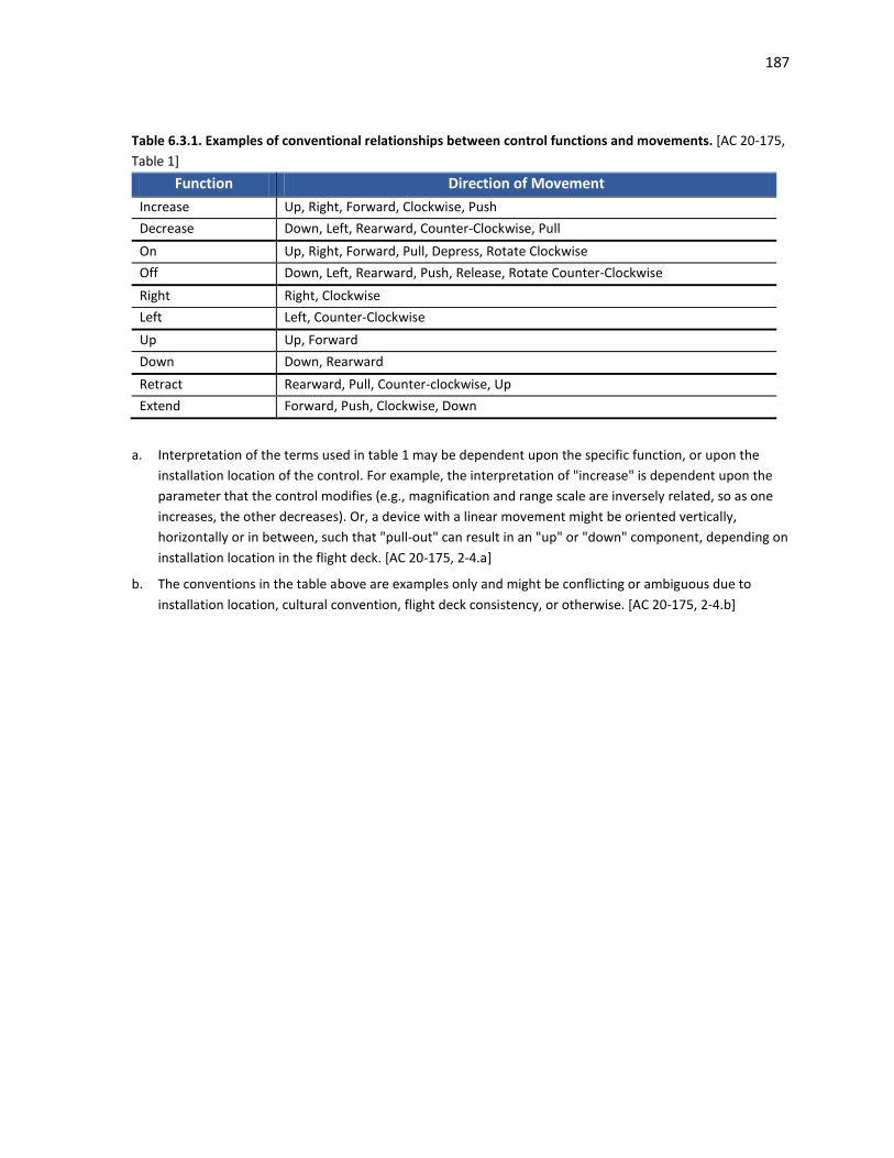
187
Table 6.3.1. Examples of conventional relationships between control functions and movements. [AC 20-175, Table 1]
Function Direction of Movement Increase Up, Right, Forward, Clockwise, Push Decrease Down, Left, Rearward, Counter-Clockwise, Pull On Up, Right, Forward, Pull, Depress, Rotate Clockwise Off Down, Left, Rearward, Push, Release, Rotate Counter-Clockwise Right Right, Clockwise Left Left, Counter-Clockwise Up Up, Forward Down Down, Rearward Retract Rearward, Pull, Counter-clockwise, Up Extend Forward, Push, Clockwise, Down
a. Interpretation of the terms used in table 1 may be dependent upon the specific function, or upon the installation location of the control. For example, the interpretation of "increase" is dependent upon the parameter that the control modifies (e.g., magnification and range scale are inversely related, so as one increases, the other decreases). Or, a device with a linear movement might be oriented vertically, horizontally or in between, such that "pull-out" can result in an "up" or "down" component, depending on installation location in the flight deck. [AC 20-175, 2-4.a]
b. The conventions in the table above are examples only and might be conflicting or ambiguous due to installation location, cultural convention, flight deck consistency, or otherwise. [AC 20-175, 2-4.b]

188
6.4 Specific Input Devices Input devices provide the means for entering information to the display system. Traditional physical controls are being integrated or replaced with virtual buttons, switches, and knobs that are drawn on the display. The selection of an input device must consider its operational suitability to the flight deck environment and the unique requirements to a particular application. In selecting the appropriate input device, it is important not only to ensure that a pilot can use the input device but also that the input device supports task performance. If the input device is not customized to both the user and the task, then control interaction could impose additional workload, increase heads-down time, and the potential for error.
This chapter presents information on the physical considerations and recommendations for the following specific input devices.
6.4.1 Rotary Controls 6.4.2 Push Buttons 6.4.3 Keyboard/Keypad 6.4.4 Switches 6.4.5 Cursor Control Devices (CCDs) 6.4.6 Touch-Screen Displays
6.4.1 Rotary Controls
FAA Regulatory and Guidance Material
Rotary Controls • Controls of a variable nature using a rotary motion must move clockwise from the off position,
through an increasing range, to the full on position. [AC 25-11A, 41.b.(1)(b)] See also: SAE ARP4102, 5.3.1.1 which is worded slightly differently. • Concentric knob assemblies should be limited to no more than two knobs per assembly. [TSO-
C165/RTCA DO-257A, 2.1.5.4] • Where knob rotation is used to control cursor movement, sequence through lists, or cause
quantitative changes, the results of such rotation should be consistent with established behavior stereotypes (Reference Sanders & McCormick, 1987) as follows: [TSO-C165/RTCA DO-257A, 2.1.5.4]
a) For X-Y cursor control (e.g., moving a pointer across the surface of the map): - Knob below or to the right of the display area: clockwise movement of the knob moves the
cursor up or to the right. - Knob above the display area: clockwise rotation of knob moves cursor up or to the left. - Knob to left of display area: clockwise rotation of knob moves cursor down or to the right. b) For quantitative displays, clockwise rotation increases values. c) For alphabet character selection or alphabetized lists, clockwise rotation sequences forward
Other Recommendation(s)
• A rotary ON-OFF function may be combined with a rotary control provided the OFF position is at the extreme counterclockwise position and is clearly identified by a distinguishable detent. Push and/or pull switching may be combined with a rotary control provided that axial motion does not cause inadvertent rotary motion. [SAE ARP4102, 5.3.1.2]

189
• When used for function selection, the selected function shall be clearly indicated and the selector position shall be identified by a distinguishable detent. [SAE ARP4102, 5.3.1.3]
• The face of the rotary control shall be clearly marked to enhance identification of the control position. [SAE ARP4102, 5.3.1.4]
• The knob pointer shall be mounted sufficiently close to its scale to minimize parallax between the pointer and scale markings. When viewed from the user's normal operator’s position, the parallax errors shall not exceed 25% of the distance between scale markings. [MIL-STD-1472G, 5.1.4.1.1.a.(6)]
Background
Knobs are recommended when low force or high precision for adjusting the value of a continuous variable is needed. However, they are especially susceptible to inadvertent activation, particularly when another knob is being manipulated, and it may be time consuming to re-establish the previous setting when the knob is turned inadvertently (McAnulty, 1995; NASA, 1995).
Example(s)
Concentric knobs are typically designed so that the one closest to the face of the panel changes cursor position, selects information category, operating/display mode, or large value changes. The inner/smaller knob is used to select among the information contents, sub categories of the position selected with the outer knob, or fine value changes.
Design guidance to maximize usability and prevent inadvertent activation is included and summarized in Table 6.4.1.1. Table 6.2.1 provides minimum edge-to-edge spacing requirements between different controls.
Table 6.4.1.1. Design guidance for rotary knobs. (McAnulty, 1995; RTCA DO-256, Appendix G) Rotary Knob Concentric Inner Knob Concentric Outer Knob
Minimum Diameter 0.375 in (10 mm) 0.875 in (22 mm) 0.5 in (13 mm) Minimum Height 0.5 in (13 mm) 0.5 in (13 mm) 0.625 in (16 mm) Minimum Displacement
N/A N/A N/A
Minimum Center-to-Center Spacing
1 in (25 mm) 2 in (51 mm) preferred
1 in (25 mm) 2 in (51 mm) preferred
1 in (25 mm) 2 in (51 mm) preferred
Setting Separation 15º 15º 15º
Minimum Resistance 4 oz (1.1 N) 4.5 oz (1.2 N) 4.5 oz (1.2 N) Maximum Resistance 12 oz (3.3 N) 6 oz (1.7 N) 6 oz (1.7 N)
Movement Clockwise to increase Clockwise to increase Clockwise to increase
Other Desirable Features
Provide feedback Serrated or knurled edges
Associated with left-most or upper-most display Serrated edges
Serrated edges

190
6.4.2 Push Buttons
Other Recommendation(s)
• A positive indication of control activation shall be provided (e.g., snap feel, audible click, or integral light). (MIL-STD-1472G; Cardosi and Murphy, 1995)
• A fixed caption push button switch should not be utilized for the selection of more than one function. For push buttons with a latched position, the IN position should provide the ON/ARMED/AUTO function. The operational/fault condition of latched or momentary push button switches shall be annunciated or be schematically explicit. [SAE ARP4102, 5.3.2]
See also: McAnulty, 1995 • The surfaces of push button controls should be concave or rough to fit the finger and to prevent
accidental slippage. (Cardosi and Murphy, 1995; MIL-STD-1472G) • A channel or cover guard shall be provided when accidental actuation of the control must be
prevented. When a cover guard is in the open position, it shall not interfere with operation of the protected device or adjacent controls. (MIL-STD-1472G, 5.1.4.2.1.a.(4))
Background
Buttons are generally recommended for discrete activation or for discrete cycling through a limited number of choices. They require a minimum amount of space and a minimum amount of time to operate, but because the setting of the button (i.e., selected or not) may be difficult to determine by position alone, they are not appropriate for discrete control where the function status is determined by position of the button alone (McAnulty, 1995; MIL-STD-1472G; NASA, 1995).
Example(s)
Design guidance to maximize usability is included and summarized in Table 6.4.2.1. Table 6.2.1 provides minimum edge-to-edge spacing requirements between different controls.
Table 6.4.2.1. Design guidance for push buttons. (McAnulty, 1995; RTCA DO-256, Appendix G) Push Button Push-Pull Button
Minimum Diameter 0.375 in (9.5 mm) 0.25 in (6 mm)
Minimum Length 0.124 in (6.4 mm) 0.75 in (19 mm)
Minimum Displacement 0.078 (2 mm) 0.5 in (13 mm)
Minimum Center-to-Center Spacing
0.75 in (19mm) horizontally
0.625 in (16 mm) vertically
1 in (25 mm)
Minimum Resistance 10 oz (2.8 N) 10 oz (2.8 N)
Maximum Resistance 40 oz (11 N) 64 oz (18 N)
Other Desirable Features
Provide feedback
Concave or friction surface
Push to activate
Increase length if dual use (e.g., if control can be rotated)

191
With the exception of push buttons for keyboards, the recommended resistance for push buttons is provided in Table 6.4.2.2.
Table 6.4.2.2. Recommended resistance for push buttons. [MIL-STD-1472G, 5.1.4.2.1.a.(5)] Single Finger Multiple Fingers Thumb or Palm
Minimum 10 oz (2.8N) 5 oz (1.4N) 10 oz (2.8N) Maximum 40 oz (11N) 20 oz (5.6N) 80 oz (23 N)

192
6.4.3 Keyboard/Keypad
FAA Regulatory and Guidance Material
• Letter keys on a keypad should be arranged alphabetically or in a QWERTY format. [TSO-C165/RTCA DO-257A, 2.1.5.3]
• If a separate numeric keypad is used, the keys should be arranged in order in a row or in a 3X3 matrix with the zero at the bottom, as shown below. [TSO-C165/RTCA DO-257A, 2.1.5.3]
7 8 9
4 5 6
1 2 3
0
1 2 3
4 5 6
7 8 9
0
Telephone Style Calculator Style • If non-alphanumeric special characters or functions are used, dedicated keys should be provided
(e.g., space, slash (/), change sign key (+/-), “clear” and “delete,” etc.). [TSO-C165/RTCA DO-257A, 2.1.5.3; RTCA DO-256, 2.1.1]
• Keypads should provide tactile feedback for any key depression. In cases when this is omitted, tactile feedback should be replaced with appropriate visual or other feedback that indicates that the system has received the inputs and is responding as expected. [AC 25.1302-1, 5-4.f.(4)] See also: AMC 25.1302, 5.3.6 which is worded slightly differently.
Other Recommendation(s)
• Systems that include more than one keyboard should maintain the same configuration for alphanumeric, numeric, and special function keys throughout the system. [MIL-STD-1472G, 5.1.3.2.5]
• A separate numeric keypad should be presented if the user must enter extensive numeric data. (Cardosi and Murphy, 1995)
• Keyboards should be composed of square keys with concave surfaces. (McAnulty, 1995) • The use of function keys on the keyboard will depend on the system. If function keys are provided,
function keys should be clearly labeled to identify the action performed. (Cardosi and Murphy, 1995) • Non-active keys on the keyboard should not be labeled. (Cardosi and Murphy, 1995) • The keyboard should be legible and readable in all lighting conditions. (Cardosi and Murphy, 1995) • Layout of virtual keyboards should be consistent between all applications on a given display. See also: Chapter 6.4.6 Touch-Screen Displays
Background
Keyboard design is important for supporting accurate and efficient data entry. The keyboard design includes characteristics such as the key size, the shape of a key, the spacing between keys, the force needed to press a key, and the feedback provided. Keyboards that are poorly designed can result in arm/muscle fatigue during use.
A logical arrangement and layout of the keys on the keyboard will minimize the potential for error. The keyboard can be arranged in a QWERTY format, so named for the six keys on the top alphabetic line. In the

193
flight deck, pilots can also use an alphabetically arranged keyboard. Consistency in the keyboard layout across flight deck systems will facilitate information entry.
Example(s)
Design guidance to maximize usability is included and summarized in Table 6.4.3.1. Table 6.2.1 provides minimum edge-to-edge spacing requirements between different controls.
Table 6.4.3.1. Design guidance for keyboards. (McAnulty, 1995; RTCA DO-256, Appendix G) Keyboard Minimum Diameter 0.385 in (10 mm) Minimum Height N/A Minimum Displacement 0.05 in (1.3 mm) Minimum Center-to-Center Spacing
0.75 in (19 mm)
Setting Separation N/A
Minimum Resistance 0.9 oz (0.25 N) 1.8 oz (0.5 N) preferred
Maximum Resistance 5.3 oz (1.5N) 2.2 oz (0.6 N) preferred
Movement N/A
Other Desirable Features Provide auditory or tactile feedback Use telephone layout for digits
194
6.4.4 Switches
FAA Regulatory and Guidance Material
Mode Annunciations • Means must be provided to indicate the current mode of operation, including any armed modes,
transitions, and reversions. Selector switch position is not an acceptable means of indication. [14 CFR 25.1329(i)] See also: 14 CFR 23.1329(h), 27.1329(f), 29.1329(f), which are worded slightly differently; Chapter
4.3.3 Annunciations Multiple System Configurations • Where multiple system configurations and more than one sensor input are available for source
selection, the switching configuration by annunciation or by selector switch position should be readily visible, readable, and should not be misleading to the pilot using the system. Labels for mode and source selection annunciators should be compatible throughout the cockpit. [AC 23.1311-1C, 18.2]
Inadvertent Activation • Particular attention should be given to the placement of switches or other control devices, relative
to one another, so as to minimize the potential for inadvertent incorrect crew action, especially during emergencies or periods of high workload. [AC 25.1309-1A, 8.g.(5)]
• The design should provide a way to discourage irreversible errors that have potential safety implications. Acceptable ways to discourage errors include switch guards, interlocks, or multiple confirmation actions. As an example, generator drive controls on many airplanes have guards over the switches to discourage inadvertent actuation, because once the drives are disengaged, they cannot be re-engaged while in flight or with the engine running. An example of multiple confirmations would be the presentation of a temporary flight plan that the flightcrew can review before accepting. [AC 25.1302-1, 5-7.e.(1)]
See also: AMC 25.1302, 5.6.5 which is worded slightly differently.
Other Recommendation(s)
• An indication of control actuation shall be provided (e.g., snap feel, audible click, or associated or integral light). [MIL-STD-1472G, 5.1.4.2.1.c.(4)]
• A three-position rocker switch is generally not recommended because the setting may be difficult to read. (McAnulty, 1995)
Toggle Switches • Toggle switches should be vertically oriented with OFF in the down position. Horizontal orientation
and actuation of toggle switches shall be used only for compatibility with the controlled function or equipment location. [MIL-STD-1472G, 5.1.4.2.1.c.(5)]
• If a third position is used on a toggle switch to indicate “off”, the off setting should be in the center position, except where such implementation would compromise performance. In that case, the off setting should be at the bottom. (NASA, 1995)
Rocker Switches • Where practicable, rocker switches shall be vertically oriented. Actuation of the upper wing shall
turn the equipment or component on, cause the quantity to increase, or cause the equipment of component to move forward, clockwise, to the right or up. Horizontal orientation of rocker switches
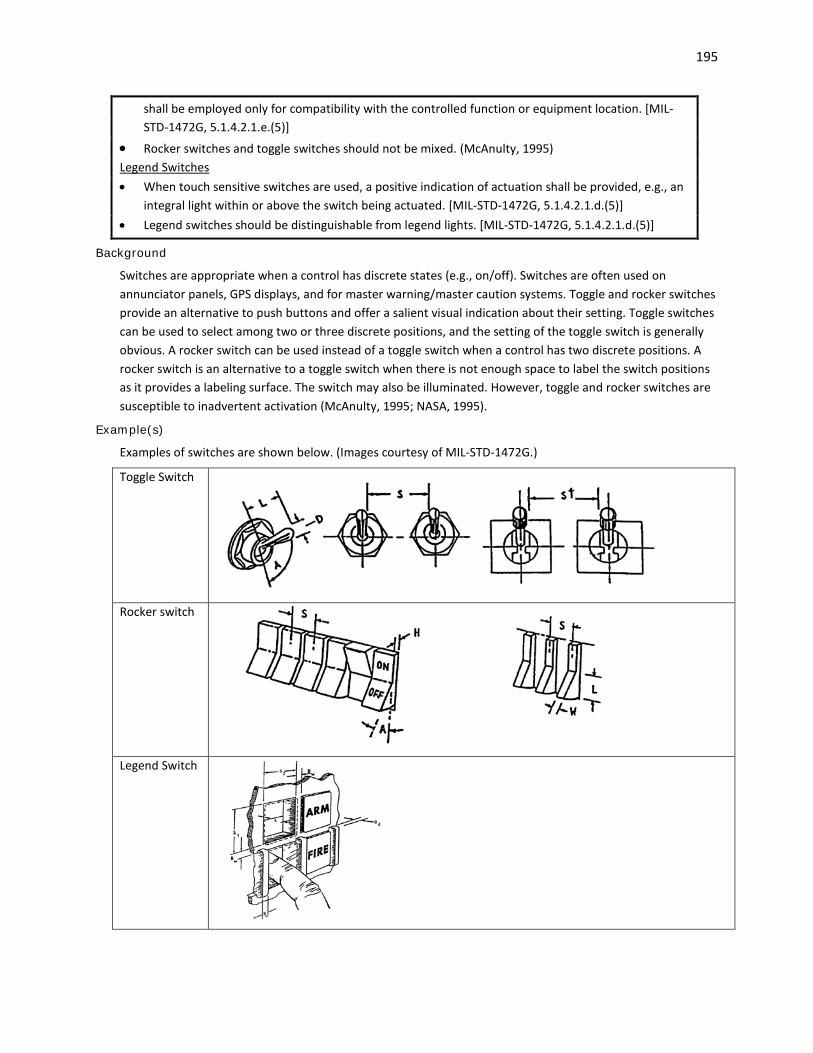
195
shall be employed only for compatibility with the controlled function or equipment location. [MIL-STD-1472G, 5.1.4.2.1.e.(5)]
• Rocker switches and toggle switches should not be mixed. (McAnulty, 1995) Legend Switches • When touch sensitive switches are used, a positive indication of actuation shall be provided, e.g., an
integral light within or above the switch being actuated. [MIL-STD-1472G, 5.1.4.2.1.d.(5)] • Legend switches should be distinguishable from legend lights. [MIL-STD-1472G, 5.1.4.2.1.d.(5)]
Background
Switches are appropriate when a control has discrete states (e.g., on/off). Switches are often used on annunciator panels, GPS displays, and for master warning/master caution systems. Toggle and rocker switches provide an alternative to push buttons and offer a salient visual indication about their setting. Toggle switches can be used to select among two or three discrete positions, and the setting of the toggle switch is generally obvious. A rocker switch can be used instead of a toggle switch when a control has two discrete positions. A rocker switch is an alternative to a toggle switch when there is not enough space to label the switch positions as it provides a labeling surface. The switch may also be illuminated. However, toggle and rocker switches are susceptible to inadvertent activation (McAnulty, 1995; NASA, 1995).
Example(s)
Examples of switches are shown below. (Images courtesy of MIL-STD-1472G.)
Toggle Switch
Rocker switch
Legend Switch
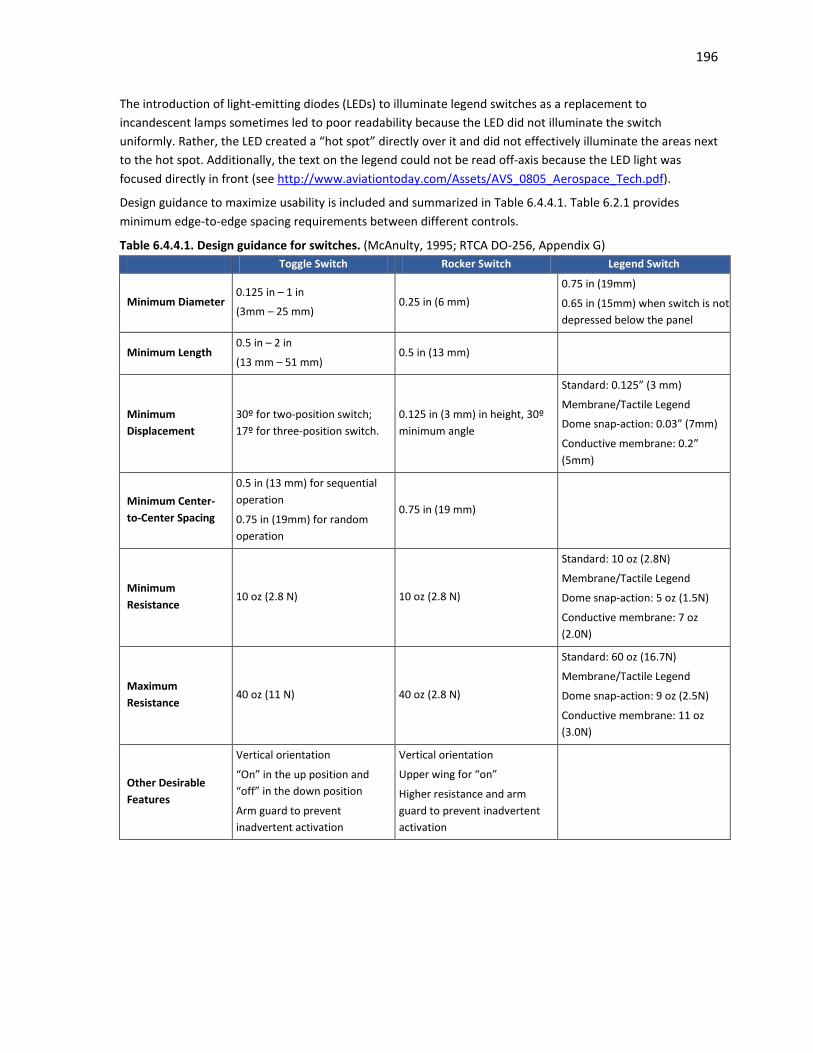
196
The introduction of light-emitting diodes (LEDs) to illuminate legend switches as a replacement to incandescent lamps sometimes led to poor readability because the LED did not illuminate the switch uniformly. Rather, the LED created a “hot spot” directly over it and did not effectively illuminate the areas next to the hot spot. Additionally, the text on the legend could not be read off-axis because the LED light was focused directly in front (see http://www.aviationtoday.com/Assets/AVS_0805_Aerospace_Tech.pdf).
Design guidance to maximize usability is included and summarized in Table 6.4.4.1. Table 6.2.1 provides minimum edge-to-edge spacing requirements between different controls.
Table 6.4.4.1. Design guidance for switches. (McAnulty, 1995; RTCA DO-256, Appendix G) Toggle Switch Rocker Switch Legend Switch
Minimum Diameter 0.125 in – 1 in
(3mm – 25 mm) 0.25 in (6 mm)
0.75 in (19mm)
0.65 in (15mm) when switch is not depressed below the panel
Minimum Length 0.5 in – 2 in
(13 mm – 51 mm) 0.5 in (13 mm)
Minimum Displacement
30º for two-position switch; 17º for three-position switch.
0.125 in (3 mm) in height, 30º minimum angle
Standard: 0.125” (3 mm)
Membrane/Tactile Legend
Dome snap-action: 0.03” (7mm)
Conductive membrane: 0.2” (5mm)
Minimum Center-to-Center Spacing
0.5 in (13 mm) for sequential operation
0.75 in (19mm) for random operation
0.75 in (19 mm)
Minimum Resistance
10 oz (2.8 N) 10 oz (2.8 N)
Standard: 10 oz (2.8N)
Membrane/Tactile Legend
Dome snap-action: 5 oz (1.5N)
Conductive membrane: 7 oz (2.0N)
Maximum Resistance
40 oz (11 N) 40 oz (2.8 N)
Standard: 60 oz (16.7N)
Membrane/Tactile Legend
Dome snap-action: 9 oz (2.5N)
Conductive membrane: 11 oz (3.0N)
Other Desirable Features
Vertical orientation
“On” in the up position and “off” in the down position
Arm guard to prevent inadvertent activation
Vertical orientation
Upper wing for “on”
Higher resistance and arm guard to prevent inadvertent activation

197
6.4.5 Cursor Control Devices (CCDs)
FAA Regulatory and Guidance Material
• A key benefit of CCDs is their convenience; they are typically located on or close to the pilots' natural hand position, and often accompanied by a hand stabilizer or arm rest. This allows for convenient pilot inputs, particularly since hand and arm motion is minimized due to high device gain. However, CCDs can also lead to control errors, particularly when subject to vibration environments. Also CCD inputs are more likely to go unnoticed by other crew members because pilot inputs are typically accomplished with small finger motions on the CCD. Consider effects on flightcrew coordination in the environment and use conditions of CCDs. [AC 20-175, 3-4.a]
• The graphical user interface (GUI) and control device should be compatible with the airplane system they will control. The hardware and software design assurance levels and tests for the GUI and control device should be commensurate with the level of criticality of the airplane system they will control. [AC 25-11A, 41.b.(2)(b).1]
• The CCD design and installation should enable the flightcrew to operate the CCD without exceptional skill during foreseeable flight conditions, both normal and adverse (for example, turbulence and vibrations). Certain selection techniques, such as double or triple clicks, should be avoided. [AC 25-11A, 41.c.(1)]
• The safety assessment of the CCD should address reversion to alternate means of control following loss of the CCD. This includes an assessment on the impact of the failure on flightcrew workload. [AC 25-11A, 41.c.(2)]
• The functionality of the CCD should be demonstrated with respect to the flightcrew interface considerations outlined below: [AC 25-11A, 41.c.(3)]
(a) The ability of the flightcrew to share tasks, following CCD failure, with appropriate workload and efficiency.
(b) The ability of the flightcrew to use the CCD with accuracy and speed of selection required of the related tasks, under foreseeable operating conditions (for example, turbulence, engine imbalance, and vibration).
(c) Satisfactory flightcrew task performance and CCD functionality, whether the CCD is operated with a dominant or non-dominant hand.
(d) Hand stability support position (for example, wrist rest). (e) Ease of recovery from incorrect use. • The cursor symbol should be restricted from areas of primary flight information or where occlusion
of display information by a cursor could result in misinterpretation by the flightcrew. If a cursor symbol is allowed to enter a critical display information field, it should be demonstrated that the cursor symbol’s presence will not cause interference during any phase of flight or failure condition. [AC 25-11A, 41.d.(1)]
See also: AC 20-175, 3-4.e which is worded slightly differently. • Presentation of the cursor should be clear, unambiguous, and easily detectable in all foreseeable
operating conditions. [AC 25-11A, 41.d.(2)(a)] See also: NASA, 1995 • The failure mode of an uncontrollable and distracting display of the cursor should be evaluated. [AC
25-11A, 41.d.(2)(b)] • Because in most applications more than one flightcrew member will be using one cursor, the
applicant should establish an acceptable method for handling “dueling cursors” that is compatible
198
with the overall flight deck philosophy (for example, “last person on display wins”). Acceptable methods should also be established for handling other possible scenarios, including the use of two cursors by two pilots. [AC 25-11A, 41.d.(2)(c)]
• If more than one cursor is used on a display system, a means should be provided to distinguish between the cursors. [AC 25-11A, 41.d.(2)(d); AC 20-175, 3-4.c]
• Ensure that the cursor symbol is readily discernable from other information, and readily located on the electronic displays. This is particularly important if a cursor symbol is allowed to fade from a display. Some methods to enhance quick location of the cursor are “blooming” or “growing” it to attract the flightcrew’s attention.[AC 20-175, 3-4.b]
• If a cursor is allowed to fade from a display, some means should be employed for the flightcrew to quickly locate it on the display system. [AC 25-11A, 41.d.(2)(e)]
• Do not allow the cursor symbol to creep or move without pilot input. Exceptions can include automatic cursor positioning, if it can be shown that it does not result in pilot confusion or unacceptable task completion time. [AC 20-175, 3-4.d]
• In multi-crew aircraft, most applications will allow more than one flightcrew member to use one cursor. Establish an acceptable method for handling simultaneous “dueling cursors” that is compatible with the overall flight deck philosophy. Establish acceptable methods for other possible scenarios, including the use of two cursors by two pilots. [AC 20-175, 3-4.f]
• Labels of graphical controls accessed by a cursor device such as a trackball should be included on the graphical display. When menus lead to additional choices such as submenus, the menu label should provide a reasonable description of the next submenu. [AC 25.1302-1, 5-4.c.(2)(a)]
See also: AMC 25.1302, 5.3.3.b which is worded slightly differently; Chapter 6.1 Controls: General
Other Recommendation(s)
• The same level of performance should be achieved with cursor control devices as with conventional controls. [N 8110.98]
• The CCD should allow for both fast movement and accurate placement. (Smith and Mosier, 1986). • The cursor should not move beyond the outer boundaries of the screen nor should it disappear from
sight. (Ahlstrom and Longo, 2003) • The cursor symbol should not obstruct any required information. • The cursor symbol should not be distracting, e.g., when searching for information in a separate
location on the display unrelated to the position of cursor symbol. (NASA, 1995, 9.6.3.2.1) • The shapes used for the cursor symbol should be unique and easily distinguishable from other
symbols. The cursor symbol and function should be consistent. Cursor symbols that are different should perform different functions. (NASA, 1995, 9.6.3.2.1)
• Active areas on the display should be positioned so that the pilot can select them without obscuring critical information.
• Active areas on the display (e.g., touch screen controls) should be sized to permit accurate selection with the pointing/cursor-control device in the flight deck environment under all operating conditions (e.g., turbulence) (Chandra, et al., 2003)
• The system should use a pointing cursor to indicate the focus of input or attention within a display, and a place holding cursor to indicate the location within a data field where text can be entered. (NASA, 1995, 9.6.3.2.1)
• Pointing cursors should not blink or flash. The size and image quality of the pointing cursor should be consistent across all display locations. (NASA, 1995)

199
• The movement of the pointing cursor should appear smooth. Cursors should not move without user input. (NASA, 1995)
• There should only be one place holding cursor on a display page. (NASA, 1995. 9.6.3.2.1.2) • If blinking is used to call attention to the place holding cursor, the default blink rate should be 3 Hz. If
the blink rate is user-selectable, the blink rate should be between 3 to 5 Hz. (NASA, 1995, 9.6.3.2)
Background
Cursor Control Devices (CCD; such as a mouse, trackball, joystick, touch pad, or stylus) present unique issues to consider in terms of their usability. First, CCDs are multi-purpose controls so one device may be used to control a wide variety of functions. Consequently, functions that were once immediately accessible using discrete controls (e.g., by turning a single knob) may instead require the flightcrew to step through a series of menus. This sequence of steps will most likely take longer than executing a single action, increasing the time needed to complete a task. Second, it may be difficult to use the CCD with high precision in all operating conditions, e.g., navigating through a series of menus in turbulence or under time pressure. The attention required to locate and access a function with a CCD may increase workload and heads-down time relative to use of a single dedicated control. Finally, it may not be obvious which control function is active or available if labels for CCD controls are presented only on the display screen. It will be important that the pilot be able to quickly identify the active function based on the cursor’s position and what function it will perform. Before implementing CCDs, its use should be compared to conventional controls to understand the potential impact on task performance time and workload. (See AC 20-145 for more information.)
Example(s)
Slow visual feedback may lead to misjudgments in where the cursor is actually placed. A system response within 75 milliseconds is generally acceptable, whereas delays greater than 120 milliseconds may be perceived as being unacceptable (Avery, et al., 1999).
One method for showing the location of the cursor when it moves from one flight deck display window into another is to highlight the cursor with a circle.

200
6.4.6 Touch-Screen Displays
FAA Regulatory and Guidance Material
• The location of the pilot’s finger touch, as sensed by the touch screen, should be predictable and obvious. [AC 20-175, 3-5.d]
• If a touch screen’s calibration can drift or degrade, provide touch screen calibration procedures and other maintenance-related items to ensure proper calibration and operation. Include these procedures in the instructions for continued airworthiness, per § 2X.1529. [AC 20-175, 3-5.c]
• Consider integrating an associated support for stabilizing the pilot's hand, and for providing a reference point when positioning fingers, if appropriate. Ensure that touch screens do not result in unacceptable levels of workload, error rates, speed, and accuracy. [AC 20-175, 3-5.a]
• Ensure that touch screens resist scratching, hazing, or other damage that can occur through normal use. Demonstrate that the system will continue to provide acceptable performance after long-term use and exposure to skin oils, perspiration, environmental elements (e.g., sun), impacts (e.g., clipboard), chemical cleaners that might be used in the flight deck, and any liquids that might be brought onboard by flightcrew members (e.g., coffee). [AC 20-175, 3-5.b]
Other Recommendation(s)
• A touch screen is not appropriate for tasks that require pilots to have their arms raised and unsupported for long periods of time. (Cardosi and Murphy, 1995)
• The touch-sensitive areas should be clearly indicated on the display. (NASA, 1995, 9.3.3.4.7) • If more than one input device can be used to enter information, the user should not have to switch
frequently between the touch screen and other input devices. Switching between the input devices should not impose additional workload. (NASA, 1995)
• Soft keys on the touch-screen display should have a region around them where touches are not recognized to prevent inadvertent activation. (Beringer and Peterson, 1985).
• Feedback should be provided within 100 ms to indicate that a touch has been received (Cardosi and Murphy, 1995; NASA, 1995, 9.3.3.4.7). This feedback can be tactile, auditory or visual in nature.
• A soft key button should activate only when it is pressed and released. If a button is pressed but not released (e.g., a user drags his/her finger away before releasing it), the button should not activate. Additionally, the area where the finger was released should not activate.
• Soft keys displayed on a touch screen should have a minimum size of 22mm across (this recommended size assumes correction to reduce touch bias resulting from parallax errors). (Lewis, 1993; Sears, 1991)
• The angle of the touch screen display to the user should be adjustable. If the display is fixed, the touch screen display should be positioned at a 30° angle from horizontal and no greater than 45° from horizontal. Angles greater than 45° may lead to fatigue. (Lewis, 1993)
• To minimize parallax errors, the touchscreen should be mounted as close as possible to a position perpendicular to the pilot’s line of sight. (Beringer and Bowman, 1989)
• If the display requires a minimum amount of pressure to register a touch, the pressure should not cause strain during prolonged periods of usage.
• Active areas on the display should be positioned so that the pilot can select them without obscuring critical information.
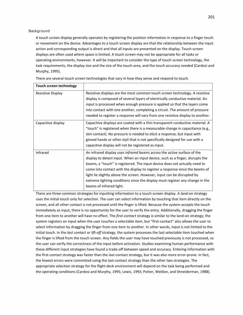
201
Background
A touch screen display generally operates by registering the position information in response to a finger touch or movement on the device. Advantages to a touch screen display are that the relationship between the input action and corresponding output is direct and that all inputs are presented on the display. Touch screen displays are often used where space is limited. A touch screen may not be appropriate for all tasks or operating environments, however. It will be important to consider the type of touch screen technology, the task requirements, the display size and the size of the touch area, and the touch accuracy needed (Cardosi and Murphy, 1995).
There are several touch screen technologies that vary in how they sense and respond to touch.
Touch screen technology
Resistive Display Resistive displays are the most common touch screen technology. A resistive display is composed of several layers of electrically conductive material. An input is processed when enough pressure is applied so that the layers come into contact with one another, completing a circuit. The amount of pressure needed to register a response will vary from one resistive display to another.
Capacitive display Capacitive displays are coated with a thin transparent conductive material. A “touch” is registered when there is a measurable change in capacitance (e.g., skin contact). No pressure is needed to elicit a response, but input with gloved hands or other styli that is not specifically designed for use with a capacitive display will not be registered as input.
Infrared An infrared display uses infrared beams across the active surface of the display to detect input. When an input device, such as a finger, disrupts the beams, a “touch” is registered. The input device does not actually need to come into contact with the display to register a response since the beams of light lie slightly above the screen. However, input can be disrupted by extreme lighting conditions since the display must register any change in the beams of infrared light.
There are three common strategies for inputting information to a touch-screen display. A land-on strategy uses the initial touch only for selection. The user can select information by touching that item directly on the screen, and all other contact is not processed until the finger is lifted. Because the system accepts the touch immediately as input, there is no opportunity for the user to verify the entry. Additionally, dragging the finger from one item to another will have no effect. The first-contact strategy is similar to the land-on strategy; the system registers an input when the user touches a selectable item, but “first-contact” also allows the user to select information by dragging the finger from one item to another. In other words, input is not limited to the initial touch. In the last contact or lift-off strategy, the system processes the last selectable item touched when the finger is lifted from the touch screen. Any fields the user may have touched previously is not processed, so the user can verify the correctness of the input before activation. Studies examining human performance with these different input strategies have found a trade-off between speed and accuracy. Entering information with the first-contact strategy was faster than the last-contact strategy, but it was also more error-prone. In fact, the fewest errors were committed using the last-contact strategy than the other two strategies. The appropriate selection strategy for the flight deck environment will depend on the task being performed and the operating conditions (Cardosi and Murphy, 1995; Lewis, 1993; Potter, Weldon, and Shneiderman, 1988).

202
Text entry via a touch screen keyboard is slower than a standard keyboard (25 words per minute versus 58 words per minute, respectively, using a QWERTY layout), but typing speed can be improved with more experience or more responsive technology. One factor that contributed to the lower typing rate was the inability of the touch screen display to process simultaneous multiple inputs (Sears, 1991). The keyboard layout may also facilitate text entry on a touch screen; a comparison of layouts for one-finger typing or stylus entry, as is common with touch screens, indicated that a roughly square (5x5) alphabetic keyboard layout facilitated text entry compared to a conventional QWERTY keyboard layout because the average distance between keys was smaller (Lewis, Kennedy, and LaLomia, 1992 in Lewis, 1993).
Example(s)
In determining whether to use touch screen technology, consider factors such as the speed of the response required (and how quickly a response can be made); the force required for the input, the type of feedback provided, and the risks of inadvertent activation. That is, a pilot may be able to enter information effectively to a display system using a touch screen display, but if this data entry task requires a high level of precision, head-down time may increase considerably (Cardosi and Murphy, 1995).
There are several issues unique to the design and use of virtual, “soft” controls. Unlike hard controls, soft controls generally do not provide tactile and/or auditory feedback that can be used as a cue to indicate when a function has been activated. Additionally, while hard controls for a display system are generally located in close proximity (e.g., on a dedicated control panel), the location of soft controls may be more varied, and the size of the control constrained by the display real estate. Accessibility of soft controls may also be hindered by display parallax, such that it may be difficult to determine the “active” area (Degani, Palmer, and Bauersfeld, 1992).
Parallax is a difference between the location where users perceive where they can touch and the actual location to touch. Parallax can result in a bias along both the x- and y- axes, and the amount of bias generally varies as a function of the angle of the display. Mounting the display perpendicular to the pilot’s line of sight can minimize touch bias (Beringer and Bowman, 1989).
Several studies have been conducted to examine the appropriate key size for a touch screen display. The methodology used for these studies generally require participants to touch some sort of target on the display (e.g., square buttons). The distance between the first touch and the target location can then be measured to determine the key size needed to capture the touches. The collective results of these studies indicate that without correction for touch bias, the minimum key size was approximately 26 mm to achieve a 99% touch accuracy. After correcting for touch bias, the minimum key size was approximately 22 mm for a 99% touch accuracy. The size of the touch screen keys and spacing between keys may need to be increased to accommodate input with gloves (Sears, 1991; Lewis, 1993).

203
7 Design Philosophy
FAA Regulatory and Guidance Material
General • The applicant should establish, document, and follow a design philosophy for the display system that
supports the intended functions (§ 25.1301). The design philosophy should include a high level description of: [AC 25-11A, 11.a]
(1) General philosophy of information presentation – for example, is a “quiet, dark” flight deck philosophy used or is some other approach used?
(2) Color philosophy on the electronic displays – the meaning and intended interpretation of different colors – for example, does magenta always represent a constraint?
(3) Information management philosophy – for example, when should the pilot take an action to retrieve information or is it brought up automatically? What is the intended interpretation of the location of the information?
(4) Interactivity philosophy - for example, when and why is pilot confirmation of actions requested? When is feedback provided?
(5) Redundancy management philosophy – for example, how are single and multiple display failures accommodated? How are power supply and data bus failures accommodated?
See also: Chapter 8 Intended Function • Display information should be presented so it is consistent with the flight deck design philosophy in
terms of symbology, location, control, behavior, size, shape, color, labels, dynamics and alerts. [AC 25-11A, 31.b]
• Prior to defining the characteristics (color, symbology, etc.) or standards to be used on a specific display, a flight deck design philosophy should be established. Additionally, displays should be consistent across all systems in the flight deck. Documentation of the usage for display philosophy would help establish the working basis for determining compliance. [AC 27-1B, AC 27.1303b(4)(ii)(B)(1)(v); AC 29-2C, AC 29.1303b(4)(ii)(B)(1)(v)]
• Data entry methods, color-coding philosophies, and symbology should be as consistent as possible across the various applications. [AC 120-76B, 12.m.(1)]
See also: Chapter 3.1 Electronic Display Information Elements and Features: General; Chapter 9 Error Management, Prevention, Detection, and Recovery
Controls See also: Chapter 6 Controls • Document and follow a design philosophy for controls, which supports the intended functions (14
CFR 2x.1301). The documented design philosophy may be included as part of a system description, certification plan, or other document that is submitted to the FAA during a certification project. The design philosophy should include a high level description of controls features, such as labeling, feedback, automated behavior, and error recovery. Also include a high level description of human performance considerations, such as flightcrew workload, error potential, and expected training requirements. [AC 20-175, 2-1.a]
See also: Chapter 8 Intended Function • Apply a particular design philosophy consistently throughout the flight deck to the greatest extent
practicable. [AC 20-175, 2-1.b]

204
• Consider a variety of environments, use conditions, and other factors that can impact flightcrew interaction with controls during aircraft operations that can be reasonably expected in service, including [AC 20-175, 2-2.a]:
- Information population; - Bright and dark lighting conditions; - Use of gloves; - Turbulence and other vibrations; - Interruptions and delays in tasks; - Objects that may physically interfere with the motion of a control; - Incapacitation of one pilot (multi-crew aircraft); - Use of the non-dominant hand; and - Excessive ambient noise. • If color is used for coding task-essential information, use at least one other distinctive coding
parameter (e.g., size, shape, label). Whenever possible, color coding should be consistent across all controls and displays. Consider the effect of flight deck lighting on the appearance of the label, and the use of colors throughout the flight deck (i.e., color philosophy). [AC 20-175, 2-7.c]
See also: Chapter 3.1 Electronic Display Information Elements and Features: General; Chapter 3.7 Color; Chapter 6 Controls
• Title 14 CFR 2X.1529 requires instructions for continued airworthiness of equipment. Include any limitations or considerations for the conditions in which controls are operated, replaced, or serviced. For example [AC 20-175, 2-12.a]:
- How should controls be serviced to ensure continued compliance with 14 CFR 2X.671, requiring easy, smooth, positive operation?
- Will controls need cleaning from skin oils and perspiration, in order for labels to be legible? - What type of interference may impede safe operation? - Is the control susceptible to failure if exposed to liquids (e.g., spilled coffee or soda)? - What maintenance or inspection should be conducted over a given time interval? • Design controls to minimize degradation (e.g., scratching, hazing) from operational use. [AC 20-175,
2-12.b] • Define a reasonable maintenance and inspection interval for each control, along with verification
tests that are conducted at each interval in the instructions for continued operational safety. [AC 20-175, 2-12.c]
Other Recommendation(s)
• A style guide should document methods for designing the user interface elements (e.g., windows, menus, and pop-up information) and standard methods for performing common actions (e.g., opening and closing windows).
Background
A system design philosophy provides a high level description of human-centered design principles that can be used to guide system development and improve simplicity and safety. Establishing such a philosophy can help change the focus from purely technological issues during the design process to highlight user interface issues with respect to flightcrew performance and ensure that a consistent interface is presented. Even if the flightcrew only has an implicit understanding of the design philosophy, they will develop expectations

205
regarding how displays will behave based on their experience with that flight deck. Systems that are designed in accordance with the overall flight deck design philosophy will reduce the likelihood of errors.
Example(s)
Boeing’s flight deck design philosophy includes the following key elements (McKenzie, 2003): Automation should serve as an aid to the pilot, rather than as a replacement. New technologies and functional capabilities should be used only when they clearly benefit operations or
efficiency, and when there is no adverse effect on the human-machine interface. The pilot is the final authority for operating the aircraft. Both crew members are ultimately responsible for safe flight. Systems should be error tolerant. The hierarchy of design alternatives is: crew operation simplicity, equipment redundancy, and
automation. Design for crew operations should be based on pilots’ operational experience and previous training.

This page left blank intentionally.

207
8 Intended Function
FAA Regulatory and Guidance Material
General • Each item of installed equipment must be of a kind and design appropriate to its intended function
[14 CFR 23.1301(a); 25.1301(a); 27.1301(a); 29.1301(a)] • The equipment, systems, and installations whose functioning is required by this subchapter must be
designed and installed to ensure that they perform their intended functions under any foreseeable operating condition. [14 CFR 25.1309(a); 29.1309(a)]
See also: 14 CFR 27.1309(a) which is worded slightly differently. • The airplane equipment and systems must be designed and installed so that: [14 CFR 23.1309(a)] (1) Those required for type certification or by operating rules perform as intended under the
airplane operating and environmental conditions, including the indirect effects of lightning strikes.
(2) Any equipment and system does not adversely affect the safety of the airplane or its occupants, or the proper functioning of those covered by paragraph (a)(1) of this section.
• The airplane systems and associated components, considered separately and in relation to other systems, must be designed so that: [14 CFR 25.1309(b)]
(1) The occurrence of any failure condition which would prevent the continued safe flight and landing of the airplane is extremely improbable, and
(2) The occurrence of any other failure conditions which would reduce the capability of the airplane or the ability of the crew to cope with adverse operating conditions is improbable.
See also: 14 CFR 29.1309(b) which is worded slightly differently and 14 CFR 23.1309(b) which is significantly different.
• The equipment, systems, and installations of a multiengine rotorcraft must be designed to prevent hazards to the rotorcraft in the event of a probable malfunction or failure. [14 CFR 27.1309(b)]
• The equipment, systems, and installations of single-engine rotorcraft must be designed to minimize hazards to the rotorcraft in the event of a probable malfunction or failure. [14 CFR 27.1309(c)]
• This section applies to installed systems and equipment intended for flightcrew members' use in operating the airplane from their normally seated positions on the flight deck. The applicant must show that these systems and installed equipment, individually and in combination with other such systems and equipment, are designed so that qualified flightcrew members trained in their use can safely perform all of the tasks associated with the systems' and equipment's intended functions. [14 CFR 25.1302]
• Section 25.1301(a) requires each item of installed equipment must “be of a kind and design appropriate to its intended function.” Section 25.1302 establishes requirements to ensure the design supports flightcrew members’ ability to perform all tasks associated with a system’s intended function. For the applicant to show compliance with § 25.1302, the intended function of a system and the associated flightcrew tasks expected of the flightcrew must be described. [AC 25.1302-1, 5-3.a]
Demonstrating Compliance • To comply with § 25.1302 the applicant’s statement of intended function must be sufficiently
specific and detailed that the FAA can evaluate whether that system is appropriate for the intended function(s) and the associated flightcrew tasks. For example, a statement that a new display system

208
is intended to “enhance situation awareness” must be further explained. A wide variety of different displays enhance situation awareness in different ways. Examples are terrain awareness displays, vertical profile displays, and even the primary flight displays. The applicant may also need to provide more detailed descriptions for designs with greater levels of novelty, complexity, or integration. [AC 25.1302-1, 5-3.b]
• An applicant must describe intended functions and associated tasks for equipment. This type of information is of the level typically provided in a pilot handbook or an operations manual. It would describe indications, controls, and flightcrew procedures. Compliance to § 25.1302 must be shown for: [AC 25.1302-1, 5-3.c]
(1) each item of flightdeck equipment; (2) flightcrew indications and controls for that equipment; and (3) individual features or functions of that equipment. • Novel features may require the applicant provide more detailed information to show compliance,
while previously approved systems and features typically require less. Subchapter 4-2 discusses when functions are sufficiently novel that function(s) and associated task(s) are sufficiently specific and detailed by using the following questions: [AC 25.1302-1, 5-3.d]
(1) Does each feature and function have a stated intent? (2) Are flightcrew tasks associated with the function described? (3) What assessments, decisions, and actions are flightcrew members expected to make based on
information provided by the system? (4) What other information is assumed to be used in combination with the system? (5) Will installation or use of the system interfere with the ability of the flightcrew to operate other
flightdeck systems? (6) Are there any assumptions made about the operational environment in which the equipment
will be used? (7) What assumptions are made about flightcrew attributes or abilities beyond those required in
regulations governing flight operations, training, or qualification? • To comply with this integration requirement, all flightdeck equipment must be usable by the
flightcrew to perform all tasks associated with the intended functions, in any combination reasonably expected in service. Flightdeck equipment includes interfaces to airplane systems the flightcrew interacts with, such as controls, displays, indications, and annunciations. [AC 25.1302-1, 5-8.a.(2)]
Display Size • A display should be large enough to present information in a form that is usable (for example,
readable or identifiable) to the flightcrew from the flightcrew station in all foreseeable conditions, relative to the operational and lighting environment and in accordance with its intended function(s). [AC 25-11A, 16.a.(1)] See also: Chapter 2.1 Visual Display Characteristics
Viewing Envelope • The installed display must not visually obstruct other controls and instruments or prevent those
controls and instruments from performing their intended function (§ 25.1301). [AC 25-11A, 16.b.(9)] See also: AMC 25.1302, 5.4.2.c which is worded slightly differently.
• The applicable flightcrew members, seated at their stations and using normal head movement, must be able to see and read display format features such as fonts, symbols, icons and markings so they can safely perform their tasks. In some cases, cross-flight-deck readability may be required to meet
209
the intended function (§ 25.1301(a)) that both pilots must be able to access and read the display. [AC 25.1302-1, 5-5.b.(2)]
See also: Chapter 2.2 Display Installation and Integration; Chapter 2.3 Field-of-View; Chapter 3.4 Markings, Dials, Tapes, and Numeric Readouts
Consistency on the Flight Deck • Display information representing the same thing on more than one display on the same flight deck
should be consistent. Acronyms and labels should be used consistently, and messages/annunciations should contain text in a consistent way. Inconsistencies should be evaluated to ensure that they are not susceptible to confusion or errors, and do not adversely impact the intended function of the system(s) involved. [AC 25-11A, 31.b]
See also: AMC 25.1302, 5.4.2(b) which is worded slightly differently; Wright and Barlow, 1995; Chapter 3.1 Electronic Display Information Elements and Features: General; Chapter 3.2 Labels
• Acronyms and labels should be used consistently, and messages/annunciations should contain text in a consistent way. Inconsistencies should be evaluated to ensure that they are not susceptible to confusion or errors, and do not adversely impact the intended function of the system(s) involved. [AC 25-11A, 31.b]
See also: Chapter 3.2 Labels • Electronic displays in the cockpit should use symbology consistent with their intended function. [AC
23.1311-1C, 17.1] See also: Chapter 3.3 Symbols • Inconsistencies in the use of color should be evaluated to ensure that they are not susceptible to
confusion or errors, and do not adversely impact the intended function of the system(s) involved. [AC 25-11A, 31.c.(5)(b)]
See also: Chapter 3.7 Color Graphical Depictions/Images • Image distortion should not compromise image interpretation. Images meant to provide information
about depth (for example, 3-Dimensional type perspective displays) should provide adequate depth information to meet the intended function. [TSO-C113a/SAE AS8034B, 4.2.8]
See also: Chapter 3.3 Symbols • Images should be of sufficient size and include sufficient detail to meet the intended function. The
pilots should be able to readily distinguish the features depicted. [AC 25-11A, 31.g.(1)] See also: Chapter 3.5 Graphical Depictions and Images
• The source and intended function of the image and the level of operational approval for using the image should be provided to the pilots. This can be accomplished using the airplane flight manual, image location, adequate labeling, distinct texturing, or other means. [AC 25-11A, 31.g.(1)] See also: Chapter 3.5 Graphical Depictions and Images
• Image distortion should not compromise image interpretation. Images meant to provide information about depth (for example, 3-Dimensional type perspective displays) should provide adequate depth information to meet the intended function. [AC 25-11A, 31.g.(2)]
See also: Chapter 3.5 Graphical Depictions and Images • Terrain and airport information must be accurate and of acceptable resolution in order for the
system to perform its intended function. Terrain data should be gridded at 30 arc seconds with 100-foot resolution within 30 NM of all airports with runway lengths of 3500 feet or greater, and whenever necessary (particularly in mountainous environments), 15 arc seconds with 100-foot resolution (or even 6 arc seconds) within 6 NM of the closest runway. It is acceptable to have terrain

210
data gridded in larger segments over oceanic and remote areas around the world. [TSO-C151c, Appendix 1, 6.3]
Note: Class B equipment may require information relative to airports with runways less than 3500 feet whether public or private. Small airplane owners and operators, as well as small non-scheduled part 135 operators, will likely be the largest market for Class B equipment and they frequently use airports of less than 3500 feet. Those TAWS manufacturers who desire to sell to this market must be willing to customize their terrain databases to include selected airports used by their customers. [TSO-C151c, Appendix 1, 6.3]
See also: Chapter 3.6 Map Database and Accuracy • When information elements temporarily obscure other information, the resultant loss of
information should not cause a hazard in accordance with the obscured information’s intended function. [AC 25-11A, 31.e.(1)] See also: Chapter 3.8 Integrated Display Issues
• When fusing or overlaying multiple images, the resultant combined image should meet its intended function despite any differences in image quality, projection, data update rates, sensitivity to sunlight, data latency, or sensor alignment algorithms. When conforming an image to the outside world, such as on a HUD, the image should not obscure or significantly hinder the flightcrew’s ability to detect real world objects. An independent brightness control of the image may help satisfy this guideline. Image elements that correlate or highlight real world objects should be sufficiently coincident to avoid interpretation error or significantly increase interpretation time. [AC 25-11A, 31.g.(5)] See also: Chapter 3.8 Integrated Display Issues
Dials and Tapes See also: Chapter 3.4 Markings, Dials, Tapes, and Numeric Readouts • Pointers and indexes should be positioned with sufficient accuracy for their intended function. [AC
25-11A, 31.c.(4)(b).3] • Scale resolution should be sufficient to perform the intended task. Scales may be used without an
associated numeric readout if alone they provide sufficient accuracy for the intended function. [AC 25-11A, 31.c.(4)(b).2]
• The displayed range should be sufficient to perform the intended function. If the entire operational range is not shown at any given time, the transition to the other portions of the range should not be distracting or confusing. [AC 25-11A, 31.c.(4)(b).1]
Alerts • To meet their intended function(s), alerts must be prioritized based upon urgency of flightcrew
awareness and urgency of flightcrew response (§ 25.1301(a)). Normally, this means time-critical warnings are first, other warnings are second, cautions are third, and advisories are last (§ 25.1322(b)). [AC 25.1322-1, 8.a.(2)]
See also: Chapter 4.2 Managing Alerts • If the alert is time-critical and shares a dedicated display region it must have the highest alerting
priority to satisfy its intended function (§ 25.1301(a)). [AC 25.1322-1, 8.c.(2)] See also: Chapter 4.2 Managing Alerts • In accordance with the certification plan, provide an evaluation of the alerting system. In this case an
evaluation is an assessment of the alerting system conducted by an applicant, who then provides a report of the results to the FAA. Evaluations are different from tests because the representation of the alerting system does not necessarily conform to the final documentation and the FAA may or

211
may not be present. Evaluations by the applicant may contribute to a finding of compliance, but they do not constitute a complete showing of compliance by themselves. [AC 25.1322-1, 13.c]
(1) The evaluation should include assessments of acceptable performance of the intended functions, including the human-machine interface, and acceptability of alerting system failure scenarios. The scenarios should reflect the expected operational use of the system. Specific aspects that should be included during the evaluation(s) are:
(a) Visual, aural, and tactile/haptic aspects of the alert(s). (b) Effectiveness of meeting intended function from the human/machine integration, including
workload, the potential for flightcrew errors, and confusion. (c) Normal and emergency inhibition-and-suppression logic and accessibility of related
controls. (d) Proper integration with other systems, including labeling. This may require testing each
particular alert and verifying that the appropriate procedures are provided. (e) Acceptability of operation during failure modes per § 25.1309. (f) Compatibility with other displays and controls, including multiple warnings. (g) Ensuring that the alerting system by itself does not issue nuisance alerts or interfere with
other systems. (h) Inhibiting alerts for specific phases of flight (for example, takeoff and landing) and for
specific airplane configurations (for example, abnormal flaps and gear). See also: Chapter 4.6 Demonstrating Compliance for Alerts Controls • Flight deck controls must be installed to allow accomplishment of all the tasks required to safely
perform the equipment's intended function, and information must be provided to the flightcrew that is necessary to accomplish the defined tasks. [14 CFR 25.1302(a)]
See also: Chapter 6.1 Controls: General • If you are an applicant, document and follow a design philosophy for controls, which supports the
intended functions (14 CFR 2x.1301). The documented design philosophy may be included as part of a system description, certification plan, or other document that is submitted to the FAA during a certification project. The design philosophy should include a high level description of controls features, such as labeling, feedback, automated behavior, and error recovery. Also include a high level description of human performance considerations, such as flightcrew workload, error potential, and expected training requirements. [AC 20-175, 2-1.a]
See also: Chapter 6.1 Controls: General • Since all possible environment and use conditions cannot be specifically addressed, develop a
representative set that includes nominal and worst cases. These cases should cover the full environment in which the system is assumed to operate, given its intended function. This includes operating in normal, non-normal, and emergency conditions. The following paragraphs describe the above list of environment and use conditions in more detail. [AC 20-175, 2-2.b]
See also: Chapter 6.1 Controls: General • If a control performs more than one function the labels should include all intended functions, unless
the function of the control is obvious. [AC 25-11A, 31.c.(2)(b)] See also: Chapter 3.2 Labels
212
• Controls for data entry must support the pilot when entering required data to support the intended function, per § 2X.1301. Show that the controls are acceptable for data entry speed, accuracy, error rates, and workload. [AC 20-175, 2-11.a]
See also: Chapter 6.1 Controls: General • Gain and sensitivity of the control typically need to be traded off to support the intended function.
[AC 20-175, 2-5] See also: Chapter 6.3 Operation of Controls
• Accurately replicate the response lag and control gain characteristics that will be present in the actual airplane, and show that gain and sensitivity of the control are acceptable for the intended function. [AC 20-175, 2-5]
See also: Chapter 6.3 Operation of Controls • Control operating force should be appropriate for its intended function. [AC 20-138C, 11-8.a.(4)] Note: Low forces might provide insufficient feedback, while high forces might impede intentional
rapid use. [AC 20-138C, 11-8.a.(4)] See also: Chapter 6.3 Operation of Controls • The timeliness of system response to user input should be consistent with an application’s intended
function. [AC 120-76B, 12.e] See also: Chapter 6.3 Operation of Controls • Show that feedback is adequate in performance of the tasks associated with the intended function
of the equipment. [AC 20-175, 2-6.i] See also: AC 25.1302-1, 5-4.f.(5) which is worded slightly differently; Chapter 6.3 Operation of
Controls
Background
Flightcrew errors that could impact safety are often detected and mitigated in the normal course of events. However, accident analyses have identified flightcrew performance and error as significant factors in a majority of accidents involving transport category airplanes. Some errors may be influenced by the design of the systems the flightcrew uses to operate the airplane and by the flightcrew interfaces of those systems, even those that are carefully designed. The design of the flight deck and other systems may influence flightcrew task performance and may also affect the rate of occurrence and effects of flightcrew errors. Thus, 14 CFR 25.1302 amends design requirements in the airworthiness standards for transport category airplanes to minimize the occurrence of design-related flightcrew errors. The new design requirements will enable a flightcrew member to detect and manage his or her errors when the errors occur. [Preamble to 14 CFR 25.1302]
213
9 Error Management, Prevention, Detection, and Recovery
FAA Regulatory and Guidance Material
Error Management • This section applies to installed systems and equipment intended for flightcrew members' use in
operating the airplane from their normally seated positions on the flight deck. The applicant must show that these systems and installed equipment, individually and in combination with other such systems and equipment, are designed so that qualified flightcrew members trained in their use can safely perform all of the tasks associated with the systems' and equipment's intended functions. Such installed equipment and systems must meet the following requirements: [14 CFR 25.1302]
(a) Flight deck controls must be installed to allow accomplishment of all the tasks required to safely perform the equipment's intended function, and information must be provided to the flightcrew that is necessary to accomplish the defined tasks.
(b) Flight deck controls and information intended for the flightcrew's use must: (1) Be provided in a clear and unambiguous manner at a resolution and precision appropriate
to the task; (2) Be accessible and usable by the flightcrew in a manner consistent with the urgency,
frequency, and duration of their tasks; and (3) Enable flightcrew awareness, if awareness is required for safe operation, of the effects on
the airplane or systems resulting from flightcrew actions. (c) Operationally-relevant behavior of the installed equipment must be: (1) Predictable and unambiguous, and (2) Designed to enable the flightcrew to intervene in a manner appropriate to the task. (d) To the extent practicable, installed equipment must incorporate means to enable the flightcrew
to manage errors resulting from the kinds of flightcrew interactions with the equipment that can be reasonably expected in service. This paragraph does not apply to any of the following:
(1) Skill-related errors associated with manual control of the airplane; (2) Errors that result from decisions, actions, or omissions committed with malicious intent; (3) Errors arising from a crewmember's reckless decisions, actions, or omissions reflecting a
substantial disregard for safety; and (4) Errors resulting from acts or threats of violence, including actions taken under duress. • The requirement for operationally relevant system behavior to be predictable and unambiguous will
enable a qualified flightcrew to know what the system is doing and why. This means a flightcrew should have enough information about what the system will do under foreseeable circumstances as a result of their action or a changing situation that they can operate the system safely, § 25.1302(b)(c). This requirement distinguishes system behavior from the functional logic within the system design, much of which the flightcrew does not know or need to know. [AC 25.1302-1, 5-6.a.(2)]
• Systems should be designed and evaluated, both in isolation and in combination with other flightdeck systems, to ensure the flightcrew is able to detect, reverse, or recover from errors, § 25.1302(d). [AC 25.1302-1, 5-8.e.(1)] See also: AMC 25.1302, 5.7.5 which is worded slightly differently.
• Design of Controls, Indications, and Alerts. These features must be designed to minimize flightcrew errors and confusion. [See § 25.1329(i)] Indications and alerts should be presented in a manner

214
compatible with the procedures and assigned tasks of the flightcrew and provide the necessary information to perform those tasks. The indications must be grouped and presented in a logical and consistent manner and should be visible from each pilot’s station under all expected lighting conditions. [See § 25.1329(i)] The choice of colors, fonts, font size, location, orientation, movement, graphical layout, and other characteristics—such as steady or flashing—should all contribute to the effectiveness of the system. Controls, indications, and alerts should be implemented in a consistent manner. [AC 25.1329-1B, 42.b]
• The system design should minimize the occurrence and effects of flightcrew error and maximize the identification and resolution of errors. [AC 120-76B, 12.m.(1)]
• The design characteristics of the display system should support error avoidance and management (detection, recovery, etc.). [AC 23.1311-1C, 13.5.b.(3)]
• The following design considerations are applicable to operationally relevant system behavior and to the modes of operation of the systems: [AC 25.1302-1, 5-6.c.(3)(b)]
1 The design should be simple. 2 Mode annunciation should be clear and unambiguous. As an example, a mode engagement or
arming selection by the flightcrew should result in annunciation, indication, or display feedback adequate to make the flightcrew aware of the effects of their action. Additionally, any change in the mode as a result of the aircraft’s changing from one operational mode (for instance, on an approach) to another should be clearly and unambiguously annunciated and fed back to the flightcrew.
3 Methods of mode arming, engagement and de-selection should be accessible and usable. For example, the flightcrew actions necessary to arm, engage, disarm, or disengage an autopilot mode should not be dependent on the mode the system is in. Requiring a different flightcrew action for each mode could contribute to errors. For specific guidance on flight guidance system modes, see AC 25.1329-1B, Approval of Flight Guidance Systems.
4 Uncommanded mode changes and reversions should have sufficient annunciation, indication, or display information to provide awareness of uncommanded changes of the engaged or armed mode of a system (§ 25.1302(b)(3)).
5 The current mode should remain identified and displayed at all times. See also: AMC 25.1302, 5.5.3 which is worded slightly differently. Demonstrating Compliance • When demonstrating compliance, the applicant should evaluate flightcrew tasks in both normal and
non-normal conditions, considering that many of the same design characteristics are relevant in either case (see §§ 25.1523, and 25.1585). For example, under non-normal conditions, the flying tasks required for normal conditions such as navigation, communication and monitoring, are generally still present, although they may be more difficult to carry out. Therefore, tasks associated with the non-normal conditions should be considered additive. The applicant should not expect the possible errors considered to be different from those that would occur in normal conditions, but any evaluation should account for the change in expected tasks. [AC 25.1302-1, 5-7.a.(6)]
• Applicants should show the integrated design does not adversely impact workload, errors, or safe flightcrew performance per § 25.1302 given the context of the entire flight regime. Examples of such impacts would be increased time to: [AC 25.1302-1, 5-8.e.(2)]
(a) interpret a function, (b) make a decision, or

215
(c) take appropriate actions. See also: AMC 25.1302, 5.7.5 which is worded slightly differently.
• To meet the general requirements of § 25.1302, the applicant must show that functions of the proposed design are allocated so that: [AC 25.1302-1, 5-6.b.(1)]
(a) the flightcrew can be expected to complete their allocated tasks successfully in both normal and non-normal operational conditions, within the bounds of acceptable workload and without requiring undue concentration, exceptional skill or strength, or causing undue fatigue (see § 25.1523, part 25 Appendix D, and AC 25.1523∗ for workload evaluation). Flightcrew population demographics should be considered (for example age and gender) when determining exceptional strength;
(b) the flightcrew’s interaction with the system enables them to understand the situation, and enables timely detection of failures and flightcrew intervention when appropriate; and
(c) task sharing and distribution of tasks among flightcrew members and the system during normal and non-normal operations is considered
See also: AMC 25.1302, 5.5.2 which is worded slightly differently. • To comply with this integration requirement, all flightdeck equipment must be usable by the
flightcrew to perform all tasks associated with the intended functions, in any combination reasonably expected in service. Flightdeck equipment includes interfaces to airplane systems the flightcrew interacts with, such as controls, displays, indications, and annunciations. [AC 25.1302-1, 5-8.a.(2)]
• Analyses, evaluations, tests, and other data developed to establish compliance with each of the specific requirements in § 25.1302(a) through (d) should address integration of new or novel design features or equipment with previously approved features or equipment as well as with other new items. It should include consideration of the following integration factors: [AC 25.1302-1, 5-8.a.(3)]
(a) consistency, (b) consistency trade-offs, (c) flightdeck environment, and (d) integration related workload and error. • Applicants should propose how they will show their design will allow the flightcrew to intervene in
the operation of the system without compromising safety. The means of showing compliance should include descriptions of how the intervention of functions and conditions is possible. [AC 25.1302-1, 5-6.c.(4)(a)]
See also: AMC 25.1302, 5.5.3 which is worded slightly differently. • If the means of showing compliance is by analysis, the applicant should describe it thoroughly. In
addition, applicants’ proposed methods should describe how they would determine that each intervention means is appropriate to the task. [AC 25.1302-1, 5-6.c.(4)(a)]
See also: AMC 25.1302, 5.5.3 which is worded slightly differently. • To comply with the § 25.1302(d) requirement that a design enables the flightcrew to “manage
errors,” to the extent practicable, the installed equipment design should meet the following criteria: [AC 25.1302-1, 5-7.a.(2)]
(a) Enable the flightcrew to detect (see subchapter 5-7b), and/or recover from errors (see subchapter 5-7c);
∗Note the source text references AC 25.1523, however that AC has been revised; the latest version is AC 25.1523-1.

216
(b) Ensure effects of flightcrew errors on the airplane functions or capabilities are evident to the flightcrew and continued safe flight and landing is possible (see subchapter 5-7d);
(c) Discourage flightcrew errors by using switch guards, interlocks, confirmation actions, or similar means, and
(d) Preclude the effects of errors through system logic and/or redundant, robust, or fault tolerant system design (see subchapter 5-7e).
See also: AMC 25.1302, 5.6.1 which is worded slightly differently. • The criteria in AC 25.1302-1, 5-7a.(2) (see above): [AC 25.1302-1, 5-7.a.(3)] (a) Recognize and assume flightcrew errors cannot be entirely prevented, and that no validated
methods exist to reliably predict either their probability or all the sequences of events with which they may be associated; and
(b) Call for means of compliance that are methodical and complementary to, and separate and distinct from, airplane system analysis methods such as system safety assessments.
Error Prevention • The flight guidance system functions, controls, indications, and alerts must be designed to minimize
flightcrew errors and confusion concerning the behavior and operation of the flight guidance system. Means must be provided to indicate the current mode of operation, including any armed modes, transitions, and reversions. Selector switch position is not an acceptable means of indication. The controls and indications must be grouped and presented in a logical and consistent manner. The indications must be visible to each pilot under all expected lighting conditions. [14 CFR 25.1329(i)] See also: 14 CFR 23.1329(h), 27.1329(f), 29.1329(f) which are worded slightly differently.
• The design should provide a way to discourage irreversible errors that have potential safety implications. Acceptable ways to discourage errors include switch guards, interlocks, or multiple confirmation actions. As an example, generator drive controls on many airplanes have guards over the switches to discourage inadvertent actuation, because once the drives are disengaged, they cannot be re-engaged while in flight or with the engine running. An example of multiple confirmations would be the presentation of a temporary flight plan that the flightcrew can review before accepting. [AC 25.1302-1, 5-7.e.(1)]
See also: AMC 25.1302, 5.6.5 which is worded slightly differently. • Another way of avoiding flightcrew error is to design systems to remove misleading or inaccurate
information, which might result from sensor failures, or from inadequate displays. An example would be a system that removes flight director bars from a primary flight display or removes the “own-ship” position from an airport surface map display when the data driving the symbols is invalid. [AC 25.1302-1, 5-7.e.(2)]
See also: AMC 25.1302, 5.6.5 which is worded slightly differently. • The applicant should avoid applying an excessive number of protections for a given error. Excessive
use of protections could have unintended safety consequences. They might hamper the flightcrew members’ ability to use judgment and take actions in the best interest of safety in situations not predicted by the applicant. If protections become a nuisance in daily operation, flightcrews may circumvent them. This could have further effects not anticipated by the operator or by the designer. [AC 25.1302-1, 5-7.e.(3)]
See also: AMC 25.1302, 5.6.5 which is worded slightly differently. • Equipment operating procedures should be designed to maximize operational suitability, minimize
pilot workload, and minimize reliance on pilot memory. [TSO-C146c/RTCA DO-229D, 2.2.1.1.2]

217
• Data entry methods, color-coding philosophies, and symbology should be as consistent as possible across the various applications. [AC 120-76B, 12.m.(1)]
See also: Chapter 3.1 Electronic Display Information Elements and Features: General; Chapter 7 Design Philosophy
• The equipment should provide an indication when additional information (e.g., pages) is available. [TSO-C146c/RTCA DO-229D, 2.2.1.1.4.1]
• Control operation should allow sequential use without unwanted multiple entries. [TSO-C165/RTCA DO-257A, 2.1.5.1]
• Piloted evaluations in the airplane or in simulation may be relevant if flightcrew performance issues are in question for determining whether a state following an error permits continued safe flight and landing. Evaluations and/or analyses should be used to show that, following an error, the flightcrew has the information in an effective form and has the airplane control capability necessary to continue safe flight and landing. [AC 25.1302-1, 5-7.d.(2)]
See also: AMC 25.1302, 5.6.5 which is worded slightly differently. Error Detection • Applicants should design equipment to provide information so the flightcrew can become aware of
an error or a system/airplane state resulting from a system action. Applicants should show that this information is available to the flightcrew, is adequately detectable, and that it shows a clear relationship between flightcrew action and the error so recovery can be made in a timely manner, per § 25.1302(b)(2). [AC 25.1302-1, 5-7.b.(1)]
See also: AMC 25.1302, 5.6.2 which is worded slightly differently. • Information for error detection may take three basic forms. [AC 25.1302-1, 5-7.b.(2)] (a) Indications provided to the flightcrew during normal monitoring tasks. 1 As an example, if an incorrect knob was used, resulting in an unintended heading change, the
change could be detected through the display of target values. Presentation of a temporary flight plan for flightcrew review before accepting it would be another way of providing an opportunity of detecting errors.
2 Indications on instruments in the primary field of view used during normal operation may be adequate if the indications themselves contain information used on a regular basis and are provided in a readily accessible form. These may include mode annunciations and normal airplane state information such as altitude or heading. Other locations for the information may be appropriate depending on the flightcrew’s tasks, such as on the control-display unit when the task involves dealing with a flight plan (see subchapter 5-5).
(b) Flightcrew indications that provide information of an error or a resulting airplane system condition. See § 25.1322 and AC 25.1322, Flight Crew Alerting, for flightcrew alerting requirements and guidance
1 An alert that could activate after a flightcrew error may be a sufficient means for the applicant to show that information about an error exists and that the error is adequately detectable, if the alert directly and appropriately relates to the error. If the content of the alert does not directly relate to the error, the indication may lead the flightcrew to believe there may be non-error causes for the annunciated condition.
2 If flightcrew error is only one of several possible causes for an alert about a system, then the information that the alert provides is insufficient. If, on the other hand, additional information is available that would allow the flightcrew to identify and correct the error, then the alert in

218
combination with the additional information would be sufficient to comply with § 25.1302(d) for that error.
3 An error detectable by the system should provide an alert and provide sufficient information that a flightcrew error has occurred, such as in the case of a takeoff configuration warning. On the other hand, an alert about the system state resulting from accidentally shutting down a hydraulic pump, for example, may not provide sufficient information to the flightcrew to enable them to distinguish an error from a system fault. In this case, flight manual procedures may provide the error detection means as the crew performs the “Loss of Hydraulic System” procedures.
4 If the system can detect pilot error, the system could be designed to prevent pilot error. For example, if the system can detect an incorrect frequency entry by the pilot, then the system should be able to disallow that entry and provide appropriate feedback to the pilot. Examples are automated error checking and filters that prevent entry of unallowable or illogical entries.
(c) “Global” alerts cover a multitude of possible errors by annunciating external hazards, or the airplane envelope, or operational conditions. Examples include monitoring systems such as Terrain Awareness Warning System (TAWS) and Traffic Alert and Collision Avoidance System (TCAS). An example would be a TAWS alert resulting from turning the wrong direction in a holding pattern in mountainous terrain.
See also: AMC 25.1302, 5.6.2 which is worded slightly differently. • The applicant should consider the following when establishing whether the information is available
to the flightcrew, whether it is adequately detectable, and whether it is clearly related to the error: [AC 25.1302-1, 5-7.b.(3)]
(a) Effects of some errors are easily and reliably determined by the system because of its design, and some are not. For errors the system cannot sense or detect, the design and arrangement of the information monitored and scanned by the flightcrew can facilitate error detection. An example would be alignment of engine speed indicator needles in the same direction during normal operation. Failure of the needles to align in the same direction during normal operation would indicate a problem with one of the engines, since one engine would be going at a different speed than the other engine.
(b) Airplane alerting and indication systems may not detect whether an action is erroneous because systems cannot know flightcrew intent for many operational circumstances. In such cases, reliance is often placed on the flightcrew’s ability to scan and observe indications that will change as a result of an action, such as selecting a new altitude or heading, or making a change to a flight plan in an FMS. When errors occur in the process of carrying out these kinds of tasks, detection depends on flightcrew interpretation of available information. Training, flightcrew resource management, and monitoring systems such as TAWS and TCAS are examples of ways to provide a redundant level of safety if any or all of the flightcrew members fail to detect certain errors.
(c) Some information, such as that provided by powerplant instruments, must be clearly indicated and readily available, as stated in § 25.1549. Guidance is provided in AC 2088A, Guidelines on the Marking of Aircraft Powerplant Instruments (displays).
See also: AMC 25.1302, 5.6.2 which is worded slightly differently. • In some cases, piloted evaluations may be needed to assess whether the information provided is
available and detectable since design descriptions related to error detection may not be adequate. [AC 25.1302-1, 5-7.b.(4)]

219
• The system and application software should incorporate input error checking that detects input errors at the earliest possible point during entry, rather than on completion of a possibly lengthy invalid entry. [AC 120-76B, 12.l]
• If user-entered data is not of the correct format or type needed by the application, the system should not accept the data. The system should provide an error message that communicates which entry is suspect and specifies what type of data it expects. [AC 120-76B, 12.l]
• Detectability of operating errors should be maximized. [TSO-C146c/RTCA DO-229D, 2.2.1.1.2] • If an application is fully or partially disabled, or is not visible or accessible to the user, it may be
desirable to have a positive indication of its status available to the user upon request. Certain non-essential applications such as e-mail connectivity and administrative reports may require an error message when the user actually attempts to access the function rather than an immediate status annunciation when a failure occurs. [AC 120-76B, Section 12.k]
See also: Chandra, et al., 2003, 2.4.9 Error Recovery • To establish in an acceptable means that an error can be recovered, you must show that: [AC
25.1302-1, 5.7.c.(2)] (a) controls and indications exist that can be used either to reverse an erroneous action directly so
that the airplane or system is returned to the original state, or to mitigate the error’s effect so that the airplane or system is returned to a safe state, and
(b) the flightcrew can be expected to use those controls and indications to accomplish the corrective actions in a timely manner.
See also: AMC 25.1302, 5.6.3 which is worded slightly differently. • To establish the adequacy of controls and indications that facilitate error recovery, a statement of
similarity or a design description of the system and flightcrew interface may be sufficient. For simple or familiar types of system interfaces, or systems that are not novel, even if complex, a statement of similarity or design description of the flightcrew interfaces and procedures associated with indications may be an acceptable means of compliance. [AC 25.1302-1, 5.7.c.(3)]
See also: AMC 25.1302, 5.6.3 which is worded slightly differently. • To establish the flightcrew can be expected to use those controls and indications to accomplish
corrective actions in a timely manner, evaluation of flightcrew procedures in a simulated flightdeck environment can be highly effective. This evaluation should include examination of nomenclature used in alert messages, controls, and other indications. It should also include the logical flow of procedural steps and the effects executing the procedures have on other systems. [AC 25.1302-1, 5.7.c.(4)]
See also: AMC 25.1302, 5.6.3 which is worded slightly differently. • The actions required to recover from errors should be intuitive, quick, and with minimum impact on
subsequent operations. Where possible, maximum use of prompting should be used to minimize reliance on pilot memory. [TSO-C146c/RTCA DO-229D, 2.2.1.1.2]
Other Recommendation(s)
Error Management • Each error should generate only one error message. (Cardosi and Murphy, 1995) • The system should be designed such that the consequences of any error are limited. No human error
or system failure alone should lead to a catastrophic event. (Palmer, et al., 1995)

220
Error Prevention • Any unrecognized or unreasonable entry shall prompt an error message from the system. [RTCA DO-
256, 3.2.1.2.8] • No data changes shall result from any erroneous message entry condition. [RTCA DO-256, 3.2.1.2.8] • The system shall indicate the type and format of data expected. [RTCA DO-256, 3.2.1.2.8] • Standard locations and formats for data should be used to facilitate data entry and error checking
and reduce the time and errors associated with reading the data. [RTCA DO-256, 2.1.7.2] • When a user signals for system log-off, or application exit or shutdown, the system should check
pending transactions to determine if data loss seems probable. If so, the computer should prompt for confirmation before the log-off command is executed. (MIL-STD-1472E∗, 1996, 5.15.1.6) [RTCA DO-256, 3.2.1.2.8]
• The design of flight deck displays should support the natural sequence of actions in which tasks are performed, provide the information needed with a minimum of display management, and present information unambiguously. (Palmer, et al., 1995)
Error Detection • The system should be designed to detect and trap errors (e.g., out-of-range values, and invalid
alphanumerics) as the pilot inputs are entered. [RTCA DO-256, 2.1.8] • A positive indication of failures of the system, the system hardware components, the loss of a data
link connection, and the failure to successfully send or receive a message shall be provided. [RTCA DO-256, 3.2.1.2.7]
• Out-of-range or invalid flightcrew entries shall prompt an error message from the system to assist the pilot in determining the nature of the error and how to correct it. [RTCA DO-256, 2.1.8]
• The error message shall provide the information needed to assist the technician in determining the nature of the error and how the error could be corrected. [RTCA DO-256, 3.2.1.2.8]
• The current state of the system should be unambiguous and obvious, so that errors can be detected immediately after they are made.
Error Recovery • The system shall permit correction of individual errors without requiring re-entry of correctly
entered commands or data elements (MIL-STD-1472E*, 1996, 5.15.8.1). [RTCA DO-256, 3.2.1.2.8] • Error messages should describe the problem and the recommended solution in very specific terms,
that is, they should tie the problem to a process, object, action, data entry field, or other data element. [Cardosi and Murphy, 1995]
• The user should be able to correct errors immediately, before the effects of the error propagate through the system. (McAnulty, 1995; Wickens, Gordon, and Liu, 1998)
• The flight deck design should not obscure, compound, or exacerbate the presence or effect of an error. (Palmer, et al., 1995)
Background
Manufacturers specify the intended function of the system based on their viewpoint of how the system should be used. However, the system may be used operationally in ways beyond what was envisioned, introducing the potential for error. Human error is affected by a number of factors, including system design, training, operations, and pilots’ previous experiences. Human error is difficult to predict, and it cannot be prevented
∗ Note the source text references MIL-STD-1472E; however that document has been revised.

221
entirely; even experienced, well-trained pilots using well-designed systems will commit errors. An understanding of the causes of pilot error can minimize the likelihood of these occurrences and be used to create more error-resistant and error-tolerant systems. A system that is error resistant makes it difficult to commit an error, e.g., through clear and simple designs. A system that is error tolerant provides the ability to mitigate the errors that are committed, e.g., by allowing the automated system to monitor flightcrew actions or through the use of electronic checklists that provide a reminder of tasks to be completed (Ahlstrom and Longo, 2003).
Effective error management means that the system design facilitates error detection and recovery and/or ensures that the effects of errors on how the system functions are obvious. Information to help the flightcrew detect errors consists of indications provided during normal operations (e.g., mode annunciations or aircraft state information), indications alerting to a specific error or system condition, or indications of external hazards or operational conditions. However, the display system may not always be able to determine whether an action is in error because it does not know the pilot’s intent. In these cases, error detection is dependent on the flightcrew and their ability to scan and monitor indications that they expect to change as a result of the action. Errors are recoverable if the flightcrew can use controls and indications in a timely manner to reverse an incorrect action to return the airplane or system to a previous state or to mitigate the effect of the incorrect action so that the system is returned to a safe state. System design and evaluation, conducted in isolation as well as in combination with other systems, can be used to ensure that the flightcrew can detect and recover from errors (Human Factors Harmonization Working Group Final Report, 2004).
Errors that cannot be reversed and that could have potential safety implications can be discouraged, e.g., through switch guards and interlocks for controls or requesting multiple confirmation actions. However, an excessive number of protections for an error could have unintended safety consequences if the pilot’s ability to take corrective actions are hindered. Additionally, protections that are considered to be a nuisance in daily operations may be circumvented by flightcrews, and these actions could have effects that were not anticipated by the system designer (Human Factors Harmonization Working Group Final Report, 2004).
Example(s)
One way to avoid flightcrew error is to remove misleading or inaccurate information, e.g., removing ownship from an airport surface moving map when there is an error.
If flight management systems request different formats for entering latitude and longitude across their display pages or if these formats may also differ from that used on paper charts, then these inconsistencies can increase pilot workload and lead to pilot error.
Multiple entries may be registered when a key is held down longer than usual or if a key is inadvertently hit more than once. Discarding multiple entries that occur in rapid succession or within 300 milliseconds (the typical length of time between discrete, intentional movements) may prevent these errors.

This page left blank intentionally.
223
10 Workload
FAA Regulatory and Guidance Material
• The minimum flight crew must be established so that it is sufficient for safe operation, considering (a) the workload on individual crewmembers; (b) the accessibility and ease of operation of necessary controls by the appropriate crewmember;
and (c) the kind of operation authorized under § 25.1525. The criteria used in making the determinations required by this section are set forth in Appendix D.
[14 CFR 25.1523] See also: 14 CFR 23.1523, 27.1523, and 29.1523 which are worded slightly differently. • This section applies to installed systems and equipment intended for flightcrew members' use in
operating the airplane from their normally seated positions on the flight deck. The applicant must show that these systems and installed equipment, individually and in combination with other such systems and equipment, are designed so that qualified flightcrew members trained in their use can safely perform all of the tasks associated with the systems' and equipment's intended functions. Such installed equipment and systems must meet the following requirements: [14 CFR 25.1302]
(a) Flight deck controls must be installed to allow accomplishment of all the tasks required to safely perform the equipment's intended function, and information must be provided to the flightcrew that is necessary to accomplish the defined tasks.
(b) Flight deck controls and information intended for the flightcrew's use must: (1) Be provided in a clear and unambiguous manner at a resolution and precision appropriate
to the task; (2) Be accessible and usable by the flightcrew in a manner consistent with the urgency,
frequency, and duration of their tasks; and (3) Enable flightcrew awareness, if awareness is required for safe operation, of the effects on
the airplane or systems resulting from flightcrew actions. (c) Operationally-relevant behavior of the installed equipment must be: (1) Predictable and unambiguous, and (2) Designed to enable the flightcrew to intervene in a manner appropriate to the task. (d) To the extent practicable, installed equipment must incorporate means to enable the flightcrew
to manage errors resulting from the kinds of flightcrew interactions with the equipment that can be reasonably expected in service. This paragraph does not apply to any of the following:
(1) Skill-related errors associated with manual control of the airplane; (2) Errors that result from decisions, actions, or omissions committed with malicious intent; (3) Errors arising from a crewmember's reckless decisions, actions, or omissions reflecting a
substantial disregard for safety; and (4) Errors resulting from acts or threats of violence, including actions taken under duress. See also: Chapter 8 Intended Function; Chapter 9 Error Management, Prevention, Detection, and
Recovery • Relying on a requirement of “train to proficiency” may be unforeseeable, economically
impracticable, or unachievable by some pilots without excessive mental workload as compensation. [AC 27-1B, AC 27.1303b(4)(ii)(B)(1); AC 29-2C, AC 29.1303b(4)(ii)(B)(1)]

224
• The process and level of evaluation for determining minimum crew determination for these situations will depend on the differences between already certified models and configurations, and the model or configuration seeking certification. A much more thorough evaluation will be needed for a new model than for a follow-on model or one that has minor modifications made to the cockpit. Regardless of the level of difference or modification, all new or modified systems or procedures, or both, should be evaluated for impact on crew complement and the pilot/system interface. For airplanes with an established crew complement, the purpose of this testing will be to corroborate by demonstration the predicted crew workload submitted by the applicant in order to substantiate compliance with § 23.1523. Testing is also to provide an independent and comprehensive assessment of individual crewmember workload in a realistic operating environment. [PS-ACE100-2001-004, Appendix A]
• The testing should be conducted using scenarios representative of the type of operations for which the airplane will be used. Testing should include various types of routes, navigational aids, environmental conditions and traffic densities. Particular attention should be given to tasks that involve planning and execution of emergency and non-normal procedures. When appropriate, dispatch under the Master Minimum Equipment List (MMEL) should also be considered in combination with other failures that are likely to result in significantly increased pilot/crew workload. Since display format and media also influence workload, the number, size, location, type of display, and presentation format should also be part of the overall evaluation. [PS-ACE100-2001-004, Appendix A]
• Each pilot compartment and its equipment must allow the minimum flight crew (established under § 25.1523) to perform their duties without unreasonable concentration or fatigue. [14 CFR 25.771(a)]
See also: 14 CFR 23.771(a), 27.771(a), and 29.771(a) which are worded slightly differently. • The human factors certification plans should identify the aspects of the flightcrew interface that
might require significant or sustained mental or physical effort that may lead to fatigue. There are many factors that can affect fatigue, such as noise, vibration, seat comfort, poorly designed controls or displays and excessive control forces. Methods of compliance should focus on evaluation procedures that examine potential concentration demands and sources of fatigue for the flightcrew. [PS-ACE100-2001-004, Appendix A] See also: PS-ANM100-01-03(A), Appendix A, 1 which is worded slightly differently.
• Applicants should show the integrated design does not adversely impact workload, errors, or safe flightcrew performance per § 25.1302 given the context of the entire flight regime. Examples of such impacts would be increased time to: [AC 25.1302-1, 5-8.e.(2)]
(a) interpret a function, (b) make a decision, or (c) take appropriate actions.
See also: AMC 25.1302, 5.7.5 which is worded slightly differently. • The applicant should show that the proposed function will not inappropriately draw attention away
from other flight deck information and tasks in a way that degrades flight crew performance and decreases the overall level of safety [AMC 25.1302, 5.7.5∗]
• Because each new system integrated into the flightdeck may have a positive or negative effect on workload, each must be evaluated both in isolation and in combination with the other systems for
∗ Note: This text is in the AMC but is not in FAA AC 25.1302-1.

225
compliance with § 25.1523. This is to ensure the overall workload is acceptable, i.e., that performance of flight tasks is not adversely impacted and the flightcrew’s detection and interpretation of information does not lead to unacceptable response times. Special attention should be paid to part 25 Appendix D and, specifically, compliance for items that the appendix lists as (b), workload factors. These include “accessibility, ease, and simplicity of operation of all necessary flight, power, and equipment controls.” [AC 25.1302-1, 5-8.e.(3)] See also: AMC 25.1302, 5.7.5 which is worded slightly differently.
• Two examples of integrated design features that may or may not impact error and workload are as follows: [AC 25.1302-1, 5-8.e.(3)]
(a) Presenting the same information in two different formats. Presenting altitude information concurrently in tape and round-dial formats, for example, may increase workload. Yet different formats may be suitable depending on the design and the flightcrew task. An analog display of engine revolutions-per-minute can facilitate a quick scan, whereas a digital numeric display can facilitate precise inputs. The applicant is responsible for demonstrating compliance with § 25.1523 and showing that differences in the formats of information presented do not result in unacceptable workload levels.
(b) Presenting conflicting information. Systems may exhibit minor differences between each flight crewmember station, but all such differences should be evaluated specifically to ensure that the potential for interpretation error is minimized, or that a method exists for the flightcrew to detect incorrect information, or that the effects of these errors can be precluded such as a baro-altimeter that is set wrong.
See also: AMC 25.1302, 5.7.5 which is worded slightly differently. • The following criteria are considered by the Agency in determining the minimum flight crew under §
25.1523: [14 CFR 25.1523, Appendix D] (a) Basic workload functions. The following basic workload functions are considered: (1) Flight path control. (2) Collision avoidance. (3) Navigation. (4) Communications. (5) Operation and monitoring of aircraft engines and systems. (6) Command decisions. (b) Workload factors. The following workload factors are considered significant when analyzing and
demonstrating workload for minimum flight crew determination: (1) The accessibility, ease, and simplicity of operation of all necessary flight, power, and
equipment controls, including emergency fuel shutoff valves, electrical controls, electronic controls, pressurization system controls, and engine controls.
(2) The accessibility and conspicuity of all necessary instruments and failure warning devices such as fire warning, electrical system malfunction, and other failure or caution indicators. The extent to which such instruments or devices direct the proper corrective action is also considered.
(3) The number, urgency, and complexity of operating procedures with particular consideration given to the specific fuel management schedule imposed by center of gravity, structural or other considerations of an airworthiness nature, and to the ability of each engine to operate at all times from a single tank or source which is automatically replenished if fuel is also stored in other tanks.

226
(4) The degree and duration of concentrated mental and physical effort involved in normal operation and in diagnosing and coping with malfunctions and emergencies.
(5) The extent of required monitoring of the fuel, hydraulic, pressurization, electrical, electronic, deicing, and other systems while en route.
(6) The actions requiring a crewmember to be unavailable at his assigned duty station, including: observation of systems, emergency operation of any control, and emergencies in any compartment.
(7) The degree of automation provided in the aircraft systems to afford (after failures or malfunctions) automatic crossover or isolation of difficulties to minimize the need for flight crew action to guard against loss of hydraulic or electric power to flight controls or to other essential systems.
(8) The communications and navigation workload. (9) The possibility of increased workload associated with any emergency that may lead to other
emergencies. (10) Incapacitation of a flight crewmember whenever the applicable operating rule requires a
minimum flight crew of at least two pilots. (c) Kind of operation authorized. The determination of the kind of operation authorized requires
consideration of the operating rules under which the airplane will be operated. Unless an applicant desires approval for a more limited kind of operation. It is assumed that each airplane certificated under this part will operate under IFR conditions.
• The following is a listing of recognized workload factors considered significant when analyzing and demonstrating workload for minimum flight crew determination: [AC 23.1523, Appendix 2]
1. The impact of basic airplane flight characteristics on stability and ease of flight path control. Some factors such as trimmability, coupling, response to turbulence, damping characteristics, control breakout forces and control force gradients should be considered in assessing suitability of flight path control. The essential elements are the physical effort, mental effort and time required to track and analyze flight path control features, and the interaction with other workload functions.
2. The accessibility, ease, and simplicity of operation of all necessary flight, power, and equipment controls, including emergency fuel shutoff valves, electrical controls, electronic controls, pressurization system controls, and engine controls.
3. The accessibility and conspicuity of all necessary instruments and failure warning devices such as fire warning, electrical system malfunction, and other failure or caution indicators. The extent to which such instruments or devices direct the proper corrective action is also considered.
4. The complexity and difficulty of operation of the fuel system, with particular consideration given to the required fuel management schedule necessitated by e.g. structural, or other airworthiness considerations. Additionally, the ability of each engine to operate continuously from a single tank or source that is automatically replenished from other tanks if the total fuel supply is stored in more than one tank.
5. The degree and duration of concentrated mental and physical effort involved in normal operation and in diagnosing and coping with malfunctions and emergencies, including accomplishment of checklist, and location and accessibility of switches and valves.
6. The extent of required monitoring of the fuel, hydraulic, pressurization, electrical, electronic, deicing, and other systems while en route and recording of engine readings, and so forth.

227
7. The degree of automation provided in the event of a failure or malfunction in any of the aircraft systems. Such automation should ensure continuous operation of the system by providing automatic crossover or isolation of difficulties and minimize the need for flight crew action.
8. The communications and navigation workload. 9. The possibility of increased workload associated with any emergency that may lead to other
emergencies. 10. Passenger problems. 11. Incapacitation of a flight crewmember whenever the applicable operating rule requires a
minimum flight crew of at least two pilots • To meet the general requirements of § 25.1302, the applicant must show that functions of the
proposed design are allocated so that: [AC 25.1302-1, 5-6.b.(1)] (a) the flightcrew can be expected to complete their allocated tasks successfully in both normal and
non-normal operational conditions, within the bounds of acceptable workload and without requiring undue concentration, exceptional skill or strength, or causing undue fatigue (see § 25.1523, part 25 Appendix D, and AC 25.1523∗ for workload evaluation). Flightcrew population demographics should be considered (for example age and gender) when determining exceptional strength;
(b) the flightcrew’s interaction with the system enables them to understand the situation, and enables timely detection of failures and flightcrew intervention when appropriate; and
(c) task sharing and distribution of tasks among flightcrew members and the system during normal and non-normal operations is considered
See also: AMC 25.1302, 5.5.2 which is worded slightly differently. • Equipment operating procedures should be designed to maximize operational suitability, minimize
pilot workload, and minimize reliance on pilot memory. [TSO-C146c/RTCA DO-229D, 2.2.1.1.2]
Background
Workload reflects the relationship between the physical and/or mental demand imposed by a task and one’s capacity to perform that task. Workload describes how busy the flightcrew is, how complex the tasks are that are being performed, and whether the flightcrew can manage or perform additional tasks (Wickens, 1992). The effect of workload on performance can be described by a U-shaped curve; workload that is too high or too low results in poor performance. When workload is too low, the pilot may become inattentive or bored and devote less concentration to the task at hand. On the other hand, workload that is too high may cause the pilot to miss information, fail to perform tasks in a timely manner, or make errors.
Each new system that is integrated into the flight deck may impact workload. In some cases, integration of a new system into the flight deck may increase workload, e.g., if a new display provides additional information to increase safety but imposes additional workload because of the time pilots must spend looking at it. Often, the workload imposed by a new display may be compared against a previous design that is in use operationally. A stand-alone evaluation of the new display to collect performance-based and subjective data may be helpful. To ensure that a new system does not negatively impact flightcrew performance, an evaluation of the system in isolation as well as in combination with other flight deck systems may be needed. This evaluation should also include metrics to demonstrate that the flightcrew can complete the tasks with an acceptable level of workload in normal and non-normal conditions.
∗Note the source text references AC 25.1523, however that AC has been revised; the latest version is AC 25.1523-1.

228
Example(s)
The FAA provides guidance for assessing pilot workload during certification in the report, Assessment of Crew Workload Measurement Methods, Techniques, and Procedures, Volume I - Process, Methods and Results (Report No. WRDC-TR-89-7006).
There are several ways to measure workload: • Evaluate performance of the task of interest (i.e., the primary task), e.g., number of errors made,
number of incorrect actions following the error, consequences of the error, and error recovery time. • Evaluate performance on a secondary task (i.e., a task imposed in addition to the primary task). A
secondary task is anticipated to provide a measure of “spare” mental or physical capacity. • Collect physiological measures , such as heart rate, evoked brain potential. • Collect subjective measures. Two common scales are the NASA-TLX and the SWAT.

229
11 Automation
FAA Regulatory and Guidance Material
General • Automated systems can perform various tasks selected by and supervised by the flightcrew. Controls
should be provided for managing functionalities of such a system or set of systems. The design of such “automation specific” controls per § 25.1302 should enable the flightcrew to do the following: [AC 25.1302-1, 5-6.c.(5)(a)]
1 Safely prepare the system for the immediate task to be executed or the subsequent task to be executed. Preparation of a new task (for example, new flight trajectory) should not interfere with, or be confused with, the task currently being executed by the automated system.
2 Activate the appropriate system function and clearly understand what is being controlled and what the flightcrew expects. For example, the flightcrew must clearly understand they can set either vertical speed or flight path angle when they operate a vertical speed indicator.
3 Manually intervene in any system function, as required by operational conditions, or revert to manual control. For example, manual intervention might be necessary if a system loses functions, operates abnormally, or fails.
See also: AMC 25.1302, 5.5.3 which is worded slightly differently. • The autopilot may not create a potential hazard when the flightcrew applies an override force to the
flight controls. [14 CFR 25.1329(l)] Understanding System Behavior • Operationally-relevant behavior of the installed equipment must be: [14 CFR 25.1302(c)] (1) Predictable and unambiguous, and (2) Designed to enable the flightcrew to intervene in a manner appropriate to the task. • The requirement for operationally relevant system behavior to be predictable and unambiguous will
enable a qualified flightcrew to know what the system is doing and why. This means a flightcrew should have enough information about what the system will do under foreseeable circumstances as a result of their action or a changing situation that they can operate the system safely, § 25.1302(b)(c). This requirement distinguishes system behavior from the functional logic within the system design, much of which the flightcrew does not know or need to know. [AC 25.1302-1, 5-6.a.(2)]
• A system’s behavior results from the interaction between the flightcrew and the automated system. The system’s behavior should be determined by: [AC 25.1302-1, 5-6.c.(1)]
(a) the system’s functions and the logic that governs its operation; and (b) the user interface, which consists of the controls and information displays that communicate
the flightcrew’s inputs to the system and provide feedback on system behavior to the flightcrew.
See also: AMC 25.1302, 5.5.3 which is worded slightly differently. • The design should consider both the system’s functions and the user interface together. This
approach should avoid a design in which the functional logic that governs system behavior can have an unacceptable effect on flightcrew performance, see § 25.1302(c). Examples of system functional logic and system behavior issues that may be associated with errors and other difficulties for the flightcrew include the following: [AC 25.1302-1, 5-6.c.(2)]

230
(a) Complexity of the flightcrew interface for both control actuation and data entry, and complexity of the corresponding system indications provided to the flightcrew.
(b) Inadequate understanding and inaccurate expectations of system behavior by the flightcrew following mode selections and transitions.
(c) Inadequate understanding and incorrect expectations by the flightcrew of what the system is preparing to do next and how it is behaving
See also: AMC 25.1302, 5.5.3 which is worded slightly differently. • Automated systems may perform various tasks with minimal flightcrew interventions, but under
supervision of the flightcrew. To ensure effective supervision and maintain flightcrew awareness of system state and system “intention” for safe operation (future states), displays should, per § 25.1302(b)(3,), provide recognizable feedback on the following: [AC 25.1302-1, 5-6.c.(6)(a)]
1 Entries made by the flightcrew into the system, so the flightcrew can detect and correct errors. 2 The present state of the automated system or mode of operation (i.e., “What is it doing?”). 3 Actions taken by the system to achieve or maintain a desired state (i.e., “What is it trying to do?”). 4 Future states scheduled by the automated system (i.e., “What is it going to do next?”). 5 Transitions between system states. See also: AMC 25.1302, 5.5.3 which is worded slightly differently. • The applicant should consider the following aspects of automated system design: [AC 25.1302-1, 5-
6.c.(7)] (a) Indications of commanded and actual values should enable the flightcrew to determine whether
the automated systems will perform according to their expectations, as stated in § 25.1302(c)(1).
(b) If the automated system nears its operating limit, or is operating abnormally, or can’t operate at a selected level, it must inform the flightcrew of its operating limitations, § 25.1309(c)(2).
(c) The automated system must, per § 25.1302(b)(3), support flightcrew coordination and cooperation by ensuring shared awareness of system status and flightcrew inputs to the system, if required for safe operation.
(d) The automated systems should enable the flightcrew to review and confirm the accuracy of commands constructed before they are activated. This is particularly important for automated systems, because they can require complex input tasks.
See also: AMC 25.1302, 5.5.3 which is worded slightly differently.
Other Recommendation(s)
General • Automated systems should perform in a predictable manner and be reliable. (Wickens and Hollands,
2000) • Automation should not increase task difficulty or mental demand, result in extreme levels of
workload, or distract the pilot from other tasks. (Ahlstrom and Longo, 2003) • Possible interactions with other tools, system functions, and user tasks shall be evaluated when new
automation is designed. (Ahlstrom and Longo, 2003) • The system should clearly indicate when a control’s function is being performed by automation (e.g.,
with an indication showing that the function is not available). (Billings, 1997; Wickens and Hollands, 2000)
• Feedback about what the automation is doing should be provided so that the pilot does not need to continuously monitor the system for long periods of time. (Palmer, et al., 1995)

231
Roles and Responsibilities • The functions to be performed by the flightcrew and those to be performed by the automation
should be clearly indicated. (Billings, 1997; Wickens and Hollands, 2000) • Pilots should not lose any necessary skills due to the use of automation. Providing the flightcrew
with relevant and meaningful tasks so that they retain an active role in system operation may prevent loss of relevant knowledge or skill. (Cardosi and Murphy, 1995; Wickens and Hollands, 2000)
Understanding System Behavior • Control automation itself shall never fail silently or passively. [RTCA DO-256, 3.2.1.2.7] • Procedures used by the automated system should be documented, so the flightcrew has an
understanding of how the system operates, what it is doing, and what it is going to do. (Ahlstrom and Longo, 2003; Palmer, et al., 1995)
• All information used by the automated system to perform or recommend an action should be presented or accessible. If the information used is derived or processed, the raw data on which it is based should be presented or accessible for verification. (Ahlstrom and Longo, 2003; Palmer, et al. 1995)
• The system should present information regarding the impact of an action on the aircraft’s status. (Palmer, et al., 1995)
System Status • Information concerning the status of the aircraft or its systems should be accessible. (Palmer, et al.
1995) • The system should provide sufficient information to allow the flightcrew to effectively monitor the
automated action and assume control of the process if needed. (Palmer, et al., 1995) • Mode selection or indication of mode annunciations should be clear and unambiguous to prevent
mode confusion. (Ahlstrom and Longo, 2003; Palmer, et al., 1995) See also: Chapter 4.3.3 Annunciations • The pilot should be able to determine immediately whether a function is under automatic or manual
control. If the function reverts from automated control to manual control, that action must be clearly annunciated.
• Displays that are used exclusively to present information for monitoring the automation’s behavior should show only data that deviates from normal. (Palmer, et al., 1995)
• The system should show changes in dynamic information in real time. (Ahlstrom and Longo, 2003) • Information regarding what actions were taken by the system should be accessible. Failure Annunciations • The automation should be designed so that the user is continuously aware of its status (e.g.,
whether it is functioning or malfunctioning) and the potential consequences of the function (or malfunction). (Billings, 1997)
See also: Chapter 5.3 Reversionary Displays, Display Reconfiguration, and Managing Display Failure • An alert should be provided when: (Palmer, et al., 1995) - An automated function approaches its protection limits, or - When the automation encounters a failure and cannot perform reliably and accurately. See also: Chapter 4.4 Alerting System Reliability and Integrity; Chapter 5.3 Reversionary Displays,
Display Reconfiguration, and Managing Display Failure

232
• Failure annunciations should be provided with enough time for the pilot to adjust to the new control demands.
See also: Chapter 4.4 Alerting System Reliability and Integrity; Chapter 5.3 Reversionary Displays, Display Reconfiguration, and Managing Display Failure
Protection Limits • If the system provides protection limits, the flightcrew should be able override those limits, if
necessary to maintain safe flight. However, controls should prevent the flightcrew from violating the limits unintentionally. (Ahlstrom and Longo, 2003; Palmer, et al., 1995)
• The pilot should be able to assume control of the automated process at any time without disrupting the process being controlled. (Palmer, et al., 1995)
• Transfer of functions from the flightcrew to the automation or vice versa should not be disruptive or cause sudden changes in how the system functions. (Palmer, et al., 1995)
Background
The term “automation” is used to describe automated systems of all kinds, including control automation, information automation, and management automation. Automation changes the flightcrew’s role and method of operation, affecting workload, performance, and productivity. The expectation is that increased use of automation will reduce workload, but in some cases, automation may actually have little impact or increase it since additional tasks related to controlling or monitoring the automated functions may be imposed. Automation that is reliable and predictable and that keeps the operator fully informed about its functioning may make it easier for the flightcrew to obtain information and diagnose its status than automation that is “silent”.
An important issue to consider in the design of the automation is how to keep the flightcrew “in the loop.” Highly automated systems in which the flightcrew serves primarily as a monitor may reduce their awareness of system state, leading to longer response times in emergencies and loss of knowledge or skill. Additionally, humans are traditionally poor monitors, and as time spent in a purely monitoring mode increases, the ability to remain attentive decreases dramatically as does performance (Wickens and Hollands, 2000). Allocating tasks so that the flightcrew remains active and involved may prevent these decrements by allowing them to exercise their responsibilities (Cardosi and Murphy, 1995; Ahlstrom and Longo, 2003, 3.1.7; Sarter and Woods, 1992).
In many cases, the introduction of automation relegates the operator to a supervisory role, where the pilot manages the system’s operation, even if the flightcrew does not solely monitor the system. Whether the flightcrew understands the behavior of the automation is of particular concern; as automated systems have become more complex, their internal processes may only be partially revealed. Consequently, the flightcrew may think the automation is more reliable than it is and place too much confidence in it, i.e., overtrust, or the flightcrew could think the system is not reliable and fail to trust the system when it is appropriate to do so, i.e., undertrust. Each has different consequences.
• Overtrust can lead to pilots becoming less involved in the task and less aware of the implications regarding what the automation is doing. Overreliance on the automation is one manifestation of overtrust, and there have been many reports of overreliance on automation in which the pilot or flightcrew trusted the information provided the automation and accepted its advice without confirming the supposed aircraft state. Wiener (1980) reports the case of a DC-9 flightcrew who trusted the tactile and auditory alerts that a stall was imminent during take-off and aborted the take-off despite normal airspeed and pitch attitude indications. The action resulted in injuries to the passengers and damage to the aircraft. Mosier and her colleagues have reported similar behavior in research studies. Mosier,

233
Palmer, and Degani (1992) found that pilots were more likely to shut down an engine when they were asked to diagnose a potential engine failure with the help of automation than when they used a paper checklist. In other words, when automation was provided, pilots were more likely to rely on its diagnosis than on the state information presented by the system itself. As another example of automation overreliance, Mosier, et al. (1998) found that pilots who flew a simulated course using automation that sensed system state were more likely to shut down an incorrect engine when they were presented with a false alert of an engine fire. All the pilots detected the alarm but many shut down the indicated engine without diagnosing the situation themselves or considering other cues that indicated that the engine was normal. In some cases, the degree of overreliance was so significant that pilots reported seeing cues that were not actually present.
• On the other hand, undertrust may lead to the flightcrew disabling the system or ignoring it. For example, Parasuraman and Riley (1997) report that aircraft alerting systems are sometimes disabled because they have a high propensity to false alarms. This was particularly a problem for Traffic Collision and Avoidance Systems (TCAS) and Ground Proximity Warning Systems (GPWS). In many cases, a conservative limit for the system may be necessary to avoid a potentially catastrophic result. (See also: Chapter 4 Considerations for Alerting.)
Information about what the automation is doing, why it is behaving in that way, and what its limitations are can help pilots understand how the automation works to foster a proper level of trust in the system and maintain an appropriate balance of automation use and pilot involvement in the performance of the task (Cardosi and Murphy, 1995; Parasuraman and Riley, 1997; Wickens and Hollands, 2000).
The flightcrew is ultimately held responsible for safe flight, but system implementations differ on whether the automation or the pilot has final authority. Because one reason for automation is to improve overall performance, the automation may be programmed to prevent the flightcrew from executing certain actions that exceed the normal operating limits of the aircraft and that could cause physical damage to the aircraft or its components. However, under some circumstances, these actions may be appropriate and necessary in the overall interest of safety. Problems with automation can result if the system logic and behavior does not apply to a situation and the flightcrew cannot override the rules governing its behavior.
Example(s)
Automation varies in complexity and type and includes applications such as flight performance calculators, moving map displays/CDTIs, TCAS, and autopilots.
The report, The Interfaces Between Flightcrews and Modern Flight Deck Systems, provides examples of automation incidents/accidents related to the flightcrew interface. (See Appendix D; Report available online https://www.faa.gov/aircraft/air_cert/design_approvals/csta/publications/media/fltcrews_fltdeck.pdf.)
The NTSB identified a need to make system assumptions for automation-based flight performance calculations more apparent (see NTSB Accident Report NTSB/AAR-07/06, Runway Overrun and Collision Southwest Airlines Flight 1248 Boeing 737-7H4, 471WN Chicago Midway International Airport Chicago, Illinois December 8, 2005).

This page left blank intentionally.

235
12 References
FEDERAL AVIATION ADMINISTRATION (FAA) PUBLICATIONS: Title 14 of the Code of Federal Regulations (CFR)
Title 14 of the Code of Federal Regulations (CFR) 23, Airworthiness Standards: Normal, Utility, Acrobatic, and Commuter Category Airplanes.
Title 14 of the Code of Federal Regulations (CFR) 23.251, Vibration and buffeting.
Title 14 of the Code of Federal Regulations (CFR) 23.671, Control systems: General. Title 14 of the Code of Federal Regulations (CFR) 23.685, Control system details.
Title 14 of the Code of Federal Regulations (CFR) 23.771, Pilot compartment. Title 14 of the Code of Federal Regulations (CFR) 23.773, Pilot compartment view. Title 14 of the Code of Federal Regulations (CFR) 23.777, Cockpit controls.
Title 14 of the Code of Federal Regulations (CFR) 23.779, Motion and effect of cockpit controls. Title 14 of the Code of Federal Regulations (CFR) 23.1141, Powerplant controls: General. Title 14 of the Code of Federal Regulations (CFR) 23.1301, Function and installation.
Title 14 of the Code of Federal Regulations (CFR) 23.1303, Flight and navigation instruments. Title 14 of the Code of Federal Regulations (CFR) 23.1309, Equipment, systems, and installations. Title 14 of the Code of Federal Regulations (CFR) 23.1311, Electronic display instrument systems.
Title 14 of the Code of Federal Regulations (CFR) 23.1321, Arrangement and visibility. Title 14 of the Code of Federal Regulations (CFR) 23.1322, Warning, caution, and advisory lights. Title 14 of the Code of Federal Regulations (CFR) 23.1329, Automatic pilot system.
Title 14 of the Code of Federal Regulations (CFR) 23.1357, Circuit protective devices. Title 14 of the Code of Federal Regulations (CFR) 23.1381, Instrument lights. Title 14 of the Code of Federal Regulations (CFR) 23.1431, Electronic equipment.
Title 14 of the Code of Federal Regulations (CFR) 23.1523, Minimum flight crew. Title 14 of the Code of Federal Regulations (CFR) 23.1543, Instrument markings: General. Title 14 of the Code of Federal Regulations (CFR) 23.1555, Control markings.
Title 14 of the Code of Federal Regulations (CFR) 25, Airworthiness Standards: Transport Category
Airplanes. Title 14 of the Code of Federal Regulations (CFR) 25.251, Vibration and buffeting.
Title 14 of the Code of Federal Regulations (CFR) 25.671, Control systems: General. Title 14 of the Code of Federal Regulations (CFR) 25.685, Control system details. Title 14 of the Code of Federal Regulations (CFR) 25.771, Pilot compartment.
Title 14 of the Code of Federal Regulations (CFR) 25.773, Pilot compartment view. Title 14 of the Code of Federal Regulations (CFR) 25.777, Cockpit controls. Title 14 of the Code of Federal Regulations (CFR) 25.785, Seats, berths, safety belts, and harnesses.
236
Title 14 of the Code of Federal Regulations (CFR) 25.1141, Powerplant controls: General. Title 14 of the Code of Federal Regulations (CFR) 25.1301, Function and installation.
Title 14 of the Code of Federal Regulations (CFR) 25.1302, Installed systems and equipment for use by the flightcrew.
Installed Systems and Equipment for Use by the Flightcrew, 78 Federal Register 25840 (May 3, 2013) (to be codified as 14 CFR 25.1302).
Title 14 of the Code of Federal Regulations (CFR) 25.1303, Flight and navigation instruments. Title 14 of the Code of Federal Regulations (CFR) 25.1309, Equipment, systems, and installations. Title 14 of the Code of Federal Regulations (CFR) 25.1321, Arrangement and visibility.
Title 14 of the Code of Federal Regulations (CFR) 25.1322, Flightcrew Alerting. Title 14 of the Code of Federal Regulations (CFR) 25.1329, Flight guidance system.
Title 14 of the Code of Federal Regulations (CFR) 25.1333, Instrument systems. Title 14 of the Code of Federal Regulations (CFR) 25.1357, Circuit protective devices. Title 14 of the Code of Federal Regulations (CFR) 25.1381, Instrument lights.
Title 14 of the Code of Federal Regulations (CFR) 25.1431, Electronic equipment. Title 14 of the Code of Federal Regulations (CFR) 25.1523. Minimum flight crew. Title 14 of the Code of Federal Regulations (CFR) 25.1525, Kinds of operation.
Title 14 of the Code of Federal Regulations (CFR) 25.1543, Instrument markings: General. Title 14 of the Code of Federal Regulations (CFR) 25.1555, Control markings.
Title 14 of the Code of Federal Regulations (CFR) 27, Airworthiness Standards: Normal Category Rotorcraft.
Title 14 of the Code of Federal Regulations (CFR) 27.251, Vibration. Title 14 of the Code of Federal Regulations (CFR) 27.671, Control systems: General. Title 14 of the Code of Federal Regulations (CFR) 27.685, Control system details.
Title 14 of the Code of Federal Regulations (CFR) 27.771, Pilot compartment. Title 14 of the Code of Federal Regulations (CFR) 27.773, Pilot compartment view. Title 14 of the Code of Federal Regulations (CFR) 27.777, Cockpit controls.
Title 14 of the Code of Federal Regulations (CFR) 27.1141, Powerplant controls: General. Title 14 of the Code of Federal Regulations (CFR) 27.1301, Function and installation. Title 14 of the Code of Federal Regulations (CFR) 27.1303, Flight and navigation instruments.
Title 14 of the Code of Federal Regulations (CFR) 27.1309, Equipment, systems, and installations. Title 14 of the Code of Federal Regulations (CFR) 27.1321, Arrangement and visibility.
Title 14 of the Code of Federal Regulations (CFR) 27.1322, Warning, caution, and advisory lights. Title 14 of the Code of Federal Regulations (CFR) 27.1329, Automatic pilot system. Title 14 of the Code of Federal Regulations (CFR) 27.1357, Circuit protective devices.
Title 14 of the Code of Federal Regulations (CFR) 27.1381, Instrument lights.

237
Title 14 of the Code of Federal Regulations (CFR) 27.1523. Minimum flight crew. Title 14 of the Code of Federal Regulations (CFR) 27.1543, Instrument markings: General.
Title 14 of the Code of Federal Regulations (CFR) 27.1555, Control markings. Title 14 of the Code of Federal Regulations (CFR) 29, Airworthiness Standards: Transport Category
Rotorcraft. Title 14 of the Code of Federal Regulations (CFR) 29.251, Vibration.
Title 14 of the Code of Federal Regulations (CFR) 29.671, Control systems: General. Title 14 of the Code of Federal Regulations (CFR) 29.685, Control system details. Title 14 of the Code of Federal Regulations (CFR) 29.771, Pilot compartment.
Title 14 of the Code of Federal Regulations (CFR) 29.773, Pilot compartment view. Title 14 of the Code of Federal Regulations (CFR) 29.777, Cockpit controls.
Title 14 of the Code of Federal Regulations (CFR) 29.1141, Powerplant controls: General. Title 14 of the Code of Federal Regulations (CFR) 29.1301, Function and installation. Title 14 of the Code of Federal Regulations (CFR) 29.1303, Flight and navigation instruments.
Title 14 of the Code of Federal Regulations (CFR) 29.1309, Equipment, systems, and installations. Title 14 of the Code of Federal Regulations (CFR) 29.1321, Arrangement and visibility. Title 14 of the Code of Federal Regulations (CFR) 29.1322, Warning, caution, and advisory lights.
Title 14 of the Code of Federal Regulations (CFR) 29.1329, Automatic pilot system . Title 14 of the Code of Federal Regulations (CFR) 29.1333, Instrument systems. Title 14 of the Code of Federal Regulations (CFR) 29.1357, Circuit protective devices.
Title 14 of the Code of Federal Regulations (CFR) 29.1381, Instrument lights. Title 14 of the Code of Federal Regulations (CFR) 29.1431, Electronic equipment. Title 14 of the Code of Federal Regulations (CFR) 29.1523. Minimum flight crew.
Title 14 of the Code of Federal Regulations (CFR) 29.1543, Instrument markings: General. Title 14 of the Code of Federal Regulations (CFR) 29.1555, Control markings. Advisory Circulars
Advisory Circular (AC) 20-131A, Airworthiness Approval of Traffic Alert and Collision Avoidance Systems (TCAS II) and Mode S Transponders, March 29, 1993.
Advisory Circular (AC) 20-138C, Airworthiness Approval of Positioning and Navigation Systems, May 8, 2012.
Advisory Circular (AC) 20-151A, Airworthiness Approval of Traffic Alert and Collision Avoidance Systems (TCAS II), Versions 7.0 & 7.1 and Associated Mode S Transponders, September 25, 2009.
Advisory Circular (AC) 20-175, Controls for Flight Deck Systems, December 8, 2011. Advisory Circular (AC) 23-8C, Flight Test Guide for Certification of Part 23 Airplanes, November 16, 2011. Advisory Circular (AC) 23-18, Installation of Terrain Awareness and Warning System (TAWS) Approved
for Part 23 Airplanes, June 14, 2000.

238
Advisory Circular (AC) 23.1309-1E, System Safety Analysis and Assessment for Part 23 Airplanes, November 17, 2011.
Advisory Circular (AC) 23.1311-1C, Installation of Electronic Display in Part 23 Airplanes, November 17, 2011.
Advisory Circular (AC) 23-1523, Minimum Flight Crew, January 12, 2005. Advisory Circular (AC) 25-7C, Flight Test Guide for Certification of Transport Category Airplanes, October
16, 2012. Advisory Circular (AC) 25-11A, Electronic Flight Deck Displays, June 21, 2007.
Advisory Circular (AC) 25-23, Airworthiness Criteria for the Installation Approval of a Terrain Awareness and Warning System (TAWS) for Part 25 Airplanes, May 22, 2000.
Advisory Circular (AC) 25.773-1, Pilot Compartment View Design Considerations, January 8, 1993. Advisory Circular (AC) 25.1302-1, Installed Systems and Equipment for Use by the Flightcrew, May 3,
2013. Advisory Circular (AC) 25.1309-1A, System Design and Analysis, June 21, 1988.
Advisory Circular (AC) 25.1322-1, Flightcrew Alerting, December 13, 2010. Advisory Circular (AC) 25.1329-1B, Approval of Flight Guidance Systems, October 16, 2012. Advisory Circular (AC) 25.1523-1, Minimum Flightcrew, February 2, 1993.
Advisory Circular (AC) 27-1B, Certification of Normal Category Rotorcraft, September 30, 2008. Advisory Circular (AC) 29-2C, Certification of Transport Category Rotorcraft, September 30, 2008. Advisory Circular (AC) 120-76B, Guidelines for the Certification, Airworthiness, and Operational Use of
Electronic Flight Bags, June 1, 2012. Technical Standard Orders
Technical Standard Order (TSO)-6e, Direction Instrument, Magnetic (Gyroscopically Stabilized), April 24, 2008.
Technical Standard Order (TSO)-C8e, Vertical Velocity Instruments (Rate-of-Climb), April 17, 2007.
Technical Standard Order (TSO)-C10b, Altimeter, Pressure Actuated, Sensitive Type, September 1, 1959. Technical Standard Order (TSO)-C44C, Fuel Flowmeters, August 22, 2006. Technical Standard Order (TSO)-C47A, Fuel, Oil, and Hydraulic Pressure Instruments, August 8, 2006.
Technical Standard Order (TSO)-C49b, Electric Tachometer: Magnetic Drag (Indicator and Generator), May 30, 1995.
Technical Standard Order (TSO)-C113a, Airborne Multipurpose Electronic Displays, April 30, 2012. Technical Standard Order (TSO)-C118, Traffic Alert and Collision Avoidance System (TCAS) Airborne
Equipment, TCAS I, August 5, 1998. Technical Standard Order (TSO)-C119d, Traffic Alert and Collision Avoidance System (TCAS) Airborne
Equipment, TCAS II with Hybrid Surveillance, September 5, 2013. Technical Standard Order (TSO)-C145c, Airborne Navigation Sensors Using The Global Positioning System
Augmented By The Satellite Based Augmentation System, May 2, 2008.

239
Technical Standard Order (TSO)-C146c, Stand-Alone Airborne Navigation Equipment Using The Global Positioning System Augmented By The Satellite Based Augmentation System, May 9, 2008.
Technical Standard Order (TSO)-C147 , Traffic Advisory System (TAS) Airborne Equipment, April 16, 1998.
Technical Standard Order (TSO)-C151c, Terrain Awareness and Warning System (TAWS), June 27, 2012. Technical Standard Order (TSO)-C153, Integrated Modular Avionics Hardware Elements, May 6, 2002. Technical Standard Order (TSO)-C154c, Universal Access Transceiver (UAT) Automatic Dependent
Surveillance-Broadcast (ADS-B) Equipment, December 2, 2009. Technical Standard Order (TSO)-C157a, Aircraft Flight Information Services-Broadcast (FIS-B) Data Link
Systems and Equipment, September 9, 2011. Technical Standard Order (TSO)-C159a, Next Generation Satellite Systems (NGSS) Equipment, June 30,
2010. Technical Standard Order (TSO)-C164, Night Vision Goggles, September 30, 2004.
Technical Standard Order (TSO)-C165, Electronic Map Display Equipment for Graphical Depiction of Aircraft Position, September 30, 2003.
Notice
Notice (N) 8110.98, Addressing Human Factors/Pilot Interface Issues of Complex, Integrated Avionics as Part of the Technical Standard Order (TSO) Process, May 10, 2002.
Orders Order 9500.25, Protection of Human Research Subjects, October 16, 1996. Order AM 9950.3D, Aerospace Medicine Research Order, September 15, 2010. Policy/Public Statements
Policy Statement Number PS-ACE100-2002-002, Installation Approval of Multi-Function Displays Using the AML STC Process; Policy Statement PS-ACE100-2002-002, May 21, 2003.
Policy Statement Number PS-ANM-03-111-18, Policy Statement on the Installation of Transport Category Airplane Flightdeck Liquid Crystal Displays, August 9, 2006.
Policy Statement Number PS-ANM100-01-03A, Factors to Consider When Reviewing an Applicant’s Proposed Human Factors Methods of Compliance for Flight Deck Certification, February 7, 2003.
Policy Statement Number PS-ANM100-2001-00113, Interim Summary of Policy and Advisory Material Available for Use In the Certification of Cabin Mounted Video Cameras Systems with Flight Deck Displays on Title 14 CFR Part 25 Aircraft, October 5, 2001.
Policy Statement Number PS-ANM111-1999-99-2, Guidance for Reviewing Certification Plans to Address Human Factors for Certification of Transport Airplane Flight Decks, September 29, 1999.
Policy Statement Number PS-ANM111-2001-99-01, Improving Flightcrew Awareness During Autopilot Operation, February 22, 2001.

240
Public Statement Number PS-ACE100-2001-004, Public Statement Number PS-ACE100-2001-004 on Guidance for Reviewing Certification Plans to Address Human Factors for Certification of Part 23 Small Airplanes, August 29, 2002.
Public Statement Number PS-ANM100-2001-00114, Interim Summary of Policy and Advisory Material Available for Use Cabin to Flight Deck Alerting Systems on Title In the Certification of Airplane 14 CFR Part 25 Aircraft, October 29, 2001.
AVIATION RULEMAKING ADVISORY COMMITTEE PUBLICATIONS:
Avionics Systems Harmonization Working Group, Flight Crew Alerting (Final Version FAR/JAR 25.1322 & AC/ACJ 25.1322), May 14, 2004.
Human Factors Harmonization Working Group, Flight Crew Error / Flight Crew Performance Considerations in the Flight Deck Certification Process, June 15, 2004.
EUROPEAN AVIATION SAFETY AGENCY (EASA) PUBLICATIONS: Certification Specifications and Acceptable Means of Compliance for Large Aeroplanes CS-25,
Amendment 13, 10 June 2013. Available from: http://easa.europa.eu/agency-measures/docs/agency-decisions/2013/2013-010-R/Annex%20to%20ED%20Decision%202013-010-R.pdf
INTERNATIONAL CIVIL AVIATION ORGANIZATION (ICAO) PUBLICATIONS: ICAO Annex 4. Aeronautical Charts, Annex 4 to the Convention on International Civil Aviation, 10th
edition, July 2001.
ICAO 8400/5. Procedures for Air Navigation Services ICAO Abbreviations and Codes. Fifth Edition, 1999. JOINT AVIATION AUTHORITIES (JAA) PUBLICATIONS: Advisory Material Joint (AMJ) 25-11. Electronic Display Systems. Advisory Material Joint (AMJ) 25.1322. Alerting Systems.
MILITARY PUBLICATIONS:
Military Standard (MIL-STD) 1472G, (1999), Department of Defense Design Criteria Standard: Human Engineering. Washington, DC: US Department of Defense.
Garner, K.T. and Assenmacher, T.J. (1997). Situational Awareness Guidelines (Report No. NAWCADPAX-96-268-TM). Patuxent River, MD: Naval Air Warfare Center Aircraft Division. Available from: www.dtic.mil/cgi-bin/GetTRDoc?AD=ADA323551

241
RTCA, INC. DOCUMENTS Text excerpted from RTCA documents is copyrighted by RTCA, Inc. and has been reprinted with permission from RTCA, Inc. No further copying or distribution is permitted without permission. RTCA documents may be purchased from RTCA, Inc.:
RTCA, Inc. 1150 18th Street NW, Suite 910 Washington, DC 20036 Telephone: (202) 833 - 9339 Facsimile: (202) 833 - 9434 Internet: www.rtca.org
RTCA DO-229D, Minimum Operational Performance Standards for Global Positioning System/Wide Area Augmentation System Airborne Equipment, December 13, 2006.
RTCA DO-256, Minimum Human Factors Standards for Air Traffic Services Provided via Data Communications Utilizing the ATN, Builds 1 and 1A, June 20, 2000.
RTCA DO-257A, Minimum Operational Performance Standards for the Depiction of Navigational Information on Electronic Maps, June 25, 2003.
SAE INTERNATIONAL PUBLICATIONS Text excerpted from SAE documents is also copyrighted and has been reprinted with permission from SAE International. No further copying or distribution is permitted without permission. SAE documents may be purchased from SAE International:
SAE International 400 Commonwealth Drive Warrendale, PA 15096-0001 – USA Internet: www.sae.org
SAE Aerospace Information Report AIR1093A, Numeral, Letter and Symbol Dimensions for Aircraft Instrument Displays, May 2, 2002.
SAE Aerospace Recommended Practice ARP1874, Design Objectives for CRT Displays for Part 25 (Transport) Aircraft, May 26, 1988.
SAE Aerospace Recommended Practice ARP4032B, Human Engineering Considerations in the Application of Color to Electronic Aircraft Displays, March 25, 2013.
SAE Aerospace Recommended Practice ARP4102, Flight Deck Panels, Controls, and Displays, July 1, 1988. SAE Aerospace Recommended Practice ARP4102/7, Electronic Displays: and Appendix A, B, & C, July 1,
1988. SAE Aerospace Recommended Practice ARP4103, Flight Deck Lighting for Commercial Transport Aircraft,
February 27, 1989. SAE Aerospace Recommended Practice ARP4105C, Abbreviations, Acronyms, and Terms for Use on the
Flight Deck, November 19, 2012. SAE Aerospace Recommended Practice ARP4256A, Design Objectives for Liquid Crystal Displays for Part
25 (Transport) Aircraft, December 14, 2001.

242
SAE Aerospace Recommended Practice ARP5288, Transport Category Airplane Head Up Display (HUD) Systems, May 1, 2001.
SAE Aerospace Recommended Practice ARP5289A. Electronic Aeronautical Symbols. August 3, 2011. SAE Aerospace Recommended Practice ARP5898, Human Interface Criteria for Flight Deck Surface
Operations Displays, December 19, 2002. SAE Aerospace Standard AS392C, Altimeter, Pressure Actuated Sensitive Type, February 1, 1959.
SAE Aerospace Standard AS404C, Electric Tachometer: Magnetic Drag (Indicator and Generator), July 1, 2001.
SAE Aerospace Standard AS407D, Fuel Flowmeters, August 22, 2012. SAE Aerospace Standard AS408C, Pressure Instruments - Fuel, Oil, and Hydraulic (Reciprocating Engine
Powered Aircraft), July 1, 2001. SAE Aerospace Standard AS8013A, Minimum Performance Standard for Direction Instrument, Magnetic
(Gyroscopically Stabilized), September 1, 1996. SAE Aerospace Standard AS8016A, Vertical Velocity Instrument (Rate-Of-Climb), September 1, 1996.
SAE Aerospace Standard AS8034B, Minimum Performance Standard for Airborne Multipurpose Electronic Displays, June 27, 2011.
OTHER PUBLICATIONS
Adams, R. J., Adams, C. A., Huntley, M. S., and Eldredge, D. (1993). Determination of LORAN-C/GPS Human Factors Issues (Report No. DOT/FAA/RD-93/4; DOT-VNTSC-FAA-93-3). Washington, DC: US DOT Federal Aviation Administration. Available from: http://ntl.bts.gov/lib/33000/33700/33789/33789.pdf
Ahlstrom, V. and Longo, K. (2003). Human Factors Design Standard (HFDS) For Acquisition of Commercial Off-The-Shelf Subsystems, Non-Developmental Items, and Developmental Systems (DOT/FAA/CT-03/05 HF-STD-001). Atlantic City, NJ: US DOT Federal Aviation Administration William J. Hughes Technical Center. Available from: http://ntl.bts.gov/lib/24000/24500/24579/index.htm
Allendoerfer, K., Friedman-Berg, F., and Pai, S. (2007). Human Factors Analysis of Safety Alerts in Air Traffic Control (DOT/FAA/TC-07/22). Washington, DC: US DOT Federal Aviation Administration. Available from: http://hf.tc.faa.gov/technotes/dot_faa_tc_07_22.pdf
Avery, L. W., Sanquist, T. F., O’Mara, P. A., Shepard, A. P., and Donohoo, D. T. (1999). U.S. Army Weapon Systems Human-Computer Interface (WSHCI) Style Guide. Version 3.0. Washington, DC: Department of the Army.
Avionics Magazine Tech Report. (n.d.). LED Push-Button Switch Lighting: A Successor to Incandescent. Available from: http://www.aviationtoday.com/Assets/AVS_0805_Aerospace_Tech.pdf
Beringer, D. and Bowman, M. (1989). Operator behavioral biases using high-resolution touch input devices. Proceedings of the 33rd Annual Meeting of the Human Factors Society. Santa Monica, CA, 320-322.
Beringer, D. and Peterson, J. (1985). Underlying behavioral parameters of the operation of touch-input devices: biases, models, and feedback. Human Factors, 27(4), 445-458.

243
Berson, B. L., Po-Chedley, D. A., Boucek, G. P., Hanson, D. C., and Leffler, M. F. (1981). Aircraft Alerting Systems Standardization Study. Volume II. Aircraft Alerting Systems Design Guidelines (DOT-FAA-RD-81/38, II). Washington, DC: US DOT Federal Aviation Administration. Available from: http://oai.dtic.mil/oai/oai?verb=getRecord&metadataPrefix=html&identifier=ADA106732
Billings, C. E. (1997). Aviation automation: The search for a human-centered approach. Mahwah, NJ: Lawrence Erlbaum Associates.
Boff, K. R. and Lincoln, J. E. (Eds.). (1988). Engineering data compendium: Human perception and performance. Wright-Patterson Air Force Base, OH: Harry G. Armstrong Aerospace Medical Research Laboratory.
Boucek, G. P., Erickson, J. B., Berson, B. L., Hanson, D. C., and Leffler, M. F. (1980). Aircraft Alerting Systems Standardization Study, Phase 1. Final Report. (Report No: FAA-RD-80-68). Washington, DC: US DOT Federal Aviation Administration.
Boucek, G. P., Veitengruber, J. E., and Smith, W. D. (1977). Aircraft Alerting Systems Criteria Study. Volume II. Human Factors Guidelines for Aircraft Alerting Systems (Report No: FAA-RD-78-222 II). Washington, DC: US DOT Federal Aviation Administration.
Broadbent, D. E. (1965). Information processing in the nervous system. Science, 3695, 457-462. CALLBACK from NASA’s Aviation Safety Reporting System. (2011, August). The Tao of Flight Management
– Following the Magenta Path, Issue 379. Available from: http://asrs.arc.nasa.gov/publications/callback/cb_379.html
Cardosi, K. and Hannon, D. (1999). Guidelines for the Use of Color in ATC Displays (DOT-VNTSC-FAA-98-5; DOT/FAA/AR-99/52). Cambridge, MA: US DOT Volpe National Transportation Systems Center. Available from: http://ntl.bts.gov/lib/33000/33600/33668/33668.pdf
Cardosi, K. and Huntley, M. S. (1993). Human Factors for Flight Deck Certification Personnel (DOT-VNTSC-FAA-93-4; DOT-FAA-RD-93-5). Cambridge, MA: US DOT Volpe National Transportation Systems Center. Available from: http://ntl.bts.gov/lib/33000/33500/33543/33543.pdf
Cardosi, K. M. and Murphy, E. D. (1995). Human Factors in the Design and Evaluation of Air Traffic Control Systems (DOT-VNTSC-FAA-95-3; DOT/FAA/RD-95-3). Washington, DC: US DOT Office of Aviation Research. Available from: http://ntl.bts.gov/lib/33000/33600/33633/33633.pdf
Chamberlain, R. M., Heers, S. T., Mejdal, S., Delnegro, R. A., and Beringer, D. B. (2003). Multi-Function Displays: A Guide for Human Factors Evaluation (DOT/FAA/OAM-TM-03-01). Washington, DC: US DOT Federal Aviation Administration. Available from: http://www.faa.gov/data_research/research/med_humanfacs/oamtechreports/2010s/media/201321.pdf
Chandra, D. C. and Yeh, M. (2006). A Tool Kit for Evaluating Electronic Flight Bags (DOT/FAA/AR-06/44; DOT-VNTSC-FAA-06-21). Cambridge, MA: US DOT Volpe National Transportation Systems Center. Available from: http://ntl.bts.gov/lib/34000/34200/34294/DOT-VNTSC-FAA-06-21.pdf
Chandra, D. C., Yeh, M., Riley, V., and Mangold, S. J. (2003). Human Factors Considerations in the Design and Evaluation of Electronic Flight Bags (EFBs). Version 2 (DOT-VNTSC-FAA-03-07; DOT/FAA/AR-03/67). Cambridge, MA: US DOT Volpe National Transportation Systems Center. Available from: http://ntl.bts.gov/lib/34000/34200/34292/DOT-VNTSC-FAA-03-07.pdf
244
Civil Aviation Authority. (2005). Guidance on the Design, Presentation and Use of Electronic Checklists (CAP 708). West, Sussex, UK: Civil Aviation Authority. (Original work published 2000). Available from: http://www.caa.co.uk/docs/33/CAP708.PDF
Commercial Aviation Safety Team. (2008, August). Safety Enhancement 30, Revision - 5: Mode Awareness and Energy State Management Aspects of Flight Deck Automation. Available from: http://www.cast-safety.org/pdf/cast_automation_aug08.pdf
Corwin, W., Sandry-Garza, D., Biferno, M., Boucek, G., Jr., Logan, A., Jonsson, J., and Metalis, S. (1989). Assessment of Crew Workload Measurement Methods, Techniques and Procedures. Volume 1 - Process, Methods and Results (WRDC-TR-89-7006). Long Beach, CA: Douglas Aircraft Company. Available from: http://oai.dtic.mil/oai/oai?verb=getRecord&metadataPrefix=html&identifier=ADA217699
Degani, A., Palmer, E. A., and Bauersfeld, K. G. (1992). “Soft” controls for hard displays: Still a challenge. Proceedings of the 36th Annual Meeting of the Human Factors Society (pp. 52-56). Atlanta, GA: Human Factors Society.
Dwyer, F. M. (1967). Adapting visual illustrations for effective learning. Harvard Educational Review, 37, 250-263.
Federal Aviation Administration. (1996). The Interfaces Between Flightcrews and Modern Flight Deck Systems. Washington, DC: US DOT Federal Aviation Administration. Available from: https://www.faa.gov/aircraft/air_cert/design_approvals/csta/publications/media/fltcrews_fltdeck.pdf
Federal Aviation Administration. (2013). Operational Use of Flight Path Management Systems: Final Report of the Performance-based operations Aviation Rulemaking Committee/Commercial Aviation Safety Team Flight Deck Automation Working Group. Washington, DC: US DOT Federal Aviation Administration. Available from: http://www.faa.gov/about/office_org/headquarters_offices/avs/offices/afs/afs400/parc/parc_reco/media/2013/130908_PARC_FltDAWG_Final_Report_Recommendations.pdf
Foley, J. and van Dam, A. (1982). Fundamentals of Interactive Computer Graphics. Reading, MA: Addison-Wesley Publishing Company.
Gabree, S., Yeh, M., and Jo, Y. J. (2010). Electronic Flight Bag (EFB): 2010 Industry Survey (DOT-VNTSC-FAA-10-14). Cambridge, MA: US DOT Volpe National Transportation Systems Center. Available from: http://ntl.bts.gov/lib/34000/34400/34493/EFB_2010_Industry_Survey.pdf
General Aviation Manufacturers Association (2000). Recommended Practices & Guidelines for Part 23 Cockpit/Flight Deck Design (GAMA Publication No. 10). Washington, DC: General Aviation Manufacturers Association.
General Aviation Manufacturers Association (2005). Recommended Practices and Guidelines for an Integrated Cockpit/Flightdeck in a 14 CFR Part 23 Certificated Airplane (GAMA Publication No. 12, Version 2). Washington, DC: General Aviation Manufacturers Association.

245
Huntley, M. S., Turner, J. W., Donovan, C. M., and Madigan, E. (1995). FAA Aircraft Certification Human Factors and Operations Checklist for Standalone GPS Receivers (TSO C129 Class A) (DOT/FAA/AAR-95/3; DOT-VNTSC-FAA-95-12). Cambridge, MA: US DOT Volpe National Transportation Systems Center. Available from: http://www.dtic.mil/cgi-bin/GetTRDoc?AD=ADA297073
Lewis, J. R. (1993). Literature Review of Touch-Screen Research from 1980 to 1992. Boca Raton, FL: International Business Machines Corp.
Lewis, J. R., Kennedy, P. J., and LaLomia, M. J. (1992). Improved typing key layouts for single-finger or stylus input (IBM Tech. Report in review). Boca Raton, FL: International Business Machines Corp.
McAnulty, D. M. (1995). Guidelines for the Design of GPS and LORAN Receiver Controls and Displays (DOT-VNTSC-FAA-95-7; DOT/FAA/RD-95-1). Cambridge, MA: US DOT Volpe National Transportation Systems Center. Available from: http://ntl.bts.gov/lib/33000/33500/33504/33504.pdf
McKenzie, B. (2003). Flight Crew Procedure Development and Modification. Presentation at the International Symposium on Emergency and Abnormal Situations in Aviation Symposium, June 10-11, 2003. Available from: http://human-factors.arc.nasa.gov/eas/download/EAS_Symposium_Presentations/Procedure_Development.pdf
Mejdal, S., McCauley, M. E., and Beringer, D. B. (2001). Human Factors Design Guidelines for Multifunction Displays (DOT/FAA/AM-01/17). Washington, DC: US DOT Federal Aviation Administration. Available from: http://www.hf.faa.gov/docs/508/docs/cami/0117.pdf
Mitman, R., Neumeier, M., Reynolds, M., and Rehmann, A. (1994). Flight Deck Crew Alerting: Problems and Concerns as Reported in the Aviation Safety Reporting System (SAE technical report no. 942096).
Mosier, K. L., Palmer, E. A., and Degani, A. (1992). Electronic checklists: Implications for decision making. Proceedings of the 36th Annual Meeting of the Human Factors Society (pp. 7-11). Santa Monica, CA: Human Factors Society.
Mosier, K., Skitka, L., Heers, S., and Burdick, M. (1998). Automation bias: Decision making and performance in high technology cockpits. International Journal of Aviation Psychology, 8, 47-63.
National Aeronautics and Space Administration. (1995). Man-systems integration standards (NASA-STD-3000 VOL. I Revision B July 1995). Houston, TX: NASA Johnson Space Center. Available from: http://msis.jsc.nasa.gov/Volume1.htm
National Transportation Safety Board. (1986). China Airlines B-747-SP, 300 NM Northwest of San Francisco, February 19, 1985. Aircraft Accident Report NTSB/AAR-86-03. Washington, DC: National Transportation Safety Board.
National Transportation Safety Board. (2005). Runway Overrun and Collision Southwest Airlines Flight 1248 Boeing 737-7H4, 471WN Chicago Midway International Airport, Chicago, Illinois, December 8, 2005. Accident Report NTSB/AAR-07/06. Washington, DC: National Transportation Safety Board. Available from: http://www.ntsb.gov/doclib/reports/2007/AAR0706.pdf
Nielsen, J. (1994). Usability Engineering. San Francisco: Morgan Kaufmann. Palmer, M. T., Rogers, W. H., Press, H. N., Latorella, K. A., and Abbott, T. S. (1995). A crew-centered flight
deck design philosophy for high-speed civil transport (HSCT) aircraft (NASA Technical Memorandum 109171). Hampton, VA: NASA Langley Research Center.

246
Parasuraman, R. and Riley, V. (1997). Humans and automation: Use, misuse, disuse, and abuse. Human Factors, 39, 230-253.
Patterson, R. (1982). Guidelines for Auditory Warning Systems on Civil Aircraft (CAA Paper 82017). London: Civil Aviation Authority.
Potter, R. L., Weldon, L. J., and Shneiderman, B. (1988). Improving the accuracy of touch screens: An experimental evaluation of three strategies. In Proceedings of the Conference on Human Factors in Computing Systems CHI '88 (pp. 27-32). New York, NY: ACM SIGCHI.
Sanders, M. S. and McCormick, E. J. (1993). Human Factors in Engineering and Design. New York: McGraw-Hill.
Sarter, N. B. and Woods, D. D. (1995). ‘How in the world did we ever get into that mode?’ Mode Error and Awareness in Supervisory Control. Human Factors, 37(1), 5-19.
Sears, A. (1991). Improving touchscreen keyboards: Design issues and a comparison with other devices. Interacting with Computers, 3, 253-269.
Smith, S. L. and Mosier, J. N. (1986). Guidelines for Designing User Interface Software (ESD-TR-86-278). Bedford, MA: The MITRE Corporation.
Stokes, A. and Wickens, C. D. (1988). Aviation displays. In E.L. Wiener and D.C. Nagel (Eds.), Human Factors in Aviation (pp. 387-431). San Diego, CA: Academic Press.
Stokes, A., Wickens, C., and Kite, K. (1990). Display technology: Human Factors Concepts. Warrendale, PA: Society of Automotive Engineers.
Sumwalt, R. L., III., Thoas, R. J., and Dismukes, K. (2001, November). Enhancing Flight-crew Monitoring Skills Can Increase Flight Safety. Paper presented at the 55th International Air Safety Seminar of the Flight Safety Foundation, Dublin, Ireland.
Tsang, P. S. and Vidulich, M. A. (2003). Principles and practice of aviation psychology. Mahwah, NJ: Lawrence Erlbaum Associates, Publishers.
Uhlarik, J., Raddatz, K., and Elgin, P. (2002; in preparation). Cockpit Displays of Digital Weather and Operational Information. Part II: Human Factors Issues and Certification Guidelines.
Veitengruber, J. E. (1979). Design Criteria for Aircraft Warning, Caution, and Advisory Alerting Systems. Journal of Aircraft, 15(9), 574 – 581.
Veitengruber, J. E., Boucek, G. P., Jr., and Smith, W. D. (1977). Aircraft Alerting Systems Criteria Study Volume 1: Collation and Analysis of Aircraft Alerting System Data (FAA-RD-76-222I). Washington, DC: US DOT Federal Aviation Administration. Available from: http://www.tc.faa.gov/its/worldpac/techrpt/rd76222vII.pdf
Ververs, P.M., Dorneich, M.C., Good, M.D., Downs, J.L. (2002). Integrating Critical Information of Flight Deck Displays. Proceedings of the 46th Annual Meeting of the Human Factors and Ergonomics Society. Baltimore, MD. Available from: http://www.imse.iastate.edu/dorneich/files/2013/02/2002-06-21_HFES02_ANCOA.pdf
Wagner, D., Snyder, M., Dutra, L., and Dolan, N. (1997). Symbol Development Guidelines for Airway Facilities (DOT/FAA/CT-TN96/3). Atlantic City, NJ: Federal Aviation Administration William J. Hughes Technical Center. Available from: http://hf.tc.faa.gov/technotes/dot-faa-ct-tn96-03.pdf

247
Wickens, C. D. and Dixon, S. R. (2005). Is There a Magic Number 7(to the Minus 1)? The benefits of imperfect diagnostic automation: A synthesis of the literature (Technical Report AHFD-05-01/MAAD-05-1). Savoy, IL: University of Illinois at Urbana-Champaign, Aviation Human Factors Division. Available from: http://www.aviation.illinois.edu/avimain/papers/research/pub_pdfs/techreports/05-01.pdf
Wickens, C. D., Gordon, S. E., and Liu, Y. (1998). An introduction to human factors engineering. New York: Longman.
Wickens, C. D. and Hollands, J. G. (2000). Engineering psychology and human performance. Upper Saddle River, NJ: Prentice Hall.
Widdel, H. and Post, D. L. (1992). Color in electronic displays. New York: Plenum Press. Wiener, E. (1980). Flight-deck automation: promises and problems. Ergonomics, 23(10), 996-1011.
Williams, J. H. (1997). Description of the FAA Avionics Certification Process. Unpublished document. Williamson, G. W. (1937). The new service blind flying panel described: Six essential instruments
correctly grouped. Flight, 1495(XXXII), 193-195 Wright, M. (1996). Global Positioning System: A Guide for the Approval of GPS Receiver Installation and
Operation (DOT-VNTSC-FAA-96-18). Cambridge, MA: US DOT Volpe National Transportation Systems Center. Available from: http://ntl.bts.gov/lib/33000/33600/33638/DOT-VNTSC-FAA-96-18.pdf
Wright, M. (1998). Human Factors Evaluation of TSO-C129A GPS Receivers. Cambridge, MA: US DOT Volpe National Transportation Systems Center. Available from: http://ntl.bts.gov/lib/48000/48500/48577/Human_Factors_Evaluation_of_TSO-C129A_GPS_Receivers.pdf
Wright, M. C. and Barlow, T. (1995). Resource Document for the Design of Electronic Instrument Approach Procedure Displays (DOT-VNTSC-FAA-95-9; DOT/FAA/RD-95/2). Cambridge, MA: US DOT Volpe National Transportation Systems Center. Available from: http://ntl.bts.gov/lib/33000/33500/33507/33507.pdf
Yeh, M. (2004). Human Factors Considerations in the Design and Evaluation of Moving Map Displays of Ownership on the Airport Surface (DOT/FAA/AR-04/39; DOT-VNTSC-FAA-04-11). Cambridge, MA: US DOT Volpe National Transportation Systems Center. Available from: http://ntl.bts.gov/lib/34000/34800/34885/DOT-VNTSC-FAA-04-11.pdf
Yeh, M. and Chandra, D. C. (2005). Designing and Evaluating Symbols for Electronic Displays of Navigation Information: Symbol Stereotypes and Symbol-Feature Rules (DOT/FAA/AR-05/48; DOT-VNTSC-FAA-05-16). Cambridge, MA: US DOT Volpe National Transportation Systems Center. Available from: http://ntl.bts.gov/lib/47000/47500/47566/dot-vntsc-faa-05-16.pdf
Yeh, M. and Chandra, D. C. (2008). Survey of Symbology for Aeronautical Charts and Electronic Displays: Navigation Aids, Airports, Lines, and Linear Patterns (DOT/FAA/AR-07/66; DOT-VNTSC-FAA-08-01). Cambridge, MA: US DOT Volpe National Transportation Systems Center. Available from: http://ntl.bts.gov/lib/34000/34900/34909/DOT-VNTSC-FAA-08-01.pdf
Yeh, M. and Eon, D. (2009). Surface Moving Map Industry Survey (DOT-VNTSC-FAA-09-15). Cambridge, MA: US DOT Volpe National Transportation Systems Center. Available from: http://ntl.bts.gov/lib/34000/34900/34926/DOT-VNTSC-FAA-09-15.pdf

248
Yeh, M. and Gabree, S. (2010). Human Factors Considerations for the Integration of Traffic Information and Alerts on an Airport Surface Map. (DOT/FAA/AR-TN10/28, DOT-VNTSC-FAA-10-16). Cambridge, MA: US DOT Volpe National Transportation Systems Center. Available from: http://ntl.bts.gov/lib/38000/38500/38543/DOT-VNTSC-FAA-10-16.pdf
Zuschlag, M., Chandra, D., and Grayhem, R. (2013).The Usefulness of the Proximate Status Indication as Represented by Symbol Fill on Cockpit Displays of Traffic Information (DOT-VNTSC-FAA-13-03; DOT/FAA/TC-13/24). Cambridge, MA: US DOT Volpe National Transportation Systems Center. Available from: http://ntl.bts.gov/lib/47000/47600/47675/DOT-VNTSC-FAA-13-03.pdf

Appendix A. How to Use this Document and Disclaimers 249
Appendix A. How to Use this Document and Disclaimers The purpose of this appendix is to provide instructions and explanatory material on the various components of this document, as well as to provide disclaimers related to its use. The main body of the document is organized into twelve chapters – an introduction, ten chapters containing human factors topics, and a chapter containing the list of referenced materials. The document also contains six appendices. The central ten chapters are focused on key human factors/pilot interface issues seen across multiple FAA Aircraft Certification projects involving flight deck displays and controls, as well as some that are important but are often overlooked, and those for which FAA regulatory and guidance material has been routinely requested. These issues are grouped into ten “topic areas” to keep related items together. These ten topic areas, which map to the document chapters, are as follows:
• Display Hardware (Chapter 2) • Electronic Display Information Elements and Features (Chapter 3) • Considerations for Alerting (Chapter 4) • Organizing Electronic Display Information Elements (Chapter 5) • Controls (Chapter 6) • Design Philosophy (Chapter 7) • Intended Function (Chapter 8) • Error Management, Prevention, Detection, and Recovery (Chapter 9) • Workload (Chapter 10) • Automation (Chapter 11)
The objective of each of the ten chapters is to provide regulatory and guidance material related to each topic area, to assist in the identification and resolution of human factors/pilot interface issues. The material is split into one of two categories: FAA Regulatory and Guidance Material or Other Recommendations. Two additional categories Background and Examples are provided for each topic. The contents of what type of information is listed under each category are discussed below. FAA Regulatory and Guidance Material FAA Regulatory and Guidance Material consist of human factors material excerpted from FAA regulations (14 CFR), Advisory Circulars (ACs), Technical Standard Orders (TSOs), Policy Statements, Policy Memorandums, and industry documents (e.g., RTCA and SAE publications). Note that we only permit industry documents to be listed in the “FAA Regulatory and Guidance Material” section when those documents (e.g., RTCA documents) are specifically invoked by an FAA document, such as a TSO.

Appendix A. How to Use this Document and Disclaimers 250
“FAA Regulatory and Guidance Material” is distinguished from all other material by being put into a distinctive double box (i.e., box with double lines on all sides) that has been “filled” with shading, as shown below.
• If warning, caution, or advisory lights are installed in the cockpit, they must, unless otherwise approved by the Administrator, be -- [14 CFR 23.1322]
(a) Red, for warning lights (lights indicating a hazard which may require immediate corrective action);
(b) Amber, for caution lights (lights indicating the possible need for future corrective action); (c) Green, for safe operation lights; and (d) Any other color, including white, for lights not described in paragraphs (a) through (c) of
this section, provided the color differs sufficiently from the colors prescribed in paragraphs (a) through (c) of this section to avoid possible confusion.
(e) Effective under all probable cockpit lighting conditions. See also: 14 CFR 27.1322 and 29.1322 which are worded slightly differently. • Color coded information should be accompanied by another distinguishing characteristic such
as shape, location, or text. [TSO-C165/RTCA DO-257A, 2.1.6] See also: AMC 25.1302, 5.4.2; TSO-C113a/SAE AS8034B, 4.3.4; TSO-C146c/RTCA DO-
229D, 2.2.1.1.4.2; RTCA DO-256, 2.1.3.6, which are worded slightly differently. Notes: [TSO-C165/RTCA DO-257A, 2.1.6] 1. Use of additional colors for other purposes should not detract from the discriminability of
colors used for coding. 2. This restriction on the number of colors may not apply to information shared with the
Electronic Map Display such as terrain and weather.
The regulation listed in brackets here is the source for the text extracted in this bullet as well as in items (a)-(e).
• This “See also” indicates that similar regulatory and guidance, related to the bullet above, can be found in AMC 25.1302, SAE AS8034B (which is invoked by TSO-C113a), RTCA DO-229D (which is invoked by TSO-C146c), and RTCA DO-256.
• Note that RTCA DO-256 is an industry reference only; it has not been invoked by FAA regulatory and guidance material, and thus is not associated with a specific TSO here, although the text in this RTCA document is similar to the other RTCA documents listed here that are invoked by their respective TSOs.
• This “See also” text was intentionally placed before the explanatory notes because the other regulatory and guidance items listed after the words “See also” do not contain any material related to those “Notes.”
• This “See also” indicates that 14 CFR 27.1322 and 29.1322 contains similar, but not identical, wording - to the text excerpted from 14 CFR 23.1322 (above).
• This “See also” text was intentionally placed after the items (a)-(e) and is aligned directly under the bullet, because the text in the other regulations cited (listed here in brackets) have wording similar both the text in the bullet and in sub paragraphs (a)-(e).
The text in this bullet was excerpted from RTCA DO-257A, Section 2.1.6. The TSO is listed first because it is the FAA document that invokes the RTCA document.
The fact that the reference in brackets is listed after the word “Notes” here means that the two notes were taken from the original source document (RTCA DO-257A), along with the associated text in the bullet above.

Appendix A. How to Use this Document and Disclaimers 251
The source(s) for the FAA Regulatory and Guidance Material is provided in brackets, immediately following the material. All text is taken verbatim from the original source documents and is not altered or paraphrased. However, system-specific words or acronyms have been removed to help the reader better understand the general issue. Explanatory notes contained in the source material are included where applicable, and these notes are also indicated with the source material to ensure that the right source is cited. There may be several notes that apply to the same source material. The words “shall,” “must,” or “should” appear here only if the words were in the original source document referenced in the brackets. In these original source documents the term “shall” is used to indicate a minimum requirement, “must” is a requirement typically required by regulation, and “should” indicates a strong recommendation. In some cases, a regulation may be referenced generically, for example 14 CFR 2X.777(a) or 14 CFR 2x.1301. In these cases, the “2x” is shorthand to refer to Part 23, 25, 27, and 29.
Text for the bullets in this section is only taken from FAA documents, or industry documents invoked by an FAA document, such as an RTCA document that is invoked by a TSO. In these cases, the TSO will always be listed first because it is the FAA document that invokes the industry document. Additional non-FAA references, such as industry documents, research reports, and academic papers, which are not invoked by FAA documents may be listed after the “See also” in the “FAA Regulatory and Guidance Material” section as long as the additional references are similar in wording to the original FAA referenced (or FAA invoked) text. These non-FAA sources will be distinct from the FAA invoked material because they will not have an FAA document associated with them in the “See also” list. For example, “See also: TSO-C146c/RTCA DO-229D” means that the RTCA document was invoked by TSO C-146, whereas “See also: RTCA DO-256” is an additional reference item, which has not been invoked by an FAA TSO. Non-FAA documents may be listed as additional, supplemental supporting references, but cannot be used as the sole basis and is ONLY reference for any item in the “FAA Regulatory and Guidance Material” section. Other items that are not directly or indirectly supported by FAA material will be found in the “Other Recommendations” section. Note that the reference list in Chapter 12, provides the document titles and all other reference related information for all sources used in this document.
Other Recommendations Other Recommendations provide additional guidance from industry and academic papers, such as design standards, human factors texts, research articles, and reports. This information is not regulatory in nature and compliance with these items is not required. The “Other Recommendations” material in the document is distinguished from all other material by being put into a distinctive box with a single solid line on all sides of the box, as indicated in the following two examples.

Appendix A. How to Use this Document and Disclaimers 252
• Means shall be provided to indicate when electrical power (voltage and/or current of all required phases), is not sufficient for proper operation of display and/or display system. A blank display is an example of acceptable means of indicating failure. [SAE AS8034B, 3.8.2]
• An alert should be provided when: (Palmer, et al., 1995) - An automated function approaches its protection limits, or - When the automation encounters a failure and can not perform reliably and accurately. See also: Chapter 5.3 Reversionary Displays, Display Reconfiguration, and Managing Display
Failure; Chapter 11 Automation
The research used to generate these “Other Recommendations” included both studies conducted in aviation-related environments and basic experiments on human perception (e.g., vision). The source for the recommendation is provided in brackets following the guidance only if a consideration was excerpted directly from the source. Otherwise, the source is indicated in parenthesis. In some cases the original source of the “Other Recommendations” was not known, so source information is not provided. However, source information is included on all bullets under the heading of “Regulatory and Guidance Material.”
Background and Examples After each set of boxed text (“FAA Regulatory and Guidance Material,” denoted in shaded, double boxed areas, and the “Other Recommendations,” denoted by an unshaded single boxed area), the reader is provided with some additional background information and examples of the topic being addressed. Background statements, as the name implies, provide additional explanatory text that helps set the context for the requirements, guidance, and other recommendations. In some cases this text describes the rational for the requirements, guidance, and other recommendations. In other case the “Background” text discusses why the topic is important. This information may help the reader anticipate potential trade-offs in design and understand what the implications might be.
This text was excerpted directly from SAE AS8034B, as shown by the brackets. SAE AS8034B appears in both “FAA Regulatory and Guidance Material” and “Other Recommendations” because TSO-C113a invokes only SAE AS8034B, Section 4. Guidance excerpted from SAE AS8034B, Section 4 can be found under “FAA Regulatory and Guidance Material,” and guidance excerpted from other sections of SAE AS8034B, which are not portions invoked by the TSO, appears in “Other Recommendations”.
By looking up this reference in Chapter 12, the reader is able to determine that the information here came from a report titled: A crew-centered flight deck design philosophy for high-speed civil transport (HSCT) aircraft by Palmer, et al., (1995).
The “See also:” text indicates that this item is cross-referenced in two other sections. These sections may contain other guidance that is related to the topics covered on this page.

Appendix A. How to Use this Document and Disclaimers 253
Examples provide illustrations of the problem, methods for measuring whether there is a problem, and descriptions of design solutions that address how a consideration could be or has been implemented and is in current practice. Some examples may not be appropriate for all displays, aircraft, operations, or environments, but are included to provide insight into some systems, features or functions that are related to the topic that have been proposed and/or approved previously.
Other Information Contained in this Report This document contains several appendices that may be used as checklists and test points, reference materials, and key reports. Our intent in including the material in these appendices was to provide examples of some material that FAA Test Pilots, Engineers, and Human Factors Specialists have found useful in the past, in the hopes of facilitating a streamlined and more consistent approach to the FAA’s evaluation process to identify and resolve potential human factors/pilot interface issues with displays and controls. These appendices are not required, necessary, or sufficient to comprehensively identify and address all potential issues. Rather, they are a sample to indicate the types of materials that have proven useful.
Disclaimers The information in this report is not intended to replace FAA regulatory and guidance material specific to the type of aircraft. The current FAA regulatory and guidance material takes precedence over the material presented here. The information in this report is accurate as of the publication date but the original source material that is referenced is constantly being changed. This document is intended to be updated on a regular basis, depending upon availability of resources and funding, to ensure the references are current and correct. However, the reader is strongly encouraged to check the source material to ensure that the material is current and accurate, as well as to understand the full context of the source material. The authors take no responsibility or liability for material that is incorrect, incomplete, or out of date. To facilitate the reader’s ability to cross check the material, links have been provided in the reference appendix, where possible, to the original source materials.
Text excerpted from RTCA documents is copyrighted by RTCA, Inc. and has been reprinted with permission from RTCA, Inc. No further copying or distribution is permitted without permission. RTCA documents may be purchased from RTCA, Inc.:
RTCA, Inc. 1150 18th Street NW, Suite 910 Washington, DC 20036 Telephone: (202) 833 - 9339 Facsimile: (202) 833 - 9434 Internet: www.rtca.org
Text excerpted from SAE documents is also copyrighted and has been reprinted with permission from SAE International. No further copying or distribution is permitted without permission. SAE documents may be purchased from SAE International:
SAE International 400 Commonwealth Drive Warrendale, PA 15096-0001 – USA Internet: www.sae.org

This page left blank intentionally.
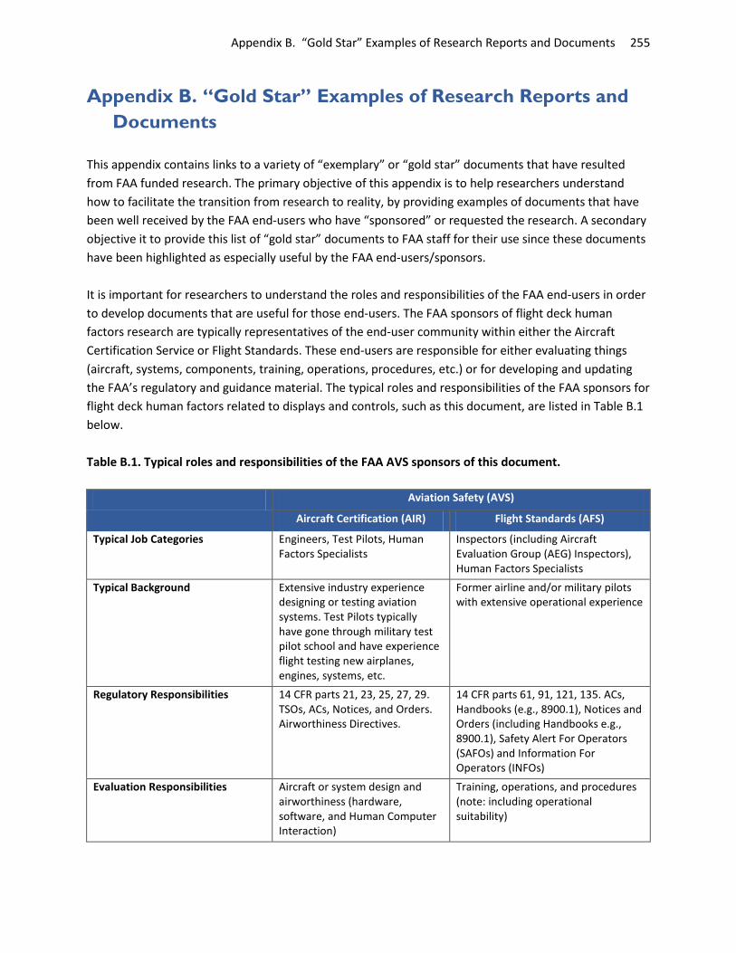
Appendix B. “Gold Star” Examples of Research Reports and Documents 255
Appendix B. “Gold Star” Examples of Research Reports and Documents
This appendix contains links to a variety of “exemplary” or “gold star” documents that have resulted from FAA funded research. The primary objective of this appendix is to help researchers understand how to facilitate the transition from research to reality, by providing examples of documents that have been well received by the FAA end-users who have “sponsored” or requested the research. A secondary objective it to provide this list of “gold star” documents to FAA staff for their use since these documents have been highlighted as especially useful by the FAA end-users/sponsors. It is important for researchers to understand the roles and responsibilities of the FAA end-users in order to develop documents that are useful for those end-users. The FAA sponsors of flight deck human factors research are typically representatives of the end-user community within either the Aircraft Certification Service or Flight Standards. These end-users are responsible for either evaluating things (aircraft, systems, components, training, operations, procedures, etc.) or for developing and updating the FAA’s regulatory and guidance material. The typical roles and responsibilities of the FAA sponsors for flight deck human factors related to displays and controls, such as this document, are listed in Table B.1 below. Table B.1. Typical roles and responsibilities of the FAA AVS sponsors of this document.
Aviation Safety (AVS)
Aircraft Certification (AIR) Flight Standards (AFS)
Typical Job Categories Engineers, Test Pilots, Human Factors Specialists
Inspectors (including Aircraft Evaluation Group (AEG) Inspectors), Human Factors Specialists
Typical Background Extensive industry experience designing or testing aviation systems. Test Pilots typically have gone through military test pilot school and have experience flight testing new airplanes, engines, systems, etc.
Former airline and/or military pilots with extensive operational experience
Regulatory Responsibilities 14 CFR parts 21, 23, 25, 27, 29. TSOs, ACs, Notices, and Orders. Airworthiness Directives.
14 CFR parts 61, 91, 121, 135. ACs, Handbooks (e.g., 8900.1), Notices and Orders (including Handbooks e.g., 8900.1), Safety Alert For Operators (SAFOs) and Information For Operators (INFOs)
Evaluation Responsibilities Aircraft or system design and airworthiness (hardware, software, and Human Computer Interaction)
Training, operations, and procedures (note: including operational suitability)

Appendix B. “Gold Star” Examples of Research Reports and Documents 256
For these types of FAA sponsors, successful reports will typically be aimed at either: 1) facilitating, streamlining, and standardizing some aspect of the evaluation process, or 2) identifying supplemental information to be included in the FAA’s regulatory and guidance documents. A key measure of success is if the research document is invoked by, incorporated into, or referenced by FAA regulatory and guidance material. Some key guidelines for developing useful documents to the FAA sponsors and end-users have been compiled in order to provide specifics in terms of what is useful vs. not useful. Specifically, FAA sponsors of the Flight Deck Human Factors research are typically looking for documents that are:
1. Directly supporting AVS sponsors who either: a) evaluate systems and/or operations/procedures, or b) develop and/or update FAA regulatory and guidance material.
2. Focused on developing FAA minimum requirements, not best practices. Note: FAA minimum requirements must be tied to a regulation or a TSO in order to be legally enforceable.
3. Focused on the identification and resolution of human factors issues. 4. Clearly distinguishing FAA regulatory and guidance material from non-FAA material. 5. Clearly making a tie to the FAA regulatory and guidance material. 6. Well formatted. Easy to skim and easily pick out key terms of interest. 7. Concise. Cut to the chase. No Ph.D. thesis or academic papers please! 8. Written in plain language for someone without a Ph.D. No jargon, no detailed discussion of
background, statistics, or research methods. Minimum use of acronyms and abbreviations. To illustrate some of the key guidelines, listed above, that make some documents “exemplary” in terms of useful content and format to the FAA Aviation Safety end-users, a set of “gold star” documents that have resulted from FAA flight deck human factors research funding are listed in the tables below. The documents are grouped into the following categories:
1. Checklists 2. Recommended Requirements and Guidelines 3. Industry Surveys and “Consumer Report” Type Documents 4. Research Reports and List of Documents
Checklists Checklists are typically designed to be used by FAA Test Pilots, Engineers, Human Factors Specialists or Inspectors during their review and evaluation of displays and controls. The checklists are intended to help standardize and systematize the evaluation process for the FAA staff in the field who conduct the “hands-on” evaluations of flight deck displays and controls that are submitted by avionics companies and airframe manufacturers for FAA approval. All of the checklists listed in the table below were developed with FAA research funding and are comprehensive in nature. In contrast, Appendix C contains checklists that were developed as very short, “quick reference” checklists to be used during flight test evaluations.

Appendix B. “Gold Star” Examples of Research Reports and Documents 257
In addition to the general characteristics listed above documenting what FAA sponsors are looking for in documents, characteristics of good checklists include:
• “Single source” documents that can be used as a “stand-alone” source for all human factors related issues, requirements, and recommendations for a given system
• Split out by the type of evaluation (e.g. “bench test” vs. “flight test”) • Have clear test scenarios and procedures • Have clear evaluation criteria • Clearly distinguish and reference “requirements” from “recommendations” • Clearly cites the source of each evaluation requirement and recommendation, so the FAA
evaluator can review the original text and or have additional context if the applicant wants to dispute the need for a given requirement/recommendation.
Checklist Information contained in the checklist
Reference/Link to the online checklist
1. Evaluating Compliance with AC 25-11A: Flight Deck Displays
This checklist is a list of human factors topics identified in AC 25-11A. It was intended to be a two page, high level reference for FAA st aff, who are very familiar with the contents of the AC, to remind them what to look for when evaluating flight deck displays and controls. Key strengths: Addresses all key human factors topics in AC 25-11A. Short and concise. Formatted to be easily readable at a glance. Applies to a wide range of flight deck displays and controls.
See Appendix C.2
2. Moving Map Requirements
This table contains a list of all requirements (“shalls”) from RTCA DO-257A, Minimum Operational Performance Standards for the Depiction of Navigational Information on Electronic Maps, which is invoked by TSO C-165. Key strengths: Contains all requirements from RTCA DO-257A. Concise and easy to read. Covers a wide range of human factors moving map topics for 1) plan view, 2) profile view, and 3) surface moving map displays. Format makes it easy to cross reference sections within the original RTCA document with notes, additional explanation, and also related recommendations.
Available for purchase from RTCA, Inc. http://www.rtca.org/

Appendix B. “Gold Star” Examples of Research Reports and Documents 258
Checklist Information contained in the checklist
Reference/Link to the online checklist
3. EFB Human Factors Design Review Checklist
This checklist provides a comprehensive list of specific human factors considerations for EFBs. The checklist was developed for FAA Aircraft Certification to facilitate the identification and resolution of human factors/pilot interface issues with EFB systems. This checklist may be useful in the early stages of development because it focuses on aspects of the design. Key strengths: Comprehensive. Well formatted so it can easily be skimmed to identify key topics without having to read the whole document. Clear distinction between requirements and recommendations. Designed to uncover specific design issues quickly. Also provides recommendations to FAA for new requirements.
EFB Human Factors Design Review Check
Chandra, D. C. and Yeh, M. (2006). A Tool Kit for Evaluating Electronic Flight Bags. (See Appendix A) http://ntl.bts.gov/lib/34000/34200/34294/DOT-VNTSC-FAA-06-21.pdf
4. EFB User-Interface Assessment Tool
This checklist contains a high-level list of human factors topics that may be applicable to EFBs. The checklist was develop for FAA Aircraft Certification, but may also be used by FAA Flight Standards Inspectors. This checklist may be used at any stage of the design and development process and even aid evaluations of line operations. Key strengths: Concise. Intended to be completed in a relatively short amount of time (e.g., one hour), but additional time may be helpful for data synthesis. Good for validating EFB features and functions.
EFB user Assessment Tool.doc
Chandra, D. C. and Yeh, M. (2006). A Tool Kit for Evaluating Electronic Flight Bags. (See Appendix B) http://ntl.bts.gov/lib/34000/34200/34294/DOT-VNTSC-FAA-06-21.pdf

Appendix B. “Gold Star” Examples of Research Reports and Documents 259
Checklist Information contained in the checklist
Reference/Link to the online checklist
5. GPS Aircraft Certification Checklist
This checklist provides a comprehensive list of human factors requirements and guidance for evaluating compliance to GPS TSO C-129 receivers including the controls, displays, and operating characteristics. This checklist was designed to be used by GPS manufacturers in advance of proposing a unit to the FAA, so they can test their own system, then the FAA Aircraft Certification Specialist(s) would come and use the same checklist to “spot check” compliance.
Key strengths: Small little book- easy to bring to evaluations. Structured scenarios, test points, and evaluation procedures. Bench and flight test sections. Clear and systematic evaluation of all key human factors requirements and recommendations. Clear distinction between requirements and recommendations. Easy reference to the original source documents for each requirement and recommendation. Easy to use format. Comprehensive. Clearly tailored for FAA AIR staff.
GPS Aircraft Certification Chkl.pdf
Huntley, M. S., Turner, J. W., Donovan, C. M., Madigan, E. (1995). FAA Aircraft Certification Human Factors and Operations Checklist for Standalone GPS Receivers (TSO C129 Class A). http://www.dtic.mil/cgi-bin/GetTRDoc?AD=ADA297073
6. GPS Flight Standards checklist
This document provides information for Flight Standards Aviation Safety Inspectors in evaluating GPS installations and operations. The document contains flow charts and checklists to streamline the process for performing approvals.
Key strengths: Small little book- easy to bring to evaluations. Structured scenarios, test points, and evaluation procedures. Bench and flight test sections. Clear and systematic evaluation of all key human factors requirements and recommendations. Clear distinction between requirements and recommendations. Easy reference to the original source documents for each requirement and recommendation. Easy to use format. Comprehensive. Clearly tailored for FAA AFS staff.
GPS_AFS_Chkl.pdf
Wright, M. (1996). Global Positioning System: A Guide for the Approval of GPS Receiver Installation and Operation. http://ntl.bts.gov/lib/33000/33600/33638/DOT-VNTSC-FAA-96-18.pdf

Appendix B. “Gold Star” Examples of Research Reports and Documents 260
Checklist Information contained in the checklist
Reference/Link to the online checklist
7. Multi-Function Displays: Human Factors Evaluation Guide
This document is intended to assist FAA Aircraft Certification specialists to identify human factors considerations for MFDs and controls. The checklists in this document may provide structure and a standardized approach for identifying and evaluating human factors aspects of the system. Key strengths: Small little book- easy to bring to evaluations. Structured scenarios, test points, and evaluation procedures. Bench and flight test sections. High level coverage applicable to a range of multi-function displays. Easy reference to the original source documents for each requirement and recommendation. Easy to use format.
MFD Human Factors Evaluation Guide.doc
Chamberlain, R. M., Heers, S. T., Mejdal, S., Delnegro, R. A., and Beringer, D. B. (2003). Multi-Function Displays: A Guide for Human Factors Evaluation. http://www.faa.gov/data_research/research/med_humanfacs/oamtechreports/2010s/media/201321.pdf
8. Airport Surface Moving Maps, ADS-B, Alerting
This checklist contains eight questions/considerations that are intended to assist Aircraft Certification staff when evaluating alerts. This checklist addresses all types of alerts, including warnings, cautions, and advisories, as well as indication messages and annunciations, however the focus is on alerts associated with ADS-B airport moving map runway incursion displays. Key strengths: Questions are concise. Explanatory information is provided, if needed. Applies to all types of alerts.
Airport Moving Maps, ADS-B, Alerting.docx
Not available online.
Recommended Requirements and Guidelines These are typically “single source” documents that can be used as a “stand-alone” source for all human factors related issues, requirements, and recommendations for a given system. They contain existing as well as suggestions for potential new FAA requirements and guidelines, based on empirical scientific and technical research data, that are intended to be folded directly into, or be invoked/referenced by, FAA regulatory and guidance documents such as Advisory Circulars, Technical Standard Orders, Handbooks, or Orders. For example, in the list below, the document type “EFB Guidelines” identifies key EFB human factors issues, compiles all of the FAA’s human factors related regulatory and guidance material for

Appendix B. “Gold Star” Examples of Research Reports and Documents 261
evaluating and approving EFBs, and makes recommendations for new FAA requirements and guidance material. The document has been widely acclaimed for helping the FAA field staff (in Aircraft Certification Offices and Flight Standards District Offices) evaluate the human factors aspects of a given system and also helps the policy staff identify gaps in their existing material that could potentially be filled by some of the research and/or industry recommendations. In addition to the general characteristics of good documents listed at the start of this appendix, characteristics of good requirements and guidelines documents include:
• “Single source” documents that can be used as a “stand-alone” source for all human factors related issues, requirements, and recommendations for a given system
• Clearly distinguish and reference “requirements” from “recommendations” • Clearly distinguish new proposed requirements and recommendations • Clearly cite the source of each evaluation requirement and recommendation, so the FAA
evaluator can review the original text and or have additional context if the applicant wants to dispute the need for a given requirement/recommendation.
Document Scope Information contained in the document
Reference/Link to the document
1. Flight Deck Displays and Controls
This report provides human factors principles and design guidelines for displays and controls that are generally applicable, even though the title implies that it only applies to GPS receivers and displays. Key strengths: Possibly THE best example of a comprehensive, yet concise report that summarizes all kinds of key information that is very valuable to the FAA Aircraft Certification staff to identify and resolve issues. Very comprehensive review of the literature, formatted into chapters and sub-chapters with easy to understand headings. Minimal “jargon.” Double boxes denote summary guidance, while text provides additional justification based on research data. Table of contents and outline is easy to skim to find key items without having to read the whole document.
Guidelines for the Design of GPS and LO
McAnulty, D. M. (1995). Guidelines for the Design of GPS and LORAN Receiver Controls and Displays. http://ntl.bts.gov/lib/33000/33500/33504/33504.pdf

Appendix B. “Gold Star” Examples of Research Reports and Documents 262
Document Scope Information contained in the document
Reference/Link to the document
2. General Flight Deck Human Factors
This report contains the scientific and technical background, with academic and research reference material, to support human performance guidelines to aid Aircraft Certification personnel for flight deck evaluations. The information in this report was developed from human factors seminars conducted for FAA Aircraft Certification personnel conducted in the early 90’s. Key strengths: Comprehensive. Very strong ties to research data. Lots of background information. One of original sources for key reference material like “primary field-of-view”.
HF for Flight Deck Cert. Personnel.pdf
Cardosi, K. and Huntley, M. S. (1993). Human Factors for Flight Deck Certification Personnel. http://ntl.bts.gov/lib/33000/33500/33543/33543.pdf
3. EFB This report identifies and prioritizes human factors guidance related to EFBs (e.g., how EFBs will be used by flightcrews, how EFBs will interact with other equipment, and what the implications for training and operating procedures may be). The report contains general information that can be applied to any EFB as well as specific guidance for electronic documents, electronic checklists, flight performance calculations, and electronic charts. The EFB Human Factors Design Review checklist (above) contains a summary of the requirements and recommendations in this document. Key strengths: Comprehensive and concise human factors report for EFBs. Well formatted so it can easily be skimmed to identify key topics without having to read the whole document. Guidance is prioritized into requirements, recommendations, suggestions, and design tradeoffs and clearly labeled as to whether it addresses hardware and software, pilot use/interaction, or training/procedures.
EFB HF Considerations.pdf
Chandra, D. C., Yeh, M., Riley, V., and Mangold, S. J. (2003). Human Factors Considerations in the Design and Evaluation of Electronic Flight Bags (EFBs). Version 2. http://ntl.bts.gov/lib/34000/34200/34292/DOT-VNTSC-FAA-03-07.pdf

Appendix B. “Gold Star” Examples of Research Reports and Documents 263
Document Scope Information contained in the document
Reference/Link to the document
4. Airport Surface Moving Maps, ADS-B, Alerting
This document identifies potential human factors considerations for displaying traffic information and runway status indications and alerts on an airport surface moving map. Key strengths: Clearly distinguishes FAA regulatory and guidance material from industry recommendations. Cites references and source documents. Clearly identifies what is known and where the research gaps are.
HF Guidance for Traffic Info and Alerts
Yeh, M. and Gabree, S. (2010). Human Factors Considerations for the Integration of Traffic Information and Alerts on an Airport Surface Map. http://ntl.bts.gov/lib/38000/38500/38543/DOT-VNTSC-FAA-10-16.pdf
Industry Surveys and “Consumer Report” Type Documents Industry survey documents provide a point-in-time snap-shot of the state of the industry in terms of what is currently on the market, what has been approved, and what is being prototyped by federally funded research labs for a particular type of system (e.g., GPS, moving maps). These documents are similar to “Consumer Reports” in that they identify products and functions that are currently on the market and describe features and functions for each system. These reports are intended to help FAA staff (in Aircraft Certification and Flight Standards) identify what systems, features, and functions have already been approved, so that they can focus their evaluations on new and novel systems, features, and functions that have not previously been approved. Providing information about which FAA offices have previously approved which systems helps FAA evaluators know who to call if they have questions about previously approved systems, features, and functions. In addition to the general characteristics of good documents listed at the start of this appendix, characteristics of good “industry surveys and consumer report” type documents include:
• Clearly identify who the manufacturers are and the products available • Provide images and examples of systems, features, and functions • Clearly identify what has been approved and by whom (which FAA office(s))

Appendix B. “Gold Star” Examples of Research Reports and Documents 264
Document Scope Avionics system/application addressed
Link to where the document can be found online
1. GPS This report documents the results of desk top and flight test evaluations of six GPS receivers conducted in June, 1997. The report provides a description of each of the GPS receivers and provides the scenario test and evaluation procedures used. Wright, M. C. (1998). Human Factors Evaluation of TSO-C129A GPS Receivers. http://ntl.bts.gov/lib/48000/48500/48577/Human_Factors_Evaluation_of_TSO-C129A_GPS_Receivers.pdf
2. Symbols for Navigation Aids, Airports, Lines, and Linear Patterns
This report documents symbols used for navigation aids, airports, lines, and linear patterns currently in use by nine avionics manufacturers and four chart providers. Yeh, M. and Chandra, D. C. (2008). Survey of Symbology for Aeronautical Charts and Electronic Displays: Navigation Aids, Airports, Lines, and Linear Patterns. http://ntl.bts.gov/lib/34000/34900/34909/DOT-VNTSC-FAA-08-01.pdf
3. EFBs This report provides an overview of EFB systems and capabilities as of June 2010, with focus on the human systems interface. Gabree, S., Yeh, M., and Jo, Y. J. (2010). Electronic Flight Bag (EFB): 2010 Industry Survey. http://ntl.bts.gov/lib/34000/34400/34493/EFB_2010_Industry_Survey.pdf
4. Airport Surface Moving Maps
This industry survey documents airport surface moving map products, as of March 2009.
Yeh, M. and Eon, D. (2009). Surface Moving Map Industry Survey. http://ntl.bts.gov/lib/34000/34900/34926/DOT-VNTSC-FAA-09-15.pdf
Research Reports and List of Documents FAA-funded research reports typically document the results of experimental research. They include sections about the purpose for the research, experimental methods and procedures, participants, results, and general conclusions. Research reports tailored to FAA end users are typically higher level documents than academic research reports because the FAA end-users typically have extensive aviation knowledge and expertise, but generally do not have a research methods or statistical background. As a result, the FAA end-users are not looking for the level of detail found in academic research reports. Most importantly, all statistical results reported should be explained in plain language for the FAA end-user audience. It is helpful to compile a list of all of the research documents from each research organization, as a way to inventory all the various research reports, checklists, and other documents. The list of documents should include files and report names and describe what is in each file or report, as well as the target audience, and anticipated use of the information.

Appendix B. “Gold Star” Examples of Research Reports and Documents 265
In addition to the general characteristics of good documents listed at the start of this appendix, characteristics of good research reports include:
• Easily understandable by an audience without an experimental research or statistics background • Clearly describe/interpret all statistical results in plain language • Formulas and algorithms (etc.) should primarily be in appendices, not in the body of the
document • Clearly identify recommendations for new FAA requirements vs. best practices, based on
research results
Document Scope Information Contained in the Document
Link to where the document can be found online
1. ADS-B Symbology - the Usefulness of the Proximate Status Indication
This report describes a research study that examined the value of the proximate status indication as represented by symbol fill for Cockpit Displays of Traffic Information (CDTIs),
Zuschlag, M., Chandra, D. C., Grayhem, R. (2013). The Usefulness of the Proximate Status Indication as Represented by Symbol Fill on Cockpit Displays of Traffic Information. http://ntl.bts.gov/lib/47000/47600/47675/DOT-VNTSC-FAA-13-03.pdf
2. List of Documents This is a sample summary list of a large number of research documents. Each item in the list contains the name of the document, a short descriptions of what is contained in the document and the intended end-users. This list was put together by the US DOT Volpe Center to compile the research reports, conference papers, and deliverables funded by the Human Factors Division in support of the Office of Aircraft Certification. This type of document is especially helpful for FAA staff sort through hundreds of research and regulatory documents find what they are looking for.
List of Documents.doc

This page left blank intentionally.

Appendix C. Quick Reference Flight Test Checklists, Evaluation Procedures, and Scenarios 267
Appendix C. Quick Reference Flight Test Checklists, Evaluation Procedures, and Scenarios
This appendix contains eight tools that are intended to assist the Aircraft Certification flight test pilot or engineer in identifying human factors considerations during a display evaluation. All of the tools are short and concise and are intended to be used as a “quick reference” during FAA flight test evaluations. (This is in contrast to the checklists in Appendix B which are more in-depth and comprehensive.) The table below documents the various checklists, evaluation procedures, and scenarios. The first six tools were developed with research funding from the FAA in conjunction with the end-users/sponsors, including FAA Flight Test Pilots. The last two tools in this appendix contain evaluation procedures that were developed directly by an FAA Flight Test Pilots and an FAA Human Factors Specialist/Flight Test Engineer.
Title Document Scope
C.1 Steps for Conducting Evaluations
This appendix summarizes the steps for conducting a usability evaluation; these steps may be useful for FAA evaluators and manufacturers interested in conducting their own evaluations.
C.2 Evaluating Compliance with AC 25-11A: Flight Deck Displays
This checklist is a list of human factors topics identified in AC 25-11A. It is intended to be a two page, high level reference that serves as a reminder of what to look for when evaluating flight deck displays and controls.
C.3 Generic Procedures, Scenarios, and Considerations for Evaluating Displays and Controls
This appendix contains general tasks that are intended to apply to any flight deck display or control.
C.5 Weather Display Evaluation Procedures
This appendix contains procedures that may be useful for evaluating weather displays. The procedures were developed researchers at Kansas State University.
C.6 GPS Evaluation Procedures and Scenarios
This appendix contains procedures that may be useful for evaluating GPS displays. The procedures were developed by Steve Huntley (US DOT Volpe Center).
C.4 GPS/Moving Map Evaluation Procedures
This appendix provides procedures that may be useful for evaluating GPS displays. The procedures were developed by Mike White (FAA).
C.7 EVS/SVS Evaluation Procedures This appendix contains tasks that may be useful for evaluating EVS/SVS displays. The procedures were developed by Jeff Holland (FAA).

C.1. Steps for Conducting Evaluations 268
C.1. Steps for Conducting Evaluations This checklist summarizes steps for conducting a display or control evaluation. These steps are intended for FAA evaluators or manufacturers interested in conducting their own evaluations. 1. Review the user interface.
• Obtain an understanding of the functions that are available • Obtain an understanding of how the functions are accessed, e.g., using a workflow diagram that
describes the different steps and sequences to accomplish a task
2. Select the evaluation methodology. • A physical mock-up of the flight deck or display system may be used early in the display design,
e.g., to address anthropometric considerations such as the reach and visibility of the display. • Part-task evaluations that emulate display capabilities for a single system or a group of systems
can be used to identify usability issues, e.g., in an office setting. Note that the results of these part-task evaluations may be somewhat limited because tasks are being performed in isolation.
• Simulator evaluations offer the opportunity to collect feedback through a high-fidelity integrated emulation of the flight deck and operational environment, but the results may be limited by the extent to which the simulator is able to accurately capture the operating environment.
• In-flight evaluations may be needed in some cases.
3. Specify tasks. • Identify the tasks that the user will try to accomplish with the display. • Tasks should not be over-specified (e.g., by providing step-by-step instructions for accomplishing
a function). • Sample tasks/scenarios are provided in Sections C.3 - C.7.
4. Recruit participants for the evaluation.
• Recruit participants who are not too familiar with the display design, so that they can evaluate the user interface from the point of view of a new user.
• Ideally, participants evaluating the display should be representative of the target end users, e.g., select pilots who have a similar range of experience and ratings as those that are expected to use the final display. However, participants who are not pilots may also be able to provide valuable input for some types of evaluations.
5. Conduct the evaluation. • Provide participants with some initial training that provides information on the intended
function of the display and so that they can become familiar with the functions available. • Have participants complete tasks similar to what the target end user would do.

C.1. Steps for Conducting Evaluations 269
• Collect measures of performance, such as the time to complete a task, the number of steps used to complete a task, and the accuracy with which the task was completed.
6. Document what was done (and what was not done). The evaluation method, assumptions, and results should be documented. Documentation of potential issues identified during the evaluation is also helpful. The documentation should include the following:
• Description of the current design or configuration, including software version number. This is detailed information on how the functions under review work. This is essential for future evaluations, since the system may change since the original evaluation. It is also important to document what version or configuration control was evaluated.
• What, if any, evaluations were conducted • Problem statement describing the potential issue(s) • Pertinent regulatory references and guidance (e.g., the applicable 14 CFR, part requirement) • List of participants/observers (e.g., who was in the room?)
Any potential issues identified during the evaluation should be included and documented in such a way that they are clear, accurate, and easily understood. This documentation minimizes the potential for misunderstandings by documenting key assumptions, evaluation procedures, and results.

C.2. Evaluating Compliance with AC 25-11A: Flight Deck Displays 270
C.2. Evaluating Compliance with AC 25-11A: Flight Deck Displays
This following checklist provides a list of human factors topics to consider during a display system evaluation. The topics are applicable to all display systems and controls. More information about each topic can be found in the body of this document. The design of the checklist and the wording of the items originated from research conducted to develop the Electronic Flight Bag (EFB) User-Interface Assessment Tool (see Chandra and Yeh (2006) for more information). That tool was then adapted to serve as a companion to AC 25-11A.
The display system and/or control should be evaluated with respect to each topic in this checklist. Comments about each item should be provided with supporting examples. It is important to note that comments can be positive, highlighting the good aspects of a display system’s design.
DISPLAY CHARACTERISTICS • Size and resolution • Luminance, contrast ratio • Gray scale, chromaticity • Glare, reflections • Defects • Dynamics (refresh rate, update rate and
response time) • Lighting Issues (day vs. night use)
Brightness adjustment (automatic or manual) • Mechanical integrity, durability • Installation
Visual obstructions, cross-flight-deck viewing Viewability and viewing envelope Interaction/interference with other flight
deck systems
DISPLAY INFORMATION ELEMENTS Text • Size, font style, case, spacing, color, contrast,
illumination • Clarity and consistency of terms and abbreviations Symbols, Graphical Depictions and Images • Clarity of intended meaning, confusability,
consistency with other flight deck displays • Position accuracy • Number, legibility and distinctiveness • Image size, resolution and line width • Color and luminance • Orientation, ownship directionality • Zooming and panning Display Indications, Annunciations, Messages and Alerts • Ease and accuracy of interpretation
Data accuracy, trend depiction Filtering characteristics, depiction of
operating range, delimiters Visual clutter, arrangement of information,
frame of reference Use of color (especially red and
amber/yellow) and color-coding Intensity (aural or visual)
Sharing Information on the Display (Multiple Applications) • Managing shared displays (overlays, time-sharing,
concurrent displays in separate windows) Smooth transitions between displays Accuracy of motion (e.g., position, time) Readability Information prioritization, blending De-cluttering
• Consistency across shared information displays (e.g., symbols/colors, orientation, data range)
• Ease of movement between and within pages Accessing functions, options, and specific
information/pages Identifying the current page

C.2. Evaluating Compliance with AC 25-11A: Flight Deck Displays 271
ORGANIZATION AND MANAGEMENT OF INFORMATION ELEMENTS
Formatting/Layout • Arrangement of information on the display
Page format, structure and organization (e.g., “Basic T”)
Consistent positioning or relative positioning of information on the display
Consistency with other flight deck displays • Consistency with user expectations and internal
logic • Indication of active regions (controls) and off-
screen material • Labels (e.g., for menus, scales, modes, and units)
Intuitiveness, location, orientation Managing Display Information • Display configuration and re-configuration • Managing windows and menus • Number of inputs to complete a task • Intuitive logic and menu structure, e.g., number of
steps • Use of automatic pop-ups • System responsiveness
CONTROLS (e.g., cursor control device, touch screens, and physical knobs)
• Accessibility • Labels: Illumination • Choice and operating characteristics of
mechanism (e.g., latency and gain) • Use under normal range of environmental
conditions (e.g., turbulence, normal vibration, bright light)
• Audio and tactile characteristics
DESIGN PHILOSOPHIES • General flight deck philosophy
Compatibility with other displays and controls Consistency of controls and display elements
across flight deck displays • Color Philosophy
Consistency, number of colors, discriminability of colors, use of red and amber/yellow
• Information Management Philosophy Conventions for information location
• Interactivity Philosophy Amount of feedback (system state, alerts,
confirmations, messages and prompts, modes, etc.)
Clarity and consistency of annunciations, indicators, messages
• Redundancy Management Philosophy Accommodation for single and multiple
failures
WORKLOAD • Problem areas (excessive concentration, fatigue)
ERROR HANDLING AND PREVENTION • Training time, learning curve • System feedback (system state, alerts, modes,
etc.) • Recovery from errors (e.g., cancel, clear, undo) • Susceptibility to error (mode errors, selection
errors, data entry errors, reading errors, etc.) • Error messages
AUTOMATION • Is automation (e.g., automatic pop-ups) disruptive
or supportive? Predictable? • User control over automation? (e.g., manual
override)
FAILURE PROTECTION AND MITIGATION • Failure containment • Failure notification and identification

C.3. Generic Procedures, Scenarios, and Considerations for Evaluating Displays and Controls 272
C.3. Generic Procedures, Scenarios, and Considerations for Evaluating Displays and Controls
This appendix contains a set of general procedures and scenarios that can be used for flight deck display and control evaluations. These procedures, scenarios, and considerations were developed by Divya Chandra and Michelle Yeh at the US DOT Volpe Center in their research effort to develop EFB evaluation tools for Aircraft Certification staff. The format and layout for this tool was based on that developed in previous GPS display evaluation research (see Appendix C.5 GPS Evaluation Procedures and Scenarios). Tables are provided below that contain procedures, scenarios, and considerations for various human factors topic areas. The topic area is listed in the shaded gray box at the top of each table. For each topic area, a human factors objective/issue is identified and procedures for evaluating the issue are provided. Some evaluation considerations for meeting the primary objective are also included. Display Hardware Objectives
Ensure that the display is readable under a wide range of lighting conditions.
Evaluation Procedure
1. Examine the display hardware. This includes the physical form factor and the display quality. • Evaluate the display placement and visibility • Consider its resolution, brightness, off-axis readability, etc.
2. Examine the display under the following conditions: (a) Dark room (night-time operations), (b) Direct sunlight (day-time operations), and (c) Office lighting. In each of these conditions: • Try adjusting the screen brightness. • View the display at off-axis angles to ensure readability
Evaluation Considerations • Is the display acceptable for the intended applications?
Do artifacts appear on the display (e.g., ghost images or lines, jagged lines, or fuzzy images)? • Is the display readable under the range of flight deck lighting conditions? • Is the screen brightness or contrast adjustable?
Observations and Comments

C.3. Generic Procedures, Scenarios, and Considerations for Evaluating Displays and Controls 273
Controls Objectives
Ensure that all controls are accessible and appropriately placed. Ensure that the intended functions of all controls are clear.
Evaluation Procedure 1. Evaluate the placement, visibility, and accessibility of the controls. 2. Operate all controls according to the intended use.
Evaluation Considerations • Are all the controls accessible? • Are all the controls visible? • Are the controls located so that the pilot can access and use each control without interference? • Do any controls require significant or sustained muscular exertion? • Do any controls require precision to operate (e.g., cursor control devices, touch screens, etc.)? • Can any of the controls be activated inadvertently?
For example, if a key is held down for a long time, is the input processed correctly? • Are controls labeled consistently for their intended function?
Observations and Comments
Display Installation Objectives
Ensure that the display has been installed in a way that does not interfere with task performance while remaining robust to the physical demands of the flight deck environment (e.g. vibration).
Evaluation Procedure 1. Evaluate the placement and accessibility of the display. 2. Examine the connections and mounting of the display.
Evaluation Considerations • Are hardware components that are routinely used easy to access?
If not, is there any impact on flight task performance or safety? • Are the hardware components robust enough for use in the flight environment?
For example, will connectors stay in place after lengthy use in a vibrating environment or will a stylus remain functional?
• Is the display located so that it can be accessed easily, particularly during high workload phases of flight?
Observations and Comments
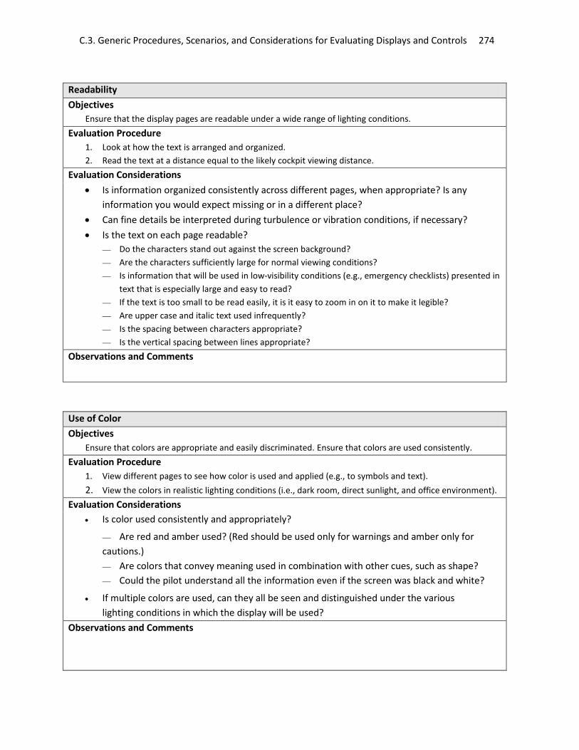
C.3. Generic Procedures, Scenarios, and Considerations for Evaluating Displays and Controls 274
Readability Objectives
Ensure that the display pages are readable under a wide range of lighting conditions. Evaluation Procedure
1. Look at how the text is arranged and organized. 2. Read the text at a distance equal to the likely cockpit viewing distance.
Evaluation Considerations • Is information organized consistently across different pages, when appropriate? Is any
information you would expect missing or in a different place? • Can fine details be interpreted during turbulence or vibration conditions, if necessary? • Is the text on each page readable?
Do the characters stand out against the screen background? Are the characters sufficiently large for normal viewing conditions? Is information that will be used in low-visibility conditions (e.g., emergency checklists) presented in
text that is especially large and easy to read? If the text is too small to be read easily, it is it easy to zoom in on it to make it legible? Are upper case and italic text used infrequently? Is the spacing between characters appropriate? Is the vertical spacing between lines appropriate?
Observations and Comments
Use of Color Objectives
Ensure that colors are appropriate and easily discriminated. Ensure that colors are used consistently. Evaluation Procedure
1. View different pages to see how color is used and applied (e.g., to symbols and text). 2. View the colors in realistic lighting conditions (i.e., dark room, direct sunlight, and office environment).
Evaluation Considerations • Is color used consistently and appropriately?
Are red and amber used? (Red should be used only for warnings and amber only for cautions.) Are colors that convey meaning used in combination with other cues, such as shape? Could the pilot understand all the information even if the screen was black and white?
• If multiple colors are used, can they all be seen and distinguished under the various lighting conditions in which the display will be used?
Observations and Comments
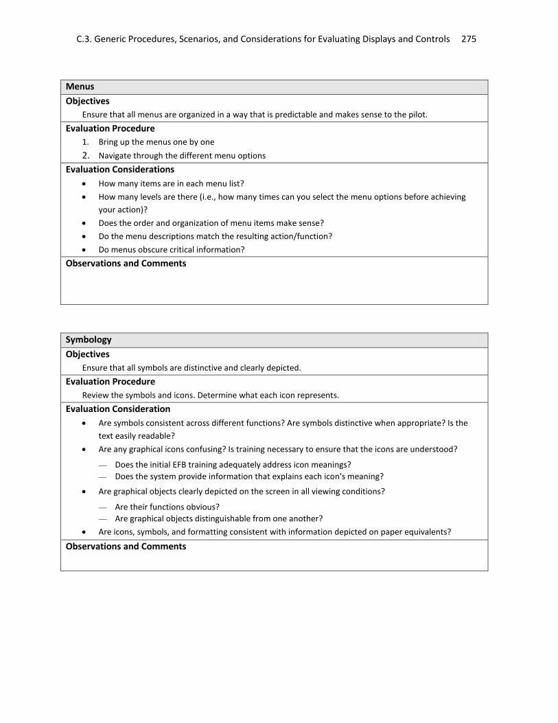
C.3. Generic Procedures, Scenarios, and Considerations for Evaluating Displays and Controls 275
Menus Objectives
Ensure that all menus are organized in a way that is predictable and makes sense to the pilot. Evaluation Procedure
1. Bring up the menus one by one 2. Navigate through the different menu options
Evaluation Considerations • How many items are in each menu list? • How many levels are there (i.e., how many times can you select the menu options before achieving
your action)? • Does the order and organization of menu items make sense? • Do the menu descriptions match the resulting action/function? • Do menus obscure critical information?
Observations and Comments
Symbology Objectives
Ensure that all symbols are distinctive and clearly depicted. Evaluation Procedure
Review the symbols and icons. Determine what each icon represents. Evaluation Consideration
• Are symbols consistent across different functions? Are symbols distinctive when appropriate? Is the text easily readable?
• Are any graphical icons confusing? Is training necessary to ensure that the icons are understood?
Does the initial EFB training adequately address icon meanings? Does the system provide information that explains each icon's meaning?
• Are graphical objects clearly depicted on the screen in all viewing conditions?
Are their functions obvious? Are graphical objects distinguishable from one another?
• Are icons, symbols, and formatting consistent with information depicted on paper equivalents?
Observations and Comments

C.3. Generic Procedures, Scenarios, and Considerations for Evaluating Displays and Controls 276
Messages, Annunciations, and Alerts Objectives
Ensure that messages, annunciations, and alerts are clearly visible and attract an appropriate amount of attention from the user.
Evaluation Procedure 1. If the display has different modes, select each mode. 2. Activate all alerts and warnings.
• See how colors are used. • Compare the presentation of alerts and warnings with that of other flight deck systems. • View the message prioritization scheme.
3. Review the alerting scheme. Evaluation Considerations
• Are mode changes clearly annunciated? • Are the terms used meaningful? • Are abbreviations used consistently with recommended practice? • For installed systems, do alerts and reminders meet the requirements in the appropriate
regulations (specifically §§ 23.1322 or 25.1322)? • Is there an overall scheme for generating alerts/reminders (e.g., when will they appear, how are
they prioritized)? Is it adequate/appropriate? • Are distracting flashing symbols avoided? • Are messages inhibited during high workload phases of flight unless they pertain to the failure or
degradation of the current application? Observations and Comments
System Responsiveness Objectives
Ensure that the system is responsive enough user input that it does not impair performance. Evaluation Procedure
Evaluate the responsiveness of the system by: • Enter alphanumeric data. See how quickly the characters are shown on the screen. • If there is a cursor control device, move the cursor to see whether its location on the screen is
updated. • Select an action from a button.
Evaluation Considerations • Does the system respond immediately to user inputs, e.g., by providing feedback?
If the processing is delayed, are busy indicators and/or progress indicators displayed? Are the indicators clear and useful to the pilot?
• Does the system processing ever slow down to the point where normal use is impaired? Observations and Comments

C.3. Generic Procedures, Scenarios, and Considerations for Evaluating Displays and Controls 277
Failure Mitigation
Objectives Ensure that the failure of one system does not lead the failure of subsequent systems.
Evaluation Procedure 1. Note the content, duration, intensity, and prioritization of alerts. 2. Determine how the system responds to emergency situations, function failures and non-display system
failures. 3. Review the safety analysis document to identify the means of mitigation.
Evaluation Considerations
• What means of mitigation have been used to prevent system failures? • Are the means of mitigation sufficient? Is a backup provided in the case of a failure? • Is an indication of display failure provided? • Do non-display failures affect the proper use of display features?
Observations and Comments
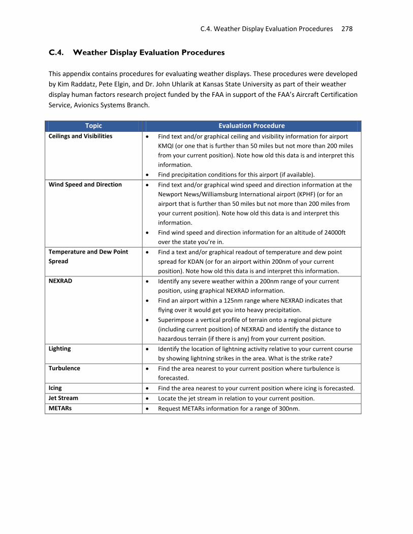
C.4. Weather Display Evaluation Procedures 278
C.4. Weather Display Evaluation Procedures This appendix contains procedures for evaluating weather displays. These procedures were developed by Kim Raddatz, Pete Elgin, and Dr. John Uhlarik at Kansas State University as part of their weather display human factors research project funded by the FAA in support of the FAA’s Aircraft Certification Service, Avionics Systems Branch.
Topic Evaluation Procedure Ceilings and Visibilities • Find text and/or graphical ceiling and visibility information for airport
KMQI (or one that is further than 50 miles but not more than 200 miles from your current position). Note how old this data is and interpret this information.
• Find precipitation conditions for this airport (if available). Wind Speed and Direction • Find text and/or graphical wind speed and direction information at the
Newport News/Williamsburg International airport (KPHF) (or for an airport that is further than 50 miles but not more than 200 miles from your current position). Note how old this data is and interpret this information.
• Find wind speed and direction information for an altitude of 24000ft over the state you’re in.
Temperature and Dew Point Spread
• Find a text and/or graphical readout of temperature and dew point spread for KDAN (or for an airport within 200nm of your current position). Note how old this data is and interpret this information.
NEXRAD • Identify any severe weather within a 200nm range of your current position, using graphical NEXRAD information.
• Find an airport within a 125nm range where NEXRAD indicates that flying over it would get you into heavy precipitation.
• Superimpose a vertical profile of terrain onto a regional picture (including current position) of NEXRAD and identify the distance to hazardous terrain (if there is any) from your current position.
Lighting • Identify the location of lightning activity relative to your current course by showing lightning strikes in the area. What is the strike rate?
Turbulence • Find the area nearest to your current position where turbulence is forecasted.
Icing • Find the area nearest to your current position where icing is forecasted. Jet Stream • Locate the jet stream in relation to your current position. METARs • Request METARs information for a range of 300nm.

C.5. GPS Evaluation Procedures and Scenarios 279
C.5. GPS Evaluation Procedures and Scenarios This appendix contains evaluation procedures and scenarios for identifying human factors/pilot interface aspects of Global Positioning Systems (GPS) displays and controls. The procedures and scenarios were developed by Dr. Steve Huntley at the US DOT Volpe Center as part of a GPS evaluation research program, funded by the FAA in support of the FAA’s Aviation Safety Organization. Demonstrate how to fly a full approach and a missed approach Evaluation Procedure
Program the GPS Unit: 1. Destination and intermediate waypoints 2. Select approach 3. Select IAF
Prior to reaching the FAF: 4. Switch from SEQ to HOLD (in order to fly the procedure turn) 5. Switch to SEQ when established inbound
At map: 6. Execute DIRECT/ENTER to call up missed approach
Evaluation Considerations • Location of GPS unit and annunciator buttons • Number of control actions necessary to program an approach • Ability to confirm route before activating • Automatic waypoint sequencing
• Arming &request for altimeter input • When receiver is switched from SEQ to HOLD prior to reaching the FAF the receiver provides distance and
bearing form the FAF for guidance
• When passing MAP guidance is provided by bearing and distance from MAP until DIRECT/ENTER is programmed for guidance for MAHP (Missed Approach Hold Point)
Demonstrate programming to repeat the approach, and improper use of the HOLD mode Evaluation Procedure
Program the GPS unit: 1. Go to ROUTE page that shows the active route 2. Select desired waypoint (FAF) 3. Switch from SEQ to HOLD after passing the FAF
Evaluation Considerations • There is no bearing and distance from the FAF for guidance • The leg sequences from the FAF inbound when passing the FAF outbound

C.5. GPS Evaluation Procedures and Scenarios 280
Demonstrate how one GPS receiver might handle flying a DME arc and the ramifications for terrain clearance Evaluation Procedure
Program the GPS unit: 1. Call up the desired approach 2. Arm the approach 3. Set the proper altimeter in the GPS
Fly to: 4. Intercept the arc from outside the first waypoint 5. Fly the arc as directed by the GPS receiver
Evaluation Considerations If flown in the manner of a normal GPS approach, the following will occur:
• The GPS flies direct from waypoint to waypoint. The GPS does not describe an arc. • If the arc is designed to promote terrain clearance, it will not be provided. • In most cases there is no means of reference to the distance from the runway end waypoint for
guidance in flying the arc. Therefore, the pilot is not able to use “piloting techniques similar to those applicable to use of the reference DME facility” (TSO-C129)
Demonstrate the workload associated with flying a multi-segmented course reversal as a part of an approach Evaluation Procedure
Program the GPS unit: 1. Call up the desired approach 2. Arm the approach 3. Set the proper altimeter in the GPS
Fly to: 4. Intercept the course line between waypoints F121D and F057N 5. Begin the course reversal at waypoint F054Q
Evaluation Considerations • When flying at 170 KIAS, the pilot has 26.5 seconds between the waypoints of each 1.25 nm segment • Pilot actions must include the following:
1. Monitor the GPS receiver for waypoint passage and upcoming waypoint designation 2. Check the approach plate to corroborate waypoint designation and next course to fly 3. Set the HSI OBS needle to the correct courses 4. Accomplish the descent and speed reduction, if necessary 5. Fly the airplane
• The original TRAML FMS procedure did not provide compass courses for the course reversal. Those were provided by the VOLPE Center to enable flying the procedure (we couldn’t have flown it without course guidance)
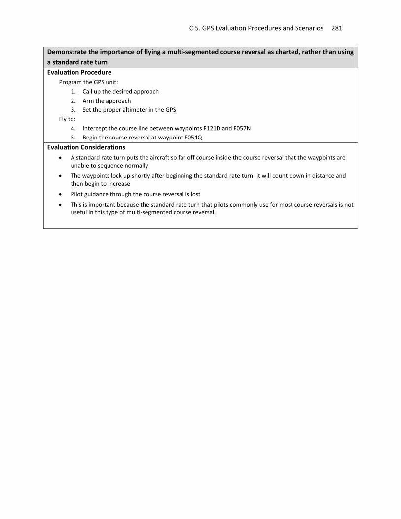
C.5. GPS Evaluation Procedures and Scenarios 281
Demonstrate the importance of flying a multi-segmented course reversal as charted, rather than using a standard rate turn Evaluation Procedure
Program the GPS unit: 1. Call up the desired approach 2. Arm the approach 3. Set the proper altimeter in the GPS
Fly to: 4. Intercept the course line between waypoints F121D and F057N 5. Begin the course reversal at waypoint F054Q
Evaluation Considerations • A standard rate turn puts the aircraft so far off course inside the course reversal that the waypoints are
unable to sequence normally
• The waypoints lock up shortly after beginning the standard rate turn- it will count down in distance and then begin to increase
• Pilot guidance through the course reversal is lost • This is important because the standard rate turn that pilots commonly use for most course reversals is not
useful in this type of multi-segmented course reversal.

C.6 GPS/Moving Map Evaluation Procedures 282
C.6. GPS/Moving Map Evaluation Procedures This checklist provides a set of procedures for evaluating moving map displays. This checklist was developed by former FAA Test Pilot, Mike White, who used these procedures in his moving map display evaluations. Task 1: Pre-taxi Please do the following: Assume you are about to start the engine
• Pull up the Engine Start Checklist (actual checklist not available) • Turn on the rotating beacon • Pull up the Engine Synoptic page
Prior to taxiing, do the following:
• Collect ATIS information by setting Com2 Active to 126.3’ • Increase Com2 Volume • Turn Com2 squelch OFF
Assume you have listened to ATIS
• Adjust Baro setting to 30.01 inHg • Set Com2 Active to Tower 120.9 (use pick list) • Set Com1 Standby to Departure 134.5 • Set Transponder to 5267 Standby • Set Com2 Active to Ground 121.7 (use pick list) • Set Vloc1 Active to Vero Beach VOR (117.3) • Select CDI source to GPS • Select Density Altitude display on airspeed tape
Prior to takeoff
• Select Recognition, Nav and Strobe lights ON • Select ALT on transponder
Task 2: After Take-Off Upon departure you are instructed to turn left to a heading of 330 and contact departure on 134.5
• Set Heading Bug • Flip Com1 to Departure Frequency • Set Altitude bug to 8500 ft • Change Course to match Heading Bug • Hide Bearing Pointer 2 • Set Bearing Pointer 1 source to ADF1
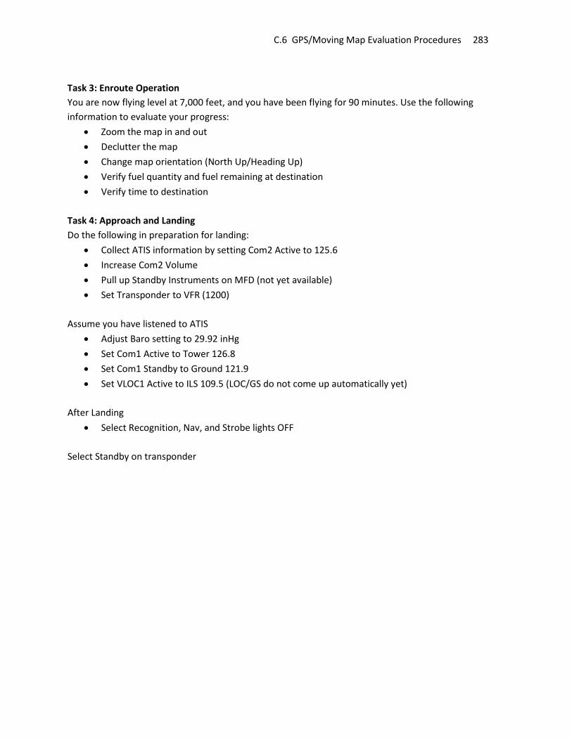
C.6 GPS/Moving Map Evaluation Procedures 283
Task 3: Enroute Operation You are now flying level at 7,000 feet, and you have been flying for 90 minutes. Use the following information to evaluate your progress:
• Zoom the map in and out • Declutter the map • Change map orientation (North Up/Heading Up) • Verify fuel quantity and fuel remaining at destination • Verify time to destination
Task 4: Approach and Landing Do the following in preparation for landing:
• Collect ATIS information by setting Com2 Active to 125.6 • Increase Com2 Volume • Pull up Standby Instruments on MFD (not yet available) • Set Transponder to VFR (1200)
Assume you have listened to ATIS
• Adjust Baro setting to 29.92 inHg • Set Com1 Active to Tower 126.8 • Set Com1 Standby to Ground 121.9 • Set VLOC1 Active to ILS 109.5 (LOC/GS do not come up automatically yet)
After Landing
• Select Recognition, Nav, and Strobe lights OFF Select Standby on transponder
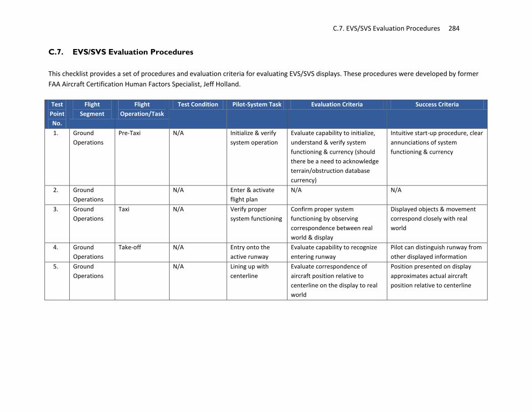
C.7. EVS/SVS Evaluation Procedures 284
C.7. EVS/SVS Evaluation Procedures
This checklist provides a set of procedures and evaluation criteria for evaluating EVS/SVS displays. These procedures were developed by former FAA Aircraft Certification Human Factors Specialist, Jeff Holland.
Test
Point No.
Flight Segment
Flight Operation/Task
Test Condition Pilot-System Task Evaluation Criteria Success Criteria
1. Ground Operations
Pre-Taxi N/A Initialize & verify system operation
Evaluate capability to initialize, understand & verify system functioning & currency (should there be a need to acknowledge terrain/obstruction database currency)
Intuitive start-up procedure, clear annunciations of system functioning & currency
2. Ground Operations
N/A Enter & activate flight plan
N/A N/A
3. Ground Operations
Taxi N/A Verify proper system functioning
Confirm proper system functioning by observing correspondence between real world & display
Displayed objects & movement correspond closely with real world
4. Ground Operations
Take-off N/A Entry onto the active runway
Evaluate capability to recognize entering runway
Pilot can distinguish runway from other displayed information
5. Ground Operations
N/A Lining up with centerline
Evaluate correspondence of aircraft position relative to centerline on the display to real world
Position presented on display approximates actual aircraft position relative to centerline

C.7. EVS/SVS Evaluation Procedures 285
Test Point No.
Flight Segment
Flight Operation/Task
Test Condition Pilot-System Task Evaluation Criteria Success Criteria
6. Ground Operations
N/A Maintenance of aircraft along centerline during take-off roll
1. Evaluate correspondence of aircraft position relative to centerline on the display to real world throughout take-off 2. Evaluate display dynamics, movement & jitter throughout take-off roll
1. Position presented on display approximates actual aircraft position relative to centerline throughout take-off 2. Dynamics, movement & jitter does not unduly distract pilot
7. Ground Operations
N/A Runway distance remaining
Evaluate capability to determine runway distance remaining with reference to PFD presentation alone
Display does not mislead to believe more runway is left than actual
8. Climb-out Initial climb attitude
Pathway, traffic, terrain selected for display without F/D present. Pilot to don vision restriction device & continue use throughout the flight
Establishment & maintenance of best rate of climb
Evaluate capability to capture & maintain appropriate climb attitude for best rate
a. Appropriate climb attitude information on PFD is clear, obvious and correctly corresponds to real world attitude. b. Other symbology does not interfere with observation of primary flight information
9. Enroute Departure vectors
ATC or test conductor will give pilot initial heading to fly, then change it to another heading
Follow ATC headings (vectors) guidance
Evaluate guidance & cues on ADI to fly headings
Heading information is clear & obvious, enabling the pilot to capture & maintain specified headings

C.7. EVS/SVS Evaluation Procedures 286
Test Point No.
Flight Segment
Flight Operation/Task
Test Condition Pilot-System Task Evaluation Criteria Success Criteria
10. Enroute Join planned route
ATC or test conductor will clear aircraft to a subsequent waypoint on flight plan, skipping the most immediate waypoint
Recognize and take action to join planned route (Based on PFD symbology only)
1. Evaluate capability to determine location, direction of and distance to pathway based on PFD presentation alone at an angle 45-90 degrees from current heading. 2. Evaluate for interference with other displayed symbology
1. Pilot is correctly determines location, direction of and approximate distance to pathway. Pilot maneuvers aircraft to join pathway at desire point and direction. 2. Does not interfere with the visibility, reading, interpretation of other displayed symbology
11. Enroute Join planned route
Subsequent waypoint has MCA above which the aircraft can achieve before crossing waypoint (primarily using pathway guidance)
Take action to climb to MCA for next waypoint along route
1. Evaluate capability to recognize aircraft will not be at MCA altitude at point of intersection. 2. Evaluate effect of pathway presented overhead (higher than aircraft) on pilot performance.
1. Pilot recognizes aircraft will not be at pathway altitude & continues, understanding aircraft will need to continue climb under pathway. 2a. Pilot is not compelled to increase climb rate above best rate of climb to capture pathway. 2b. Pathway provides acceptable horizontal & vertical guidance along planned route.
12. Enroute Flight along course without F/D presented
Maintenance of straight & level flight (primarily using pathway guidance) at designated altitude & course
Maintain direction & altitude along desired course to next waypoint
Evaluate effectiveness & usability of pathway
a. Pathway display provides acceptable guidance for navigation between waypoints at acceptable workload levels b. Pathway does not detract from other symbology & information presented on the PFD

C.7. EVS/SVS Evaluation Procedures 287
Test Point No.
Flight Segment
Flight Operation/Task
Test Condition Pilot-System Task Evaluation Criteria Success Criteria
13. Enroute Flight along course without F/D presented
Performance of turns while descending to lower altitude
Maintain aircraft along pathway
Evaluate effectiveness & usability of pathway for turning flight
a. Pathway display provides acceptable guidance for navigation along curve paths at acceptable workload levels b. Pathway does not detract from other symbology & information presented on the PFD
14. Enroute Flight along course with F/D presented
Maintenance of straight & level flight (primarily using pathway guidance) at designated altitude & course
Maintain direction & altitude along desired course to next waypoint
1. Evaluate effectiveness & workload of pathway & F/D for enroute straight path navigation 2. Evaluate correspondence & usability of pathway & F/D guidance together 3. Evaluate displayed symbology for clutter, symbol/scene occlusion & interference
1. Pathway & F/D guidance provide acceptable guidance for navigation along straight paths at acceptable workload levels 2. Pathway & F/D guidance correspond well and provide for acceptable usability when presented & used together 3. Display does not appear cluttered nor does displayed symbology occlude or interfere with visibility & interpretation of other symbology.

C.7. EVS/SVS Evaluation Procedures 288
Test Point No.
Flight Segment
Flight Operation/Task
Test Condition Pilot-System Task Evaluation Criteria Success Criteria
15. Enroute Flight along course with F/D presented
Performance of turns while descending to lower altitude
Maintain aircraft along pathway
1. Evaluate effectiveness & usability of pathway when pathway & F/D are presented together 2. Evaluate pathway & F/D concerning correspondence & interaction, & for acceptable usability 3. Evaluate displayed symbology for clutter, symbol/scene occlusion & interference
1. Pathway & F/D provide acceptable guidance for navigation along curve paths at acceptable workload levels 2. Pathway & F/D guidance corresponds well and provide for acceptable usability when presented & used together 3. Display does not appear cluttered nor does displayed symbology occlude or interfere with visibility & interpretation of other symbology
16. Enroute Parallel Offset Simulated weather ahead results in need to fly right/left of course at current altitude
Navigate to fly parallel offset 4 miles right/left of course with PFD guidance only
Evaluate acceptability of guidance to navigate to a path 4 miles right/left of original course.
System provides for acceptable, easy to follow guidance to parallel course
17. Enroute Rejoin planned route
Simulated weather behind aircraft, rejoining of original route while maintain current altitude
Take action to rejoin planned route using PFD guidance only
Evaluate acceptability of guidance to navigate to original course
System provides acceptable guidance cues to rejoin course

C.7. EVS/SVS Evaluation Procedures 289
Test Point No.
Flight Segment
Flight Operation/Task
Test Condition Pilot-System Task Evaluation Criteria Success Criteria
18. Enroute Parallel Offset More simulated weather ahead causes need to fly right/left (other side from previous) of course at current altitude
Navigate to fly parallel offset 4 miles right/left of course with reference to MFD only for navigation data
Evaluate acceptability of guidance to navigate to a path 4 miles right/left of original course
System provides for acceptable, easy to follow guidance to parallel path
19. Enroute Parallel Offset Simulated weather behind aircraft, rejoining of original route while maintain current altitude
Return to original course by reference to MFD map display
Evaluate capability to use “worm” to intercept pathway
“Worm” provides adequate guidance to intercept pathway without excessive undershoots or overshoots
20. Bypass next waypoint
Maintain current altitude along planned flight plan course
Bypass next waypoint & proceed to subsequent waypoint in flight plan
Evaluate PFD symbology to provide adequate guidance to subsequent waypoint
PFD symbology provides adequate guidance to subsequent waypoint
21. Enroute Hold ATC instructs pilot to hold _ miles ___ (direction) on ___ radial of the ___ VORTAC, 2 mile legs Pathway presented w/o F/D selected
Join & maintain hold as prescribed by ATC until given further clearance using primarily PFD information
Evaluate effectiveness, usability of PFD displayed symbology for joining & flying hold
Displayed symbology provides for effective & usable guidance to join & fly hold
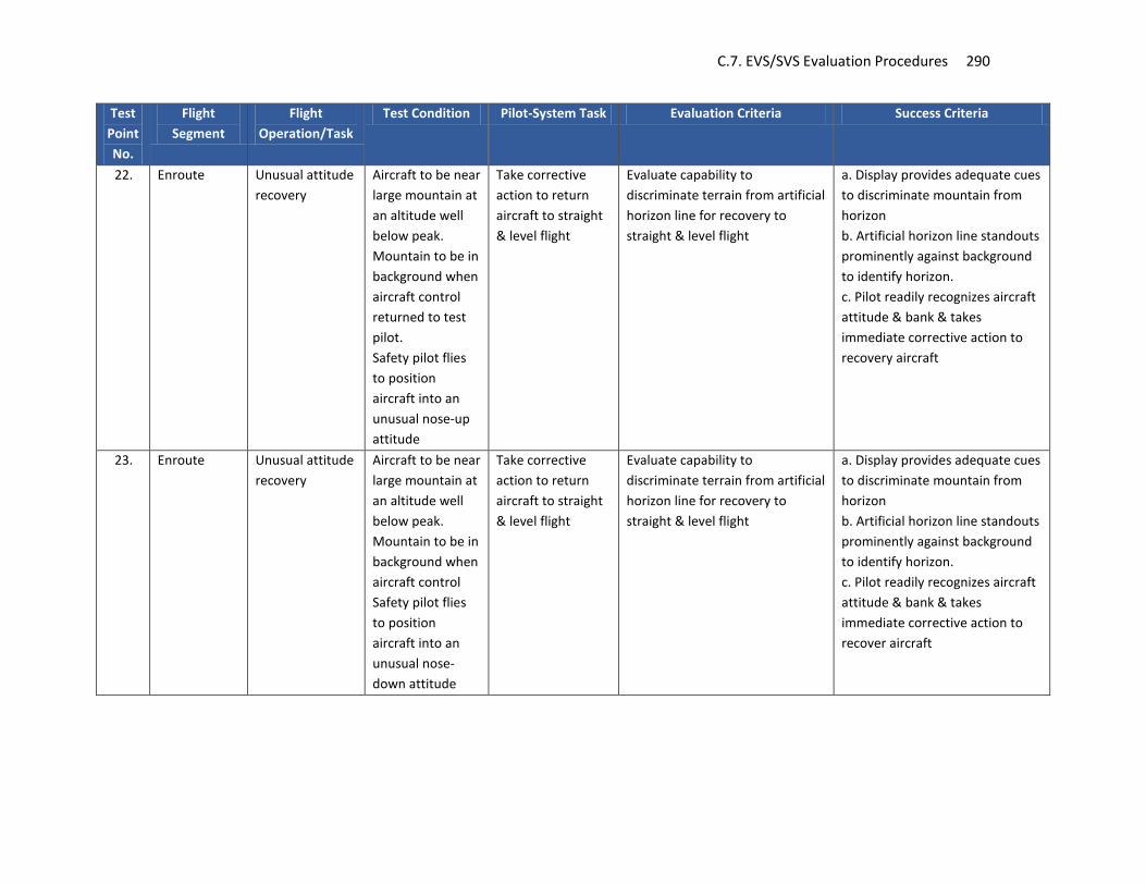
C.7. EVS/SVS Evaluation Procedures 290
Test Point No.
Flight Segment
Flight Operation/Task
Test Condition Pilot-System Task Evaluation Criteria Success Criteria
22. Enroute Unusual attitude recovery
Aircraft to be near large mountain at an altitude well below peak. Mountain to be in background when aircraft control returned to test pilot. Safety pilot flies to position aircraft into an unusual nose-up attitude
Take corrective action to return aircraft to straight & level flight
Evaluate capability to discriminate terrain from artificial horizon line for recovery to straight & level flight
a. Display provides adequate cues to discriminate mountain from horizon b. Artificial horizon line standouts prominently against background to identify horizon. c. Pilot readily recognizes aircraft attitude & bank & takes immediate corrective action to recovery aircraft
23. Enroute Unusual attitude recovery
Aircraft to be near large mountain at an altitude well below peak. Mountain to be in background when aircraft control Safety pilot flies to position aircraft into an unusual nose-down attitude
Take corrective action to return aircraft to straight & level flight
Evaluate capability to discriminate terrain from artificial horizon line for recovery to straight & level flight
a. Display provides adequate cues to discriminate mountain from horizon b. Artificial horizon line standouts prominently against background to identify horizon. c. Pilot readily recognizes aircraft attitude & bank & takes immediate corrective action to recover aircraft
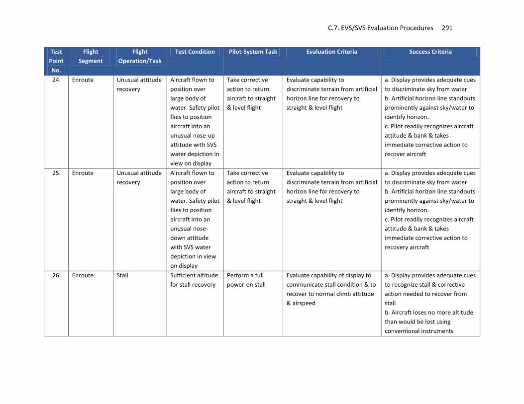
C.7. EVS/SVS Evaluation Procedures 291
Test Point No.
Flight Segment
Flight Operation/Task
Test Condition Pilot-System Task Evaluation Criteria Success Criteria
24. Enroute Unusual attitude recovery
Aircraft flown to position over large body of water. Safety pilot flies to position aircraft into an unusual nose-up attitude with SVS water depiction in view on display
Take corrective action to return aircraft to straight & level flight
Evaluate capability to discriminate terrain from artificial horizon line for recovery to straight & level flight
a. Display provides adequate cues to discriminate sky from water b. Artificial horizon line standouts prominently against sky/water to identify horizon. c. Pilot readily recognizes aircraft attitude & bank & takes immediate corrective action to recover aircraft
25. Enroute Unusual attitude recovery
Aircraft flown to position over large body of water. Safety pilot flies to position aircraft into an unusual nose-down attitude with SVS water depiction in view on display
Take corrective action to return aircraft to straight & level flight
Evaluate capability to discriminate terrain from artificial horizon line for recovery to straight & level flight
a. Display provides adequate cues to discriminate sky from water b. Artificial horizon line standouts prominently against sky/water to identify horizon. c. Pilot readily recognizes aircraft attitude & bank & takes immediate corrective action to recovery aircraft
26. Enroute Stall Sufficient altitude for stall recovery
Perform a full power-on stall
Evaluate capability of display to communicate stall condition & to recover to normal climb attitude & airspeed
a. Display provides adequate cues to recognize stall & corrective action needed to recover from stall b. Aircraft loses no more altitude than would be lost using conventional instruments

C.7. EVS/SVS Evaluation Procedures 292
Test Point No.
Flight Segment
Flight Operation/Task
Test Condition Pilot-System Task Evaluation Criteria Success Criteria
27. Enroute -Descent
Descend to predetermine altitude
No specific Select & input information to provide descend guidance to a predetermined altitude with reference to PFD pathway only
Evaluate adequacy of pathway guidance for descending to lower altitudes
Pathway guidance provides adequate cues for maintaining desired descent rate
28. Enroute Flight down valley
At an altitude & course directly over a valley, descend to a safe altitude above valley floor but below valley sides (mountains)
Descend into valley to specified altitude. Maintain heading that will result in flight down center of valley
1. Evaluate capability of PFD only to determine relative distance & elevation of nearby terrain. 2. Evaluate capability of PFD only to determine whether sufficient room exists to right/left of airplane to perform a 180 degree turn to reverse course
1. Presentation on PFD provide adequate cues to approximate distance & elevation to nearby terrain 2. Presentation on PFD provide adequate cues to determine whether sufficient space exists right/left of aircraft to perform a 180 degree turn to reverse course.
29. Enroute Flight near one or more airports
1. Evaluate airport “signposts” presented on the PFD for effectiveness & usability 2. Evaluate presentation for clutter & interference with other displayed symbology
1. Airport “signposts” provide for good geographical position awareness & aid in identifying destination airport 2. Airport “signposts” does not unduly clutter display or interference with the visibility, interpretation & use of other symbology

C.7. EVS/SVS Evaluation Procedures 293
Test Point No.
Flight Segment
Flight Operation/Task
Test Condition Pilot-System Task Evaluation Criteria Success Criteria
30. Enroute Transition from enroute to approach
At or above altitude as required by procedure
Maneuver to intercept IAF with use of PFD information only
Evaluate capability to identify, maneuver & fly to IAF
System provides adequate navigation cues to identify, maneuver & intercept IAF
31. Approach Flight from IAF to FAF
At or above altitude as required by procedure
Descend to minimum altitude for leg while maintaining course
Evaluate adequacy of symbology for descent & maintaining course track to FAF
System provides adequate cues to descend to minimum altitude for leg & maintaining acceptable course track

C.7. EVS/SVS Evaluation Procedures 294
Test Point No.
Flight Segment
Flight Operation/Task
Test Condition Pilot-System Task Evaluation Criteria Success Criteria
32. Approach Precision Approach - ILS
Each pilot must be exposed to an approach where winds necessitate crab to maintain required track. (ACO will need to evaluate at crosswinds component limits for aircraft
Perform precision ILS approach to DA in accordance with approved procedure
1. Evaluate adequacy of symbology on PFD for performance of approach 2. Evaluate SVS symbology for interference with cues & guidance presented on the PFD for the conduct of this procedure 3. Evaluate capability to use SVS display to determine aircraft to runway orientation & distance 4. Evaluate correspondence of SVS depiction to navigation guidance (CDI, HSI, etc.) 5. Evaluate effect of movement of SVS display background has on velocity perception. 6. Evaluate use of pathway to maintain acceptable horizontal & vertical positioning relative to ILS guidance 7. Evaluate the workload associated with using the pathway to fly the approach
1. PFD symbology provides adequate cues for performance of approach 2. SVS symbology does not interfere with the visibility, interpretation & use of cues & guidance presented on the PFD for the conduct of this procedure 3a. SVS aids pilot in lining up & maintaining alignment with runway throughout approach 3b. Pilot is able to approximate distance to runway with relative accuracy 4. SVS depiction corresponds directly with navigation guidance. 5. Movement of SVS background does not communicate a sense much greater than or less than actual speed over ground 6. Pathway provides acceptable guidance to maintain within legal horizontal & vertical limits of the approach 7. Pathway does not impose unacceptably high workload when used on the approach

C.7. EVS/SVS Evaluation Procedures 295
Test Point No.
Flight Segment
Flight Operation/Task
Test Condition Pilot-System Task Evaluation Criteria Success Criteria
33. Approach Missed approach Execute the missed at the MAP
Evaluate adequacy of navigation guidance to fly to the designated hold (PFD only)
a. Guidance presented on PFD provides adequate cues to climb & fly to MAP hold point b. Guidance cues on PFD does not interfere with the visibility, interpretation and use of other symbology on PFD
34. Approach GPS Approach Fly GPS approach per published procedures
Evaluate SVS display for performance of GPS approach
a. SVS provides greater pilot awareness of airport area, obstacles, aircraft position relative to runway. b. SVS display does not interference with visibility & use of other symbology on PFD display
35. Approach Instrument approach with course reversal
Normal precision approach with course reversal
Fly approach per procedure
Evaluate pathway & SVS display for effectiveness, usability & workload
Pathway & SVS display provide for acceptable guidance, readily usable & workload
36. Enroute Hold ATC instructs pilot to hold _ miles ___ (direction) on ___ radial of the ___ VORTAC, 2 mile legs Pathway presented with F/D selected
Join & maintain hold as prescribed by ATC until given further clearance using primarily PFD information
Evaluate effectiveness, usability of PFD displayed symbology for joining & flying hold
Displayed symbology provides for effective & usable guidance to join & fly hold
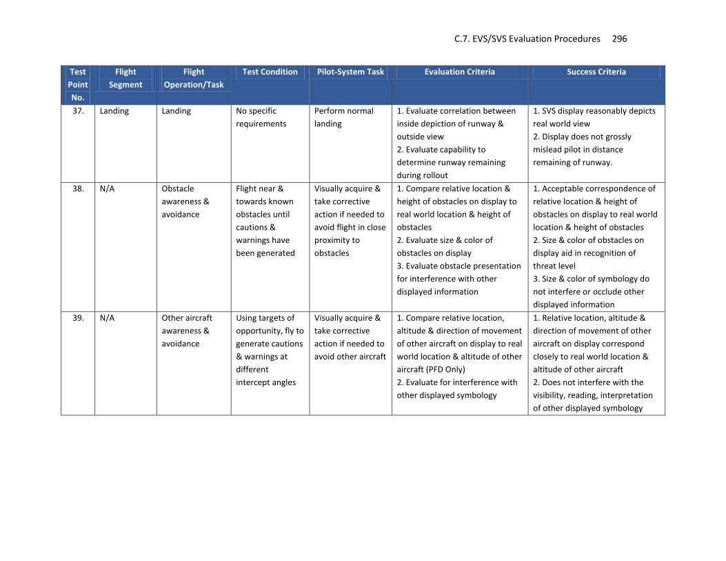
C.7. EVS/SVS Evaluation Procedures 296
Test Point No.
Flight Segment
Flight Operation/Task
Test Condition Pilot-System Task Evaluation Criteria Success Criteria
37. Landing Landing No specific requirements
Perform normal landing
1. Evaluate correlation between inside depiction of runway & outside view 2. Evaluate capability to determine runway remaining during rollout
1. SVS display reasonably depicts real world view 2. Display does not grossly mislead pilot in distance remaining of runway.
38. N/A Obstacle awareness & avoidance
Flight near & towards known obstacles until cautions & warnings have been generated
Visually acquire & take corrective action if needed to avoid flight in close proximity to obstacles
1. Compare relative location & height of obstacles on display to real world location & height of obstacles 2. Evaluate size & color of obstacles on display 3. Evaluate obstacle presentation for interference with other displayed information
1. Acceptable correspondence of relative location & height of obstacles on display to real world location & height of obstacles 2. Size & color of obstacles on display aid in recognition of threat level 3. Size & color of symbology do not interfere or occlude other displayed information
39. N/A Other aircraft awareness & avoidance
Using targets of opportunity, fly to generate cautions & warnings at different intercept angles
Visually acquire & take corrective action if needed to avoid other aircraft
1. Compare relative location, altitude & direction of movement of other aircraft on display to real world location & altitude of other aircraft (PFD Only) 2. Evaluate for interference with other displayed symbology
1. Relative location, altitude & direction of movement of other aircraft on display correspond closely to real world location & altitude of other aircraft 2. Does not interfere with the visibility, reading, interpretation of other displayed symbology

C.7. EVS/SVS Evaluation Procedures 297
Test Point No.
Flight Segment
Flight Operation/Task
Test Condition Pilot-System Task Evaluation Criteria Success Criteria
40. N/A Awareness & avoidance of terrain
Flight near & towards terrain until cautions & warnings have been generated
Awareness, recognition & action required to avoid close proximity to terrain
1. Evaluate capability of PFD display to communicate terrain proximity & need to corrective action 2. Evaluate capability to determine from PFD depiction alone approximate height of aircraft above body of water 3. Evaluate capability to recognize rising terrain near water’s edge
1. Pilot easily recognizes potential terrain conflicts & display aids in taking corrective action to avoid terrain conflicts 2. Pilot is able to acceptably judge approximate aircraft altitude above body of water from PFD depiction alone 3. Pilot correctly recognizes rising terrain beginning at water’s edge
41. N/A Ground Evaluation
On ground with external power, if necessary
Select various system functions & options related to SVS
Evaluate: 1. Control placement for accessibility, operation & feedback 2. Control labels for visibility, readability & interpretability 3. Capability to locate, select functions & options (consider menu structure)
1. Controls for use inflight are located to provide for ready access, operate consistently & appropriately, & provide adequate feedback of operation 2. Control labels are easily seen, read & interpreted 3. Menu structure facilitates locating, selecting functions & options
Note: 1) All points to be flown without use of autopilot. Autopilot evaluations will be done at the discretion of ACO. 2) It is recognized that some test points may not be feasible or capable of being flown as defined in test plan. Changes may be
necessary to address the intent of the test point. 3) Night evaluation will need to be conducted to evaluate SVS related symbology & capability to view other symbology at desired
brightness levels. 4) Based on the test aircraft, additional testing may be required for higher performance aircraft.

This page left blank intentionally.

Appendix D. Human Factors Key FAA References 299
Appendix D. Human Factors Key FAA References This appendix contains a list of documents that contain significant human factors related regulatory and guidance information related to flight deck displays and controls. All individuals working within this domain should have a good understanding and working knowledge of the documents listed in this appendix. The first seven Advisory Circulars have a heavy emphasis on human factors issues for displays and controls. The first three in the table below have the most broad and applicable human factors coverage of flight deck displays and controls. Note that many of these documents in the tables below also address topics outside the domain of human factors, so they should all be mastered, but not necessarily to the same level of proficiency. See also http://www.faa.gov/aircraft/air_cert/design_approvals/human_factors/hf-air/policy/
Advisory Circulars
AC Number Title Purpose AC 25-11A Electronic Flight Deck Displays This AC provides guidance for showing compliance
with certain requirements of Title 14, Code of Federal Regulations (CFR), part 25, as well as general guidance for the design, installation, integration, and approval of electronic flight deck displays, components, and systems installed in transport category airplanes.
AC 23.1311-1C Installation of Electronic Displays in Part 23 Airplanes
This advisory circular (AC) provides guidance for showing compliance with certain requirements of Title 14, Code of Federal Regulations (CFR), part 23, as well as general guidance for the design, installation, integration, and approval of electronic flight deck displays, components, and systems installed in part 23 category airplanes.
AC 20-175 Controls for Flight Deck Systems This advisory circular (AC) provides guidance for the installation and airworthiness approval of flight deck system control devices, from primarily a human factors perspective. It does not address primary flight controls, secondary flight controls, or controls that are not located in the flight deck. This AC addresses traditional dedicated controls such as physical switches and knobs, as well as multifunction controls such as touch screens and cursor control devices.

Appendix D. Human Factors Key FAA References 300
AC Number Title Purpose AC 25.1302-1 Installed Systems and Equipment for
Use by the Flightcrew This advisory circular (AC) describes an acceptable means of showing compliance with certain requirements of Title 14, Code of Federal Regulations (14 CFR) part 25. In particular, this AC addresses the design and approval of installed equipment intended for flight crewmembers to use from their normally seated positions on the flightdeck. It also provides recommendations for the design and evaluation of controls, displays, system behavior, and system integration, as well as design guidance for error management.
AC 25.1322-1 Flightcrew Alerting This advisory circular (AC) provides guidance for showing compliance with certain requirements of Title 14, Code of Federal Regulations (14 CFR), part 25, for the design approval of flightcrew-alerting functions. This AC addresses the type of alert function elements that should be considered (including visual, aural, and tactile or haptic elements), alert management, interface or integration of alerts with other systems, and color standardization. The appendices to this AC also provide examples for including visual and aural system elements in an alerting system.
AC 25.1523-1 Minimum Flightcrew This advisory circular (AC) sets forth a method of compliance with the requirements of § 25.1523, which contains the certification requirements for minimum flightcrew on transport category airplanes.
AC 23-1523 Minimum Flight Crew This advisory circular (AC) sets forth one method that may be used to show compliance to the requirements contained within 14 CFR 23.1523, which prescribes the certification requirements for minimum flight crew on part 23 airplanes. This AC is one method that can be used to determine workload factors and issues for normal, utility, acrobatic and commuter category airplanes. Material in this AC is neither mandatory nor regulatory in nature and does not constitute a regulation.
AC 23-8C Flight Test Guide for Certification of Part 23 Airplanes
This advisory circular (AC) sets forth an acceptable means, but not the only means, of showing compliance with Title 14 Code of Federal Regulations (14 CFR) Part 23 concerning flight tests and pilot judgements.
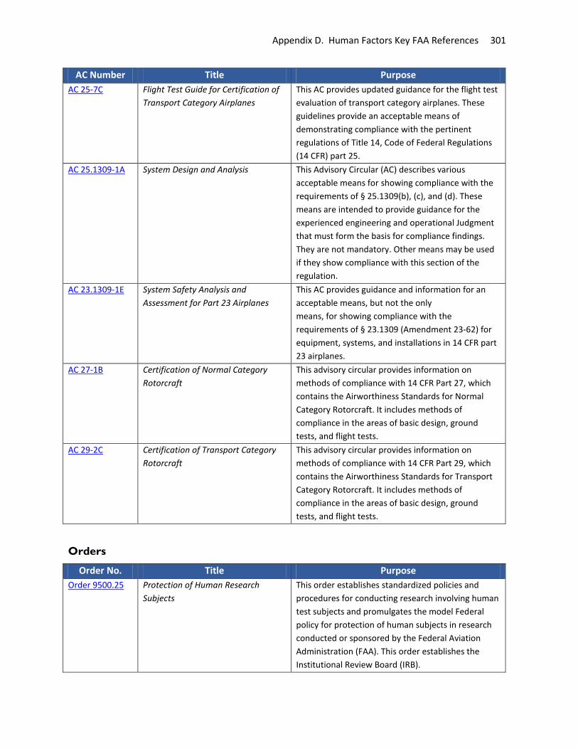
Appendix D. Human Factors Key FAA References 301
AC Number Title Purpose AC 25-7C Flight Test Guide for Certification of
Transport Category Airplanes This AC provides updated guidance for the flight test evaluation of transport category airplanes. These guidelines provide an acceptable means of demonstrating compliance with the pertinent regulations of Title 14, Code of Federal Regulations (14 CFR) part 25.
AC 25.1309-1A System Design and Analysis This Advisory Circular (AC) describes various acceptable means for showing compliance with the requirements of § 25.1309(b), (c), and (d). These means are intended to provide guidance for the experienced engineering and operational Judgment that must form the basis for compliance findings. They are not mandatory. Other means may be used if they show compliance with this section of the regulation.
AC 23.1309-1E System Safety Analysis and Assessment for Part 23 Airplanes
This AC provides guidance and information for an acceptable means, but not the only means, for showing compliance with the requirements of § 23.1309 (Amendment 23-62) for equipment, systems, and installations in 14 CFR part 23 airplanes.
AC 27-1B Certification of Normal Category Rotorcraft
This advisory circular provides information on methods of compliance with 14 CFR Part 27, which contains the Airworthiness Standards for Normal Category Rotorcraft. It includes methods of compliance in the areas of basic design, ground tests, and flight tests.
AC 29-2C Certification of Transport Category Rotorcraft
This advisory circular provides information on methods of compliance with 14 CFR Part 29, which contains the Airworthiness Standards for Transport Category Rotorcraft. It includes methods of compliance in the areas of basic design, ground tests, and flight tests.
Orders
Order No. Title Purpose Order 9500.25 Protection of Human Research
Subjects This order establishes standardized policies and procedures for conducting research involving human test subjects and promulgates the model Federal policy for protection of human subjects in research conducted or sponsored by the Federal Aviation Administration (FAA). This order establishes the Institutional Review Board (IRB).

Appendix D. Human Factors Key FAA References 302
Order No. Title Purpose Order AM 9950.3D
Aerospace Medicine Research Order This order delineates responsibilities and procedures for the review of research performed under the Office of Aerospace Medicine (AAM) Research, Engineering and Development (RE&D) Program.
Policy/Public Statements
Policy/Public Statement No.
Title Purpose
PS-ACE100-2001-004
Public Statement Number PS-ACE100-2001-004 on Guidance for Reviewing Certification Plans to Address Human Factors for Certification of Part 23 Small Airplanes
The purpose of this memorandum is to clarify Federal Aviation Administration (FAA) certification policy on human factors. This policy statement provides guidance to FAA certification teams for review of an applicant’s HFCP or the human factors (HF) components of a general certification plan when one is submitted as part of a type certification, supplemental type certification, or amended type certification project. FAA certification teams are encouraged to use this policy in reviewing certification plans.
PS-ACE100-2002-002
Installation Approval of Multi-Function Displays Using the AML STC Process; Policy Statement PS-ACE100-2002-002
This policy is to encourage use of the Approved Model List (AML) Supplemental Type Certificate (STC) AML STC approval process. This policy focuses on the use of the AML STC for installation of multiple function displays (MFDs) in Civil Air Regulations (CAR) 3 or 14 CFR part 23 airplanes or sailplanes, balloons, or airships operating under part 91, and/or part 135 rules.
PS-ANM111-1999-99-2
Guidance for Reviewing Certification Plans to Address Human Factors for Certification of Transport Airplane Flight Decks
This policy provides guidance to FAA Certification Teams that will enable them to conduct an effective review of an applicant’s Human Factors Certification Plan or the human factors components of a general Certification Plan, when one is submitted at the beginning of a type certification, supplemental type certification, or amended type certificate project. This guidance describes the sections of a Human Factors Certification Plan and the information that should be included in each section.

Appendix D. Human Factors Key FAA References 303
Policy/Public Statement No.
Title Purpose
PS-ANM100-01-03A
Factors to Consider When Reviewing an Applicant’s Proposed Human Factors Methods of Compliance for Flight Deck Certification
The FAA is presenting this information as a set of guidelines suitable for use by applicants for a type certificate (TC), supplemental type certificate (STC), or amended type certificate (ATC). The general policy stated in this document does not constitute a new regulation or create what the courts refer to as a “binding norm.” The office that implements policy should follow this policy when applicable to the specified project. Whenever an applicant’s proposed method of compliance is outside this established policy, it must be coordinated with the policy issuing office, e.g., through the issue paper process or equivalent.
PS-ANM-03-111-18
Policy Statement on the Installation of Transport Category Airplane Flightdeck Liquid Crystal Displays
The purpose of this memorandum is to clarify Federal Aviation Administration (FAA) certification policy on the installation of liquid crystal displays (LCD). This memo addresses the lack of published approval criteria for LCD technology and provides guidance on performance levels that have been found to be acceptable for LCDs used as pilot displays in the flightdeck of transport category airplanes.
PS-ANM111-2001-99-01
Improving Flightcrew Awareness During Autopilot Operation
This document announces an FAA general statement of policy applicable to the type certification of transport category airplanes. This document advises the public, in particular manufacturers of transport category airplanes and automatic flight control (autopilot) systems, that the FAA, when certifying automatic pilot installations, intends to evaluate various items that will improve the flightcrew’s awareness during autopilot operation.
PS-ANM100-2001-00113
Interim Summary of Policy and Advisory Material Available for Use In the Certification of Cabin Mounted Video Cameras Systems with Flight Deck Displays on Title 14 CFR Part 25 Aircraft
This memorandum provides a summary of policy and advisory material that should be applied when certifying cabin mounted video camera (CMVC) systems with flight deck display of the video image on Title 14 Code of Federal Regulations (CFR) part 25 aircraft.
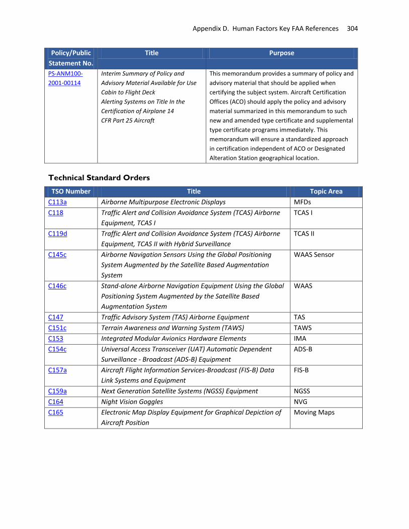
Appendix D. Human Factors Key FAA References 304
Policy/Public Statement No.
Title Purpose
PS-ANM100-2001-00114
Interim Summary of Policy and Advisory Material Available for Use Cabin to Flight Deck Alerting Systems on Title In the Certification of Airplane 14 CFR Part 25 Aircraft
This memorandum provides a summary of policy and advisory material that should be applied when certifying the subject system. Aircraft Certification Offices (ACO) should apply the policy and advisory material summarized in this memorandum to such new and amended type certificate and supplemental type certificate programs immediately. This memorandum will ensure a standardized approach in certification independent of ACO or Designated Alteration Station geographical location.
Technical Standard Orders
TSO Number Title Topic Area C113a Airborne Multipurpose Electronic Displays MFDs C118 Traffic Alert and Collision Avoidance System (TCAS) Airborne
Equipment, TCAS I TCAS I
C119d Traffic Alert and Collision Avoidance System (TCAS) Airborne Equipment, TCAS II with Hybrid Surveillance
TCAS II
C145c Airborne Navigation Sensors Using the Global Positioning System Augmented by the Satellite Based Augmentation System
WAAS Sensor
C146c Stand-alone Airborne Navigation Equipment Using the Global Positioning System Augmented by the Satellite Based Augmentation System
WAAS
C147 Traffic Advisory System (TAS) Airborne Equipment TAS C151c Terrain Awareness and Warning System (TAWS) TAWS C153 Integrated Modular Avionics Hardware Elements IMA C154c Universal Access Transceiver (UAT) Automatic Dependent
Surveillance - Broadcast (ADS-B) Equipment ADS-B
C157a Aircraft Flight Information Services-Broadcast (FIS-B) Data Link Systems and Equipment
FIS-B
C159a Next Generation Satellite Systems (NGSS) Equipment NGSS C164 Night Vision Goggles NVG C165 Electronic Map Display Equipment for Graphical Depiction of
Aircraft Position Moving Maps

Appendix D. Human Factors Key FAA References 305
Other Key Human Factors References
Cardosi, K. and Huntley, M. S. (1993). Human Factors for Flight Deck Certification Personnel (DOTVNTSC-FAA-93-4; DOT-FAA-RD-93-5). Cambridge, MA: US DOT Volpe National Transportation Systems Center. Available from: http://ntl.bts.gov/lib/33000/33500/33543/33543.pdf
Federal Aviation Administration. (1996). The Interfaces Between Flightcrews and Modern Flight Deck Systems. Washington, DC: US DOT Federal Aviation Administration. Available from: https://www.faa.gov/aircraft/air_cert/design_approvals/csta/publications/media/fltcrews_fltdeck.pdf
Federal Aviation Administration. (2013). Operational Use of Flight Path Management Systems: Final Report of the Performance-based operations Aviation Rulemaking Committee/Commercial Aviation Safety Team Flight Deck Automation Working Group. Washington, DC: US DOT Federal Aviation Administration. Available from: http://www.faa.gov/about/office_org/headquarters_offices/avs/offices/afs/afs400/parc/parc_reco/media/2013/130908_PARC_FltDAWG_Final_Report_Recommendations.pdf
McAnulty, D. M. (1995). Guidelines for the Design of GPS and LORAN Receiver Controls and Displays (DOT-VNTSC-FAA-95-7; DOT/FAA/RD-95-1). Cambridge, MA: USDOT Volpe National Transportation Systems Center. Available from: http://ntl.bts.gov/lib/33000/33500/33504/33504.pdf
Notice (N) 8110.98, Addressing Human Factors/Pilot Interface Issues of Complex, Integrated Avionics as Part of the Technical Standard Order (TSO) Process, May 10, 2002. Washington, DC: US DOT Federal Aviation Administration. Available from: http://www.airweb.faa.gov/Regulatory_and_Guidance_Library%5CrgOrders.nsf/0/6252A89C3CA8916885256D2000773D39?OpenDocument
Williams, J. H. (1997). Description of the FAA Avionics Certification Process. Unpublished document.

This page left blank intentionally.

Appendix E. Part 23, 25, 27, and 29 Regulations Related to Human Factors 307
Appendix E. Part 23, 25, 27, and 29 Regulations Related to Human Factors The intent of this appendix is to assist the FAA and industry in identifying some of the key Part 23, 25, 27, and 29 regulations that are under the purview of Aircraft Certification that are potentially related to human factors. There are a number of regulations that address human factors-related aspects. Many of these same regulations also involve or address areas other than human factors, or are considered to be part of other engineering disciplines simply by its location in the regulations. Additionally, in some cases, the regulation is written in general terms that it may to some extent be applicable to all engineering disciplines within the certification office. Table E.1 provides a list of some of the most frequently cited Part 23, 25, 27, and 29 regulations that address human factors/pilot interface issues. Table E.2 of this appendix provides a subset of the text of some of these Part 25 regulations and provides a means to determine if there is similar wording in the corresponding Part 23, 27, and 29 regulations. The text is provided so that this appendix can easily be referenced on-site, during Aircraft Certification project meetings, as opposed to having to carry the entire book of regulations. It is not the intent of this section to limit or prescribe the regulations to the discipline of human factors, nor are the list presented below all inclusive, but rather are intended to highlight those regulations where human factors involvement is typical. This is not a comprehensive list of human factors topics applicants must address during aircraft certification; rather, the list identifies examples of common human factors topics in aircraft certification. Table E.1. Key airworthiness regulations related to human factors
23 25 27 29 Topic Section Content
SUBPART B – FLIGHT 27.33 29.33 General Main rotor speed and pitch limits 23.45 29.45 Performance General
27.51 29.51 Performance Part 27: Takeoff
Part 29: Takeoff data: General 23.55 Performance Accelerate- stop distance
27.75 29.75 Performance Part 27: Landing
Part 29: Landing: General 25.101 Performance General

Appendix E. Part 23, 25, 27, and 29 Regulations Related to Human Factors 308
23 25 27 29 Topic Section Content 25.105 Performance Takeoff 25.109 Performance Accelerate-Stop distance 25.125 Performance Landing 23.141 27.141 29.141 Flight characteristics General
23.143 25.143 27.143 29.143 Part 23 & 25: Controllability and Maneuverability
General
Part 27 & 29: Flight Characteristics Controllability and Maneuverability 23.145 25.145 Controllability and Maneuverability Longitudinal control 23.149 25.149 Controllability and Maneuverability Minimum control speed 23.173 25.173 27.173 29.173 Stability Static longitudinal stability
23.177 25.177 27.177 29.177 Stability Part 23: Static directional and lateral stability
Part 25: Static lateral-directional stability Parts 27 & 29: Static directional stability
23.181 25.181 29.181 Stability Dynamic stability
23.203 25.203 Stalls Part 23: Turning flight and accelerated turning stalls
Parts 25: Stall characteristics 23.207 25.207 Stalls Stall warning
23.233 25.233 Ground and Water Handling Characteristics
Directional stability and control
23.251 25.251 27.251 29.251 Miscellaneous Flight Requirements Parts 23 & 25: Vibration and buffeting
Parts 27 & 29: Vibration 23.253 25.253 Miscellaneous Flight Requirements High-speed characteristics SUBPART D – DESIGN AND CONSTRUCTION
23.601 25.601 27.601 29.601 General Parts 23 & 25: General
Parts 27 & 29: Design 23.671 25.671 27.671 29.671 Control Systems General
23.672 25.672 27.672 29.672
Control Systems Parts 23 & 25: Stability augmentation and automatic and power-operated systems Parts 27 & 29: Stability augmentation, automatic, and power-operated systems
23.677 25.677 Control Systems Trim Systems

Appendix E. Part 23, 25, 27, and 29 Regulations Related to Human Factors 309
23 25 27 29 Topic Section Content
23.679 25.679 27.679 29.679 Control Systems Parts 23, 27, & 29: Control system locks
Part 25: Control system gust locks 23.685 25.685 27.685 29.685 Control Systems Control system details
23.697 25.697 Control Systems Part 23: Wing flap controls
Part 25: Lift and drag devices, controls
23.699 25.699 Control Systems Part 23: Wing flap position indicator
Part 25: Lift and drag device indicator 23.703 25.703 Control Systems Takeoff warning system
23.729 25.729 27.729 29.729 Landing Gear Part 23: Landing gear extension and retraction system
Parts 25, 27, & 29: Retracting mechanism 23.745 Landing Gear Nose/tail wheel steering 23.771 25.771 27.771 29.771 Personnel & Cargo Accommodations Pilot compartment 23.773 25.773 27.773 29.773 Personnel and Cargo Accommodations Pilot compartment view 23.777 25.777 27.777 29.777 Personnel and Cargo Accommodations Cockpit controls 23.779 25.779 27.779 29.779 Personnel and Cargo Accommodations Motion and effect of cockpit controls 23.781 25.781 Personnel and Cargo Accommodations Cockpit control knob shape
23.785 25.785 27.785 29.785
Personnel and Cargo Accommodations Part 23: Seats, berths, litters, safety belts, and shoulder harnesses Part 25: Seats, berths, safety belts, and harnesses Parts 27 & 29: Seats, berths, litters, safety belts, and harnesses
23.807 27.807 Personnel and Cargo Accommodations Emergency exits
25.809 29.809 Part 25: Emergency Provision Part 27: Personnel and Cargo Accommodations
Emergency exit arrangement
Subpart E – Powerplant
25.941 General Inlet, engine, and exhaust compatibility 23.1141 25.1141 27.1141 29.1141 Powerplant Controls and Accessories Powerplant Controls: General 23.1142 25.1142 29.1142 Powerplant Controls and Accessories Auxiliary power unit controls 23.1143 25.1143 27.1143 29.1143 Powerplant Controls and Accessories Engine controls

Appendix E. Part 23, 25, 27, and 29 Regulations Related to Human Factors 310
23 25 27 29 Topic Section Content 23.1145 25.1145 27.1145 29.1145 Powerplant Controls and Accessories Ignition switches 23.1147 25.1147 25.1147 29.1147 Powerplant Controls and Accessories Mixture controls 23.1149 25.1149 Powerplant Controls and Accessories Propeller speed and pitch controls 23.1153 25.1153 Powerplant Controls and Accessories Propeller feathering controls
23.1155 25.1155
Powerplant Controls and Accessories Part 23: Turbine engine reverse thrust and propeller pitch settings below the flight regime Part 25: Reverse thrust and propeller pitch settings below the flight regime
23.1157 25.1157 29.1157 Powerplant Controls and Accessories Carburetor air temperature controls 25.1159 29.1159 Powerplant Controls and Accessories Supercharger controls 25.1161 Powerplant Controls and Accessories Fuel jettisoning system controls
Subpart F – Equipment
23.1301 25.1301 27.1301 29.1301 General Function and Installation 25.1302 General Installed systems and equipment for use by the flightcrew 23.1303 25.1303 27.1303 29.1303 General Flight and navigation instruments 23.1305 25.1305 27.1305 29.1305 General Powerplant instruments 23.1309 25.1309 27.1309 29.1309 General Equipment, systems, and installations 23.1311 Instruments: Installation Electronic display instrument systems 23.1321 25.1321 27.1321 29.1321 Instruments: Installation Arrangement and visibility
23.1322 25.1322 27.1322 29.1322 Instruments: Installation Parts 23, 27, & 29: Warning, caution, and advisory lights
Part 25: Flightcrew Alerting 23.1326 25.1326 Instruments: Installation Pitot heat indication systems.
23.1329 25.1329 27.1329 29.1329 Instruments: Installation Parts 23, 27, & 29: Automatic pilot system
Part 25: Flight guidance system
23.1331 25.1331 Instruments: Installation Part 23: Instruments using a power source
Part 25: Instruments using a power supply 23.1335 27.1335 29.1335 Instruments: Installation Flight director systems 23.1357 25.1357 27.1357 29.1357 Electrical Systems and Equipment Circuit protective devices 23.1381 25.1381 27.1381 29.1381 Lights Instrument lights 23.1447 25.1447 Miscellaneous Equipment Equipment standards for oxygen dispensing units.

Appendix E. Part 23, 25, 27, and 29 Regulations Related to Human Factors 311
23 25 27 29 Topic Section Content
Subpart G – Operating Limitations and Information
23.1523 25.1523 27.1523 29.1523 Part 25, 27, & 29: Operating Limitations Minimum flight crew
23.1525 25.1525 27.1525 29.1525 Part 25, 27, & 29: Operating Limitations Parts 23 & 25: Kinds of operation
Parts 27 & 29: Kinds of operations 23.1541 25.1541 27.1541 29.1541 Markings and Placards General 23.1543 25.1543 27.1543 29.1543 Markings and Placards Instrument markings: general
23.1545 25.1545 27.1545 29.1545 Markings and Placards Parts 23, 27, & 29: Airspeed indicator
Part 25: Airspeed limitation information 23.1555 25.1555 27.1555 29.1555 Markings and Placards Control markings
23.1563 25.1563 Markings and Placards Part 23: Airspeed placards
Part 25: Airspeed placard Table E.2 below contains a subset of the Part 25 regulations and provides a means to determine if similar wording is provided in the corresponding Part 23, 27, and 29 regulations. Note that the text in Table E.2 primarily contains only partial excerpts of the regulations, in order to keep this appendix concise. The reader should refer to the source guidance for the full text. Table E.2. Comparison of Part 23, 27, and 29 regulations related to human factors to Part 25 regulations related to human factors.
Part 25 Regulations Related to Human Factors Part 23 Part 27 Part 29
Subpart B – Flight
Section 25.101(h) states that “The procedures established [for accelerate-stop distances, takeoff, landing, changes in the airplane’s configuration, speed, power, and thrust, balked landings, and missed approaches] must --
No No No
(1) Be able to be consistently executed in service by crews of average skill;
(2) Use methods or devices that are safe and reliable; and
(3) Include allowance for any time delays, in the execution of the procedures, that may reasonably be expected in service.”
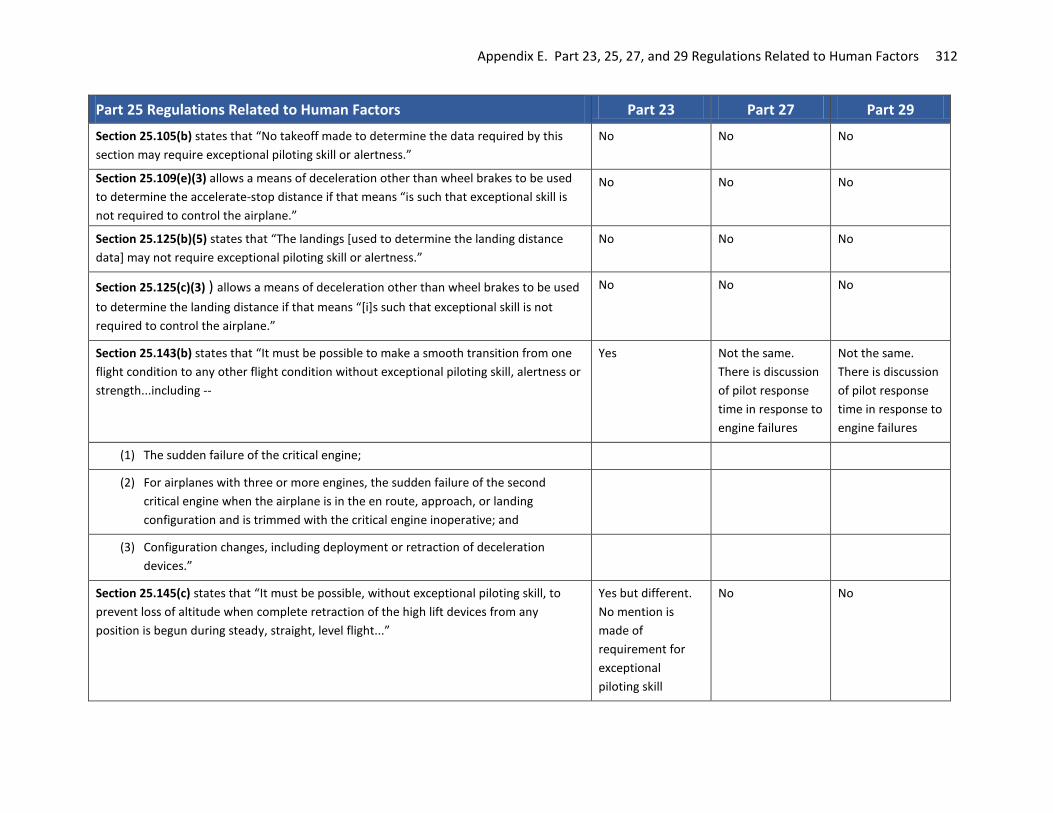
Appendix E. Part 23, 25, 27, and 29 Regulations Related to Human Factors 312
Part 25 Regulations Related to Human Factors Part 23 Part 27 Part 29
Section 25.105(b) states that “No takeoff made to determine the data required by this section may require exceptional piloting skill or alertness.”
No No No
Section 25.109(e)(3) allows a means of deceleration other than wheel brakes to be used to determine the accelerate-stop distance if that means “is such that exceptional skill is not required to control the airplane.”
No No No
Section 25.125(b)(5) states that “The landings [used to determine the landing distance data] may not require exceptional piloting skill or alertness.”
No No No
Section 25.125(c)(3) ) allows a means of deceleration other than wheel brakes to be used to determine the landing distance if that means “[i]s such that exceptional skill is not required to control the airplane.”
No No No
Section 25.143(b) states that “It must be possible to make a smooth transition from one flight condition to any other flight condition without exceptional piloting skill, alertness or strength...including --
Yes Not the same. There is discussion of pilot response time in response to engine failures
Not the same. There is discussion of pilot response time in response to engine failures
(1) The sudden failure of the critical engine;
(2) For airplanes with three or more engines, the sudden failure of the second critical engine when the airplane is in the en route, approach, or landing configuration and is trimmed with the critical engine inoperative; and
(3) Configuration changes, including deployment or retraction of deceleration devices.”
Section 25.145(c) states that “It must be possible, without exceptional piloting skill, to prevent loss of altitude when complete retraction of the high lift devices from any position is begun during steady, straight, level flight...”
Yes but different. No mention is made of requirement for exceptional piloting skill
No No

Appendix E. Part 23, 25, 27, and 29 Regulations Related to Human Factors 313
Part 25 Regulations Related to Human Factors Part 23 Part 27 Part 29
Section 25.149(d) states that “...during recovery [during the flight tests to establish VMC],
the airplane may not assume any dangerous attitude or require exceptional piloting skill, alertness, or strength to prevent a heading change of more than 20 degrees.”
No No
Section 25.149(e) requires VMCG to be determined “using normal piloting skill.” No No
Section 25.149(h) states that “the airplane may not...require exceptional piloting skill, alertness, or strength [in determining VMCL and VMCL-2]...”
No No
No part 25 equivalent to 27.171. No part 23 equivalent to 27.171.
27.171 states that “the rotorcraft must be able to be flown, without undue pilot fatigue or strain, in any normal maneuver for a period of time as long as that expected in normal operation…”
Same as Part 27
Section 25.173(d) allows some neutral static longitudinal stability “if exceptional attention on the part of the pilot is not required to return to and maintain the desired trim speed and altitude.”
No mention of pilot attention.
No mention of pilot attention.
Section 25.177(d) states that “[t]he dihedral effect...may be negative provided the divergence is gradual, easily recognized, and easily controlled by the pilot.”
27.177 says “Sufficient cues must accompany sideslip to alert the pilot when approaching sideslip limits.”
29.177 says “Sufficient cues must accompany sideslip to alert the pilot when approaching sideslip limits.”
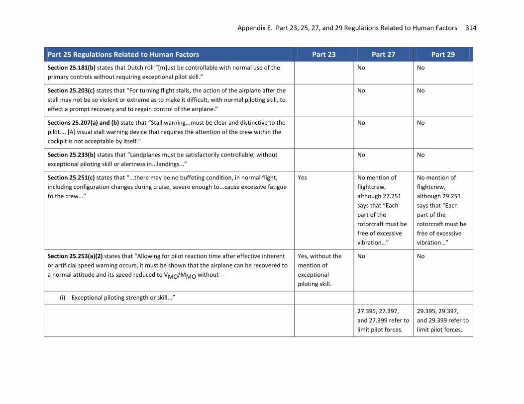
Appendix E. Part 23, 25, 27, and 29 Regulations Related to Human Factors 314
Part 25 Regulations Related to Human Factors Part 23 Part 27 Part 29
Section 25.181(b) states that Dutch roll “[m]ust be controllable with normal use of the primary controls without requiring exceptional pilot skill.”
No No
Section 25.203(c) states that “For turning flight stalls, the action of the airplane after the stall may not be so violent or extreme as to make it difficult, with normal piloting skill, to effect a prompt recovery and to regain control of the airplane.”
No No
Sections 25.207(a) and (b) state that “Stall warning...must be clear and distinctive to the pilot…. [A] visual stall warning device that requires the attention of the crew within the cockpit is not acceptable by itself.”
No No
Section 25.233(b) states that “Landplanes must be satisfactorily controllable, without exceptional piloting skill or alertness in...landings...”
No No
Section 25.251(c) states that “...there may be no buffeting condition, in normal flight, including configuration changes during cruise, severe enough to...cause excessive fatigue to the crew...”
Yes No mention of flightcrew, although 27.251 says that “Each part of the rotorcraft must be free of excessive vibration…”
No mention of flightcrew, although 29.251 says that “Each part of the rotorcraft must be free of excessive vibration…”
Section 25.253(a)(2) states that “Allowing for pilot reaction time after effective inherent or artificial speed warning occurs, it must be shown that the airplane can be recovered to a normal attitude and its speed reduced to VMO/MMO without --
Yes, without the mention of exceptional piloting skill.
No No
(i) Exceptional piloting strength or skill...”
27.395, 27.397, and 27.399 refer to limit pilot forces.
29.395, 29.397, and 29.399 refer to limit pilot forces.

Appendix E. Part 23, 25, 27, and 29 Regulations Related to Human Factors 315
Part 25 Regulations Related to Human Factors Part 23 Part 27 Part 29
Section 25.601 that “The airplane may not have design features or details that experience has shown to be hazardous or unreliable. The suitability of each questionable design detail and part must be established by tests.”
Similar wording. Scope of applicability is more limited.
Yes Similar
Subpart D -- Design And Construction
Section 25.671(a) states that “Each control and control system must operate with the ease, smoothness, and positiveness appropriate to its function.”
Similar Yes Yes
Section 25.671(c) states that “The airplane must be shown by analysis, tests, or both, to be capable of continued safe flight and landing after any of the following failures or jamming in the flight control system...without requiring exceptional piloting skill or strength. Probable malfunctions must have only minor effects on control system operation and must be capable of being readily counteracted by the pilot.”
No 29.671( c) says “A means must be provided to allow full control movement of all primary flight controls prior to flight, or a means must be provided that will allow the pilot to determine that full control authority is available prior to flight.”
Section 25.672(a) states that “A warning which is clearly distinguishable to the pilot under expected flight conditions without requiring his attention must be provided for any failure in the stability augmentation system or in any other automatic or power-operated system which could result in an unsafe condition if the pilot were not aware of the failure. Warning systems must activate the control systems.”
Yes Yes Yes

Appendix E. Part 23, 25, 27, and 29 Regulations Related to Human Factors 316
Part 25 Regulations Related to Human Factors Part 23 Part 27 Part 29
Section 25.672(b) states that “The design of the stability augmentation system or of any other automatic or power-operated system must permit initial counteraction of failures of the type specified in § 25.671(c) without requiring exceptional pilot skill or strength, by either the deactivation of the system, or a failed portion thereof, or by overriding the failure by movement of the flight controls in the normal sense.”
Yes Similar Similar
Sections 25.677(a) and (b) require trim controls “be designed to prevent inadvertent or abrupt operation and to operate in the plane, and with the sense of motion, of the airplane...There must be means adjacent to the trim control to indicate the direction of the control movement relative to the airplane motion. In addition, there must be clearly visible means to indicate the position of the trim device with respect to the range of adjustment.”
Yes No No
Section 25.679 requires that if gust locks, when engaged, prevent normal operation of the control surfaces by the pilot, they must “automatically disengage when the pilot operates the primary flight controls in a normal manner; or limit the operation of the airplane so that the pilot receives unmistakable warning at the start of takeoff.”
Yes Similar Similar
Section 25.685(a) and (b) states that “…each control system must be designed and installed to prevent jamming, chafing…” and a means must be provided “in the cockpit to prevent the entry of foreign objects into places where they would jam the [control] system.”
Yes Yes Yes
Section 25.697 states:
“(a) Each lift device control must be designed so that the pilots can place the device in any takeoff, en route, approach, or landing position...Lift and drag devices must maintain the selected positions, except for movement produced by an automatic positioning or load limiting device, without further attention by the pilots.
Yes No No

Appendix E. Part 23, 25, 27, and 29 Regulations Related to Human Factors 317
Part 25 Regulations Related to Human Factors Part 23 Part 27 Part 29
(b) Each lift and drag device control must be designed and located to make inadvertent operation improbable. Lift and drag devices intended for ground operation only must have means to prevent the inadvertent operation of their controls in flight if that operation could be hazardous.
No No
(c) The rate of motion of the surfaces in response to the operation of the control and the characteristics of the automatic positioning or load limiting device must give satisfactory flight and performance characteristics under steady or changing conditions of airspeed, engine power, and airplane attitude...”
Similar – not same wording
No No
Section 25.699 states: Similar - not same wording
No No
“(a) There must be means to indicate to the pilots the position of each lift or drag device having a separate control in the cockpit to adjust its position. In addition, an indication of unsymmetrical operation or other malfunction in the lift or drag device systems must be provided when such indication is necessary to enable the pilots to prevent or counteract an unsafe flight or ground condition, considering the effects on flight characteristics and performance.
(b) There must be means to indicate to the pilots the takeoff, en route, approach, and landing lift device positions.
(c) If any extension of the lift and drag devices beyond the landing position is possible, the controls must be clearly marked to identify this range of extension.”
Section 25.703 states: Similar - not same wording
No No
“A takeoff warning system must be installed and must meet the following requirements:
(a) The system must provide to the pilots an aural warning that is automatically activated during the initial portion of the takeoff roll if the airplane is in a configuration...that would not allow a safe takeoff...”

Appendix E. Part 23, 25, 27, and 29 Regulations Related to Human Factors 318
Part 25 Regulations Related to Human Factors Part 23 Part 27 Part 29
Section 25.729(e) requires “a landing gear position indicator...or other means to inform the pilot that the gear is secured in the [proper] position…. The flightcrew must be given an aural warning that functions continuously, or is periodically repeated, if a landing is attempted when the landing gear is not locked down. The warning must be given in sufficient time to allow the landing gear to be locked down or a go-around to be made. There must not be a manual shut-off means readily available to the flightcrew for the warning...such that it could be operated instinctively, inadvertently, or by habitual reflexive action. The system used to generate the aural warning must be designed to eliminate false or inappropriate alerts.”
Yes Similar Some words here and in 29.729(g), shorter and less specific.
Section 25.771 states: Yes Yes
“(a) Each pilot compartment and its equipment must allow the minimum flight crew...to perform their duties without unreasonable concentration or fatigue...
Yes
(c) ...the airplane must be controllable with equal safety from either pilot seat.
(d) The pilot compartment must be constructed so that, when flying in rain or snow, it will not leak in a manner that will distract the crew...
(e) Vibration and noise characteristics of cockpit equipment may not interfere with safe operation of the airplane.”
Section 25.773 provides requirements for clear and undistorted view from the pilot compartment.
Yes Yes Yes
Section 25.777 requires:
“(a) Each cockpit control...[to] be located to provide convenient operation and to prevent confusion and inadvertent operation.
Yes Yes Yes
(b) The direction of movement of cockpit controls must... correspond to the sense … of the operation upon the airplane or upon the part operated. Controls of a variable nature using a rotary motion must move clockwise from the off position, through an increasing range, to the full on position.
Similar to 27.779(a)
Similar to 29.779(a)

Appendix E. Part 23, 25, 27, and 29 Regulations Related to Human Factors 319
Part 25 Regulations Related to Human Factors Part 23 Part 27 Part 29
(c) The controls must be located and arranged, with respect to the pilots’ seats, so that there is full and unrestricted movement of each control without interference from the cockpit structure or the clothing of the minimum flightcrew...
23.777(b) 27.777(b) similar 29.777(b) similar, but height range requirements are to 6’0, instead of 6’3” as it states in Part 25.
(d) Identical powerplant controls for each engine must be located to prevent confusion as to the engines they control.
23.777(e) No No
(e) ...lift device controls must be located on top of the pedestal... No No
(f) The landing gear control must be located forward of the throttles and must be operable by each pilot when seated...
Different wording No No
(g) Control knobs must be shaped in accordance with § 25.781. In addition, the knobs must be of the same color, and this color must contrast with the color of control knobs for other purposes and the surrounding cockpit.
No No
(h) If a flight engineer is required..., the airplane must have a flight engineer station located and arranged so that the flight crewmembers can perform their functions efficiently and without interfering with each other.”
No No
Section 25.779 prescribes requirements for the motion and effect of the cockpit controls. Yes Yes Yes
Section 25.781 prescribes requirements for the shape of cockpit control knobs. Yes No No
Section 25.785 states:
“(g) Each seat at a flight deck station must have a restraint system consisting of a combined safety belt and shoulder harness with a single-point release that permits the flight deck occupant, when seated with the restraint system fastened, to perform all of the occupant's necessary flight deck functions. There must be a means to secure each combined restraint system when not in use to prevent interference with the operation of the airplane and with rapid egress in an emergency.

Appendix E. Part 23, 25, 27, and 29 Regulations Related to Human Factors 320
Part 25 Regulations Related to Human Factors Part 23 Part 27 Part 29
…(k) Each projecting object that would injure persons seated or moving about the airplane in normal flight must be padded.”
Section 25.809 states:
(a) Each emergency exit, including each flightcrew emergency exit, must be a moveable door or hatch in the external walls of the fuselage, allowing an unobstructed opening to the outside. In addition, each emergency exit must have means to permit viewing of the conditions outside the exit when the exit is closed. ... The likely areas of evacuee ground contact must be viewable during all lighting conditions with the landing gear extended as well as in all conditions of landing gear collapse.
(b) Each emergency exit must be openable from the inside and the outside except that sliding window emergency exits in the flight crew area need not be openable from the outside if other approved exits are convenient and readily accessible to the flight crew area. Each emergency exit must be capable of being opened, when there is no fuselage deformation…
(c) The means of opening emergency exits must be simple and obvious; may not require exceptional effort; and must be arranged and marked so that it can be readily located and operated, even in darkness. Internal exit-opening means involving sequence operations (such as operation of two handles or latches, or the release of safety catches) may be used for flightcrew emergency exits if it can be reasonably established that these means are simple and obvious to crewmembers trained in their use….
(h) When required by the operating rules for any large passenger-carrying turbojet-powered airplane, each ventral exit and tailcone exit must be—
(1) Designed and constructed so that it cannot be opened during flight; and
(2) Marked with a placard readable from a distance of 30 inches and installed at a conspicuous location near the means of opening the exit, stating that the exit has been designed and constructed so that it cannot be opened during flight.

Appendix E. Part 23, 25, 27, and 29 Regulations Related to Human Factors 321
Part 25 Regulations Related to Human Factors Part 23 Part 27 Part 29
Subpart E -- Powerplant
Section 25.941 states that “for airplanes using variable inlet or exhaust system geometry, or both --
…(b)The dynamic effects of the operation of these (including consideration of probable malfunctions) upon the aerodynamic control of the airplane may not result in any condition that would require exceptional skill, alertness, or strength on the part of the pilot to avoid exceeding an operational or structural limitation of the airplane; and
(c) In showing compliance with paragraph (b) of this section, the pilot strength required may not exceed the limits set forth in § 25.143(d), subject to the conditions set forth in paragraphs (e) and (f) of § 25.143.”
Sections 25.1141, 25.1142, 25.1143, 25.1145, 25.1147, 25.1149, 25.1153, 25.1155, 25.1157, 25.1159, and 25.1161 prescribe requirements for powerplant controls (general), auxiliary power unit controls, engine controls, ignition switches, mixture controls, propeller speed and pitch controls, propeller feathering controls, reverse thrust and propeller pitch settings below the flight regime, carburetor air temperature controls, supercharger controls, and fuel jettisoning system controls, respectively.
Yes - but numbering of sections is not the same. In Part 23, starts with 23.901
27.779 (b) discusses engine power controls. 27.955(c) discusses preventing interruption of fuel flow to an engine without attention by flightcrew.
Yes, except no 29.1149, 1155, 1161. 29.1151 discusses rotor brake controls; no Part 25.

Appendix E. Part 23, 25, 27, and 29 Regulations Related to Human Factors 322
Part 25 Regulations Related to Human Factors Part 23 Part 27 Part 29
Subpart F – Equipment
Section 25.1301
(a) Each item of installed equipment must— (1) Be of a kind and design appropriate to its intended function;\ (2) Be labeled as to its identification, function, or operating limitations, or any
applicable combination of these factors; (3) Be installed according to limitations specified for that equipment; and (4) Function properly when installed.
…
Yes, identical wording- slightly different structure/paragraph numbering
Yes, identical wording
Yes, identical wording
Section 25.1302
Installed systems and equipment for use by the flightcrew. This section applies to installed systems and equipment intended for flightcrew members' use in operating the airplane from their normally seated positions on the flight deck. The applicant must show that these systems and installed equipment, individually and in combination with other such systems and equipment, are designed so that qualified flightcrew members trained in their use can safely perform all of the tasks associated with the systems' and equipment's intended functions. Such installed equipment and systems must meet the following requirements:
No No No
(a) Flight deck controls must be installed to allow accomplishment of all the tasks required to safely perform the equipment's intended function, and information must be provided to the flightcrew that is necessary to accomplish the defined tasks.

Appendix E. Part 23, 25, 27, and 29 Regulations Related to Human Factors 323
Part 25 Regulations Related to Human Factors Part 23 Part 27 Part 29 (b) Flight deck controls and information intended for the flightcrew's use must: (1) Be provided in a clear and unambiguous manner at a resolution and precision
appropriate to the task; (2) Be accessible and usable by the flightcrew in a manner consistent with the
urgency, frequency, and duration of their tasks; and (3) Enable flightcrew awareness, if awareness is required for safe operation, of
the effects on the airplane or systems resulting from flightcrew actions.
(c) Operationally-relevant behavior of the installed equipment must be: (1) Predictable and unambiguous; and (2) Designed to enable the flightcrew to intervene in a manner appropriate to
the task.
(d) To the extent practicable, installed equipment must incorporate means to enable the flightcrew to manage errors resulting from the kinds of flightcrew interactions with the equipment that can be reasonably expected in service. This paragraph does not apply to any of the following:
(1) Skill-related errors associated with manual control of the airplane; (2) Errors that result from decisions, actions, or omissions committed with
malicious intent; (3) Errors arising from a crewmember's reckless decisions, actions, or omissions
reflecting a substantial disregard for safety; and (4) Errors resulting from acts or threats of violence, including actions taken
under duress.
Section 25.1303 prescribes the flight and navigation instruments that are required. Yes Yes - but fewer instruments are required.
Yes - not all the same requirements.
Section 25.1305 prescribes the powerplant instruments that are required. Yes Yes Yes
Section 25.1309 requires that

Appendix E. Part 23, 25, 27, and 29 Regulations Related to Human Factors 324
Part 25 Regulations Related to Human Factors Part 23 Part 27 Part 29
“(a) The equipment, systems, and installations … must be designed to ensure that they perform their intended functions under any foreseeable operating condition.
Scope of applicability is more limited.
Scope of applicability is more limited.
Yes
(b) The airplane systems and associated components... must be designed so that...the occurrence of...failure conditions which would reduce the...ability of the crew to cope with adverse operating conditions is improbable.
See 23.1309(c). Wording is different. Scope of applicability is more limited.
Wording is significantly different. Scope of applicability is more limited.
Wording is significantly different. Scope of applicability is more limited.
(c) Warning information must be provided to alert the crew to unsafe system operating conditions, and to enable them to take appropriate corrective action. Systems, controls, and associated monitoring and warning means must be designed to minimize crew errors which could create additional hazards.
No Very different wording and scope of applicability.
Yes
(d) ...The [compliance] analysis must consider...the crew warning cues, corrective action required, and the capability of detecting faults.”
No No Yes
No part 25 equivalent. 23.1311 discusses Electronic Display Instruments
No No
Section 25.1321 prescribes arrangement and visibility requirements for flight, navigation, and powerplant instruments.
Yes Yes Yes
Section 25.1322 requires that:
(a) Flightcrew alerts must: (1) Provide the flightcrew with the information needed to:
(i) Identify non-normal operation or airplane system conditions, and (ii) Determine the appropriate actions, if any.
(2) Be readily and easily detectable and intelligible by the flightcrew under all foreseeable operating conditions, including conditions where multiple alerts are provided.
(3) Be removed when the alerting condition no longer exists.
No No No

Appendix E. Part 23, 25, 27, and 29 Regulations Related to Human Factors 325
Part 25 Regulations Related to Human Factors Part 23 Part 27 Part 29 (b) Alerts must conform to the following prioritization hierarchy based on the
urgency of flightcrew awareness and response. (1) Warning: For conditions that require immediate flightcrew awareness and
immediate flightcrew response. (2) Caution: For conditions that require immediate flightcrew awareness and
subsequent flightcrew response. (3) Advisory: For conditions that require flightcrew awareness and may require
subsequent flightcrew response.
Different wording and applicability. Describes requirements for warning, caution, and advisory lights.
Different wording and applicability. Describes requirements for warning, caution, and advisory lights.
Different wording and applicability. Describes requirements for warning, caution, and advisory lights.
(c) Warning and caution alerts must: (1) Be prioritized within each category, when necessary. (2) Provide timely attention-getting cues through at least two different senses by
a combination of aural, visual, or tactile indications. (3) Permit each occurrence of the attention-getting cues required by paragraph
(c)(2) of this section to be acknowledged and suppressed, unless they are required to be continuous.
No No No
(d) The alert function must be designed to minimize the effects of false and nuisance alerts. In particular, it must be designed to:
(1) Prevent the presentation of an alert that is inappropriate or unnecessary. (2) Provide a means to suppress an attention-getting component of an alert
caused by a failure of the alerting function that interferes with the flightcrew's ability to safely operate the airplane. This means must not be readily available to the flightcrew so that it could be operated inadvertently or by habitual reflexive action. When an alert is suppressed, there must be a clear and unmistakable annunciation to the flightcrew that the alert has been suppressed.
No No No

Appendix E. Part 23, 25, 27, and 29 Regulations Related to Human Factors 326
Part 25 Regulations Related to Human Factors Part 23 Part 27 Part 29 (e) Visual alert indications must:
(1) Conform to the following color convention: (i) Red for warning alert indications. (ii) Amber or yellow for caution alert indications. (iii) Any color except red or green for advisory alert indications.
(2) Use visual coding techniques, together with other alerting function elements on the flight deck, to distinguish between warning, caution, and advisory alert indications, if they are presented on monochromatic displays that are not capable of conforming to the color convention in paragraph (e)(1) of this section.
Different wording and applicability. Describes requirements for warning, caution, and advisory lights.
Different wording and applicability. Describes requirements for warning, caution, and advisory lights.
Different wording and applicability. Describes requirements for warning, caution, and advisory lights.
(f) Use of the colors red, amber, and yellow on the flight deck for functions other than flightcrew alerting must be limited and must not adversely affect flightcrew alerting.
Different wording and applicability. Describes requirements for warning, caution, and advisory lights.
Different wording and applicability. Describes requirements for warning, caution, and advisory lights.
Different wording and applicability. Describes requirements for warning, caution, and advisory lights.
Section 25.1326 states: “If a flight instrument pitot heating system is installed, an indication system must be provided to indicate to the flight crew when that pitot heating system is not operating. The indication system must comply with the following requirements:
(a) The indication provided must incorporate an amber light that is in clear view of a flight crewmember.
(b) The indication provided must be designed to alert the flight crew if either of the following conditions exist:
(1) The pitot heating system is switched “off”. (2) The pitot heating system is switched “on” and any pitot tube heating element
is inoperative.”
Yes No No

Appendix E. Part 23, 25, 27, and 29 Regulations Related to Human Factors 327
Part 25 Regulations Related to Human Factors Part 23 Part 27 Part 29
Section 25.1329 states:
“(a) Quick disengagement controls for the autopilot and autothrust functions must be provided for each pilot. The autopilot quick disengagement controls must be located on both control wheels (or equivalent). The autothrust quick disengagement controls must be located on the thrust control levers. Quick disengagement controls must be readily accessible to each pilot while operating the control wheel (or equivalent) and thrust control levers.
Similar topics addressed. Higher-level coverage without all the specifics.
Similar topics addressed. Higher-level coverage without all the specifics.
Similar topics addressed. Higher-level coverage without all the specifics.
(c) Engagement or switching of the flight guidance system, a mode, or a sensor may not cause a transient response of the airplane's flight path any greater than a minor transient, as defined in paragraph (n)(1) of this section.
No No No
(d) Under normal conditions, the disengagement of any automatic control function of a flight guidance system may not cause a transient response of the airplane's flight path any greater than a minor transient.
No No No
(e) Under rare normal and non-normal conditions, disengagement of any automatic control function of a flight guidance system may not result in a transient any greater than a significant transient, as defined in paragraph (n)(2) of this section.
No No No
(f) The function and direction of motion of each command reference control, such as heading select or vertical speed, must be plainly indicated on, or adjacent to, each control if necessary to prevent inappropriate use or confusion.
23.1329(d) addresses similar issues with different wording
No No
(g) Under any condition of flight appropriate to its use, the flight guidance system may not produce hazardous loads on the airplane, nor create hazardous deviations in the flight path. This applies to both fault-free operation and in the event of a malfunction, and assumes that the pilot begins corrective action within a reasonable period of time.
Some overlap in content in 23.1329(e)(f)(g) but very different wording.
Similar topics addressed in 27.1329(d)(e)
Similar topics addressed in 29.1329(d)(e)
(h) When the flight guidance system is in use, a means must be provided to avoid excursions beyond an acceptable margin from the speed range of the normal flight envelope. If the airplane experiences an excursion outside this range, a means must be provided to prevent the flight guidance system from providing guidance or control to an unsafe speed.
No No No

Appendix E. Part 23, 25, 27, and 29 Regulations Related to Human Factors 328
Part 25 Regulations Related to Human Factors Part 23 Part 27 Part 29 (i) The flight guidance system functions, controls, indications, and alerts must be
designed to minimize flightcrew errors and confusion concerning the behavior and operation of the flight guidance system. Means must be provided to indicate the current mode of operation, including any armed modes, transitions, and reversions. Selector switch position is not an acceptable means of indication. The controls and indications must be grouped and presented in a logical and consistent manner. The indications must be visible to each pilot under all expected lighting conditions.
Similar topics addressed in 23.1329(h). Higher-level coverage without all the specifics.
Similar topics addressed in 23.1329(f). Higher-level coverage without all the specifics.
Similar topics addressed in 23.1329(f). Higher-level coverage without all the specifics.
(j) Following disengagement of the autopilot, a warning (visual and auditory) must be provided to each pilot and be timely and distinct from all other cockpit warnings.
No No No
(k) Following disengagement of the autothrust function, a caution must be provided to each pilot.
No No No
(l) The autopilot may not create a potential hazard when the flightcrew applies an override force to the flight controls.
No No No
(m) During autothrust operation, it must be possible for the flightcrew to move the thrust levers without requiring excessive force. The autothrust may not create a potential hazard when the flightcrew applies an override force to the thrust levers.
No No No

Appendix E. Part 23, 25, 27, and 29 Regulations Related to Human Factors 329
Part 25 Regulations Related to Human Factors Part 23 Part 27 Part 29 (n) For purposes of this section, a transient is a disturbance in the control or flight
path of the airplane that is not consistent with response to flightcrew inputs or environmental conditions.
(1) A minor transient would not significantly reduce safety margins and would involve flightcrew actions that are well within their capabilities. A minor transient may involve a slight increase in flightcrew workload or some physical discomfort to passengers or cabin crew.
(2) A significant transient may lead to a significant reduction in safety margins, an increase in flightcrew workload, discomfort to the flightcrew, or physical distress to the passengers or cabin crew, possibly including non-fatal injuries. Significant transients do not require, in order to remain within or recover to the normal flight envelope, any of the following:
(i) Exceptional piloting skill, alertness, or strength.
(ii) Forces applied by the pilot which are greater than those specified in § 25.143(c).
(iii) Accelerations or attitudes in the airplane that might result in further hazard to secured or non-secured occupants.
No No No
Section 25.1331(a) states that “For each instrument required by § 25.1303(b) that uses a power supply, the following apply:
(1) Each instrument must have a visual means integral with, the instrument, to indicate when power adequate to sustain proper instrument performance is not being supplied. The power must be measured at or near the point where it enters the instruments. For electric instruments, the power is considered to be adequate when the voltage is within approved limits…
Similar wording No Similar wording in 29.1331(a)(3)
(3) If an instrument presenting navigation data receives information from sources external to that instrument and loss of that information would render the presented data unreliable, the instrument must incorporate a visual means to warn the crew, when such loss of information occurs, that the presented data should not be relied upon.”
No No No

Appendix E. Part 23, 25, 27, and 29 Regulations Related to Human Factors 330
Part 25 Regulations Related to Human Factors Part 23 Part 27 Part 29
No part 25 equivalent. Section 23.1335 states that “If a flight director system is installed, means must be provided to indicate to the flight crew its current mode of operation. Selector switch position is not acceptable as a means of indication.”
Yes Yes
Section 25.1357 states:
“(d) If the ability to reset a circuit breaker or replace a fuse is essential to safety in flight, that circuit breaker or fuse must be located and identified so that it can be readily reset or replaced in flight. Where fuses are used, there must be spare fuses for use in flight equal to at least 50% of the number of fuses of each rating required for complete circuit protection.
Similar wording in 23.1357 (d)(e) but different spare fuse requirement
Similar wording in 27.1357 (d)(e) but different spare fuse requirement
Similar wording in 29.1357 (d)(e)
(f) For airplane systems for which the ability to remove or reset power during normal operations is necessary, the system must be designed so that circuit breakers are not the primary means to remove or reset system power unless specifically designed for use as a switch.”
No No No

Appendix E. Part 23, 25, 27, and 29 Regulations Related to Human Factors 331
Part 25 Regulations Related to Human Factors Part 23 Part 27 Part 29
Section 25.1381 states:
(a) The instrument lights must—
(1) Provide sufficient illumination to make each instrument, switch and other device necessary for safe operation easily readable unless sufficient illumination is available from another source; and
(2) Be installed so that—
(i) Their direct rays are shielded from the pilot's eyes; and
(ii) No objectionable reflections are visible to the pilot.
Some overlap in content but very different wording.
Some overlap in content but very different wording.
Some overlap in content but very different wording.
(b) Unless undimmed instrument lights are satisfactory under each expected flight condition, there must be a means to control the intensity of illumination.
No No No
Section 25.1447(b) states: “If certification for operation up to and including 25,000 feet is requested, an oxygen supply terminal and unit of oxygen dispensing equipment for the immediate use of oxygen by each crewmember must be within easy reach of that crewmember. For any other occupants, the supply terminals and dispensing equipment must be located to allow the use of oxygen as required by the operating rules in this chapter.”
Some overlap in content but very different wording and coverage.
No No
Subpart G -- Operating Limitations and Information
Section 25.1523 states “The minimum flight crew must be established so that it is sufficient for safe operation, considering --
Part 23 incorporates Appendix D criteria in 23.1523 itself.
Somewhat similar, but different wording - less descriptive.
Somewhat similar, but different wording - less descriptive. No Appendix D equivalent.
(a) The workload on individual crewmembers;
(b) The accessibility and ease of operation of necessary controls by the appropriate crewmember; and

Appendix E. Part 23, 25, 27, and 29 Regulations Related to Human Factors 332
Part 25 Regulations Related to Human Factors Part 23 Part 27 Part 29 (c) The kinds of operation authorized under § 25.1525.
The criteria used in making the determinations required by this section are set forth in Appendix D.
See above See above See above
Section 25.1525 states that “[t]he kinds of operation to which the airplane is limited are established by the category in which it is eligible for certification and by the installed equipment.”
Different wording Different wording Different wording
Section 25.1541 prescribes general requirements for markings and placards, while § 25.1543(b) states that “Each instrument marking must be clearly visible to the appropriate crewmember.”
Different Different wording Similar
Section 25.1543 states that “For each instrument—
(a) When markings are on the cover glass of the instrument, there must be means to maintain the correct alignment of the glass cover with the face of the dial; and
Yes Yes Yes
(b) Each instrument marking must be clearly visible to the appropriate crewmember."
Different wording Different wording Different wording.
Section 25.1545 states that “The airspeed limitations required by § 25.1583(a) must be easily read and understood by the flight crew.”
Different Different wording Different wording.
Section 25.1555 discusses marking of cockpit controls. Yes. Yes. Yes.
Section 25.1563 states “A placard showing the maximum airspeeds for flap extension for the takeoff, approach, and landing positions must be installed in clear view of each pilot.”
Different wording No No
Other regulatory references: Section 21.21 (2) “For an aircraft, that no feature or characteristic makes it unsafe for the category in which the certification is requested.”

Appendix F. Index of Key Words and Topics
333
Appendix F. Index of Key Words and Topics 3-Dimensional Effects ...................................... 77 Accessibility .................................... 175, 178, 202 Accuracy ............................................... 67, 70, 82 Advisories ......... 8, 20, 35, 89, 103, 106, 120, 125 Alert. 20, 101, 102, 103, 106, 118, 120, 125, 126,
136, 138, 139, 218 Alert Functional Elements .............................. 120 Alert Integration ............................................. 138 Alerting 3, 6, 19, 21, 32, 49, 61, 84, 85, 101, 103,
104, 105, 117, 134, 138, 139, 157, 217, 231, 232, 233
Alerting Philosophy ........................................ 105 Alerting System Reliability and Integrity ....... 134,
157, 231, 232 Annunciations ..... 19, 35, 48, 104, 105, 106, 120,
131, 194, 231 Arrangement and Organization . 40, 41, 174, 178 Auditory Alerts, Annunciations, and Indications
............................................................ 110, 114 Automation3, 132, 133, 137, 157, 205, 229, 230,
232, 233 Background Color ............................................. 89 Basic ................................................... 20, 40, 143 Bearing Labels .................................................. 47 Blinking/Flashing .................................... 109, 113 Capitalization ....................................... 49, 51, 53 Cautions ......................... 8, 35, 93, 103, 120, 124 CCDs ......................................... 45, 166, 197, 199 Character Size ............................................ 49, 52 Character Spacing ...................................... 50, 52 Chromaticity ....................................................... 9 Clutter/Declutter .............................................. 97 Color .. 37, 67, 84, 87, 88, 89, 90, 91, 93, 95, 107,
162, 171, 203, 204, 209 Color Discriminability ................................. 88, 90 Color-Coding .............................................. 87, 90 Compacted Format ........................................ 155 Consistency 38, 41, 42, 48, 51, 61, 86, 90, 95, 98,
171, 193, 209
Continued Airworthiness ..................... 7, 37, 169 Contrast ....................................................... 8, 52 Contrast Ratio .................................................. 52 Control Arrangement and Accessibility ......... 173 Control Gain/Sensitivity ................................. 181 Control Illumination ....................................... 163 Control Labels ............................ 43, 50, 164, 170 Control Use in Noise ...................................... 163 Controls3, 6, 37, 43, 87, 104, 147, 159, 160, 161,
163, 164, 169, 170, 171, 173, 174, 175, 176, 177, 178, 179, 180, 181, 182, 184, 185, 186, 188, 198, 203, 204, 211, 212, 213, 229
Controls for Automated Systems................... 169 Controls for Data Entry .................................. 169 Controls Lighting ............................................ 164 Cursor Control Devices ............ 45, 166, 197, 199 Data Field Labels ........................................ 46, 50 Database Accuracy........................................... 79 Database Currency........................................... 79 Decluttering ............................................... 98, 99 Demonstrating Compliance .... 40, 141, 157, 207,
211, 214 Design Philosophy .... 3, 37, 40, 87, 162, 203, 217 Dials ................... 17, 47, 67, 68, 70, 97, 209, 210 Dimming............................................... 8, 12, 151 Directionality ................................................... 62 Display Defects ................................................ 10 Display Hardware ........................................... 3, 5 Display Installation and Integration .. 13, 19, 106,
209 Display Reconfiguration ................................. 154 Display Resolution ............................................. 5 Display Response ......................................... 9, 11 Display Size ................................................ 5, 208 Distinctiveness ................................................. 38 Ease of Operation .................................. 182, 185 Electronic Display 3, 7, 31, 37, 48, 64, 65, 66, 87,
93, 143, 144, 162, 203, 204, 209, 217 Environment .......................................... 162, 173

Appendix F. Index of Key Words and Topics
334
Error ...... 3, 35, 40, 105, 107, 203, 213, 216, 217, 219, 220, 223
Error Detection ...................................... 217, 220 Error Management...... 3, 40, 105, 107, 203, 213,
219, 223 Error Prevention ..................................... 216, 220 Error Recovery ....................................... 219, 220 Failure Annunciations .................................... 231 Failure Identification .............. 135, 136, 152, 157 Failure Mitigation ........................................... 153 False/Nuisance Alerts .................................... 134 Feedback ................ 178, 183, 185, 186, 200, 230 Field of View ............................................... 31, 32 Field-of-View ... 16, 17, 34, 35, 68, 105, 115, 144,
209 Field-of-View/Location ................................... 105 Font ............................................................ 49, 51 Format/Content ..................................... 108, 113 Function Labels ................................................ 46 Glare ............................................................. 8, 11 Graphical Depictions and Images .... 9, 10, 64, 73,
81, 95, 209 Graphical Depictions/Images ......................... 209 Grayscale ............................................................ 9 Icons ..................................................... 42, 48, 53 Identifiable and Predictable Controls ............ 161 Image Stability.................................................. 75 Inadvertent Activation ................... 176, 179, 194 Information Elements and Features . 3, 7, 37, 48,
87, 144, 162, 203, 204, 209, 217 Information Requirements .............................. 79 Integrated Display Issues .... 7, 11, 67, 73, 86, 94,
156, 210 Intended Function3, 5, 14, 17, 20, 39, 43, 48, 61,
64, 67, 68, 70, 73, 77, 80, 86, 94, 95, 117, 122, 142, 159, 162, 165, 181, 183, 184, 185, 203, 207, 223
Interface or Integration with Other Systems (Checklist and Synoptics) ............................ 138
Intervals/Increments ........................................ 69 Keyboard/Keypad .......................................... 192 Label Placement/Location ......................... 47, 51
Labels ..... 6, 29, 39, 42, 43, 44, 45, 46, 47, 48, 50, 51, 52, 54, 61, 67, 89, 109, 131, 164, 165, 166, 170, 194, 198, 209, 211
Labels for Fixes, Waypoints, and other Symbols................................................................ 46, 51
Legend Switches ............................................ 195 Lighting Conditions .......................................... 37 Loss of Signal/Function .................................. 135 Luminance and Lighting ............................... 5, 10 Managing Alerts ............................. 114, 117, 210 Managing Display Information ........ 96, 147, 167 Map Database and Accuracy ............. 75, 79, 210 Markings ........................ 17, 47, 67, 97, 209, 210 Master Auditory Alerts, Annunciations, and
Indications .................................................. 123 Master Visual Alerts, Annunciations, and
Indications .................................................. 122 Menus ............................................ 147, 150, 151 Message Composition and Response ............ 128 Message Display and Formatting .......... 127, 128 Message History ............................................ 128 Message Prioritization ................................... 127 Message Queue ............................................. 128 Message Status .............................................. 128 Messages ................................. 43, 120, 127, 129 Mode Annunciations ..................... 131, 132, 194 Movement Compatibility ............................... 185 Movement of Controls .................................. 182 Moving Map Scale, Range, and Panning.... 74, 77 Multi-function Controls ......................... 167, 168
Menus and Navigation ............................... 167 Voice Recognition and Voice Activated ..... 168
Multiple Applications ..................................... 149 Multiple System Configurations ............ 131, 194 Numeric Readouts .... 17, 47, 67, 70, 71, 97, 209,
210 Operation of Controls .............. 46, 167, 181, 212 Organizing Electronic Display Information
Elements................................................. 3, 143 Orientation .............................................. 73, 177 Overlaying Symbols ......................................... 63 Overlays ............................................... 94, 95, 98
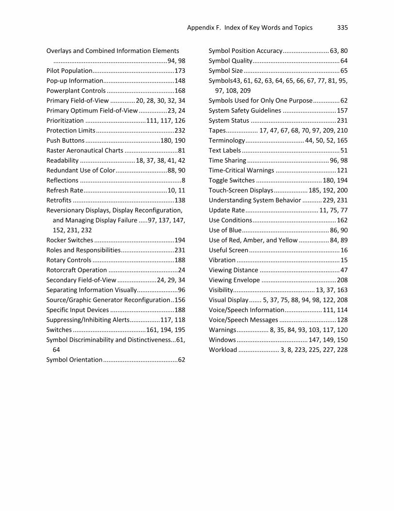
Appendix F. Index of Key Words and Topics
335
Overlays and Combined Information Elements ................................................................ 94, 98
Pilot Population .............................................. 173 Pop-up Information........................................ 148 Powerplant Controls ...................................... 168 Primary Field-of-View .............. 20, 28, 30, 32, 34 Primary Optimum Field-of-View ................ 23, 24 Prioritization .................................. 111, 117, 126 Protection Limits ............................................ 232 Push Buttons .......................................... 180, 190 Raster Aeronautical Charts .............................. 81 Readability ............................... 18, 37, 38, 41, 42 Redundant Use of Color ............................. 88, 90 Reflections ......................................................... 8 Refresh Rate ............................................... 10, 11 Retrofits ......................................................... 138 Reversionary Displays, Display Reconfiguration,
and Managing Display Failure ..... 97, 137, 147, 152, 231, 232
Rocker Switches ............................................. 194 Roles and Responsibilities .............................. 231 Rotary Controls .............................................. 188 Rotorcraft Operation ....................................... 24 Secondary Field-of-View ...................... 24, 29, 34 Separating Information Visually ....................... 96 Source/Graphic Generator Reconfiguration .. 156 Specific Input Devices .................................... 188 Suppressing/Inhibiting Alerts ................. 117, 118 Switches ......................................... 161, 194, 195 Symbol Discriminability and Distinctiveness... 61,
64 Symbol Orientation .......................................... 62
Symbol Position Accuracy .......................... 63, 80 Symbol Quality ................................................. 64 Symbol Size ...................................................... 65 Symbols 43, 61, 62, 63, 64, 65, 66, 67, 77, 81, 95,
97, 108, 209 Symbols Used for Only One Purpose ............... 62 System Safety Guidelines .............................. 157 System Status ................................................ 231 Tapes .................. 17, 47, 67, 68, 70, 97, 209, 210 Terminology ................................. 44, 50, 52, 165 Text Labels ....................................................... 51 Time Sharing .............................................. 96, 98 Time-Critical Warnings .................................. 121 Toggle Switches ..................................... 180, 194 Touch-Screen Displays ................... 185, 192, 200 Understanding System Behavior ........... 229, 231 Update Rate ......................................... 11, 75, 77 Use Conditions ............................................... 162 Use of Blue ................................................. 86, 90 Use of Red, Amber, and Yellow ................. 84, 89 Useful Screen ................................................... 16 Vibration .......................................................... 15 Viewing Distance ............................................. 47 Viewing Envelope .......................................... 208 Visibility.............................................. 13, 37, 163 Visual Display ....... 5, 37, 75, 88, 94, 98, 122, 208 Voice/Speech Information ..................... 111, 114 Voice/Speech Messages ................................ 128 Warnings .................. 8, 35, 84, 93, 103, 117, 120 Windows ........................................ 147, 149, 150 Workload ....................... 3, 8, 223, 225, 227, 228
U.S. Department of Transportation John A. Volpe National Transportation Systems Center
55 Broadway Cambridge, MA 02142-1093
(617) 494-2000 www.volpe.dot.gov
DOT-VNTSC-FAA-13-09
DOT/FAA/TC-13/44