Embed Size (px)
Citation preview

Flight-Test Evaluation of Small Form-Factor LiDAR and Radar Sensors for sUAS Detect-and-Avoid
Applications Maarten Uijt de Haag, Chris G. Bartone, Michael S. Braasch
Ohio University Athens, Ohio U.S.A.
Abstract Despite well over a decade of intensive research and
development efforts, detect-and-avoid (DAA) technology remains in an immature state for medium and large unmanned aerial systems (UAS) and is in its very infancy for small UAS (sUAS). Routine Beyond Visual Line-of-Sight (BVLOS) operations will not be achieved until this technological impasse has been surpassed. Although a multi-system/multi-sensor approach is known to be the robust solution, sUAS platforms are challenged to host such an equipment suite in addition to their revenue-generating payload for commercial applications. Recent developments in small form-factor LiDAR and radar sensors may prove to be vital components in the overall DAA solution for sUAS. These types of sensors are being developed primarily for the autonomous ground vehicle market, but may be adapted for UAS applications. This paper documents a series of ground and flight tests conducted to evaluate the performance of both a small form-factor LiDAR and radar sensors. Obstacle detection range versus obstacle size is determined for both sensors in static and dynamic flight modes.
Keywords—component; unmanned aerial systems, detect-and-avoid, LIDAR, radar, seek and avoid, UAS, UAV, drone
I. INTRODUCTION In recent years, UASs of various sizes, shapes, and capabilities have been used within the National Air Space (NAS). Large UASs, historically operated by the DoD, NASA and government border control agencies, often have significant payload and avionics capabilities that can be operated with a high level of sophistication and safety. For these highly capable UASs, beyond visual line-of-sight operation is achieved by a combination of on-board sensors, off-board surveillance systems, and communications links to maintain command and control of the UAS. On the other end of the user spectrum, smaller (i.e., 0.5 to 55lbs) non-commercial consumer grade UASs have become commonplace [1]. These type of UAS are typically low cost and operated for recreational purposes. On 21 June 2016, the FAA released Part 107 of the Federal Aviation Regulations specifying the rules for commercial use of small UAS (sUAS) [2]. Prior to the release of Part 107, commercial operation of sUAS was permitted only through a so-called ‘333 exemption’ process authorized by Section 333 of the FAA Modernization and Reform Act (FMRA) of 2012 [3]. As of 19 July 2016, the FAA reported having granted 5,537 petitions for exemption [4]. Whether operating for recreational or commercial purposes,
routine operation of a sUAS in the NAS is restricted to visual line-of-sight. Under model aircraft rules, 333 exemptions and the new Part 107, the operator on the ground must keep the sUAS within his or her unaided visual line-of-sight (VLOS) even if first person view (FPV) technology is being utilized. The distance at which a sUAS remains ‘in sight’ is obviously a function of the visual acuity of the operator, the size and color of the sUAS, whether or not the sUAS has any high-visibility lighting on it and, finally, the ambient lighting conditions. Consumer quad-copters may be visible up to a few hundred meters and larger sUAS up to a mile approximately [5]. The VLOS restriction of the current sUAS regulations limits commercial applications. Clearly, sUAS-based package delivery will be of little value if the delivery zone is limited to a VLOS radius around the warehouse. Drone delivery company Flirtey made headlines in March 2016 for conducting the first FAA-authorized drone delivery in the United States flown without guidance from a ground operator [6]. Flirtey followed this with a July 2016 delivery of a 7-Eleven slurpee [7]. The first delivery (simulated emergency supplies) was performed over a distance of half a mile and the second delivery was over a distance of approximately one mile. Both were conducted in the FAA-designated Nevada UAS test region. Special coordination with the FAA was required for the flights. Routine operation of UASs for commercial purposes beyond visual line-of-sight (BVLOS) poses a significant challenge to the UAS community and Government regulators. Commercial uses of UAS, besides package delivery, will likely involve applications such as real estate marketing and tax assessment, agriculture monitoring, infrastructure or security monitoring, post-disaster environmental assessment and search-and-rescue, just to name a few. For many of these types of applications, the sUAS system is expected to require fully autonomous and/or BVLOS operation. Fully-autonomous and/or BVLOS operations may only be achieved, however, when the UAS is able to comply with the federal requirements to ‘see’ and avoid other aircraft. Since sUAS operations will largely be performed at low altitudes, this requirement is extended to ‘see and avoid’ obstacles including terrain, vegetation, man-made structures, people and animals.
978-1-5090-2523-7/16/$31.00 ©2016 IEEE 1
Since technically machines cannot ‘see,’ the requirement is rephrased as ‘sense-and-avoid,’ ‘detect-sense-and-avoid’ or simply ‘detect-and-avoid.’ In the remainder of this paper we will provide an overview of the detect-and-avoid problem in sUAS and then will describe two promising candidate technologies: LiDAR and Radar. We will conclude the paper by describing some initial results from flight tests recently conducted on an Ohio University sUAS research platform.
II. DETECT-AND-AVOID The Detect-and-Avoid (DAA) requirement originates with sections 111 and 113 of Part 91 of the Federal Aviation Regulations (FAR). The FARs are part of Title 14 of the Code of Federal Regulations (14 CFR). FAR 91.111 addresses “Operating near other aircraft” and FAR 91.113 addresses “Right-of-way rules.” FAR 91.111 forbids operations “so close to another aircraft as to create a collision hazard” and FAR 91.113 requires that “vigilance shall be maintained by each person operating an aircraft so as to see and avoid other aircraft.” These extremely common sense requirements have proven to be difficult to achieve in UAS. RTCA Special Committee 203 “Unmanned Aircraft Systems (UAS)” was established in 2004 and was sunsetted in 2013 without having achieved its goal of establishing standards, certification criteria and test procedures for, among other things, sense-and-avoid systems [8]. In its place, a new special committee was established with a narrower scope. SC-228 “Minimum Operational Performance Standards for Unmanned Aircraft Systems” is initially focusing only on those UAS that are capable of operating in Class A airspace (i.e., altitudes greater than 18,000 feet above MSL) and the purpose of the DAA subsystem is to enable large military UAS to transition through lower-altitude uncontrolled airspace between the surface and Class A or special use airspace [9]. SC-228 is expecting to release Phase One of the MOPS sometime this year [10]. As described by McDuffee, the SC-228 DAA architecture is expected to involve a combination of ADS-B, transponder surveillance and radar sensors [10]. ADS-B will enable detection of cooperative targets, while radar will enable detection of non-cooperative targets, and transponders will enable surveillance by air traffic control as well as TCAS on the UAS. This is a sensible approach for large UAS since the bulk of their low altitude operations will be in airspace where ADS-B Out will be required after January 1, 2020 [11] and where Mode-C or Mode-S transponders are required today. Thus the vast majority of potentially conflicting aircraft will be cooperative targets and radar is to be used for the relatively rare non-cooperative target. sUAS operations, on the other hand, are anticipated to be conducted routinely among a wide variety of non-cooperative
targets. Potential hazards to sUAS include terrain, vegetation (i.e., trees) and obstacles (man-made structures, antenna masts, wind turbines, telephone and power lines). Zeitlin has also noted that UAS must remain clear of clouds so as to be visible to other aircraft and must avoid hazardous weather for safe operation [12]. Sense-and-avoid workshops conducted in 2009 led to the identification of a number of sub-functions that constitute the sense-and-avoid process [12]:
1. Detect 2. Track 3. Evaluate 4. Prioritize 5. Declare 6. Determine 7. Command 8. Execute
For sUAS, robust performance of just the first sub-function (Detect) by itself is non-trivial. Until recently it was difficult even to obtain detection sensors that could meet the SWAP-C requirements. Although HD video cameras are available today even in smart phones, previous research conducted at Ohio University has shown that the resolution still does not support sufficient detection capability [13]. Research in obstacle sensors and collision avoidance technology for autonomous automobiles has spurred the development of small form-factor LiDAR and radar equipment. Both sensors hold the potential to solve the aforementioned detect sub-function requirement. However, to date there has been little evidence presented in the literature regarding performance, particularly in flight. The remainder of this paper presents the results of a first step toward remedying this situation.
III. METHODOLOGY USING LIDAR
A. Sensor technology Laser range scanners or light detection and ranging (LiDAR) sensors have been used extensively for both navigation, obstacle detection and mapping in ground vehicles and aerial robotics. Two-dimensional (2D) laser scanners have been used extensively in aerial robotics to enable 2D and 3D navigation using 3DOF Simultaneous Localization And Mapping (SLAM) methods [14] or extracted features [15]. Rather than using a 2D laser scanner, one could choose to use sensor that produces a 3D point cloud such as a 3D laser scanner or even a 3D imaging sensors. Examples of the latter are the Swissranger, PMD or the Kinect. In that case, features could be extracted from the resulting 3D point cloud and used for 3D pose estimation and DAA. Popular examples of the former are the Velodyne LiDAR products [16], which have been used for navigation and DAA of various autonomous ground vehicle applications including [18] and [19] and mapping applications such as [20].
2
The LiDAR used in this paper onboard the sUAS is the Velodyne VLP-16 shown in Fig. 1. The VLP-16 consists of 16 separate laser rangers that cover a vertical field of view (FoV) of 300 (-150 to 150), have a measurement range of ~100m and a range accuracy of +/- 3cm, and rotate at rates up to 20Hz (i.e., a horizontal FoV of 3600). This results in a data rate of up to 0.3 million points/s. The angular resolutions are 20 in the vertical direction and 0.10 – 0.40 in the azimuth direction [17]. With a weight of ~800g and a high price-tag, this may not the preferred solution for commercial products, but nevertheless a good sensor to evaluate the performance of such a sensor for DAA.
Fig. 1. Velodyne VLP-16 LiDAR unit [17].
The advantages of the LiDAR sensor are it high ranging accuracy and high update rate enabling accurate estimates of the targets position and velocity within the FoV of the LiDAR. The LiDAR’s limited range and vertical FoV, its large weight and large vertical angular resolution, are clear disadvantages of this technology. However, future technology improvements and different installation configurations may mitigate these disadvantages.
B. Data processing approach TheVLP-16 LiDAR makes up to 0.3 million/point observations per second within its FoV and maximum operating range. Each point is defined by its coordinate w.r.t. the sensor, and the result of the reflection of one of the laser beams off an object. These objects can be:
A. Fixed objects such as buildings, trees and brushes, or B. Dynamic objects such as people, cars and other sUAS.
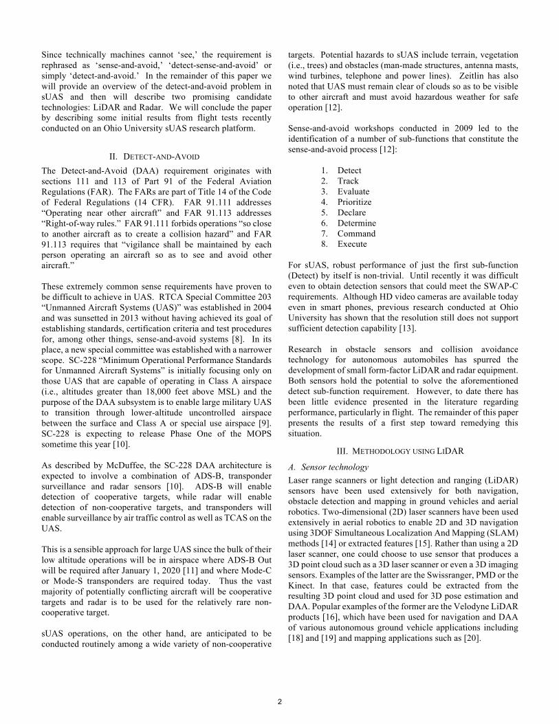
In a LiDAR-based DAA method for sUAS operating at low altitudes, possibly near buildings, both fixed and dynamic objects should be detected and avoided. This paper will focus on the latter. Fig. 2 shows the block of the LiDAR-based DAA method. First, all point cloud measurements belonging to one LiDAR scan (~0.1s) are extracted, and if necessary, compensated for platform motion in the 0.1s scanning interval using the navigation outputs. Next, features-of-interest are extracted from the extracted scan. Features of interest may be surfaces (from buildings or cars), foliage (e.g., trees, brush), people, or other sUAS (represented by clusters of points unconnected from the environment). To enable real-time implementation of the method, any information regarding the features must be
taken into account as the amount of point data is large and would otherwise require a significant data processing. Various libraries exist to manipulate point cloud data such as the PointCloud library [21]. Alternative methods could include methods that make use of 3D occupancy grids. After the feature extractions, these features are associated with previous features (stored in the archive), classified and stored with their time-tags and their relative reference locations and orientations in the feature archive to maintain a time history of these features.
Fig. 2. LiDAR-based DAA method functional block diagram.
Using the feature time series and the sUAS navigation and attitude state, moving features can be identified and input to a tracking algorithm that estimated the target’s trajectory and velocity. Finally, the targets’ position and velocity estimates can be used to assess if loss-of-separation is going to occur and, if so, an avoidance maneuver must be computed. Details on the algorithm is outside the scope of this particular paper. The results section will show results from steps (1) through (3). Note that the extracted feature or the scan as a whole could be used for other functions at the same time, such as navigation and mapping.
IV. METHODOLOGY USING RADAR
A. Sensor technology Radar senor technologies have some key advantages for object detection to support UAS DAA applications. Like LiDAR, radar does not require the cooperation of the object to be detected (as is the case with a cooperative ATC secondary radar systems or ADS-B). Another advantage radar has is the ability to detect objects in the presence of rain, fog, mist, snow, and dust, which is a major limitation of LiDAR type technology. While the longer wavelength of radar, as compared to LiDAR, does provide better propagation through moisture and dust, this longer wavelength does typically produce less range accuracy and azimuth accuracy than LiDAR. For a given radar system, the range accuracy is typically determined by the radar waveform, while the azimuth accuracy is often a function of the antenna configuration. Depending upon the radar frequency and
(1) Extract LiDAR Scan
(2) Extract Distinct Features from Scan
(3) Associate, Classify and Archive Extracted Features Feature Archive
(4) Identify Moving Objects-of-Interest
LiDAR points
Navigation, Mapping, Etc.
Other purposes:
(5) Tracking of MovingObjects
(6) Assess Loss-of-separation and Avoidance Maneuvers
Platform position and attitude
3

antenna configuration, broad antenna beamwidths may provide advantages for UAS DAA applications; however, a scanning LiDAR can also provide comparable coverage.
Historically, high-end airborne radar systems have been large, heavy, and consume significant power. For most aircraft and helicopter systems, these radars are supported by the aircraft power and their capabilities are matched for the application at hand without major integration problems. These large types of airborne radars are believed to be beyond the scope for sUAS commercial small/medium (0.5-55 lbs) BVLOS application.
At the lower end of the radar cost and complexity trade-off equation, we find more consumer oriented radars that have been applied to the automotive industry. With the cost sensitive nature of the automotive industry, these type of low-cost (i.e., about $2k USD) sensors use a continuous wave frequency modulated (CWFM) waveform and architecture for simplicity and cost savings. For lane-keeping and side obstruction detection, 24 GHz radars have become very popular in modern cars [23]. These types of 24 GHz CWFM radars are short range (e.g., 4 meters) and have relatively large beamwidths (e.g., 60 deg) so that a car can be detected in an adjacent lane to warn the driver if the vehicle changes lanes. For adaptive cruise control (ACC) applications, a forward looking radar with a narrower beamwidth is required so that only the vehicle in front of the ACC radar is detected [24]. For these ACC applications, a high frequency of 77 GHz enables narrow beamwidths (e.g., 1 deg) and operating ranges on the order of 100m looking forward in the driver’s lane to detect obstacles of various sizes and compositions [25]. While it may be possible for these automotive type radar sensors to be adapted for sUAS applications, constraints due to frequency allocation and adaptability pose significant hurdles.
The sUAS DAA application imposes some challenges on the radar sensors: they must be lightweight, low cost, small volume, and operate in a dynamic environment. Furthermore, rather than only looking forward, the radar must have a wide enough field of view so that other moving vehicles (e.g., aircraft, other UASs) can be detected and avoided. This wide field of view can be achieved by either a wider antenna beamwidth, or a moving or scanning antenna subsystem.
With regard to the operational range of the sUAS radar sensor, the maximum operating range is expected to be different dependent on the dynamics of the sUAS. The ability of rotor-type sUAS to stop and re-plan their trajectory rapidly, allows the radar sensor to operate over a shorter range, whereas fixed wing and larger sUAS will likely need radar sensor with longer operational ranges. Depending upon the sUAS configuration, the operation range required may vary from several 10’s of meters (i.e., for smaller rotor type sUAS) to several nmi (for larger, less dynamic UASs). However, as the operational range requirements continue to be refined, due consideration should also be given to the operational environment, including the dynamics of a potential target (e.g., aircraft, rotorcraft, fixed obstructions).
The scope of the radar sensor investigations in this paper concentrates on smaller rotor-type sUASs that can very rapidly control their dynamics. Thus, operational ranges are anticipated to be less than 50m or so.
With the challenges in the sUAS radar DAA application, there are few commercially available radars that meet this demand. After a review of the marketplace, we decided to investigate the use of a small reconcilable radar that could be used to research the sUAS DAA application. With cost, size, complexity and weight a major consideration, it was believed that a CWFM based radar would be best suited for the sUAS DAA application. Before the implementation could be achieved, frequency allocation had to be investigated.
B. Frequency Allocation While many avionic systems specifications have been developed in cooperation with the FAA and the aviation community using the RTCA, recent UAS efforts within RTCA have concentrated on large scale, more aircraft-like UAS and their integration into the NAS [26]. RTCA White papers have been published for both Command and Control data link and the DAA aspects for UAS.
Guidance for an appropriate radar frequency band for sUAS applications was also sought through International Telecommuncations Union, Radiocommunication Sector of ITU [27], regarding spectrum considerations for this sUAS DAA application. The ITU-R provides several legacy aviation radar bands used to support aeronautical radionavigation services (ARNS) for three general categories: airborne radars (Table 3, [27], ground-based radars Table 4, [27], and other ARNS allocations (Table 5, [27]). Excluding the ground radar band for consideration, the primary bands for the sUAS DAA application were determined to be 9.300-9.500 GHz and 13.250-13.400 GHz bands. Upon further review of ITU-R pertaining to the 8.500-10.10.689 GHz band, [28], it was noted that there is some precedence for the operation of CWFM radars in this band. With the desire for a CWFM transmission waveform architecture, a review of the manual of regulations and procedures for federal radio frequency management [29], and the availability of prototype hardware in the marketplace, it was decided to concentrate on the airborne 9.300-9.500 GHz band for this sUAS DAA application research project.
To operate in this 9.300-9.500 GHz frequency band requires approval by the Federal Communications Commission (FCC). Authorization was sought for an experimental license under the Special Temporary Authority (STA) Application [30], and granted by the FCC [31].
C. Radar sensor technology implementation With the sUAS DAA radar sensor requirement identified, the selection of a small radar sensor was made. With the requirement for lightweight, low cost, small volume, operation in the 9.300-9.500 GHz airborne frequency band with a CWFM waveform architecture in a dynamic sUAS environment, a commercially available moderately low-cost software configurable radar (SCR) was selected for modification. The core of the radar sensor systems is the Ancortek SDR-980 that was modified for selectable frequencies and bandwidths to form the OU-SCR-940. Standard gain horn antennas were added to provide for 15 dBil of gain for increased operational range. Table I lists some of the key parameters for the radar system, where the selection is done in software (SW) or hardware (HW). The radar has separate transmitter and receiver RF ports to allow for two separate antennas co-located on the platform. These
4

antennas can be configured for vertical or horizontal polarization.
TABLE I. SELECTABLE OPERATIONAL PARAMETERS FOR THE OHIO UNIVERSITY OU-SCR-940 RADAR
Fig. 3 is a functional block diagram of the OU-SCR-940 radar sensor, based on the Ancortek SDR-980. The radar is configured and test conditions are set up with a PC via a USB. Currently, the graphical user interface (GUI) runs under Windows 7 Pro to collect the data in real-time. For these sUAS operations, a small form factor Nano-F43 Polywell PC was used that had dual-core Intel i5 and 16 GB of RAM with 128 GB solid state drive (SSD). The relatively large RAM requirement was based on the current data collection method.
Fig. 3. Block diagram of OU-SCR-940 for sUAS applications [32].
Table 2 provides the size and weight of each of the major components of the radar sensor.
Radar in-phase (I) and quadrature (Q) data was collected in real-time and after data collection was complete, the data was written to the SSD in ASCII format. The I & Q data was then post processed in Matlab® to produce data plots in various formats suitable for performance analysis.
TABLE II. SIZE AND WEIGHT FOR MAJOR COMPONENT OF THE OHIO UNIVERSITY OU-SCR-940 RADAR SENSOR
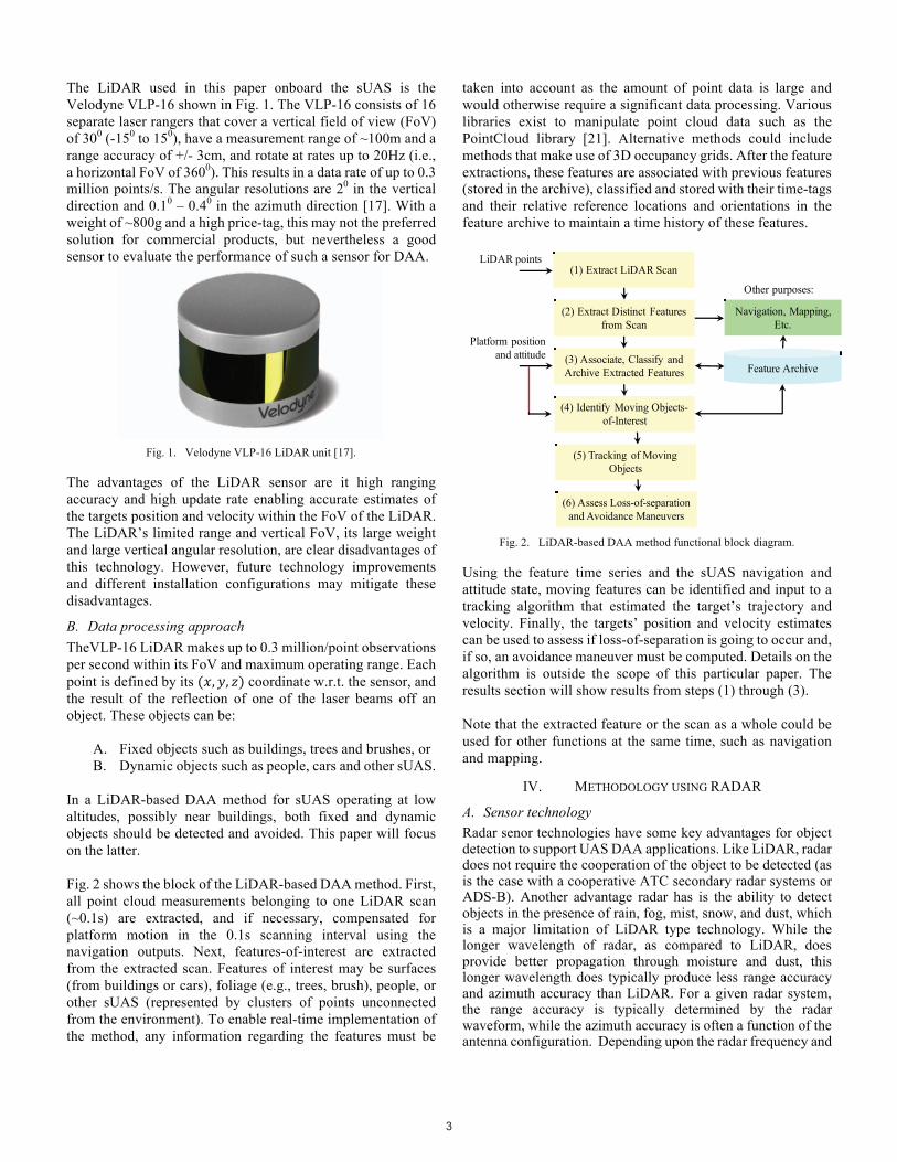
V. SUAS PLATFORM SETUP To evaluate the sensor technologies and methodologies described in sections 3 and 4, data was collected using an octocopter (X8). The basic frame of these platforms was purchased as a kit and then modified to accommodate the LiDAR and RADAR payloads required for this research. Fig. 4 and Fig. 5 show the Octocopter with the RADAR and LiDAR payload installed, respectively. The designed multi-copter has already demonstrated the capability of flying both indoors and outdoors while collecting laser, GPS, inertial, barometric, and digital imagery data [22]. Flight control of the X8 is managed by a Pixhawk flight controller connected to both the embedded processor and the manual flight controller. Fig. 4 shows a photograph of the radar equipped X8 sUAS. The transmitter and receiver horn antennas can be seen to the right (oriented for horizontal polarization). For the initial tests, the radar antennas were mounted to the sUAS frame. The radar sensor module can be partially seen on the bottom rear end of the X8 (small light blue box). The radar PC is located on top of the sUAS, which can be remotely accessed via WiFi.
Fig. 4. sUAS platform: Octocopter with OU-SCR-940 installed.
Fig. 5 shows the X8 equipped with the Velodyne LiDAR sensor installed in a horizontal manner. The LiDAR is interfaced to an onboard embedded processor, an Odroid XU4, which runs the Robotic Operating System (ROS) on an Ubuntu operating system. For diagnostic purposes and communication with each of the sensors during flight, an 802.11b wireless connection is established between the embedded processor and a ground station. During data collections, all of the desired sensor data is recorded on the embedded processor stored in "rosbags", and
5
then offloaded to the ground station where ROS and Matlab® are used to analyze the data.
Fig. 5. sUAS platform: Octocopter with Velodyne VLP16 Puck installed.
VI. FLIGHT TEST RESULTS
A. RADAR 1) Baseline Radar Performance
To establish a baseline performance for the radar sensor, the radar sensor was kept static on the ground with a radar cross section (RCS) enhanced X8 (RCS e-X8) sUAS target platform. The RCS of the target X8 sUAS was enhanced with a 6 inch diameter aluminum sphere to help ensure a known minimum RCS of the target, regardless of the aspect angle. With the radar operating anywhere in the 9.300-9.500 GHz band the RCS of the sphere is characterized in the optical region [33]. Thus, the RCS of the sphere can be calculated as 0.0182 m2 for the radar operating at 9.400 GHz.
The purpose of these baseline tests was to investigate the radar’s range and azimuth performance in a less dynamic environment with only the target RCS e-X8 sUAS in flight and the radar static. The radar sensor was placed on a plastic cart, 1m off the ground with the transmitter and receiver RF horn antennas separated by approximately 8 inches (similar to the mounting configuration on the X8 sUAS).
The target RCS e-X8 sUAS flew at a height of approximately 8m above ground with a flight profile during which the range between radar and target was continuously increased then decreased (in-and-out flight profile). While the target RCS e-X8 was generally in front of the radar sensor, the target wandered left and right (in azimuth) over approximately a 10m range.
Data was collected at a frequency of 9.400 GHz in a CWFM mode over a bandwidth of 200 MHz, with a frequency sweep time of 1ms where 1024 samples were taken every 1ms sweep, for a total duration of 600s. After data collection was complete the data was post-processed in Matlab®. In real-time, data was collected and displayed where the performance of the radar was assessed with respect to polarization of the radar antenna configuration.
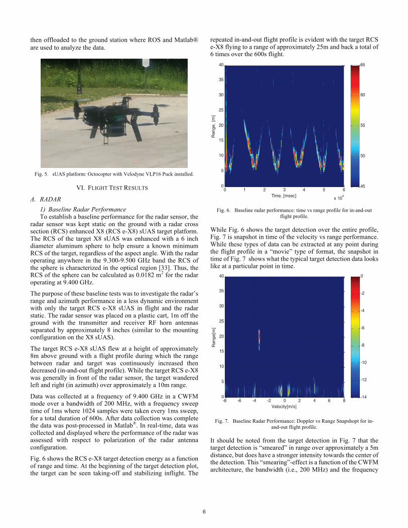
Fig. 6 shows the RCS e-X8 target detection energy as a function of range and time. At the beginning of the target detection plot, the target can be seen taking-off and stabilizing inflight. The
repeated in-and-out flight profile is evident with the target RCS e-X8 flying to a range of approximately 25m and back a total of 6 times over the 600s flight.
Fig. 6. Baseline radar performance: time vs range profile for in-and-out
flight profile.
While Fig. 6 shows the target detection over the entire profile, Fig. 7 is snapshot in time of the velocity vs range performance. While these types of data can be extracted at any point during the flight profile in a “movie” type of format, the snapshot in time of Fig. 7 shows what the typical target detection data looks like at a particular point in time.
Fig. 7. Baseline Radar Performance: Doppler vs Range Snapshopt for in-
and-out flight profile.
It should be noted from the target detection in Fig. 7 that the target detection is “smeared” in range over approximately a 5m distance, but does have a stronger intensity towards the center of the detection. This “smearing”-effect is a function of the CWFM architecture, the bandwidth (i.e., 200 MHz) and the frequency
Time, [msec]
Range,
[m]
0 1 2 3 4 5 6
x 104
0
5
10
15
20
25
30
35
40
45
50
55
60
65
Velocity[m/s]
Range[m
]
-8 -6 -4 -2 0 2 4 6 80
5
10
15
20
25
30
35
40
-14
-12
-10
-8
-6
-4
-2
0
6
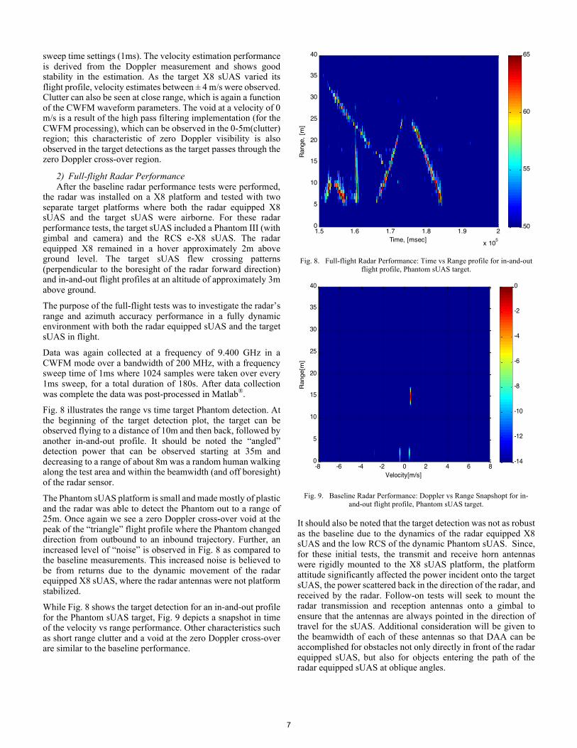
sweep time settings (1ms). The velocity estimation performance is derived from the Doppler measurement and shows good stability in the estimation. As the target X8 sUAS varied its flight profile, velocity estimates between ± 4 m/s were observed. Clutter can also be seen at close range, which is again a function of the CWFM waveform parameters. The void at a velocity of 0 m/s is a result of the high pass filtering implementation (for the CWFM processing), which can be observed in the 0-5m(clutter) region; this characteristic of zero Doppler visibility is also observed in the target detections as the target passes through the zero Doppler cross-over region.
2) Full-flight Radar Performance After the baseline radar performance tests were performed, the radar was installed on a X8 platform and tested with two separate target platforms where both the radar equipped X8 sUAS and the target sUAS were airborne. For these radar performance tests, the target sUAS included a Phantom III (with gimbal and camera) and the RCS e-X8 sUAS. The radar equipped X8 remained in a hover approximately 2m above ground level. The target sUAS flew crossing patterns (perpendicular to the boresight of the radar forward direction) and in-and-out flight profiles at an altitude of approximately 3m above ground.
The purpose of the full-flight tests was to investigate the radar’s range and azimuth accuracy performance in a fully dynamic environment with both the radar equipped sUAS and the target sUAS in flight.
Data was again collected at a frequency of 9.400 GHz in a CWFM mode over a bandwidth of 200 MHz, with a frequency sweep time of 1ms where 1024 samples were taken over every 1ms sweep, for a total duration of 180s. After data collection was complete the data was post-processed in Matlab®.
Fig. 8 illustrates the range vs time target Phantom detection. At the beginning of the target detection plot, the target can be observed flying to a distance of 10m and then back, followed by another in-and-out profile. It should be noted the “angled” detection power that can be observed starting at 35m and decreasing to a range of about 8m was a random human walking along the test area and within the beamwidth (and off boresight) of the radar sensor.
The Phantom sUAS platform is small and made mostly of plastic and the radar was able to detect the Phantom out to a range of 25m. Once again we see a zero Doppler cross-over void at the peak of the “triangle” flight profile where the Phantom changed direction from outbound to an inbound trajectory. Further, an increased level of “noise” is observed in Fig. 8 as compared to the baseline measurements. This increased noise is believed to be from returns due to the dynamic movement of the radar equipped X8 sUAS, where the radar antennas were not platform stabilized.
While Fig. 8 shows the target detection for an in-and-out profile for the Phantom sUAS target, Fig. 9 depicts a snapshot in time of the velocity vs range performance. Other characteristics such as short range clutter and a void at the zero Doppler cross-over are similar to the baseline performance.
Fig. 8. Full-flight Radar Performance: Time vs Range profile for in-and-out
flight profile, Phantom sUAS target.
Fig. 9. Baseline Radar Performance: Doppler vs Range Snapshopt for in-
and-out flight profile, Phantom sUAS target.
It should also be noted that the target detection was not as robust as the baseline due to the dynamics of the radar equipped X8 sUAS and the low RCS of the dynamic Phantom sUAS. Since, for these initial tests, the transmit and receive horn antennas were rigidly mounted to the X8 sUAS platform, the platform attitude significantly affected the power incident onto the target sUAS, the power scattered back in the direction of the radar, and received by the radar. Follow-on tests will seek to mount the radar transmission and reception antennas onto a gimbal to ensure that the antennas are always pointed in the direction of travel for the sUAS. Additional consideration will be given to the beamwidth of each of these antennas so that DAA can be accomplished for obstacles not only directly in front of the radar equipped sUAS, but also for objects entering the path of the radar equipped sUAS at oblique angles.
Time, [msec]
Ran
ge,
[m]
1.5 1.6 1.7 1.8 1.9 2
x 105
0
5
10
15
20
25
30
35
40
50
55
60
65
Velocity[m/s]
Range[m
]
-8 -6 -4 -2 0 2 4 6 80
5
10
15
20
25
30
35
40
-14
-12
-10
-8
-6
-4
-2
0
7
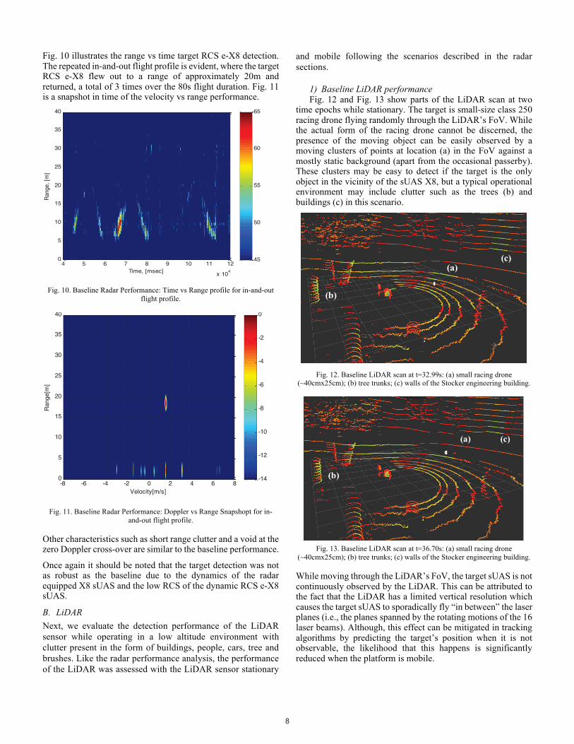
Fig. 10 illustrates the range vs time target RCS e-X8 detection. The repeated in-and-out flight profile is evident, where the target RCS e-X8 flew out to a range of approximately 20m and returned, a total of 3 times over the 80s flight duration. Fig. 11 is a snapshot in time of the velocity vs range performance.
Fig. 10. Baseline Radar Performance: Time vs Range profile for in-and-out
flight profile.
Fig. 11. Baseline Radar Performance: Doppler vs Range Snapshopt for in-
and-out flight profile.
Other characteristics such as short range clutter and a void at the zero Doppler cross-over are similar to the baseline performance.
Once again it should be noted that the target detection was not as robust as the baseline due to the dynamics of the radar equipped X8 sUAS and the low RCS of the dynamic RCS e-X8 sUAS.
B. LiDAR Next, we evaluate the detection performance of the LiDAR sensor while operating in a low altitude environment with clutter present in the form of buildings, people, cars, tree and brushes. Like the radar performance analysis, the performance of the LiDAR was assessed with the LiDAR sensor stationary
and mobile following the scenarios described in the radar sections.
1) Baseline LiDAR performance Fig. 12 and Fig. 13 show parts of the LiDAR scan at two time epochs while stationary. The target is small-size class 250 racing drone flying randomly through the LiDAR’s FoV. While the actual form of the racing drone cannot be discerned, the presence of the moving object can be easily observed by a moving clusters of points at location (a) in the FoV against a mostly static background (apart from the occasional passerby). These clusters may be easy to detect if the target is the only object in the vicinity of the sUAS X8, but a typical operational environment may include clutter such as the trees (b) and buildings (c) in this scenario.
Fig. 12. Baseline LiDAR scan at t=32.99s: (a) small racing drone
(~40cmx25cm); (b) tree trunks; (c) walls of the Stocker engineering building.
Fig. 13. Baseline LiDAR scan at t=36.70s: (a) small racing drone
(~40cmx25cm); (b) tree trunks; (c) walls of the Stocker engineering building.
While moving through the LiDAR’s FoV, the target sUAS is not continuously observed by the LiDAR. This can be attributed to the fact that the LiDAR has a limited vertical resolution which causes the target sUAS to sporadically fly “in between” the laser planes (i.e., the planes spanned by the rotating motions of the 16 laser beams). Although, this effect can be mitigated in tracking algorithms by predicting the target’s position when it is not observable, the likelihood that this happens is significantly reduced when the platform is mobile.
Time, [msec]
Ran
ge, [
m]
4 5 6 7 8 9 10 11 12
x 104
0
5
10
15
20
25
30
35
40
45
50
55
60
65
Velocity[m/s]
Ran
ge[m
]
-8 -6 -4 -2 0 2 4 6 80
5
10
15
20
25
30
35
40
-14
-12
-10
-8
-6
-4
-2
0
(a)
(b)
(c)
(a)
(b)
(c)
8

2) Mobile LiDAR performance Next, multiple scenarios were executed in which both the sUAS X8 and the target sUAS (the Phantom III) are moving. In scenario 1 the target flies away from the X8 at constant altitude. In scenario 2, the target crosses the path of the X8 at various altitudes.
Fig. 14 shows a sequence from scenario 1. Similar to the stationary case, the target can be clearly observed as a cluster of pixels rather than a clear form sUAS. Again, structured features such as building, parked trucks and the road can also be observed and easily extracted.
Fig. 14. Sequence of LiDAR scans (multiple seconds apart).
When tracking the target sUAS while flying away from the X8 in scenario 1, the target can be detected with a high probability for ranges smaller than 15m, however, beyond that range the detection probability decreases due to the increased probability
that the target flies “in between” the laser scans and because the target becomes optically small at that range. Fig. 15 and Fig. 16 show the detected target at close range and longer range, respectively.
Fig. 15. Target sUAS flying away from X8 equipped with LiDAR: target is easily detected even in a clutter environment.
Fig. 16. Target sUAS flying away from X8 equipped with LiDAR: target at larger distance has a lower probability of detection.
In the second scenario, the target sUAS crosses the intended direction of the X8. For this scenario the data was processed following the methods proposed in Section III.A. Some preliminary results are shown in Fig. 17. As only limited motion
compensation has been applied solely based only on the LiDAR data, target trajectory estimation noise on the order of dm’s can be observed. However, based on the results in Fig. 17, it is expected that with (i) improved motion compensation by using
-20 -10 0 10 20 30 40 50 60
x [m]
-20
-15
-10
-5
0
5
10
15
20
y [m
]
LiDAR Point Cloud - #311
-20 -10 0 10 20 30 40 50 60
x [m]
-20
-15
-10
-5
0
5
10
15
20
y [m
]
LiDAR Point Cloud - #398
9
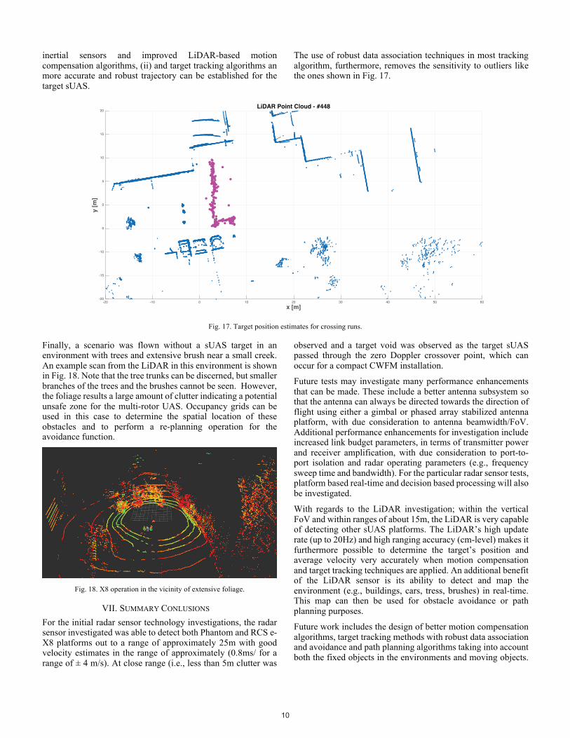
inertial sensors and improved LiDAR-based motion compensation algorithms, (ii) and target tracking algorithms an more accurate and robust trajectory can be established for the target sUAS.
The use of robust data association techniques in most tracking algorithm, furthermore, removes the sensitivity to outliers like the ones shown in Fig. 17.
Fig. 17. Target position estimates for crossing runs.
Finally, a scenario was flown without a sUAS target in an environment with trees and extensive brush near a small creek. An example scan from the LiDAR in this environment is shown in Fig. 18. Note that the tree trunks can be discerned, but smaller branches of the trees and the brushes cannot be seen. However, the foliage results a large amount of clutter indicating a potential unsafe zone for the multi-rotor UAS. Occupancy grids can be used in this case to determine the spatial location of these obstacles and to perform a re-planning operation for the avoidance function.
Fig. 18. X8 operation in the vicinity of extensive foliage.
VII. SUMMARY CONLUSIONS For the initial radar sensor technology investigations, the radar sensor investigated was able to detect both Phantom and RCS e-X8 platforms out to a range of approximately 25m with good velocity estimates in the range of approximately (0.8ms/ for a range of ± 4 m/s). At close range (i.e., less than 5m clutter was
observed and a target void was observed as the target sUAS passed through the zero Doppler crossover point, which can occur for a compact CWFM installation.
Future tests may investigate many performance enhancements that can be made. These include a better antenna subsystem so that the antenna can always be directed towards the direction of flight using either a gimbal or phased array stabilized antenna platform, with due consideration to antenna beamwidth/FoV. Additional performance enhancements for investigation include increased link budget parameters, in terms of transmitter power and receiver amplification, with due consideration to port-to-port isolation and radar operating parameters (e.g., frequency sweep time and bandwidth). For the particular radar sensor tests, platform based real-time and decision based processing will also be investigated.
With regards to the LiDAR investigation; within the vertical FoV and within ranges of about 15m, the LiDAR is very capable of detecting other sUAS platforms. The LiDAR’s high update rate (up to 20Hz) and high ranging accuracy (cm-level) makes it furthermore possible to determine the target’s position and average velocity very accurately when motion compensation and target tracking techniques are applied. An additional benefit of the LiDAR sensor is its ability to detect and map the environment (e.g., buildings, cars, tress, brushes) in real-time. This map can then be used for obstacle avoidance or path planning purposes.
Future work includes the design of better motion compensation algorithms, target tracking methods with robust data association and avoidance and path planning algorithms taking into account both the fixed objects in the environments and moving objects.
-20 -10 0 10 20 30 40 50 60
x [m]
-20
-15
-10
-5
0
5
10
15
20
y [m
]
LiDAR Point Cloud - #448
10

Finally, a second set of flights test is envisioned in which the X8 and the target are both be equipped with GNSS reference received for a better truth reference for the trajectory, and, in which, we will vary the orientation (with or without a gimbal) of the sensors on the platform.
VIII.ACKNOWLEDGEMENTS The authors would like to thank Adam Schultz, Russell
Gilabert and Akshay Bharadwaj for their help during the design and flight test stages. The work presented in this paper was partially supported and funded by Honeywell, Inc.
REFERENCES
[1] Shen, L., “Drone Sales Have Tripled in the Last Year,” Fortune.com, May 25, 2016, Accessed: 27July2016.
[2] Federal Aviation Administration, “Fact Sheet – Small Unmanned Aircraft Regulations (Part 107),” https://www.faa.gov/news/fact_sheets/news_story.cfm?newsId=20516, Accessed: 27July2016.
[3] FMRA excerpt, Subtitle B – Unmanned Aircraft Systems, Sections 331 – 336, https://www.faa.gov/uas/media/Sec_331_336_UAS.pdf; Accessed: 27July2016.
[4] Federal Aviation Administration, “Section 333,” https://www.faa.gov/uas/getting_started/fly_for_work_business/beyond_the_basics/section_333/, Accessed: 27July2016.
[5] Australian Certified UAV Operators, “How do we see them: VLOS, EVLOS, BVLOS & FPV,” http://www.acuo.org.au/industry-information/terminology/how-do-we-see-them/; Accessed: 27Jul2016.
[6] Sonner, S., “For first time, drone delivers package to a residential area” U.S. News & World Report, 25Mar2016, http://www.usnews.com/news/business/articles/2016-03-25/for-first-time-drone-delivers-package-to-residential-area; Accessed 27July2016.
[7] Vanian, J., “7-Eleven Just Used a Drone to Deliver a Chicken Sandwich and Slurpees,” Fortune.com, 22July2016, http://fortune.com/2016/07/22/7-eleven-drone-flirtey-slurpee/; Accessed: 27July2016.
[8] Egan, P., “RTCA SC-203 Folds Up,” SUASNEWS.com, 05June2013, http://www.suasnews.com/2013/06/rtca-sc-203-folds-up/; Accessed: 27July2016.
[9] Carey, B., “New RTCA Committee Seeks to Expedite UAS Standards,” AINOnline.com, 05Apr2013, http://www.ainonline.com/aviation-news/2013-04-05/new-rtca-committee-seeks-expedite-uas-standards; Accessed: 27July2016.
[10] McDuffee, P., “Unmanned Aircraft System (UAS) Standards Development, RTCA SC-228 Status,” ICAO Remotely Piloted Aircraft Systems (RPAS) Symposium 2015, Montreal, Canada, March 2015.
[11] Federal Aviation Administration, “ADS-B Frequently Asked Questions (FAQs),” https://www.faa.gov/nextgen/programs/adsb/faq/; Accessed: 27July2016.
[12] Zeitlin, A., “Progress on Requirements and Standards for Sense & Avoid,” Technica Paper, The MITRE Corporation, August 2010, https://www.mitre.org/publications/technical-papers/progress-on-requirements-and-standards-for-sense--avoid; Accessed: 27July2016.
[13] Kephart, R. and M. Braasch, “Comparison of See-and-Avoid Performance in Manned and Remotely Piloted Aircraft,” 27th Digital Avionics Systems Conference (DASC), St. Paul, MN, October 2008.
[14] E. Dill and M. Uijt de Haag, “3D Multi-Copter Navigation and Mapping Using GPS, Inertial, and LiDAR,” NAVIGATION, Vol. 63, No. 2, 2016.
[15] A. Soloviev and M. Uijt de Haag, “Three-Dimensional Navigation of Autonomous Vehicles Using Scanning Laser Radars: Concept and Initial
Verification,” IEEE Transactions on Aerospace and Electronic Systems, Vol. 46, Issue 1, 2010.
[16] www.velodynelidar.com, accessed in August 2016. [17] Velodyne, VLP-16 – Velodyne LiDAR PUCK Datasheet, 2016. [18] C. Urmson et al., “Autonomous driving in urban environments: Boss and
the Urban Challenge,” Journal of Field Robotics Special Issue on the 2007 DARPA Urban Challenge Vol. 25, Issue. 8, pp. 425–466, 2008.
[19] L. Nissen and K. Greenberg, “With Deft Approach Shot from Velodyne's VLP-16 LiDAR Puck, SMART Deploys Self-Driving Golf Carts in Singapore,” April 2016.
[20] Unmanned Systems News, “XactSense Develops New UAV Mapping Platform Incorporating Velodyne LiDAR,” March 2015.
[21] Rusu, R. B. and S. Cousins, “3D is here: Point Cloud Library (PCL),” Proc. of IEEE International Conference on Robotics and Automation (ICRA), 2011.
[22] E. Dill, M. Uijt de Haag, D. Serrano, S. Vilardaga, P. Duan, “Seamless Indoor-Outdoor Navigation for Unmanned Multi-Sensor Aerial Platforms,” Proceedings of IEEE/ION PLANS 2014, May 5-8, 2014.
[23] Infineon, 24GHz Radar-Automotive, http://www.infineon.com/cms/en/product/rf-and-wireless-control/mm-wave-mmic/24-ghz-radar-automotive/channel.html?channel=5546d4624f205c9a014f465e853c277c, date visited July 20, 2016.
[24] Bosch, Bosch Mobility Solutions, Driver assistance systems - Adaptive cruise control (ACC), http://products.bosch-mobility-solutions.com/en/de/_technik/component/CO_PC_DA_Adaptive-Cruise-Control_CO_PC_Driver-Assistance_2434.html?compId=2496, date visited July 20, 2016.
[25] Komarabathuni, Ravi. "Performance Assessment of a 77 GHz Automotive Radar for Various Obstacle Avoidance Application." Electronic Thesis or Dissertation. Ohio University, 2011. OhioLINK Electronic Theses and Dissertations Center. 21 Jul 2016. https://etd.ohiolink.edu/ap/10?0::NO:10:P10_ACCESSION_NUM:ohiou1304083389, date visited July 21, 2016.
[26] RTCA, Minimum Operational Performance Standards for Unmanned Aircraft Systems, SC-228, www.rtca.org
[27] International Telecommuncations Union, Radiocommunication Sector of ITU, Report ITU-R M.2204 (11/2010), Characteristics and protection criteria for terrestrial radars operating in the radiodetermination service in the frequency band 8 500-10 6800 MHz, M Series, Mobile, radiodetermination, amateur and related satellites services.
[28] International Telecommuncations Union, Radiocommunication Sector of ITU, Report ITU-R M.1796-2 (02/2014), Characteristics and spectrum considerations for sense and avoid systems use on unmanned aircraft systems, M Series, Mobile, radiodetermination, amateur and related satellites services.
[29] U.S. Department of Commerce, National Telecommunciations and Information Administration, Manual of Regulations and Procedures for Federal Radio Frequency Management, May 2014 Revision of the May 2013 Edition, https://www.ntia.doc.gov/files/ntia/publications/redbook/2014-05/Manual_2014_Revision.pdf
[30] Bartone, C., Ohio University Special Temporary Authority Application, FRN Number: 0025370479,STA Confirmation Number: EL822103, STA File Number: 0315-EX-ST-2016, Date of Submission: March 8, 2016
[31] Federal Communications Commission, United States of America, Experimentatl Specical Temporty Authorization, Call Sign: WJ9XOE, File Number: 0315-EX-ST-2016, dated April 4, 2016.
[32] Ancortek, http://ancortek.com/sdr-kit-980b, visited July 21, 2016. [33] Peebles, Peyton Z., Radar Principles, John Wiley & Sons, Inc., ISBN: 0-
471-25205-0, 1998, pp. 197-199.
11