Embed Size (px)
Citation preview

1
Ophélia Bolmin Céline Lay Fanny Risbourg
Louis le Grand High School
2012 EUCYS
HEXAPEDAL ROBOT

HEXAPEDAL ROBOT –France– 2012 EUCYS
2
Acknowledgements:
We wish to thank Christian Garreau for his excellent advice
and continued support throughout our project, our teacher
Fabrice Boisneau and Paul Birkmeyer, a researcher at Berkeley
University’s Biomimetic Millisystems Laboratory in the United
States, for their invaluable and enthusiastic support which was
instrumental to the successful completion of our project. We also
wish to acknowledge Granville Fields for his valued contribution
to the translations.
We extend a special thanks to our parents and friends for
their patience and support.
Lastly, we thank the C’Génial (It’s Great) Foundation and the
Science à l’Ecole (Science in School) initiative for making it
possible for us take part in the European Union Contest for Young
Scientists.

HEXAPEDAL ROBOT –France– 2012 EUCYS
3
HOW CAN A ROBOT IMITATE A HEXAPOD
AND BE ENERGY EFFICIENT?
CONTENTS
INTRODUCTION: ....................................................................................................................... 4
I. MODELING OF A HEXAPEDAL ROBOT ................................................................... 5
A. OVERVIEW OF THE DYNAMIC HEXAPEDAL ROBOT WITH FLAPPING WINGS
(DASH+WINGS) ....................................................................................................................... 5
B. FROM OBSERVATION TO MODELING ............................................................................... 7
C. FROM MODELING TO DESIGNING A ROBOT ................................................................. 10
D. FROM DESIGNING TO ENGINEERING ............................................................................ 13
II. PERFORMANCES OF THE PROTOTYPE ............................................................... 15
A. GENERAL PRESENTATION .............................................................................................. 15
B. PERFORMANCES OF THE ROBOT ................................................................................... 17
CONCLUSION: ......................................................................................................................... 20

HEXAPEDAL ROBOT –France– 2012 EUCYS
4
INTRODUCTION:
In nature, living beings have characteristics that researchers try to reproduce. In fact,
nature has produced some fairly incredible technical achievements—the result of millions of
years of evolution. If humans take the time to observe nature, they might find viable, reliable and
energy efficient solutions to address problems that they face in daily life. This ability to
reproduce reality is a product of natural intelligence called biomimetics. So, while humans now
use vast quantities of energy to make glass, biomimetics seeks inspiration from glass sponges
that produce ambient temperature in the sea; this glass is significantly more solid that that
produced by man at a cost that comes with a startling carbon footprint.
Since the 1960s, there has been widespread realization and the use of biomimetics has
rapidly expanded: by studying the kingfisher bird, known for its speed when plunging in water,
engineers managed to increase the speed of the Shinkansen (Japan’s high speed bullet train in
service since 1964) while reducing its energy consumption. There is also the Mercedes-Benz
Bionic, a concept car introduced in 2005 and whose exterior design was modeled after the
exoskeleton of the boxfish, a small fish found in the Caribbean Sea that has excellent
hydrodynamic characteristics. Mercedes-Benz’s engineers designed a prototype bionic car that
uses 80% less fuel that most of the cars in its class while, at the same time, increasing the car’s
stability.
When humanitarian crises occur (earthquakes, tsunamis or nuclear accidents), a number
of robots are sent to devastated places inaccessible to humans in order to find victims or to
evaluation damages in high risk areas. These robots are cumbersome, complex, expensive and
require a considerable amount of power.
We therefore decided to design an innovative humanitarian robotic system modeled
after the hexapod and to develop a simple and low-cost prototype that observes the main
constraint of biomimetics: energy efficiency. To do this, we first studied and detailed the
characteristics of the hexapod’s motion and then, using as a starting point a robot that already
exists (DASH + Wings1), we designed a model with a single motor to generate motion. We then
selected materials and components for their light weight to contribute to the robot’s
performance.
Our goal was to answer the following question:
How can a robot imitate a hexapod and be energy efficient?
HEXAPEDAL ROBOT –France– 2012 EUCYS
5
I. MODELING OF A HEXAPEDAL ROBOT
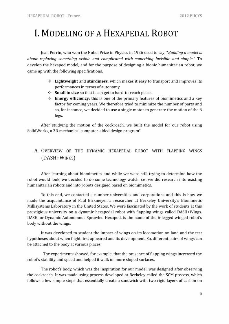
Jean Perrin, who won the Nobel Prize in Physics in 1926 used to say, “Building a model is
about replacing something visible and complicated with something invisible and simple.” To
develop the hexapod model, and for the purpose of designing a bionic humanitarian robot, we
came up with the following specifications:
Lightweight and sturdiness, which makes it easy to transport and improves its
performances in terms of autonomy
Small in size so that it can get to hard-to-reach places
Energy efficiency: this is one of the primary features of biomimetics and a key
factor for coming years. We therefore tried to minimize the number of parts and
so, for instance, we decided to use a single motor to generate the motion of the 6
legs.
After studying the motion of the cockroach, we built the model for our robot using
SolidWorks, a 3D mechanical computer-aided design program2.
A. OVERVIEW OF THE DYNAMIC HEXAPEDAL ROBOT WITH FLAPPING WINGS
(DASH+WINGS)
After learning about biomimetics and while we were still trying to determine how the
robot would look, we decided to do some technology watch, i.e., we did research into existing
humanitarian robots and into robots designed based on biomimetics.
To this end, we contacted a number universities and corporations and this is how we
made the acquaintance of Paul Birkmeyer, a researcher at Berkeley University’s Biomimetic
Millisystems Laboratory in the United States. We were fascinated by the work of students at this
prestigious university on a dynamic hexapedal robot with flapping wings called DASH+Wings.
DASH, or Dynamic Autonomous Sprawled Hexapod, is the name of the 6-legged winged robot’s
body without the wings.
It was developed to student the impact of wings on its locomotion on land and the test
hypotheses about when flight first appeared and its development. So, different pairs of wings can
be attached to the body at various places.
The experiments showed, for example, that the presence of flapping wings increased the
robot’s stability and speed and helped it walk on more sloped surfaces.
The robot’s body, which was the inspiration for our model, was designed after observing
the cockroach. It was made using process developed at Berkeley called the SCM process, which
follows a few simple steps that essentially create a sandwich with two rigid layers of carbon on

HEXAPEDAL ROBOT –France– 2012 EUCYS
6
the outside with flexible polymer inside. In order to make the joints highly flexible, all you have
to do it cut the carbon layers.
Robot DASH + Wings
DASH is a small, quick and lightweight robot that imitates a cockroach. It is very sturdy:
it can withstand falls and is able to clear obstacles. These are the qualities that we wanted to
endow our robot with. We therefore elected to design and verify the performances of a robot
engineered based on the DASH, i.e., it resembles the motion pattern of the cockroach. But in
keeping with the philosophy of biomimetics, our robot will have to be energy efficient, which is
why we used the following process: we observation realty and then built the model.

HEXAPEDAL ROBOT –France– 2012 EUCYS
7
B. FROM OBSERVATION TO MODELING
The cockroach is a small (it is about 4 centimeters long), fast (it moves at an average
speed of 1 meter per second) and lightweight (it weighs no more than 20 grams) hexapod.
We first observed the motion pattern of the cockroach before modeling its motion.
a. b.
c. d.
Figure 3: Motion of a leg during locomotion3
We first noticed that the leg is divided into two segments (in yellow and green in figure 3).
These two segments are in motion in relation to one another. We observed that the leg is always
extended when it touches the floor (a. and c.). We thus did away with the motion of the
second segment in relation to the first by modeling the link between these two segments
with an embedded linkage that has no degree of movement.
Next, we noticed that the motion of this first segment rotates in relation to the
cockroach’s body.
The linkage between the insect’s body and the first segment has
three degrees of freedom: three rotations around axes , and .
(central orthogonal point of reference O featured in the first to the
left).
Repère

HEXAPEDAL ROBOT –France– 2012 EUCYS
8
We first modeled the linkage between the body and the leg with a linking knee
joint (figure 4). This linkage has three degrees of freedom and three rotations.
So the kinematic screw chain of this link, at point A in the orthogonal point of reference
(0, ), is as follows:
{
} {
}
But when observing more closely the motion of the hexapod, we realized that rotation
around the axis is not necessary for the robot to work. So, we did not use a linking
knee joint to model the leg but rather a spherical finger joint linkage (figure 5).
This linkage has two degrees of freedom and two rotations. It is therefore associated
with the following kinematic screw chain of this link, in the orthogonal point of reference (0,
):
{
} {
}
Figure 4: Diagram of a center linking knee joint A
A BODY LEG
Figure 5: Modeling of a leg: Diagram of a center spherical
finger joint linkage A
𝑧 ��
��
𝑧 ��
��
A BODY LEG

HEXAPEDAL ROBOT –France– 2012 EUCYS
9
We then observed the motion of the legs in relation to one another. The motion is
produced by 2 sets of 3 legs moving in rotation. Each of the 2 tripods has a back leg and a front
leg on one side and a center let on the other side.
The motion of the tripods is alternating so only three legs at a time are in contact with
the ground.
a. b.
Figure 6: Position of the tripods during motion
Figure 6 above shows the legs of each tripod circled using the same color. So a. shows
that the yellow tripod is in contact with the group while in b. the green tripod is.
We based our model on the motion of the two tripods with 2 alternating rotations
(Figure 7).
Figure 7: Modeling of the cockroach
BODY

HEXAPEDAL ROBOT –France– 2012 EUCYS
10
C. FROM MODELING TO DESIGNING A ROBOT
Next, we set out to find a technical solution to make our robot. To that end, we used
SolidWorks, a 3D mechanical computer-aided design program The challenge was to find a
solution making it possible to use a single motor and thus a single rotation to create two
alternating motions. This is what makes our robot innovative, while reducing its energy
consumption.
We first sought a leg model that is consistent with this model. The spherical finger joint
linkage has two degrees of freedom and two rotations. So, according to the theory of mechanism
design, this linkage is equivalent to the association of two pivot linkages in parallel. To
make them, we decided to use a cube whose sides are joints:
We thus obtained the first of the two rotations. The second occurs in the linkage between
this cube and the rest of the body.
Figure 9 below charts the motion of a leg. The fixed part is in blue; the motor is affixed to
that part. The motor will set the gray mobile part in circular translational motion in relation to
the body. The front of the leg is fastened to the mobile part and the back leg is attached to the
fixed part.
Figure 8: A leg
𝑧 ��
��
Figure 9: Leg attachment system of one
of the two tripods
In gray: the mobile part
In blue: the fixed part
En vert: la patte

HEXAPEDAL ROBOT –France– 2012 EUCYS
11
Let’s return to our preliminary study of the motion pattern of a hexapod. On figure 7, we
noticed that the three legs of a same tripod had the same movement:
The motion of the back and front legs on the same side of the tripod follow a similar
movement. We therefore attach them in the same way to the fixed and mobile parts as reflected
on the following diagram:
In addition, the right-side center leg follows the same motion but alternating in relation to the
other two. A simple inversion of the attachment points resolves the problems: the front of the leg
is attached to the fixed part and the back to the mobile part.
Reproduction of figure 7
Figure 10: The two legs on the
same side of a tripod
𝑧 ��
��
Figure 11: inverted leg of the other
tripod on the same side

HEXAPEDAL ROBOT –France– 2012 EUCYS
12
If we put these two models together into one, we get the motion we set out to obtain.
The two front and back legs on the same side have exactly the same rotational
motion; the center leg follows an alternating circular trajectory in relation to the two
others. The two front and back legs are fastened to the back of the fixed part and to the front of
the mobile part. The center leg is affixed to the front of the fixed part and to the back of the
mobile part.
Similar constraints apply to the other side. But on this side, the front and back legs have
the same motion as the center leg on the first side. The center leg on this side has the same
motion as the front and back legs on the first side.
The second side is thus just an inversion of the first one. So, we attached the legs
according to an inversed order: the front and back legs are fastened to the back of the fixed part
and to the front of the mobile part; the center leg is attached to the front of the fixed part and to
the back of the mobile part.
𝑧 ��
��
𝑧 ��
��
Figure 13: three legs on the
other side
Figure 12: three legs on one
side

HEXAPEDAL ROBOT –France– 2012 EUCYS
13
Now, the two sides can be joined together to form an accurate model. The blue part
is fixed. The motion of the mobile part is rotational and produces the locomotion of the legs.
D. FROM DESIGNING TO ENGINEERING
𝑧 ��
��
Figure 14: Picture of a hexapedal robot

HEXAPEDAL ROBOT –France– 2012 EUCYS
14
TRANSMISSION OF THE MOVEMENT:
The robot single motor, which possesses a rotary motion, imparts a circular
translation motion to the mobile part.
The mobile part is connected,
via a V-shaped beam, to the wheel,
offset from its centre. Moreover, the
mobile part is maintained parallel to
the fixed part by two connected
beams. Thus, as the motor makes the
wheel spin, the V-shaped beam
doesn’t turn around the centre of the
wheel, but proscribes a circular
translation movement.
The motor is rigidly connected to the
fixed part of the robot. (See figure 15)
Figure 15: V-shaped beam in red, wheel in yellow and beam on which is
rigidly mounted the motor in blue.
ADHESION OF THE LEGS TO THE GROUND
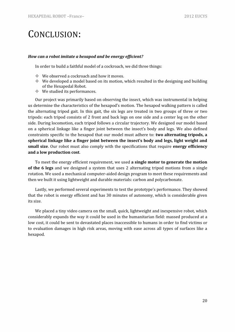
To obtain the best possible adhesion of the legs to the ground, we decided to test
several options. We calculated the coefficient of friction of each option and chose the most
efficient one; we attached some rubber under each leg.
These experiments are detailed in chapter III. B.
STEERING
To enable the robot to turn, we attached two linear servomotors to the rear. Each of the
servomotors pulls one of the front corners of the robot’s frame. The servomotors are connected
to the front corners via a thin carbon rod (See figure 16).
Figure 16: Top view of the Hexapedal Robot
When the servomotors are actuated, the frame is distorted. This distortion slightly
modifies the axis of rotation of the legs and enables the robot to turn.
Servomotors Carbon rods

HEXAPEDAL ROBOT –France– 2012 EUCYS
15
II. PERFORMANCES OF THE PROTOTYPE
A. GENERAL PRESENTATION
MATERIAL
The body of the robot is made of carbon fibre (0.3 mm thick) and the legs are made of
polycarbonate (0.5 mm thick). We chose these materials because they are both light-weight
and rigid. The carbon beams used to construct our robot are rigid when forces are directed along
the length of the beam. However, because they are very thin, they lack rigidity when subjected to
forces directed into their side.
All the parts of the body are assembled with cyanoacrylate glue or reinforced tape.
DIMENSIONS
Figure 17: Model generated with Solidworks
8

HEXAPEDAL ROBOT –France– 2012 EUCYS
16
COMPONENTS
To meet our constraints of light-weight and low power consumption, we equipped our
robot with as few components as possible:
One single DC gear motor which
imparts movement to the legs. It weighs 1.3
grams, is designed for 3V nominal operation,
giving 920 RPM (Rounds per Minute) and
contains a gear reduction of 25:1.
An integrated circuit which includes
two linear servomotors. These servomotors
are used to steer the robot. The integrated
circuit enables to control all the components
remotely.
A Li-Po (Lithium Polymer) battery,
which powers all the components. It weighs
2.7g, has a 3.7V voltage and 80 mAh capacity.
MASS OF THE ROBOT, WITH ALL ITS COMPONENTS
The small mass of our robot is a key feature which contributes to reducing its power
consumption. It is about the same as a cockroach’s mass, which varies from 10 to 20g.
CAMERA
We added a camera to the body of the robot. Thus, it can be sent into disaster areas to
search for victims and carry out surveillance missions.
To be used in humanitarian crises, our robot requires:
A video lens which captures the live images. It weighs 1 gram.
A transmitter which communicates the video signals from the robot to an
external receiver. The transmitter weighs 2.2 grams and works at a frequency of
5.8 GHz.
A 2 dB and 5.8 GHz antenna which is incorporated to the receiver.
Battery Gear motor
Servomotors
Integrated
citcuit
HEXAPEDAL ROBOT –France– 2012 EUCYS
17
B. PERFORMANCES OF THE ROBOT
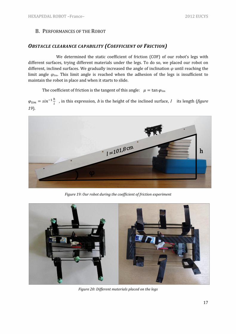
OBSTACLE CLEARANCE CAPABILITY (COEFFICIENT OF FRICTION)
We determined the static coefficient of friction (COF) of our robot’s legs with
different surfaces, trying different materials under the legs. To do so, we placed our robot on
different, inclined surfaces. We gradually increased the angle of inclination φ until reaching the
limit angle φlim. This limit angle is reached when the adhesion of the legs is insufficient to
maintain the robot in place and when it starts to slide.
The coefficient of friction is the tangent of this angle: lim
, in this expression, h is the height of the inclined surface, l its length (figure
19).
Figure 19: Our robot during the coefficient of friction experiment
Figure 20: Different materials placed on the legs
h
φ

HEXAPEDAL ROBOT –France– 2012 EUCYS
18
Here are our results:
Materials Plastic-coated wood
(smooth) Plastic (grainy) Concrete
Polycarbonate 0,29 0,44 -
Rubber 0,51 0,76 0,82
Our robot moves easily on various surfaces such as gravel and concrete, on inclined
planes (up to 25 degrees) and it can clear obstacles around a few centimetres height.
Figure 21: robot on sand and wooden floor
DROP-TEST PERFORMANCE
Our robot can withstand falls around one metre, and so can be used in rough terrain.
This is due to the lack of rigidity of the beams when forces are directed into their side. Thus, the
body is contorted when it reaches the ground, and part of the energy is absorbed, preventing the
robot from being damaged.
SPEED PERFORMANCE
To calculate our robot’s speed, we determined how much time it needed to cover one
metre, once the launching of the robot is finished:
Starting line Finishing line

HEXAPEDAL ROBOT –France– 2012 EUCYS
19
We obtained the following speeds:
Material Speed
Wooden floor, not inclined
Concrete, not inclined
Wooden plane, inclined of 19,0°
Our robot runs faster on wooden floors than on concrete because the roughness of the
concrete slows its progress.
ENERGY CONSUMPTION PERFORMANCE
The energy consumed by the robot during 5 minutes of use is:
To find the intensity released by the battery during the run, we divided its capacity
(80mAh) by our robot’s autonomy A, experimentally measured:
and
In conclusion, we obtained:
HEXAPEDAL ROBOT –France– 2012 EUCYS
20
CONCLUSION:
How can a robot imitate a hexapod and be energy efficient?
In order to build a faithful model of a cockroach, we did three things:
We observed a cockroach and how it moves. We developed a model based on its motion, which resulted in the designing and building
of the Hexapedal Robot. We studied its performances.
Our project was primarily based on observing the insect, which was instrumental in helping
us determine the characteristics of the hexapod’s motion. The hexapod walking pattern is called
the alternating tripod gait. In this gait, the six legs are treated in two groups of three or two
tripods: each tripod consists of 2 front and back legs on one side and a center leg on the other
side. During locomotion, each tripod follows a circular trajectory. We designed our model based
on a spherical linkage like a finger joint between the insect’s body and legs. We also defined
constraints specific to the hexapod that our model must adhere to: two alternating tripods, a
spherical linkage like a finger joint between the insect’s body and legs, light weight and
small size. Our robot must also comply with the specifications that require energy efficiency
and a low production cost.
To meet the energy efficient requirement, we used a single motor to generate the motion
of the 6 legs and we designed a system that uses 2 alternating tripod motions from a single
rotation. We used a mechanical computer-aided design program to meet these requirements and
then we built it using lightweight and durable materials: carbon and polycarbonate.
Lastly, we performed several experiments to test the prototype’s performance. They showed
that the robot is energy efficient and has 30 minutes of autonomy, which is considerable given
its size.
We placed a tiny video camera on the small, quick, lightweight and inexpensive robot, which
considerably expands the way it could be used in the humanitarian field: massed produced at a
low cost, it could be sent to devastated places inaccessible to humans in order to find victims or
to evaluation damages in high risk areas, moving with ease across all types of surfaces like a
hexapod.

HEXAPEDAL ROBOT –France– 2012 EUCYS
21
Sources:
1 Robot DASH + Wings – Biomimetic Millisystems Lab, Berkeley University.
P. Birkmeyer, K. Peterson and R. S. Fearing
SCM Process : Fast scale prototyping for folded millirobots
M. Hoover and R. S. Fearing
2 Models made using Solidworks
http://www.solidworks.fr/
3 Photos taken from a video of a cockroach running:
Video presenting the DASH robot - Biomimetic Millisystems Lab, Berkeley University.
http://robotics.eecs.berkeley.edu/~ronf/Biomimetics.html
Céline LAY, Ophélia BOLMIN and Fanny RISBOURG (From the left to the right)