Embed Size (px)
DESCRIPTION
Heating & Cooling Circuit. OEM Boiler & Burner Equipment Nov 2006. Mixing heating circuit. Y21. Mixing cooling circuit. Mixing cooling circuit with a heat pump. Y21. B9. Y1/Y2. B21. Q9. Q2. RG1. B1. E9. B81. E10. P. P. K1/E11. B83. B71. Y21. B91. Q8/E14. - PowerPoint PPT Presentation
Citation preview
Empfohlen wird auf dem Titel der Einsatz eines vollflächigen Hintergrundbildes (Format: 25,4 x 19,05 cm):• Bild auf Master platzieren (JPG, RGB, 144dpi)• Bild in den Hintergrund legen
Empfohlen wird auf dem Titel der Einsatz eines vollflächigen Hintergrundbildes (Format: 25,4 x 19,05 cm):• Bild auf Master platzieren (JPG, RGB, 144dpi)• Bild in den Hintergrund legen
Confidential / Copyright © Siemens Schweiz AG 2006
Heating & Cooling Circuit
OEM Boiler & Burner EquipmentNov 2006

Seite 2 Nov 2006 Building Technologies / HVAC ProductsMarkus Herger
RVS – Heating & Cooling Circuit
Mixing heating circuit
Seite 3 Nov 2006 Building Technologies / HVAC ProductsMarkus Herger
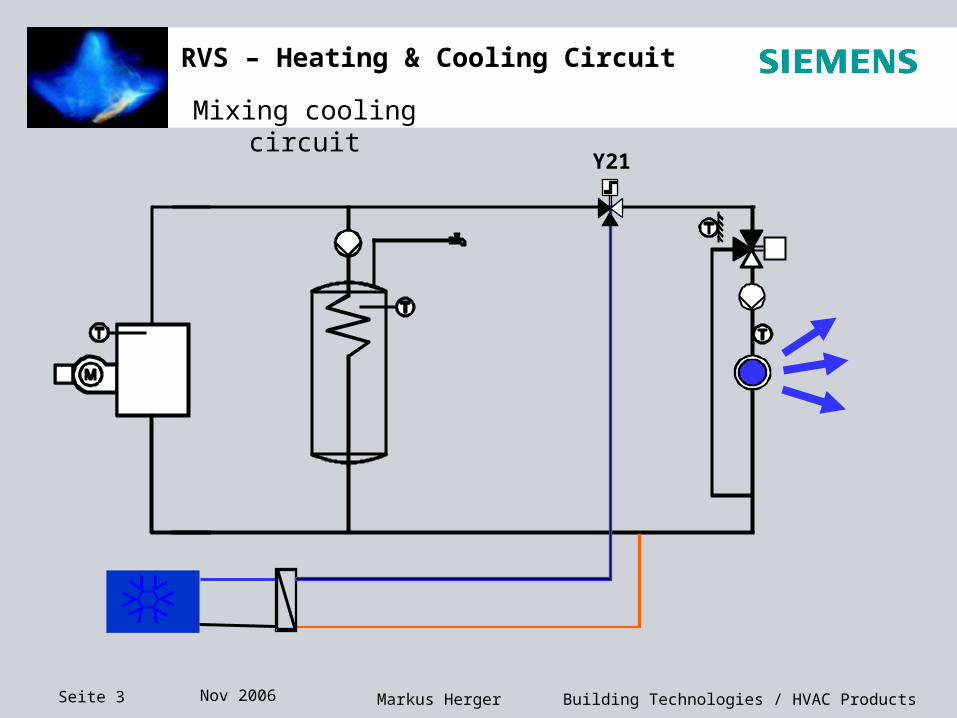
RVS – Heating & Cooling Circuit
Mixing cooling circuit
Y21
Seite 4 Nov 2006 Building Technologies / HVAC ProductsMarkus Herger
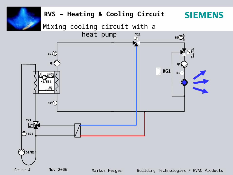
RVS – Heating & Cooling Circuit
Mixing cooling circuit with a heat pump
B21
K1/E11
B71
B83
B81E10P
E9P
Q8/E14
B91
Y21
Y21
Q2
B9
B1
Q9
RG1
Y1/Y
2
Seite 5 Nov 2006 Building Technologies / HVAC ProductsMarkus Herger
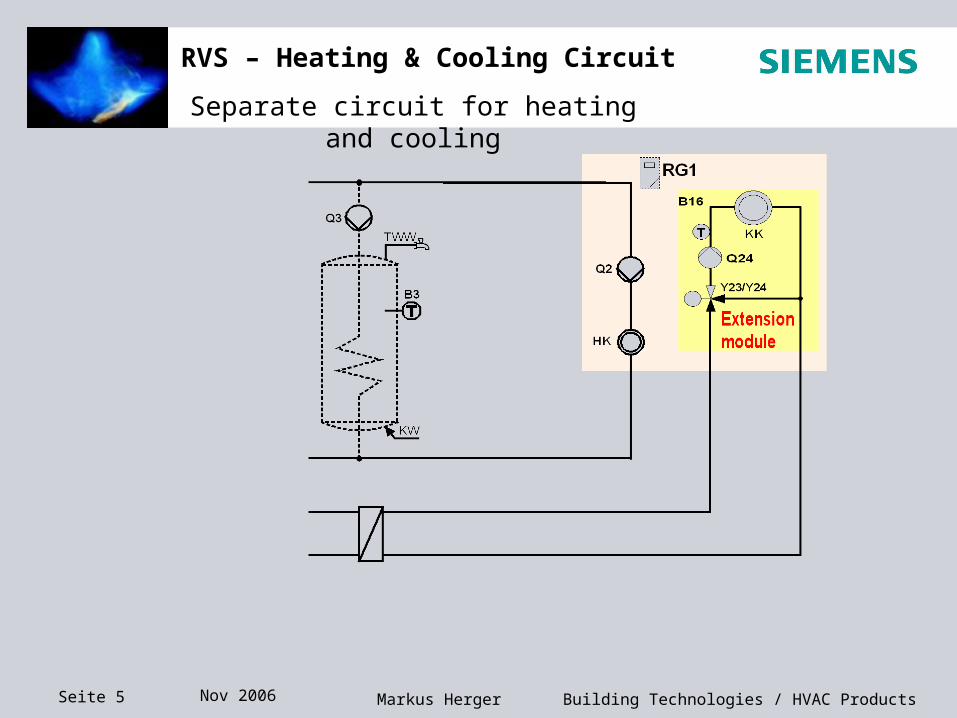
RVS – Heating & Cooling Circuit
Separate circuit for heating and cooling
Seite 6 Nov 2006 Building Technologies / HVAC ProductsMarkus Herger
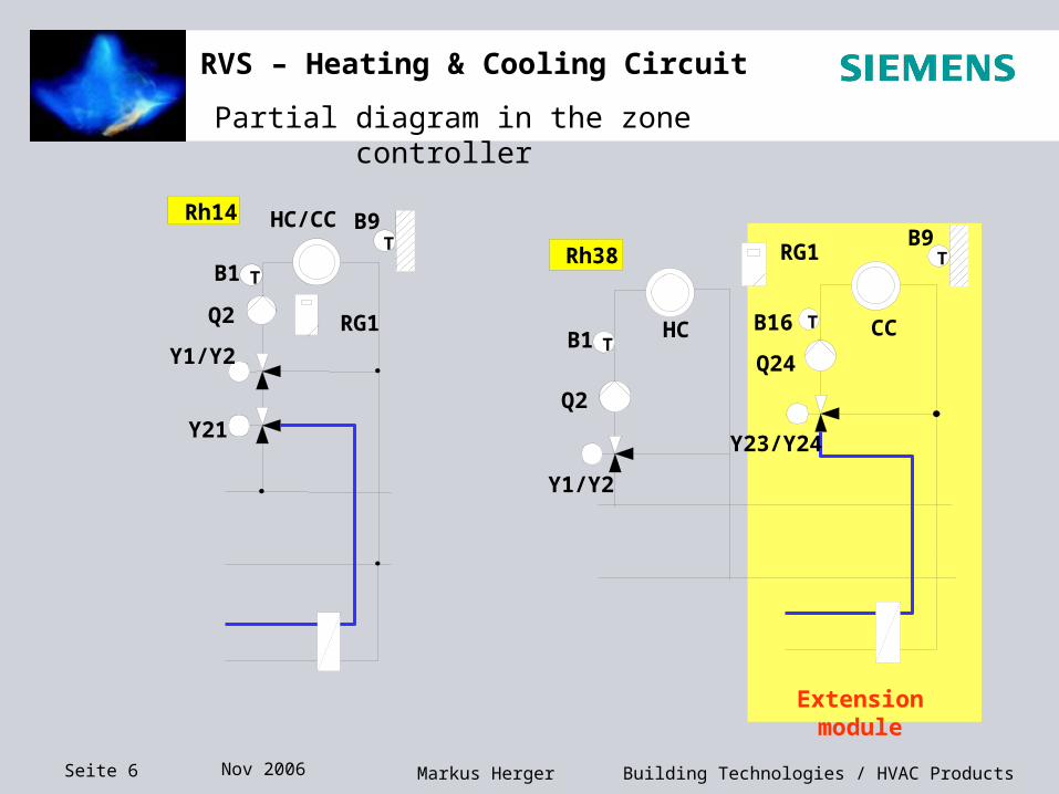
RVS – Heating & Cooling Circuit
Partial diagram in the zone controller
B1 T
Q2
Y1/Y2
Y21
Rh14 HC/CCT
B9
RG1B1 T
Q2
HC
Rh38 RG1 TB9
T CC
Y1/Y2
Q24
B16
Y23/Y24
Extension module
Seite 7 Nov 2006 Building Technologies / HVAC ProductsMarkus Herger
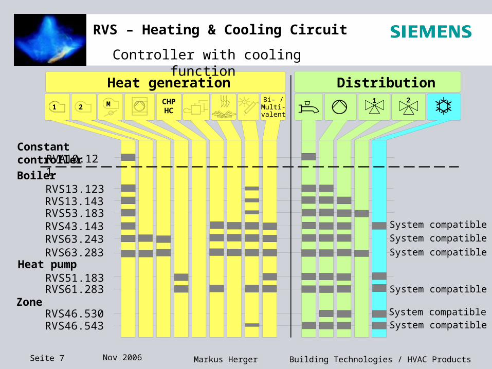
RVS – Heating & Cooling Circuit
Constant controller
Heat pump
CHP
HC
Heat generation Distribution
RVS13.123RVS13.143RVS53.183
RVS63.243RVS63.283
RVS61.283RVS51.183
RVA10.121
Boiler
RVS46.530
RVS43.143 System compatible
RVS46.543
Zone
1 21 2 M
Bi- /Multi-valent
System compatible
System compatible
System compatibleSystem compatible
System compatible
Controller with cooling function
Seite 8 Nov 2006 Building Technologies / HVAC ProductsMarkus Herger
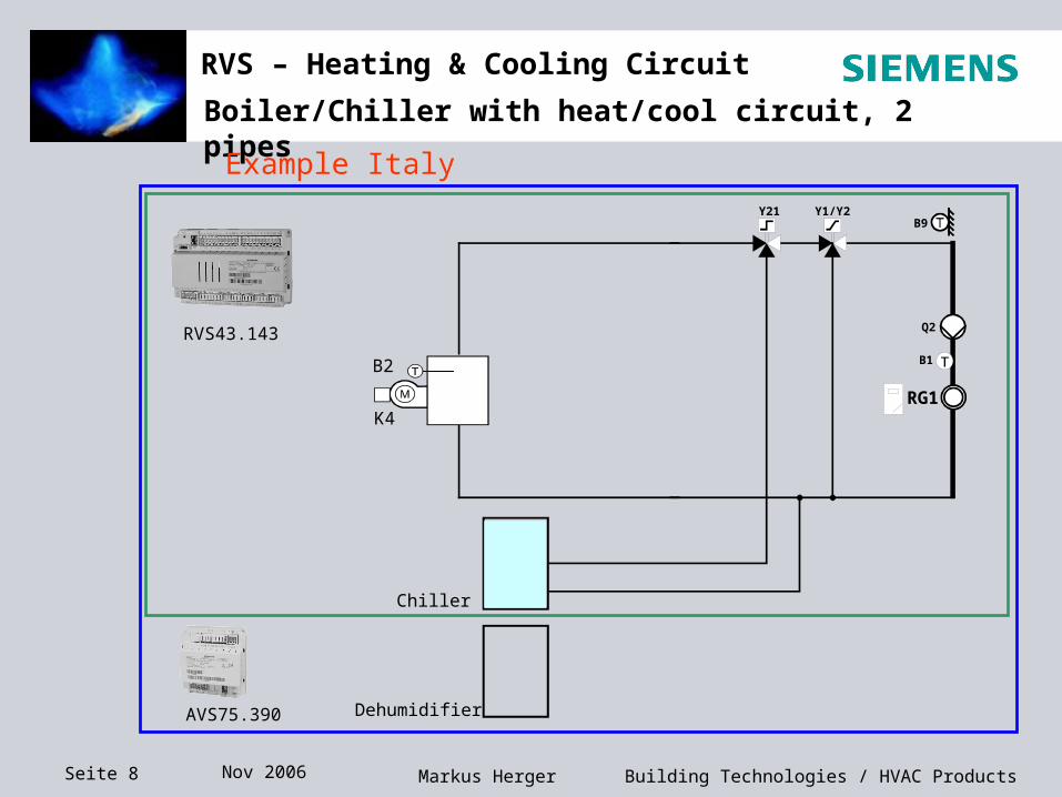
RVS – Heating & Cooling Circuit
Boiler/Chiller with heat/cool circuit, 2 pipes
Y21 Y1/Y2
Q2
B9
B1
RG1K4
B2
Chiller
Dehumidifier
RVS43.143
AVS75.390
Example Italy
Seite 9 Nov 2006 Building Technologies / HVAC ProductsMarkus Herger
RVS – Heating & Cooling Circuit
RESET
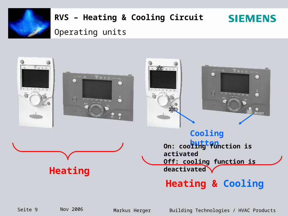
Operating units
Heating
Cooling buttonOn: cooling function is
activatedOff: cooling function is deactivated
Heating & Cooling
Seite 10 Nov 2006 Building Technologies / HVAC ProductsMarkus Herger
RVS – Heating & Cooling Circuit
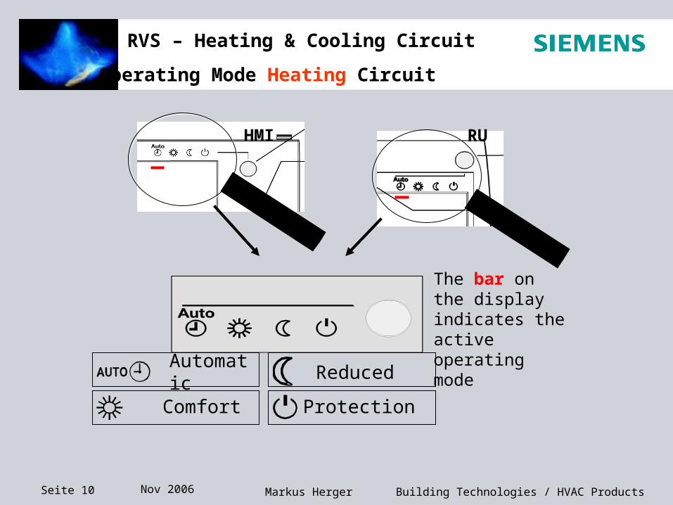
Automatic
Comfort
Reduced
Protection
HMI RU
The bar on the display indicates the active operating mode
Operating Mode Heating Circuit
Seite 11 Nov 2006 Building Technologies / HVAC ProductsMarkus Herger
RVS – Heating & Cooling Circuit
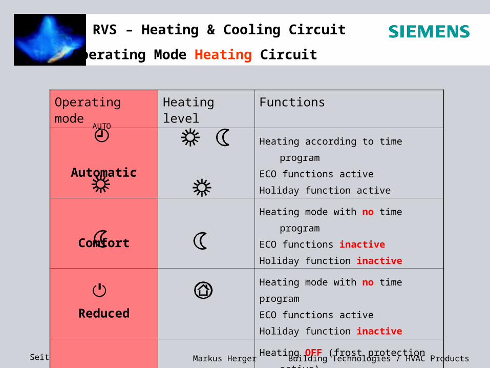
Operating Mode Heating Circuit
Operating mode Heating level Functions
Automatic
Heating according to time program
ECO functions active
Holiday function active
Comfort
Heating mode with no time program
ECO functions inactive
Holiday function inactive
Reduced
Heating mode with no time program
ECO functions active
Holiday function inactive
Protection
Heating OFF (frost protection active)
ECO functions active
Holiday function inactive
AUTO
Seite 12 Nov 2006 Building Technologies / HVAC ProductsMarkus Herger
RVS – Heating & Cooling Circuit
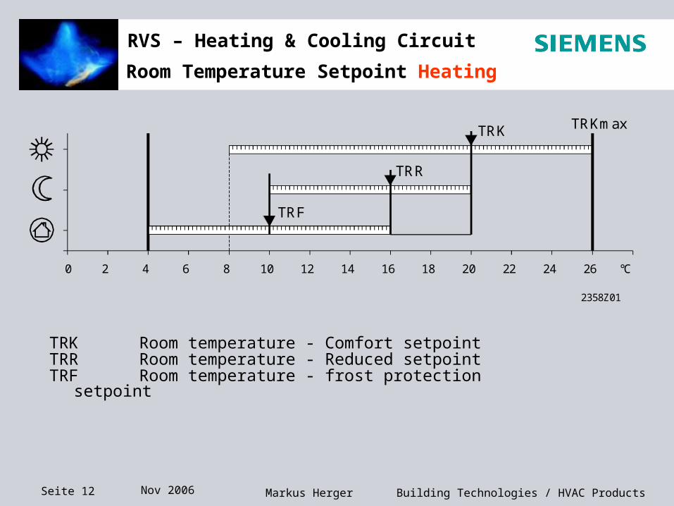
TRK Room temperature - Comfort setpoint TRR Room temperature - Reduced setpoint TRF Room temperature - frost protection
setpoint
0 2 4 6 8 10 12 14 16 18 20 22 24 26 °C
2358Z01
TRK
TRR
TRF
TRKmax
Room Temperature Setpoint Heating
Seite 13 Nov 2006 Building Technologies / HVAC ProductsMarkus Herger
RVS – Heating & Cooling Circuit
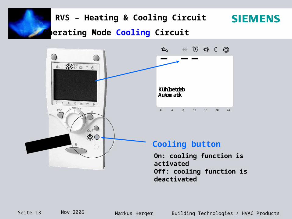
Operating Mode Cooling Circuit
Cooling buttonOn: cooling function is activatedOff: cooling function is deactivated
Gerät löschen? Ja
0 4 8 12 16 20 24
AUTO
KühlbetriebAutomatik
Seite 14 Nov 2006 Building Technologies / HVAC ProductsMarkus Herger
RVS – Heating & Cooling Circuit
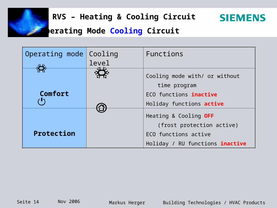
Operating Mode Cooling Circuit
Operating mode Cooling level Functions
Comfort
Cooling mode with/ or without time program
ECO functions inactive
Holiday functions active
Protection
Heating & Cooling OFF
(frost protection active)
ECO functions active
Holiday / RU functions inactive
Seite 15 Nov 2006 Building Technologies / HVAC ProductsMarkus Herger
RVS – Heating & Cooling Circuit
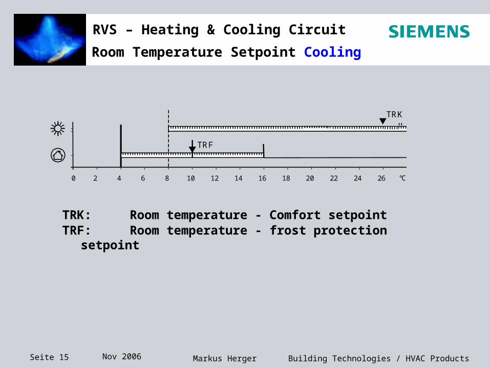
TRK: Room temperature - Comfort setpoint TRF: Room temperature - frost protection setpoint
0 2 4 6 8 10 12 14 16 18 20 22 24 26 °C
2358Z01
TRK
TRF
Room Temperature Setpoint Cooling
Seite 16 Nov 2006 Building Technologies / HVAC ProductsMarkus Herger
RVS – Heating & Cooling Circuit
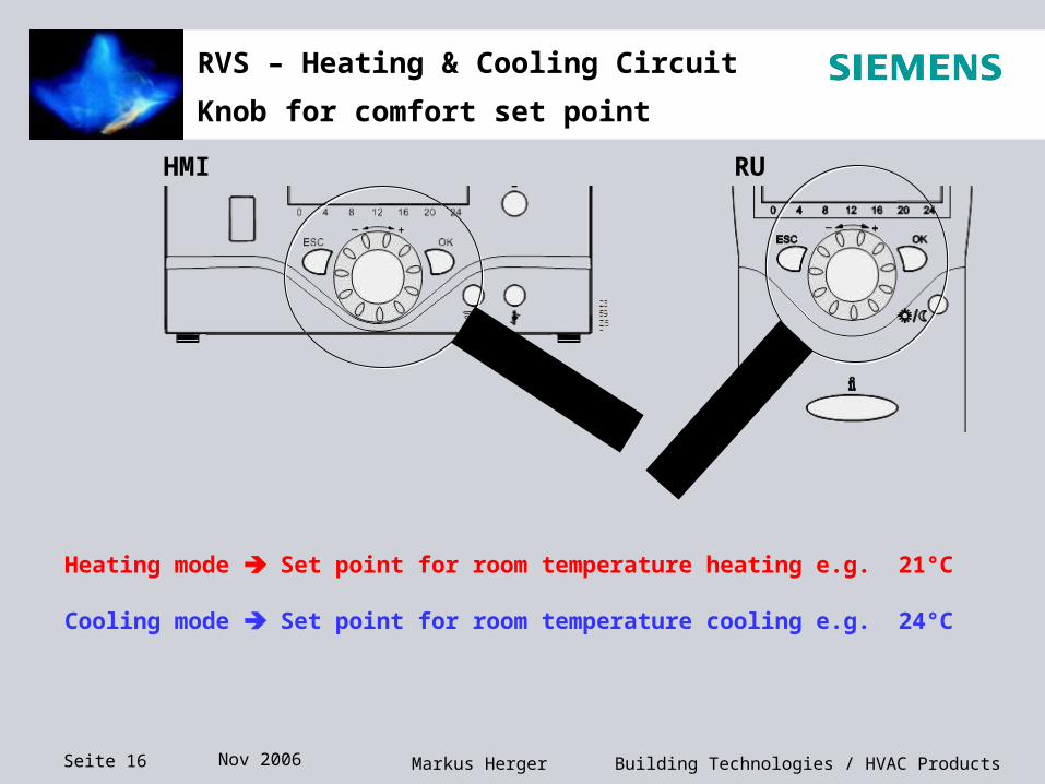
Knob for comfort set point
HMI RU
Heating mode Set point for room temperature heating e.g. 21°C
Cooling mode Set point for room temperature cooling e.g. 24°C
Seite 17 Nov 2006 Building Technologies / HVAC ProductsMarkus Herger
RVS – Heating & Cooling Circuit
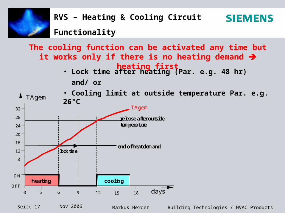
Functionality
ON
24
TAgem
TAgem
OFFdays
20
28
32
60
12
16
8
coolingheating
lock timeend of heat demand
release after outsidetemperature
12 153 9 18
• Lock time after heating (Par. e.g. 48 hr)
and/ or
• Cooling limit at outside temperature Par. e.g. 26°C
The cooling function can be activated any time but it works only if there is no heating demand heating first
Seite 18 Nov 2006 Building Technologies / HVAC ProductsMarkus Herger
RVS – Heating & Cooling Circuit
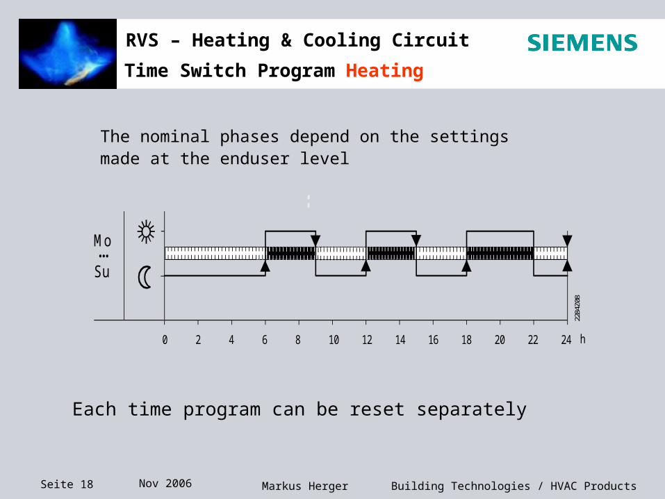
Time Switch Program Heating
The nominal phases depend on the settingsmade at the enduser level
0 2 4 6 8 10 12 14 16 18 20 22 24 h
Mo...Su
2284
Z08
Each time program can be reset separately
Seite 19 Nov 2006 Building Technologies / HVAC ProductsMarkus Herger
RVS – Heating & Cooling Circuit
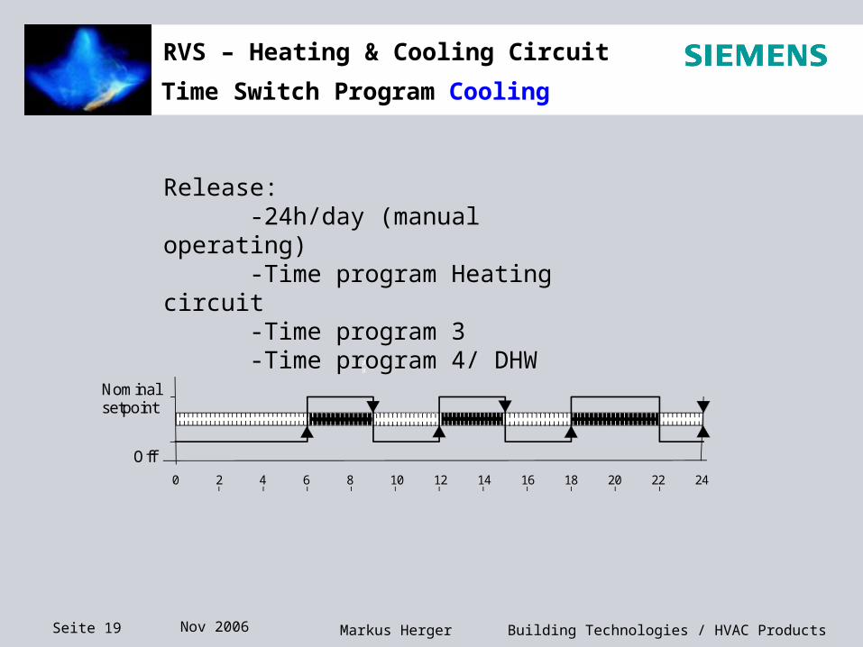
Release:-24h/day (manual operating)-Time program Heating circuit-Time program 3-Time program 4/ DHW
0 2 4 6 8 10 12 14 16 18 20 22 24
h
Nominalsetpoint
Off
Time Switch Program Cooling
Seite 20 Nov 2006 Building Technologies / HVAC ProductsMarkus Herger
RVS – Heating & Cooling Circuit
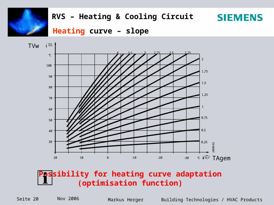
Heating curve – slope
20 10 0 -10 -20 -30
90
80
70
60
50
40
30
°C
°C
4 3,5 3 2,75 2,5 2,25
2
1,75
1,5
1,25
1
0,75
0,5
0,25
100
200
0D02
Possibility for heating curve adaptation (optimisation function)
TVw
TAgem
Seite 21 Nov 2006 Building Technologies / HVAC ProductsMarkus Herger
RVS – Heating & Cooling Circuit
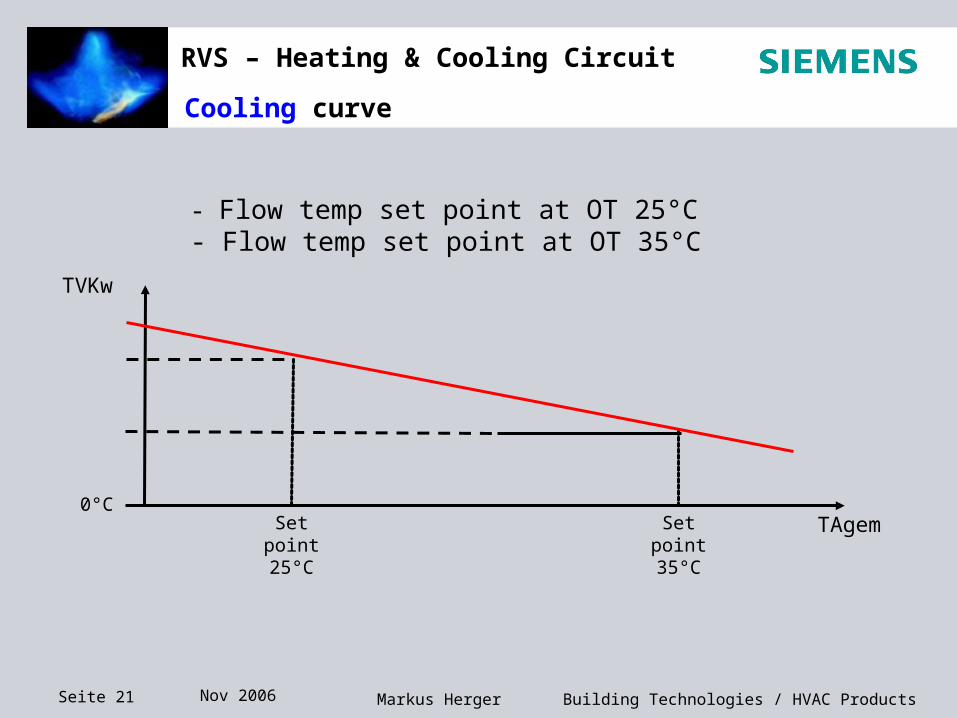
- Flow temp set point at OT 25°C - Flow temp set point at OT 35°C
TAgemSet point25°C
0°C
TVKw
Set point35°C
Cooling curve
Seite 22 Nov 2006 Building Technologies / HVAC ProductsMarkus Herger
RVS – Heating & Cooling Circuit
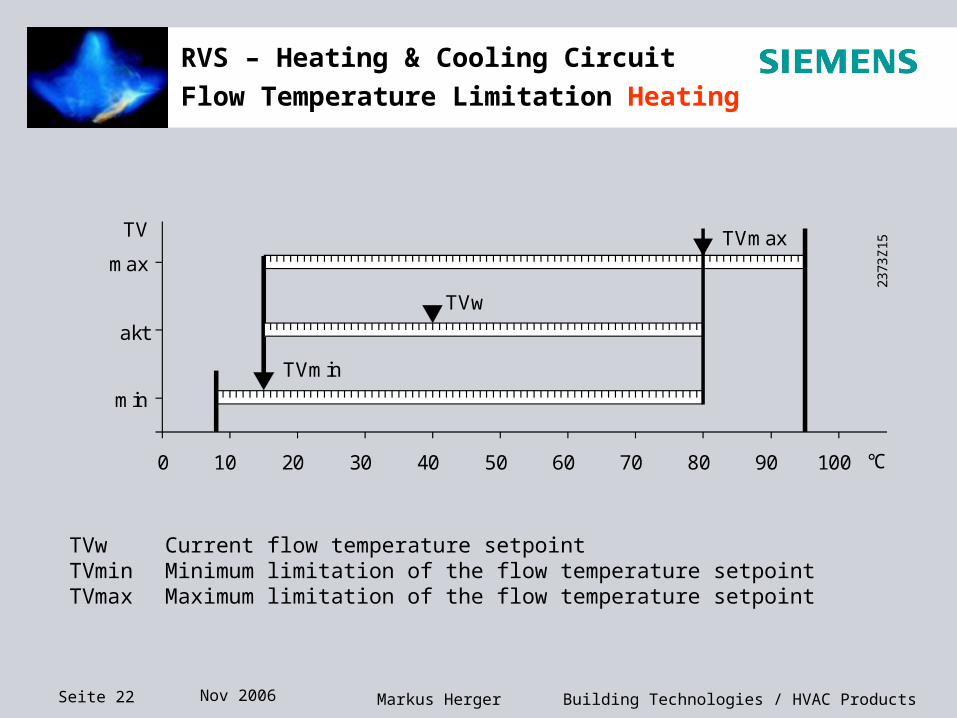
Flow Temperature Limitation Heating
0 10 20 30 40 50 60 70 80 90 100
TV
max
min
akt
°C
2373
Z15
TVw
TVmin
TVmax
TVw Current flow temperature setpointTVmin Minimum limitation of the flow temperature setpointTVmax Maximum limitation of the flow temperature setpoint
Seite 23 Nov 2006 Building Technologies / HVAC ProductsMarkus Herger
RVS – Heating & Cooling Circuit
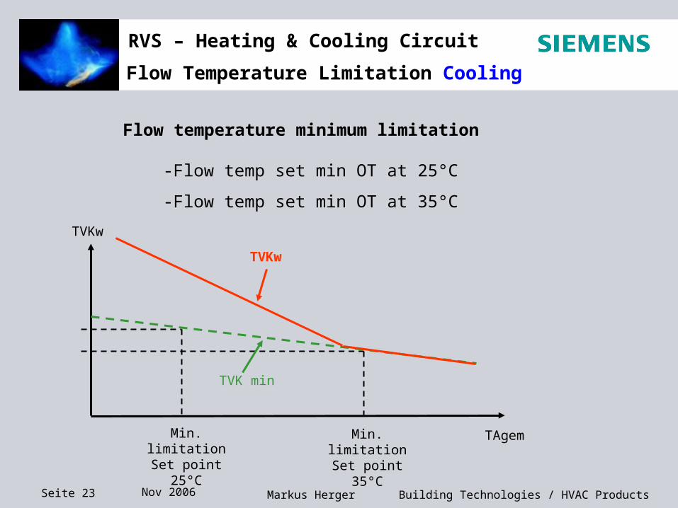
Flow temperature minimum limitation
-Flow temp set min OT at 25°C
-Flow temp set min OT at 35°C
TAgem
TVKw
TVK min
TVKw
Min. limitationSet point 25°C
Min. limitationSet point 35°C
Flow Temperature Limitation Cooling
Seite 24 Nov 2006 Building Technologies / HVAC ProductsMarkus Herger
RVS – Heating & Cooling Circuit
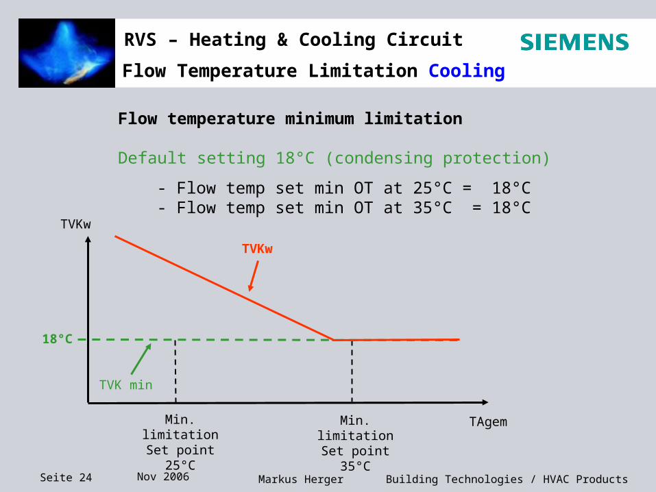
Flow temperature minimum limitation
Default setting 18°C (condensing protection)
- Flow temp set min OT at 25°C = 18°C- Flow temp set min OT at 35°C = 18°C
TAgem
TVKw
TVK min
TVKw
Min. limitationSet point 25°C
Min. limitationSet point 35°C
18°C
Flow Temperature Limitation Cooling
Seite 25 Nov 2006 Building Technologies / HVAC ProductsMarkus Herger
RVS – Heating & Cooling Circuit
Room Functions for Heating and Cooling
OFF
ONP
°C
TRxTRw+SDR
TRw
t
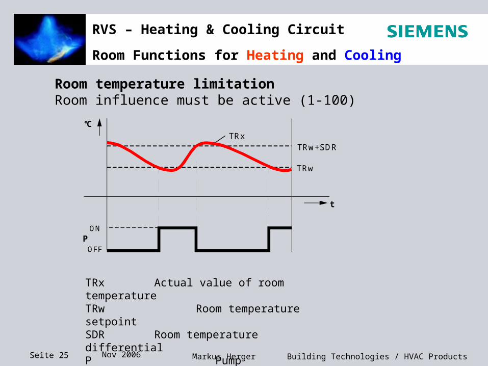
TRx Actual value of room temperatureTRw Room temperature setpointSDR Room temperature differentialP Pump
Room temperature limitation Room influence must be active (1-100)
Seite 26 Nov 2006 Building Technologies / HVAC ProductsMarkus Herger
RVS – Heating & Cooling Circuit
Room Functions only Heating
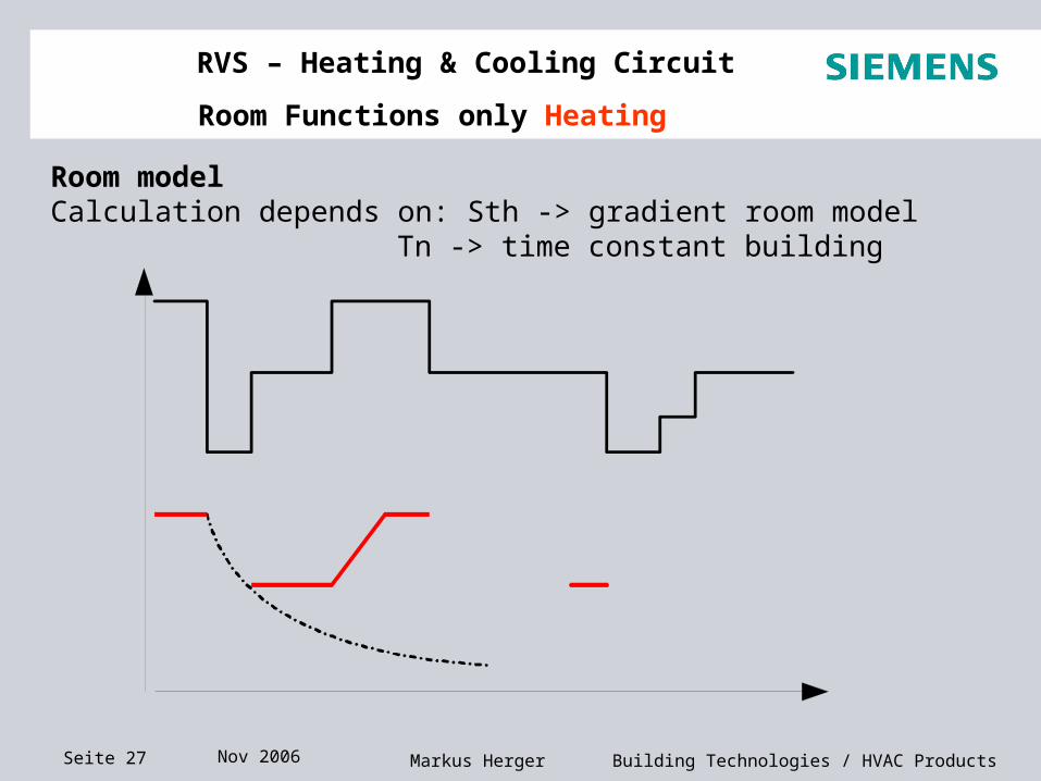
Room model
If there is no room sensor connected or room influence is deactivated, the control calculates a virtual room temperature which is used for the following functions:
- Boost heating- Quick setback- Optimum start control- Optimum stop control
Seite 27 Nov 2006 Building Technologies / HVAC ProductsMarkus Herger
RVS – Heating & Cooling Circuit
Room Functions only Heating
Room modelCalculation depends on: Sth -> gradient room model
Tn -> time constant building
Comf
Red
Frost
TAgem
Comf
Red
Frost
TAgem Tn
Tn
Tn
TRw
Sth
Sth
Seite 28 Nov 2006 Building Technologies / HVAC ProductsMarkus Herger
RVS – Heating & Cooling Circuit
Room Functions only Heating
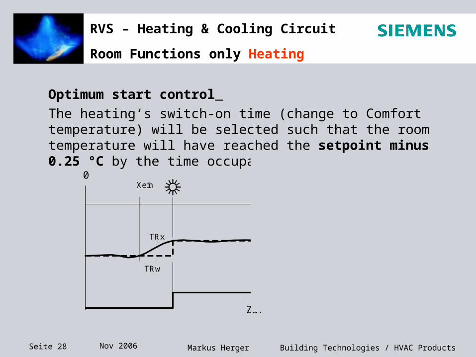
Optimum start control
The heating‘s switch-on time (change to Comfort temperature) will be selected such that the room temperature will have reached the setpoint minus 0.25 °C by the time occupancy starts.
0 24
235
8Z02
Xein Xaus
TRx
TRw
ZSP
1/4 °C
Seite 29 Nov 2006 Building Technologies / HVAC ProductsMarkus Herger
RVS – Heating & Cooling Circuit
Room Functions only Heating
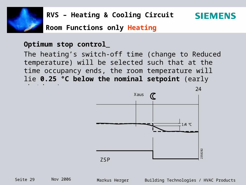
Optimum stop control
The heating’s switch-off time (change to Reduced temperature) will be selected such that at the time occupancy ends, the room temperature will lie 0.25 °C below the nominal setpoint (early shutdown).
0 24
235
8Z02
Xein Xaus
TRx
TRw
ZSP
1/4 °C
Seite 30 Nov 2006 Building Technologies / HVAC ProductsMarkus Herger
RVS – Heating & Cooling Circuit
ECO Functions only heating
Temp
TimeOffOn
Actual outside temp.
Composite outside temp.
24-hourheating limit
1°K
Diff.
Room setpoint
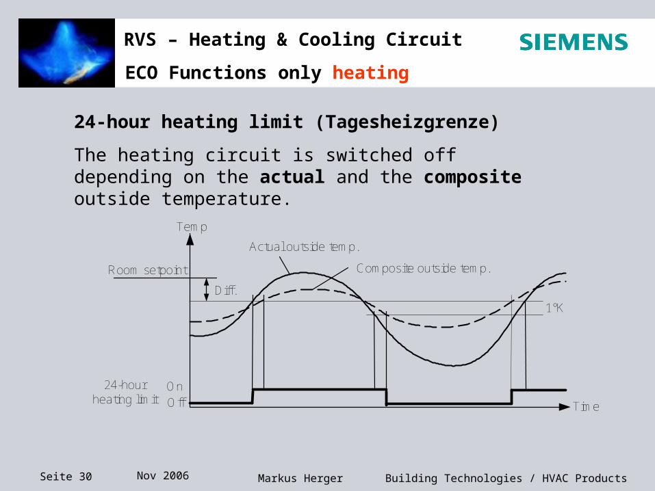
24-hour heating limit (Tagesheizgrenze)
The heating circuit is switched off depending on the actual and the composite outside temperature.
Seite 31 Nov 2006 Building Technologies / HVAC ProductsMarkus Herger
RVS – Heating & Cooling Circuit
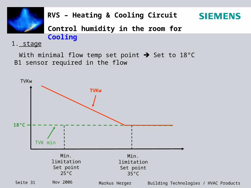
Control humidity in the room for Cooling
1. stage
With minimal flow temp set point Set to 18°C B1 sensor required in the flow
TVKw
TVK min
TVKw
Min. limitationSet point 25°C
Min. limitationSet point 35°C
18°C
Seite 32 Nov 2006 Building Technologies / HVAC ProductsMarkus Herger
RVS – Heating & Cooling Circuit
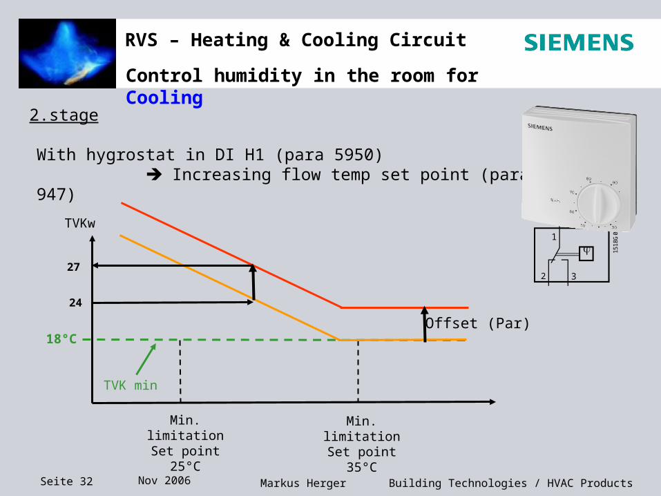
Control humidity in the room for Cooling
2.stage
With hygrostat in DI H1 (para 5950) Increasing flow temp set point (para 947)
TVKw
TVK min
Min. limitationSet point 25°C
Min. limitationSet point 35°C
18°COffset (Par)
24
27
1
2 3
1518
G01

Seite 33 Nov 2006 Building Technologies / HVAC ProductsMarkus Herger
RVS – Heating & Cooling Circuit
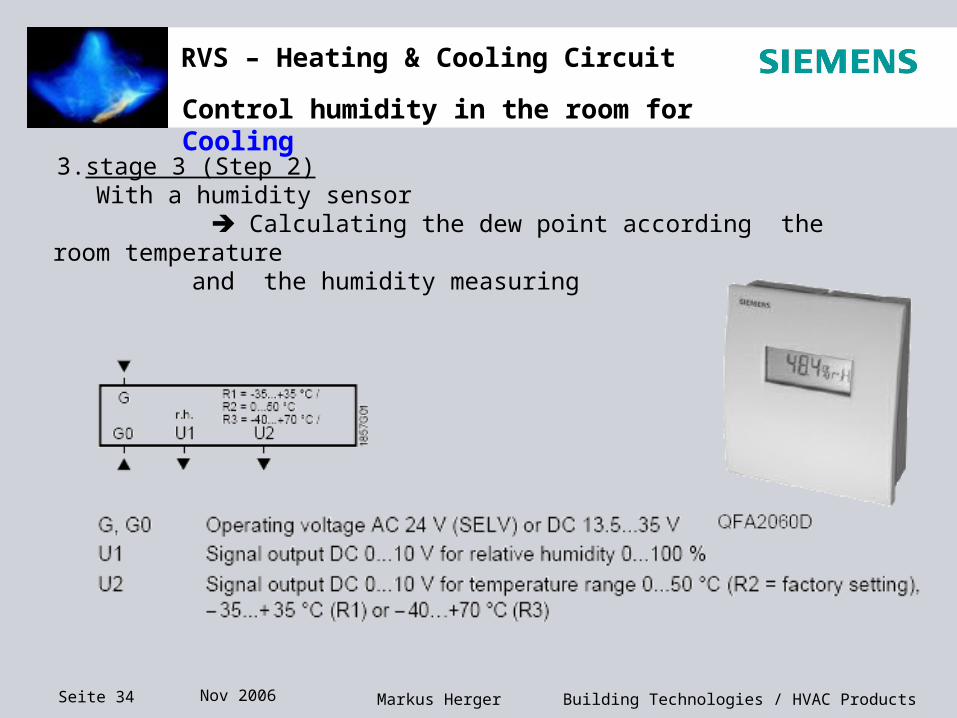
Control humidity in the room for Cooling
2.stage
or with dew point monitor Switched off the cooling function for a set time (para 946)
3.stage 3 (Step 2) With a humidity sensor Calculating the dew point according the room temperature
and the humidity measuring
1
2 3
1518
G01
stop
Seite 34 Nov 2006 Building Technologies / HVAC ProductsMarkus Herger
RVS – Heating & Cooling Circuit
Control humidity in the room for Cooling
3.stage 3 (Step 2) With a humidity sensor Calculating the dew point according the room temperature
and the humidity measuring