Embed Size (px)
Citation preview
Purdue UniversityPurdue e-Pubs
CTRC Research Publications Cooling Technologies Research Center
2010
Heat Transfer in Trapezoidal Microchannels ofVarious Aspect RatiosJohn P. McHalePurdue University - Main Campus
S V. GarimellaPurdue University, [email protected]
Follow this and additional works at: http://docs.lib.purdue.edu/coolingpubs
This document has been made available through Purdue e-Pubs, a service of the Purdue University Libraries. Please contact [email protected] foradditional information.
McHale, John P. and Garimella, S V., "Heat Transfer in Trapezoidal Microchannels of Various Aspect Ratios" (2010). CTRC ResearchPublications. Paper 121.http://dx.doi.org/10.1016/j.ijheatmasstransfer.2009.09.020
1
Heat Transfer in Trapezoidal Microchannels of Various Aspect Ratios1
John P. McHale and Suresh V. Garimella2
Cooling Technologies Research Center
School of Mechanical Engineering and Birck Nanotechnology Center
Purdue University, West Lafayette, Indiana 47907-2088 USA
ABSTRACT
Heat transfer in the thermal entrance region of trapezoidal microchannels is investigated
for hydrodynamically fully developed, single-phase, laminar flow with no-slip conditions.
Three-dimensional numerical simulations were performed using a finite-volume approach for
trapezoidal channels with a wide range of aspect ratios. The sidewall angles of 54.7° and 45°
are chosen to correspond to etch-resistant planes in the crystal structure of silicon. Local and
average Nusselt numbers are reported as a function of dimensionless length and aspect ratio.
The effect of Prandtl number upon the thermal entrance condition is explored. The fully
developed friction factors are computed and correlated as a function of channel aspect ratio.
Correlations are also developed for the local and average Nusselt numbers in the thermal
entrance region as a function of a dimensionless axial length variable.
Keywords: Microchannel, thermally developing, liquid cooling, heat sink, trapezoid
1 Submitted for publication in International Journal of Heat and Mass Transfer, February 2009, and in
revised form, August 2009
2 Author to whom correspondence should be addressed: 765-494-5621, [email protected]

2
NOMENCLATURE
A surface area
a half-width of small base of trapezoid
b channel half-height
Cn nth constant in parallel-plates solution, Equation (1)
cp fluid constant-pressure specific heat
Dh channel hydraulic diameter
H specific total enthalpy
h convective heat transfer coefficient
k fluid thermal conductivity
L channel length
m mass flow rate
Nu Nusselt Number, h∙Dh/k
p pressure
Pr Prandtl number, /
q heat flux
q volumetric heat generation
hDRe Reynolds number based on channel hydraulic diameter
T temperature
u axial velocity
x x-coordinate
Yn nth eigenfunction in parallel-plates solution, Equation (1)
y y-coordinate
y* dimensionless transverse coordinate
z z-coordinate (axial coordinate)
z* dimensionless axial coordinate
Greek
channel aspect ratio, 2a / 2b
n nth eigenvalue in parallel-plates solution, Equation (1)

3
dimensionless axial coordinate normalized by thermal development length, z*/L
*th
fluid dynamic viscosity
fluid kinematic viscosity
fluid density
channel sidewall angle
Subscripts
avg average
f fluid
fd fully developed
m mean
n summation index
w wall
z local
INTRODUCTION
Common fabrication techniques enable the production of many different microchannel
cross-sectional shapes, including rectangular, circular, triangular, and trapezoidal. The use of an
anisotropic etchant such as potassium hydroxide (KOH) or tetramethylammonium hydroxide
(TMAH) produces a geometry in a silicon substrate which is either trapezoidal or triangular,
depending upon the depth to which etching is allowed to proceed. These etchants have a high
(100~250:1) selectivity to the (100) and (110) crystal planes relative to the (111) crystal plane,
producing a channel sidewall angle of approximately 54.7° or 45°, depending upon the
orientation of the patterned geometry [1,2]. Anisotropic etching processes are relatively fast and
inexpensive; thus, production of microchannels may be readily integrated into the chip
fabrication process stream if desired. Thus trapezoidal microchannels hold promise for
integrated heat sinking and lab-on-a-chip applications, the design of which is dependent upon the
fluid flow and heat transfer behaviors of these channels. The unique conditions of liquid flow
and heat transfer in uniformly heated trapezoidal microchannels has not been considered in detail
in the literature. The present work reports thermally developing flow solutions over the entire

4
range of possible aspect ratios and provides correlations for predicting friction factors and local
and average Nusselt numbers in ducts under the given conditions.
Much effort has been directed in recent years to characterize the heat transfer behavior of
fluid flow in ducts of various shapes and sizes. Studies that are most relevant to the current work
are compared in Table 1. Friction factor and Nusselt number values for fully developed,
thermally developing, hydrodynamically developing, and simultaneously developing conditions
from the literature have been catalogued by Shah and London [3] and Kakac, et al. [4]. These
results have been applied to predict the behavior of microchannels beginning with Tuckerman
and Pease [5]. It has been shown by Judy, et al. [6], Liu and Garimella [7], and Lee, et al. [8]
that microchannel flow and heat transfer exhibit continuum behavior in single-phase flows for
channel dimensions of interest in high-flux cooling applications. Therefore, results from
macroscale channels can be directly applied to such microchannels. However, flow in
microchannels may not generally be assumed to be fully developed. Shah [9] summarized his
studies of compact heat exchangers and noted the effects of flow development on the thermal
performance. Phillips [10] extended these conclusions to microchannel heat sinks and
recommended that flow be considered thermally developing but hydrodynamically fully
developed. Lee, et al. [8] showed by comparing experimental and numerical data from
rectangular microchannels that the assumption of thermally developing flow (TDF) predicts
average Nusselt numbers within 5% of the experimental values over the entire range of laminar
Reynolds numbers. A departure was observed beginning at Reynolds numbers between 1500
and 2000, and was attributed to the beginning of transition to turbulent flow. Numerical results
were also compared to show that the H1 boundary condition described in [3] effectively
represents the 3-D conjugate heat transfer occurring in a microchannel heat sink.
Limited heat transfer and friction factor results are available for ducts with a sidewall
angle of 54.7°. Harley, et al. [11] experimentally investigated the frictional pressure drop for
flow through channels etched in <100>- and <110>-oriented silicon for a variety of fluids. For
small trapezoidal channels, the experimentally observed friction factors were significantly higher
than those predicted for fully developed flow. Flockhart and Dhariwal [12] experimentally and
numerically determined fully developed friction factors in trapezoidal channels with 54.7°
sidewall angles and found good agreement between the two; for channels of shorter length,
however, there was less agreement, which could be attributed to flow development effects not

5
having been considered. Farhanieh and Sunden [13] examined heat transfer in the hydrodynamic
entrance region of isosceles trapezoidal ducts using a finite volume method, but their results
were limited to developing-flow friction factors and fully developed Nusselt numbers for
sidewall angles of 30°, 45°, 60°, and 90°. Using a successive grid length ratio in the streamwise
direction and uniform spacing in the other two directions, they showed that satisfactory
agreement could be achieved with theoretical results from Shah and London [3]. Rujano and
Rahman [14] obtained results from a numerical analysis for a sidewall angle of 54.7°; their
results were compared to experiments with relatively good agreement, but the numerical values
for Nusselt number were consistently lower than the experimental ones. The results did not
accurately reproduce the expected local Nusselt number at z* = 0 and were not generalized for a
range of parameters. Heat transfer and pressure drop in trapezoidal microchannels with a 54.7°
sidewall angle and with three heated walls were experimentally investigated by Qu, et al.
[15,16], who obtained good agreement with theory when an adjusted coolant viscosity was
included to account for surface roughness of the channels. Rahman and Shevade [17]
experimentally and numerically studied flow in trapezoidal microchannels with heating on all
four walls, and concluded that the effects of thermal boundary layer development were
significant. Wu and Cheng experimentally investigated both friction factors [18] and heat
transfer [19] in trapezoidal microchannels, while considering the effects of other parameters such
as surface conditions. They found that channel geometry had a much more significant effect on
the Nusselt number than did roughness or hydrophilicity of the wall surfaces. Correlations fit to
their data did not explicitly include the effects of dimensionless length.
Other researchers have used numerical methods to study mainly fully developed flow in
equilateral and isosceles triangular channels [20,21]. Sadasivam, et al. [22] provided
correlations for Nusselt numbers and friction factors under fully developed conditions in
trapezoidal and hexagonal ducts with sidewalls at 30°, 45°, 60°, and 75° based on finite-
difference solutions. Bahrami, et al. used the similarity between the governing equations of
beam torsion and fluid flow in ducts to develop an approximate method for predicting pressure
drop in ducts of arbitrary cross section including a trapezoidal shape [23] and randomly rough
microtubes [24]. They then extended the work to evaluate the heat transfer in rough
microchannels [25] and found little enhancement due to reasonable values of surface roughness.
Steinke and Kandlikar [26] compared many of the results in the literature for single-phase

6
friction factors in different microchannel shapes. Rokni and Sunden [27] investigated fully
developed friction factors and Nusselt numbers under turbulent conditions in trapezoidal ducts
with a small set of sidewall angles and aspect ratios.
Thermally developing flow in microchannels of different shapes has been investigated by
several researchers. Wei and Joshi [28] combined two of Shah’s correlations [29,30] in order to
predict the thermally developing Nusselt number in rectangular channels. More recently, Lee
and Garimella [31] conducted a detailed study of heat transfer in thermally developing flow
through rectangular microchannels of various aspect ratios, and developed generalized
correlations for local and average Nusselt numbers. Talukdar and Shah [32] studied mixed
convection in triangular ducts with simultaneously developing conditions and found that the
local Nusselt number fluctuated along the channel length due to buoyancy-driven circulation.
Renksizbulut and Niazmand [33] numerically studied the entrance region of trapezoidal channels
with sidewalls at 30°, 45°, 60°, and 90°, and aspect ratios of 0.5, 1.0, and 2.0, recommending
correlations for fRe, Nufd, and entrance length. Niazmand, et al. [34] extended the analysis to
include slip flow over a slightly wider range of channel aspect ratios, modifying the previous
correlation to include the effects of velocity slip at the wall. The velocity and temperature fields
were considered to be simultaneously developing, with a fluid having Pr = 1, and the thermal
boundary condition was the uniform temperature, or Ⓣ, condition. Wang, et al. [35] compared
experimental and numerical results for simultaneously developing water flow in a trapezoidal
microchannel with 54.7° sidewalls and a single uniformly heated wall. The predictions were
found to agree well with the experiments confirming the applicability of the continuum
assumption for the Navier-Stokes equations; a thermal development length was also identified.
The present study follows on the recommendations of Lee, et al. [8] for liquid flow in
microchannels and applies the H1 boundary the trapezoidal channel with sidewalls at 54.7° or
45°. The purpose of this study is to explore the effect of aspect ratio and axial length upon the
local and average heat transfer coefficients in the trapezoidal duct, and to provide generalized
correlations for the corresponding Nusselt numbers and friction factors. The results of this study
are helpful for the design and optimization of trapezoidal microchannel heat sinks.

7
MATHEMATICAL FORMULATION
Exact solutions are available for thermally developing flow in parallel plates and circular
pipes [29,36-43]. The solution to the parallel-plates problem provides a foundation for
understanding the general characteristics of thermally developing flow. Sparrow, et al. [43]
derived the solution for a variety of boundary conditions, including prescribed temperature,
prescribed heat flux, and energy generation within the fluid. Shah and London [3] simplified the
results of [43] for constant fluid properties, for no internal energy generation, and with axial
conduction neglected, to the following form:
2 *32 3
1
1 17 1(1)
140 4n z
n n
nz
C Y eNu
, (1)
where n, Yn, and Cn are eigenvalues, eigenfunctions, and constants, respectively, related to the
Sturm-Liouville system [43] with Neumann boundary conditions
2
2 * 2
* 21 ( ) 0
( )
nn n
d Yy Y
dy ,
0,1
0n
y
dY
dy
, (2)
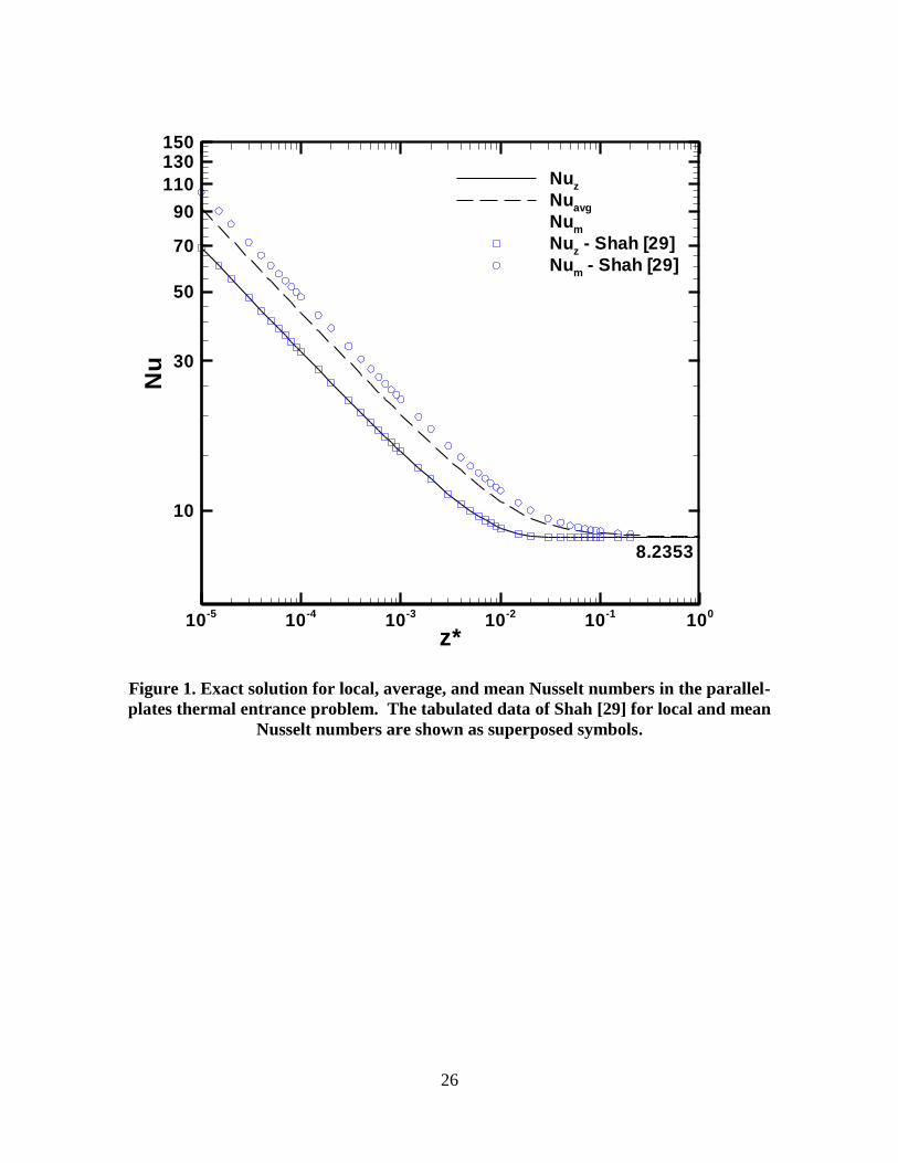
in which y* is the dimensionless transverse coordinate. The series in Equation (1) is evaluated
numerically using the first 500 terms in the series solution and plotted against nondimensional
length in Figure 1. In the figure, the three curves shown are the local Nusselt number Nuz, the
mean Nusselt number Num, obtained by integration from the channel entrance to the point of
interest, and an average Nusselt number Nuavg, to be discussed in the next section with Equation
(8). Superposed are data tabulated by Shah [29], obtained using 121 terms of Equation (1). The
curves in Figure 1 have three distinct portions: a thermal development region, in which the
Nusselt number tends toward infinity on one end of this portion as length goes to zero and
approaches the fully developed value on the other end at a constant log-log slope; a transition
into the fully developed region; and the fully developed region in which Nusselt number is
constant. While the transition region appears to be very small, it will be shown that this is the
region of the curve of primary interest at the typical length scales for microchannels.
The axial coordinate z can be nondimensionalized as [3]:
*
h
zz
D Re Pr
. (3)

8
Full thermal development is usually reached, depending upon channel shape and other
considerations, at a z* value on the order of 10
-2 to 10
-1. In microchannels, even a liquid with a
moderately low Prandtl number flowing at sufficiently high Reynolds numbers results in
thermally developing flow over a significant portion of the channel length. For example, for
water (Pr ≈ 6) flowing through a 1-cm microchannel with Dh = 100 m and Re = 200, the entire
channel length is in the thermally developing and transition regions.
In the present study, local and average Nusselt numbers are sought for a generalized
trapezoidal microchannel with geometric parameters as shown in Figure 2 (a). Channel aspect
ratios varying from 0 (triangular) to 100 are considered by holding the height 2b and length L
constant at 250 m and 5 m, respectively, and the dimensional scaling parameter DhRePr at 21
m; the base half-width a is varied from 0 to 12.5 mm, as listed in Table 2. Sidewall angle is
held constant at 54.7° or 45°. At values of greater than 100, the 2-D parallel-plates solution to
Equation (1) is assumed for both sidewall angles.
The governing equations to be solved are the full 3-dimensional Navier-Stokes
momentum, continuity, and energy equations [44,45]. The problem is not amenable to exact
analytical solution, and therefore the problem is solved numerically. The boundary conditions
for the flow are the no-slip condition at each of the walls, a fully developed velocity profile at the
inlet (a constraint that is relaxed in a later section), and uniform zero pressure at the outlet. The
boundary conditions for the energy equation are the H1 thermal condition described in [3] and a
uniform inlet fluid temperature of 25°C. H1 is defined as uniform temperature of the duct wall
in the peripheral direction and uniform heat flux in the axial direction. The following conditions
are also applied: steady state; incompressible, laminar flow; no viscous dissipation of energy nor
gravitational (buoyancy) effects; negligible axial conduction in the fluid and in the wall; and
constant fluid properties.
Under these conditions, the development of the thermal boundary layer should result in
Nusselt numbers similar to those in Figure 1. The solution must satisfy the analytical limits of
infinite Nuz at z* = 0, a constant log-log slope over most of the thermal development region, and
a smooth, rapid transition to the constant, fully developed value. It will be shown that the
present results agree well with analytical solutions with respect to these three characteristics.

9
Solution Method
The computations were conducted using the commercial computational fluid dynamics
software, FLUENT [44]. The SIMPLE algorithm was chosen to solve for the flow field. Only
one half of the domain was included in the computations from symmetry considerations. The
fully developed velocity profile was first computed using an extended domain upstream, and the
outlet velocity profile from this upstream domain was applied as the inlet velocity profile to the
primary domain. The upstream domain was sufficiently long to produce negligible (~10-6
· uz) x-
and y- velocity components, indicating fully developed conditions. The momentum and energy
equations were then solved for thermally developing flow in the primary domain. In order to
accurately capture the extremely high temperature gradients near the wall in the entrance region,
while still maintaining a manageable number of cells, it was necessary to tailor the mesh as
shown in Figure 2 (b). The mesh geometry includes very close packing of cells near the
geometric boundaries at the entrance, both in the axial and transverse directions, while towards
the channel exit, a uniform mesh was sufficient. In order to achieve satisfactory results, the ratio
of successive cell dimensions was held to be generally less than 1.025 in the axial direction and
less than 1.25 in the transverse directions. The larger cells towards the center of the channel
cross section are permissible because the temperature gradients in this region are negligible and
flow velocities are known from the imposed flow profile. In order to directly compare the results
of the 3-D numerical analysis with the 2-D analytical solution, Equation (1), the assumption of
neglible axial conduction within the fluid must be valid. In order to keep the axial component of
heat conduction within the fluid negligibly small, the cell Peclet number was made large (> 400
for all cells) by increasing the channel length and the fluid Prandtl number. The H1 boundary
condition in the solid wall was implemented by applying a uniform heat flux on the outer wall of
the solid zone and setting anisotropic thermal conductivities of the solid material to be 1×10⁶
W/m-K in the x- and y-directions and 1×10-30
W/m-K in the z-direction.
Following the work of Lee and Garimella [31], the local Nusselt number may be
calculated from the numerical results using:
( )hz
f
DNu h z
k
(4)

10
where
,
,
( ), , , ,
, , , ,
x y
w mx y
zq x y z dA x y z
hT x y z T z dA x y z
(5)
and the local bulk mean fluid temperature can be determined from an energy balance on the
fluid:
, ,
1" , ,m in
x y zp
T z T q dA x y zmc
. (6)
The average heat transfer coefficient is calculated as in Lee and Garimella [31]:
, ,
, ,
( ), , , ,
, , , ,
x y z
avg
w mx y z
zq x y z dA x y z
hT x y z T z dA x y z
(7)
For the H1 boundary condition, Tw becomes a function only of z. Additionally, for a uniform
channel cross section, Equation (7) may be simplified to:
1
*
*( )
1 1( )h
avg avg
zf z
zD
Nu h z dzk z Nu
(8)
It is noted that the definition of the average Nusselt number in this work typically differs by as
much as 12.5% from the mean Nusselt number as defined by Shah and London [3] and others, as
may be seen in the parallel-plates solution of Figure 1. Num is based upon an integration of Nuz
rather than its inverse. The definition given by Equation (7) effectively integrates the
temperature difference and is therefore more readily applicable to bulk thermal resistance
calculations. To quantify the performance of an entire microchannel heat sink, the average
convection resistance should represent the area-averaged difference between wall and bulk mean
fluid temperatures per unit heat flow. Under the definition in [3], however, the inverse of that
temperature difference is area-averaged via the Nusselt number; the average temperature
difference between the wall and the fluid implied by that approach is the log-mean temperature
difference [45].
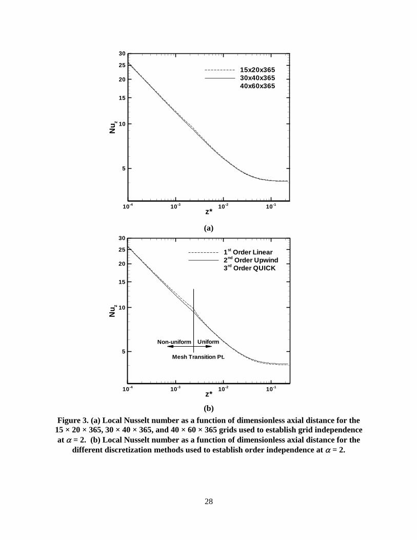
Grid Independence
Results were obtained with three different grids to establish grid-independence: 15 × 20 ×
365, 30 × 40 × 365, and 40 × 60 × 365 for channel aspect ratios of 2 and 10, and are shown in

11
Figure 3 (a). For = 2 the difference in local Nusselt number between the finest mesh and the
coarsest mesh at the first inlet cell was 48%; the typical difference over the domain length was
between 1% and 5%. The maximum difference between the medium mesh and the finest mesh
was less than 0.6%, and this difference was less than 0.1% over the majority of the domain
length. Similar results were observed for = 10.
Results from three different discretization schemes – first-order upwind, second-order
upwind, and third-order QUICK schemes [44] – were also compared for the 15 x 20 x 365 grid,
as shown in Figure 3 (b). The first-order and the second-order curves differed by as much as 5%
in the transition region and 1.5% in the fully developed region. Improving the discretization to a
third-order scheme resulted in no significant change over most of the channel and less than 1% in
a small part of the transition region. All quantities of interest were therefore solved on a 30 × 40
× 365 grid using a second-order approximation.
The numerical analysis was also verified to be independent of the geometric scale by
comparing results for a channel aspect ratio of = 2 at hydraulic diameters differing by a factor
of 100, but with identical dimensionless parameters. The difference in the calculated Nusselt
numbers was less than 0.5%.
Validation of Numerical Approach
Predictions from the numerical analysis are compared to analytical solutions for fully
developed Nusselt number Nufd and friction constant fRe. The method used to calculate these
values analytically for an arbitrary duct shape is described in Shah [30]; most of the original data
for various duct shapes reported in [3] were generated by this method. The z-momentum
equation is converted to the Laplace equation through a coordinate transformation, for which an
infinite series solution is available. For a finite number of terms, the coefficients in the series are
determined so that the error of the solution at an arbitrary number of points on the boundary is
minimized. The temperature field is then solved by a similar approach. For aspect ratios greater
than 8, the number of terms needed to accurately describe the velocity and temperature profile
makes matrix inversion for a least-squares solution difficult. The method of Householder
reflections was used to compute all the inversions robustly. Predictions from the present study
are compared in Table 3 to the analytical results obtained by this method and, where available, to
Shah’s tabulated data from [30]. For = 45° the predictions agree with the analytical results at

12
all aspect ratios to within 1.03% for Nufd and to within 0.51% for fRe. The analytical results
agree with those from [30] to within 0.46% for Nufd and to within 0.19% for fRe. For = 54.7°,
a few points exhibit discrepancies of up to 4% for fRe.
RESULTS AND DISCUSSION
Fully developed friction constants fRe were calculated for each channel aspect ratio using
the pressure drop across the entire channel length and are shown in Figure 4. For both channel
sidewall angles, = 54.7° and 45°, the aspect ratio is seen to have a significant effect on fRe.
For channels that are more triangular, i.e., as → 0, fRe is small (13~14), but for 1< <100, the
value of fRe increases approximately as log(). The upper limit of fRe = 24 (parallel plates) is
approached slowly as → ∞. These data agree well with [30] and with analytical solutions, as
compared in Table 3.
Local and average Nusselt numbers were calculated as a function of dimensionless axial
length for each aspect ratio, with the resulting families of curves for = 54.7° plotted in Figure 5
(a) and (b), respectively. For each curve in Figure 5 (a), the local Nusselt number in the entrance
region follows an exponential relationship with z*. Upon nearing the thermal development
length *
thL , a smooth transition to the fully developed value for the Nusselt number is apparent,
after which Nuz remains constant. The average Nusselt number Nuavg, plotted in Figure 5 (b),
follows a similar trend, but lags the local Nusselt number as expected; the fully developed value
is only approached asymptotically due to the prolonged influence of the high Nuz values in the
entrance region. These characteristics are consistent with the analytical solution for parallel
plates described above.
The curves for both local and average Nusselt number exhibit a clear correlation with
channel aspect ratio. The fully developed Nusselt number Nufd and the thermal development
length *
thL are the key parameters that change with channel aspect ratio a, as shown in Figure 6
for the 54.7° and the 45° sidewall angles. For both sidewall angles, *
thL is shown to decrease
from approximately 0.07 to 0.012 as channel aspect ratio is increased from 0 to ∞. The fully
developed Nusselt number increases from approximately 3 for triangular channels, up to 8 for
channels with large aspect ratios. Comparisons are given in Table 3 between numerically
determined values of Nufd from the present study, values of Nufd tabulated in [30] for 45°

13
sidewalls, and analytical solutions from the present work following the method of Shah [30].
Correlation equations for fRe, Nufd, and *
thL were obtained by means of a nonlinear least-
squares regression of the results calculated from the numerical model, applied to sigmoid
equation forms bearing either double exponential or arctangent functions, and are discussed
below.
Friction Constant Correlations
The friction constants fRe for channels with = 54.7° and 45° are correlated according to
Equations (9) and (12), respectively, which are listed in Table 4. The correlations are applicable
for a wide range of channel aspect ratios spanning from = 0 to approximately 1100, beyond
which the duct may be treated as a parallel-plates channel with fRe = 24. The mean absolute
errors of Equations (9) and (12) with respect to the numerical data are 0.25% for 45° sidewalls
and 1.20% for 54.7° sidewalls. Equations (9) and (12) are shown in Figure 4 along with the
numerically predicted values from this work. Also included are the experimental data of Wu and
Cheng [18], and the correlations from [18] and from Sadasivam, et al. [22] for = 54.7° and 45°,
respectively. Good agreement is noted between the present correlations and prior work. The
correlation of Wu and Cheng [18] for = 54.7° fits their experimental data well, but the limits at
= 0 and ∞ deviate from the theoretical values by up to 8%. The present correlation for = 45°
requires fewer constants than that of [22] to achieve excellent accuracy.
Nusselt Number Correlations
Fully developed Nusselt numbers Nufd for channels with = 54.7° and 45° are correlated
in terms of according to Equations (10) and (13), given in Table 4. Corresponding correlations
for the thermal entrance lengths *
thL are given in Equations (11) and (14). Each of these equations
is piecewise continuous, having three sections: constants at the very small and very large aspect
ratios, and an intervening sigmoid section fit to aspect ratios from 0.1 to approximately 200. The
mean absolute errors of the correlations with respect to the numerical computations are less than
0.5% for Nufd and less than 1.5% for *
thL . Equations (10) and (11) are plotted in Figure 6 (a)
along with the numerical predictions for channels with = 54.7°, while a similar plot with
Equations (13) and (14) is presented in Figure 6 (b) for channels with = 45°.

14
A new dimensionless coordinate , defined as
*
*
th th
z z
L L ,
may be used as a quantitative measure of the extent to which a flow has developed thermally. A
value of = 1 indicates nearly full thermal development, i.e., Nuz/Nufd = 1.05, which is an
arbitrary value recommended in the literature [3]. The magnitude of enhancement of local and
average Nusselt numbers for a given value of is shown from the present results to be
independent of channel aspect ratio, to a good approximation. The local and average Nusselt
numbers for a channel of any aspect ratio may therefore be reduced to functions only of and
Nufd. The correlations provided by Shah [29] for local and average Nusselt number can be
generalized in this manner, with minor adjustments to improve the accuracy, according to
Equations (15) and (16) in Table 4. Although from the numerical data, Nuz is found to vary as
to the power of an exponent that ranges between -0.31 and -0.35, a single exponent of -1/3 is
used in the first segment of Equations (15) and (16) to represent this dependence as dictated by
theoretical analysis for two-dimensional cases. The second segment of Equation (16) includes an
exponent of -0.29 to improve continuity between the first and third segments of Equation (16).
For trapezoidal microchannels with 54.7° sidewalls, Equations (10) and (11) are applied
along with Equations (15) and (16) to predict local and average Nusselt numbers as functions of
channel aspect ratio and normalized axial coordinate . These results are compared with Nuz and
Nuavg from the numerical analysis for representative aspect ratios of 1, 5, and 10 in Figure 7. The
correlations typically deviate from the numerical results by less than 2% to 3%, although the
discrepancies are higher for small (< 1) aspect ratios at very small values. Equation (15)
predicts Nuz to within 1.5% of the exact values known for parallel plates.
Comparison to Simultaneously Developing Flow
Thermally developing flow (TDF) is the condition assumed for predicting microchannel
heat transfer in all the results presented thus far, according to the recommendations of Lee, et al.
[8] and Phillips [10]. In practice, however, some extent of simultaneously developing flow
(SDF) is expected to be present in microchannel heat sinks. In SDF, the additional effect of
hydrodynamic boundary layer growth contributes to a higher Nusselt number in the entrance
15
region. The TDF assumption is essentially a high-Prandtl (Pr >> 1) assumption. For a Prandtl
number near unity, such as for most gases, or much less than unity, such as for liquid metals, the
importance of hydrodynamic boundary layer growth in the entrance region should be considered
as well.
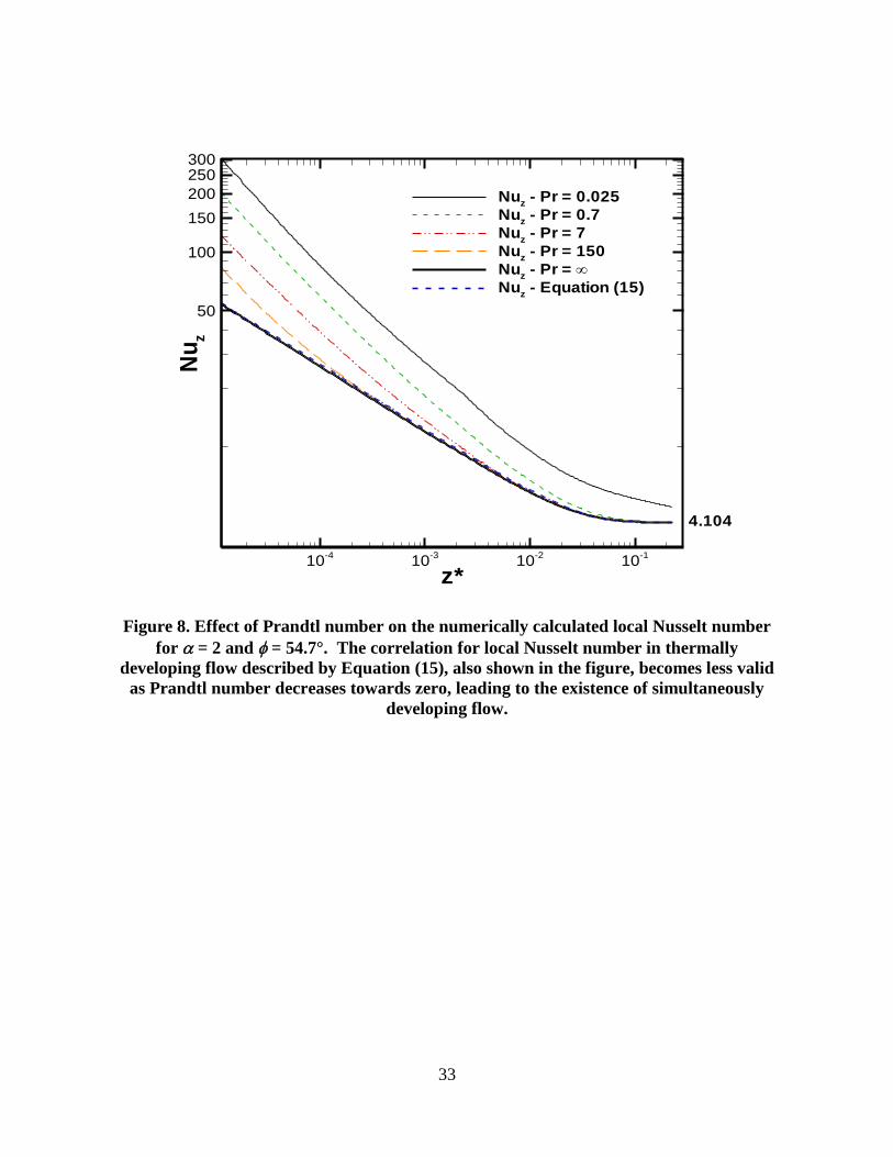
Simultaneously developing flow was simulated in a microchannel with = 2 and =
54.7° by applying a uniform (slug-flow) velocity profile at the inlet and setting fluid properties to
match the Prandtl number of four different fluids: ethylene glycol (Pr = 150), water (Pr = 7), air
(Pr = 0.74), and mercury (Pr = 0.025). Local Nusselt numbers for these fluids computed using
SDF assumptions are compared to the TDF case in Figure 8. The comparison indicates that
hydrodynamic boundary layer development provides an additional enhancement of local Nusselt
number. For design problems in which the temperature of the wall rather than that of the fluid is
of primary interest, the TDF assumption provides a conservative (lower) estimate for local and
average Nusselt numbers in the entrance region. Since the TDF model has resulted in good
agreement between experiment and simulation in microchannel heat sinks ([8] and [10]), the
TDF assumption is still suitable in general for liquid flow in microchannels, for which Equations
(15) and (16) are recommended.
CONCLUSIONS
Numerical results are obtained and summarized for thermally developing flow (TDF)
with the H1 boundary condition in trapezoidal microchannels with sidewall angles 54.7° and
45° over a wide range of aspect ratios. Using carefully constructed grids, local and average heat
transfer coefficients in the entrance region of these 3-dimensional channels are found to be
proportional to 1/3( )z
in the entrance region, which is identical to the proportionality predicted
by the 2-D Graetz-Lévêque solutions. Changing the aspect ratio α or sidewall angle of the
channel affects both the fully developed value of Nusselt number Nufd and the thermal entrance
length *
thL . Normalization of the axial length variable z* by *
thL and the local Nusselt number
Nuz by Nufd allows the modification of Shah’s [29] thermally developing flow correlations for
application to the trapezoidal channels considered here; these new correlations for local and
average Nusselt numbers are given in Equations (15) and (16).
16
Acknowledgment
The authors thank the members of the Cooling Technologies Research Center, a National
Science Foundation Industry/University Cooperative Research Center at Purdue University, for
their financial support. Technical discussions with Dr. Jayathi Murthy and Dr. Poh-Seng Lee are
also gratefully acknowledged.
REFERENCES
[1] E. Vazsonyi, Z. Vertesy, A. Toth, J. Szlufcik, Anisotropic etching of silicon in a two-
component alkaline solution, J. Micromech. Microeng. 13 (2003) 165-169.
[2] Virginia Semiconductor Inc., Wet chemical etching and cleaning of silicon, Virginia
Semiconductor Inc., Fredericksburg, VA, 2003.
[3] R.K. Shah, A.L. London, Laminar Flow Forced Convection in Ducts: A Source Book for
Compact Heat Exchanger Analytical Data, Academic Press, New York, 1978.
[4] S. Kakaç, R.K. Shah, W. Aung (Eds.), Handbook of Single-Phase Convective Heat
Transfer, Wiley, New York, 1987, pp. 3.10-3.121.
[5] D.B. Tuckerman, R.F.W. Pease, High-performance heat sinking for VLSI, IEEE Electron
Device Letters 2 (1981) 126-129.
[6] J. Judy, D. Maynes, B.W. Webb, Characterization of frictional pressure drop for liquid
flows through microchannels, Int. J. Heat Mass Transfer 45 (2002) 3477-3489.
[7] D. Liu, S.V. Garimella, Investigation of liquid flow through microchannels, AIAA J.
Thermophys. Heat Transfer 18 (2004) 65-72.
[8] P.S. Lee, D. Liu, S.V. Garimella, Investigation of heat transfer in rectangular
microchannels, Int. J. Heat Mass Transfer 48 (2005) 1688-1704.
[9] R.K. Shah, Compact Heat Exchangers, in: W.M. Rohsenow, J.P. Hartnett, E.N. Ganić
(Eds.), Handbook of Heat Transfer Applications McGraw-Hill, New York, 1985, pp.
4.217-4.218.
[10] R.J. Phillips, Microchannel Heat Sinks, in: A. Bar-Cohen, A.D. Kraus (Eds.), Advances
in Thermal Modeling of Electronic Components and Systems 2, ASME Press, New York,
1990, pp. 109-184.

17
[11] J. Harley, H. Bau, J.N. Zemel, V. Dominko, Fluid flow in micron and submicron size
channels, Proc. IEEE Micro Electro Mechanical Systems: An Investigation of Micro
Structures, Sensors, Actuators, Machines and Robots, 1989, pp. 25-28.
[12] S.M. Flockhart, R.S. Dhariwal, Experimental and numerical investigation into the flow
characteristics of channels etched in <100> silicon, J. Fluids Eng. 120 (1998) 291-295.
[13] B. Farhanieh, B. Sunden, Three-dimensional laminar flow and heat transfer in the
entrance region of trapezoidal ducts, Int. J. Num. Meth. Fluids 13 (1991) 537-556.
[14] J.R. Rujano, M.M. Rahman, Analysis and computation of conjugate heat transfer in
trapezoidal microchannel heat sinks in a silicon substrate, ASME Heat Transfer Division,
HTD 305, Heat Transfer in Microgravity Systems (1997) 175-185.
[15] W. Qu, G.M. Mala, D. Li, Heat transfer for water flow in trapezoidal silicon
microchannels, Int. J. Heat Mass Transfer 43 (2000) 3925-3936.
[16] W. Qu, G.M. Mala, D. Li, Pressure-driven water flows in trapezoidal silicon
microchannels, Int. J. Heat Mass Transfer 43 (2000) 353-364.
[17] M.M. Rahman, S.S. Shevade, Fluid flow and heat transfer in a composite trapezoidal
microchannel, Proc. 2005 ASME Summer Heat Transfer Conference, 2005, pp. 411-417.
[18] H.Y. Wu, P. Cheng, Friction factors in smooth trapezoidal silicon microchannels with
different aspect ratios, Int. J. Heat Mass Transfer 46 (2003) 2519-2525.
[19] H.Y. Wu, P. Cheng, An experimental study of convective heat transfer in silicon
microchannels with different surface conditions, Int. J. Heat Mass Transfer 46 (2003)
2547-2556.
[20] S. Chen, T.L. Chan, C.W. Leung, B. Yu, Numerical prediction of laminar forced
convection in triangular ducts with unstructured triangular grid method, Numerical Heat
Transfer, Part A: Applications 38 (2000) 209-224.
[21] J.T. Dickey, T.T. Lam, Heat transfer in triangular microchannels, Advances in Electronic
Packaging 2 (2003) 303-307.
[22] R. Sadasivam, R.M. Manglik, M.A. Jog, Fully developed forced convection through
trapezoidal and hexagonal ducts, Int. J. Heat Mass Transfer 42 (1999) 4321-4331.
[23] M. Bahrami, M.M. Yovanovich, J.R. Culham, Pressure drop of fully-developed, laminar
flow in microchannels of arbitrary cross-section, Proc. 3rd International Conf. on
Microchannels and Minichannels, 2005, pp. 269-280.
18
[24] M. Bahrami, M.M. Yovanovich, J.R. Culham, Pressure drop of fully-developed, laminar
flow in rough microtubes, Proc. 3rd International Conf. on Microchannels and
Minichannels, 2005, pp. 259-268.
[25] M. Bahrami, M.M. Yovanovich, J.R. Culham, Convective heat transfer of laminar,
single-phase flow in randomly rough microtubes, Proc. 2005 ASME International
Engineering Congress and Exposition, 2005, pp. 449-457.
[26] M.E. Steinke, S.G. Kandlikar, Single-phase liquid friction factors in microchannels, 3rd
International Conference on Microchannels and Minichannels, Elsevier France-Editions
Scientifiques Medicales Elsevier, 2005, pp. 1073-1083.
[27] M. Rokni, B. Sunden, Numerical investigation of turbulent forced convection in ducts
with rectangular and trapezoidal cross-section area by using different turbulence models,
Numerical Heat Transfer, Part A: Applications 30 (1996) 321 - 346.
[28] X. Wei, Y. Joshi, Stacked microchannel heat sinks for liquid cooling of microelectronic
components, J. Electronic Packaging 126 (2004) 60-66.
[29] R.K. Shah, Thermal entry length solutions for the circular tube and parallel plates, Proc.
3rd National Heat and Mass Transfer Conf. 1, 1975, Pap. No. HMT-11-75.
[30] R.K. Shah, Laminar flow friction and forced convection heat transfer in ducts of arbitrary
geometry, Int. J. Heat Mass Transf. 18 (1975) 849-862.
[31] P.S. Lee, S.V. Garimella, Thermally developing flow and heat transfer in rectangular
microchannels of different aspect ratios, Int. J. Heat Mass Transfer 49 (2006) 3060-3067.
[32] P. Talukdar, M. Shah, Analysis of Laminar Mixed Convective Heat Transfer in
Horizontal Triangular Ducts, Numerical Heat Transfer, Part A: Applications 54 (2008)
1148 - 1168.
[33] M. Renksizbulut, H. Niazmand, Laminar flow and heat transfer in the entrance region of
trapezoidal channels with constant wall temperature, J. Heat Transfer 128 (2006) 63-74.
[34] H. Niazmand, M. Renksizbulut, E. Saeedi, Developing slip-flow and heat transfer in
trapezoidal microchannels, Int. J. Heat Mass Transf. 51 (2008) 6126-6135.
[35] G. Wang, L. Hao, P. Cheng, An experimental and numerical study of forced convection
in a microchannel with negligible axial heat conduction, Int. J. Heat Mass Transf. 52
(2009) 1070-1074.

19
[36] L. Graetz, On the thermal conductivity of liquids, Part 1, Ann. Phys. Chem. 18 (1883) 79-
94.
[37] L. Graetz, On the thermal conductivity of liquids, Part 2, Ann. Phys. Chem. 25 (1885)
337-357.
[38] W.M. Kays, Numerical solutions for laminar-flow heat transfer in circular tubes, Trans.
ASME 77 (1955) 1265-1274.
[39] L.M. Lévêque, The laws of heat transmission by convection, Les Annales des Mines:
Memoires 12-13 (1928) 201-299, 305-362, 381-415.
[40] W. Nusselt, Heat exchange in sprinkler coolers, VDI Z 67 (1923) 206-210.
[41] B.S. Petukhov, C. Chzhen-Yun, Heat transfer in the hydrodynamic inlet region of a round
tube with laminar flow, Proc. 2nd All Soviet Union Conf. Heat and Mass Transfer 1
(1964) 193-204, English Trans. J. C. Gazley, J.P. Hartnett, E.R.G. Eckert (Eds.), Rand
Corp., Santa Monica, CA, Rep. R-451-PR, 1966.
[42] R. Siegel, E.M. Sparrow, T.M. Hallman, Steady laminar heat transfer in a circular tube
with prescribed wall heat flux, Appl. Sci. Res., Sect. A 7 (1958) 386-392.
[43] E.M. Sparrow, J.L. Novotny, S.H. Lin, Laminar flow of a heat-generating fluid in a
parallel-plate channel, AIChE J. 9 (1963) 797-804.
[44] Fluent, Inc., FLUENT 6.2 user's guide, Fluent, Inc., Lebanon, NH, 2005.
[45] F.M. White, Viscous Fluid Flow, 2nd ed., McGraw-Hill, New York, 1991, ch. 3.

20
LIST OF TABLES
Table 1. Comparison of studies in the literature applicable to thermally developing flow in
trapezoidal microchannels.
Table 2. Test matrix for numerical simulations of microchannels with = 54.7° and 45°.
Table 3. Values of Nufd and fRe from present method compared with those of Shah [30] and
analytical values.
Table 4. Correlations for friction constant, fully developed Nusselt number, thermal entrance
length, local Nusselt number, and average Nusselt number in thermally developing flow with
the H1 boundary condition.

21
Tab
le 1
. C
om
pari
son
of
stu
die
s in
th
e li
tera
ture
ap
pli
cab
le t
o t
her
mall
y d
evel
op
ing f
low
in
tra
pez
oid
al
mic
roch
an
nel
s.
Co
rrel-
ati
on
?
Yes
Plo
ts
Dis
cre
te
Data
Plo
ts
Dis
c.
Data
Dis
c.
Data
Yes
Dis
c.
Data
Dis
c.
Data
Dis
c.
Data
Dis
c.
Data
Dis
c.
Data
Plo
ts
Yes
Yes
Yes
Plo
ts
Yes
Plo
ts
Flo
w C
on
dit
ion
s C
on
sid
ere
d
Lam
inar,
Therm
ally
Develo
pin
g
Lam
inar,
Fully
Deve
lop
ed
Lam
inar
Lam
inar,
Hyd. D
eve
lopin
g f
Re
,
Fully
Develo
pe
d N
u
Lam
inar,
Sim
. D
evelo
pin
g
Lam
inar,
Fully
Deve
lop
ed
Lam
nia
r, F
ully
Deve
lop
ed
Lam
inar,
Surf
ace R
ough
ne
ss
Lam
inar,
Fully
Dev., Ⓣ
, H
1
Lam
inar,
Surf
ace R
ough
ne
ss
Lam
inar,
Aspect
Ratio E
ffe
ct
Lam
nia
r, S
urf
ace C
ond
itio
ns
Turb
ule
nt, T
herm
ally
Develo
pin
g
Lam
inar,
Fully
Deve
lop
ed
Lam
inar,
Therm
ally
Develo
pin
g
Lam
inar,
Sim
ulta
neo
usly
Develo
pin
g, Ⓣ
Lam
inar,
Sim
ulta
neo
usly
Develo
pin
g,
Mix
ed C
onvection
Lam
inar,
Sim
. D
ev., S
lip f
low
w/ K
n ≤
0.1
, Ⓣ
Lam
inar,
Sim
. D
ev., 1
hea
ted
wall
Meth
od
Ana
lytica
l,
Num
eri
cal
Num
eri
cal
Experi
men
tal
Num
eri
cal
Exp., N
um
.
Exp., N
um
.
Num
eri
cal
Experi
men
tal
Num
eri
cal
Experi
men
tal
Experi
men
tal
Experi
men
tal
Exp., N
um
.
Ana
lytica
l, A
ppro
x.
Exp., N
um
.
Num
eri
cal
Num
eri
cal
Num
eri
cal
Exp., N
um
.
Nu
×
× ×
× ×
×
× ×
× ×
×
×
×
×
fRe
×
×
×
×
×
×
× ×
×
× × × ×
Ch
an
nel
Sh
ap
e
Para
llel P
late
s, C
ircula
r P
ipes
Tra
pezoid
al D
ucts
,
=
30°,
45°,
60
°, e
tc.
Tra
pezoid
al M
icro
chann
els
,
=
45°,
54.7
°
Tra
pezoid
al D
ucts
,
=
30°,
45°,
60
°, e
tc.
Tra
pezoid
al M
icro
ch., =
54.7
°
Tra
pezoid
al M
icro
chann
els
,
=
45°,
54.7
°
Tra
pezoid
al D
ucts
,
=
30°,
45°,
60
°, 7
5°
Tra
pezoid
al M
icro
ch., =
54.7
°
Triang
ula
r D
ucts
, =
45
°, 6
0°,
75°,
82.5
°
Tra
pezoid
al M
icro
ch., =
54.7
°
Tra
pezoid
al M
icro
ch., =
54.7
°
Tra
pezoid
al M
icro
ch., =
54.7
°
Tra
pezoid
al M
icro
ch., =
54.7
°
Arb
itra
ry
Recta
ng
ula
r M
icro
ch
ann
els
Tra
p. M
icro
ch., =
30°,
45°,
60°,
90°,
α =
0.5
, 1.0
, 2.0
Triang
ula
r D
ucts
,
=
45°,
60°,
75
°
Tra
p. M
icro
ch., =
30°,
45°,
60°,
90°,
α =
0.2
5 ~
2.0
Tra
pezoid
al M
icro
ch., =
30°
Yea
r
1975
1975
1989
1991
1997
1998
1999
2000
2000
2000
2003
2003
2005
2005
2006
2006
2008
2008
2009
Au
tho
r(s)
Sha
h [2
9]
Sha
h [3
0]
Harley, e
t a
l.
[11]
Farh
an
ieh &
Sun
den [
13]
Ruja
no &
Ram
an [1
4]
Flo
ckhart
&
Dhariw
al [1
2]
Sad
asiv
am
, et
al. [
22]
Qu, et a
l. [
15]
Chen,
et
al. [
20]
Qu, et a
l. [
16]
Wu &
Ch
eng
[18]
Wu &
Ch
eng
[19]
Rahm
an &
Sheva
de [
17]
Bahra
mi, e
t al.
[23]
Lee &
Garim
ella
[3
1]
Renksiz
bu
lut
&
Nia
zm
and [
33]
Talu
kdar
&
Sha
h [3
2]
Nia
zm
and,
et
al. [3
4]
Wan
g, e
t a
l.
[35]

22
Table 2. Test matrix for numerical simulations of microchannels with = 54.7° and 45°.
2a
/ (m)
2b
/ (m)
0 0 250
0.05 12.5 250
0.1 25 250
0.5 125 250
0.75 93.75 250
1 250 250
1.5 375 250
2 500 250
3 750 250
4 1,000 250
5 1,250 250
6 1,500 250
7 1,750 250
8 2,000 250
10 2,500 250
20 5,000 250
50 12,500 250
100 25,000 250

23
Table 3. Values of Nufd and fRe from present method compared with those of Shah [30]
and analytical values.
fRe
Shah, 45°
[30]
present, 45° present, 54.7°
Analyt. A./S Numer. N/A. Analyt. Numer. F/A
0.05 13.241 13.223 -0.13% 13.509 13.492 -0.12%
0.1 13.290 13.293 0.03% 13.623 13.592 -0.23%
0.25 13.323 13.324 0.01% 13.333 0.06% 13.691
0.5 13.364 13.369 0.03% 13.374 0.04% 13.654 13.639 -0.11%
0.75 13.541 13.544 0.02% 13.557 0.10% 13.785 13.772 -0.09%
1 13.827 13.822 -0.04% 13.831 0.07% 14.064 14.180 0.83%
1.5 14.508 14.511 0.02% 14.802 14.780 -0.15%
2 15.206 15.212 0.04% 15.201 -0.07% 15.566 15.541 -0.16%
3 16.447 16.425 -0.13% 16.879 17.293 2.45%
4 17.397 17.420 0.13% 17.389 -0.18% 17.881 17.545 -1.88%
5 18.184 18.149 -0.20% 18.650 18.680 0.16%
6 18.796 18.755 -0.22% 19.252 19.207 -0.23%
7 19.294 19.250 -0.23% 19.736 19.678 -0.29%
8 19.743 19.706 -0.19% 19.659 -0.24% 20.131 20.068 -0.31%
10 20.349 20.296 -0.26% 20.737 20.658 -0.38%
20 21.915 21.837 -0.36% 22.174 21.520 -2.95%
50 23.087 22.968 -0.51% 23.212 22.360 -3.67%
100 23.521 23.405 -0.49% 23.590 23.471 -0.50%
Nufd
Shah, 45°
[30]
present, 45° present, 54.7°
Analyt. A./S Numer. N/A. Analyt. Numer. F/A
0.05 3.005 3.033 0.93% 3.146 3.170 0.76%
0.1 3.023 3.054 1.03% 3.188 3.221 1.03%
0.25 3.048 3.049 0.03% 3.079 0.99% 3.246
0.5 3.081 3.080 -0.04% 3.107 0.89% 3.261 3.285 0.74%
0.75 3.155 3.155 0.01% 3.188 1.03% 3.319 3.341 0.67%
1 3.268 3.272 0.13% 3.304 0.96% 3.431 3.465 0.97%
1.5 3.569 3.602 0.91% 3.739 3.748 0.24%
2 3.888 3.886 -0.06% 3.907 0.56% 4.073 4.104 0.76%
3 4.464 4.484 0.45% 4.678 4.697 0.40%
4 4.943 4.933 -0.20% 4.949 0.32% 5.160 5.198 0.75%
5 5.307 5.323 0.30% 5.536 5.555 0.36%
6 5.609 5.624 0.27% 5.833 5.849 0.27%
7 5.856 5.874 0.30% 6.073 6.092 0.31%
8 6.034 6.062 0.46% 6.081 0.31% 6.271 6.289 0.29%
10 6.383 6.406 0.36% 6.575 6.599 0.36%
20 7.173 7.211 0.53% 7.302 7.351 0.67%
50 7.769 7.821 0.68% 7.830 7.867 0.47%
100 8.015 8.029 0.18% 8.027 8.056 0.36%

24
Table 4. Correlations for friction constant, fully developed Nusselt number, thermal
entrance length, local Nusselt number, and average Nusselt number in thermally
developing flow with the H1 boundary condition.
s Qty Correlation Equation Limits Eq No.
MAEa
(%)
54.7°
fRe 13.35 10.74exp exp 0.85 ln( ) 1.25 0 1100 (9) 1.20
Nufd
3.121
3.265 5.075exp exp 0.9041 ln( ) 1.3496
8.235
0 0.1
0.1 250
250
(10) 0.40
*
thL 1
0.07227
0.04221 0.02192 tan 1.3578 ln( ) 0.9560
0.01154
0 0.1
0.1 200
200
(11) 1.30
45°
fRe 13.35 10.74exp exp 0.86 ln( ) 1.35 0 1100
(12) 0.25
Nufd
3.032
3.093 5.322exp exp 0.8494 ln( ) 1.4353
8.235
0 0.1
0.1 220
220
(13) 0.40
*
thL
0.07778
0.07637 0.06503exp exp 1.1974 ln( ) 0.6610
0.01154
0 0.1
0.1 220
220
(14) 1.40
s Qty Correlation Equation Limits Eq No.
Typ. Error
b
(%)
54.7° and 45°
th
z
L
, ( ) 1.05z th fdNu L Nu
z
fd
Nu
Nu
1/3
0.318
0.506 1.992
0.786
0.843
1 0.298 e
0 0.008
0.008 0.08
0.08
(15) 2.0
avg
fd
Nu
Nu
1/3
0.29
1.048
1.203
1 0.2189
0 0.04
0.04 0.8
0.8
(16) 3.1
a“MAE” refers to “mean absolute error” of the correlation with respect to the numerical data.
b“Typ. Error” refers to typical error, a weighted average absolute percent value of the discrepancy between the
correlation and the numerical data, with less weight being given to very small values of .

25
LIST OF FIGURES
Figure 1. Exact solution for local, average, and mean Nusselt numbers in the parallel-plates
thermal entrance problem. The tabulated data of Shah [29] for local and mean Nusselt numbers
are shown as superposed symbols.
Figure 2. (a) Generalized trapezoidal duct cross-sectional parameters. The computational
domain is shown with a bold dashed line. The sidewall angles in the present work are 54.7°
and 45°. (b) Numerical mesh at the entrance of the duct showing the half-channel
computational domain. Central cells are large and cells near the wall are small in x and y, while
every cell is small in z near the entrance. The mesh becomes uniform by the end of the thermal
development region. The 15 x 20 x 365 mesh is shown for clarity, although a finer mesh (30 ×
40 × 365) is used in the computations.
Figure 3. (a) Local Nusselt number as a function of dimensionless axial distance for the 15 × 20
× 365, 30 × 40 × 365, and 40 × 60 × 365 grids used to establish grid independence at = 2. (b)
Local Nusselt number as a function of dimensionless axial distance for the different
discretization methods used to establish order independence at = 2.
Figure 4. Variation of fully developed friction factor with channel aspect ratio for trapezoidal
channels of various aspect ratios. Included are the numerical results from the present work, the
correlation equations (9) and (12) from the present work, the experimental data of Wu and
Cheng [18], and the correlations from [18] and Sadasivam, et al. [22] for = 54.7° and 45°,
respectively.
Figure 5. Numerical results of (a) local and (b) average Nusselt number as a function of axial
location for = 54.7°. Dimensionless thermal development lengths (*
thL ) are shown for the two
limiting cases in Figure (a).
Figure 6. Variation of thermal development length (left axis) and fully developed Nusselt
number (right axis) with channel aspect ratio for trapezoidal channels with sidewall angle of (a)
54.7°, and (b) 45°.
Figure 7. Representative predictions from Equations (15) and (16) for Nuz and Nuavg,
respectively, at selected aspect ratios for = 54.7°, compared to numerical results.
Figure 8. Effect of Prandtl number on the numerically calculated local Nusselt number for = 2
and = 54.7°. The correlation for local Nusselt number in thermally developing flow described
by Equation (15), also shown in the figure, becomes less valid as Prandtl number decreases
towards zero, leading to the existence of simultaneously developing flow.
26
z*
Nu
10-5
10-4
10-3
10-2
10-1
100
10
30
50
70
90
110
130150
Nuz
Nuavg
Num
Nuz
- Shah [29]
Num
- Shah [29]
8.2353
Figure 1. Exact solution for local, average, and mean Nusselt numbers in the parallel-
plates thermal entrance problem. The tabulated data of Shah [29] for local and mean
Nusselt numbers are shown as superposed symbols.

27
2b
2a
q
2
2
a
b
(a)
x (m)
0
0.0001
0.0002
0.0003
0.0004
0
5E-05
0.0001
0.00015
0.0002
0.00025
y(m
)
(b)
Figure 2. (a) Generalized trapezoidal duct cross-sectional parameters. The
computational domain is shown with a bold dashed line. The sidewall angles in the
present work are 54.7° and 45°. (b) Numerical mesh at the entrance of the duct showing
the half-channel computational domain. Central cells are large and cells near the wall
are small in x and y, while every cell is small in z near the entrance. The mesh becomes
uniform by the end of the thermal development region. The 15 x 20 x 365 mesh is shown
for clarity, although a finer mesh (30 × 40 × 365) is used in the computations.
28
z*
Nu
z
10-4
10-3
10-2
10-1
5
10
15
20
25
30
15x20x365
30x40x365
40x60x365
(a)
z*
Nu
z
10-4
10-3
10-2
10-1
5
10
15
20
25
30
1st
Order Linear
2nd
Order Upwind
3rd
Order QUICK
Uniform
Mesh Transition Pt.
Non-uniform
(b)
Figure 3. (a) Local Nusselt number as a function of dimensionless axial distance for the
15 × 20 × 365, 30 × 40 × 365, and 40 × 60 × 365 grids used to establish grid independence
at = 2. (b) Local Nusselt number as a function of dimensionless axial distance for the
different discretization methods used to establish order independence at = 2.

29
fRe
10-2
10-1
100
101
102
10312
14
16
18
20
22
24
26
28fRe = 54.7° - Numerical
fRe - Equation (9)
fRe - Wu and Cheng Experiment [18]
fRe - Wu and Cheng Correlation [18]
fRe = 45° - Numerical
fRe - Equation (12)
fRe - Sadasivam, et al. Correlation [22]
Figure 4. Variation of fully developed friction factor with channel aspect ratio for
trapezoidal channels of various aspect ratios. Included are the numerical results from
the present work, the correlation equations (9) and (12) from the present work, the
experimental data of Wu and Cheng [18], and the correlations from [18] and Sadasivam,
et al. [22] for = 54.7° and 45°, respectively.

30
z*
Nu
z
10-5
10-4
10-3
10-2
10-1
100
10
30
50
70
90
110130150
= = 100 = 20 = 10 = 6 = 4 = 2 = 1 = 0.1 = 0
8.2353
3.1208
L*th
= 0.0732L*th
= 0.0121
(a)
z*
Nu
avg
10-5
10-4
10-3
10-2
10-1
100
50
100
150
= = 100 = 20 = 10 = 6 = 4 = 2 = 1 = 0.1 = 0
(b)
Figure 5. Numerical results of (a) local and (b) average Nusselt number as a function of
axial location for = 54.7°. Dimensionless thermal development lengths (*
thL ) are shown
for the two limiting cases in Figure (a).

31
L* th
Nu
fd
10-2
10-1
100
101
102
103
0
0.02
0.04
0.06
0.08
0
1
2
3
4
5
6
7
8
9
L*th
- Numerical
Nufd
- Numerical
L*th
- Equation (11)
Nufd
- Equation (10)
0.01154
250
< 250
3.121
< 0.1
0.1
200
< 200
0.072278.235
(a)
L* th
Nu
fd
10-2
10-1
100
101
102
103
0
0.02
0.04
0.06
0.08
0.1
0
2
4
6
8
10
L*th
- Numerical
Nufd
- Numerical
L*th
- Equation (14)
Nufd
- Equation (13)
< 220
220
0.07778
0.1
< 0.1
3.033
8.2353
0.01154
(b)
Figure 6. Variation of thermal development length (left axis) and fully developed Nusselt
number (right axis) with channel aspect ratio for trapezoidal channels with sidewall
angle of (a) 54.7°, and (b) 45°.

32
z*
Nu
10-5
10-4
10-3
10-2
10-1
10
30
50
70
90
110130150
Nuz
- Numerical
Nuavg
- Numerical
Nuz
- Equation (15)
Nuavg
- Equation (16)
= 10
= 1
= 5
3.436
5.567
8.079
Figure 7. Representative predictions from Equations (15) and (16) for Nuz and Nuavg,
respectively, at selected aspect ratios for = 54.7°, compared to numerical results.
33
z*
Nu
z
10-4
10-3
10-2
10-1
50
100
150
200
250300
Nuz
- Pr = 0.025
Nuz
- Pr = 0.7
Nuz
- Pr = 7
Nuz
- Pr = 150
Nuz
- Pr =
Nuz
- Equation (15)
4.104
Figure 8. Effect of Prandtl number on the numerically calculated local Nusselt number
for = 2 and = 54.7°. The correlation for local Nusselt number in thermally
developing flow described by Equation (15), also shown in the figure, becomes less valid
as Prandtl number decreases towards zero, leading to the existence of simultaneously
developing flow.