Embed Size (px)
Citation preview

CHAPTER
ONE
TRANSPORT IN MICROCHANNELS –A CRITICAL REVIEW
S. V. Garimella and C. B. Sobhan
ABSTRACT
The tremendous enhancement in heat transport obtained by employing microchannelshas provided an effective alternative to conventional methods of heat dissipation, espe-cially in applications related to cooling of microelectronics. A number of theoreticaland experimental studies have been reported on the fluid flow and heat transfer mecha-nisms in mini and microchannels as well as microtubes. Anomalies and deviations fromthe behavior expected for conventional channels, both in terms of the frictional and heattransfer characteristics have been noticed in microchannels under specific flow conditionsand flow regimes. The present work compiles and analyzes the results of the importantinvestigations on fluid flow and heat transfer in microchannels and microtubes.
1-56700-190-4/2003/$00+ $0.50c© 2003 by Begell House, Inc. 1
2 ANNUAL REVIEW OF HEAT TRANSFER, VOL. 13
NOMENCLATURE
A Channel aspect ratio (Hc/2Wc)Ac Cross-sectional areaAs Surface areaB Width of the slot nozzle for liquid impingement, mC, Cp Coolant specific heat, J/kg Kca Acoustic velocityc0 Concentration, molD Inside diameter, mDe, Dh Hydraulic diameter, mCFOM Coolant Figure of MeritF C Re[1− (d/d0)2] in Eq. (8), with empirical constantC = 7.6 · 10−5 and
d0 = 1.164 mmf Friction factorG Mass velocity, kg/m2sec (≡ m, mass flux)H, Hc Microchannel height, mhf g Latent heat of vaporization, J/kgjH Colburn J-factor [hcPr2/3/VρCp]kc Coolant thermal conductivity, w/m KL Heated length of heat sink channel, m; also channel length in Eq. (15)Nu Nusselt numberNux Local Nusselt numberNuGn Nusselt number from Gnielinski correlationPr Prandtl numberP Channel pitchPT Pumping power, W∆Pexp Experimental pressure drop, N/m2
∆Ppred Predicted pressure drop, N/m2
qm,p critical heat flux based on heated channel inside area, W/m2
Q Volumetric flow rateR Thermal resistance of a cross section, K/WRe Reynolds numberRecri Transition Reynolds numberRth 1D Thermal resistance from one-dimensional analysis, K/WRth 3D Thermal resistance from three-dimensional analysis, K/WR∗ Overall allowable thermal resistance between the entrance and the exit,
K/Wr Non-dimensional thermal resistance of a cross section (WTkf LR/Hc)s Heat spread effectTi Inlet temperaturet Tube wall thicknessv Inlet velocityV Fluid velocity, m/sec

TRANSPORT IN MICROCHANNELS – A CRITICAL REVIEW 3
W Microchannel width, mWc Center to center distance of microchannel, mWe Weber number, [G2L(σρ f )]WT Chip width, mw Half distance between adjacent channels, non-dimensionalized with chan-
nel heightwc Half channel width, non-dimensionalized with channel heightX Mole fractionx Lateral distance from stagnation point, mxL Equilibrium quality at the end of the channel heated lengthZ min(H,W)/max(H,W) in Eq. (7)µ Dynamic viscosity, kg/m secν Kinematic viscosityΦ Enhancement ratioρ Density, kg/m3
ρ f Density of liquid, kg/m3
σ Surface tension, N/mθ Angular coordinate, deg.ξc Zeta potential, V
1 INTRODUCTION
The continued increase in the functionality and compactness of microelectronics hascalled for novel methods for effective removal of the high heat fluxes associated withthese devices. The small sizes of the heat-dissipating devices and the very stringentoperational temperature requirements make thermal management of microelectronicdevices a challenging problem. Various cooling techniques such as impinging jetsand heat pipes have been applied to achieve effective heat removal, at the device andsystem levels. The use of microchannel heat sinks is a promising alternative whichcan provide much higher heat removal rates and may also be integrated directly intothe heat-dissipating substrates. The two important objectives in electronics cooling,namely the reduction of the device maximum temperature and the minimization oftemperature gradients on the device surface, can be efficiently achieved by the use ofmicrochannel heat sinks.
It has been observed that microchannel heat sinks can dissipate heat loads as highas 1000 W/cm2 with maximum surface temperatures of less than 120◦ [1]. Thepossibility of achieving this level of heat dissipation has lead resulted in a number ofstudies on the application of microchannel flow to the cooling of high power densitysystems. Some of the investigations focussed on understanding the fundamentalsof microchannel flow, and on comparing and contrasting the flow and heat transfercharacteristics in microchannels with those in conventional channels. Theoreticalanalyses leading to optimization of microchannel heat sinks were carried out; so alsowere experimental investigations to obtain new correlations and to extend the range
4 ANNUAL REVIEW OF HEAT TRANSFER, VOL. 13
of application of large-channel correlations to include microchannels. Single-phaseliquid and air flow, boiling, and multiphase flow in microchannels have all beeninvestigated. Other studies have addressed fluid flow and heat transfer
in very small tubes and mini channels.Theoretical and experimental investigations reported over the past decade in fluid
flow and heat transfer in microchannels are reviewed in this work. Application ofmicrochannel cooling to electronic devices and other heat exchange systems is ex-amined. Important correlations that were proposed from original research and ob-tained by modifying existing large-channel correlations are summarized. Studies inthe literature on design, testing and optimization of microchannel heat sinks are alsodiscussed.
2 MICROCHANNEL CONCEPTS AND EARLY WORK
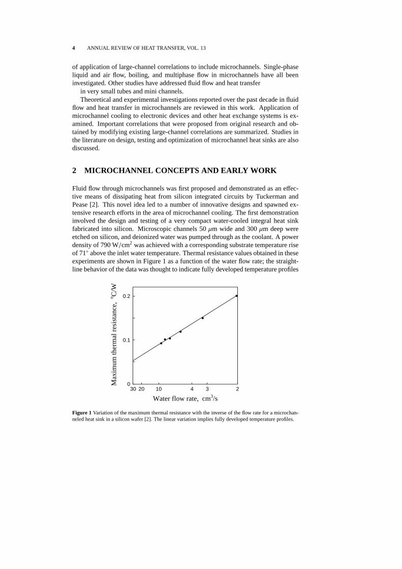
Fluid flow through microchannels was first proposed and demonstrated as an effec-tive means of dissipating heat from silicon integrated circuits by Tuckerman andPease [2]. This novel idea led to a number of innovative designs and spawned ex-tensive research efforts in the area of microchannel cooling. The first demonstrationinvolved the design and testing of a very compact water-cooled integral heat sinkfabricated into silicon. Microscopic channels 50µm wide and 300µm deep wereetched on silicon, and deionized water was pumped through as the coolant. A powerdensity of 790 W/cm2 was achieved with a corresponding substrate temperature riseof 71◦ above the inlet water temperature. Thermal resistance values obtained in theseexperiments are shown in Figure 1 as a function of the water flow rate; the straight-line behavior of the data was thought to indicate fully developed temperature profiles
Water flow rate, cm3/s
234102030
Max
imum
ther
mal
resi
stan
ce,
o C/W
0
0.1
0.2
Figure 1 Variation of the maximum thermal resistance with the inverse of the flow rate for a microchan-neled heat sink in a silicon wafer [2]. The linear variation implies fully developed temperature profiles.
TRANSPORT IN MICROCHANNELS – A CRITICAL REVIEW 5
in the microchannels.In a sequel to this work, Tuckerman and Pease [3] discussed the problems as-
sociated with coolant selection, packaging and headering, microstructure selection,fabrication and bonding, and described some successful strategies for forced convec-tion cooling using microchannels. To optimize the heat transfer coefficient at a givencoolant pressure or at a constant pumping power, the following coolant figures ofmerit were proposed:
CFOM =
(kcρC/µ)0.25 for a given coolant pressure
(kcρ2C2/µ)0.25 for a constant pumping power
(1)
The results of fabricating the microchannels in silicon by etching and precisionsawing were compared by an examination of electron micrographs. Micropillars,fabricated by precision sawing in orthogonal directions, were recommended as analternative to microchannels for reducing the problems of debris accumulation andfor obtaining lower pressure drops.
Wu and Little [4, 5] reported measurements of friction factors and heat trans-fer in the flow of nitrogen gas through very fine channels used in miniature Joule –Thomson refrigerators. Channels formed by etching in silicon and glass substrateswere used, and the experiments were conducted in the laminar and turbulent regimes.Channel widths used were in the range 130 to 300µm, with depths of 30 to 60µm.The friction factor variation with Reynolds number for these channels was found todeviate from the conventional Moody’s chart for conventional channels, and the de-viation was attributed to the relative roughness being larger in the small channels.It was found that the friction factors for the glass channels were as much as 3 to 5times larger than those predicted for smooth pipes, for both laminar and turbulentflows; the transition from laminar to turbulent flow was found to occur at a Reynoldsnumber of approximately 400. Friction factor correlations were proposed for glasschannels as follows [4]:
f =
(110± 8)/Re (Re≤ 900),
0.165(3.48− log Re)0.24 + (0.081± 0.007) (900< Re< 3000),
(0.195± 0.017)/Re0.11 (3000< Re< 15000).
(2)
Nusselt numbers and thermal resistances were obtained from the heat transfer exper-iments, and the following correlation for the Nusselt number in the turbulent regimewas proposed [5]:
Nu = 0.00222 Pr0.4 Re1.09. (3)
A theoretical model for fully developed and developing flows in a microchannel heatsink was presented by Phillips et al. [1]. This thermal-resistance model was used tocalculate the thermal and fluid flow performance of heat sinks with moderate aspect-ratio channels in the laminar and turbulent regimes. Calculations were performedfor a water-cooled silicon microchannel heat sink with an aspect ratio (defined inthis paper unless otherwise specified as the ratio of the microchannel depth to width)

6 ANNUAL REVIEW OF HEAT TRANSFER, VOL. 13
Dimensionless entrance length x*=(L De)/(Re Pr)
0 0.01 0.02 0.03 0.04
Tot
alth
erm
alre
sist
ance
,o C
/(W
/cm
2 )
0
0.05
0.10
0.15
0.20
Surface
temperature
rise,oC
0
5
10
15
20
Curve Data Flow
2.450 (cm3s)/cm2
4.457 (cm3s)/cm2
6.260 (cm3s)/cm2
EXPERIMENTAL DATA POINTSOBTAINED FROM TUCKERMAN (1984)
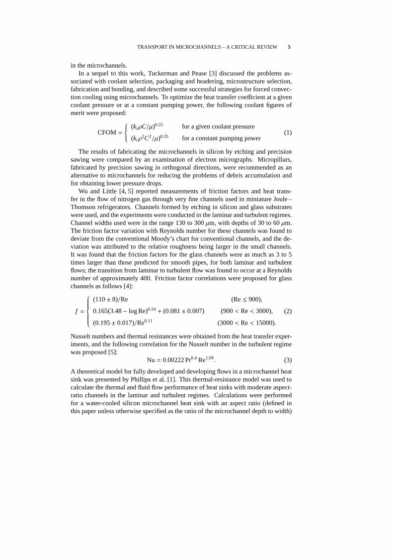
Figure 2 Comparison of theoretical results with experimental data for laminar flow cooling of a siliconchip with water-cooled microchannels [1].
of 4, and the results were found to show very good agreement with experimentaldata [6] for various flow rates in the laminar regime, as shown in Figure 2. Thenumerical results indicated that turbulent flow designs could have equivalent or betterperformance than comparable laminar flow designs.
Mahalingam and Andrews [7] investigated a high-performance air cooling tech-nique for electronic devices and packages that involved high-velocity air flowthrough micro-structured compact heat sinks of large surface area. The heat transfercalculations performed for the air-cooled narrow channels were described in detail.The channels considered were 0.13 to 0.25 mm wide with an aspect ratio of 10, re-sulting in heat transfer surface areas of 47 to 63 cm2 per m3 of heat sink volume.Experiments and predictions showed that these heat sinks were an attractive alterna-tive to conventional forced air circulation heat sinks in terms of improved electricalperformance.
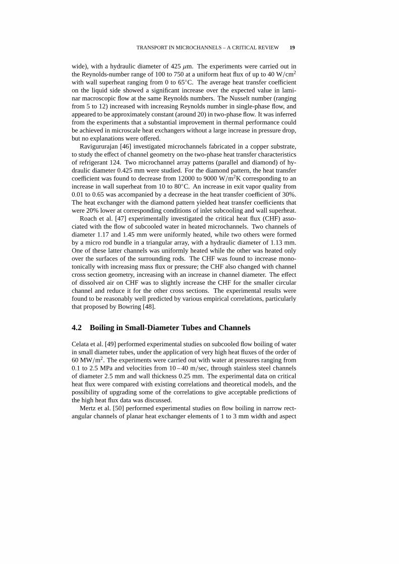
Pfahler et al. [8] experimentally studied the flow of N-propanol through micro-channels of different cross-sectional areas in an effort to identify the channel sizeat which conventional predictions of the friction coefficient no longer hold. It wasfound that for the smaller channel, which was 0.8 µm deep and 100µm wide, theconventional predictions (i. e.,f Re= const) deviated from the experimental resultssignificantly, with friction factor-Reynolds number products being as large as threetimes the predictions. The trend of variation in thef Re product with Reynoldsnumber was also quite different for this channel, as shown in Figure 3. For a deeperchannel (depth of 1.7µm) of the same width, the agreement was better; unfortunatelyno results were presented for the deepest channel (depth of 135µm) considered.Although it was suggested based on these results that a critical channel size existsbelow which the theory for conventional channels fails, the data presented were toosparse (only two channel depths and comparisons of friction factor only for laminar

TRANSPORT IN MICROCHANNELS – A CRITICAL REVIEW 7
Re
0 0.001 0.002 0.003 0.004 0.005 0.006
C=
f*
Re
0
100
200
300
400
500
depth=0.8 micronsdepth=1.7 micronstheory
Figure 3 The product of friction factor and Reynolds number shown as a function of Reynolds number,for 100µm wide channels of two different depths [8].
flow) to support a conclusive hypothesis.Choi et al. [9] measured the inner wall surface roughness, friction factors and con-
vective heat transfer coefficients for flow of nitrogen gas in microtubes with insidediameters ranging from 3 to 81µm. The experimentally determined values of frictionfactor and heat transfer coefficient deviated significantly from those predicted fromcorrelations for conventional-sized tubes. In the laminar regime, the friction factorfollowed f = 53/Re instead of the expected 64/Re dependence. In the turbulentregime, the measured friction factors were lower by 10 to 30% when compared topredictions from conventional correlations. The following correlations for the fric-tion factor were proposed (and may be compared to expressions for conventionaltubes off = 64/Re andf = 0.316 Re−0.25 respectively):
f =
64Re
[1 + 30
(ν
D Ca
)]−1
for laminar flow,
0.140 Re−0.182 for turbulent flow.
(4)
The heat transfer measurements from this study did not agree with the Colburnanalogy for turbulent flow in conventional-size channels. The measured values for(8 jH/ f ) were as high as 7, whereas the Colburn analogy dictates a value of 1 for thisparameter. The Petukhov analogy for turbulent heat transfer, given by (8jH/ f ) =
Pr2/3/[1.07 + 12.7( f /8)1/2(Pr1/2 − 1)], also did not satisfy the experimental data,which were instead correlated as:
Nu =
0.000972 Re1.17 Pr1/3 laminar flow (Re< 2000),
3.82 · 10−6 Re1.96 Pr1/3 turbulent flow (2500< Re< 20000).(5)
The experimental data in the turbulent regime fell above the predictions from the

8 ANNUAL REVIEW OF HEAT TRANSFER, VOL. 13
Dittus – Boelter correlation for conventional tubes.Flow and heat transfer measurements in microchannels etched into silicon in a
series or parallel pattern were obtained by Rahman and Gui [10]. Six heat sinks eachwith microchannels of different aspect ratios were studied with water as the coolant.Measurements were obtained in the inlet and exit regions and included the substrateand coolant temperatures, pressure drop, input power and flow rate. Local and aver-age Nusselt numbers and friction factors were plotted against Reynolds number. Thelocal Nusselt number values were found to be higher than the corresponding valuespredicted from analytical solutions for developing laminar flow. It was concludedthat microchannels provided significant performance and operational advantages interms of higher heat fluxes compared to other cooling methods such as jet impinge-ment and forced convection.
Fabrication processes for microchannel structures were described byHoopman [11]. Various types of microchannel structures and their relative meritsand demerits were discussed, in addition to applications such as electronics cooling,compact heat exchangers, heat shields and fluid distribution systems. A review ofthe literature related to optimum design of microchannel heat sinks was presented byGoodling and Knight [12].
Investigations reported in the past decade on the fundamentals and applications offluid flow and heat transfer through microchannels are discussed in the sections thatfollow.
3 SINGLE-PHASE FLOW
Single-phase flow and heat transfer in microchannels has been studied extensivelythrough experimental and theoretical investigations. Most of this work has been di-rected at quantifying the effects of flow parameters and channel dimensions on theoverall frictional and heat transfer characteristics. In some cases, numerical mod-eling has been used to arrive at configurations and flow parameters which provideoptimum heat transfer rates.
3.1 Experimental Investigations
Water, methanol and Refrigerant-124 have been used as coolants, both as pure fluidsand in the form of binary mixtures. While flow regimes and transition were ad-dressed in some of the studies, others involved a study of the departure of the flowand heat transfer characteristics in microchannels from conventional channel flows.Predictive correlations for heat transfer and friction factors in microchannels havebeen proposed based on these experiments.
Peng et al. [13, 14] experimentally investigated the forced convection of waterthrough single rectangular microchannels with a range of hydraulic diameters (0.133to 0.367 mm) and aspect ratios (0.33 to 1). The microchannels were fabricated in astainless steel substrate. Measurements of the liquid flow rates, liquid temperatures,

TRANSPORT IN MICROCHANNELS – A CRITICAL REVIEW 9
inlet and outlet pressures, wall surface temperatures and heat input to the substratewere obtained under steady-state conditions. Results were plotted as friction factor-Reynolds number graphs, and were found to deviate from the values predicted byclassical correlations. The friction factor was found to be proportional to Re−1.98 un-der laminar conditions and Re−1.72 for turbulent flow, compared to Re−1 and Re−0.25
(Blasius) for conventional channels. The flow was found to be most strongly affectedby the hydraulic diameter and the aspect ratio of the channel. The flow was foundto undergo transition in the Reynolds number range of 200 to 700, with the criticalReynolds number increasing with increasing channel hydraulic diameter as shownin Figure 4. The occurrence of transition was identified from a plot of the frictionfactor versus Reynolds number. The corresponding heat transfer characteristics [14]showed that the Nusselt number was proportional to Re0.62 in the laminar regime,and Re0.8 in the turbulent regime. These results were further analyzed by Peng andPeterson [15], who proposed the following empirical correlations for heat transfer:
Nu = 0.1165
(Dh
Wc
)0.81 ( HW
)−0.79
Re0.62 Pr1/3 for laminar flow, (6)
Nu = 0.072
(Dh
Wc
)1.15
(1− 2.421(Z − 0.5)2)Re0.8 Pr1/3 for fully developedturbulent flow.
(7)
Experiments with water and methanol in microchannels of rectangular cross sectionfabricated into a stainless steel substrate were reported by Wang and Peng [16]. Thechannels were fabricated into test plates of 18 mm width and 125 mm length. Allthe channels had a depth of 0.7 mm, while the channel widths were varied through0.2, 0.4, 0.6 and 0.8 mm; the channel pitch was also varied from 0.24 to 4 mm.
Dh, mm
0.12 0.16 0.2 0.24 0.28 0.32 0.36
Re c
r
200
300
400
500
600
700
Figure 4 Variation of the critical Reynolds number with the hydraulic diameter in a rectangular chan-nel [13]. The critical Reynolds number is found to increase with the hydraulic diameter.

10 ANNUAL REVIEW OF HEAT TRANSFER, VOL. 13
Heat transfer coefficients and Nusselt numbers were plotted against the measuredwall temperatures and Reynolds numbers respectively, for various flow velocities.As would be expected, the heat transfer was greater at lower liquid temperaturesand higher liquid velocities. It was inferred from the Nu-Re variations that fullydeveloped turbulent convection conditions were established in the microchannels atReynolds numbers of 1000 to 1500; transition to turbulence was found to be stronglyinfluenced by liquid temperature, velocity and microchannel size. The turbulent heattransfer coefficients obtained from the experiments (computed from the applied heatflux divided by the difference between the local surface temperature and the inletfluid temperature) were found to be well represented by modifying the constant inthe Dittus – Boelter correlation from 0.023 to 0.00805. Typical results from this workare shown in Figure 5 with methanol as the coolant.
The effects of thermofluid properties and geometrical parameters on convectiveheat transfer in microchannels were further discussed by Peng and Peterson [17].Compared to conventional-size channels, transition was found to be initiated at muchlower Reynolds numbers in the microchannels, with the transition range as well asthe heat transfer characteristics in laminar and turbulent flow, being influenced notonly by the Reynolds number but also by the liquid temperature, velocity and mi-crochannel size.
Peng and Wang [18] studied both single-phase convection and boiling character-istics of subcooled water in rectangular microchannels of cross section 0.6×0.7 mm,machined into stainless steel. In single phase convection, a steep increase of the wallheat flux was observed when plotted against the wall temperature, beyond whichthe heat flux for the microchannel was higher than for a conventional (9 mm diam-eter) tube. The results also indicated that the laminar or transition convection heat
Re
100 200 1000 2000
Nu
0.5
1
2
3
45
10
test section No.3test section No.4test section No.5test section No.6
METHANOL
Eq.(10)
Figure 5 Variation of the average Nusselt number with Reynolds number, for single phase forced con-vection flow of methanol in a rectangular microchannel [16]. The reduction in Nusselt number with anincrease in the Reynolds number may be noticed in the low Reynolds number regime.

TRANSPORT IN MICROCHANNELS – A CRITICAL REVIEW 11
transfer rates in microchannels could reach or exceed those in the turbulent regimein conventional tubes. The nucleate boiling heat flux was found to be intensified inmicrochannels, and the wall superheat required for flow boiling was much smallercompared to conventional channels for an identical wall heat flux. Moreover, thetransition between single phase convection and nucleate boiling was observed to becharacterized by an absence of partial nucleate boiling.
Single phase forced convection with binary mixtures of water and methanol inmicrochannels (hydraulic diameter of 0.133 to 0.367 mm) was investigated experi-mentally by Peng and Peterson [19]. The laminar regime extended up to Reynoldsnumbers of 70 to 400 depending on the flow conditions, and fully developed turbu-lent heat transfer was achieved in the Reynolds number range of 200 to 700. Thetransition Reynolds number decreased as the microchannel hydraulic diameter wasreduced. The channel hydraulic diameter and aspect ratio were discussed as distinctsignificant variables. The results indicated that the influence of the aspect ratio onheat transfer was further affected by the concentration of the mixture, and varied as afunction of the mole fraction of the mixture. As shown in Figure 6, the heat transfercoefficient was greater for the smaller mole fractions of the more volatile component,reaching a maximum at a characteristic mole fraction; the heat transfer enhancementalso occurred over a larger mole fraction range as the mass flow rate was increased.
Harms et al. [20] studied the heat transfer and pressure drop characteristics of“deep” rectangular microchannels, which had a width of 251µm and a depth of1030µm, at deionized water flow rates of 5.47 to 118 cm3/s. A critical Reynoldsnumber of 1500 was identified for the onset of turbulence. This lower value, relativeto conventional channels, was attributed to the inlet manifold conditions and chan-nel roughness. The experimental results were found to be in good agreement with
x
0 0.2 0.4 0.6 0.8 1
Hea
ttra
nsfe
rco
effi
cien
t,W
/(m
2 K)
1000
2000
3000
4000
5000
6000mass flux 190 kg/(m2s)mass flux 782 kg/(m2s)
Figure 6 The effect of the concentration of the more volatile component, and the mass flux of a binarymixture of water and methanol, on the heat transfer coefficient, in single phase forced convection flowthrough a rectangular microchannel [19].

12 ANNUAL REVIEW OF HEAT TRANSFER, VOL. 13
those from a one-dimensional thermal resistance model, indicating that classical heattransfer analyses were applicable to the geometry investigated. The volumetric flowrate, pressure drop and pumping power were found to be inversely related to the ther-mal resistance; for a given pressure drop and pumping power, the thermal resistancewas found to be smaller for deeper channels.
Based on a dimensional analysis of the variables influencing laminar forced con-vection, Tso and Mahulikar [21] proposed that the Brinkman number be used as theparameter for correlating convective heat transfer in microchannels. Previous re-searchers had observed that the Nusselt number could decrease with an increase inReynolds number in the laminar regime, and remain unaffected by Reynolds num-ber in the transition regime [15–17]; Tso and Mahulikar offered possible reasons forsuch behavior and proposed a dimensionless geometric parameter for the analysis ofmicrochannels. It was proposed that the increase or decrease in the Nusselt numberas the Reynolds number increases in the laminar regime depends on whether the in-crease in Reynolds number is brought about by an increase in velocity or a reductionin fluid viscosity due to heating. An increase in Reynolds number caused by an in-crease in velocity would increase the Nusselt number; however, when this increasein Reynolds number is due to a reduction in viscosity, it is claimed that the Nusseltnumber would decrease. This work for laminar flow was extended by Tso and Mahu-likar [22] to cover flow transition in microchannels. Experimental results were alsopresented in [23] and found to correlate well in terms of the Brinkman number forlaminar flow.
Adams et al. [24] investigated turbulent forced convection of distilled water in mi-crochannels of 0.76 and 1.09 mm diameter fabricated in a copper substrate by elec-trode discharge machining. The Nusselt numbers obtained were found to be higherthan those predicted by traditional large-channel correlations. The experimental datawere compared with predictions from correlations for small-diameter channels [25];the divergence in the comparison increased with an increase in Reynolds number,with the experimental data being higher than the predictions. Figure 7 shows aplot of an enhancement ratio (experimental to predicted values) as a function of theReynolds number for three channel diameters. The enhancement factor was seen toincrease as the channel diameter decreased, and as the Reynolds number increased.A correlation for the Nusselt number in turbulent forced convection was proposed forcircular microchannels of diameters 0.102 to 1.09 mm (data for smaller tubes fromthe literature were included in their database to extend the diameter range), Reynoldsnumbers from 2600 to 23000 and Prandtl numbers of 1.53 to 6.43. The correlationproposed, which gathered the data to within±18.6%, was
Nu = NuGn(1 + F), (8)
in which NuGn is calculated from the correlation proposed by Gnielinski [25],
NuGn =( f /8) (Re− 1000) Pr
1 + 12.7( f /8)1/2(Pr2/3 − 1).

TRANSPORT IN MICROCHANNELS – A CRITICAL REVIEW 13
Re
0 5000 10000 15000 20000 25000
Enh
acem
ent
rati
o
0.5
1.0
1.5
2.0
2.5
3.0
D=0.102 mmD=0.760 mmD=0.190 mm
Figure 7 Variation of the “enhancement ratio” for the experimental Nusselt number over the Gnielinskicorrelation with Reynolds number [24].
The friction factor correlation to be used with this expression [26] is given by
f =[1.82 log(Re) − 1.64
]−2 . (9)
Adams et al. [27] extended the experiments to a non-circular microchannel of hy-draulic diameter 1.13 mm. The experimental Nusselt numbers for this case werefound to be well predicted by the Gnielinski correlation; based on this comparison, ahydraulic diameter of approximately 1.2 mm was suggested as a lower limit for theapplicability of standard turbulent convection correlations.
A somewhat unusual experimental configuration in the literature on microchan-nels was considered by Zhuang et al. [28], who obtained the heat transfer charac-teristics under the impingement of transformer oil and FC-72 on two-dimensionalmicrochannels. Local heat transfer coefficients were obtained in stagnation and par-allel flows for a range of Reynolds number from 70 to 170 for oil and 911 to 4807for FC-72. The influence of the liquid velocity, channel size and the Prandtl numberon the heat transfer behavior were studied. An empirical correlation was developedby analyzing the data for the two liquids used:
Nux = 0.429 Re0.583 Pr1/3( x2H
)0.349 ( B2H
)−0.494
. (10)
Yu et al. [29] reported experimental investigations on an air-cooled microchannelheat sink. The microchannels considered were of large aspect ratio (62.5) with theexpectation that the pressure drop would be lower. The experimentally determinedtotal thermal resistance was found to be in good agreement with that determinedfrom a thermal resistance model, with the assumption of a Nusselt number of 6.5in the model. The pressure drop was found to have a large discrepancy, up to 18%,

14 ANNUAL REVIEW OF HEAT TRANSFER, VOL. 13
from the predicted values, especially at high air flow rates; this was attributed to theentrance and exit losses in the heat sink which were ignored in the pressure dropcalculations. The cooling capacity of the heat sink was approximately 1700 W witha heat flux of approximately 15 W/cm2. With a volumetric flow rate of 140 m3/hr,the pressure drop encountered was found to be as low as 400 Pa.
In summary, experimental investigations on single-phase flow in microchannelshave focussed mainly on three aspects. The effect of the channel dimensions andgeometry on flow and heat transfer was one of the primary concerns. An understand-ing of flow transitions has been sought and critical Reynolds numbers have beenproposed for transition in microchannel flows. A third area of research has led tocorrelations being proposed based on experimental measurements for various flowregimes, in terms of fluid properties and microchannel geometry.
3.2 Models and Optimization Studies
A number of numerical and analytical solutions have been reported for single-phaseconvective flow and heat transfer in microchannels. Optimization of the dimensionsand geometry of microchannels has also been attempted based on theoretical models.
A theoretical model for heat transfer and fluid flow in the microchannels formedbetween two parallel plates, incorporating the effects of the electric double layer(EDL) at the interface between the solid surface and liquid was presented by Malaet al. [30]. The effects of the EDL field and the channel size on the flow and heattransfer were studied. The EDL field was obtained by a linear approximate solutionof the Poisson – Boltzmann equation. In order to accommodate for the retardation ofthe fluid due to the EDL field, an apparent viscosity was introduced to modify thegoverning energy equation, and numerical solutions were obtained. Comparisonswere also presented, with very good agreement, of the predicted volume flow ratesfrom the mathematical model considering EDL effects with results from experimen-tal investigations on the flow of aqueous solutions of potassium chloride throughmicrochannels [31].
In further work by Yang et al. [32], the EDL field in rectangular microchan-nels was determined by solving the non-linear two-dimensional Poisson – Boltzmannequation. The effects of the flow-induced electrokinetic field were also consideredin the equation of motion. The flow and heat transfer characteristics in steady, fullydeveloped laminar flow with and without the electrokinetic effects included werecompared. For aqueous solutions of low ionic concentration and a solid surface ofhigh electrical potential, the liquid flow and heat transfer in the microchannels weresignificantly influenced by the presence of the electric field and the induced elec-trokinetic flow, as shown in Figures 8 and 9.
A forced convection cooling scheme with microchannels formed between platefins was investigated by Kleiner et al. [33]. A thermal resistance model was devel-oped incorporating the pressure drop and pumping power, using which optimizationstudies were performed. Experiments were conducted on heat sinks fabricated from

TRANSPORT IN MICROCHANNELS – A CRITICAL REVIEW 15
Non-dimensional pressure difference
0 500 1000 1500 2000Non
-dim
ensi
onal
volu
met
ric
flow
rate
0
1
2
3
4
51 no EDL effects2 c=150 mV, c0=10-6 M3 c=200 mV, c0=10-8 M
12
3
Figure 8 Variation of the non-dimensional flow rate with the non-dimensional pressure difference fordifferent concentrations and zeta (electrical) potentials, calculated from a computational model for mi-crochannel flow considering the electric double layer effect [32].
Non-dimensional channel length
10-2 10-1 100
Loc
alN
usse
ltnu
mbe
r
2
3
4
5
1 no EDL effects
2 with EDL effects
c=200 mV, c0=10-8 M
1
2
Figure 9 Comparison of the local Nusselt number variation along the channel length, from computationalsolutions with and without electric double layer effect incorporated in the formulation [32].
copper and aluminum foils, with channel widths of 200 and 500µm. Thermal resis-tance values (defined based on the maximum temperature rise of the heat exchangersurface above the coolant inlet temperature) as low as 0.2 K/W were measured, andfound to agree with model predictions to within 15 to 27%. The measured thermalresistance of the microchannel heat sink was lower than direct air cooled heat sinksby a factor of more than 3.
Takamatsu et al. [34] performed a numerical study of the flow of superfluid he-

16 ANNUAL REVIEW OF HEAT TRANSFER, VOL. 13
lium in capillary channels of small diameters. Two sets of channels with large(8.1 – 96µm) and small (0.76 – 4.7 µm) diameter ranges were analyzed represent-ing a “superleak” (a porous element with microchannels in a fountain effect pumpused under reduced gravity in space applications). The dynamics of superfluid flowwere incorporated in the governing equations through a “two-fluid model” in whichsuperfluid helium is represented through two components: a superfluid componentwith no entropy and viscosity, and a normal fluid component possessing all the en-tropy and viscosity. It was assumed that the two fluid components can flow througheach other without friction. Comparisons were presented for the predicted veloc-ity fields calculated with the assumption of only the normal fluid component beingpresent, to those from the two-fluid model. The results of the study indicated theexistence of an optimum channel diameter for maximizing the mass flow rate.
Bau [35] conducted an investigation to optimize the axial variation of the cross-sectional area of rectangular microchannels in a flat-plate micro heat exchanger, tominimize thermal resistance. An optimization problem was formulated under theassumption of fully developed incompressible flow and solved to achieve minimaltemperature gradients.
The relative performance of jet impingement and microchannel cooling was com-pared by Lee and Vafai [36] for high heat flux applications. Flow and heat transfercharacteristics of multiple-jet impingement were discussed, with reference to the ef-fect of the spent flow on the optimal cooling configuration. Friction and heat transferin microchannel cooling were also discussed, and a procedure for optimizing thechannel geometry was introduced. Based on a comparison of the maximum attain-able heat flux, microchannel cooling was found to be preferable for targets smallerthan 7× 7 cm, while impingement cooling, with proper treatment of the spent flow,was comparable to, or better than, microchannel cooling for larger target dimensions.
Theoretical models developed for the analysis of microchannel flows are seen togenerally fall into two categories – models which incorporate a detailed accountingof the governing equations for flow and heat transfer, and thermal resistance modelswhich deal with overall temperature drops. Fluid flow models have been augmentedfor special flow situations, and considerations such as the effect of an electric doublelayer have been included. One of the objectives common to many of the modelingstudies has been to optimize channel geometry in order to minimize thermal resis-tance.
4 BOILING AND TWO-PHASE FLOW
Boiling and two-phase flow in microchannels has been studied in a number of in-vestigations in the literature. Both mini and microchannels fabricated as part of heatsinks as well as small-diameter tubes and channels have been considered. Two-phaseflow of air-water mixtures in microchannels has been investigated, including a com-parison of the heat transfer performance in single-phase and two-phase flows. Flowpatterns in microchannels and small diameter tubes have also observed.

TRANSPORT IN MICROCHANNELS – A CRITICAL REVIEW 17
4.1 Boiling in Mini and Microchannels
Two-phase flow in the cooling of electronic equipment using mini and microchan-nel heat sinks was investigated by Bowers and Mudawar [37–39]. Circular channelsof diameter 2.54 and 0.51 mm (arbitrarily classified as mini and microchannels, re-spectively) were studied, with R113 used as the coolant. Critical heat flux valuesof the order of 200 W/cm2 were experimentally obtained for a range of inlet sub-cooling from 10 to 32◦C, for flow rates less than 95 ml/min. A heat sink thickness-to-channel diameter ratio of 1.2 was found to provide a good compromise betweenminimizing the overall thermal resistance and obtaining structural integrity; a valuefor this ratio of less than 2 provided negligible surface temperature gradients even atheat fluxes of 200 W/cm2 [37]. A pressure drop model was also developed to aid indetermining the channel diameter for a specific cooling application [38]. This modelaccounted for the pressure drop in the single-phase inlet region, the single and two-phase heated region and the two-phase unheated outlet region. The homogeneousequilibrium two-phase flow model was found to predict the heat sink pressure dropwith good accuracy.
A comparison of the theoretical predictions of pressure drop with experimentaldata was presented in Bowers and Mudawar [39], as shown in Figure 10. The majorcontributor to the pressure drop in both mini and micro channels was the accelerationresulting from evaporation; the compressibility effect was also important for the mi-crochannel in high flux applications when the Mach number exceeded 0.22. Channelerosion due to flow boiling in the mini channel geometry was found to be at accept-able levels but the erosion effects in the microchannel at high heat fluxes exceeded“allowable limits”. A single correlation for the critical heat flux was developed from
Ppred , bar
10-3 10-2 10-1
P exp
,ba
r
10-3
10-2
10-1
Plot includes 73 data pointswith +/- 30% error band
All data pointsfor xl <1
Heat sink L / D Ltot / D
mini 3.94 11.3micro 19.6 56.0
Figure 10 Comparison of theoretical predictions of pressure drop in mini and microchannels with exper-imental data [39].

18 ANNUAL REVIEW OF HEAT TRANSFER, VOL. 13
experimental results for both the channels [39]:
qm,p
G hf g= 0.16 We−0.19
( LD
)0.54
. (11)
The influence of liquid velocity, subcooling, property variations and microchannelconfiguration (width, pitch and number of channels) on the heat transfer behavior,cooling performance and heat transfer and liquid flow mode transition (point beyondwhich the heat transfer coefficient is nearly independent of the wall temperature)in flow boiling in rectangular microchannels was studied by Peng et al. [40]. Ex-periments on nucleate flow boiling indicated that the liquid velocity and subcoolingdid not affect fully developed nucleate boiling, but greater subcooling increased thevelocity and suppressed the initiation of flow boiling.
Peng et al. [41] extended this work to experiments on the flow boiling of bi-nary water/methanol mixtures in microchannels. Eight rectangular microchannelconfigurations, each of length 50 mm with hydraulic diameter varying from 0.15 to0.267 mm, were tested at nine different mixture mole fractions. The liquid subcool-ing ranged from 38 to 82◦C, and the liquid velocity was varied from 0.1 to 4.0 m/sec.The results were presented as boiling curves (heat flux versus wall superheat) andheat transfer coefficients. The heat transfer coefficient at the onset of flow boilingand in the partial nucleate boiling region was greatly influenced by liquid concentra-tion, microchannel and plate configuration, flow velocity and subcooling. However,these parameters had little effect in the fully nucleate boiling regime. In general,mixtures with small concentrations of methanol augmented heat transfer relative tothat obtained with pure methanol whereas for large methanol concentrations, the heattransfer was lower.
A further extension of this study of flow boiling to V-shaped microchannels wasreported by Peng et al. [42]. Microchannel hydraulic diameters of 0.2 to 0.6 mm atgroove angles from 30 to 60 deg. were tested experimentally, and an optimum valuefor both these parameters was found to exist which resulted in a maximum in flowboiling heat transfer. In contrast to conventional channels, no bubbles were observedto form in the V-shaped microchannels during flow boiling even with heat fluxes ashigh as 106 W/m2.
Ha and Peterson [43] performed an analytical investigation of the heat transferin evaporating thin liquid films in V-shaped micro grooves with non-uniform inputheat flux. Liquid conduction and interfacial vaporization were both considered indetermining the local interfacial mass flux, and hence in defining a local heat trans-fer coefficient. An expression was developed for the evaporating film profile (axialvariation of film thickness). The axial flow of the evaporating film was further in-vestigated by Ha and Peterson [44], taking into account a gravity term to incorporatethe effect of small tilt angles. The resulting nonlinear equation was solved using aperturbation method.
Both single and two-phase flow of refrigerant 124 in a microchannel heat ex-changer were experimentally investigated by Cuta et al. [45]. The heat exchangerconsisted of 54 microchannels of rectangular cross section (1 mm deep by 0.27 mm
TRANSPORT IN MICROCHANNELS – A CRITICAL REVIEW 19
wide), with a hydraulic diameter of 425µm. The experiments were carried out inthe Reynolds-number range of 100 to 750 at a uniform heat flux of up to 40 W/cm2
with wall superheat ranging from 0 to 65◦C. The average heat transfer coefficienton the liquid side showed a significant increase over the expected value in lami-nar macroscopic flow at the same Reynolds numbers. The Nusselt number (rangingfrom 5 to 12) increased with increasing Reynolds number in single-phase flow, andappeared to be approximately constant (around 20) in two-phase flow. It was inferredfrom the experiments that a substantial improvement in thermal performance couldbe achieved in microscale heat exchangers without a large increase in pressure drop,but no explanations were offered.
Ravigururajan [46] investigated microchannels fabricated in a copper substrate,to study the effect of channel geometry on the two-phase heat transfer characteristicsof refrigerant 124. Two microchannel array patterns (parallel and diamond) of hy-draulic diameter 0.425 mm were studied. For the diamond pattern, the heat transfercoefficient was found to decrease from 12000 to 9000 W/m2K corresponding to anincrease in wall superheat from 10 to 80◦C. An increase in exit vapor quality from0.01 to 0.65 was accompanied by a decrease in the heat transfer coefficient of 30%.The heat exchanger with the diamond pattern yielded heat transfer coefficients thatwere 20% lower at corresponding conditions of inlet subcooling and wall superheat.
Roach et al. [47] experimentally investigated the critical heat flux (CHF) asso-ciated with the flow of subcooled water in heated microchannels. Two channels ofdiameter 1.17 and 1.45 mm were uniformly heated, while two others were formedby a micro rod bundle in a triangular array, with a hydraulic diameter of 1.13 mm.One of these latter channels was uniformly heated while the other was heated onlyover the surfaces of the surrounding rods. The CHF was found to increase mono-tonically with increasing mass flux or pressure; the CHF also changed with channelcross section geometry, increasing with an increase in channel diameter. The effectof dissolved air on CHF was to slightly increase the CHF for the smaller circularchannel and reduce it for the other cross sections. The experimental results werefound to be reasonably well predicted by various empirical correlations, particularlythat proposed by Bowring [48].
4.2 Boiling in Small-Diameter Tubes and Channels
Celata et al. [49] performed experimental studies on subcooled flow boiling of waterin small diameter tubes, under the application of very high heat fluxes of the order of60 MW/m2. The experiments were carried out with water at pressures ranging from0.1 to 2.5 MPa and velocities from 10 – 40 m/sec, through stainless steel channelsof diameter 2.5 mm and wall thickness 0.25 mm. The experimental data on criticalheat flux were compared with existing correlations and theoretical models, and thepossibility of upgrading some of the correlations to give acceptable predictions ofthe high heat flux data was discussed.
Mertz et al. [50] performed experimental studies on flow boiling in narrow rect-angular channels of planar heat exchanger elements of 1 to 3 mm width and aspect

20 ANNUAL REVIEW OF HEAT TRANSFER, VOL. 13
ratios of up to 3, fabricated in copper. Saturated flow boiling in a vertical orienta-tion was studied, with water and R-141b as the working fluids. Boiling curves andthe variations of the heat transfer coefficient with local and average heat fluxes wereobtained.
Sturgis and Mudawar [51, 52] studied flow boiling of FC-72 in long rectangularmini-channels of cross section 5.0×2.5 mm, to explore the conditions leading to crit-ical heat flux. Flow visualization studies revealed that at the CHF, vapor coalescedinto a series of patches resembling a wavy vapor layer which propagated along theheated wall, and allowed the liquid to contact the wall only at discrete locations. Thelength and height of the vapor patch was found to increase along the flow direction,but decreased with increasing subcooling and velocity [51]. A model to predict criti-cal heat flux was also presented [52], incorporating the observed periodic distributionof increasingly larger vapor patches along the surface, by idealizing the effect as asinusoidal interface with amplitude and wavelength increasing in the flow direction.The critical interfacial wavelength was predicted through a stability analysis, whichutilized the velocities and average thickness obtained from a separate flow model.The model predicted the near-saturated CHF data in long channels within a meanabsolute error of 10%.
4.3 Two-Phase Flow
Flow visualization studies on two-phase flow of air-water mixtures in tubes withsmall hydraulic diameters were performed by Coleman and Garimella [53]. Tubes ofcircular and rectangular cross section were studied. Flow patterns were observed andflow regime maps obtained for superficial velocities in the range of 0.1 to 100 m/secfor the gas and 0.01 to 10 m/sec for the liquid. The effects of tube diameter andshape on the flow patterns for a range of hydraulic diameters from 1.3 to 5.5 mmwere presented. Flow transition observed in the experiments was contrasted to thatpredicted by correlations for flow in large tubes. It was concluded that the tubediameter influences the superficial gas and liquid velocities at which flow transitionstake place, due to combined effects of surface tension and the tube hydraulic diameterand aspect ratio.
An experimental study on two-phase air-water flow in circular and triangular mi-crochannels of hydraulic diameters 1.1 and 1.45 mm was conducted by Triplett etal. [54, 55]. Flow pattern maps were obtained based on visual observation, andconsisted of bubbly, churn, slug, slug-annular and annular flows. The data werecompared with flow regime transition models and correlations but with poor agree-ment [54]. Void fractions were estimated by analyzing photographs and were com-pared with predictions which assumed a homogeneous model and used various corre-lations. Frictional pressure drops in the microchannel were measured and comparedwith two-phase friction models. The void fraction and channel pressure drop werefound to be best predicted by the homogeneous mixture assumption. The modelsand correlations over-predicted the channel void fraction and pressure drop in annu-lar flow, suggesting that in this regime the liquid-gas interfacial momentum transfer

TRANSPORT IN MICROCHANNELS – A CRITICAL REVIEW 21
and wall friction in microchannels may be significantly different from those in largerchannels [55].
Ma et al. [56] presented a mathematical model for the liquid pressure drop inliquid-vapor flow in triangular microgrooves. They used a fluid flow model whichconsidered the interfacial shear stresses due to liquid-vapor frictional interaction,with a combination of analytical and finite-difference methods. Results were re-ported for channel angles ranging from 20 to 60 deg, and contact angles (angle be-tween the liquid-vapor meniscus and the groove wall) from 0 to 60 deg. A dimen-sionless vapor-liquid interface flow number was introduced to incorporate interfacialshear stress into the formulation, and calculations were performed with this numberas a parameter. Preditions for the product of the friction factor and Reynolds numberwere found to be strongly dependent upon the channel angle, the contact angle andthe dimensionless interface flow number. A comparison of these predictions with ex-perimental data [57,58] was found to be satisfactory. The dependence of the frictionfactor-Reynolds number product on the contact angle and the groove angle from thisstudy is shown in Figure 11.
Most of the work reported in the literature on boiling and heat transfer in mi-crochannels has been related to the cooling of electronic equipment. Attention wasfocussed on determining (and minimizing) the overall thermal resistance, as well ason obtaining and correlating critical heat flux data. Friction models have been devel-oped to describe the frictional effects in two-phase liquid-vapor flow. Visualizationof flow regimes and comparisons between single-phase and two-phase cooling meth-ods have also been presented.
Contact angle, degrees
0 10 20 30 40 50 60
f*
Re
9
10
11
12
13
14
152 =60o
2 =40o
2 =20o
by this paper
Ayyaswamy et al.
Figure 11Variation of the friction factor – Reynolds number product with the interfacial contact angle forflow in a triangular microgroove [56].
22 ANNUAL REVIEW OF HEAT TRANSFER, VOL. 13
5 GAS FLOW
Experimental studies as well as theoretical models incorporating slip flow bound-ary conditions and compressibility effects of gas flow through microchannels andmicrotubes have been reported. Theoretical results obtained with and without the as-sumption of slip boundary conditions have been compared, and the effects of channeldimensions and operational parameters on friction and heat transfer have been exper-imentally investigated.
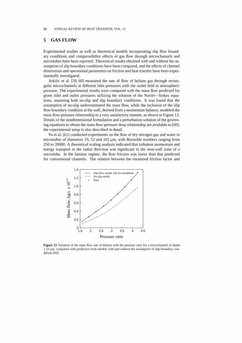
Arkilic et al. [59, 60] measured the rate of flow of helium gas through rectan-gular microchannels at different inlet pressures with the outlet held at atmosphericpressure. The experimental results were compared with the mass flow predicted forgiven inlet and outlet pressures utilizing the solution of the Navier – Stokes equa-tions, assuming both no-slip and slip boundary conditions. It was found that theassumption of no-slip underestimated the mass flow, while the inclusion of the slipflow boundary condition at the wall, derived from a momentum balance, modeled themass flow-pressure relationship in a very satisfactory manner, as shown in Figure 12.Details of the nondimensional formulation and a perturbation solution of the govern-ing equations to obtain the mass flow-pressure drop relationship are available in [60];the experimental setup is also described in detail.
Yu et al. [61] conducted experiments on the flow of dry nitrogen gas and water inmicrotubes of diameters 19, 52 and 102µm, with Reynolds numbers ranging from250 to 20000. A theoretical scaling analysis indicated that turbulent momentum andenergy transport in the radial direction was significant in the near-wall zone of amicrotube. In the laminar regime, the flow friction was lower than that predictedfor conventional channels. The relation between the measured friction factor and
Pressure ratio
1.5 2 2.5 3 3.5 4 4.5
Mas
sfl
ow,k
g/s
x10
-11
0
0.2
0.4
0.6
0.8
1.0
1.2
1.4Slip-flow model, full accomodationNo-slip modelData
Figure 12 Variation of the mass flow rate of helium with the pressure ratio for a microchannel of depth1.33 µm, compared with prediction from models with and without the assumption of slip boundary con-ditions [60].

TRANSPORT IN MICROCHANNELS – A CRITICAL REVIEW 23
Reynolds number was found to be linear, and was correlated based on the experi-ments as:
f = 50.13/Re (Re< 2000). (12)
The friction factor was lower than predictions for conventional tubes in the turbulentregime as well, and was correlated as
f = 0.302/Re0.25 (6000< Re< 20000). (13)
In the turbulent regime, heat transfer was enhanced and the Nusselt number wasmuch higher than that predicted by conventional correlations for large tubes. Therecommended correlation was:
Nu = 0.007 Re1.2Pr0.2 (6000< Re< 20000). (14)
Flows in two dimensional microchannels were investigated using a direct simulationMonte Carlo technique by Mavriplis et al. [62]. Supersonic, subsonic and pressure-driven low speed flows were simulated in microchannels of different aspect ratiosfor a range of continuum to transitional-regime rarefied flows. The channel surfaceheat flux was found to depend on the Knudsen number and channel length. As theKnudsen number increased, the heat flux decreased monotonically along the channelwall, and the flow became fully subsonic in the channel. These effects were ex-plained in light of the shock-boundary interaction and the broadening of the shockwith increases in Knudsen number and channel length.
Kavehpour and Faghri [63] analyzed gas flow in microchannels assuming a slip-flow regime, in order to study the effect of gas compressibility and rarefaction on flowand heat transfer. Compressible forms of the momentum and energy equations weresolved using finite differences with a slip velocity and temperature jump boundaryconditions expressed in terms of the Knudsen number. The mass flow rates, frictioncoefficients and the axial pressure distribution were compared with experimental re-sults [59, 64] for nitrogen and helium, and found to be in very good agreement.The Nusselt number and friction coefficient were substantially reduced for slip flowscompared to continuum flows. It was also shown that the effect of compressibilitywas important at high Reynolds numbers, and that the effect of rarefaction was sig-nificant for lower Reynolds numbers in supersonic flow, leading to a reduced wallheat flux.
Guo and Wu [65] investigated gas flow in a smooth microtube, to examine theeffect of compressibility on the friction coefficient and Nusselt number. The two-dimensional axial and radial momentum equations and the energy equation weresolved along with the equation of state for an ideal gas written in terms of the in-let Mach number, using a finite difference forward marching technique. The varia-tions of pressure, density and temperature, the local friction coefficients and the localNusselt number were calculated from the analysis, with the inlet Mach number as aparameter. The local Nusselt number was found to increase with the dimensionlesslength due to compressibility effects. It was found that the product of the frictionfactor and Reynolds number was not a constant, but depended instead on the value

24 ANNUAL REVIEW OF HEAT TRANSFER, VOL. 13
of the Reynolds number. This was attributed to the variation of the velocity profilealong the tube as a result of compressibility and the consequent absence of fullydeveloped flow.
Chen et al. [66] studied the flow of nitrogen and helium gas in microchannels withlarge (width to height) aspect ratios, for which a two-dimensional flow was assumed.Compressibility effects and a slip boundary condition were included in the numericalcomputations. The numerical results agreed with experimental data [59] to within1.15% for pressure and 3.13% for mass flow rate. Gas flow in microchannels wasfound to be characterized by small velocities but high pressure gradients due to thelarge wall shear stresses.
An analysis of slip flow in long microgrooves was presented by Niu [67], usingwhich flow in two-dimensional microchannels and three-dimensional straight andspiral grooves (in turbomolecular pumps) was studied numerically. The non-linearpressure gradient obtained along the microchannels was attributed to variations indensity.
The major geometric parameters that have been investigated in the analysis ofgas flow through microchannels are the diameters of microtubes and aspect ratiosof channels. Slip boundary conditions and compressibility effects have been in-corporated into models. Experimental studies on gas flow in microchannels haveconsidered flow rates, Reynolds numbers, pressure ratios and channel dimensions asparameters.
6 DESIGN AND TESTING FOR ELECTRONICS COOLING
Some of the investigations into microchannels in the literature have specifically dealtwith optimal design of heat sinks for specific electronics cooling applications. Per-formance characterization and testing of electronic devices with microchanneled heatsinks has also been reported.
Weisberg et al. [68] reported an analysis aimed at developing an optimal designalgorithm for heat exchangers with integrally fabricated microchannels for coolingelectronic chips. Numerical analysis of the two-dimensional conjugate heat transferproblem in the solid substrate and fluid was presented. A design algorithm for theselection of heat exchanger dimensions was developed, resulting in an expressionfor the minimum pumping power specified as a function of the channel geometry, asfollows:
PT =
L µ
8ρ2f C
2pWT H3
c
wwc
(1 + A)2C(A)(R∗ − R)2
, (15)
whereC(A) is a constant which depends on the channel geometry. The values ofRforuse in the above expression were presented in dimensionless form (r = WTkf LR/Hc)as in Figure 13, as a function of channel geometry.
Design and testing of microchannel heat exchangers for cooling semiconduc-tor laser diode arrays capable of dissipating very high heat fluxes of the order of

TRANSPORT IN MICROCHANNELS – A CRITICAL REVIEW 25
h
1 1.5 2 2.5 3 3.5
r
0.01
0.02
0.1
A=3 (0.3) A=3 (0.5) A=3 (0.7)
A=6 (0.3) A=6 (0.5) A=6 (0.7)
A=9 (0.3) A=9 (0.5) A=9 (0.7)
Figure 13 Dimensionless thermal resistance of a microchannel heat sink as a function of channel heightand aspect ratio [68].
1000 W/cm2 was reported by Roy and Avanic [69]. These heat exchangers con-sisted of microchannels of almost rectangular cross section, with dimensions of0.5 × 12 mm. The overall thermal resistance of the heat exchangers was less than0.03 W/◦C, which was stated to be an improvement of 2 to 3 times over other state-of-the-art heat sinks. Another design with dimensions of 0.125× 12 mm was alsotested and found capable of dissipating 200-300 W from a solder-bonded resistor ofarea 0.5 mm2, while limiting the surface temperature rise to 20 – 30◦C.
Aranyosi et al. [70] reported a parametric analysis and experiments on compactheat sinks for power packages, which utilized air impingement cooling in microchan-nels. A thermal resistance model was developed and used to determine the influenceof the operational (static pressure and pumping power) and geometric parameterson thermal resistance. Measured thermal resistances and pressure drops agreed withmodel predictions to within 20%. Heat dissipation rates as high as 10 W/cm2 weremeasured.
Gillot et al. [71] presented a three-dimensional analysis of a high-performancemicro heat sink for a power multichip module. Thermal resistance values obtainedfrom the simulation were compared with experimental results, and the agreementwas found to be within 10%. Comparing one-dimensional and three-dimensionalapproaches of analysis, a parameter s was defined to represent the “heat spread ef-fect” ass = (Rth 1D−Rth 3D)/Rth 1D. The heat spread effect was found to decrease withan increase in the heat transfer coefficient.
Perret et al. [72] investigated the use of water-cooled microchannel heat sinks in-tegrated into a silicon substrate. Using a finite-element analysis the optimum value

26 ANNUAL REVIEW OF HEAT TRANSFER, VOL. 13
of the total thermal resistance was obtained. Thermal resistances were calculated forhexagonal, diamond-shaped and rectangular channel geometries, and the rectangulargeometry was shown to cause the lowest thermal resistance. Experiments on singleand two-phase micro heat exchangers for cooling insulated gate bipolar transistors(IGBT) were performed by Gillot et al. [73]. The heat exchangers were fabricatedby brazing the copper microchannel heat sinks on to silicon chips. Water and FC-72were used as the cooling fluids. As expected, the two-phase heat exchanger resultedin lower thermal resistances compared to single-phase operation. Further, the re-quired flow rates and pressure drops were also lower for the two-phase exchangerfor the same dissipated power. The experimental measurements agreed with predic-tions of the thermal resistance to within 13%.
7 MEASUREMENT TECHNIQUES
A bulk of the experimental work on microchannel flows has utilized conventionalmeasurement techniques such as thermocouples for local temperatures, and the mea-surement of overall flow rates and pressure drops. More recently, new techniques arebeing utilized for obtaining localized measurements, helped in large part by advancesin microfabrication technologies.
Optical flow measurements using microscopic observation in different microchan-nel geometries, with flow rates in the range 0.01 – 1000µl/min, were reported byRichter et al. [74]. The application of concern was liquid dosing, involving verysmall discharge and precise flow control, for which the microchannels were fabri-cated as etched V grooves in silicon, covered with pyrex glass by anodic bonding.The maximum channel width ranged from 28 to 182µm. The measured flow rateswere found to be in good agreement with theoretical values for laminar flow througha straight channel with a triangular cross section.
Meinhart et al. [75] described the use of Particle Image Velocimetry for the mea-surement of local velocities in microchannel flow. The accuracy of the measurementtechnique was demonstrated by measuring known flow fields in a 30× 300µm mi-crochannel. The results agreed well with analytical solutions for Newtonian flow inrectangular channels.
Measurement of the local flow and temperature fields in liquid and gas flowsin microchannels is an area with room for extensive research. Sophisticated, non-intrusive visualization techniques and microfabricated temperature sensors can pro-vide insight into the fundamental mechanisms of flow and heat transfer at the smallphysical dimensions of microchannels, and help to explain or correct reported de-viations in the overall friction and heat transfer characteristics from conventionalmodels and correlations.

TRANSPORT IN MICROCHANNELS – A CRITICAL REVIEW 27
8 CLOSURE
As discussed in this review, flow and heat transfer in microchannels have been thefocus of attention of many investigators in the past decade. The attractiveness ofusing microchannels in the cooling of electronic systems has led to studies on thecharacteristics of liquid and gas flow in microchannels, both experimental and the-oretical. These studies have attempted to delineate the flow regimes in single-phaseflow, characterize flow patterns in two-phase flow, determine the critical heat fluxcondition in boiling, and analyze gas flow with slip boundary conditions and com-pressibility effects. A large number of investigations have dealt with determiningthe dependence of the flow and heat transfer characteristics in microchannels fordifferent channel geometries, operating conditions and fluid-substrate combinations.However, success in generalizing the results and observations of specific studies toa broad range of microchannels has been limited as demonstrated quantitatively ina recent study by Sobhan and Garimella [76]. Anomalies and deviations observedin microchannel flow in comparison to the behavior in conventional channels haveneither been demonstrated beyond doubt, nor adequately explained. Most of the ex-perimental results have been limited to global measurements of pressure drops andtemperatures. Sophisticated local measurements of the flow and thermal fields inmicrochannels are only recently being attempted. Studies discussed in this revieware summarized for convenience in a tabular format in Table 1.
The information in the literature thus far does not provide unequivocal predictivecorrelations or design information for microchannels. There is no evidence that con-tinuum assumptions are violated for the microchannels considered in past studies,most of which have hydraulic diameters of 50µm or more. As such, analyses basedon Navier – Stokes and energy equations would be expected to adequately modelthe phenomena observed, as long as the experimental conditions and measurementsare correctly identified and simulated. The discrepancies between the results fromvarious studies in the literature may very well be due to entrance and exit effects,differences in surface roughness in the different microchannels investigated, nonuni-formity of channel dimensions, thermophysical property variations, nature of thethermal and flow boundary conditions, and uncertainties and errors in instrumenta-tion, measurement and measurement locations. Given the diversity in the results inthe literature, a reliable prediction of the heat transfer rates and pressure drops inmicrochannels is not currently possible for design applications such as microchannelheat sinks. There is a clear need for additional systematic studies which carefullyconsider each parameter influencing transport in microchannels.
9 ACKNOWLEDGEMENT
Support for this work provided by members of the Purdue Cooling Technologies Re-search Consortium (http://widget.ecn.purdue.edu/˜CTRC) directed by SVGis gratefully acknowledged.
28 ANNUAL REVIEW OF HEAT TRANSFER, VOL. 13
Tabl
e1
Sum
mar
yof
Mic
roch
anne
lStu
dies
inth
eLi
tera
ture
Con
figur
atio
n/P
aram
eter
sN
atur
eof
Wor
kO
bser
vatio
ns/C
oncl
usio
nsR
efer
ence
MIC
RO
CH
AN
NE
LC
ON
CE
PT
SA
ND
EA
RLY
WO
RK
Rec
tang
ular
cros
sse
ctio
n;w
ater
insi
licon
W=
50µm
,H
=30
0µm
,Q
=4.
7,6.
5,8.
6cm
3/s
Exp
erim
ents
onin
tegr
alhe
atsi
nkfo
rsi
licon
inte
grat
edci
rcui
ts
•D
emon
stra
ted
use
ofm
icro
chan
nels
for
very
high
conv
ectiv
ehe
attr
ansf
erin
cool
ing
inte
grat
edci
rcui
ts(7
90W/cm
2
ata
subs
trat
e-to
-coo
lant
tem
pera
ture
diff
eren
ceof
71◦C
)
Tuc
kerm
an&
Pea
se[2
]
Mic
roch
anne
lsin
cool
ing
ofin
tegr
ated
circ
uits
Mic
roch
anne
lfa
bric
atio
nan
dim
plem
enta
tion
deta
ilsdi
scus
sed
•C
oola
ntse
lect
ion,
pack
agin
g/h
eade
ring,
mic
rost
ruct
ure
sele
ctio
n,fa
bric
atio
nan
dbo
ndin
gdi
scus
sed
•E
tchi
ngan
dpr
ecis
ion-
saw
ing
com
pare
d;fa
bric
atio
nan
dad
vant
ages
of’m
icro
pilla
rs’u
sing
prec
isio
n-sa
win
gdi
scus
sed
•E
xpre
ssio
nsfo
rC
oola
ntF
igur
eof
Mer
itpr
ovid
ed:
CF
OM
=(k
cρC/µ
)0.25
)fo
rgi
ven
cool
antp
ress
ure,
and
(k cρ
2 C2/µ
)0.25
)fo
rgi
ven
pum
ping
pow
er
Tuc
kerm
an&
Pea
se[3
]
Tra
pezo
idal
;ni
trog
enin
silic
onan
dgl
ass
W=
130
–30
0µm
,H
=30
–60µm
,D
h=
55–
76µm
Fric
tion
fact
ors
mea
sure
dan
dco
mpa
red
with
Moo
dy’s
char
tva
lues
for
com
mer
cial
chan
nels
•F
rictio
nfa
ctor
for
glas
sch
anne
ls3
–5
times
larg
erth
ansm
ooth
-pip
epr
edic
tions
•F
low
tran
sitio
noc
curr
edat
Re≈
400
•C
orre
latio
nsfo
rfr
ictio
nfa
ctor
f:
(110±8
)/R
eR
e≤90
00.
165(
3.48−l
ogR
e)0.
24+
(0.0
81±0.0
07)
900<
Re<
3000
(0.1
95±0.0
17)/
Re0.
1130
00<
Re<
1500
0
Wu
&Li
ttle
[4]

TRANSPORT IN MICROCHANNELS – A CRITICAL REVIEW 29
As
in[4
]H
eatt
rans
fer
expe
rimen
ts•
Cor
rela
tion
for
Nus
selt
num
ber
inth
etu
rbul
entr
egim
e:N
u=
0.00
22P
r0.4
Re1.
09fo
rR
e>
3000
Wu
&Li
ttle
[5]
Rec
tang
ular
;ai
rin
silic
onW
=0.
13–
0.25
mm
,H/W
=10
,A
s=
47–
63cm
2/c
m3
Com
paris
onof
perf
orm
ance
with
conv
entio
nal
heat
sink
s,ba
sed
onco
rrel
atio
ns
•M
icro
-str
uctu
red
com
pact
heat
sink
sat
trac
tive
com
pare
dto
conv
entio
nala
irci
rcul
atio
nhe
atsi
nks
Ma-
halin
gam
&A
n-dr
ews
[7]
Rec
tang
ular
;w
ater
insi
licon
W=
50–
600µ
m
The
oret
ical
mod
elfo
rfu
llyde
velo
ped,
deve
lopi
ngflo
ws
•T
urbu
lent
flow
desi
gns
show
edeq
uiva
lent
orbe
tter
perf
orm
ance
com
pare
dto
lam
inar
flow
desi
gns
Phi
llips
etal
.[1]
Rec
tang
ular
;N
-pro
pano
lin
silic
onA
c=
80–
7200
sq.µm
Exp
erim
ents
•C
hann
els
with
larg
ercr
oss-
sect
iona
lare
assh
owed
bette
rag
reem
entw
ithth
eore
tical
pred
ictio
nsfo
rth
efr
ictio
nfa
ctor
•P
ropo
sedf
=C/R
ew
ithC
give
nas
Cvs
Re
grap
hs(la
min
ar)
Pfa
hler
etal
.[8]
Mic
roch
anne
lstr
uctu
res
for
cool
ing
appl
icat
ions
Mic
roch
anne
lap
plic
atio
nsdi
scus
sed
•A
pplic
atio
nsof
mic
roch
anne
lsto
elec
tron
ics
cool
ing,
com
pact
heat
exch
ange
rs,h
eats
hiel
dsan
dflu
iddi
strib
utio
nsy
stem
sdi
scus
sedH
oopm
an[1
1]
30 ANNUAL REVIEW OF HEAT TRANSFER, VOL. 13
Tabl
e1
(con
tinue
d)M
icro
tube
s;ni
trog
enin
silic
aD
=3,
7,10
,53,
81µm
,L
=24
–52
mm
Exp
erim
ents
onfr
ictio
nan
dhe
attr
ansf
er•
Cor
rela
tions
for
fric
tion
fact
oran
dN
usse
ltnu
mbe
r:
Lam
inar
(Re<
2000
)f=
64/
Re[
1+30
(ν/D
c a)]−1
Nu
=0.
0009
72R
e1.17
Pr1/
3;
Tur
bule
nt(2
500<
Re<
2000
0)f=
0.14
0Re−
0.18
2
Nu
=3.
82·1
0−6
Re1.
96P
r1/3
Cho
iet
al.[
9]
Rec
tang
ular
;w
ater
inet
ched
silic
onW
=1
mm
,H
=17
6–
325µ
m,
L=
46m
m,
P=
2m
m
Exp
erim
ents
•N
usse
ltnu
mbe
rshi
gher
than
thos
epr
edic
ted
from
anal
ytic
also
lutio
nsfo
rde
velo
ping
lam
inar
flow
Rah
man
&G
ui[1
0]
SIN
GLE
-PH
AS
E(L
IQU
ID)
EX
PE
RIM
EN
TS
Rec
tang
ular
;de
ioni
zed
wat
erin
stai
nles
sst
eel
W=
0.6
mm
,H=
0.7
mm
,T
i=
30–
60◦ C
,v
=0.
2–
2.1
m/s
Exp
erim
ents
onsi
ngle
-pha
sefo
rced
conv
ectio
n
•In
sing
le-p
hase
conv
ectio
n,a
stee
pin
crea
sein
wal
lhea
tflux
with
the
wal
ltem
pera
ture
•H
eatfl
uxfo
rm
icro
chan
nels
high
erth
anfo
rno
rmal
-siz
etu
be
Pen
g&
Wan
g[1
8]
Rec
tang
ular
;w
ater
,met
hano
lin
stai
nles
sst
eel
W=
0.2,
0.4,
0.6,
0.8
mm
,H
=0.
7m
m,
Ti=
10–
35◦ C
(wat
er),
14–
19◦ C
(met
hano
l),v
=0.
2–
2.1
m/s
Exp
erim
ents
onfo
rced
conv
ectio
nflo
wan
dhe
attr
ansf
er
•H
eatt
rans
fer
augm
ente
das
liqui
dte
mpe
ratu
rew
asre
duce
dan
das
liqui
dve
loci
tyw
asin
crea
sed
•F
ully
deve
lope
dtu
rbul
entc
onve
ctio
nre
gim
est
arts
atR
e=
1000
–15
00
•C
orre
latio
nfo
rtu
rbul
enth
eatt
rans
fer
Nu=0.
0080
5R
e4/5
Pr1/
3
Wan
g&
Pen
g[1
6]
TRANSPORT IN MICROCHANNELS – A CRITICAL REVIEW 31
Rec
tang
ular
;w
ater
inst
ainl
ess
stee
lD
h=
0.13
3–
0.367
mm
,L
=50
mm
,H/W
=0.
333
–1,
Ti=
22–
44◦ C
,v
=0.
25–
12m/
s,R
e=
50–
4000
Exp
erim
ents
onfr
ictio
nal
beha
vior
inla
min
aran
dtu
rbul
entfl
ow
•F
low
tran
sitio
noc
curr
edfo
rR
e=20
0−
700
•C
orre
latio
nspr
opos
ed(v
alue
sfo
rC
f,l,
Cf,
tpr
ovid
edin
[13,
Tabl
e2]
) f=
Cf,
l/R
e1.98
Lam
inar
flow
f=
Cf,
t/R
e1.72
Tur
bule
ntflo
w
Pen
get
al.[
13]
As
in[1
3]E
xper
imen
tson
forc
edco
nvec
tion
heat
tran
sfer
char
acte
ristic
s
•F
ully
turb
ulen
tcon
vect
ive
cond
ition
sre
ache
dat
Re
=40
0–
1500
•T
rans
ition
Re
dim
inis
hed
with
are
duct
ion
inm
icro
chan
nel
dim
ensi
on
Nu
=C
h,lR
e0.62
Pr1/
3La
min
arN
u=
Ch,
tR
e0.8
Pr1/
3T
urbu
lent
(val
ues
forC
h,l,
Ch,
t)av
aila
ble
in[1
4]
Pen
get
al.[
14]
As
in[1
6]ex
cept
Ti=
11–
28◦ C
(wat
er),
12–
20◦ C
(met
hano
l)v
=0.
2–
2.1
m/s
(wat
er),
0.2
–1.
5m
/s(m
etha
nol)
Exp
erim
ents
oneff
ecto
fth
erm
oflui
dpr
oper
ties
and
geom
etry
onco
nvec
tive
heat
tran
sfer
•C
hang
esin
flow
regi
mes
and
heat
tran
sfer
mod
esin
itiat
edat
low
erR
ein
mic
roch
anne
lsco
mpa
red
toco
nven
tiona
lcha
nnel
s
•T
rans
ition
zone
and
heat
tran
sfer
char
acte
ristic
sin
lam
inar
and
tran
sitio
nflo
win
fluen
ced
byliq
uid
tem
pera
ture
,vel
ocity
,Re
and
mic
roch
anne
lsiz
e
Pen
g&
Pet
erso
n[1
7]

32 ANNUAL REVIEW OF HEAT TRANSFER, VOL. 13
Tabl
e1
(con
tinue
d)A
sin
[13]
Exp
erim
ents
onsi
ngle
-pha
seflo
wan
dhe
attr
ansf
er
•R
atio
ofex
perim
enta
lto
theo
retic
alfr
ictio
nfa
ctor
atcr
itica
lRe
plot
ted
asa
func
tion
ofZ=
min
[H,W
]/m
ax[H,W
]
•C
orre
latio
nspr
opos
ed
Nu
=0.
1165
( Dh/P
)0.81
( H/W
)−0.
79R
e0.62
Pr0.
33La
min
arN
u=
0.07
2(D
h/P
)1.15
[ 1−
2.42
1(Z−
0.5)
2] ×
Re0.
8P
r0.33
Tur
bule
nt
Pen
g&
Pet
erso
n[1
5]
Rec
tang
ular
;w
ater
-met
hano
lmix
ture
inst
ainl
ess
stee
lD
h=
0.13
3–
0.367
mm
,L
=50
mm
W=
0.1,
0.2,
0.3,
0.4
mm
,H
=0.
2,0.
3m
m,
Ti=
14–
36◦ C
,v
=0.
04–
3.8
m/s
,R
e=
6–
3500
Exp
erim
ents
•La
min
arhe
attr
ansf
erce
ased
for
Re≈70
–40
0de
pend
ing
onflo
wco
nditi
ons;
fully
deve
lope
dtu
rbul
enth
eatt
rans
fer
achi
eved
atR
e=
200
–70
0,de
pend
ing
onDh
•T
rans
ition
Re
redu
ced
with
are
duct
ion
inm
icro
chan
nels
ize
•D
h,H
/Wan
dm
ixtu
rem
ole
frac
tion
influ
ence
dhe
attr
ansf
er
•H
eatt
rans
fer
incr
ease
dfo
rsm
alle
rm
ole
frac
tions
ofth
em
ore
vola
tile
com
pone
nt
Pen
g&
Pet
erso
n[1
9]
Rec
tang
ular
;de
ioni
zed
wat
erin
silic
onW
=25
1µm
,H=
1030µm
,D
h=
404µm
,L
=2.
5cm
,Q
=5.
47–
118
cm3/s
Exp
erim
enta
l&th
eore
tical
stud
y•
Crit
ical
Re
of15
00id
entifi
edfo
ron
seto
ftur
bule
nce
•A
naly
sis
show
edth
atflo
wan
dhe
attr
ansf
erpe
rfor
man
ceco
uld
beim
prov
edby
incr
easi
ngH
,and
that
for
the
sam
epr
essu
redr
opan
dpu
mpi
ngpo
wer
,the
rmal
resi
stan
cew
assm
alle
rfo
rde
eper
chan
nels
Har
ms
etal
.[20
]

TRANSPORT IN MICROCHANNELS – A CRITICAL REVIEW 33
Rec
tang
ular
;F
C-7
2an
dtr
ansf
orm
eroi
lin
stai
nles
sst
eel
H=
0.10
–0.
58m
m;
nozz
ledi
men
sion
s(m
m):
Leng
th=
35,
B=
0.14
6,0.
210,
0.23
4,H
eigh
t=12
,v
=0.
54–
8.45
m/s
,R
e=
70–
170
(oil)
,91
1-48
07(F
C72
)
Exp
erim
ents
inim
ping
emen
ton
2D mic
roch
anne
ls
•E
mpi
rical
corr
elat
ion
for
Nus
selt
num
ber
for
the
two
liqui
ds
Nu x
=0.
429
Re0.
583P
r1/3(x/2
H)0.
349 (B
/2H
)−0.
494
Zhu
ang
etal
.[28
]
Circ
ular
;dis
tille
dw
ater
inco
pper
D=
0.10
2–
1.09
mm
,v<
18.9
m/s
,R
e=
2.6·
103
–2.
3·10
4,
Pr=
1.53
–6.
43,
q′′ <
3.0
MW
/m2
Exp
erim
ents
ontu
rbul
ent
sing
le-p
hase
flow
•N
usse
ltnu
mbe
rshi
gher
than
thos
epr
edic
ted
byla
rge-
chan
nel
corr
elat
ions
•G
niel
insk
i[71
]cor
rela
tion
mod
ified
for
Nus
selt
num
ber
for
turb
ulen
tflow
inci
rcul
arm
icro
chan
nels
(f
from
Filo
nenk
o,19
54):
Nu
=N
u Gn( 1
+F
)w
here
F=
CR
e[ 1−
(D/D
0)2]
Nu G
n=
( f/8
)(R
e−
1000
)P
r/[ l+
12.7
( f/8
)1/2( P
r2/3−
1)]
C=
7.6×
10−5
;D
0=
1.16
4m
m,f
=[ 1.
82lo
g(R
e)−
1.64
] −2
Ada
ms
etal
.[24
]
Non
-circ
ular
;wat
erin
copp
erD
h=
1.13
mm
,R
e=
3.9·
103
–2.
14·1
04,
Pr=
1.22
–3.
02
Exp
erim
ents
ontu
rbul
ent
conv
ectio
n•
Exp
erim
enta
lNus
selt
num
ber
wel
l-pre
dict
edby
Nu
Gn
•D
h≈
1.2
mm
prop
osed
asre
ason
able
low
erlim
itfo
rap
plic
abili
tyof
stan
dard
Nus
selt-
type
corr
elat
ions
tono
n-ci
rcul
arch
anne
ls
Ada
ms
etal
.[27
]
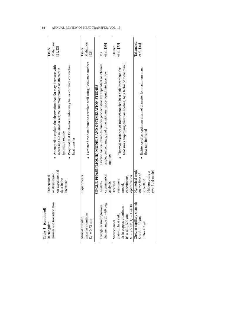
34 ANNUAL REVIEW OF HEAT TRANSFER, VOL. 13
Tabl
e1
(con
tinue
d)R
ecta
ngul
ar;
lam
inar
and
tran
sitio
nflo
wD
imen
sion
alan
alys
isba
sed
onex
perim
enta
lda
tain
the
liter
atur
e
•A
ttem
pted
toex
plai
nth
eob
serv
atio
nth
atN
um
ayde
crea
sew
ithin
crea
sing
Re
inla
min
arre
gim
ean
dm
ayre
mai
nun
aff
ecte
din
tran
sitio
nre
gim
e
•P
ropo
sed
that
Brin
kman
num
ber
may
bette
rco
rrel
ate
conv
ectiv
ehe
attr
ansf
er
Tso
&M
ahul
ikar
[21,
22]
Alm
ostc
ircul
ar;
wat
erin
alum
inum
Dh
=0.
73m
m
Exp
erim
ents
•La
min
arflo
wda
tafo
und
toco
rrel
ate
wel
lusi
ngB
rinkm
annu
mbe
rTso
&M
ahul
ikar
[23]
SIN
GLE
-PH
AS
E(L
IQU
ID)
MO
DE
LSA
ND
OP
TIM
IZAT
ION
ST
UD
IES
Tria
ngul
arm
icro
groo
ves
chan
nela
ngle
20–
60de
g.A
naly
ti-ca
l/num
eric
alan
alys
is
Fric
tion
fact
or-R
eyno
lds
num
ber
prod
ucts
tron
gly
depe
nden
ton
chan
nel
angl
e,co
ntac
tang
le,a
nddi
men
sion
less
vapo
r-liq
uid
inte
rfac
eflo
wnu
mbe
r
Ma
etal
.[56
]
Mic
roch
anne
lpl
ate-
finhe
atsi
nk;
air
inco
pper
,alu
min
umW
=40
0,50
0µm
,H
=2.
5cm
,Q=
1–
6l/s
The
rmal
resi
stan
cem
odel
,ex
perim
ents
,op
timiz
atio
n
•T
herm
alre
sist
ance
ofm
icro
chan
nele
dhe
atsi
nklo
wer
than
for
heat
sink
sem
ploy
ing
dire
ctai
rco
olin
g,by
afa
ctor
ofm
ore
than
3Kle
iner
etal
.[33
]
Circ
ular
capi
llary
chan
nels
D=
8.1
–96µm
,0.
76–
4.7µm
Num
eric
alst
udy
onth
eflo
wof
supe
rflui
dH
eliu
mus
ing
atw
o-flu
idm
odel
•E
xist
ence
ofan
optim
umch
anne
ldia
met
erfo
rm
axim
umm
ass
flow
rate
indi
cate
d
Taka
mat
suet
al.[
34]

TRANSPORT IN MICROCHANNELS – A CRITICAL REVIEW 35
Par
alle
lpla
tes
at25µ
mse
para
tion
dilu
teaq
ueou
sel
ectr
olyt
eL=
10m
m
The
oret
ical
anal
ysis
inco
rpor
atin
geff
ects
ofel
ectr
icdo
uble
laye
rfie
ld
•E
DL
resu
lted
ina
redu
ced
flow
velo
city
than
inco
nven
tiona
lth
eory
,thu
saff
ectin
gte
mpe
ratu
redi
strib
utio
nan
dre
duci
ngR
e
•H
ighe
rhe
attr
ansf
erpr
edic
ted
with
outt
hedo
uble
laye
r
Mal
aet
al.[
30]
Par
alle
lpla
tes
(10×2
0m
m)
ofP
-typ
esi
licon
and
glas
sat
10–
280µ
mse
para
tion;
∆P
=0
–35
0m
bar
Exp
erim
enta
lst
udy
and
com
paris
onw
ithpr
edic
ted
volu
me
flow
rate
s
•F
orso
lutio
nsof
high
ioni
cco
ncen
trat
ion
asw
ella
sfo
rD
h>
few
hund
redµ
m,E
DL
effec
tneg
ligib
leE
DL
effec
tbec
omes
sign
ifica
ntfo
rdi
lute
solu
tions
Mal
aet
al.[
31]
Rec
tang
ular
;di
lute
aque
ous
elec
trol
yte
insi
licon
H=
20µm
,W=
30µm
,L
=10
mm
,∆
P=
2at
m,T
i=
298
K,
q′′ =
1.0×
105W
/m2
Num
eric
alan
alys
isw
itheff
ects
ofE
DL
and
flow
-indu
ced
elec
trok
inet
icfie
ld
•T
heE
DL
field
and
elec
trok
inet
icpo
tent
iala
ctag
ains
tthe
liqui
dflo
w,r
esul
ting
inhi
gher
fric
tion
coeffi
cien
t,re
duce
dflo
wra
tean
da
redu
ceN
usse
ltnu
mbe
r,fo
rdi
lute
solu
tions
Yan
get
al.[
32]
Rec
tang
ular
(flat
plat
em
icro
heat
exch
ange
rs)
Opt
imiz
atio
nst
udy
onm
icro
chan
nel
shap
e
•W
idth
ofhe
atex
chan
ger
cond
uits
may
beop
timiz
edto
redu
cem
axim
umte
mpe
ratu
reof
the
unifo
rmly
heat
edsu
rfac
e
Bau
[35]

36 ANNUAL REVIEW OF HEAT TRANSFER, VOL. 13
Tabl
e1
(con
tinue
d)M
icro
chan
nelc
oolin
gan
dje
tim
ping
emen
tC
ompa
rativ
ean
alys
isof
jet
impi
ngem
ent
and
mic
roch
anne
lco
olin
g
•T
herm
alpe
rfor
man
ceof
jeti
mpi
ngem
entw
ithou
tany
trea
tmen
tof
spen
tflow
subs
tant
ially
low
erth
anm
icro
chan
nelc
oolin
g,re
gard
less
ofta
rget
dim
ensi
on
•M
icro
chan
nelc
oolin
gpr
efer
able
for
targ
etdi
men
sion
ssm
alle
rth
an7×
7cm
Lee
and
Vafa
i[36
]
GA
SF
LOW
Rec
tang
ular
;he
lium
insi
licon
W=
52.2
5µm
,H=
1.33
µm
,L
=75
00µm
;In
lett
oou
tlet
pres
sure
ratio
=1.
2–
2.5,
Re
=(0.5
–4)·1
0−3
Flo
wra
tes
mea
sure
dan
dco
mpa
red
with
theo
retic
alm
odel
•M
ass
flow
-pre
ssur
ere
latio
nshi
pac
cura
tely
mod
eled
byin
clud
ing
asl
ipflo
wbo
unda
ryco
nditi
onat
the
wal
l
Ark
ilic
etal
.[59
]
As
in[5
9]w
ithpr
essu
rera
tio=
1.6
–4.
2,R
e=
(1.4
–12
)·10−
3
Exp
erim
ents
and
com
paris
onof
mas
sflo
ww
ithre
sults
from
2Dan
alys
isw
ithsl
ipbo
unda
ryco
nditi
on
•D
iscu
ssio
nson
nond
imen
sion
alfo
rmul
atio
nan
dpe
rtur
batio
nso
lutio
n
Ark
ilic
etal
.[60
]

TRANSPORT IN MICROCHANNELS – A CRITICAL REVIEW 37
Mic
rotu
bes;
nitr
ogen
and
wat
erin
silic
aD
=19
,52,
102µ
m,
Pr=
0,7
–5,
Re
=25
0–
2000
0
Exp
erim
ents
;th
eore
tical
scal
ing
anal
ysis
•T
urbu
lent
mom
entu
man
den
ergy
tran
spor
tin
the
radi
aldi
rect
ion
sign
ifica
ntin
the
near
-wal
lzon
eof
am
icro
tube
•C
orre
latio
nspr
opos
ed:
f=
50.1
3/R
e(la
min
ar,R
e<
2000
)f
=0.
302/
Re0.
25(t
urbu
lent,
6000<
Re<
2000
0)N
u=
0.00
7R
e1.2
Pr0.
2(t
urbu
lent,
6000<
Re<
2000
0)
Yu etal
.[61
]
Rec
tang
ular
H=
0.5,
5µm
,H/W
=
2.5,
5,10,2
0(s
ubso
nic)
;5,
10,2
0(s
uper
soni
c)
Num
eric
alst
udy
usin
gdi
rect
sim
ulat
ion
Mon
teC
arlo
tech
niqu
e
•H
eatfl
uxon
the
chan
nels
urfa
cede
crea
ses
with
incr
ease
inK
nuds
ennu
mbe
ran
dch
anne
llen
gth
insu
pers
onic
flow
Mav
riplis
etal
.[62
]
Rec
tang
ular
;he
lium
(as
in[5
9]),
heliu
man
dni
trog
en,
Dh
=1.
01µm
,L=
10.9
mm
2Dnu
mer
ical
mod
el,
com
paris
onw
ithex
perim
ents
inlit
erat
ure
•N
usse
ltnu
mbe
ran
dfr
ictio
nco
effi
cien
tsub
stan
tially
redu
ced
for
slip
flow
sco
mpa
red
toco
ntin
uum
flow
s
•E
ffec
tofc
ompr
essi
bilit
ysi
gnifi
cant
athi
ghR
e
Kav
ehpo
ur& F
aghr
i[63
]
Sm
ooth
mic
rotu
bes
gas
flow
Num
eric
also
lutio
nof
gas
flow
inm
icro
tube
s
•Lo
calN
usse
ltnu
mbe
rin
crea
sed
with
dim
ensi
onle
ssle
ngth
,due
toco
mpr
essi
bilit
y
•f-
Re
prod
uctn
otco
nsta
nt;d
epen
dent
onR
e
Guo
&W
u[6
5]

38 ANNUAL REVIEW OF HEAT TRANSFER, VOL. 13
Tabl
e1
(con
tinue
d)R
ecta
ngul
ar;
nitr
ogen
,hel
ium
insi
licon
W=
40µm
,H=
1.2µm
,L
=3
mm
(N2)
,W=
52µm
,H
=1.
33µm
,L=
7.5
mm
(He)
Num
eric
also
lutio
nw
ithsl
ipbo
unda
ryco
nditi
on
•S
mal
lvel
ociti
esan
dhi
ghpr
essu
regr
adie
nts
due
tola
rge
wal
lshe
arst
ress
es
•C
ompa
rison
sw
ithex
perim
ents
of[5
9]
Che
net
al.[
66]
3Dst
raig
htan
dsp
iralg
roov
esN
umer
ical
stud
yon
slip
flow
inlo
ngm
icro
chan
nels
•N
on-li
near
pres
sure
grad
ient
sal
ong
the
mic
roch
anne
lsdu
eto
dens
ityva
riatio
ns
Niu
[67]
BO
ILIN
GIN
MIC
RO
CH
AN
NE
LSC
ircul
ar;R
-113
inco
pper
D=
2.45
mm
(min
i),51
0µm
(mic
ro),
Q=
19−
95m
l/min
,∆
T=
10–
32◦ C
Exp
erim
ents
onbo
iling
&tw
o-φ
flow
;bo
iling
curv
es&
CH
Fva
lues
obta
ined
•M
icro
chan
nely
ield
edhi
gher
CH
F(2
8%gr
eate
ratQ=
64m
l/min
)th
anm
inic
hann
el,w
itha
larg
er∆P
(0.3
bar
for
mic
ro,0
.03
bar
for
min
i)
Bow
ers
&M
udaw
ar[3
7]
As
in[3
7]P
ress
ure
drop
mod
elde
velo
ped;
pred
ictio
nsco
mpa
red
toex
perim
ents
•M
ajor
cont
ribut
orto
pres
sure
drop
iden
tified
asth
eac
cele
ratio
nre
sulti
ngfr
omev
apor
atio
n
•C
ompr
essi
bilit
yeff
ecti
mpo
rtan
tfor
mic
roch
anne
lwhe
nM
ach
num
ber>
0.22
•C
hann
eler
osio
neffec
tsm
ore
pred
omin
anti
nm
icro
chan
nels
than
inm
inic
hann
els
Bow
ers
&M
udaw
ar[3
8]
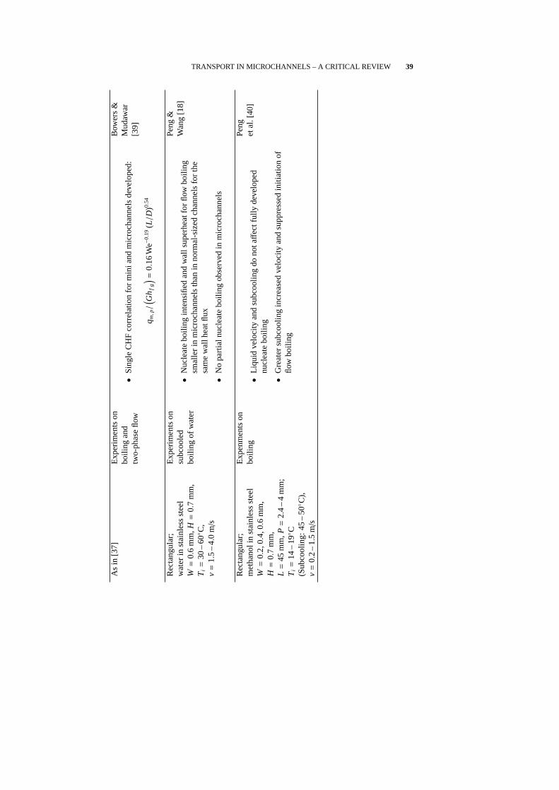
TRANSPORT IN MICROCHANNELS – A CRITICAL REVIEW 39
As
in[3
7]E
xper
imen
tson
boili
ngan
dtw
o-ph
ase
flow
•S
ingl
eC
HF
corr
elat
ion
for
min
iand
mic
roch
anne
lsde
velo
ped:
q m,p/( G
h fg
) =0.
16W
e−0.
19( L/D
)0.54
Bow
ers
&M
udaw
ar[3
9]
Rec
tang
ular
;w
ater
inst
ainl
ess
stee
lW
=0.
6m
m,H
=0.
7m
m,
Ti=
30–
60◦ C
,v
=1.
5–
4.0
m/s
Exp
erim
ents
onsu
bcoo
led
boili
ngof
wat
er•
Nuc
leat
ebo
iling
inte
nsifi
edan
dw
alls
uper
heat
for
flow
boili
ngsm
alle
rin
mic
roch
anne
lsth
anin
norm
al-s
ized
chan
nels
for
the
sam
ew
allh
eatfl
ux
•N
opa
rtia
lnuc
leat
ebo
iling
obse
rved
inm
icro
chan
nels
Pen
g&
Wan
g[1
8]
Rec
tang
ular
;m
etha
noli
nst
ainl
ess
stee
lW
=0.
2,0.
4,0.
6m
m,
H=
0.7
mm
,L
=45
mm
,P=
2.4
–4
mm
;T
i=
14–
19◦ C
(Sub
cool
ing:
45–
50◦C
),v
=0.
2–
1.5
m/s
Exp
enm
ents
onbo
iling
•Li
quid
velo
city
and
subc
oolin
gdo
notaff
ectf
ully
deve
lope
dnu
clea
tebo
iling
•G
reat
ersu
bcoo
ling
incr
ease
dve
loci
tyan
dsu
ppre
ssed
initi
atio
nof
flow
boili
ng
Pen
get
al.[
40]
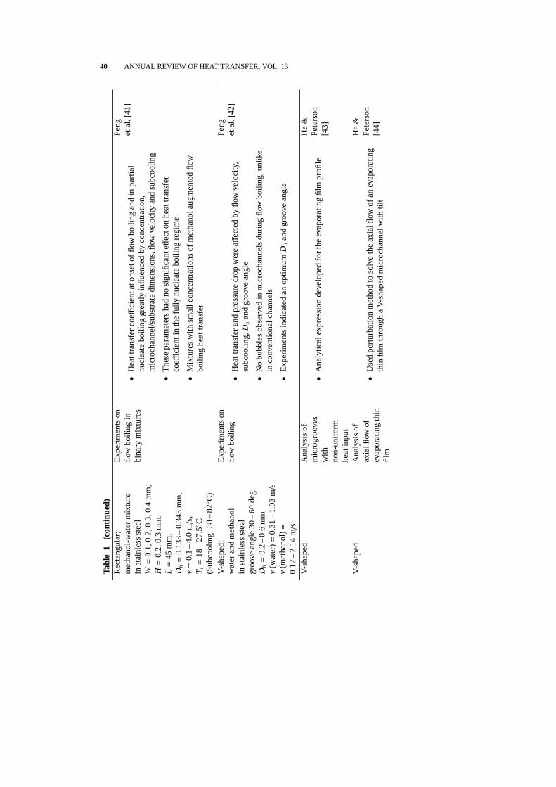
40 ANNUAL REVIEW OF HEAT TRANSFER, VOL. 13
Tabl
e1
(con
tinue
d)R
ecta
ngul
ar;
met
hano
l-wat
erm
ixtu
rein
stai
nles
sst
eel
W=
0.1,
0.2,
0.3,
0.4
mm
,H
=0.
2,0.
3m
m,
L=
45m
m,
Dh
=0.
133
–0.3
43m
m,
v=
0.1
–4.
0m
/s,
Ti=
18–
27.5◦ C
(Sub
cool
ing:
38–
82◦C
)
Exp
erim
ents
onflo
wbo
iling
inbi
nary
mix
ture
s•
Hea
ttra
nsfe
rco
effici
enta
tons
etof
flow
boili
ngan
din
part
ial
nucl
eate
boili
nggr
eatly
influ
ence
dby
conc
entr
atio
n,m
icro
chan
nel/sub
stra
tedi
men
sion
s,flo
wve
loci
tyan
dsu
bcoo
ling
•T
hese
para
met
ers
had
nosi
gnifi
cant
eff
ecto
nhe
attr
ansf
erco
effici
enti
nth
efu
llynu
clea
tebo
iling
regi
me
•M
ixtu
res
with
smal
lcon
cent
ratio
nsof
met
hano
laug
men
ted
flow
boili
nghe
attr
ansf
er
Pen
get
al.[
41]
V-s
hape
d;w
ater
and
met
hano
lin
stai
nles
sst
eel
groo
vean
gle
30–
60de
g;D
h=
0.2
–0.
6m
mv
(wat
er)=
0.31
–1.
03m
/sv
(met
hano
l)=0.
12–
2.14
m/s
Exp
erim
ents
onflo
wbo
iling
•H
eatt
rans
fer
and
pres
sure
drop
wer
ea
ffec
ted
byflo
wve
loci
ty,
subc
oolin
g,D
han
dgr
oove
angl
e
•N
obu
bble
sob
serv
edin
mic
roch
anne
lsdu
ring
flow
boili
ng,u
nlik
ein
conv
entio
nalc
hann
els
•E
xper
imen
tsin
dica
ted
anop
timumD
han
dgr
oove
angl
e
Pen
get
al.[
42]
V-s
hape
dA
naly
sis
ofm
icro
groo
ves
with
non-
unifo
rmhe
atin
put
•A
naly
tical
expr
essi
onde
velo
ped
for
the
evap
orat
ing
film
profi
le
Ha
&P
eter
son
[43]
V-s
hape
dA
naly
sis
ofax
ialfl
owof
evap
orat
ing
thin
film
•U
sed
pert
urba
tion
met
hod
toso
lve
the
axia
lflow
ofan
evap
orat
ing
thin
film
thro
ugh
aV
-sha
ped
mic
roch
anne
lwith
tilt
Ha
&P
eter
son
[44]
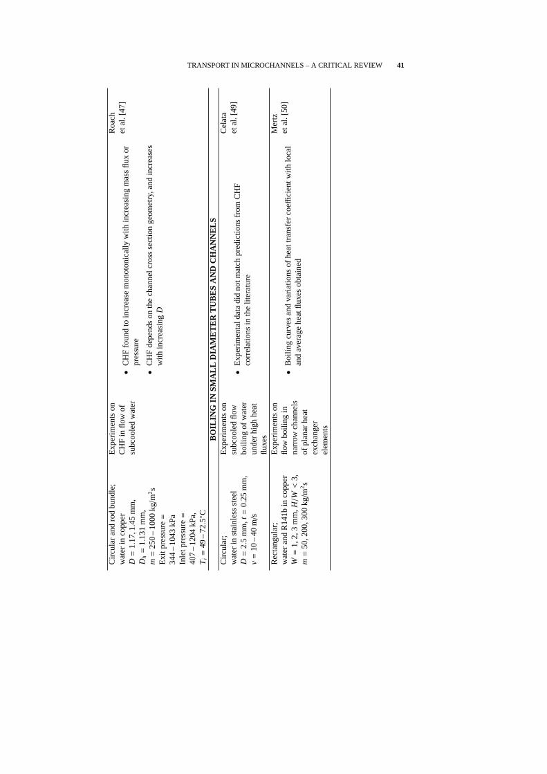
TRANSPORT IN MICROCHANNELS – A CRITICAL REVIEW 41
Circ
ular
and
rod
bund
le;
wat
erin
copp
erD
=1.
17,1.4
5m
m,
Dh
=1.
131
mm
,m
=25
0–
1000
kg/m
2s
Exi
tpre
ssur
e=34
4–
1043
kPa
Inle
tpre
ssur
e=40
7–
1204
kPa,
Ti=
49–
72.5◦ C
Exp
erim
ents
onC
HF
inflo
wof
subc
oole
dw
ater
•C
HF
foun
dto
incr
ease
mon
oton
ical
lyw
ithin
crea
sing
mas
sflu
xor
pres
sure
•C
HF
depe
nds
onth
ech
anne
lcro
ssse
ctio
nge
omet
ry,a
ndin
crea
ses
with
incr
easi
ngD
Roa
chet
al.[
47]
BO
ILIN
GIN
SM
ALL
DIA
ME
TE
RT
UB
ES
AN
DC
HA
NN
ELS
Circ
ular
;w
ater
inst
ainl
ess
stee
lD
=2.
5m
m,t
=0.
25m
m,
v=
10–
40m/
s
Exp
erim
ents
onsu
bcoo
led
flow
boili
ngof
wat
erun
der
high
heat
fluxe
s
•E
xper
imen
tald
ata
did
notm
atch
pred
ictio
nsfr
omC
HF
corr
elat
ions
inth
elit
erat
ure
Cel
ata
etal
.[49
]
Rec
tang
ular
;w
ater
and
R14
1bin
copp
erW
=1,
2,3
mm
,H/W
<3,
m=
50,2
00,3
00kg/
m2s
Exp
erim
ents
onflo
wbo
iling
inna
rrow
chan
nels
ofpl
anar
heat
exch
ange
rel
emen
ts
•B
oilin
gcu
rves
and
varia
tions
ofhe
attr
ansf
erco
effi
cien
twith
loca
lan
dav
erag
ehe
atflu
xes
obta
ined
Mer
tzet
al.[
50]

42 ANNUAL REVIEW OF HEAT TRANSFER, VOL. 13
Tabl
e1
(con
tinue
d)R
ecta
ngul
ar;
FC
-72
infib
ergl
ass
W=
5m
m,H
=2.
5m
m,
Hea
ted
leng
th=10
1.6
mm
,v
=0.
25–
10m/
s,R
e=
2000
–13
0000
Sub
cool
ing
atou
tlet=
3,16
,29◦ C
CH
Fex
perim
ents
onlo
ngch
anne
ls;
flow
visu
aliz
atio
n
•P
ropa
gatio
nof
vapo
rpa
tche
sre
sem
blin
ga
wav
yva
por
laye
ral
ong
the
heat
edw
alla
tthe
criti
calh
eatfl
ux
•Le
ngth
and
heig
htof
vapo
rpa
tch
foun
dto
incr
ease
alon
gflo
wdi
rect
ion,
and
decr
ease
dw
ithin
crea
sing
subc
oolin
gan
dve
loci
ty
Stu
rgis
&M
udaw
ar[5
1]
As
in[5
1]T
heor
etic
alm
odel
for
CH
F;
data
anal
ysis
•E
ffec
tofp
erio
dic
dist
ribut
ion
ofva
por
patc
hes
idea
lized
asa
sinu
soid
alin
terf
ace
with
ampl
itude
and
wav
elen
gth
incr
easi
ngin
flow
dire
ctio
n
Stu
rgis
&M
udaw
ar[5
1]
TW
O-P
HA
SE
FLO
WR
ecta
ngul
ar;
R12
4in
copp
erW
=0.
27m
m,H
=1.
0m
m,
Dh
=42
5m
m,
Re D
h=
100
–75
0;q′′ <
40W
/cm
2
Exp
erim
ents
onm
icro
chan
nel
heat
exch
ange
r•
Nus
selt
num
ber
(−5to
12)
show
edan
incr
ease
with
Rey
nold
snu
mbe
rin
sing
le-φ
flow
,but
was
appr
oxim
atel
yco
nsta
ntin
two-φ)
flow
Cut
aet
al.[
45]
Rec
tang
ular
;R
124
inco
pper
W=
270µm
,H=
1000µm
,L
=2.
052
cm,D
h=
425µm
;In
lets
ubco
olin
g:5
–15◦
C;
Q=
35–
300
ml/m
in
Exp
erim
ents
with
two
mic
roch
anne
lpa
ttern
s(p
aral
lela
nddi
amon
d)
•H
eatt
rans
fer
coeffi
cien
tand
pres
sure
drop
foun
dto
befu
nctio
nsof
flow
qual
ityan
dm
ass
flux,
inad
ditio
nto
the
heat
flux
and
surf
ace
supe
rhea
t
•H
eatt
rans
fer
coeffi
cien
tdec
reas
edby
20–
30%
for
anin
crea
sein
exit
vapo
rqu
ality
from
0.01
to0.
65
Rav
igur
u-ra
jan
[46]

TRANSPORT IN MICROCHANNELS – A CRITICAL REVIEW 43
Circ
ular
and
sem
i-tria
ngul
ar;
air-
wat
erm
ixtu
rein
glas
sD
=1.
1,1.
45m
m,
Dh
=1.
09,1.4
9m
m,v
(air)
:0.
02–
80m/
s,v
(wat
er):
0.02
–8
m/s
(sup
erfic
ial
velo
city
)
Vis
ual
obse
rvat
ion
offlo
wpa
ttern
san
dpa
ttern
map
s
•B
ubbl
y,ch
um,s
lug,
slug
-ann
ular
and
annu
lar
flow
patte
rns
obse
rved
Trip
lett
etal
.[54
]
As
in[5
4]F
rictio
nal
pres
sure
drop
sm
easu
red
and
com
pare
dw
ithva
rious
two-φ
fric
tion
mod
els
•M
odel
san
dco
rrel
atio
nsov
erpr
edic
ted
chan
nelv
oid
frac
tion
and
pres
sure
drop
inan
nula
rflo
wpa
ttern
•A
nnul
arflo
win
terf
ace
mom
entu
mtr
ansf
eran
dw
allf
rictio
nin
mic
roch
anne
lssi
gnifi
cant
lydiffer
entf
rom
thos
ein
larg
erch
anne
ls
Trip
lett
etal
.[55
]
Circ
ular
and
rect
angu
lar;
air-
wat
erm
ixtu
rein
glas
sD
h=
1.3
–5.
5m
m;
v=
0.1
–10
0m/
s(g
as);
v=
0.01
–10
m/s
(liqu
id)
Exp
erim
ents
,flo
wvi
sual
izat
ion
•T
ube
diam
eter
influ
ence
sth
esu
perfi
cial
gas
and
liqui
dve
loci
ties
atw
hich
flow
tran
sitio
nsta
kepl
ace,
due
toco
mbi
ned
eff
ecto
fsu
rfac
ete
nsio
n,hy
drau
licdi
amet
eran
das
pect
ratio
Col
eman
&G
arim
ella
[53]
DE
SIG
NA
ND
TE
ST
ING
Rec
tang
ular
;wat
erin
silic
onN
umer
ical
solu
tion
for
tem
pera
ture
field
;co
mpa
rison
with
expe
rimen
ts
•D
esig
nal
gorit
hmde
velo
ped
for
sele
ctio
nof
heat
exch
ange
rdi
men
sion
s
•E
xpre
ssio
nfo
rm
axim
umpu
mpi
ngpo
wer
obta
ined
asfu
nctio
nof
chan
nelg
eom
etry
Wei
sber
get
al.[
58]

44 ANNUAL REVIEW OF HEAT TRANSFER, VOL. 13
Tabl
e1
(con
tinue
d)A
lmos
trec
tang
ular
;w
ater
inco
pper
0.5×
12m
m,0.1
25×1
2m
m,
Q=
0.47
–5
gpm
Des
ign
and
test
ing,
mic
roch
anne
lhe
atex
chan
ger
for
lase
rdi
ode
arra
ys
•T
herm
alre
sist
ance
due
toso
lder
bond
estim
ated
Roy
&A
vani
c[6
9]
Rec
tang
ular
and
alm
ostt
riang
ular
;ai
rin
copp
er,a
lum
inum
Par
amet
ricst
udie
san
dex
perim
ents
ofai
rim
ping
emen
tin m
icro
chan
nels
•T
herm
alre
sist
ance
mod
elde
velo
ped
•P
aram
etric
stud
ies
tode
term
ine
influ
ence
ofst
atic
pres
sure
,pu
mpi
ngpo
wer
and
geom
etric
para
met
ers
onth
erm
alre
sist
ance
Ara
nyos
iet
al.[
70]
Rec
tang
ular
,di
amon
d-sh
aped
and
hexa
gona
l;w
ater
insi
licon
3Dnu
mer
ical
mod
el;
optim
izat
ion
for
redu
cing
ther
mal
resi
stan
ce
•R
ecta
ngul
arge
omet
ryha
dth
elo
wes
tthe
rmal
resi
stan
ce
Per
ret
etal
.[72
]
Rec
tang
ular
;w
ater
,FC
72in
copp
erE
xper
imen
tson
mic
rohe
atsi
nkfo
rpo
wer
mul
tichi
pm
odul
e;3D
and
IDth
erm
alre
sist
ance
mod
els
•P
ower
dens
ities
of23
0–
350
W/cm
2di
ssip
ated
with
ate
mpe
ratu
reris
eof
35◦ C
,and
apu
mpi
ngpo
wer
ofab
out1
Wpe
rch
ip
•P
aram
eter
’hea
tspr
ead
eff
ect’
defin
edS
=( R
th1D−
Rth
3D) /
Rth
1D
Gill
otet
al.[
71]
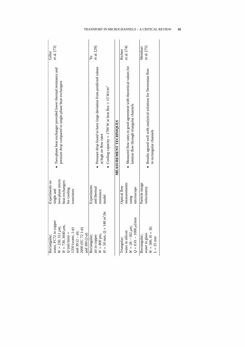
TRANSPORT IN MICROCHANNELS – A CRITICAL REVIEW 45
Rec
tang
ular
;w
ater
,FC
72in
copp
erW
=23
0,31
1µm
,H
=73
0,30
40µm
,Q
(ml/
min
)=13
50(w
ater
,1-φ)
and
30(2−φ);
2000
(FC
721-φ
)an
d30
0(2
-φ)
Exp
erim
ents
onsi
ngle
and
two-
phas
em
icro
heat
exch
ange
rsfo
rco
olin
gtr
ansi
stor
s
•Tw
o-ph
ase
heat
exch
ange
rpr
ovid
edlo
wer
ther
mal
resi
stan
cean
dpr
essu
redr
opco
mpa
red
tosi
ngle
-pha
sehe
atex
chan
gers
Gill
otet
al.[
73]
Rec
tang
ular
;ai
rin
copp
erW
=80
0pm
,H
=50
mm
,Q=
140
m3/h
r
Exp
erim
ents
and
ther
mal
resi
stan
cem
odel
•P
ress
ure
drop
foun
dto
have
larg
ede
viat
ion
from
pred
icte
dva
lues
athi
ghai
rflo
wra
tes
•C
oolin
gca
paci
ty≈17
00W
athe
atflu
x≈15
W/c
m2
Yu etal
.[29
]
ME
AS
UR
EM
EN
TT
EC
HN
IQU
ES
Tria
ngul
ar;
wat
erin
silic
onW
=28−
182µm
,Q
=0.
01−
1000µl/m
in
Opt
ical
flow
mea
sure
men
tsus
ing
mic
rosc
ope
•M
easu
red
flow
rate
sin
good
agre
emen
twith
theo
retic
alva
lues
for
lam
inar
flow
thro
ugh
tria
ngul
arch
anne
ls
Ric
hter
etal
.[74
]
Rec
tang
ular
;w
ater
ingl
ass
W=
300,
H=
30,
L=
25m
m
Par
ticle
imag
eve
loci
met
ry•
Res
ults
agre
edw
ellw
ithan
alyt
ical
solu
tions
for
New
toni
anflo
win
rect
angu
lar
chan
nels
Mei
nhar
tet
al.[
75]

46 ANNUAL REVIEW OF HEAT TRANSFER, VOL. 13
REFERENCES
1. R. J. Phillips, L. R. Glicksman, and R. Larson, Forced-Convection, Liquid Cooled,Microchannel Heat Sinks for High Power-Density Microelectronics, in:Proc.Int. Symp. on Cooling Technology for Electronic Equipment, Honolulu, Hawaii,pp. 295–316, 1987.
2. D. B. Tuckerman and R. F. W. Pease, High-Performance Heat Sinking for VLSI,IEEE Electron. Device Lett., Vol. EDL-2, pp. 126–129, 1981.
3. D. B. Tuckerman and R. F. W. Pease, Ultrahigh Thermal Conductance Microstruc-tures for Cooling Integrated Circuits, in:Procs. 32-nd Electronic ComponentsConf., IEEE, EIA, CHMT, pp. 145–149, 1982.
4. P. Y. Wu and W. A. Little, Measurement of Friction Factor for the Flow of Gasesin Very Fine Channels used for Micro Miniature Joule Thompson Refrigerators,Cryogenics, Vol. 23, pp. 273–277, 1983.
5. P. Y. Wu and W. A. Little, Measurement of the Heat Transfer Characteristics ofGas Flow in Fine Channel Heat Exchangers for Micro Miniature Refrigerators,Cryogenics, Vol. 24, pp. 415–420, 1984.
6. D. B. Tuckerman,Heat Transfer Microstructures for Integrated Circuits, Ph.D.Thesis, Stanford University, Stanford, CA, 1984.
7. M. Mahalingam and J. Andrews, High Performance Air Cooling for Microelectron-ics, in: Proc. Int. Symp. on Cooling Technology for Electronic Equipment, Hon-olulu, Hawaii, pp. 608–625, 1987.
8. J. Pfahler, J. Harley, H. H. Bau, and J. Zemel, Liquid Transport in Micron andSubmicron Channels,J. Sensors Actuators A, Vol. 21–23, pp. 431–434, 1990.
9. S. B. Choi, R. F. Barron, and R. O. Warrington, Fluid Flow and Heat Transferin Microtubes,Micromechanical Sensors, Actuators and Systems, ASME DSC-Vol. 32, pp. 123–134, 1991.
10. M. M. Rahman and F. Gui, Experimental Measurements of Fluid Flow and HeatTransfer in Microchannel Cooling Passages in a Chip Substrate,Advances in Elec-tronic Packaging, ASME EEP-Vol. 4–2, pp. 685–692, 1993.
11. T. L. Hoopman, Microchanneled Structures,Microstructures, Sensors and Actua-tors, ASME DSC-108, pp. 171–174, 1990.
12. J. S. Goodling and R. W. Knight, Optimal Design of Microchannel Heat Sinks – AReview, in:Optimal Design of Thermal Systems and Components, 65–78, pp. 1994,.
13. X. F. Peng, G. P. Peterson, and B. X. Wang, Frictional Flow Characteristics of WaterFlowing through Microchannels,Experiment. Heat Transfer, Vol. 7, pp. 249–264,1994.
14. X. F. Peng, G. P. Peterson, and B. X. Wang, Heat Transfer Characteristics of WaterFlowing through Microchannels,Experiment. Heat Transfer, Vol. 7, pp. 265–283,1994.
15. X. F. Peng and G. P. Peterson, Convective Heat Transfer and Flow Friction for Wa-ter Flow in Microchannel Structures,Int. J. Heat Mass Transfer, Vol. 39, pp. 2599–2608, 1996.
16. B. X. Wang and X. F. Peng, Experimental Investigation on Liquid Forced Con-vection Heat Transfer through Microchannels,Int. J. Heat Mass Transfer, Vol. 37,pp. 73–82, 1994.
17. X. F. Peng and G. P. Peterson, The Effect of Thermofluid and Geometrical Param-

TRANSPORT IN MICROCHANNELS – A CRITICAL REVIEW 47
eters on Convection of Liquids Through Rectangular Microchannels,Int. J. HeatMass Transfer, Vol. 38, pp. 755–758, 1995.
18. X. F. Peng and B. X. Wang, Forced Convection and Flow Boiling Heat transferfor liquid flowing through microchannels,Int. J. Heat Mass Transfer, Vol. 36,pp. 3421–3427, 1993.
19. X. F. Peng and G. P. Peterson, Forced Convection Heat Transfer of Single PhaseBinary Mixtures through Microchannels,Experiment. Thermal Fluid Sci., Vol. 12,pp. 98–104, 1996.
20. T. M. Harms, M. Kazmierczak, F. M. Gerner, A. Holke, H. T. Henderson, J. Pil-chowski, and K. Baker, Experimental Investigation of Heat Transfer and PressureDrop through Deep Microchannels in a (110) Silicon Substrate, in:Proc. ASMEHeat Transfer Div., ASME HTD-Vol. 351–1, pp. 347–357, 1997.
21. C. P. Tso and S. P. Mahulikar, Use of the Brinkman Number for Single PhaseForced Convective Heat Transfer in Microchannels,Int. J. Heat Mass Transfer,Vol. 41, pp. 1759–1769, 1998.
22. C. P. Tso and S. P. Mahulikar, Role of the Brinkman Number in Analyzing FlowTransitions in Microchannels,Int. J. Heat Mass Transfer, Vol. 42, pp. 1813–1833,1999.
23. C. P. Tso and S. P. Mahulikar, Experimental Verification of the Role of BrinkmanNumber in Microchannels using Local Parameters,Int. J. Heat Mass Transfer,Vol. 43, pp. 1837–1849, 2000.
24. T. M. Adams, S. I. Abdel-Khalik, S. M. Jeter, and Z. H. Qureshi, An ExperimentalInvestigation of Single-Phase Forced Convection in Microchannels,Int. J. HeatMass Transfer, Vol. 41, pp. 851–857, 1998.
25. V. Gnielinski, New Equations for Heat and Mass Transfer in Turbulent Pipe andChannel Flow,Int. Chem. Engng, Vol. 16, pp. 359–368, 1976.
26. G. Filonenko, Hydraulic Resistance in Pipes,Teploenergetika, Vol. 1, pp. 40–44,1954 [in Russian].
27. T. M. Adams, C. F. Dowling, S. I. Abdel-Khalik, and S. M. Jeter, Applicabil-ity of Traditional Turbulent Single Phase Forced Convection Correlations to Non-Circular Microchannels,Int. J. Heat Mass Transfer, Vol. 42, pp. 4411–4415, 1999.
28. Y. Zhuang, C. F. Ma, and M. Qin, Experimental Study on Local Heat Transfer withLiquid Impingement Flow in Two Dimensional Micro-Channels,Int. J. Heat MassTransfer, Vol. 40, pp. 4055–4059, 1997.
29. S. Yu, T. Ameel, and M. Xin, An Air-Cooled Microchannel Heat Sink with HighHeat Flux and Low Pressure Drop, in:Proc. 33-rd Nat. Heat Transfer Conf., Albu-querque, New Mexico, Paper No. NHTC 99-162, pp. 1–7, 1999.
30. G. M.Mala, D. Li, and J. D. Dale, Heat Transfer and Fluid Flow in Microchannels,Int. J. Heat Mass Transfer, Vol. 40, pp. 3079–3088, 1997.
31. G. M. Mala, D. Li, C. Werner, H. J. Jacobasch, and Y. B. Ning, Flow Characteristicsof Water through a Microchannel between Two Parallel Plates with ElectrokineticEffects,Int. J. Heat Fluid Flow, Vol. 18, pp. 489–496, 1997.
32. C. Yang, D. Li, and J. H. Masliyah, Modeling Forced Liquid Convection in Rect-angular Microchannels with Electrokinetic Effects, Int. J. Heat Mass Transfer,Vol. 41, pp. 4229–4249, 1998.
33. M. B. Kleiner, S. A. Kuehn, and K. Haberger, High Performance Forced Air Cool-ing Scheme employing Microchannel Heat Exchangers,IEEE Trans. Components,Pack. Manuf. Technol. Part A, Vol. 18, pp. 795–804, 1995.

48 ANNUAL REVIEW OF HEAT TRANSFER, VOL. 13
34. K. Takamatsu, N. Fujimoto, Y. F. Rao, and K. Fukuda, Numerical Study of Flowand Heat Transfer of Superfluid Helium in Capillary Channels,Cryogenics, Vol. 37,pp. 829–835, 1997.
35. H. H. Bau, Optimization of Conduits’ Shape in Microscale Heat Exchangers,Int. J.Heat Mass Transfer, Vol. 41, pp. 2717–2723, 1998.
36. D. Y. Lee and K. Vafai, Comparative Analysis of Jet Impingement and Microchan-nel Cooling for High Heat Flux Applications,Int. J. Heat Mass Transfer, Vol. 42,pp. 1555–1568, 1999.
37. M. B. Bowers, and I. Mudawar, Two Phase Electronic Cooling using Mini-Channeland Micro-Channel Heat Sinks. Part 1: Design Criteria and Heat Diffusion Con-straints,ASME J. Electron. Pack., Vol. 116, pp. 290–297, 1994.
38. M. B. Bowers, and I. Mudawar, Two Phase Electronic Cooling using Mini-Channeland Micro-Channel Heat Sinks. Part 2: Flow Rate and Pressure Drop Constraints,ASME J. Electron. Pack., Vol. 116, pp. 298–305, 1994.
39. M. B. Bowers, and I. Mudawar, High Flux Boiling in Low Flow Rate, Low PressureDrop Mini-Channel and Micro-Channel Heat Sinks,Int. J. Heat Mass Transfer,Vol. 37, pp. 321–332, 1994.
40. X. F. Peng, B. X. Wang, G. P. Peterson, and H. B. Ma, Experimental Investigationof Heat Transfer in Flat Plates with Rectangular Microchannels,Int. J. Heat MassTransfer, Vol. 38, pp. 127–137, 1995.
41. X. F. Peng, G. P. Peterson, and B. X. Wang, Flow Boiling of Binary Mixtures inMicrochannel Plates,Int. J. Heat Mass Transfer, Vol. 39, pp. 1257–1264, 1996.
42. X. F. Peng, H. Y. Hu, and B. X. Wang, Flow Boiling through V-Shape Microchan-nels,Experiment. Heat Transfer, Vol. 11, pp. 87–90, 1998.
43. J. M. Ha and G. P. Peterson, The Interline Heat Transfer of Evaporating Thin FilmsAlong A Micro Grooved Surface,ASME J. Heat Transfer, Vol. 118, pp. 747–755,1996.
44. J. M. Ha and G. P. Peterson, Capillary Performance of Evaporating Flow in Mi-crogrooves – An Analytical Approach for Very Small Tilt Angles,ASME J. HeatTransfer, Vol. 120, pp. 452–457, 1998.
45. J. M. Cuta, C. E. McDonald, and A. Shekarriz, Forced Convection Heat Trans-fer in Parallel Channel Array Microchannel Heat Exchanger,Advances in EnergyEfficiency, Heat/Mass Transfer Enhancement, ASME PID-Vol. 2/HTD, Vol. 338,pp. 17–23, 1996.
46. T. S. Ravigururajan, Impact of Channel Geometry on Two Phase Flow Heat Trans-fer Characteristics of Refrigerants in Microchannel Heat Exchangers,ASME J.Heat Transfer, Vol. 120, pp. 485–491, 1998.
47. G. M. Roach Jr., S. I. Abdel-Khalik, S. M. Ghiaasiaan, M. F. Dowling, andS. M. Jeter, Low-Flow Critical Heat Flux in Heated Microchannels,Nuclear Sci-ence and Engineering, Vol. 131, pp. 411–425, 1999.
48. R. W. Bowring, A Simple but Accurate Round Tube, Uniform Heat Flux, DryoutCorrelation over the Pressure Range 0.7 – 17 MW/m2 (100 – 2500 psia),AEEW-R789, United Kingdom Atomic Energy Authority, 1972.
49. G. P. Celata, M. Cumo, and A. Mariani, Burnout in Highly Subcooled Water FlowBoiling in Small Diameter Tubes,Int. J. Heat Mass Transfer, Vol. 36, pp. 1269–1285, 1993.
50. R. Mertz., A. Wein, and M. Groll, Experimental Investigation of Flow Boiling HeatTransfer in Narrow Channels,Heat and Technology, Vol. 14, pp. 47–54, 1996.
TRANSPORT IN MICROCHANNELS – A CRITICAL REVIEW 49
51. J. C. Sturgis and I. Mudawar, Critical Heat Flux in a Long, Rectangular ChannelSubjected to One-Sided Heating – I. Flow Visualization,Int. J. Heat Mass Transfer,Vol. 42, pp. 1835–1847, 1999.
52. J. C. Sturgis and I. Mudawar, Critical Heat Flux in a Long, Rectangular ChannelSubjected to One-Sided Heating – II. Analysis of Critical Heat Flux Data,Int. J.Heat Mass Transfer, Vol. 42, pp. 1849–1862, 1999.
53. J. M. Coleman and S. Garimella, Characterization of Two-Phase Flow Patterns inSmall Diameter Round and Rectangular Tubes,Int. J. Heat Mass Transfer, Vol. 42,pp. 2869–2881, 1999.
54. K. A. Triplett, S. M. Ghiaasiaan, S. I. Abdel-Khalik, and D. L. Sadowski, Gas-Liquid Two Phase Flow in Microchannels. Part I: Two Phase Flow Patterns,Int. J.Multiphase Flow, Vol. 25, pp. 377–394, 1999.
55. K. A. Triplett, S. M. Ghiaasiaan, S. I. Abdel-Khalik, A. LeMouel, and B. N. Mc-Cord, Gas-Liquid Two Phase Flow in Microchannels. Part II: Void Fraction andPressure Drop,Int. J. Multiphase Flow, Vol. 25, pp. 395–410, 1999.
56. P. B. Ma, G. P. Peterson and X. J. Lu, Influence of Vapor-Liquid Interactions onthe Liquid Pressure Drop in Triangular Microgrooves,Int. J. Heat Mass Transfer,Vol. 37, pp. 2211–2219, 1994.
57. E. M. Sparrow, T. S. Chen, and V. K. Jonsson, Laminar Flow and Pressure Drop inInternally Finned Annular Ducts,Int. J. Heat Mass Transfer, Vol. 7, pp. 583–585,1964.
58. P. S. Ayyaswamy, I. Catton, and D. K. Edwards, Capillary Flow in TriangularGrooves,ASME J. Appl. Mech., Vol. 41, pp. 332–336, 1974.
59. E. B. Arkilic, K. S. Breuer, and M. A. Schmidt, Gaseous Flow in Microchannels,Application of Microfabrication to Fluid Mechanics, ASME FED, Vol. 197, pp. 57–66, 1994.
60. E. B. Arkilic, M. A. Schmidt, and K. S. Breuer, Gaseous Slip Flow in Long Mi-crochannels,IEEE J. Microelectromechanical Systems, Vol. 6, pp. 167–178, 1997.
61. D. Yu, R. Warrington, R. Barron, and T. Ameel, An Experimental and Theoreti-cal Investigation of Fluid Flow and Heat Transfer in Microtubes, in:ASME/JSMEThermal Engng Conf., Vol. 1, pp. 523–530, 1995.
62. C. Mavriplis, J. C. Ahn, and R. Goulard, Heat Transfer and Flow Fields in Short Mi-crochannels using Direct Simulation Monte Carlo,Thermophysics and Heat Trans-fer, Vol. 11, pp. 489–496, 1997.
63. H. P. Kavehpour, M. Faghri, and Y. Asako, Effects of Compressibility and Rar-efaction on Gaseous Flows in Microchannels,Numerical Heat Transfer, Vol. 32A,pp. 677–696, 1997.
64. J. Pfahler, J. Harley, H. H. Bau, and J. Zemel, Gas and Liquid Flow in Small Chan-nels,Micromechanical Sensors, Actuators and Systems, ASME DSC-32, pp. 49–60, 1991.
65. Z. Y. Guo and X. B. Wu, Compressibility Effect on the Gas Flow and Heat Transferin a Micro Tube,Int. J. Heat Mass Transfer, Vol. 40, pp. 3251–3254, 1997.
66. C. S. Chen, S. M. Lee,and J. D. Sheu, Numerical Analysis of Gas Flow in Mi-crochannels,Numerical Heat Transfer, Vol. 33A, pp. 749–762, 1998.
67. Y. Y. Niu, Navier – Stokes Analysis of Gaseous Slip Flow in Long Grooves,Nu-merical Heat Transfer, Vol. 36A, pp. 75–93, 1999.
68. A. Weisberg, H. H. Bau, and J. Zemel, Analysis of Microchannels for IntegratedCooling,Int. J. Heat Mass Transfer, Vol. 35, pp. 2465–2474, 1992.
50 ANNUAL REVIEW OF HEAT TRANSFER, VOL. 13
69. S. K. Roy and B. L. Avanik, Very High Heat Flux Microchannel Heat Exchangerfor Cooling of Semiconductor Laser Diode Arrays,IEEE Trans. Components, Pack.Manuf. Technol. Part B: Advanced Packaging, Vol. 19, pp. 444–451, 1996.
70. A. Aranyosi, L. M. R. Bolle, and H. A. Buyse, Compact Air-Cooled Heat Sinks forPower Packages,IEEE Trans. Components, Pack. Manuf. Technol. Part A, Vol. 20,pp. 442–451, 1997.
71. C. Gillot, C. Schaeffer, and A. Bricard, Integrated Micro Heat Sink for Power Mul-tichip Module, in:IEEE Industry Applications Soc. Ann. Meet., Vol. 2, 98CH36242,pp. 1046–1050, 1998.
72. C. Perret, C. Schaeffer, and J. Boussey, Microchannel Integrated Heat Sinksin Silicon Technology, in:IEEE Industry Applications Soc. Ann. Meet., Vol. 2,98CH36242, pp. 1051–1055, 1998.
73. C. Gillot, L. Meysenc, and C. Schaeffer, Integrated single and two phase microheat sinks under IGBT chips,IEEE Transactions on Components and PackagingTechnology, Vol. 22, pp. 384–389, 1999.
74. M. Richter, P. Woias, and D. Wei, Microchannels for Applications in Liquid Dosingand Flow Rate Measurement,Sensors and Actuators A, Vol. 62, pp. 480–483, 1997.
75. C. D. Meinhart, S. T. Wereley, and J. G. Santiago, PIV Measurements of a Mi-crochannel Flow,Exp. Fluids, Vol. 27, pp. 414–419, 1999.
76. C. B. Sobhan and S. V. Garimella, A Comparative Analysis of Studies on HeatTransfer and Fluid Flow in Microchannels, in:Heat Transfer and Transport Phe-nomena in Microsystems, Banff, Canada, October 15-20, pp. 80–92, 2000.