Embed Size (px)
Citation preview
1
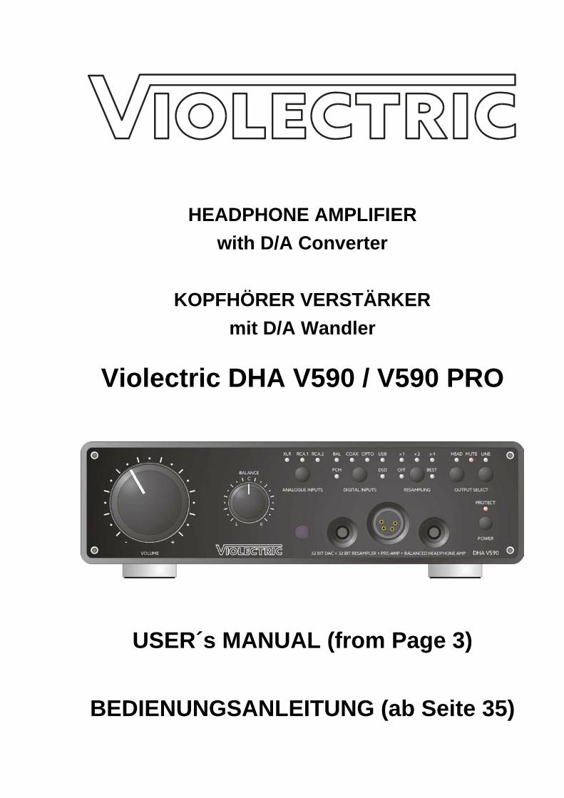
HEADPHONE AMPLIFIER with D/A Converter
KOPFHÖRER VERSTÄRKER
mit D/A Wandler
Violectric DHA V590 / V590 PRO
USER´s MANUAL (from Page 3)
BEDIENUNGSANLEITUNG (ab Seite 35)

2
3
Content
Theme Page
About 4 Safety Instructions 5 The Earth / Grounding Concept 6 Connection / Connectors 8 General 10 Remote Control 12 Block Circuitry 13 Operation 14 About Resampling 16 About PRE-GAIN 18 Reset 22 Software 23 Filter curves 24 Things to know 25 Disposal 28 Technical Data 28 Dismantling 30 Jumper Settings 31 Conformity Statement 32 Warranty 33
CAUTION!!
THE HIGH OUTPUT LEVELS ACHIEVABLE WITH THIS UNIT MAY
DAMAGE YOUR HEARING OR THE HEADPHONES IF OPERATED CARELESSLY!!
4
Cordial thanks for your decision in favour of a product!
is a trademark and product line of Lake People electronic GmbH. Lake People electronic GmbH develops, manufactures and distributes products in the professional range, for broadcast, television, airports, exhibition halls, festival venues, theatres, large-scale installations, private studios and more. In the private sector as well, Lake People products become increasingly popular due to their outstanding quality. The trademark and product line is specially intended to supply the Hi-Fi and High-End market with its specific requirements.
Who develops equipment? The devices are exclusively developed in Germany by the engineers of Lake People electronic GmbH. In doing so, the team of developers can draw on over thirty years of experience and countless products for the pro-audio domain. Among others, the first German-made 20-Bit A/D and D/A converters were developed by Lake People in the early nineties of the past century.
Who manufactures equipment? The devices are exclusively manufactured in Germany by Lake People electronic GmbH or contractors in the company's vicinity.
- put high emphasis on domestic manufacturing. Lake People - and by association As well, all component suppliers are chosen in order to achieve the main part of added value inland. How do devices get to the customer? The devices can be obtained from respective specialist suppliers. If there is none such accessible regionally, the customer is supported by transregional distribution partners (google may help...) and, of course, by on-line shop.
… and if it doesn't work like it should? devices are covered by a 5-years warranty. In case of any malfunction during this
period, they can be shipped to the manufacturer directly. Of course, the client will benefit from the full technical support even when warranty has expired. Any technical questions or need for advice is welcome.
is a subsidiary of
LAKE PEOPLE electronic GmbH
Turmstrasse 7a D-78467 Konstanz
Fon +49 (0) 7531 73678 Fax +49 (0) 7531 74998
www.lake-people.de www.lake-people.com
www.NIIMBUS-audio.de www.NIIMBUS-audio.com
www.violectric.de www.violectric.com
5
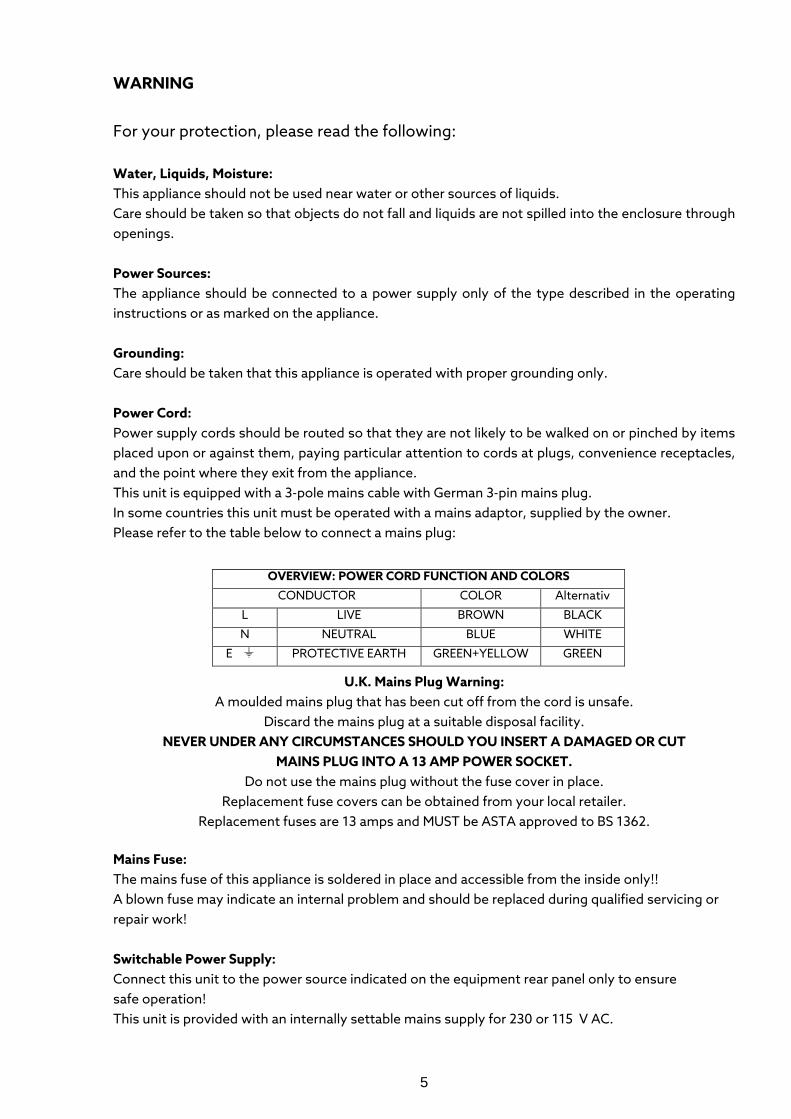
WARNING For your protection, please read the following: Water, Liquids, Moisture: This appliance should not be used near water or other sources of liquids. Care should be taken so that objects do not fall and liquids are not spilled into the enclosure through openings. Power Sources: The appliance should be connected to a power supply only of the type described in the operating instructions or as marked on the appliance. Grounding: Care should be taken that this appliance is operated with proper grounding only. Power Cord: Power supply cords should be routed so that they are not likely to be walked on or pinched by items placed upon or against them, paying particular attention to cords at plugs, convenience receptacles, and the point where they exit from the appliance. This unit is equipped with a 3-pole mains cable with German 3-pin mains plug. In some countries this unit must be operated with a mains adaptor, supplied by the owner. Please refer to the table below to connect a mains plug:
U.K. Mains Plug Warning: A moulded mains plug that has been cut off from the cord is unsafe.
Discard the mains plug at a suitable disposal facility. NEVER UNDER ANY CIRCUMSTANCES SHOULD YOU INSERT A DAMAGED OR CUT
MAINS PLUG INTO A 13 AMP POWER SOCKET. Do not use the mains plug without the fuse cover in place.
Replacement fuse covers can be obtained from your local retailer. Replacement fuses are 13 amps and MUST be ASTA approved to BS 1362.
Mains Fuse: The mains fuse of this appliance is soldered in place and accessible from the inside only!! A blown fuse may indicate an internal problem and should be replaced during qualified servicing or repair work! Switchable Power Supply: Connect this unit to the power source indicated on the equipment rear panel only to ensure safe operation! This unit is provided with an internally settable mains supply for 230 or 115 V AC.
OVERVIEW: POWER CORD FUNCTION AND COLORS CONDUCTOR COLOR Alternativ
L LIVE BROWN BLACK N NEUTRAL BLUE WHITE
E PROTECTIVE EARTH GREEN+YELLOW GREEN
6
Service / Repair: To reduce the risk of fire or electric shock, the user should not attempt to service the appliance beyond the measures described in the operating manual. All other servicing or repair should be referred to qualified personnel!
Electromagnetic Compatibility This unit conforms to the Product Specifications noted as Declaration of Conformity at the end of this manual. Operation is subject to the following conditions: - this device may not cause harmful interferences - this device must accept any interference received, including interference that may cause undesired operation - this device must not be operated within significant electromagnetic field
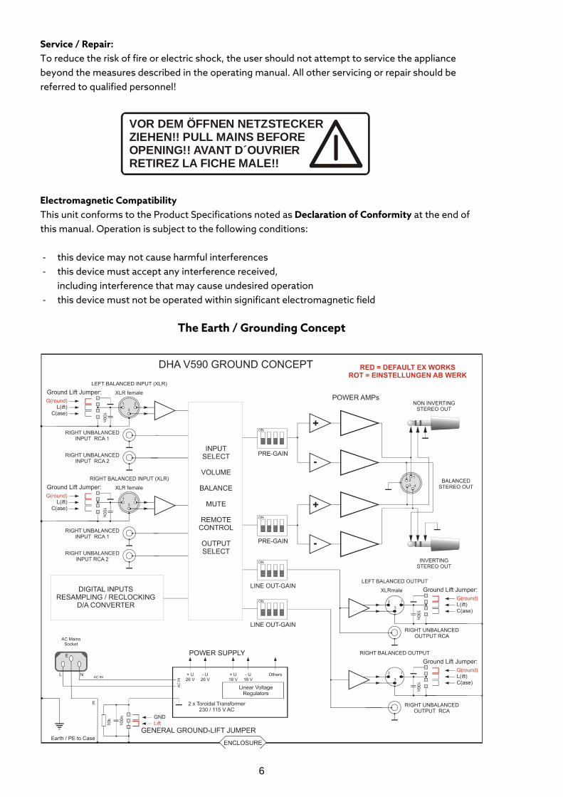
The Earth / Grounding Concept
VOR DEM ÖFFNEN NETZSTECKERZIEHEN!! PULL MAINS BEFOREOPENING!! AVANT D´OUVRIERRETIREZ LA FICHE MALE!!
7
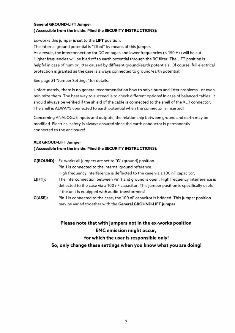
General GROUND-LIFT Jumper ( Accessible from the inside. Mind the SECURITY INSTRUCTIONS):
Ex-works this jumper is set to the LIFT position. The internal ground potential is “lifted” by means of this jumper. As a result, the interconnection for DC voltages and lower frequencies (< 150 Hz) will be cut. Higher frequencies will be bled off to earth potential through the RC filter. The LIFT position is helpful in case of hum or jitter caused by different ground/earth potentials. Of course, full electrical protection is granted as the case is always connected to ground/earth potential!
See page 31 "Jumper Settings" for details.
Unfortunately, there is no general recommendation how to solve hum and jitter problems - or even minimize them. The best way to succeed is to check different options! In case of balanced cables, it should always be verified if the shield of the cable is connected to the shell of the XLR connector. The shell is ALWAYS connected to earth potential when the connector is inserted!
Concerning ANALOGUE inputs and outputs, the relationship between ground and earth may be modified. Electrical safety is always ensured since the earth conductor is permanently connected to the enclosure! XLR GROUD-LIFT Jumper ( Accessible from the inside. Mind the SECURITY INSTRUCTIONS): G(ROUND): Ex-works all jumpers are set to "G" (ground) position.
Pin 1 is connected to the internal ground reference. High frequency interference is deflected to the case via a 100 nF capacitor.
L(IFT): The interconnection between Pin 1 and ground is open. High frequency interference is deflected to the case via a 100 nF capacitor. This jumper position is specifically useful if the unit is equipped with audio-transformers!
C(ASE): Pin 1 is connected to the case, the 100 nF capacitor is bridged. This jumper position may be varied together with the General GROUND-LIFT jumper.
Please note that with jumpers not in the ex-works position EMC emission might occur,
for which the user is responsible only! So, only change these settings when you know what you are doing!
8
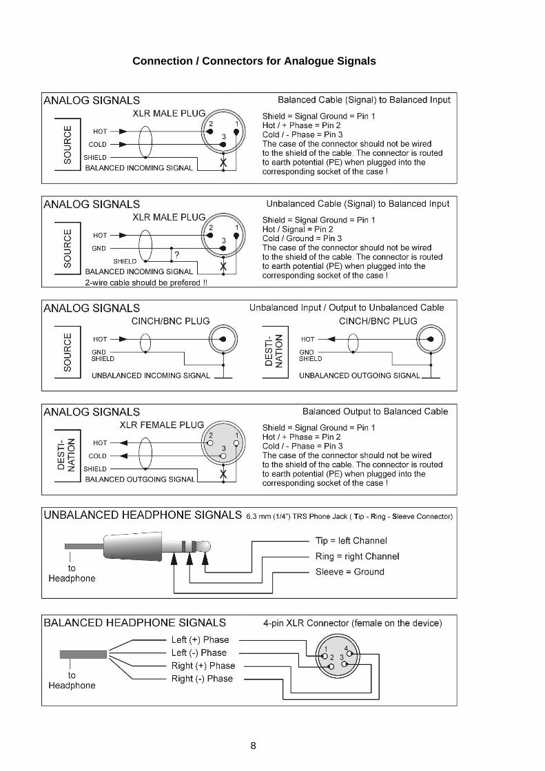
Connection / Connectors for Analogue Signals
9
10
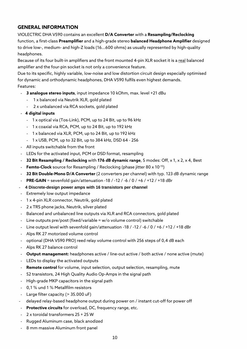
GENERAL INFORMATION VIOLECTRIC DHA V590 contains an excellent D/A Converter with a Resampling/Reclocking function, a first-class Preamplifier and a high-grade stereo balanced Headphone Amplifier designed to drive low-, medium- and high-Z loads (16...600 ohms) as usually represented by high-quality headphones. Because of its four built-in amplifiers and the front mounted 4-pin XLR socket it is a real balanced amplifier and the four-pin socket is not only a convenience feature. Due to its specific, highly variable, low-noise and low distortion circuit design especially optimised for dynamic and orthodynamic headphones, DHA V590 fulfils even highest demands. Features:
- 3 analogue stereo inputs, input impedance 10 kOhm, max. level +21 dBu
- 1 x balanced via Neutrik XLR, gold plated
- 2 x unbalanced via RCA sockets, gold plated
- 4 digital inputs
- 1 x optical via (Tos-Link), PCM, up to 24 Bit, up to 96 kHz
- 1 x coaxial via RCA, PCM, up to 24 Bit, up to 192 kHz
- 1 x balanced via XLR, PCM, up to 24 Bit, up to 192 kHz
- 1 x USB, PCM, up to 32 Bit, up to 384 kHz, DSD 64 - 256
- All inputs switchable from the front
- LEDs for the activated input, PCM or DSD format, resampling
- 32 Bit Resampling / Reclocking with 176 dB dynamic range, 5 modes: Off, x 1, x 2, x 4, Best
- Femto-Clock source for Resampling / Reclocking (phase jitter 80 x 10-15)
- 32 Bit Double-Mono D/A Converter (2 converters per channel) with typ. 123 dB dynamic range
- PRE-GAIN = sevenfold gain/attenuation -18 / -12 / -6 / 0 / +6 / +12 / +18 dBr
- 4 Discrete-design power amps with 16 transistors per channel - Extremely low output impedance
- 1 x 4-pin XLR connector, Neutrik, gold plated
- 2 x TRS phone jacks, Neutrik, silver plated
- Balanced and unbalanced line outputs via XLR and RCA connectors, gold plated
- Line outputs pre/post (fixed/variable = w/o volume control) switchable
- Line output level with sevenfold gain/attenuation -18 / -12 / -6 / 0 / +6 / +12 / +18 dBr
- Alps RK 27 motorized volume control
- optional (DHA V590 PRO) reed relay volume control with 256 steps of 0,4 dB each
- Alps RK 27 balance control
- Output management: headphones active / line-out active / both active / none active (mute)
- LEDs to display the activated outputs
- Remote control for volume, input selection, output selection, resampling, mute
- 52 transistors, 24 High Quality Audio Op-Amps in the signal path
- High-grade MKP capacitors in the signal path
- 0,1 % und 1 % Metallfilm resistors
- Large filter capacity (> 35.000 uF)
- delayed relay-based headphone output during power on / instant cut-off for power off
- Protective circuits for overload, DC, frequency range, etc.
- 2 x toroidal transformers 25 + 25 W
- Rugged Aluminum case, black anodized
- 8 mm massive Aluminum front panel

11
With its dimensions, the VIOLECTRIC DHA V590 ensures optimum flexibility combined with high output power. During design, high emphasis was put on operational safety even when the unit is operated inappropriately. DHA V590 is equipped with safety circuitry and internal filters to prevent damage to the connected headphones due to DC voltages at the outputs, power overload and high-frequency overload beyond the audible range.
THE CASE of VIOLECTRIC DHA V590 is made of 3 + 4 mm Aluminum and a thick 8 mm aluminum front panel. This choice of material ensures high mechanical stability and resistance whilst maintaining a high optical and haptic quality.
GROUND AND PROTECTIVE EARTH The case of VIOLECTRIC DHA V590 is connected to protective earth.
POWER SUPPLY Mains power is provided via a three-pin IEC/CEE socket and mating "cold-appliance" mains cord with Schuko-type plug for units purchased in middle Europe. The device is set to 230V mains, whereas the actual voltage may vary between 190 and 240 volts for flawless operation. The mains voltage may be altered to 115 V AC supply inside the unit with the aid of a mains voltage selector. In this case stable operation is granted in a range of 85 to 120 V (see page 31). Two toroidal transformers each with 25 Watt are providing the internal operating voltages of +/-25 V. Out of these voltages some more operating voltages are generated.
MAINS FUSE The time-lag fuse is soldered in place on the circuit board. In case, it must be replaced with a fuse of the same type only.
CAUTION!!
MIND THE SAFETY INSTRUCTIONS: A blown fuse indicates an internal fault and
should be replaced during qualified repair or servicing only!
12
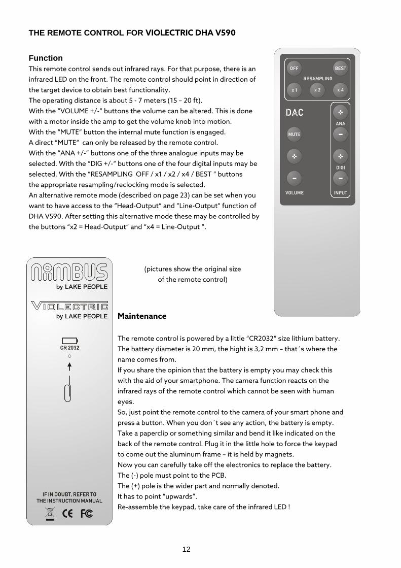
THE REMOTE CONTROL FOR VIOLECTRIC DHA V590
Function This remote control sends out infrared rays. For that purpose, there is an infrared LED on the front. The remote control should point in direction of the target device to obtain best functionality. The operating distance is about 5 - 7 meters (15 – 20 ft). With the “VOLUME +/-“ buttons the volume can be altered. This is done with a motor inside the amp to get the volume knob into motion. With the “MUTE“ button the internal mute function is engaged. A direct “MUTE“ can only be released by the remote control. With the “ANA +/-“ buttons one of the three analogue inputs may be selected. With the “DIG +/-“ buttons one of the four digital inputs may be selected. With the “RESAMPLING OFF / x1 / x2 / x4 / BEST “ buttons the appropriate resampling/reclocking mode is selected. An alternative remote mode (described on page 23) can be set when you want to have access to the “Head-Output“ and “Line-Output“ function of DHA V590. After setting this alternative mode these may be controlled by the buttons “x2 = Head-Output“ and “x4 = Line-Output “.
(pictures show the original size
of the remote control) Maintenance
The remote control is powered by a little “CR2032“ size lithium battery. The battery diameter is 20 mm, the hight is 3,2 mm – that´s where the name comes from. If you share the opinion that the battery is empty you may check this with the aid of your smartphone. The camera function reacts on the infrared rays of the remote control which cannot be seen with human eyes. So, just point the remote control to the camera of your smart phone and press a button. When you don´t see any action, the battery is empty. Take a paperclip or something similar and bend it like indicated on the back of the remote control. Plug it in the little hole to force the keypad to come out the aluminum frame – it is held by magnets. Now you can carefully take off the electronics to replace the battery. The (-) pole must point to the PCB. The (+) pole is the wider part and normally denoted. It has to point “upwards”. Re-assemble the keypad, take care of the infrared LED !
13
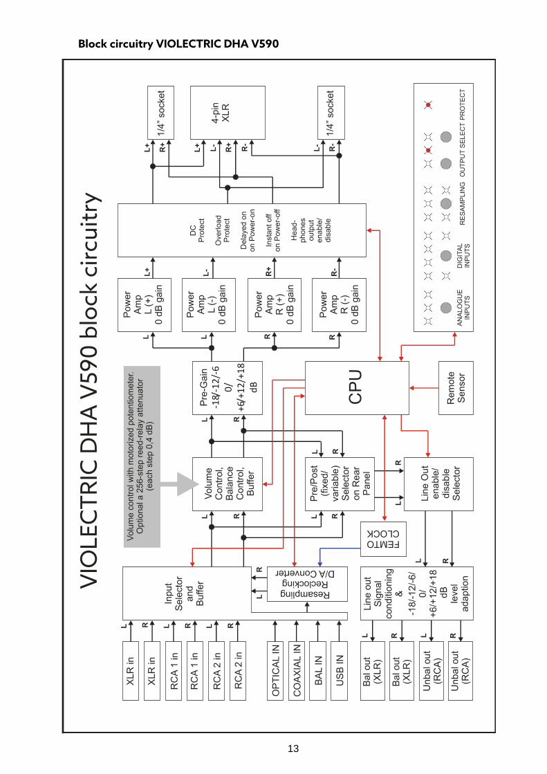
Block circuitry VIOLECTRIC DHA V590
14
THE POWER-SWITCH
The unit is put into operation by means of the power switch. The power-on procedure takes about 5 seconds. During this time the “PROTECT” LED flashes red until all internal parameter are checked and found OK. Any breakdown will cause the “PROTECT” LED to come up and the outputs are muted. DHA V590 will always start with the last settings of the input-, output- and resampling configuration.
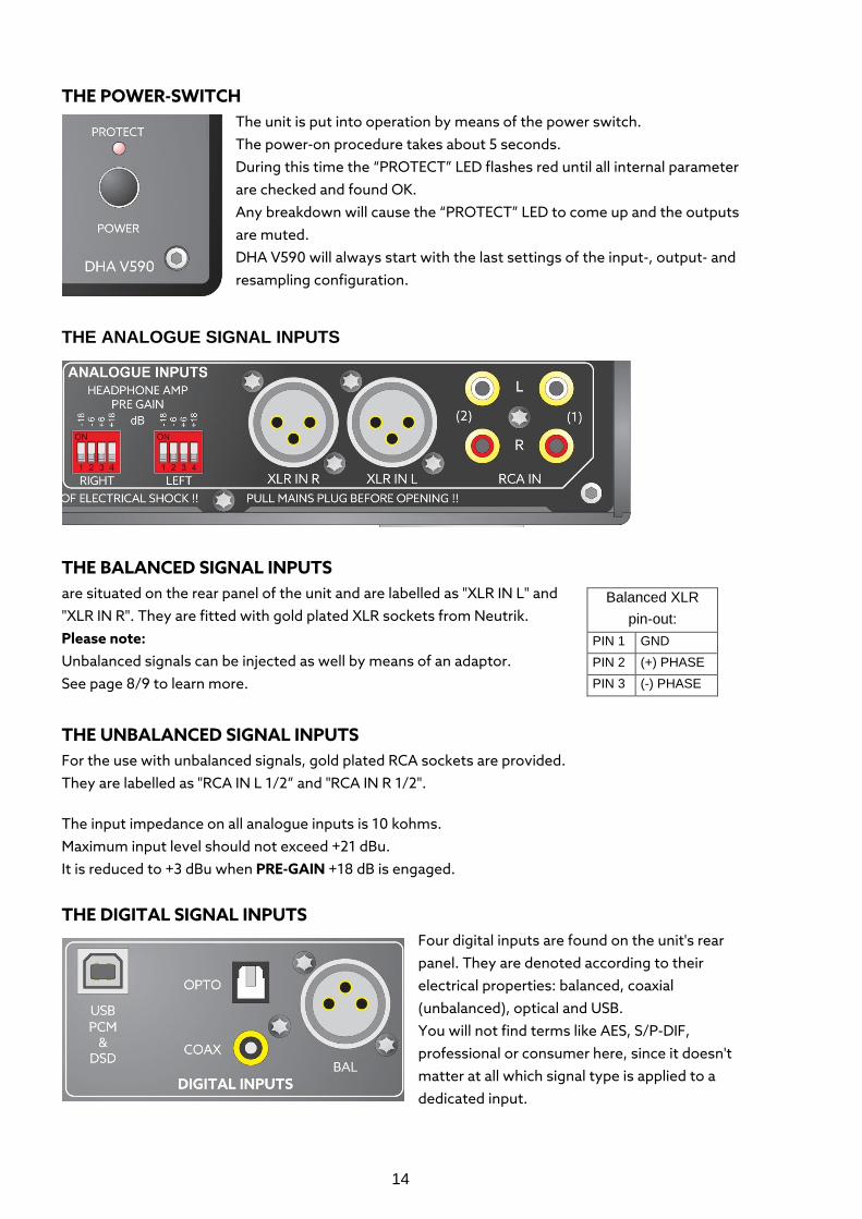
THE ANALOGUE SIGNAL INPUTS
THE BALANCED SIGNAL INPUTS are situated on the rear panel of the unit and are labelled as "XLR IN L" and "XLR IN R". They are fitted with gold plated XLR sockets from Neutrik. Please note: Unbalanced signals can be injected as well by means of an adaptor. See page 8/9 to learn more.
THE UNBALANCED SIGNAL INPUTS For the use with unbalanced signals, gold plated RCA sockets are provided. They are labelled as "RCA IN L 1/2” and "RCA IN R 1/2".
The input impedance on all analogue inputs is 10 kohms. Maximum input level should not exceed +21 dBu. It is reduced to +3 dBu when PRE-GAIN +18 dB is engaged.
THE DIGITAL SIGNAL INPUTS
Four digital inputs are found on the unit's rear panel. They are denoted according to their electrical properties: balanced, coaxial (unbalanced), optical and USB. You will not find terms like AES, S/P-DIF, professional or consumer here, since it doesn't matter at all which signal type is applied to a dedicated input.
Balanced XLR pin-out:
PIN 1 GND PIN 2 (+) PHASE PIN 3 (-) PHASE
15
- The balanced input is equipped with an XLR socket according to AES 3-1992, transformer-balanced, at 110 ohms input impedance and 200mV sensitivity at Tnom/2. It accepts PCM Signals up to 24 Bit, up to 192 kHz.
- The coaxial input is fitted with a RCA socket according to IEC 958 and AES-3-id resp., unbalanced. It accepts PCM Signals up to 24 Bit, up to 192 kHz. - The optical input provides a TOS-Link connector according to EIAJ RC-5720.
It accepts PCM Signals up to 24 Bit, up to 96 kHz. - The USB input is specified as an audio interface according to USB 2.0.
It accepts PCM Signals up to 32 Bit, up to 384 kHz and DSD Signals 64 - 256 The USB input is not in need of any drivers for Apple, Linux and Android units. For Windows 7 to Windows 10 full performance is achieved with drivers available here:
https://amanero.com/drivers.htm
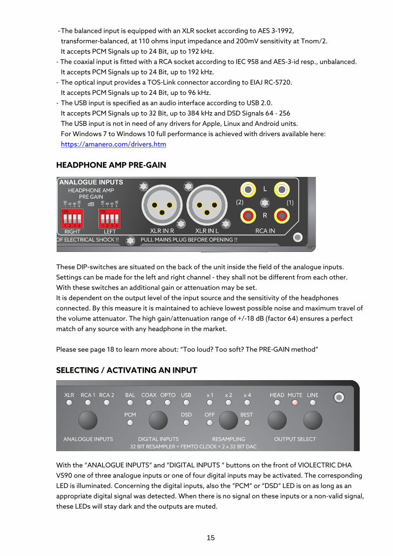
HEADPHONE AMP PRE-GAIN
These DIP-switches are situated on the back of the unit inside the field of the analogue inputs. Settings can be made for the left and right channel - they shall not be different from each other. With these switches an additional gain or attenuation may be set. It is dependent on the output level of the input source and the sensitivity of the headphones connected. By this measure it is maintained to achieve lowest possible noise and maximum travel of the volume attenuator. The high gain/attenuation range of +/-18 dB (factor 64) ensures a perfect match of any source with any headphone in the market. Please see page 18 to learn more about: “Too loud? Too soft? The PRE-GAIN method” SELECTING / ACTIVATING AN INPUT
With the “ANALOGUE INPUTS“ and “DIGITAL INPUTS “ buttons on the front of VIOLECTRIC DHA V590 one of three analogue inputs or one of four digital inputs may be activated. The corresponding LED is illuminated. Concerning the digital inputs, also the “PCM“ or “DSD“ LED is on as long as an appropriate digital signal was detected. When there is no signal on these inputs or a non-valid signal, these LEDs will stay dark and the outputs are muted.
16
You can also use the remote control for this purpose. Press the “ANA +/-“ buttons to change the analogue inputs. Press the “DIG +/-“ buttons to change the digital inputs.
RESAMPLING is a mighty feature for the transformation/restoration of jittered signals into high-quality signals. As well, the signal quality of 44.1 or 48 kHz sources can be improved by converting them to a higher rate. This also complies to the optical signals suffering from poor cables and USB signals which often suffer from jitter caused by improper treated computer outputs. With the aid of the resampling process nearly all jitter (and not only specific ones) is removed from the USB data stream without using “asynchronous USB mode” which is nonetheless also a feature of the USB input. This isn´t mystery at all, but a feature offered by so-called sample-rate converters - available since the nineties of the past century. While early sample rate converters with 20 Bit could provide conversion ratios of 1:2 to 2:1 (e.g. 44.1 to 88.2 kHz Sample-Rate) at 100dB dynamic range only, ratios of 1:48 to 48:1 (44.1 to 176.4 kHz = 1 : 4) with 32 Bit at nearly 180 dB dynamic range are feasible today. In principle, the digital data stream is asynchronously disassembled by a DSP specially developed for this purpose - and can be recombined at virtually any sample rate desired. The quality of this recombination is directly dependent from the SRC´s clock source. Therefore, inside DHA V590 a special low jitter oscillator is installed, the FEMTO-CLOCK, featuring a phase jitter as low as 80 fs = Femtoseconds = 80x10-15. The oscillator is powered by a low noise source made of discrete components. By means of this process, all potential jitter vanishes almost completely and - due to the higher sampling rate - the analogue filters after the converter stage can follow a much more straightforward and "musical" design. Furthermore, all digital input signals will be completed to 32 Bit.
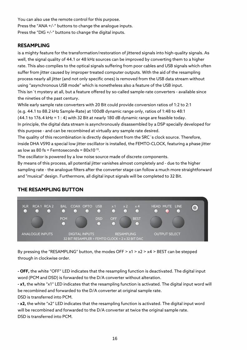
THE RESAMPLING BUTTON
By pressing the “RESAMPLING“ button, the modes OFF > x1 > x2 > x4 > BEST can be stepped through in clockwise order. - OFF, the white “OFF“ LED indicates that the resampling function is deactivated. The digital input word (PCM and DSD) is forwarded to the D/A converter without alteration. - x1, the white “x1“ LED indicates that the resampling function is activated. The digital input word will be recombined and forwarded to the D/A converter at original sample rate. DSD is transferred into PCM. - x2, the white “x2“ LED indicates that the resampling function is activated. The digital input word will be recombined and forwarded to the D/A converter at twice the original sample rate. DSD is transferred into PCM.
17
- x4, the white "x4" LED indicates that the resampling function is activated. The digital input word will be recombined and forwarded to the D/A converter at four times the original sample rate. DSD is transferred into PCM. - BEST, the white “BEST“ LED indicates that the resampling function is activated. The digital input word will be recombined and forwarded to the D/A converter at a sample rate of 96 kHz, a rate at which most contemporary converters perform best. DSD is transferred into PCM. The remote control enables a direct access to the above modes.
THE DIGITAL to ANALOGUE CONVERTERS comprises the adjustable digital filters (see software menu 2 on page 23), the D/A converters as such, as well as the analogue output filters. The converters are based on a delta-sigma architecture and provide a dynamic range of 123 dB and THD+N -112 dB. According to the double-mono architecture two 32 Bit D/A converters per channel are used inside DHA V590 to achieve higher linearity and lower noise. An incoming 16, 20 or 24 Bit signal is expanded in a 32 Bit signal inside the converters as long as it was not completed by the resampling circuitry before. The internal frequency of the digital signal (and potential interference therein) is very high in comparison with the useful analogue frequencies. Therefore, the subsequent analogue low-pass filters have to meet less severe requirements in terms of high-frequency roll-off and can therefore be realized as "musical", discrete two-pole filters.
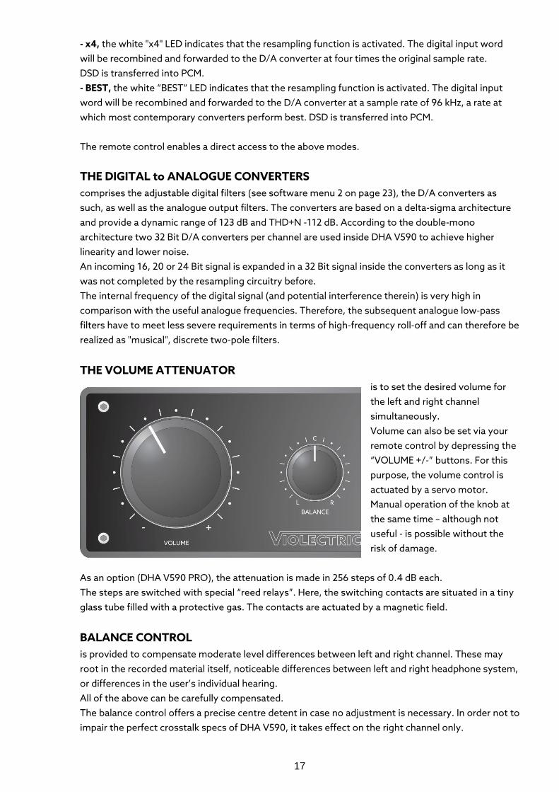
THE VOLUME ATTENUATOR is to set the desired volume for the left and right channel simultaneously. Volume can also be set via your remote control by depressing the “VOLUME +/-” buttons. For this purpose, the volume control is actuated by a servo motor. Manual operation of the knob at the same time – although not useful - is possible without the risk of damage.
As an option (DHA V590 PRO), the attenuation is made in 256 steps of 0.4 dB each. The steps are switched with special “reed relays”. Here, the switching contacts are situated in a tiny glass tube filled with a protective gas. The contacts are actuated by a magnetic field.
BALANCE CONTROL is provided to compensate moderate level differences between left and right channel. These may root in the recorded material itself, noticeable differences between left and right headphone system, or differences in the user’s individual hearing. All of the above can be carefully compensated. The balance control offers a precise centre detent in case no adjustment is necessary. In order not to impair the perfect crosstalk specs of DHA V590, it takes effect on the right channel only.
18
Too loud? Too soft? The PRE-GAIN method The VIOLECTRIC DHA V590 is specially designed to drive headphones. To do so it is placed between up to three analogue or up to four digital sources and the headphones. Headphones however can present load impedances from 8 to 2000 ohms and efficiency ratios from 85 to 115 dB per Milliwatt. The sources may have output levels between 0.5 Volt up to 10 Volt. Thus, it can be quite tricky to fulfil all demands, since... … owners of high-efficiency headphones will rarely set the volume control higher than 9 o'clock in order to exclude hearing damage, while ... the maximum setting may still be too soft for low-efficiency headphones, but … all users expect highest quality at lowest noise and distortion. Thus, the circuitry must adapt itself as the headphones will not do and the sources will seldom do!
WE CALL THE SOLUTION TO THIS PROBLEM PRE-GAIN
A single amp of DHA V590 has no gain (gain = 0 dB = factor 1). In case a balanced headphone is connected two amps are active with a combined gain of +6 dB (factor 2). By this measure the amps will produce an extremely low self-generated noise which can hardly been heard even with highest sensitive in-ear-monitors (IEM). On the other hand, the amps of DHA V590 with very powerful transformers and with their high operating voltage are able to drive low efficiency or high impedance headphone to the full with ease. You will be unable to find a headphone driving DHA V590 to its limits. This effortless action will save your precious headphones as they will never see a distorted signal from the amp. The alignment between amplifier and headphone is provided by the preamp stage, which can boost or attenuate the input signal in seven steps of -18 / -12 / -6 / 0 / +6 / +12 / +18 dBr. For this purpose, two switching devices are located on the rear panel for left and right channel individually.
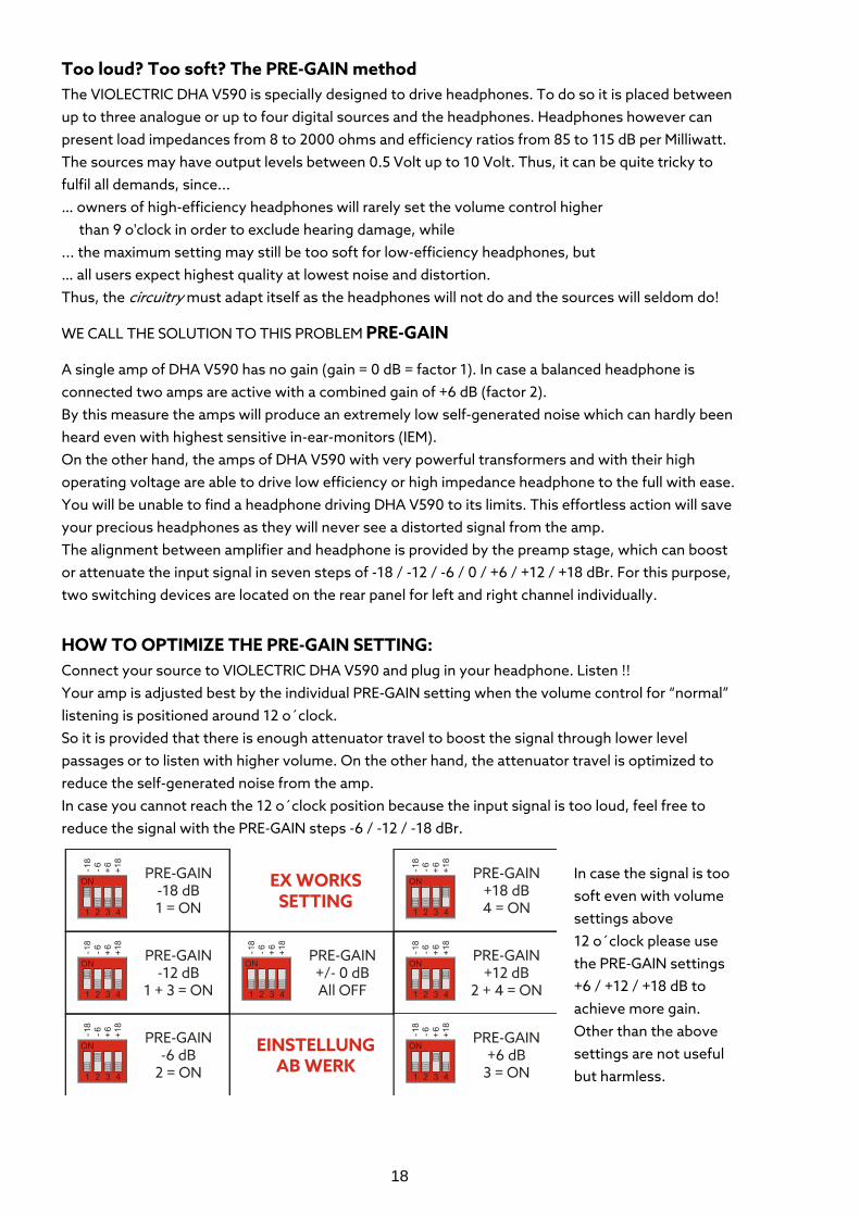
HOW TO OPTIMIZE THE PRE-GAIN SETTING: Connect your source to VIOLECTRIC DHA V590 and plug in your headphone. Listen !! Your amp is adjusted best by the individual PRE-GAIN setting when the volume control for “normal” listening is positioned around 12 o´clock. So it is provided that there is enough attenuator travel to boost the signal through lower level passages or to listen with higher volume. On the other hand, the attenuator travel is optimized to reduce the self-generated noise from the amp. In case you cannot reach the 12 o´clock position because the input signal is too loud, feel free to reduce the signal with the PRE-GAIN steps -6 / -12 / -18 dBr.
In case the signal is too soft even with volume settings above 12 o´clock please use the PRE-GAIN settings +6 / +12 / +18 dB to achieve more gain. Other than the above settings are not useful but harmless.
19
CAUTION To avoid unwanted level leaps the settings should be altered under the following conditions only:
- the "VOLUME" control should be set to minimum or the headphone outputs shall be deactivated using the “HEAD“ button
- left and right channel settings should be the same unless you want to settle the amp for different hearing abilities
Ex-factory, all switches are set to their lowest position - i.e. 0 dB PRE-GAIN - which should be sufficient for most applications.
THE AMPLIFIER(S) The input signals are fed to an amplifier stage especially designed for this application, with 2 x eight transistors per channel. Because of the true balanced operation VIOLECTRIC DHA V590 houses no less than four of those! All in all, 32 of over 52 transistors of the unit are responsible to process analogue signals. The channels are physically separated from each other to ensure optimum crosstalk rejection. The frequency range covers 5 Hz ... 250 kHz (-0.5 dB) in order to ensure fully linear performance within the entire audible range. Overall gain is set to 0 dB (unbalanced) or +6 dB respectively (balanced) to ensure lowest self-generated noise.
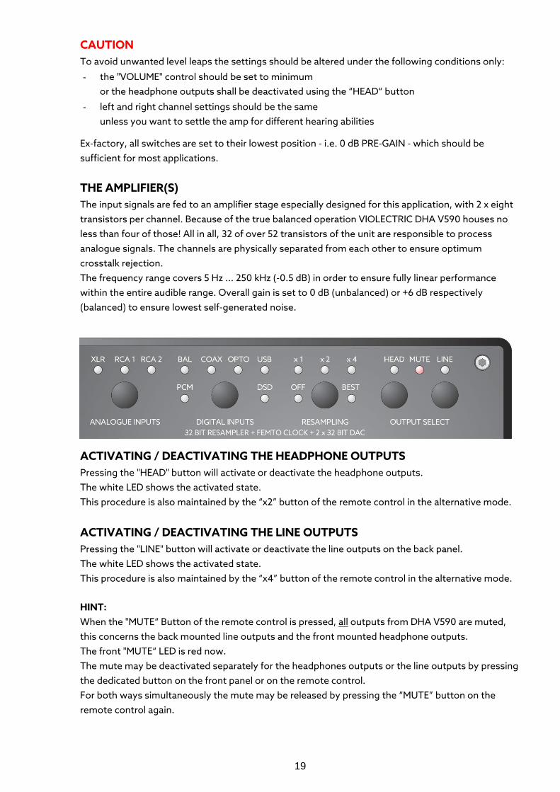
ACTIVATING / DEACTIVATING THE HEADPHONE OUTPUTS Pressing the "HEAD" button will activate or deactivate the headphone outputs. The white LED shows the activated state. This procedure is also maintained by the “x2” button of the remote control in the alternative mode.
ACTIVATING / DEACTIVATING THE LINE OUTPUTS Pressing the "LINE" button will activate or deactivate the line outputs on the back panel. The white LED shows the activated state. This procedure is also maintained by the “x4” button of the remote control in the alternative mode.
HINT: When the "MUTE“ Button of the remote control is pressed, all outputs from DHA V590 are muted, this concerns the back mounted line outputs and the front mounted headphone outputs. The front "MUTE“ LED is red now. The mute may be deactivated separately for the headphones outputs or the line outputs by pressing the dedicated button on the front panel or on the remote control. For both ways simultaneously the mute may be released by pressing the “MUTE” button on the remote control again.
20
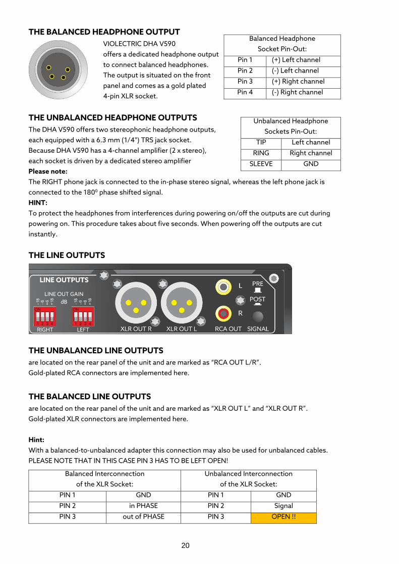
THE BALANCED HEADPHONE OUTPUT VIOLECTRIC DHA V590 offers a dedicated headphone output to connect balanced headphones. The output is situated on the front panel and comes as a gold plated 4-pin XLR socket.
THE UNBALANCED HEADPHONE OUTPUTS The DHA V590 offers two stereophonic headphone outputs, each equipped with a 6.3 mm (1/4") TRS jack socket. Because DHA V590 has a 4-channel amplifier (2 x stereo), each socket is driven by a dedicated stereo amplifier Please note: The RIGHT phone jack is connected to the in-phase stereo signal, whereas the left phone jack is connected to the 1800 phase shifted signal. HINT: To protect the headphones from interferences during powering on/off the outputs are cut during powering on. This procedure takes about five seconds. When powering off the outputs are cut instantly.
THE LINE OUTPUTS
THE UNBALANCED LINE OUTPUTS are located on the rear panel of the unit and are marked as “RCA OUT L/R”. Gold-plated RCA connectors are implemented here.
THE BALANCED LINE OUTPUTS are located on the rear panel of the unit and are marked as “XLR OUT L” and “XLR OUT R”. Gold-plated XLR connectors are implemented here. Hint: With a balanced-to-unbalanced adapter this connection may also be used for unbalanced cables. PLEASE NOTE THAT IN THIS CASE PIN 3 HAS TO BE LEFT OPEN!
Balanced Headphone Socket Pin-Out:
Pin 1 (+) Left channel
Pin 2 (-) Left channel
Pin 3 (+) Right channel
Pin 4 (-) Right channel
Unbalanced Headphone Sockets Pin-Out:
TIP Left channel
RING Right channel
SLEEVE GND
Balanced Interconnection of the XLR Socket:
Unbalanced Interconnection of the XLR Socket:
PIN 1 GND PIN 1 GND
PIN 2 in PHASE PIN 2 Signal
PIN 3 out of PHASE PIN 3 OPEN !!
21
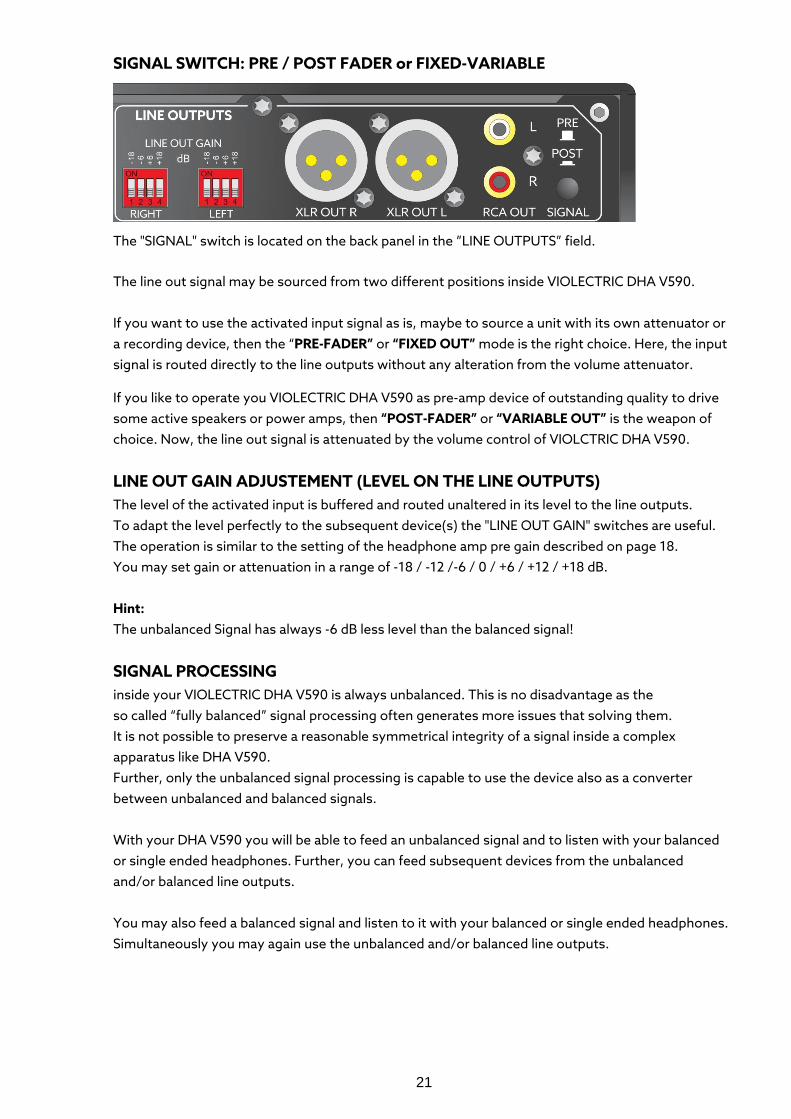
SIGNAL SWITCH: PRE / POST FADER or FIXED-VARIABLE
The "SIGNAL" switch is located on the back panel in the ”LINE OUTPUTS” field.
The line out signal may be sourced from two different positions inside VIOLECTRIC DHA V590. If you want to use the activated input signal as is, maybe to source a unit with its own attenuator or a recording device, then the “PRE-FADER” or “FIXED OUT” mode is the right choice. Here, the input signal is routed directly to the line outputs without any alteration from the volume attenuator.
If you like to operate you VIOLECTRIC DHA V590 as pre-amp device of outstanding quality to drive some active speakers or power amps, then “POST-FADER” or “VARIABLE OUT” is the weapon of choice. Now, the line out signal is attenuated by the volume control of VIOLCTRIC DHA V590.
LINE OUT GAIN ADJUSTEMENT (LEVEL ON THE LINE OUTPUTS) The level of the activated input is buffered and routed unaltered in its level to the line outputs. To adapt the level perfectly to the subsequent device(s) the "LINE OUT GAIN" switches are useful. The operation is similar to the setting of the headphone amp pre gain described on page 18. You may set gain or attenuation in a range of -18 / -12 /-6 / 0 / +6 / +12 / +18 dB. Hint: The unbalanced Signal has always -6 dB less level than the balanced signal!
SIGNAL PROCESSING inside your VIOLECTRIC DHA V590 is always unbalanced. This is no disadvantage as the so called “fully balanced” signal processing often generates more issues that solving them. It is not possible to preserve a reasonable symmetrical integrity of a signal inside a complex apparatus like DHA V590. Further, only the unbalanced signal processing is capable to use the device also as a converter between unbalanced and balanced signals. With your DHA V590 you will be able to feed an unbalanced signal and to listen with your balanced or single ended headphones. Further, you can feed subsequent devices from the unbalanced and/or balanced line outputs. You may also feed a balanced signal and listen to it with your balanced or single ended headphones. Simultaneously you may again use the unbalanced and/or balanced line outputs.
22
ERROR REPORTING:
To ensure error-free operation and not to harm your valuable headphones in a comprehensive way your VIOLECTRIC DHA V590 is equipped with a number of protective circuits:
- During powering on there is a five seconds delay to protect your headphones from possibly unwholesome noises. After the time the headphone outputs are switched to the amp. Also, the instant cut-off after powering off is intended to protect your headphones.
- DC voltages are no good part of the output signal and must be avoided. If such are detected, the headphone sockets are cut from the electronics and the ”PROTECT” LED is switched to red. When the DC voltage has vanished, the amp will automatically return to “normal” operation.
- Overload causes distorted output signals and is also harmful for the headphones. If an overload was detected, the headphone sockets are cut from the electronics and the ”PROTECT” LED is switched to red. When the overload disappeared, the amp will automatically return to “normal” operation.
- All errors will also reset when the unit is switched off and on again. In case that there is still an error condition the protecting circuits will keep the error mode and the status LED is red.
RESET OF THE PROCESSORS Many internal procedures are enabled by processors.
If - of any reasons - nothing seems to work as it should anymore, follow these instructions to come back to DEFAULT SETTINGS: Push and hold the “ANALOGUE INPUT” button whilst powering the unit. Soon after all LEDs on the front panel will light up. Now you can release the “INPUT SELECT” button as all settings had been reset to default.
23
SOFTWARE Menu 1 – altering the remote control
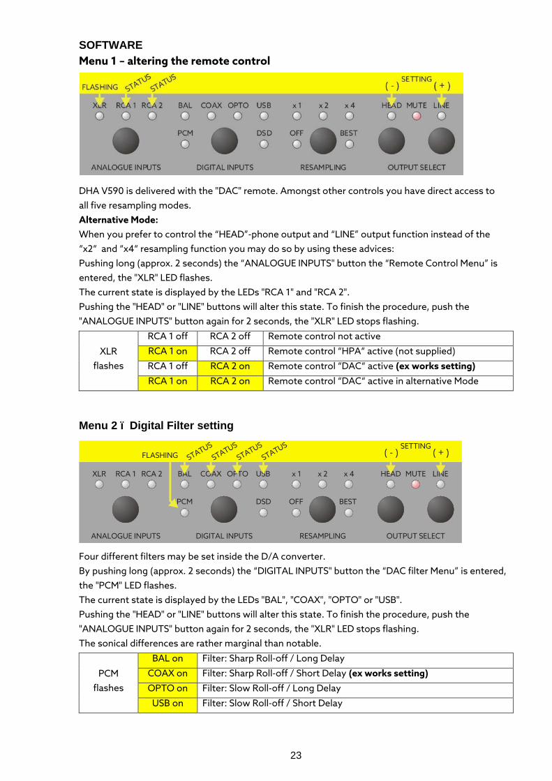
DHA V590 is delivered with the "DAC" remote. Amongst other controls you have direct access to all five resampling modes. Alternative Mode: When you prefer to control the “HEAD”-phone output and “LINE” output function instead of the “x2“ and “x4“ resampling function you may do so by using these advices: Pushing long (approx. 2 seconds) the “ANALOGUE INPUTS" button the “Remote Control Menu” is entered, the "XLR" LED flashes. The current state is displayed by the LEDs "RCA 1" and "RCA 2". Pushing the "HEAD" or "LINE" buttons will alter this state. To finish the procedure, push the "ANALOGUE INPUTS" button again for 2 seconds, the "XLR" LED stops flashing.
XLR flashes
RCA 1 off RCA 2 off Remote control not active
RCA 1 on RCA 2 off Remote control “HPA“ active (not supplied)
RCA 1 off RCA 2 on Remote control “DAC“ active (ex works setting)
RCA 1 on RCA 2 on Remote control “DAC“ active in alternative Mode
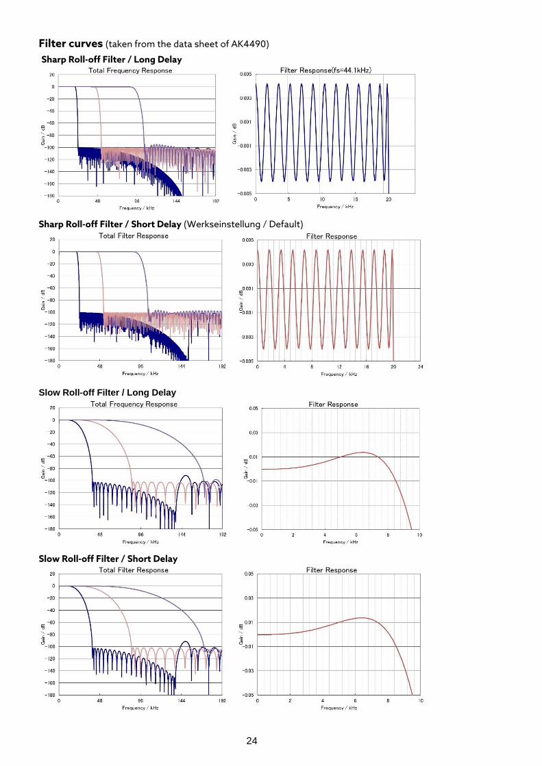
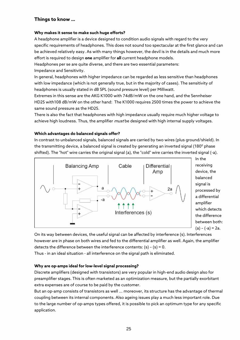
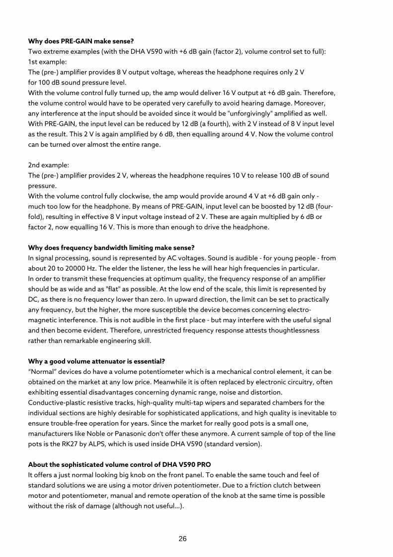
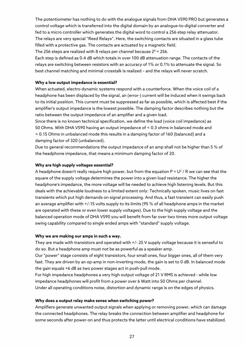
Menu 2 – Digital Filter setting
Four different filters may be set inside the D/A converter. By pushing long (approx. 2 seconds) the “DIGITAL INPUTS" button the “DAC filter Menu” is entered, the "PCM" LED flashes. The current state is displayed by the LEDs "BAL", "COAX", "OPTO" or "USB". Pushing the "HEAD" or "LINE" buttons will alter this state. To finish the procedure, push the "ANALOGUE INPUTS" button again for 2 seconds, the "XLR" LED stops flashing. The sonical differences are rather marginal than notable.
PCM flashes
BAL on Filter: Sharp Roll-off / Long Delay
COAX on Filter: Sharp Roll-off / Short Delay (ex works setting)
OPTO on Filter: Slow Roll-off / Long Delay
USB on Filter: Slow Roll-off / Short Delay
24
Filter curves (taken from the data sheet of AK4490) Sharp Roll-off Filter / Long Delay
Sharp Roll-off Filter / Short Delay (Werkseinstellung / Default)
Slow Roll-off Filter / Long Delay Slow Roll-off Filter / Short Delay
25
Things to know …
Why makes it sense to make such huge efforts? A headphone amplifier is a device designed to condition audio signals with regard to the very specific requirements of headphones. This does not sound too spectacular at the first glance and can be achieved relatively easy. As with many things however, the devil is in the details and much more effort is required to design one amplifier for all current headphone models. Headphones per se are quite diverse, and there are two essential parameters: Impedance and Sensitivity. In general, headphones with higher impedance can be regarded as less sensitive than headphones with low impedance (which is not generally true, but in the majority of cases). The sensitivity of headphones is usually stated in dB SPL (sound pressure level) per Milliwatt. Extremes in this sense are the AKG K1000 with 74dB/mW on the one hand, and the Sennheiser HD25 with108 dB/mW on the other hand: The K1000 requires 2500 times the power to achieve the same sound pressure as the HD25. There is also the fact that headphones with high impedance usually require much higher voltage to achieve high loudness. Thus, the amplifier must be designed with high internal supply voltages. Which advantages do balanced signals offer? In contrast to unbalanced signals, balanced signals are carried by two wires (plus ground/shield). In the transmitting device, a balanced signal is created by generating an inverted signal (1800 phase shifted). The "hot" wire carries the original signal (a), the "cold" wire carries the inverted signal (-a).
In the receiving device, the balanced signal is processed by a differential amplifier which detects the difference between both: (a) – (-a) = 2a.
On its way between devices, the useful signal can be affected by interference (s). Interferences however are in phase on both wires and fed to the differential amplifier as well. Again, the amplifier detects the difference between the interference contents: (s) – (s) = 0. Thus - in an ideal situation - all interference on the signal path is eliminated. Why are op-amps ideal for low-level signal processing? Discrete amplifiers (designed with transistors) are very popular in high-end audio design also for preamplifier stages. This is often marketed as an optimization measure, but the partially exorbitant extra expenses are of course to be paid by the customer. But an op-amp consists of transistors as well ... moreover, its structure has the advantage of thermal coupling between its internal components. Also ageing issues play a much less important role. Due to the large number of op-amps types offered, it is possible to pick an optimum type for any specific application.
26
Why does PRE-GAIN make sense? Two extreme examples (with the DHA V590 with +6 dB gain (factor 2), volume control set to full): 1st example: The (pre-) amplifier provides 8 V output voltage, whereas the headphone requires only 2 V for 100 dB sound pressure level. With the volume control fully turned up, the amp would deliver 16 V output at +6 dB gain. Therefore, the volume control would have to be operated very carefully to avoid hearing damage. Moreover, any interference at the input should be avoided since it would be "unforgivingly" amplified as well. With PRE-GAIN, the input level can be reduced by 12 dB (a fourth), with 2 V instead of 8 V input level as the result. This 2 V is again amplified by 6 dB, then equalling around 4 V. Now the volume control can be turned over almost the entire range. 2nd example: The (pre-) amplifier provides 2 V, whereas the headphone requires 10 V to release 100 dB of sound pressure. With the volume control fully clockwise, the amp would provide around 4 V at +6 dB gain only - much too low for the headphone. By means of PRE-GAIN, input level can be boosted by 12 dB (four-fold), resulting in effective 8 V input voltage instead of 2 V. These are again multiplied by 6 dB or factor 2, now equalling 16 V. This is more than enough to drive the headphone. Why does frequency bandwidth limiting make sense? In signal processing, sound is represented by AC voltages. Sound is audible - for young people - from about 20 to 20000 Hz. The elder the listener, the less he will hear high frequencies in particular. In order to transmit these frequencies at optimum quality, the frequency response of an amplifier should be as wide and as "flat" as possible. At the low end of the scale, this limit is represented by DC, as there is no frequency lower than zero. In upward direction, the limit can be set to practically any frequency, but the higher, the more susceptible the device becomes concerning electro-magnetic interference. This is not audible in the first place - but may interfere with the useful signal and then become evident. Therefore, unrestricted frequency response attests thoughtlessness rather than remarkable engineering skill. Why a good volume attenuator is essential? “Normal” devices do have a volume potentiometer which is a mechanical control element, it can be obtained on the market at any low price. Meanwhile it is often replaced by electronic circuitry, often exhibiting essential disadvantages concerning dynamic range, noise and distortion. Conductive-plastic resistive tracks, high-quality multi-tap wipers and separated chambers for the individual sections are highly desirable for sophisticated applications, and high quality is inevitable to ensure trouble-free operation for years. Since the market for really good pots is a small one, manufacturers like Noble or Panasonic don't offer these anymore. A current sample of top of the line pots is the RK27 by ALPS, which is used inside DHA V590 (standard version). About the sophisticated volume control of DHA V590 PRO It offers a just normal looking big knob on the front panel. To enable the same touch and feel of standard solutions we are using a motor driven potentiometer. Due to a friction clutch between motor and potentiometer, manual and remote operation of the knob at the same time is possible without the risk of damage (although not useful…).
27
The potentiometer has nothing to do with the analogue signals from DHA V590 PRO but generates a control voltage which is transferred into the digital domain by an analogue-to-digital converter and fed to a micro controller which generates the digital word to control a 256 step relay attenuator. The relays are very special “Reed Relays”. Here, the switching contacts are situated in a glass tube filled with a protective gas. The contacts are actuated by a magnetic field. The 256 steps are realized with 8 relays per channel because 28 = 256. Each step is defined as 0.4 dB which totals in over 100 dB attenuation range. The contacts of the relays are switching between resistors with an accuracy of 1% or 0.1% to attenuate the signal. So best channel matching and minimal crosstalk is realized – and the relays will never scratch.
Why a low output impedance is essential? When actuated, electro-dynamic systems respond with a counterforce. When the voice coil of a headphone has been displaced by the signal, an (error-) current will be induced when it swings back to its initial position. This current must be suppressed as far as possible, which is affected best if the amplifier's output impedance is the lowest possible. The damping factor describes nothing but the ratio between the output impedance of an amplifier and a given load. Since there is no known technical specification, we define the load (voice coil impedance) as 50 Ohms. With DHA V590 having an output impedance of < 0.3 ohms in balanced mode and < 0.15 Ohms in unbalanced mode this results in a damping factor of 160 (balanced) and a damping factor of 320 (unbalanced). Due to general recommendations the output impedance of an amp shall not be higher than 5 % of the headphone impedance, that means a minimum damping factor of 20.
Why are high supply voltages essential? A headphone doesn't really require high power, but from the equation P = U2 / R we can see that the square of the supply voltage determines the power into a given load resistance. The higher the headphone's impedance, the more voltage will be needed to achieve high listening levels. But this deals with the achievable loudness to a limited extent only: Technically spoken, music lives on fast transients which put high demands on signal processing. And thus, a fast transient can easily push an average amplifier with +/-15 volts supply to its limits (95 % of all headphone amps in the market are operated with these or even lower supply voltages). Due to the high supply voltage and the balanced operation mode of DHA V590 you will benefit from far over two times more output voltage swing capability compared to single ended amps with “standard” supply voltage. Why we are making our amps in such a way. They are made with transistors and operated with +/- 25 V supply voltage because it is senseful to do so. But a headphone amp must not be as powerful as a speaker amp. Our “power“ stage consists of eight transistors, four small ones, four bigger ones, all of them very fast. They are driven by an op-amp in non-inverting mode, the gain is set to 0 dB. In balanced mode the gain equals +6 dB as two power stages act in push-pull mode. For high impedance headphones a very high output voltage of 21 V RMS is achieved - while low impedance headphones will profit from a power over 6 Watt into 50 Ohms per channel. Under all operating conditions noise, distortion and dynamic range is on the edges of physics. Why does a output relay make sense when switching power? Amplifiers generate unwanted output signals when applying or removing power, which can damage the connected headphones. The relay breaks the connection between amplifier and headphone for some seconds after power-on and thus protects the latter until electrical conditions have stabilized.
28
DISPOSAL
Disposal of Old Electrical & Electronic Equipment - WEEE Regulation (Applicable in the European Union and other European countries with separate collection systems)
This symbol on the product or on its packaging indicates that this product shall not be treated as household waste. Instead it shall be handed over to the applicable collection point for the recycling of electrical and electronic equipment. By ensuring this product is disposed of correctly, you will help prevent potential negative consequences for the environment and human health, which could otherwise be caused by inappropriate waste handling of this product. The recycling of materials will help to conserve natural resources.
For more detailed information about recycling of this product, please contact your local Civic Office, your household waste disposal service or the shop where you purchased the product.
TECHNICAL DATA VIOLECTRIC DHA V590 All measurements RMS unwtd., 20 Hz - 20 kHz, Pre-Gain set to 0 dB
Input Parameter Analogue Inputs (stereo, analogue): 1 x XLR female, balanced, 2 x RCA, unbalanced Max. Input Level: + 21 dBu Input Impedance: 10 kOhm Input Parameter Digital Inputs (stereo, digital) 1 x Balanced, XLR, PCM up to 24 Bit, 192 kHz 1 x Unbalanced, Coaxial, PCM up to 24 Bit, 192 kHz 1 x optical, Tos-Link, PCM up to 24 Bit, 96 kHz 1 x USB, PCM up to 32 Bit, 384 kHz / DSD 64 up to 256 Line Out Parameter Line Outputs (stereo, analogue): 1 x XLR male, balanced 1 x RCA unbalanced Line-Out Gain: -18 / -12 / -6 / 0 / +6 / +12 / +18 dBr Max. Output Voltage: + 21 dBu Output Impedance: < 1 Ohm
29
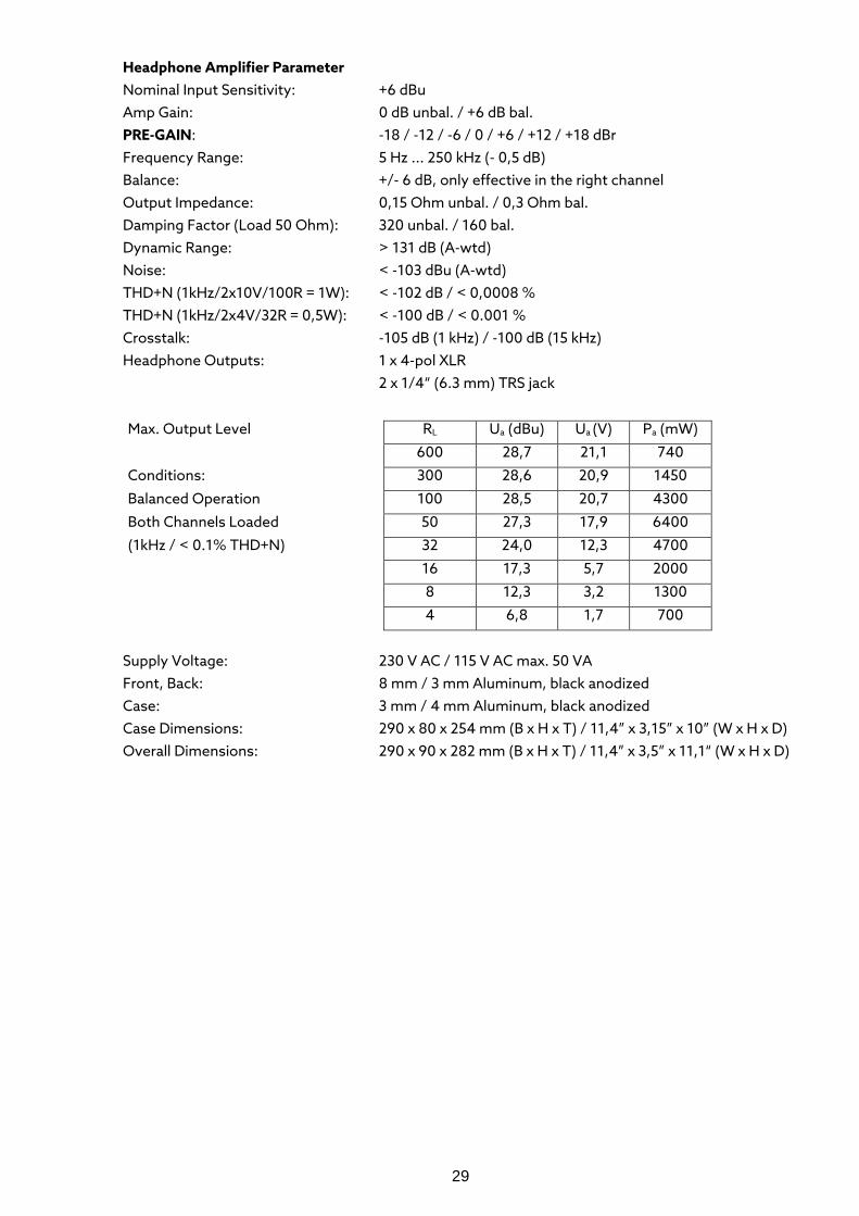
Headphone Amplifier Parameter Nominal Input Sensitivity: +6 dBu Amp Gain: 0 dB unbal. / +6 dB bal. PRE-GAIN: -18 / -12 / -6 / 0 / +6 / +12 / +18 dBr Frequency Range: 5 Hz ... 250 kHz (- 0,5 dB) Balance: +/- 6 dB, only effective in the right channel Output Impedance: 0,15 Ohm unbal. / 0,3 Ohm bal. Damping Factor (Load 50 Ohm): 320 unbal. / 160 bal. Dynamic Range: > 131 dB (A-wtd) Noise: < -103 dBu (A-wtd) THD+N (1kHz/2x10V/100R = 1W): < -102 dB / < 0,0008 % THD+N (1kHz/2x4V/32R = 0,5W): < -100 dB / < 0.001 % Crosstalk: -105 dB (1 kHz) / -100 dB (15 kHz) Headphone Outputs: 1 x 4-pol XLR 2 x 1/4“ (6.3 mm) TRS jack
Max. Output Level RL Ua (dBu) Ua (V) Pa (mW)
600 28,7 21,1 740
Conditions: 300 28,6 20,9 1450
Balanced Operation 100 28,5 20,7 4300
Both Channels Loaded 50 27,3 17,9 6400
(1kHz / < 0.1% THD+N) 32 24,0 12,3 4700
16 17,3 5,7 2000
8 12,3 3,2 1300
4 6,8 1,7 700
Supply Voltage: 230 V AC / 115 V AC max. 50 VA Front, Back: 8 mm / 3 mm Aluminum, black anodized Case: 3 mm / 4 mm Aluminum, black anodized Case Dimensions: 290 x 80 x 254 mm (B x H x T) / 11,4” x 3,15” x 10” (W x H x D) Overall Dimensions: 290 x 90 x 282 mm (B x H x T) / 11,4” x 3,5” x 11,1“ (W x H x D)
30
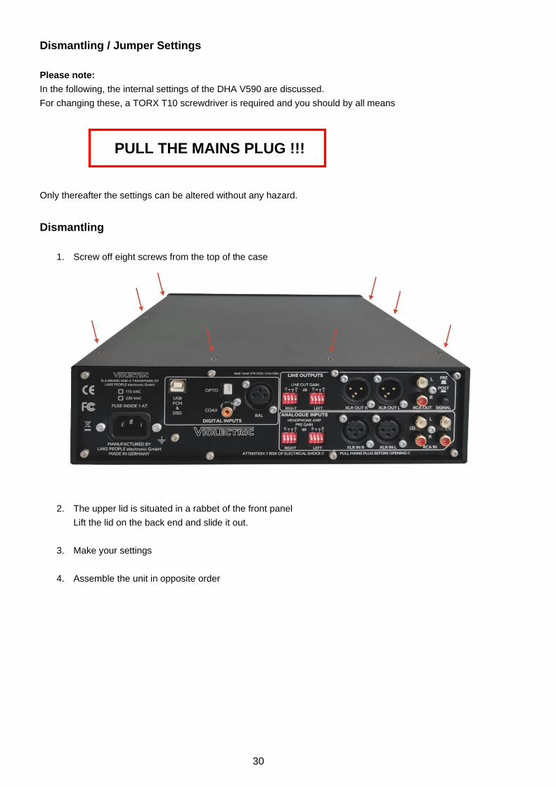
Dismantling / Jumper Settings Please note: In the following, the internal settings of the DHA V590 are discussed. For changing these, a TORX T10 screwdriver is required and you should by all means
PULL THE MAINS PLUG !!! Only thereafter the settings can be altered without any hazard. Dismantling
1. Screw off eight screws from the top of the case
2. The upper lid is situated in a rabbet of the front panel Lift the lid on the back end and slide it out.
3. Make your settings
4. Assemble the unit in opposite order
31
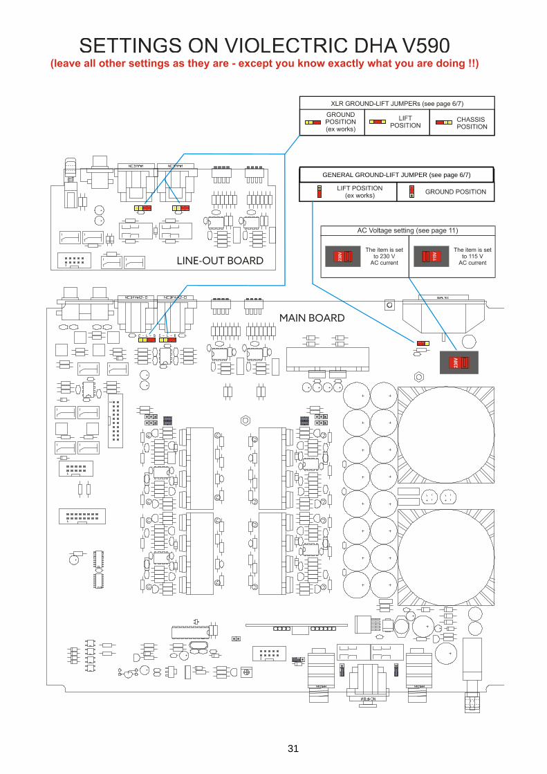
GENERAL GROUND-LIFT JUMPER (see page 6/7)
32
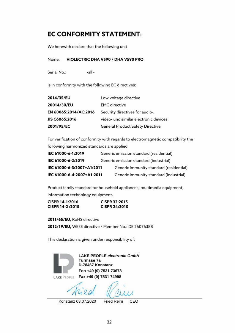
EC CONFORMITY STATEMENT: We herewith declare that the following unit
Name: VIOLECTRIC DHA V590 / DHA V590 PRO
Serial No.: -all -
is in conformity with the following EC directives:
2014/35/EU Low voltage directive
20014/30/EU EMC directive
EN 60065:2014/AC:2016 Security directives for audio-,
JIS C6065:2016 video- und similar electronic devices
2001/95/EC General Product Safety Directive
For verification of conformity with regards to electromagnetic compatibility the
following harmonized standards are applied:
IEC 61000-6-1:2019 Generic emission standard (residential)
IEC 61000-6-2:2019 Generic emission standard (industrial)
IEC 61000-6-3:2007+A1:2011 Generic immunity standard (residential)
IEC 61000-6-4:2007+A1:2011 Generic immunity standard (industrial)
Product family standard for household appliances, multimedia equipment,
information technology equipment.
CISPR 14-1:2016 CISPR 32:2015 CISPR 14-2 :2015 CISPR 24:2010
2011/65/EU, RoHS directive
2012/19/EU, WEEE directive / Member No.: DE 26076388
This declaration is given under responsibility of:
Konstanz 03.07.2020 Fried Reim CEO
LAKE PEOPLE electronic GmbH Turmsse 7a D-78467 Konstanz Fon +49 (0) 7531 73678 Fax +49 (0) 7531 74998
33
WARRENTY Since 1986 we are constructing and manufacturing sophisticated electronics for ambitious customers. Since the early beginnings we are trying hard by accompanying measures, the use of 1st choice components and multiple quality checks during production to avoid faults at large. We are quite effective in that and this is – amongst others - why we enjoy such a good reputation. Despite all accurateness faults may appear which may derogate the proper operation of your product. In this case your unit is protected by a 5-year Warranty! Needless to say that we will care for your product even after the expiration of the warranty. If it is necessary, please dispatch your item to: Lake People electronic GmbH Fon +49 (0) 7531 73678 Turmstrasse 7a Fax +49 (0) 7531 74998 78467 Konstanz E-Mail [email protected] Germany Web www.lake-people.de Your warranty claim begins with the date of purchase, which should be denoted on your proof of purchase. Do not forget to include the receipt of sales or a copy of the receipt. Please also include a short description of the fault(s). For the reshipment we need you correct address! Care for a safe packaging. Best is to use the original packaging. Please keep in mind that we cannot accept collect freight. We will grant a quick repair and quick return of the unit. In case of a warranty repair we will reship free of charge. Please denote here the serial number and the date of purchase:
Serial Number Date of Purchase

34
35
Inhalt Thema Seite Über 36 Sicherheitshinweise 37 Das Erde / Masse Konzept 38 Anschluss / Steckerbelegung 40 Allgemeines 42 Die Fernbedienung 44 Bockschaltbild 45 Power, Eingänge, Regler 46 RESAMPLING erklärt 48 Die D/A Wandler 49 PRE-GAIN erklärt 50 Line- und Kopfhörerausgänge 52 Signalverarbeitung 54 Fehlerauswertung 55 RESET 55 Software Steuerung 56 Filterkurven 57 Wissenswertes 58 Entsorgung 61 Technische Daten 61 Demontage 63 Jumper Setting 64 Konformitätserklärung 65 Garantie 66
ACHTUNG !!
DIE MIT DIESEM GERÄT ERZIELBAREN
LAUTSTÄRKEN KÖNNEN GEHÖRSCHÄDEN HERVORRUFEN ODER DIE ANGESCHLOSSENEN
KOPFHÖRER ZERSTÖREN!!

36
Herzlichen Dank, das Sie sich für ein Gerät von entschieden haben !!
ist eine Marke und eine Produktlinie der Lake People electronic GmbH. Die Lake People electronic GmbH entwickelt, produziert und vertreibt Produkte im professionellen Sektor z. B. für Rundfunk, Fernsehen, Flughäfen, Messehallen, Festspielhäuser, Theater, grosse Installationen oder private Studios. Aber auch im privaten Bereich erfreuen sich Produkte der Fa. Lake People wegen ihrer hohen Qualität einer wachsenden Beliebtheit. Mit der Marke und der Produktlinie soll der HiEnd Markt mit seinen anspruchvollen Bedürfnissen zielgerichtet bedient werden.
Wer entwickelt die Geräte ? Die Geräte werden ausschliesslich in Deutschland von Ingenieuren und Designern der Lake People electronic GmbH entwickelt. Das Entwickler-Team kann dabei auf über 30 Jahre Erfahrung und unzählige Produkte für den professionellen Bereich zurückgreifen. Im Hause Lake People wurden unter Anderem Anfang der ´90er Jahre des vergangenen Jahrhunderts die ersten deutschen 20 Bit A/D- und D/A Wandler entwickelt.
Wer produziert die Geräte ? Die Geräte werden ausschliesslich in Deutschland von der Fa. Lake People electronic GmbH oder im Umkreis der Firma ansässigen Lohnfertigern produziert. Die Fa. Lake People und damit auch legen Wert darauf, das im Inland produziert wird. Auch die Bauteile der Zulieferer werden so gewählt, das ein maximaler Teil der Wertschöpfung im Land erfolgt.
Wie gelangen die Geräte zum Kunden ? Die Geräte können im einschlägigen Fachhandel erworben werden. Falls in Ihrer Nähe kein Fachhändler zu finden ist, stehen dem potentiellen Kunden überregionale Partner (googlen hilft), der Vertrieb CMA Audio in München ( www.cma.audio ) und natürlich die Fa. Lake People electronic GmbH ( www.lake-people.de ) zur Verfügung.
… wenn mal was nicht so funktioniert wie es soll ? Geräte verfügen über eine Garantie von 5 Jahren !!
Innerhalb dieser Zeit sollten sie im Falle eines Defektes zum Hersteller eingeschickt werden. Natürlich steht dem Kunden auch nach Ablauf der Garantiezeit der volle Service von bzw. von Lake People zur Verfügung. Eine Versorgung mit Ersatzteilen garantieren wir für wenigsten 10 Jahre! Auch für technische Fragen können Sie sich gern an den Hersteller wenden.
is a subsidiary of
LAKE PEOPLE electronic GmbH
Turmstrasse 7a D-78467 Konstanz
Fon +49 (0) 7531 73678 Fax +49 (0) 7531 74998
www.lake-people.de www.lake-people.com
www.NIIMBUS-audio.de www.NIIMBUS-audio.com
www.violectric.de www.violectric.com
37
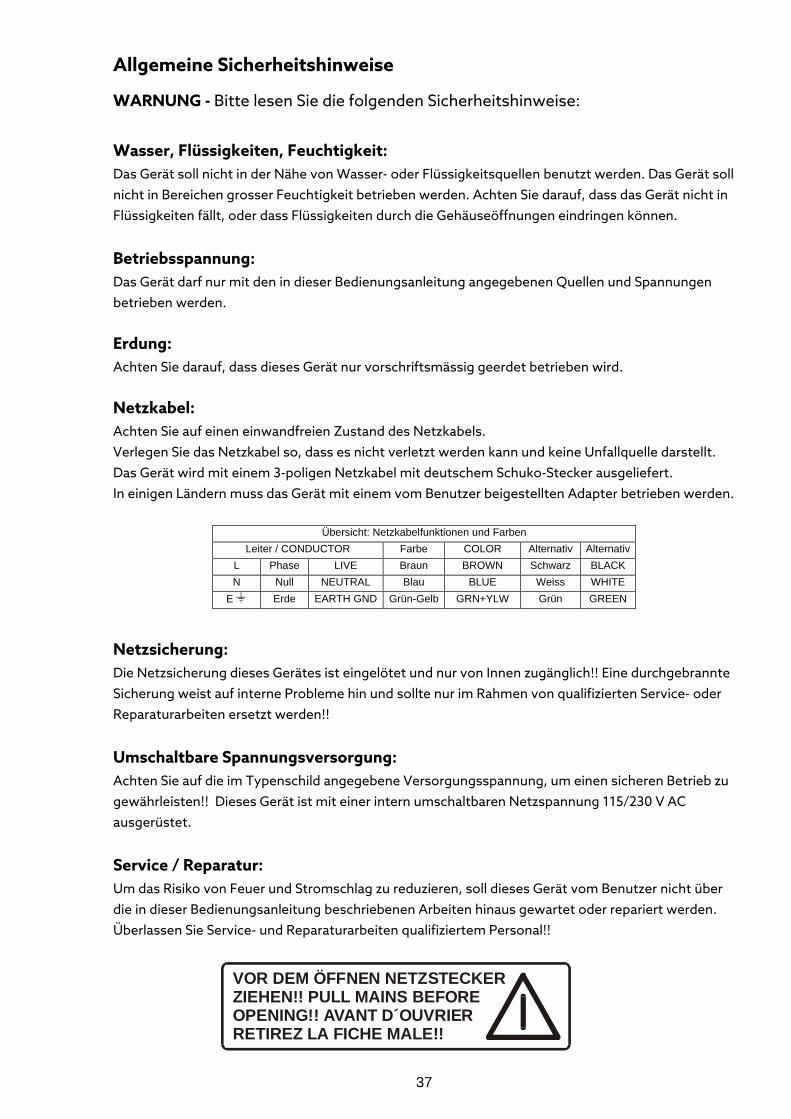
Allgemeine Sicherheitshinweise
WARNUNG - Bitte lesen Sie die folgenden Sicherheitshinweise: Wasser, Flüssigkeiten, Feuchtigkeit: Das Gerät soll nicht in der Nähe von Wasser- oder Flüssigkeitsquellen benutzt werden. Das Gerät soll nicht in Bereichen grosser Feuchtigkeit betrieben werden. Achten Sie darauf, dass das Gerät nicht in Flüssigkeiten fällt, oder dass Flüssigkeiten durch die Gehäuseöffnungen eindringen können.
Betriebsspannung: Das Gerät darf nur mit den in dieser Bedienungsanleitung angegebenen Quellen und Spannungen betrieben werden.
Erdung: Achten Sie darauf, dass dieses Gerät nur vorschriftsmässig geerdet betrieben wird.
Netzkabel: Achten Sie auf einen einwandfreien Zustand des Netzkabels. Verlegen Sie das Netzkabel so, dass es nicht verletzt werden kann und keine Unfallquelle darstellt. Das Gerät wird mit einem 3-poligen Netzkabel mit deutschem Schuko-Stecker ausgeliefert. In einigen Ländern muss das Gerät mit einem vom Benutzer beigestellten Adapter betrieben werden.
Übersicht: Netzkabelfunktionen und Farben Leiter / CONDUCTOR Farbe COLOR Alternativ Alternativ
L Phase LIVE Braun BROWN Schwarz BLACK N Null NEUTRAL Blau BLUE Weiss WHITE
E Erde EARTH GND Grün-Gelb GRN+YLW Grün GREEN
Netzsicherung: Die Netzsicherung dieses Gerätes ist eingelötet und nur von Innen zugänglich!! Eine durchgebrannte Sicherung weist auf interne Probleme hin und sollte nur im Rahmen von qualifizierten Service- oder Reparaturarbeiten ersetzt werden!!
Umschaltbare Spannungsversorgung: Achten Sie auf die im Typenschild angegebene Versorgungsspannung, um einen sicheren Betrieb zu gewährleisten!! Dieses Gerät ist mit einer intern umschaltbaren Netzspannung 115/230 V AC ausgerüstet.
Service / Reparatur: Um das Risiko von Feuer und Stromschlag zu reduzieren, soll dieses Gerät vom Benutzer nicht über die in dieser Bedienungsanleitung beschriebenen Arbeiten hinaus gewartet oder repariert werden. Überlassen Sie Service- und Reparaturarbeiten qualifiziertem Personal!!
VOR DEM ÖFFNEN NETZSTECKERZIEHEN!! PULL MAINS BEFOREOPENING!! AVANT D´OUVRIERRETIREZ LA FICHE MALE!!
38
Elektromagnetische Verträglichkeit: Dieses Gerät entspricht internationalen Spezifikationen, die am Ende dieser Bedienungsanleitung in der KONFORMITÄTS-ERKLÄRUNG beschrieben sind mit den folgenden Voraussetzungen: - dieses Gerät strahlt keine störenden Emissionen aus
- dieses Gerät kann in störenden Umgebungen betrieben werden, auch wenn diese den beabsichtigten Einsatzzweck des Gerätes beeinträchtigen - der Betrieb dieses Gerätes in Umgebungen mit hohen elektromagnetischen Feldern
sollte vermieden werden
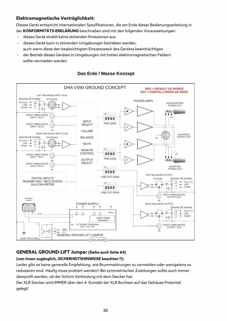
Das Erde / Masse Konzept
GENERAL GROUND-LIFT Jumper (Siehe auch Seite 64) (von innen zugänglich, SICHERHEITSHINWEISE beachten !!): Leider gibt es keine generelle Empfehlung, wie Brummstörungen zu vermeiden oder wenigstens zu reduzieren sind. Häufig muss probiert werden!! Bei symmetrischen Zuleitungen sollte auch immer überprüft werden, ob der Schirm Verbindung mit dem Stecker hat. Der XLR Stecker wird IMMER über den 4. Kontakt der XLR Buchsen auf das Gehäuse-Potential gelegt!
39
Ab Werk ist der General Ground-Lift Jumper auf LIFT gesetzt. Die Verbindung zwischen internem Masse-Bezugspunkt und Erde wird hierbei für Gleichspannungen und niedrige Frequenzen (< 160 Hz) getrennt. Höherfrequente Störungen werden weiter nach Masse abgeleitet. Die LIFT-Stellung kann hilfreich sein, wenn z.B. aufgrund verschiedener Massepotentiale Brumm generiert wird.
Der interne Masse-Bezugspunkt kann im Gerät über einen Jumper von LIFT auf Ground gelegt werden.
Wie aus obiger Abbildung ersichtlich, kann das Masse/Erde-Verhältnis der symmetrischen ANALOGEN Eingänge modifiziert werden. Die elektrische Sicherheit ist immer gewährleistet, da der Schutzleiter PE fest am Gehäuse liegt!!
XLR GROUD-LIFT Jumper (Siehe auch Seite 64) (von innen zugänglich, SICHERHEITSHINWEISE beachten !!): G(ROUND): Ab Werk sind alle Jumper auf G(ROUND) gesetzt. Pin 1 ist mit dem internen Masse-Bezugspunkt verbunden. HF Störungen werden über
einen 100 nF Kondensator auf das Gehäuse abgeleitet. L(IFT): Pin 1 ist nicht mit dem internen Masse-Bezugspunkt verbunden. HF Störungen werden
über einen 100 nF Kondensator auf das Gehäuse abgeleitet. Diese Stellung ist meist nur mit Transformatoren sinnvoll!!
C(ASE): Pin 1 ist mit dem Gehäuse verbunden, der 100 nF Kondensator ist überbrückt. Diese Jumperstellung kann mit dem General GROUND-LIFT Jumper variiert werden.
Sollte von den Werkseinstellungen abgewichen werden, können EMV Probleme entstehen.
Diese liegen im Verantwortungsbereich des Nutzers!! Ändern Sie diese Einstellungen also nur,
wenn Sie wissen was Sie tun!!!
40
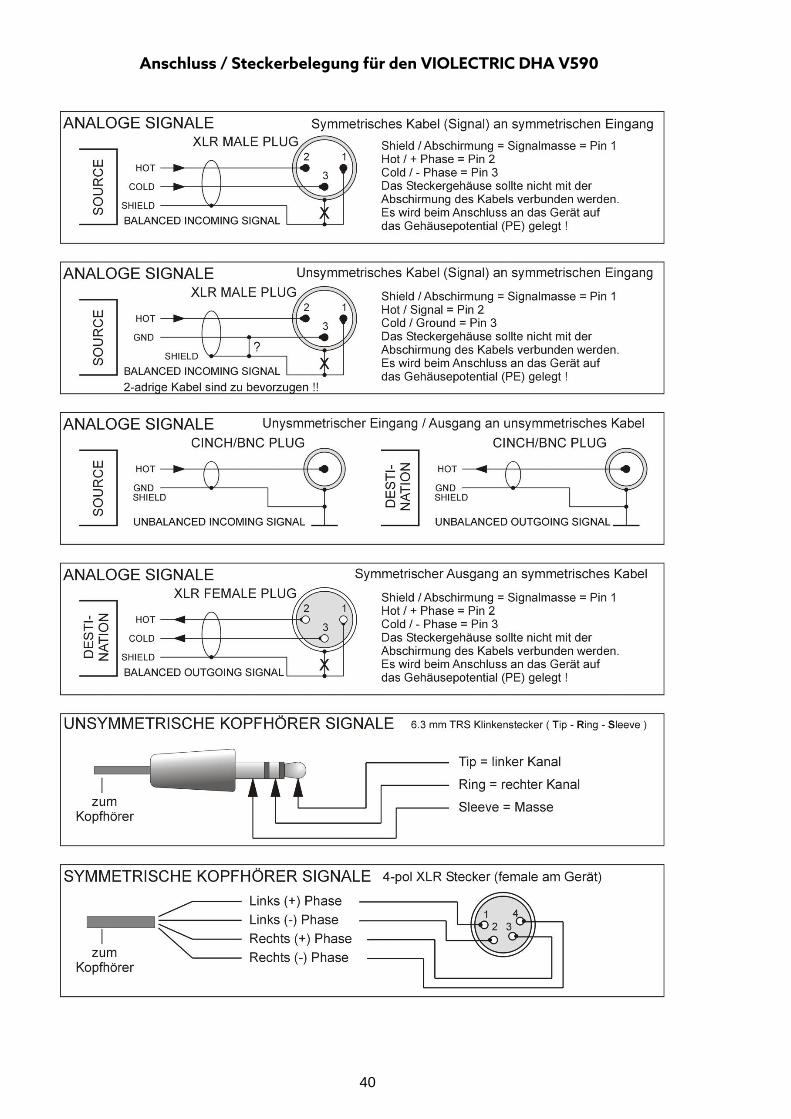
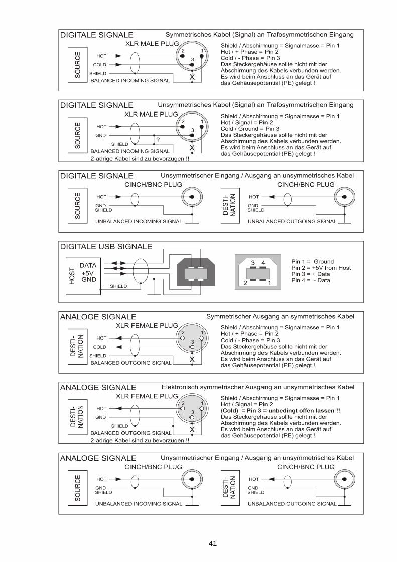
Anschluss / Steckerbelegung für den VIOLECTRIC DHA V590
41
42
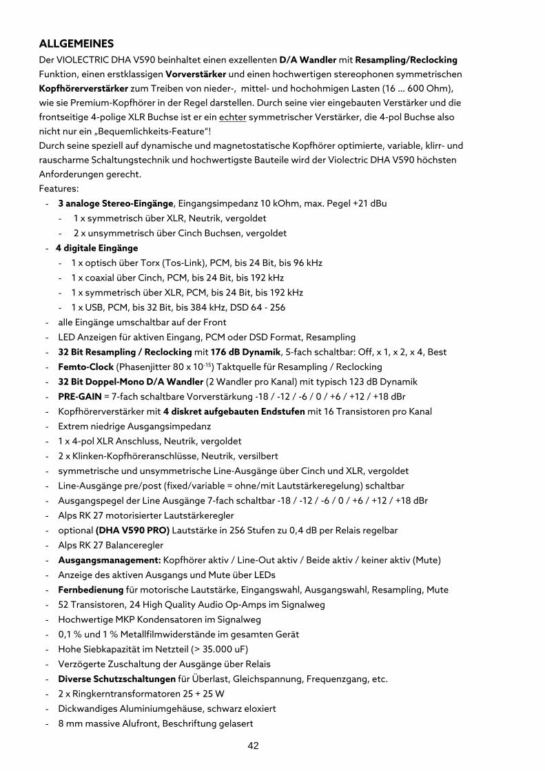
ALLGEMEINES Der VIOLECTRIC DHA V590 beinhaltet einen exzellenten D/A Wandler mit Resampling/Reclocking Funktion, einen erstklassigen Vorverstärker und einen hochwertigen stereophonen symmetrischen Kopfhörerverstärker zum Treiben von nieder-, mittel- und hochohmigen Lasten (16 … 600 Ohm), wie sie Premium-Kopfhörer in der Regel darstellen. Durch seine vier eingebauten Verstärker und die frontseitige 4-polige XLR Buchse ist er ein echter symmetrischer Verstärker, die 4-pol Buchse also nicht nur ein „Bequemlichkeits-Feature“! Durch seine speziell auf dynamische und magnetostatische Kopfhörer optimierte, variable, klirr- und rauscharme Schaltungstechnik und hochwertigste Bauteile wird der Violectric DHA V590 höchsten Anforderungen gerecht. Features:
- 3 analoge Stereo-Eingänge, Eingangsimpedanz 10 kOhm, max. Pegel +21 dBu
- 1 x symmetrisch über XLR, Neutrik, vergoldet
- 2 x unsymmetrisch über Cinch Buchsen, vergoldet
- 4 digitale Eingänge
- 1 x optisch über Torx (Tos-Link), PCM, bis 24 Bit, bis 96 kHz
- 1 x coaxial über Cinch, PCM, bis 24 Bit, bis 192 kHz
- 1 x symmetrisch über XLR, PCM, bis 24 Bit, bis 192 kHz
- 1 x USB, PCM, bis 32 Bit, bis 384 kHz, DSD 64 - 256
- alle Eingänge umschaltbar auf der Front
- LED Anzeigen für aktiven Eingang, PCM oder DSD Format, Resampling
- 32 Bit Resampling / Reclocking mit 176 dB Dynamik, 5-fach schaltbar: Off, x 1, x 2, x 4, Best
- Femto-Clock (Phasenjitter 80 x 10-15) Taktquelle für Resampling / Reclocking
- 32 Bit Doppel-Mono D/A Wandler (2 Wandler pro Kanal) mit typisch 123 dB Dynamik
- PRE-GAIN = 7-fach schaltbare Vorverstärkung -18 / -12 / -6 / 0 / +6 / +12 / +18 dBr
- Kopfhörerverstärker mit 4 diskret aufgebauten Endstufen mit 16 Transistoren pro Kanal
- Extrem niedrige Ausgangsimpedanz
- 1 x 4-pol XLR Anschluss, Neutrik, vergoldet
- 2 x Klinken-Kopfhöreranschlüsse, Neutrik, versilbert
- symmetrische und unsymmetrische Line-Ausgänge über Cinch und XLR, vergoldet
- Line-Ausgänge pre/post (fixed/variable = ohne/mit Lautstärkeregelung) schaltbar
- Ausgangspegel der Line Ausgänge 7-fach schaltbar -18 / -12 / -6 / 0 / +6 / +12 / +18 dBr
- Alps RK 27 motorisierter Lautstärkeregler
- optional (DHA V590 PRO) Lautstärke in 256 Stufen zu 0,4 dB per Relais regelbar
- Alps RK 27 Balanceregler
- Ausgangsmanagement: Kopfhörer aktiv / Line-Out aktiv / Beide aktiv / keiner aktiv (Mute)
- Anzeige des aktiven Ausgangs und Mute über LEDs
- Fernbedienung für motorische Lautstärke, Eingangswahl, Ausgangswahl, Resampling, Mute
- 52 Transistoren, 24 High Quality Audio Op-Amps im Signalweg
- Hochwertige MKP Kondensatoren im Signalweg
- 0,1 % und 1 % Metallfilmwiderstände im gesamten Gerät
- Hohe Siebkapazität im Netzteil (> 35.000 uF)
- Verzögerte Zuschaltung der Ausgänge über Relais
- Diverse Schutzschaltungen für Überlast, Gleichspannung, Frequenzgang, etc.
- 2 x Ringkerntransformatoren 25 + 25 W
- Dickwandiges Aluminiumgehäuse, schwarz eloxiert
- 8 mm massive Alufront, Beschriftung gelasert
43
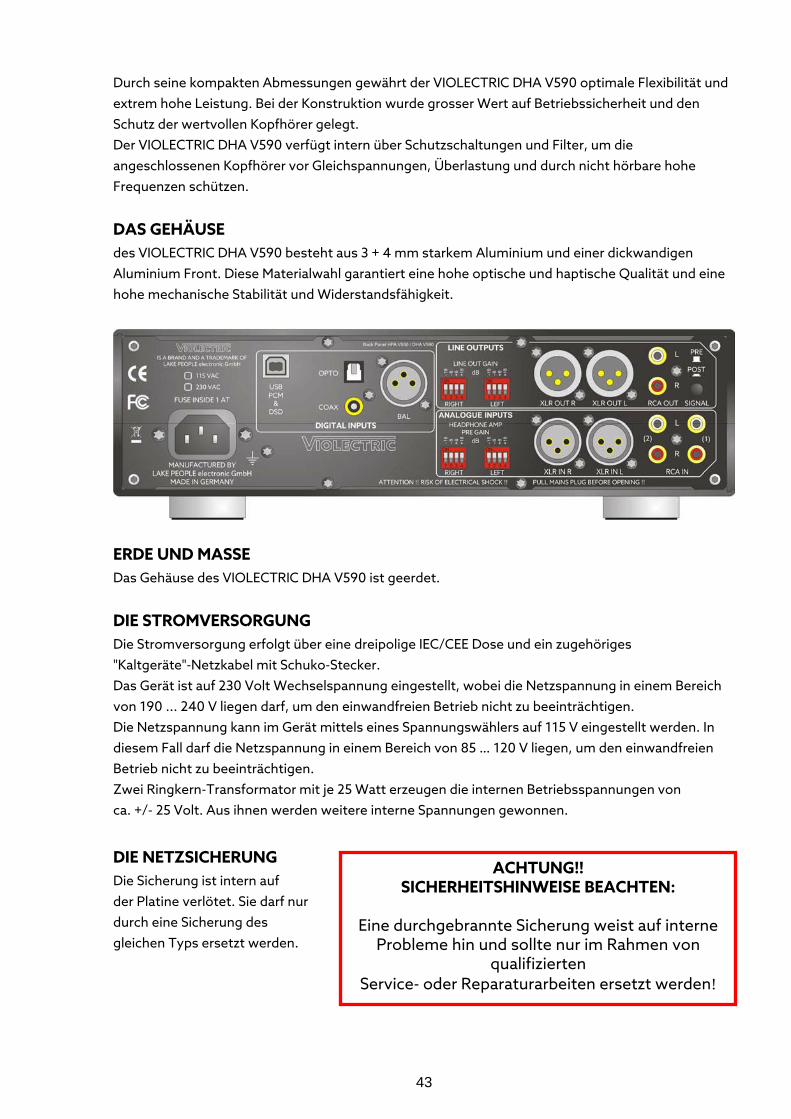
ACHTUNG!! SICHERHEITSHINWEISE BEACHTEN:
Eine durchgebrannte Sicherung weist auf interne
Probleme hin und sollte nur im Rahmen von qualifizierten
Service- oder Reparaturarbeiten ersetzt werden!
Durch seine kompakten Abmessungen gewährt der VIOLECTRIC DHA V590 optimale Flexibilität und extrem hohe Leistung. Bei der Konstruktion wurde grosser Wert auf Betriebssicherheit und den Schutz der wertvollen Kopfhörer gelegt. Der VIOLECTRIC DHA V590 verfügt intern über Schutzschaltungen und Filter, um die angeschlossenen Kopfhörer vor Gleichspannungen, Überlastung und durch nicht hörbare hohe Frequenzen schützen.
DAS GEHÄUSE des VIOLECTRIC DHA V590 besteht aus 3 + 4 mm starkem Aluminium und einer dickwandigen Aluminium Front. Diese Materialwahl garantiert eine hohe optische und haptische Qualität und eine hohe mechanische Stabilität und Widerstandsfähigkeit.
ERDE UND MASSE Das Gehäuse des VIOLECTRIC DHA V590 ist geerdet.
DIE STROMVERSORGUNG Die Stromversorgung erfolgt über eine dreipolige IEC/CEE Dose und ein zugehöriges "Kaltgeräte"-Netzkabel mit Schuko-Stecker. Das Gerät ist auf 230 Volt Wechselspannung eingestellt, wobei die Netzspannung in einem Bereich von 190 ... 240 V liegen darf, um den einwandfreien Betrieb nicht zu beeinträchtigen. Die Netzspannung kann im Gerät mittels eines Spannungswählers auf 115 V eingestellt werden. In diesem Fall darf die Netzspannung in einem Bereich von 85 … 120 V liegen, um den einwandfreien Betrieb nicht zu beeinträchtigen. Zwei Ringkern-Transformator mit je 25 Watt erzeugen die internen Betriebsspannungen von ca. +/- 25 Volt. Aus ihnen werden weitere interne Spannungen gewonnen.
DIE NETZSICHERUNG Die Sicherung ist intern auf der Platine verlötet. Sie darf nur durch eine Sicherung des gleichen Typs ersetzt werden.
44
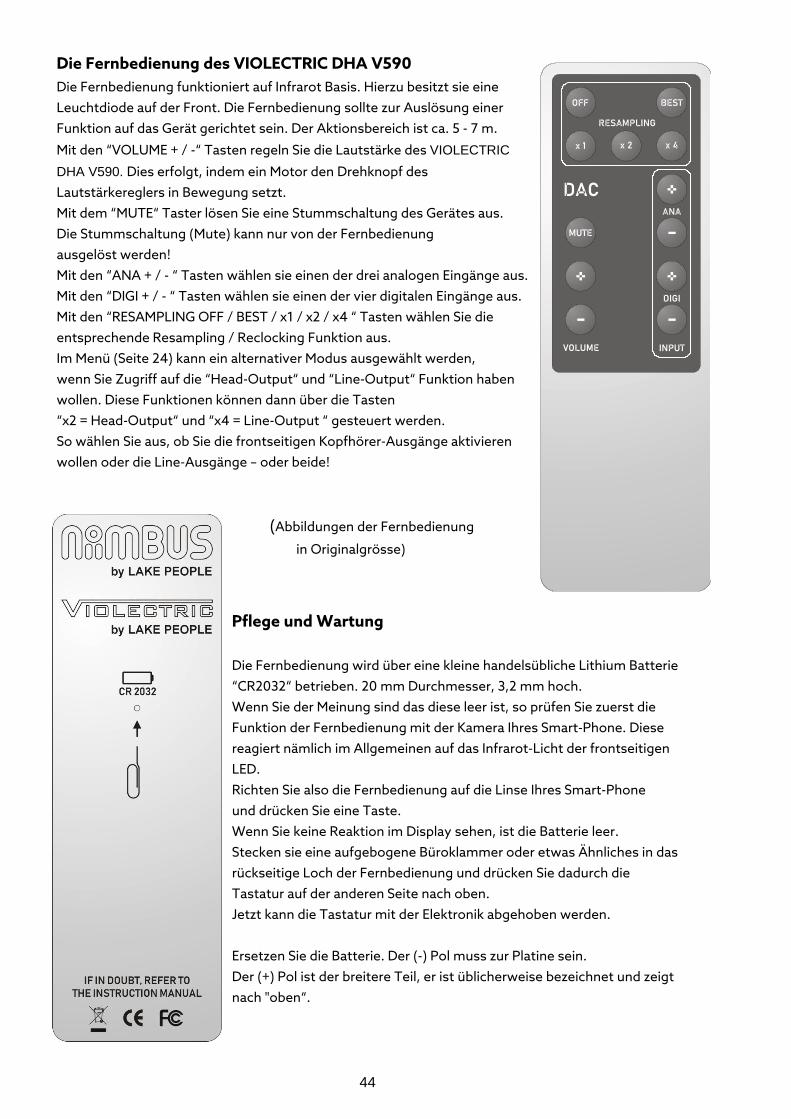
Die Fernbedienung des VIOLECTRIC DHA V590 Die Fernbedienung funktioniert auf Infrarot Basis. Hierzu besitzt sie eine Leuchtdiode auf der Front. Die Fernbedienung sollte zur Auslösung einer Funktion auf das Gerät gerichtet sein. Der Aktionsbereich ist ca. 5 - 7 m.
Mit den “VOLUME + / -“ Tasten regeln Sie die Lautstärke des VIOLECTRIC DHA V590. Dies erfolgt, indem ein Motor den Drehknopf des Lautstärkereglers in Bewegung setzt. Mit dem “MUTE“ Taster lösen Sie eine Stummschaltung des Gerätes aus. Die Stummschaltung (Mute) kann nur von der Fernbedienung ausgelöst werden! Mit den “ANA + / - “ Tasten wählen sie einen der drei analogen Eingänge aus. Mit den “DIGI + / - “ Tasten wählen sie einen der vier digitalen Eingänge aus. Mit den “RESAMPLING OFF / BEST / x1 / x2 / x4 “ Tasten wählen Sie die entsprechende Resampling / Reclocking Funktion aus. Im Menü (Seite 24) kann ein alternativer Modus ausgewählt werden, wenn Sie Zugriff auf die “Head-Output“ und “Line-Output“ Funktion haben wollen. Diese Funktionen können dann über die Tasten “x2 = Head-Output“ und “x4 = Line-Output “ gesteuert werden. So wählen Sie aus, ob Sie die frontseitigen Kopfhörer-Ausgänge aktivieren wollen oder die Line-Ausgänge – oder beide!
(Abbildungen der Fernbedienung
in Originalgrösse)
Pflege und Wartung
Die Fernbedienung wird über eine kleine handelsübliche Lithium Batterie “CR2032“ betrieben. 20 mm Durchmesser, 3,2 mm hoch. Wenn Sie der Meinung sind das diese leer ist, so prüfen Sie zuerst die Funktion der Fernbedienung mit der Kamera Ihres Smart-Phone. Diese reagiert nämlich im Allgemeinen auf das Infrarot-Licht der frontseitigen LED. Richten Sie also die Fernbedienung auf die Linse Ihres Smart-Phone und drücken Sie eine Taste. Wenn Sie keine Reaktion im Display sehen, ist die Batterie leer. Stecken sie eine aufgebogene Büroklammer oder etwas Ähnliches in das rückseitige Loch der Fernbedienung und drücken Sie dadurch die Tastatur auf der anderen Seite nach oben. Jetzt kann die Tastatur mit der Elektronik abgehoben werden. Ersetzen Sie die Batterie. Der (-) Pol muss zur Platine sein. Der (+) Pol ist der breitere Teil, er ist üblicherweise bezeichnet und zeigt nach "oben“.
45
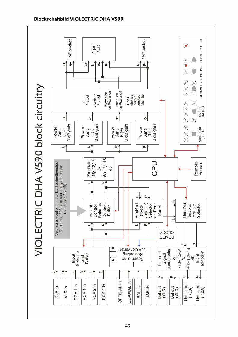
Blockschaltbild VIOLECTRIC DHA V590
46
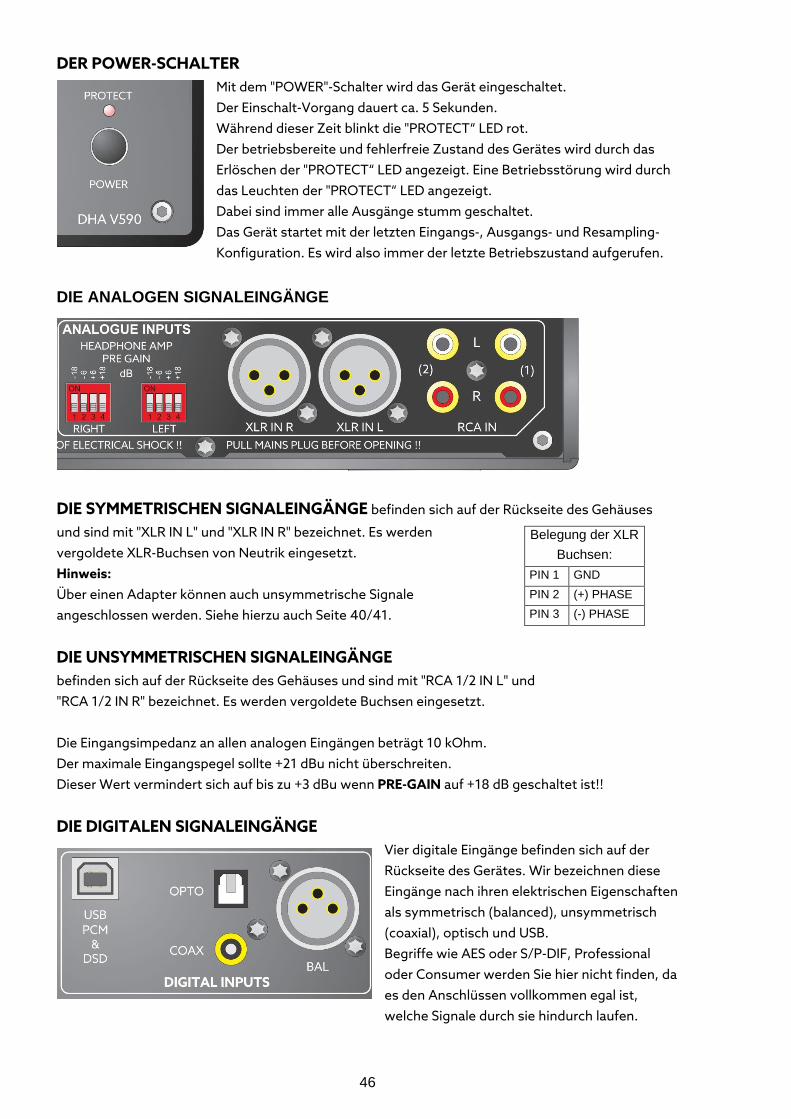
DER POWER-SCHALTER Mit dem "POWER"-Schalter wird das Gerät eingeschaltet. Der Einschalt-Vorgang dauert ca. 5 Sekunden. Während dieser Zeit blinkt die "PROTECT“ LED rot. Der betriebsbereite und fehlerfreie Zustand des Gerätes wird durch das Erlöschen der "PROTECT“ LED angezeigt. Eine Betriebsstörung wird durch das Leuchten der "PROTECT“ LED angezeigt. Dabei sind immer alle Ausgänge stumm geschaltet. Das Gerät startet mit der letzten Eingangs-, Ausgangs- und Resampling-Konfiguration. Es wird also immer der letzte Betriebszustand aufgerufen.
DIE ANALOGEN SIGNALEINGÄNGE
DIE SYMMETRISCHEN SIGNALEINGÄNGE befinden sich auf der Rückseite des Gehäuses
und sind mit "XLR IN L" und "XLR IN R" bezeichnet. Es werden vergoldete XLR-Buchsen von Neutrik eingesetzt. Hinweis: Über einen Adapter können auch unsymmetrische Signale angeschlossen werden. Siehe hierzu auch Seite 40/41.
DIE UNSYMMETRISCHEN SIGNALEINGÄNGE
befinden sich auf der Rückseite des Gehäuses und sind mit "RCA 1/2 IN L" und "RCA 1/2 IN R" bezeichnet. Es werden vergoldete Buchsen eingesetzt. Die Eingangsimpedanz an allen analogen Eingängen beträgt 10 kOhm. Der maximale Eingangspegel sollte +21 dBu nicht überschreiten. Dieser Wert vermindert sich auf bis zu +3 dBu wenn PRE-GAIN auf +18 dB geschaltet ist!!
DIE DIGITALEN SIGNALEINGÄNGE
Vier digitale Eingänge befinden sich auf der Rückseite des Gerätes. Wir bezeichnen diese Eingänge nach ihren elektrischen Eigenschaften als symmetrisch (balanced), unsymmetrisch (coaxial), optisch und USB. Begriffe wie AES oder S/P-DIF, Professional oder Consumer werden Sie hier nicht finden, da es den Anschlüssen vollkommen egal ist, welche Signale durch sie hindurch laufen.
Belegung der XLR Buchsen:
PIN 1 GND PIN 2 (+) PHASE PIN 3 (-) PHASE
47
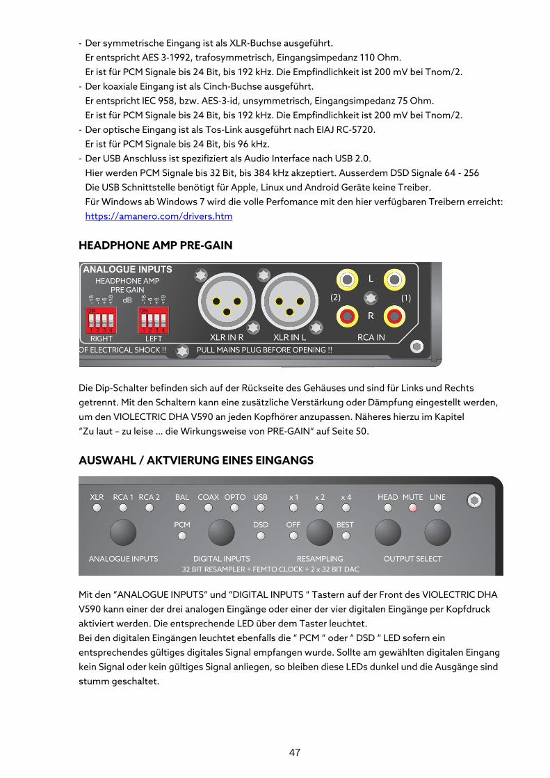
- Der symmetrische Eingang ist als XLR-Buchse ausgeführt. Er entspricht AES 3-1992, trafosymmetrisch, Eingangsimpedanz 110 Ohm. Er ist für PCM Signale bis 24 Bit, bis 192 kHz. Die Empfindlichkeit ist 200 mV bei Tnom/2. - Der koaxiale Eingang ist als Cinch-Buchse ausgeführt.
Er entspricht IEC 958, bzw. AES-3-id, unsymmetrisch, Eingangsimpedanz 75 Ohm. Er ist für PCM Signale bis 24 Bit, bis 192 kHz. Die Empfindlichkeit ist 200 mV bei Tnom/2. - Der optische Eingang ist als Tos-Link ausgeführt nach EIAJ RC-5720. Er ist für PCM Signale bis 24 Bit, bis 96 kHz. - Der USB Anschluss ist spezifiziert als Audio Interface nach USB 2.0.
Hier werden PCM Signale bis 32 Bit, bis 384 kHz akzeptiert. Ausserdem DSD Signale 64 - 256 Die USB Schnittstelle benötigt für Apple, Linux und Android Geräte keine Treiber. Für Windows ab Windows 7 wird die volle Perfomance mit den hier verfügbaren Treibern erreicht: https://amanero.com/drivers.htm
HEADPHONE AMP PRE-GAIN
Die Dip-Schalter befinden sich auf der Rückseite des Gehäuses und sind für Links und Rechts getrennt. Mit den Schaltern kann eine zusätzliche Verstärkung oder Dämpfung eingestellt werden, um den VIOLECTRIC DHA V590 an jeden Kopfhörer anzupassen. Näheres hierzu im Kapitel “Zu laut – zu leise … die Wirkungsweise von PRE-GAIN“ auf Seite 50.
AUSWAHL / AKTVIERUNG EINES EINGANGS
Mit den “ANALOGUE INPUTS“ und “DIGITAL INPUTS “ Tastern auf der Front des VIOLECTRIC DHA V590 kann einer der drei analogen Eingänge oder einer der vier digitalen Eingänge per Kopfdruck aktiviert werden. Die entsprechende LED über dem Taster leuchtet. Bei den digitalen Eingängen leuchtet ebenfalls die “ PCM “ oder “ DSD “ LED sofern ein entsprechendes gültiges digitales Signal empfangen wurde. Sollte am gewählten digitalen Eingang kein Signal oder kein gültiges Signal anliegen, so bleiben diese LEDs dunkel und die Ausgänge sind stumm geschaltet.
48
Die Eingänge können auch per Fernbedienung umgeschaltet werden: Drücken Sie die “ANA + / -“ Tasten auf der Fernbedienung, um die analogen Eingänge umzuschalten. Drücken Sie die “DIG + / -“ Tasten auf der Fernbedienung, um die digitalen Eingänge umzuschalten.
RESAMPLING ist eine mächtige Funktion, um verjitterte Signale in hochwertige digitale Signale zurück zu verwandeln und um den Klang von Quellen mit 44.1 oder 48 kHz aufzuwerten indem man sie auf eine höhere Bitrate transferiert. Das gilt besonders für den optischen und den USB Eingang, deren Qualität oft unter den optischen Kabeln bzw. den suboptimalen Ausgängen von Computern leiden. Durch den Resampling-Prozess wird jeglicher Jitter praktisch vollständig eliminiert. So ist grundsätzlich kein “asynchrones USB“ nötig, es ist aber trotzdem in die USB Software implementiert. Das alles ist kein grosses Geheimnis, sondern wird durch sogenannte Sample-Rate Konverter ermöglicht, die seit Mitte der 90er Jahre des letzten Jahrhunderts verfügbar sind. Während Anfangs ein Sample-Rate Konverter mit 20 Bit bei einer Dynamik von knapp 100 dB nur in einem Verhältnis 1:2 bis 2:1 (z. B. 44.1 -> 88.2 kHz Sample-Rate) arbeiten konnte, sind heute im DHA V590 Verhältnisse von 1:48 bis 48:1 (44.1-> 176.4 kHz = 1 : 4) machbar und wegen einer Bitbreite von 32 Bit mit einer Dynamik und Klirrdämpfung von knapp 180 dB! Im Prinzip wird der digitale Datenstrom in einem nur zu diesem Zweck bestimmten DSP taktneutral (asynchron) zerlegt und mit einer (fast) beliebigen Sample-Rate rekombiniert. Die Qualität des Resampling ist direkt abhängig von der Qualität des Taktgenerators. Deshalb wird im DHA V590 ein spezieller Low-Jitter Oszillator verwendet – die Femto Clock! (Phasen-Jitter < 80 fs = Femtosekunden = 80x10-15) Sie verfügt darüber hinaus über eine Low-Noise Stromversorgung. Durch obige Prozesse verschwindet jeglicher eventuell vorhandener Jitter praktisch vollständig, weiter können durch die höhere Sample-Rate die analogen Filter nach dem Wandler deutlich entspannter und “musikalischer“ ausgelegt werden. Auch werden alle Eingangsdaten auf 32 Bit Wortlänge ergänzt.
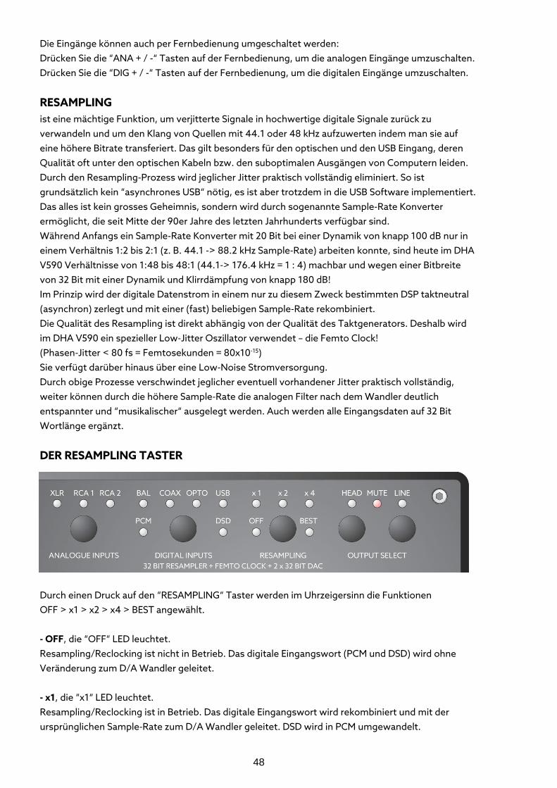
DER RESAMPLING TASTER
Durch einen Druck auf den “RESAMPLING“ Taster werden im Uhrzeigersinn die Funktionen OFF > x1 > x2 > x4 > BEST angewählt. - OFF, die “OFF“ LED leuchtet. Resampling/Reclocking ist nicht in Betrieb. Das digitale Eingangswort (PCM und DSD) wird ohne Veränderung zum D/A Wandler geleitet. - x1, die “x1“ LED leuchtet. Resampling/Reclocking ist in Betrieb. Das digitale Eingangswort wird rekombiniert und mit der ursprünglichen Sample-Rate zum D/A Wandler geleitet. DSD wird in PCM umgewandelt.
49
- x2, die “x2“ LED leuchtet. Resampling/Reclocking ist in Betrieb. Das digitale Eingangswort wird rekombiniert und mit der doppelten Sample-Rate zum D/A Wandler geleitet. DSD wird in PCM umgewandelt. - x4, die gelbe “x4“ LED leuchtet. Resampling/Reclocking ist in Betrieb. Das digitale Eingangswort wird rekombiniert und mit der vierfachen Sample-Rate zum D/A Wandler geleitet. DSD wird in PCM umgewandelt. - BEST, die “BEST“ LED leuchtet Resampling/Reclocking ist in Betrieb. Das digitale Eingangswort (PCM und DSD) wird rekombiniert und mit einer Sample-Rate von 96 kHz zum D/A Wandler geleitet. Dies ist die Frequenz, in der die meisten modernen Wandler optimal arbeiten. DSD wird in PCM umgewandelt. Mit der Fernbedienung können Sie auf obige Funktionen direkt zugreifen.
DIE DIGITAL-ANALOG WANDLER Die D/A Wandler beinhalten die einstellbaren digitalen Filter (siehe auch Software Menü 2 auf Seite 56), die eigentlichen D/A Wandler und die analogen Ausgangsfilter. Es werden 32 Bit Delta-Sigma D/A Wandler (AKM 4490) in Doppel-Mono Architektur verwendet - also zwei D/A Wandler pro Kanal. Sie zeichnen sich aus durch eine maximale Sample Rate bis 768 kHz, THD+N –112 dB und 123 dB Dynamik. Durch die Doppel-Mono Architektur wird eine grössere Linearität und geringeres Rauschen erreicht. Ein ankommendes 16, 20 oder 24 Bit Datenwort wird in den D/A Wandlern auf 32 Bit ergänzt falls es nicht schon vorher über den Resampling/Reclocking Prozess auf 32 Bit ergänzt wurde. Durch das hohe Oversampling der Delta-Sigma Wandler ist die Frequenz der digitalen (Stör)-signale sehr gross zur analogen Nutzfrequenz. Es müssen an die folgenden analogen Tiefpassfilter nur noch geringe Anforderungen bezüglich ihrer Dämpfungseigenschaften gestellt werden, sie sind deshalb als "musikalische" 2-Pole realisiert.
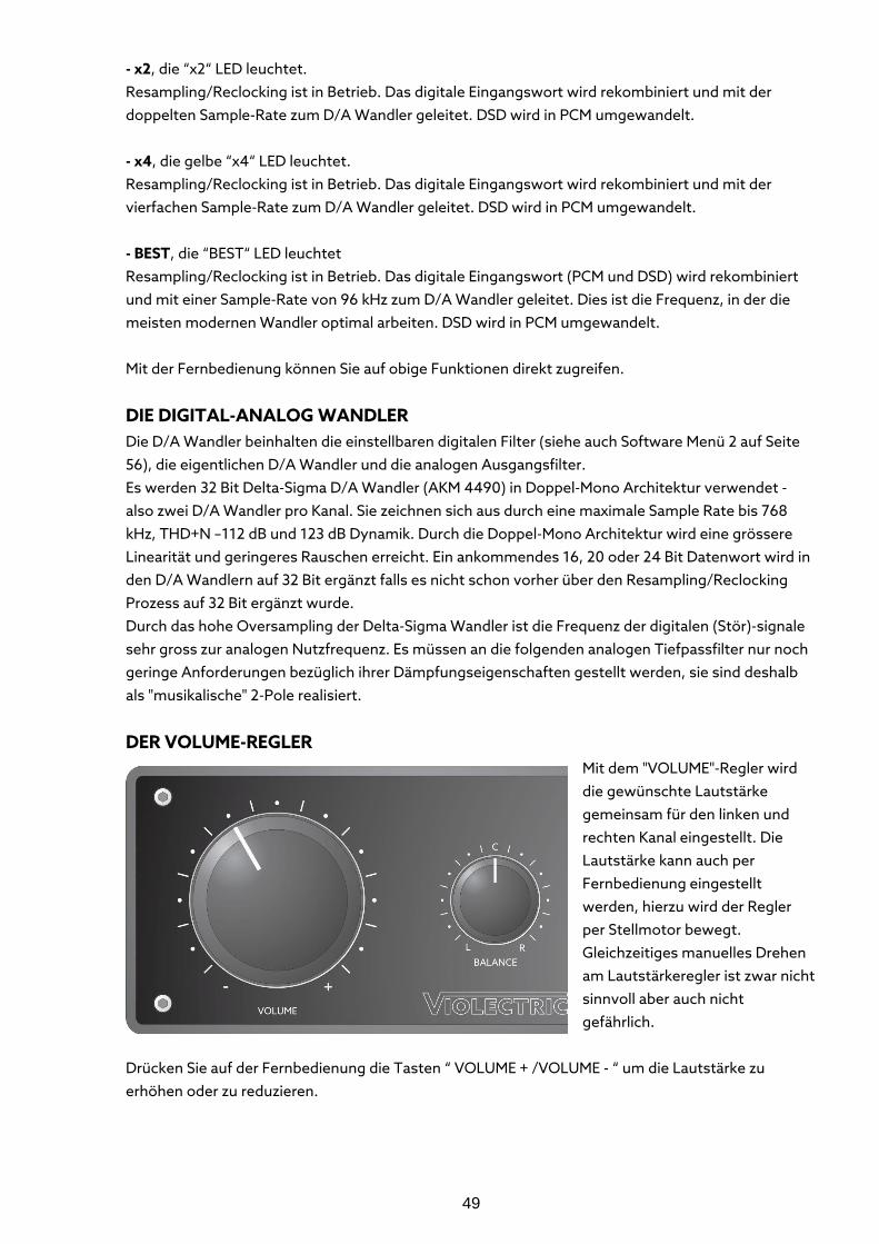
DER VOLUME-REGLER
Mit dem "VOLUME"-Regler wird die gewünschte Lautstärke gemeinsam für den linken und rechten Kanal eingestellt. Die Lautstärke kann auch per Fernbedienung eingestellt werden, hierzu wird der Regler per Stellmotor bewegt. Gleichzeitiges manuelles Drehen am Lautstärkeregler ist zwar nicht sinnvoll aber auch nicht gefährlich.
Drücken Sie auf der Fernbedienung die Tasten “ VOLUME + /VOLUME - “ um die Lautstärke zu erhöhen oder zu reduzieren.
50
DER BALANCE-REGLER dient zum Korrigieren leichter Lautstärkeunterschiede zwischen links und rechts. Die können ihre Ursache haben in falsch aufgenommenen Quellen, den zwar noch im Toleranzfeld befindlichen, aber trotzdem bemerkbaren Unterschieden zwischen rechtem und linkem Kopfhörer oder aber einem ungleichen Hörvermögen. All dies lässt sich behutsam ausgleichen in einem Bereich von ca. +/- 6 dB. Der Balanceregler verfügt über eine präzise Mittelrast, wenn er nicht benötigt wird. Um die perfekte Übersprechdämpfung des VIOLECTRIC DHA V590 nicht zu gefährden, wirkt er nur auf den rechten Kanal.
DIE VERSTÄRKER Die Eingangssignale werden in speziell für diese Anwendung konstruierten und mit 2x8 Transistoren pro Kanal ausgestatteten Verstärkern zugeführt. Wegen des echten symmetrischen Betriebs hat der VIOLECTRIC DHA V590 vier davon! Insgesamt sind 32 der über 50 Transistoren des Gerätes für die Verstärkung zuständig. Der Frequenzbereich reicht von 5 Hz – 250 kHz (-0,5 dB) um eine im Hörbereich absolut lineare Übertragung zu gewährleisten. Die Gesamtverstärkung ist auf 0 dB unsymmetrisch respektive +6 dB symmetrisch festgelegt. Durch diese Massnahme wird geringstes Eigenrauschen generiert.
Zu laut – zu leise … die Wirkungsweise von PRE-GAIN Der VIOLECTRIC DHA V590 ist dazu gedacht, Kopfhörer zu betreiben. Dazu wird er zwischen bis zu drei analogen und vier digitalen Quellen und dem Kopfhörer platziert. Kopfhörer haben Impedanzen von 8 … 2000 Ohm und verfügen über Wirkungsgrade zwischen 85 und 115 dB/mW. Die Quellgeräte können Pegel zwischen 0,5 und 10 Volt haben. Einerseits soll für sehr empfindliche Kopfhörer das Eigenrauschen so gering wie möglich gehalten werden, andererseits soll der Verstärker für weniger empfindliche hochohmige Kopfhörer genügend Spannung liefern. Ausserdem sollen die Pegel unterschiedlichster Quellen berücksichtigt werden. Es gilt also, möglichst alle Betriebsvarianten zu berücksichtigen und damit allen Wünschen gerecht zu werden. Denn … … um einerseits zu vermeiden, das Besitzer von wirkungsgradstarken Kopfhörern den Lautstärkeregler selten über die 9-Uhr Position bekommen ohne Gehörschäden befürchten zu müssen, andererseits bei wirkungsgradarmen Kopfhörern die Max-Position des Lautstärkereglers immer noch zu wenig ist … … alle Besitzer aber höchste Qualität bei niedrigstem Rauschen und geringsten Verzerrungen erwarten … sollte sich die Schaltung anpassen, weil es die Kopfhörer sicher nicht tun und die Quellen meist auch nicht.
DIE LÖSUNG DES PROBLEMS HABEN WIR PRE-GAIN GENANNT
Die eigentlichen Verstärker des DHA V590 haben im unsymmetrischen Betrieb keine Verstärkung (0 dB). Im Fall des symmetrischen Betriebs sind zwei Verstärker pro Kanal aktiv, die Verstärkung ist dann +6 dB. Durch diese Auslegung ist der Verstärker extrem rauscharm und kann auch für sehr empfindliche Kopfhörer (In-Ear-Monitors) verwendet werden, ohne das sein Eigenrauschen wahrnehmbar ist. Andererseits sind die Verstärker durch die kräftigen Trafos und die hohen internen Betriebsspannungen so leistungsstark, das auch sehr unempfindliche und/oder hochohmige Kopfhörer mehr als genug ausgesteuert werden können. Es wird kein Kopfhörer weltweit zu finden
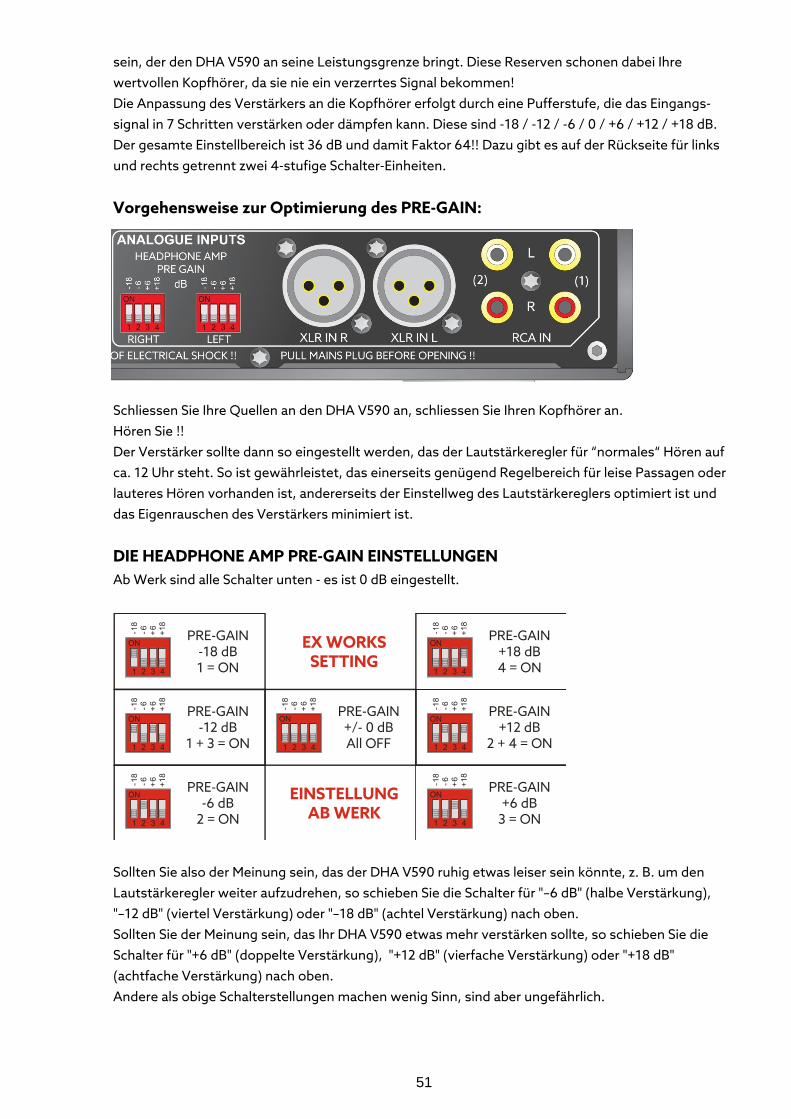
51
sein, der den DHA V590 an seine Leistungsgrenze bringt. Diese Reserven schonen dabei Ihre wertvollen Kopfhörer, da sie nie ein verzerrtes Signal bekommen! Die Anpassung des Verstärkers an die Kopfhörer erfolgt durch eine Pufferstufe, die das Eingangs-signal in 7 Schritten verstärken oder dämpfen kann. Diese sind -18 / -12 / -6 / 0 / +6 / +12 / +18 dB. Der gesamte Einstellbereich ist 36 dB und damit Faktor 64!! Dazu gibt es auf der Rückseite für links und rechts getrennt zwei 4-stufige Schalter-Einheiten.
Vorgehensweise zur Optimierung des PRE-GAIN:
Schliessen Sie Ihre Quellen an den DHA V590 an, schliessen Sie Ihren Kopfhörer an. Hören Sie !! Der Verstärker sollte dann so eingestellt werden, das der Lautstärkeregler für “normales“ Hören auf ca. 12 Uhr steht. So ist gewährleistet, das einerseits genügend Regelbereich für leise Passagen oder lauteres Hören vorhanden ist, andererseits der Einstellweg des Lautstärkereglers optimiert ist und das Eigenrauschen des Verstärkers minimiert ist.
DIE HEADPHONE AMP PRE-GAIN EINSTELLUNGEN Ab Werk sind alle Schalter unten - es ist 0 dB eingestellt.
Sollten Sie also der Meinung sein, das der DHA V590 ruhig etwas leiser sein könnte, z. B. um den Lautstärkeregler weiter aufzudrehen, so schieben Sie die Schalter für "–6 dB" (halbe Verstärkung), "–12 dB" (viertel Verstärkung) oder "–18 dB" (achtel Verstärkung) nach oben. Sollten Sie der Meinung sein, das Ihr DHA V590 etwas mehr verstärken sollte, so schieben Sie die Schalter für "+6 dB" (doppelte Verstärkung), "+12 dB" (vierfache Verstärkung) oder "+18 dB" (achtfache Verstärkung) nach oben. Andere als obige Schalterstellungen machen wenig Sinn, sind aber ungefährlich.
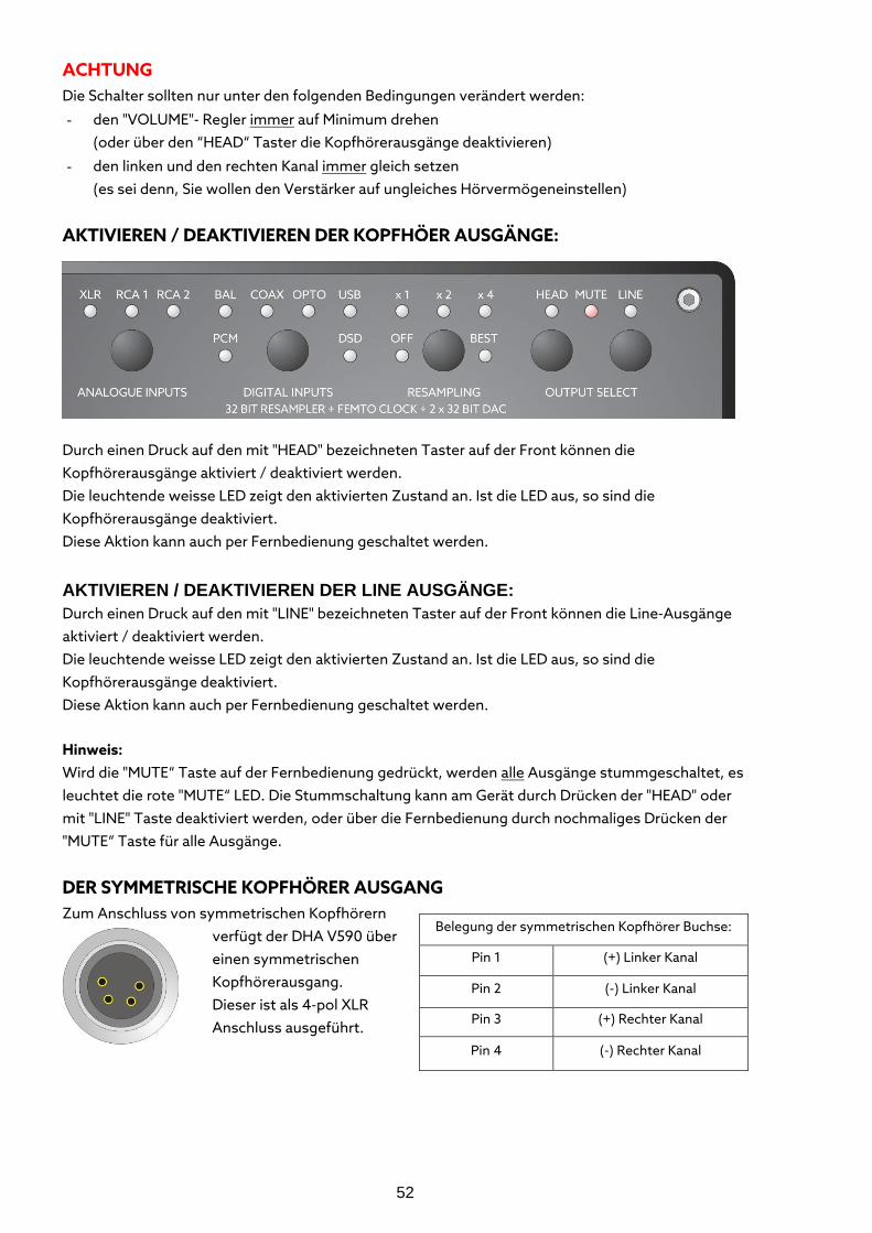
52
ACHTUNG Die Schalter sollten nur unter den folgenden Bedingungen verändert werden:
- den "VOLUME"- Regler immer auf Minimum drehen (oder über den “HEAD“ Taster die Kopfhörerausgänge deaktivieren)
- den linken und den rechten Kanal immer gleich setzen (es sei denn, Sie wollen den Verstärker auf ungleiches Hörvermögeneinstellen)
AKTIVIEREN / DEAKTIVIEREN DER KOPFHÖER AUSGÄNGE:
Durch einen Druck auf den mit "HEAD" bezeichneten Taster auf der Front können die Kopfhörerausgänge aktiviert / deaktiviert werden. Die leuchtende weisse LED zeigt den aktivierten Zustand an. Ist die LED aus, so sind die Kopfhörerausgänge deaktiviert. Diese Aktion kann auch per Fernbedienung geschaltet werden.
AKTIVIEREN / DEAKTIVIEREN DER LINE AUSGÄNGE: Durch einen Druck auf den mit "LINE" bezeichneten Taster auf der Front können die Line-Ausgänge aktiviert / deaktiviert werden. Die leuchtende weisse LED zeigt den aktivierten Zustand an. Ist die LED aus, so sind die Kopfhörerausgänge deaktiviert. Diese Aktion kann auch per Fernbedienung geschaltet werden.
Hinweis: Wird die "MUTE“ Taste auf der Fernbedienung gedrückt, werden alle Ausgänge stummgeschaltet, es leuchtet die rote "MUTE“ LED. Die Stummschaltung kann am Gerät durch Drücken der "HEAD" oder mit "LINE" Taste deaktiviert werden, oder über die Fernbedienung durch nochmaliges Drücken der "MUTE“ Taste für alle Ausgänge.
DER SYMMETRISCHE KOPFHÖRER AUSGANG Zum Anschluss von symmetrischen Kopfhörern
verfügt der DHA V590 über einen symmetrischen Kopfhörerausgang. Dieser ist als 4-pol XLR Anschluss ausgeführt.
Belegung der symmetrischen Kopfhörer Buchse:
Pin 1 (+) Linker Kanal
Pin 2 (-) Linker Kanal
Pin 3 (+) Rechter Kanal
Pin 4 (-) Rechter Kanal
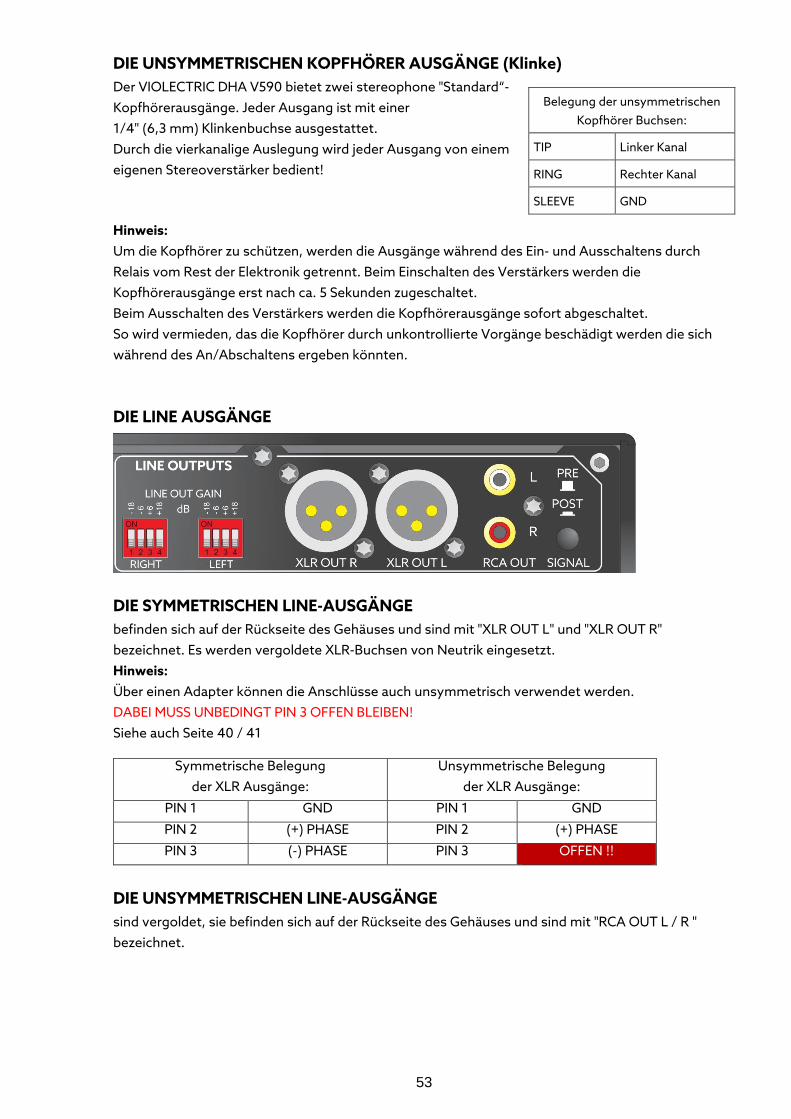
53
DIE UNSYMMETRISCHEN KOPFHÖRER AUSGÄNGE (Klinke) Der VIOLECTRIC DHA V590 bietet zwei stereophone "Standard“- Kopfhörerausgänge. Jeder Ausgang ist mit einer 1/4" (6,3 mm) Klinkenbuchse ausgestattet. Durch die vierkanalige Auslegung wird jeder Ausgang von einem eigenen Stereoverstärker bedient!
Hinweis: Um die Kopfhörer zu schützen, werden die Ausgänge während des Ein- und Ausschaltens durch Relais vom Rest der Elektronik getrennt. Beim Einschalten des Verstärkers werden die Kopfhörerausgänge erst nach ca. 5 Sekunden zugeschaltet. Beim Ausschalten des Verstärkers werden die Kopfhörerausgänge sofort abgeschaltet. So wird vermieden, das die Kopfhörer durch unkontrollierte Vorgänge beschädigt werden die sich während des An/Abschaltens ergeben könnten.
DIE LINE AUSGÄNGE
DIE SYMMETRISCHEN LINE-AUSGÄNGE befinden sich auf der Rückseite des Gehäuses und sind mit "XLR OUT L" und "XLR OUT R" bezeichnet. Es werden vergoldete XLR-Buchsen von Neutrik eingesetzt. Hinweis: Über einen Adapter können die Anschlüsse auch unsymmetrisch verwendet werden. DABEI MUSS UNBEDINGT PIN 3 OFFEN BLEIBEN! Siehe auch Seite 40 / 41
DIE UNSYMMETRISCHEN LINE-AUSGÄNGE
sind vergoldet, sie befinden sich auf der Rückseite des Gehäuses und sind mit "RCA OUT L / R " bezeichnet.
Belegung der unsymmetrischen Kopfhörer Buchsen:
TIP Linker Kanal
RING Rechter Kanal
SLEEVE GND
Symmetrische Belegung der XLR Ausgänge:
Unsymmetrische Belegung der XLR Ausgänge:
PIN 1 GND PIN 1 GND
PIN 2 (+) PHASE PIN 2 (+) PHASE
PIN 3 (-) PHASE PIN 3 OFFEN !!
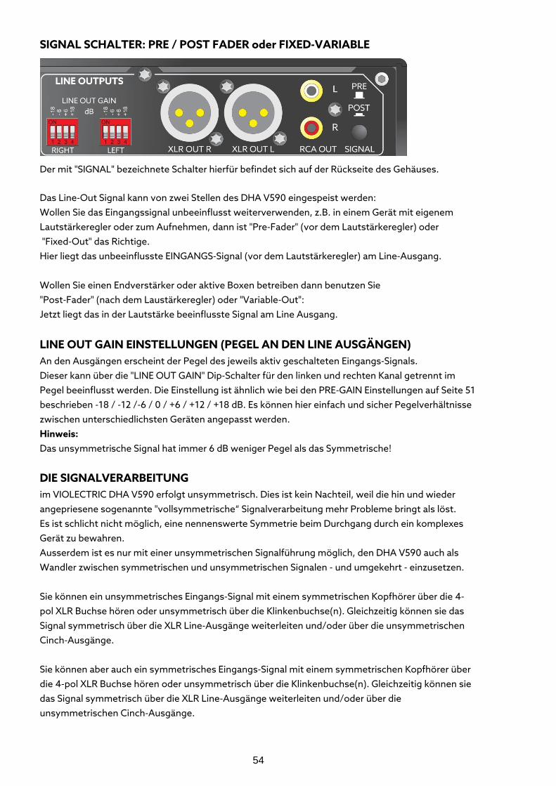
54
SIGNAL SCHALTER: PRE / POST FADER oder FIXED-VARIABLE
Der mit "SIGNAL" bezeichnete Schalter hierfür befindet sich auf der Rückseite des Gehäuses.
Das Line-Out Signal kann von zwei Stellen des DHA V590 eingespeist werden: Wollen Sie das Eingangssignal unbeeinflusst weiterverwenden, z.B. in einem Gerät mit eigenem Lautstärkeregler oder zum Aufnehmen, dann ist "Pre-Fader" (vor dem Lautstärkeregler) oder "Fixed-Out" das Richtige. Hier liegt das unbeeinflusste EINGANGS-Signal (vor dem Lautstärkeregler) am Line-Ausgang. Wollen Sie einen Endverstärker oder aktive Boxen betreiben dann benutzen Sie "Post-Fader" (nach dem Laustärkeregler) oder "Variable-Out": Jetzt liegt das in der Lautstärke beeinflusste Signal am Line Ausgang.
LINE OUT GAIN EINSTELLUNGEN (PEGEL AN DEN LINE AUSGÄNGEN) An den Ausgängen erscheint der Pegel des jeweils aktiv geschalteten Eingangs-Signals. Dieser kann über die "LINE OUT GAIN" Dip-Schalter für den linken und rechten Kanal getrennt im Pegel beeinflusst werden. Die Einstellung ist ähnlich wie bei den PRE-GAIN Einstellungen auf Seite 51 beschrieben -18 / -12 /-6 / 0 / +6 / +12 / +18 dB. Es können hier einfach und sicher Pegelverhältnisse zwischen unterschiedlichsten Geräten angepasst werden. Hinweis: Das unsymmetrische Signal hat immer 6 dB weniger Pegel als das Symmetrische!
DIE SIGNALVERARBEITUNG im VIOLECTRIC DHA V590 erfolgt unsymmetrisch. Dies ist kein Nachteil, weil die hin und wieder angepriesene sogenannte "vollsymmetrische“ Signalverarbeitung mehr Probleme bringt als löst. Es ist schlicht nicht möglich, eine nennenswerte Symmetrie beim Durchgang durch ein komplexes Gerät zu bewahren. Ausserdem ist es nur mit einer unsymmetrischen Signalführung möglich, den DHA V590 auch als Wandler zwischen symmetrischen und unsymmetrischen Signalen - und umgekehrt - einzusetzen. Sie können ein unsymmetrisches Eingangs-Signal mit einem symmetrischen Kopfhörer über die 4-pol XLR Buchse hören oder unsymmetrisch über die Klinkenbuchse(n). Gleichzeitig können sie das Signal symmetrisch über die XLR Line-Ausgänge weiterleiten und/oder über die unsymmetrischen Cinch-Ausgänge. Sie können aber auch ein symmetrisches Eingangs-Signal mit einem symmetrischen Kopfhörer über die 4-pol XLR Buchse hören oder unsymmetrisch über die Klinkenbuchse(n). Gleichzeitig können sie das Signal symmetrisch über die XLR Line-Ausgänge weiterleiten und/oder über die unsymmetrischen Cinch-Ausgänge.
55
FEHLERAUSWERTUNG: Um einen einwandfreien Betrieb zu gewährleisten und Ihre wertvollen Kopfhörer möglichst umfassend zu schützen ist der VIOLECTRIC DHA V590 mit diversen Schutzschaltungen ausgerüstet:
- Die um ca. 5 Sekunden verzögerte Zuschaltung der Kopfhörerbuchsen nach dem Einschalten bewahrt Ihre Kopfhörer vor eventuellen ungesunden Geräuschen aus dem Verstärker. Ebenso erfolgt nach dem Abschalten eine sofortige Trennung der Kopfhörerbuchsen.
- Der Frequenzgang ist auf 5 Hz – 250 kHz (-0,5 dB) begrenzt, um die Kopfhörer vor nicht hörbaren Frequenzen zu schützen.
- Schädliche Gleichspannungen müssen vom Kopfhörer ferngehalten werden. Sollten diese erkannt werden, so werden die Kopfhörerbuchsen getrennt. Dabei leuchtet die "PROTECT" LED rot. Das Fehlerintervall dauert ca. 5 Sekunden, wenn in dieser Zeit die Gleichspannung verschwunden ist, kehrt das Gerät automatisch in den Normalzustand zurück.
- Überlast muss ebenfalls vom Kopfhörer ferngehalten werden. Sollte eine Überlast erkannt werden, so werden die Kopfhörerbuchsen getrennt. Dabei leuchtet die "PROTECT" LED rot. Das Fehlerintervall dauert ca. 5 Sekunden, wenn in dieser Zeit die Überlast verschwunden ist, kehrt das Gerät automatisch in den Normalzustand zurück.
- Alle Fehlermeldungen lassen sich auch durch Aus- und wieder Einschalten zurücksetzen. Wenn die Störung noch da sein sollte, wird das Gerät sofort wieder in den Fehler-Modus schalten.
RESET DES PROZESSORS Die Tasten, die Ablaufsteuerung und die digitale Elektronik im HPA V590 benötigen einen Prozessor.
Wenn mal nichts mehr wie vorgesehen funktionieren sollte können Sie wie folgt das Gerät zurücksetzen: Halten Sie den “ ANALOGUE INPUT “ Taster gedrückt während Sie das Gerät einschalten. Daraufhin leuchten alle Lampen auf. Lassen Sie den “ ANALOGUE INPUT “ Taster los, jetzt ist das Gerät zurückgesetzt.
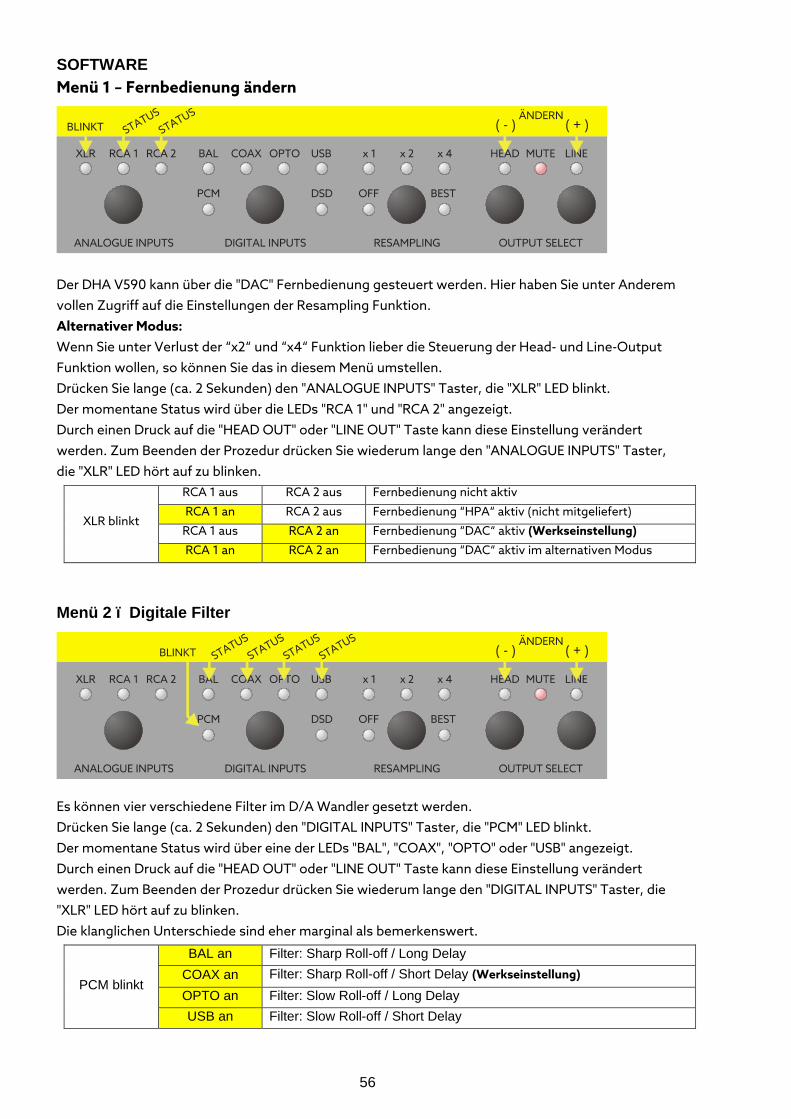
56
SOFTWARE Menü 1 – Fernbedienung ändern
Der DHA V590 kann über die "DAC" Fernbedienung gesteuert werden. Hier haben Sie unter Anderem vollen Zugriff auf die Einstellungen der Resampling Funktion. Alternativer Modus: Wenn Sie unter Verlust der “x2“ und “x4“ Funktion lieber die Steuerung der Head- und Line-Output Funktion wollen, so können Sie das in diesem Menü umstellen. Drücken Sie lange (ca. 2 Sekunden) den "ANALOGUE INPUTS" Taster, die "XLR" LED blinkt. Der momentane Status wird über die LEDs "RCA 1" und "RCA 2" angezeigt. Durch einen Druck auf die "HEAD OUT" oder "LINE OUT" Taste kann diese Einstellung verändert werden. Zum Beenden der Prozedur drücken Sie wiederum lange den "ANALOGUE INPUTS" Taster, die "XLR" LED hört auf zu blinken.
XLR blinkt
RCA 1 aus RCA 2 aus Fernbedienung nicht aktiv
RCA 1 an RCA 2 aus Fernbedienung “HPA“ aktiv (nicht mitgeliefert)
RCA 1 aus RCA 2 an Fernbedienung “DAC“ aktiv (Werkseinstellung)
RCA 1 an RCA 2 an Fernbedienung “DAC“ aktiv im alternativen Modus
Menü 2 – Digitale Filter
Es können vier verschiedene Filter im D/A Wandler gesetzt werden. Drücken Sie lange (ca. 2 Sekunden) den "DIGITAL INPUTS" Taster, die "PCM" LED blinkt. Der momentane Status wird über eine der LEDs "BAL", "COAX", "OPTO" oder "USB" angezeigt. Durch einen Druck auf die "HEAD OUT" oder "LINE OUT" Taste kann diese Einstellung verändert werden. Zum Beenden der Prozedur drücken Sie wiederum lange den "DIGITAL INPUTS" Taster, die "XLR" LED hört auf zu blinken. Die klanglichen Unterschiede sind eher marginal als bemerkenswert.
PCM blinkt
BAL an Filter: Sharp Roll-off / Long Delay COAX an Filter: Sharp Roll-off / Short Delay (Werkseinstellung) OPTO an Filter: Slow Roll-off / Long Delay USB an Filter: Slow Roll-off / Short Delay
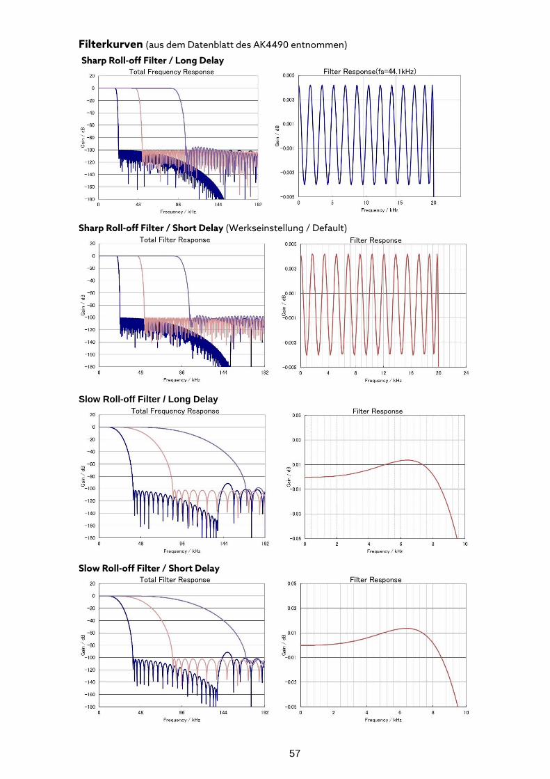
57
Filterkurven (aus dem Datenblatt des AK4490 entnommen) Sharp Roll-off Filter / Long Delay
Sharp Roll-off Filter / Short Delay (Werkseinstellung / Default)
Slow Roll-off Filter / Long Delay Slow Roll-off Filter / Short Delay
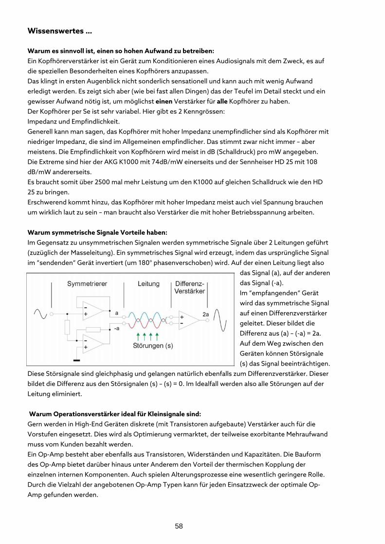
58
Wissenswertes … Warum es sinnvoll ist, einen so hohen Aufwand zu betreiben: Ein Kopfhörerverstärker ist ein Gerät zum Konditionieren eines Audiosignals mit dem Zweck, es auf die speziellen Besonderheiten eines Kopfhörers anzupassen. Das klingt in ersten Augenblick nicht sonderlich sensationell und kann auch mit wenig Aufwand erledigt werden. Es zeigt sich aber (wie bei fast allen Dingen) das der Teufel im Detail steckt und ein gewisser Aufwand nötig ist, um möglichst einen Verstärker für alle Kopfhörer zu haben. Der Kopfhörer per Se ist sehr variabel. Hier gibt es 2 Kenngrössen: Impedanz und Empfindlichkeit. Generell kann man sagen, das Kopfhörer mit hoher Impedanz unempfindlicher sind als Kopfhörer mit niedriger Impedanz, die sind im Allgemeinen empfindlicher. Das stimmt zwar nicht immer – aber meistens. Die Empfindlichkeit von Kopfhörern wird meist in dB (Schalldruck) pro mW angegeben. Die Extreme sind hier der AKG K1000 mit 74dB/mW einerseits und der Sennheiser HD 25 mit 108 dB/mW andererseits. Es braucht somit über 2500 mal mehr Leistung um den K1000 auf gleichen Schalldruck wie den HD 25 zu bringen. Erschwerend kommt hinzu, das Kopfhörer mit hoher Impedanz meist auch viel Spannung brauchen um wirklich laut zu sein – man braucht also Verstärker die mit hoher Betriebsspannung arbeiten. Warum symmetrische Signale Vorteile haben: Im Gegensatz zu unsymmetrischen Signalen werden symmetrische Signale über 2 Leitungen geführt (zuzüglich der Masseleitung). Ein symmetrisches Signal wird erzeugt, indem das ursprüngliche Signal im “sendenden“ Gerät invertiert (um 180° phasenverschoben) wird. Auf der einen Leitung liegt also
das Signal (a), auf der anderen das Signal (-a). Im “empfangenden“ Gerät wird das symmetrische Signal auf einen Differenzverstärker geleitet. Dieser bildet die Differenz aus (a) – (-a) = 2a. Auf dem Weg zwischen den Geräten können Störsignale (s) das Signal beeinträchtigen.
Diese Störsignale sind gleichphasig und gelangen natürlich ebenfalls zum Differenzverstärker. Dieser bildet die Differenz aus den Störsignalen (s) – (s) = 0. Im Idealfall werden also alle Störungen auf der Leitung eliminiert. Warum Operationsverstärker ideal für Kleinsignale sind: Gern werden in High-End Geräten diskrete (mit Transistoren aufgebaute) Verstärker auch für die Vorstufen eingesetzt. Dies wird als Optimierung vermarktet, der teilweise exorbitante Mehraufwand muss vom Kunden bezahlt werden. Ein Op-Amp besteht aber ebenfalls aus Transistoren, Widerständen und Kapazitäten. Die Bauform des Op-Amp bietet darüber hinaus unter Anderem den Vorteil der thermischen Kopplung der einzelnen internen Komponenten. Auch spielen Alterungsprozesse eine wesentlich geringere Rolle. Durch die Vielzahl der angebotenen Op-Amp Typen kann für jeden Einsatzzweck der optimale Op-Amp gefunden werden.
59
Warum PRE-GAIN sinnvoll ist: Zwei extreme Beispiele - die fixe Grösse dabei ist der VIOLECTRIC DHA V590 mit einer Verstärkung von 6 dB (2-fach) bei voll aufgedrehtem Poti. 1. Beispiel: Der (Vor-) Verstärker liefert eine Spannung von 8 Volt, der Kopfhörer braucht aber nur 2 Volt um 100 dB Schalldruck zu erzeugen. Bei aufgedrehtem Poti würde der Verstärker bei +6 dB Verstärkung 16 Volt Spannung liefern, man dürfte also den Lautstärkeregler nur vorsichtig bedienen um keinen Hörschaden davon zu tragen. Weiter sollten laute Störgeräusche am Eingang vermieden werden, weil er die gnadenlos verstärken kann. Durch PRE-GAIN kann man den Eingangspegel um 12 dB (1/4) vermindern, aus 8 Volt Eingangspegel werden 2 Volt. Das wird wieder 2-fach verstärkt, es werden also 4 Volt daraus und man kann jetzt das Lautstärke-Poti fast voll aufdrehen. 2. Beispiel: Der (Vor-) Verstärker liefert eine Spannung von 2 Volt, der Kopfhörer braucht aber 10 Volt um 100 dB Schalldruck zu erzeugen. Bei aufgedrehtem Poti würde der Verstärker bei +6 dB Verstärkung 4 Volt Spannung liefern – viel zu wenig für den Kopfhörer. Durch PRE-GAIN kann man den Eingangspegel um 12 dB (4-fach) erhöhen, aus 2 Volt Eingangspegel werden 8 Volt. Diese werden wieder 2-fach verstärkt, es werden also 12 Volt daraus. Damit ist der Kopfhörer voll ausgesteuert! Warum es sinnvoll ist, den Frequenzgang zu begrenzen Töne sind elektrische Wechselspannungen. Hören kann man diese als junger Mensch von ca. 20 Hz bis 20.000 Hz. Je älter der Mensch, desto weniger hört er vor allen Dingen die hohen Frequenzen. Um Hör-Frequenzen möglichst gut zu übertragen muss der Frequenzgang eines Verstärkers möglichst breit und möglichst glatt sein. Nach unten ist diese Grenze durch die Gleichspannung gesetzt, tiefer geht es nicht. Nach oben kann sich die Grenze grundsätzlich in (fast) jeder beliebigen Höhe befinden, jedoch wird das Gerät dadurch auch empfindlich für elektromagnetische Einstrahlungen. Die hört man zwar erstmal nicht, sie mischen sich aber mit den Nutzfrequenzen und dann können sie hörbar werden. Ein beliebig offener Frequenzgang zeugt also nicht unbedingt von bemerkenswerter Ingenieursleistung - sondern eher von Verantwortungslosigkeit. Warum eine gute Lautstärkeregelung wichtig ist. Ein übliches Lautstärke Poti ist ein mechanisches Stellglied, das es im Weltmarkt beliebig günstig gibt. Zwar wird es inzwischen oft durch elektronische Schaltungen ersetzt, die haben jedoch bezüglich Dynamik, Rauschen und Verzerrungen deutliche Nachteile. Widerstandsbahnen aus Leitplastik, hochwertige “Multitap“-Schleifer und getrennte Kammern für die einzelnen Sektionen sind für hochwertige Anwendungen wünschenswert. Um einen problemlosen Betrieb über Jahre sicher zu stellen, ist eine hohe Qualität unabdingbar. Da der Markt für richtig gute Potis klein ist, haben Hersteller wie Noble oder Panasonic nichts mehr im Angebot. Deshalb ist mit die Spitze des Machbaren das RK27 Poti von Alps, was auch im “Standard“ DHA V590 verwendet wird. Über die verschiedenen Varianten zur Lautstärkeeinstellung. Der DHA V590 PRO bietet eine aufwendigere Lautstärkeeinstellung: Hier wird über Reed-Relais eine 256-stufige Steuerung der Lautstärke realisiert. Dies verhindert die üblichen Probleme, die mechanische Potentiometer haben können: Kanalungleichheiten, Übersprechen, Kratzen. Das Reed-Relais schaltet gegenüber herkömmlichen Relais seine Kontakte in einer versiegelten Schutzgas Atmosphäre. Die 256-fache Relaissteuerung wird realisiert mit 8 Relais pro Kanal, weil 28 = 256 ist. Jeder Schritt ist zu 0,4 dB definiert, sodass der Regelbereich über 100 dB beträgt.
60
Die Relais schalten rauscharme Präzisionswiderständen mit einer Toleranz von 1% oder 0,1%. Auf diese Weise wird beste Kanalgleichheit und geringstes Übersprechen erzielt – und kratzen werden die Relais auch nicht. Um das gleiche Drehgefühl wie bei guten "gebräuchlichen“ Lösungen zu erreichen, wird ein Motorpoti verwendet. Durch das Poti wird aber nur ein Stellwert generiert, dieser wird über einen A/D Wandler in die digitale Ebene transferiert und einem Microcontroller zugeführt, der die Relais steuert. Warum ein niedriger Innenwiderstand wichtig ist Jedes elektrodynamische System erzeugt nach einer Wirkung eine Rückwirkung. Wenn die Schwingspule eines Kopfhörers durch den Verstärker ausgelenkt wird, entsteht ein (Fehl)-Strom, wenn sie wieder in ihre Ausgangslage zurückfällt. Dieser Strom muss so gut wie möglich unterdrückt werden da sich ansonsten Wechselwirkungen der Impedanzen des Verstärkers und des Kopfhörers ergeben. Diese äussern sich gern in einer Resonanz bei tiefen Frequenzen und damit einem verstärkten Bass. Der ist aber nicht echt und damit trocken und knackig, sondern resonanzbedingt eher dröhnend und unspezifisch. Um obige Probleme nachhaltig in den Griff zu bekommen, muss die Ausgangsimpedanz des Verstärkers so niedrig wie möglich ist. Dann ist nämlich seine Stromaufnahmefähigkeit so hoch wie möglich. Der Innenwiderstand kann auch als Dämpfungsfaktor beschrieben werden und ist nichts anderes als das Verhältnis des Innenwiderstandes eines Verstärkers zu einer gegebenen Last. Da technische Vorschriften fehlen, definieren wir die Last (Impedanz der Schwingspule) mit 50 Ohm. Bei einer Ausgangsimpedanz des DHA V590 von < 0,3 Ohm im symmetrischen Betrieb und von < 0,15 Ohm im unsymmetrischen Betrieb ergeben sich Dämpfungsfaktoren von 160 (symmetrisch) und 320 (unsymmetrisch). Allgemeine Empfehlungen gehen davon aus, das er Innenwiderstand eines Verstärkers weniger als 5 % der Kopfhörerimpedanz betragen sollte = Dämpfungsfaktor > 20. Warum eine hohe Betriebsspannung wichtig ist: Ein Kopfhörer braucht zwar nicht viel Leistung, aus P = U2 / R ergibt sich jedoch, das bei gegebenem (Last-) Widerstand die Spannung quadratisch in die Leistung eingeht. Je hochohmiger ein Kopfhörer ist, desto mehr Spannung braucht er also. Dies hat nur bedingt mit der absolut erzielbaren Lautstärke zu tun: Musik lebt von schnellen Transienten, die hohe Anforderungen an die Übertragungstechnik stellen. Und so kann ein schneller Impuls einen „gewöhnlichen“ Verstärker mit +/- 15 Volt Betriebsspannung (95 % aller Kopfhörerverstärker im Markt haben diese oder geringere Betriebsspannungen) leicht an sein Limit bringen. Denn die maximal erzeugbare Amplitude ist mit einer Betriebsspannung von + / - 15 Volt maximal 10 V eff. Durch unsere deutlich höhere Betriebsspannung von 25 V im Zusammenhang mit der symmetrischen Ansteuerung der Kopfhörer gewinnen Sie eine wesentlich höhere Aussteuerungsfähigkeit, nämlich über 20 Veff.
Warum wir unsere Endstufe so und nicht anders bauen. Sie ist mit Transistoren aufgebaut und wird mit +/- 25 Volt betrieben, weil es an dieser Stelle sinnvoll ist. Wirkliche Leistung ist hier jedoch nicht gefragt. Eine Endstufe besteht aus 8 Transistoren, viermal Kleintransistoren und vier schnelle Video-Leistungstransistoren. Angesteuert wird alles von einem Op-Amp, er arbeitet nichtinvertierend, die Verstärkung ist auf 0 dB (1-fach) eingestellt. Da im symmetrischen Betrieb je zwei Endstufen pro Kanal im Push-Pull Betrieb laufen ist die Gesamt-verstärkung in diesem Fall +6 dB.
61
Für hochohmige Kopfhörer stellt die Endstufe im symmetrischen Betrieb eine sehr hohe Spannung bereit (> 21 Veff), für niederohmige Kopfhörer gibt es Leistung satt (> 6 W an 50 Ohm). Dabei bewegen sich Rauschen, Klirrfaktor und Dynamik im Grenzbereich des physikalisch Möglichen. Warum ein Relais beim Ein/Ausschalten sinnvoll sind: Jeder Verstärker verursacht während des Ein- oder Ausschaltvorgangs Störungen. Diese können die angeschlossenen Kopfhörer beschädigen. Das Relais trennt den Kopfhörer (und schützt ihn somit) von der Geräteelektronik, solange keine klar definierten Verhältnisse zu erwarten sind. Entsorgung Entsorgung von gebrauchten elektrischen und elektronischen Geräten (anzuwenden in den Ländern der Europäischen Union und anderen europäischen Ländern mit einem separaten Sammelsystem für
diese Geräte). Das Symbol auf dem Produkt oder seiner Verpackung weist darauf hin, dass dieses Produkt nicht als normaler Haushaltsabfall zu behandeln ist, sondern an einer Annahmestelle für das Recycling von elektrischen und elektronischen Geräten abgegeben werden muss. Durch Ihren Beitrag zum korrekten Entsorgen dieses Produkts schützen Sie die Umwelt und die Gesundheit Ihrer Mitmenschen. Umwelt und Gesundheit werden durch falsches Entsorgen gefährdet.
Materialrecycling hilft, den Verbrauch von Rohstoffen zu verringern. Weitere Informationen zum Recycling dieses Produkts erhalten Sie bei Ihrer Gemeindeverwaltung, den kommunalen Entsorgungsbetrieben oder dem Geschäft, in dem Sie das Produkt gekauft haben.
TECHNISCHE DATEN VIOLECTRIC DHA V590 Alle Werte RMS unbew., 20 Hz - 20 kHz, Pre-Gain auf 0 dB
Eingangsparameter Analog Eingänge (stereo, analog): 1 x XLR female, balanced, 2 x RCA, unbalanced Max. Eingangsspannung: + 21 dBu Eingangsimpedanz: 10 kohm Eingangsparameter Digital Eingänge (stereo, digital) 1 x Balanced, XLR, PCM bis 24 Bit, 192 kHz 1 x Unbalanced, Coaxial, PCM bis 24 Bit, 192 kHz 1 x optisch, Tos-Link, PCM bis 24 Bit, 96 kHz 1 x USB, PCM bis 32 Bit, 384 kHZ / DSD bis 256 Line Out Parameter Line Ausgänge (stereo, analog): 1 x XLR male, balanced 1 x RCA unbalanced Line-Out Gain: -18 / -12 / -6 / 0 / +6 / +12 / +18 dBr Max. Ausgangsspannung: + 21 dBu Ausgangsimpedanz: < 1 Ohm
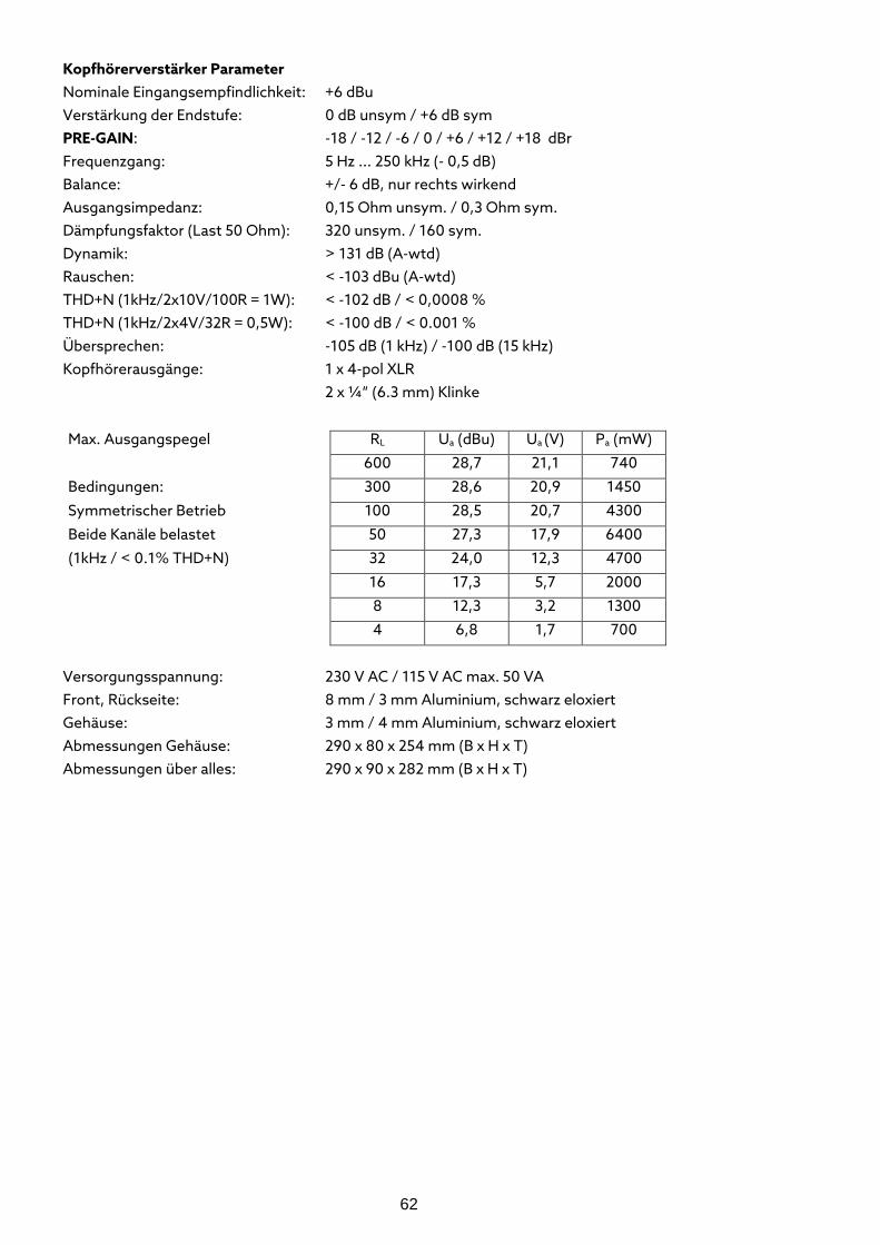
62
Kopfhörerverstärker Parameter Nominale Eingangsempfindlichkeit: +6 dBu Verstärkung der Endstufe: 0 dB unsym / +6 dB sym PRE-GAIN: -18 / -12 / -6 / 0 / +6 / +12 / +18 dBr Frequenzgang: 5 Hz ... 250 kHz (- 0,5 dB) Balance: +/- 6 dB, nur rechts wirkend Ausgangsimpedanz: 0,15 Ohm unsym. / 0,3 Ohm sym. Dämpfungsfaktor (Last 50 Ohm): 320 unsym. / 160 sym. Dynamik: > 131 dB (A-wtd) Rauschen: < -103 dBu (A-wtd) THD+N (1kHz/2x10V/100R = 1W): < -102 dB / < 0,0008 % THD+N (1kHz/2x4V/32R = 0,5W): < -100 dB / < 0.001 % Übersprechen: -105 dB (1 kHz) / -100 dB (15 kHz) Kopfhörerausgänge: 1 x 4-pol XLR 2 x ¼“ (6.3 mm) Klinke
Max. Ausgangspegel RL Ua (dBu) Ua (V) Pa (mW)
600 28,7 21,1 740
Bedingungen: 300 28,6 20,9 1450
Symmetrischer Betrieb 100 28,5 20,7 4300
Beide Kanäle belastet 50 27,3 17,9 6400
(1kHz / < 0.1% THD+N) 32 24,0 12,3 4700
16 17,3 5,7 2000
8 12,3 3,2 1300
4 6,8 1,7 700
Versorgungsspannung: 230 V AC / 115 V AC max. 50 VA Front, Rückseite: 8 mm / 3 mm Aluminium, schwarz eloxiert Gehäuse: 3 mm / 4 mm Aluminium, schwarz eloxiert Abmessungen Gehäuse: 290 x 80 x 254 mm (B x H x T) Abmessungen über alles: 290 x 90 x 282 mm (B x H x T)
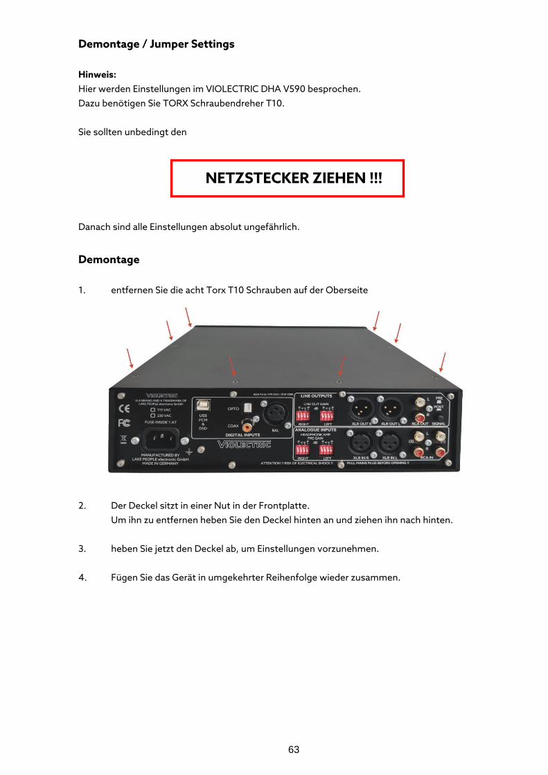
63
Demontage / Jumper Settings Hinweis: Hier werden Einstellungen im VIOLECTRIC DHA V590 besprochen. Dazu benötigen Sie TORX Schraubendreher T10. Sie sollten unbedingt den
NETZSTECKER ZIEHEN !!! Danach sind alle Einstellungen absolut ungefährlich.
Demontage 1. entfernen Sie die acht Torx T10 Schrauben auf der Oberseite 2. Der Deckel sitzt in einer Nut in der Frontplatte. Um ihn zu entfernen heben Sie den Deckel hinten an und ziehen ihn nach hinten. 3. heben Sie jetzt den Deckel ab, um Einstellungen vorzunehmen. 4. Fügen Sie das Gerät in umgekehrter Reihenfolge wieder zusammen.
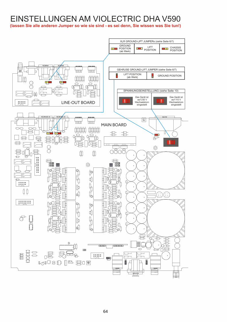
64
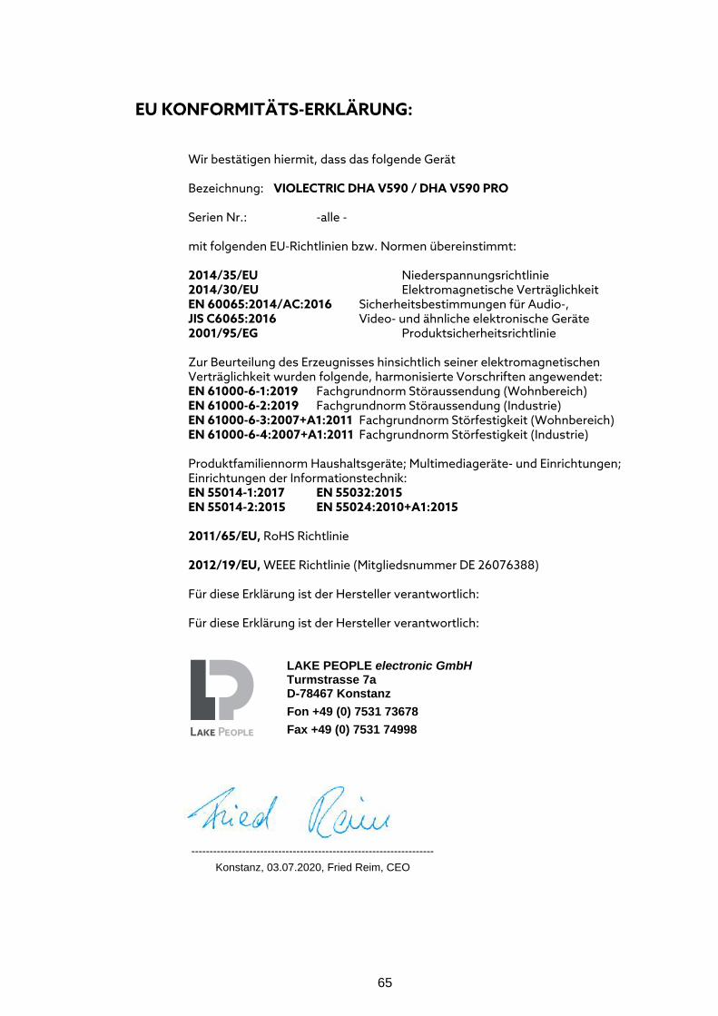
65
EU KONFORMITÄTS-ERKLÄRUNG:
Wir bestätigen hiermit, dass das folgende Gerät Bezeichnung: VIOLECTRIC DHA V590 / DHA V590 PRO Serien Nr.: -alle - mit folgenden EU-Richtlinien bzw. Normen übereinstimmt: 2014/35/EU Niederspannungsrichtlinie 2014/30/EU Elektromagnetische Verträglichkeit EN 60065:2014/AC:2016 Sicherheitsbestimmungen für Audio-, JIS C6065:2016 Video- und ähnliche elektronische Geräte 2001/95/EG Produktsicherheitsrichtlinie Zur Beurteilung des Erzeugnisses hinsichtlich seiner elektromagnetischen Verträglichkeit wurden folgende, harmonisierte Vorschriften angewendet: EN 61000-6-1:2019 Fachgrundnorm Störaussendung (Wohnbereich) EN 61000-6-2:2019 Fachgrundnorm Störaussendung (Industrie) EN 61000-6-3:2007+A1:2011 Fachgrundnorm Störfestigkeit (Wohnbereich) EN 61000-6-4:2007+A1:2011 Fachgrundnorm Störfestigkeit (Industrie) Produktfamiliennorm Haushaltsgeräte; Multimediageräte- und Einrichtungen; Einrichtungen der Informationstechnik: EN 55014-1:2017 EN 55032:2015 EN 55014-2:2015 EN 55024:2010+A1:2015 2011/65/EU, RoHS Richtlinie 2012/19/EU, WEEE Richtlinie (Mitgliedsnummer DE 26076388) Für diese Erklärung ist der Hersteller verantwortlich: Für diese Erklärung ist der Hersteller verantwortlich:
------------------------------------------------------------------- Konstanz, 03.07.2020, Fried Reim, CEO
LAKE PEOPLE electronic GmbH Turmstrasse 7a D-78467 Konstanz Fon +49 (0) 7531 73678 Fax +49 (0) 7531 74998
66
GARANTIE Seit 1986 bauen wir anspruchsvolle Geräte für anspruchsvolle Kunden. Von Anfang an bemühen wir uns, durch geeignete Massnahmen wie hochwertige Bauteile oder mehrfach überwachte Produktionsschritte Fehler gar nicht erst aufkommen zu lassen. Das gelingt uns auch meistens und hat mit zu unserem guten Ruf beigetragen. Trotz aller Sorgfalt können hin und wieder Fehler auftauchen, die den einwandfreien Betrieb Ihres Gerätes beeinträchtigen. In diesem Fall greift unsere 5-jährige Garantie ohne Wenn und Aber!! Natürlich stehen wir unseren Kunden auch nach Ablauf der Garantie meist sehr kulant oder zu geringen Kosten zur Verfügung. Im Fall des Falles senden Sie bitte Ihr Gerät an folgende Adresse: Lake People electronic GmbH Fon +49 (0) 7531 73678 Turmstrasse 7a Fax +49 (0) 7531 74998 78467 Konstanz E-Mail [email protected] Ihr Garantieanspruch beginnt mit dem Datum des Verkaufs, eingetragen auf Ihrem Kaufbeleg. Sollte etwas mehr Zeit verstrichen sein, so ist das kein Drama. Legen Sie deshalb den Kaufbeleg oder eine Kopie des Kaufbelegs bei. Legen Sie weiterhin eine kurze Fehlerbeschreibung bei und vergessen Sie nicht Ihre korrekte Adresse für die Rücksendung Achten Sie auf eine sichere Verpackung, verwenden Sie am besten die Originalverpackung. Bitte beachten Sie, das unfreie Sendungen nicht angenommen werden können ! Wir bemühen uns um eine zügige Reparatur. Die Rücksendung erfolgt im Garantiefall frei an die mitgeteilte Adresse. Tragen Sie zur Sicherheit hier die Seriennummer und das Kaufdatum ein: Seriennummer Kaufdatum