Embed Size (px)
Citation preview

HD2016 LED Control Card Operation manual
1 / 43
Document content HD2016 LED Control Card Operation manual
version English V1.0
Page number range 1-42
HD2016 LED Display Controller
Operation Manual

HD2016 LED Control Card Operation manual
2 / 43
CONTENTS
APPENDIX 1: CONTROL CARD CATALOGUE ................................................................... 错误!未定义书签。
THE APPENDIX 1.1: CONTROL CARD SELECTION...........................................................................................................4
CHAPTER ONE: INTRODUCTION ...................................................................................... 错误!未定义书签。
1.1: FUNCTION FEATURE .....................................................................................................错误!未定义书签。
1.2: OPERATING ENVIRONMENT...........................................................................................错误!未定义书签。
CHAPTER TWO: INSTALL AND UNINSTALL ...........................................................................................................6
2.1: INSTALL .......................................................................................................................错误!未定义书签。
2.2: UNINSTALL...................................................................................................................错误!未定义书签。
CHAPTER THREE: TOOL USING DETAILS INSTRUCTIONS ............................................ 错误!未定义书签。
3.1: THE SOFTWARE MAIN INTERFACE ..................................................................................错误!未定义书签。
3.2: TITLE BAR ....................................................................................................................错误!未定义书签。
3.3: MENU BAR ...................................................................................................................错误!未定义书签。
3.3.1: file menu .........................................................................................................错误!未定义书签。
3.3.2: setting menu ..................................................................................................错误!未定义书签。
3.3.3: operation menu ................................................................................................................................ 14
3.3.4: tools .................................................................................................................................................... 16
3.3.5: language menu: .............................................................................................................................. 16
3.3.6: help menu .......................................................................................................................................... 16
3.4: TOOLS BAR...................................................................................................................................................... 16
3.5: SIMULATING DISPLAY SCREEN............................................................................................................................17
3.6: DISPLAY PROPERTIES BAR .................................................................................................................................17
3.7: INSTRUCTIONS OF REMOTE CONTROL ............................................................................................................... 18
3.8:SMART SETTING METHOD ................................................................................................................................. 19
3.9: THE CROSS SCREEN SETTING WAY ..................................................................................................................... 22
CHAPTER FOUR: CREATING STEPS OF SCREEN PROGRAM............................................................................ 23
4.1: NEW SCREEN FILE(THE FIRST LEVEL CONTENT) .................................................................................................. 23
4.2: NEW PROGRAM(THE SECOND LEVEL CONTENT,MAX SUPPORT 1000 PROGRAMS) ............................................... 24
4.3: NEW PARTITION(THE THIRD LEVEL CONTENT,MAX SUPPORT TO SET 20 PARTITION)...........错误!未定义书签。
4.4: FINISH MAKING PROGRAM............................................................................................错误!未定义书签。
CHAPTER FIVE: HOW TO DISPLAY DIFFERENT CONTENTS ......................................... 错误!未定义书签。
5.1: TEXT PROGRAM............................................................................................................错误!未定义书签。
5.2: IMAGE PROGRAM.........................................................................................................错误!未定义书签。
5.3: ANIMATION WORD PROGRAM.......................................................................................错误!未定义书签。
5.4: EXCEL PROGRAM..........................................................................................................错误!未定义书签。
5.5: TIME PROGRAM(CALENDAR TIME AND DIAL) .................................................................错误!未定义书签。
5.6: TIME COUNT ON/DOWN PROGRAM...............................................................................错误!未定义书签。
5.7: COUNT NUMBER PROGRAM ..........................................................................................错误!未定义书签。
5.8: TEMPERATURE OR TEMPERATURE AND HUMIDITY PROGRAM(NEED BUY EXTRA SENSOR) ..错误!未定义书签。

HD2016 LED Control Card Operation manual
3 / 43
5.9: LUNAR CALENDAR ........................................................................................................错误!未定义书签。
CHAPTER SIX: COMMUNICATION SETTINGS................................................................. 错误!未定义书签。
6.1: SERIAL LINE INSTRUCTIONS ...........................................................................................错误!未定义书签。
6.2: COMMUNICATION SETTINGS (SERIAL PORT) ...................................................................错误!未定义书签。
6.2.1: 232 communication ...................................................................................错误!未定义书签。
6.2.2: 485 communication ...................................................................................错误!未定义书签。
6.3: ETHERNET CABLE INSTRUCTION .....................................................................................错误!未定义书签。
6.4: COMMUNICATION SETTINGS (SERIAL PORT) ...................................................................错误!未定义书签。
6.4.1: single LAN network card (HD-E63) Communications..............................错误!未定义书签。
6.4.2: multiple LAN network cards (several HD -E63) Communications ..........错误!未定义书签。
6.5:COMMUNICATION SETTINGS (WIFI CARD) ........................................................................................................ 35
6.5.1:single WIFI card connection ............................................................................................................ 35
6.5.2:multiple wifi card connection ...........................................................................................................37
6.6:U-DISK CARD INSTRUCTIONS ..............................................................................................................................37
APENDIX 2: COMMON SETTINGS IN USE PROCESS ........................................................................................ 39
APENDIX 2.1: HOW TO REMOTE UPGRADE CONTROL CAR.......................................................................................... 39
APENDIX 2.2: HOW TO MAKE FACTORY DATA RESET................................................................................................... 40
APENDIX 2.3: HOW TO TEST LED DISPLAY BY CONTROLLER.....................................................错误!未定义书签。
APENDIX 2.4: HOW TO TIMING BOOT AND SHUTDOWN LED DISPLAY .......................................................................... 40
APENDIX 2.5: HOW TO SET TIME TO PLAY ................................................................................................................. 40
APENDIX 2.6: HOW TO SET TEXT SUBTITLE MOTIONLESS .......................................................................................... 40
APENDIX 2.7: HOW TO SET TEXT SUBTITLE CONTINUOUS MOVING AND UNINTERRUPTED .......................................... 41
APENDIX 2.8: TEMPERATURE AND HUMIDITY OPERATION INSTRUCTION ..................................................................... 41

HD2016 LED Control Card Operation manual
4 / 43
Appendix 1: Control card catalogue
Appendix 1.1: Control card selection
Control card model No, control range, and hub port type
Model No Communication single color Dual color Tri color Hub port
HD-U6A
USB port
320*32 160*32 / 2 HUB12
HD-U60
512*32 256*32 / 1HUB08,2HUB12
HD-U6B
1024 *48 512*48 / 3HUB12
HD-U61 1024*32 512*32 / 1HUB08,2HUB12
HD-U62
512*64 256*64 320*32 2HUB08,4HUB12
HD-U63
512*128 256*128 320*64 4HUB08,8HUB12
HD-U64 512*256 256*256 320*128 1 of 50PIN
HD-S61 USB+ Serial port 1024*32 512*32 / 1HUB08,2HUB12
HD-S62 1024*64 512*64 672*32 2HUB08,4HUB12
HD-S63 1024*128 512*128 672*64 4HUB08,8HUB12
HD-S64 1024*256 512*256 672*128 1 of 50PIN
HD-S65 1024*512 512*512 672*256 2 of 50PIN
HD-S66 2048*512 1024*512 1344*256 2 of 50PIN
HD-E61
USB+LAN Port
1024*32 512*32 / 1HUB08,2HUB12
HD-E62 1024*64 512*64 672*32 2HUB08,4HUB12
HD-E63 1024*128 512*128 672*64 4HUB08,8HUB12
HD-E64 1024*256 512*256 672*128 1 of 50PIN
HD-E65 1024*512 512*512 672*256 2 of 50PIN
HD-E66 2048*512 1024*512 1344*256 2 of 50PIN
HD-W61
USB+WIFI Port 1024*32 512*32 / 1HUB08,2HUB12
HD-W62 1024*64 512*64 672*32 2HUB08,4HUB12
HD-W63 1024*128 512*128 672*64 4HUB08,8HUB12
HD-W64 1024*256 512*256 672*128 1 of 50PIN

HD2016 LED Control Card Operation manual
5 / 43
Chapter One: Introduction
1.1: Function feature
HD2016 control system is a creative and drastic changes which is made by Huidu
technology Co.,Ltd .To offer customer easy and stable selection. we integrate part of
repetitive controller, the control range become more flexible, the price become more
effective, which are enough to meet market trend of higher, longer, multiple strip
screens.
The software whole interface kept the style of simple operation, strong function,
easy to learn and use, support image-text(Excel、JGP、BMP、GIF、SWF、video、text、
animation word etc.)、Text、animation word、Excel、time、timer(countdown
/up/button countdown / up)、count、lunar calendar、Temperature and humidity etc,
can support serials port(including 232 and 485)、Ethernet port、WIFI、U-disk etc.
Multiple control communication, can meet the application of different situations.
Main advantages:
1. Support gradation (control range would be affected);
2. Support layer overlay, areas overlap;
3. Add WordArt, animation characters;
4. Full support smart settings, support for all modules (U disk card using common
settings);
5. Support a variety of custom combinations of effects;
6. Support Subdivision background;
7. Add button chronograph (cyclic time), button count;
8. Support Live Partition (secondary development);
9. The higher brightness and faster speed left. Higher refresh rates;
10. The new text rotation, supports 90°, 180°and 270°rotation;
11. The increase in receivables function, parameter lock screen function;
12. Support Temp, humidity, brightness, remote control and can choose to play 1-999
programs;
13. Support 485 and 232;
14. Support direct connection, LAN, inter-network multi-connection, the device can
be found;

HD2016 LED Control Card Operation manual
6 / 43
15. Support WIFI wireless connection,no wiring, can also insert to router to cluster
manage;
16. Support group management.
1.2: operating environment
Operation system: Chinese and English
Software support all languages
Windows 2000/XP/Win7/Win8/Win10 etc.
Chapter two: Install and uninstall
2.1: Install
HD2016 simple install process, operation as below: find the file
HD2016_V2.0.1.1907.***.zip in the CD. Unzip it and double click
HD2016_V2.0.1.1907.***.exe. You will enter the software installation guide as below

HD2016 LED Control Card Operation manual
7 / 43
Follow guide tips (next step) to finish installation
Note: if the operated system is Win7 or Vista, please put the installation path to
non-system disk
After HD2016 software finished installation ,in【start】→【program】can find “HD2016”
program group, then click HD2016 to run it. As well, you can click shortcut of
HD2016.exe on the desktop to access software.
2.2: uninstall
HD2016 software package offer full uninstall function, user can easily delete all files,
programs and shortcut in the “HD2016”folder.User can select uninstall HD2016 in
【start】→【program】→HD2016 program group to finish uninstall.
Chapter three: TOOL DETAILS INSTRUCTIONS
3.1: The software main interface
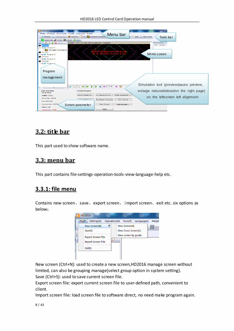
Open ”HD2016” software main interface as below:
Group manage screens.
The toolbar can be divided into two columns, can also be shown as one row. Info window can show the command status if send successfully, also can show
current online
Device.
HD2016 LED Control Card Operation manual
8 / 43
.
3.2: title bar
This part used to show software name.
3.3: menu bar
This part contains file-settings-operation-tools-view-language-help etc.
3.3.1: file menu
Contains new screen、save、export screen、import screen、exit etc. six options as
below:
New screen (Ctrl+N): used to create a new screen,HD2016 manage screen without
limited, can also be grouping manage(select group option in system setting).
Save (Ctrl+S): used to save current screen file.
Export screen file: export current screen file to user-defined path, convenient to
client.
Import screen file: load screen file to software direct, no need make program again.
Menu bar Tools bar
Mimic screen
Simulation tool (preview/pause preview,
enlarge reduced/about/on the right page)
on the leftscreen left alignment
Program
management
Screen parameter

HD2016 LED Control Card Operation manual
9 / 43
Exit: close HD2016 software.
3.3.2: setting menu
Contains screen parameter settings、communication settings、system settings、RF
setting, see as below:
1.Screen parameter settings: used to bind parameter of device and screen, as below:
1).First step, if control card displays normally, it just need set screen’s width and height pixel,
color and gray level,
2).If display not normally, then it need go to hardware setting. Second step, hardware setting,
please choose default common smart setting for common screen.
For example: P10 single color, just select below photo of A6 then it is ok. And others no need
change.
Note: For abnormal led module, select Additional –smart setting .
(For smart setting: it need find the device first , U-disk controller can’t smart setting)

HD2016 LED Control Card Operation manual
10 / 43
Button setting in the interface of hardware setting, used to set four buttons’ function, as below:
2. Communication setting: used to amend the way when connecting multiple cards.
1).Ethernet:
①The defaulted way is connection 1PCS card .Meaning only one card connected with
computer, no need any IP setting, just need normal LAN cable connection and find
the device.
②.when not select “Direct connection mode”, it is suitable for condition when controller and main operated PC are not at the same network segment, it need add
the IP address of controller network segment to the software. Operation as below.
After added, then you can find the controller in 192.168.3.*

HD2016 LED Control Card Operation manual
11 / 43
2). COM Port: used for case of connecting multiple 485 serials port controllers. when
first time connecting 485 serials port controller, user only can connect it to PC one
piece by one piece, click the “search” as photo shows below, store the ID in the
current interface or manual add known ID ,when all Card’s ID show in the current
interface, pls connect all cards’ 485 port well.
3).wifi: Used connect wifi signal of controller ,automatically default input password
88888888 ,no need manual input, as below shows:

HD2016 LED Control Card Operation manual
12 / 43
4).RF: Only used for the case of controller added RF module, to search controller ID.
5). DHCP: when multiple controllers connected to the Switch, user do not need set
card IP address. Use DHCP, software will distribute IP address for controllers
automatically, see picture as below: software distribute IP address
192.168.4.100-192.168.4.200 to controllers. Only use on the case of controller
connected to Switch, no router.

HD2016 LED Control Card Operation manual
13 / 43
6). Advanced setting. Advanced setting interface is used to set if need find 4th
generation card (After found 4th generation card, just upgrade firmware), Type one to
type four is LAN card connection way. The software Default setting is Type one.
3. System setting: setting system parameter (suggest not modified)
Add new function: lock screen, it can choose which parameter can’t modification.

HD2016 LED Control Card Operation manual
14 / 43
4.RF setting:Setting RF module sequence number、ID、data、speed and order.
3.3.3 Operation menu
1).Device manage:modify all the found device name, modify Ethernet card IP address, and manage device clear display data、 timing setting、 brightness setting、
timer switch、 display screen testing、 switch、restart display screen.
.

HD2016 LED Control Card Operation manual
15 / 43
2). Multiple sending: Sending multiple led screen files. And have two modes:
multiple -screen mode and copy mode. All found device can be used ,including
Ethernet port card、serial port card、Wifi card .
①Multiple-screen mode: In Setting-screen parameter setting-Device name, and
must select device name, and each screen file binding a device.
②Copy mode: Selected the screen file that need send, and sending this screen file to
all found devices.
3). Time settings: setting led control card time, can be system time, also can try past
or future time.
4). Brightness setting: Having 3 mode. custom, automatic adjustment and by time
period regulation
5).Timer switch: Setting time with PC synchronous or setting time by different.
6).Boot Animation: Showing image when opening the display. Selected Enable, and
select image (bmp、jpg、png ) after download file click “sending”, or export file to U-disk.
7).Display screen testing: software test led display
8). Clear display data: Clear control card program
9).U-disk import screen parameter: When display showing normal--and insert
U-disk to PC- -The U-disk can read screen parameter. If insert U-disk to PC-- click “import parameter from U-disk ”---then the current
parameter import to software HD2016.
10).Update Firmware: Used for updated firmware

HD2016 LED Control Card Operation manual
16 / 43
3.3.4 Tools
Including Notepad、calculator、drawing、 network testing、 the local IP Settings,
Animated characters background、 info window、 Program appearance.
3.3.5Language menu:
Including 21 kinds operation interface language Arabic, Bulgarian、 Chinese
simplified、English、French、 German、Hindi、Iranian、 Japanese、 Korean、
Mongolian、 polish、 Portuguese、 romanian、 Russian、 Serbian、Spanish、 Thai、
Chinese traditional、Turkish、Vietnamese and so on.
3.3.6 Help menu :
Checking HD2016 software version and updating new version software synchronous
3.4 Toolbar
Including Program、global program、graphic、HyperText、Text、Animation Characters、
Excel、Time、Count、Digit、temperature and humidity、Adjust time、U-disk、preview、
Send and so on. 2 lines also can be adjusted to 1 line. As picture show:
Program:Used to set up new program
Global program: Used to set up led cross Pharmacy screen
HyperText: Used add new image-text area. Add picture、GIF、Animated characters、
SWF、 text、 video、Excel. when just add picture, multiple picture edit special effect
together,support region background.
Text : text support rotate 90°、180°、270° support region background
Animated characters: Effects of Single effects and multiple effects (The effects can be
used together). Support Image background and other style background.
In Additional setting, support artistic font of Hollow and Stroke add new outline font,
font stroke , and show multiple effects , and multiple special effect overlay using.
Excel:Add Excel area, support zoom in and zoom out, background and boarder.
In Additional setting , it have Color inversion、Center(The excel in middle showing) 、
Vertical screenshots and Horizontal screenshots.
Time: digital clock and Dial clock together, dial add AM/PM display, support region

HD2016 LED Control Card Operation manual
17 / 43
background
Count:support 4 modes count down, count up, button count down, button count up.
Support circle timing, support region background.
Digit: count number from lowest to highest, or from highest to lowest. Support
region background.
Temperature and humidity: temperature and humidity need different sensor, being
used for show current temperature and humidity(It need add another weld sensor )
The temperature sensor is DS18B20, Adjust time: correct system time (adjust led control card time with PC synchronous)
U-disk: U-disk card special using. The current display file and time saved in U-disk
(U-disk update program or updated firmware)
Preview: Preview current program or led screen overall preview. When selected
Program, preview current program. And selected screen to overall preview, display showing effects same as preview screen.
Sending: Sending current led screen file.
3.5 Simulating screen
Notice: see the red place, there have tools for edit simulating screen. (Include tools:
preview/pause preview, zoom in/ zoom out simulation window, current region right
and left shift, region overall, display content paging, simulate display window top left
corner display )
3.6 Scrren attribute Tool
This tool can setting brightness/timer switch etc .Add new function of real time
region, and appointed display real time picture arbitrary area arbitrary size, but better need SDK.

HD2016 LED Control Card Operation manual
18 / 43
Current screen parameters: According to screen setting changes
Navigation function: Including navigation function such as, screen parameter setting,
communications setting、clear display data、time setting、 brightness setting、 timer
switch, display testing、turn on screen、 turn off screen、real time region、play、
pause and so on
3.7 Remote control using
It need weld a infrared probe, remote control using as bellow:

HD2016 LED Control Card Operation manual
19 / 43
3.8 Smart setting method
1), In Setting-screen parameter setting, choose device and color
2) In Setting-screen parameter setting-hardware setting, if in commonly smart setting , it
have the default screen parameter, then can direct choose, and click “sending” .
As bellow picture show:
If on commonly smart setting user can’t find current setting file , then can refer
smart setting.
①setting 1PCS LED Module Pixel of Width .for example P10 single color 32W*16
Pixel

HD2016 LED Control Card Operation manual
20 / 43
②choosing LED module data polarity and OE polarity
It need accord to LED module real showing.
A is bright B is black meaning data polarity is low effective, B is bright A is black
meaning data polarity is high effective.
A is brighter than B meaning OE polarity is low effective, A is brighter than B
meaning OE polarity is high effective. No changeable is meaning no 138 decoder
③ color channel according to screen actual situation to select. Single color for example P10 no need this choice , dual colors just have state A and state B.

HD2016 LED Control Card Operation manual
21 / 43
④Confirmed Led module scan mode. As picture show, 32/2=16, can get to know the
led module scan is 16 scan.
⑤ Agliment setting. The image same like 1PCS led module. Just see in the right
corner of 1PCS module of the display.
Then in that Led module one Led light is bright and Tracking point, then accord to led
module going on. Tracking wrong step can click “step back ” and tracking this point again. Or reset all point. After finished tracking point click “save” file.
The default save way is the custom. Saved at program installed path
C:\Users\Administrator\AppData\Roaming\HD2016\FPGAFile。

HD2016 LED Control Card Operation manual
22 / 43
3.9 LED cross sign setting way.
A new cross sign screen, as picture:
1).Cross sign screen parameter setting same with normal module setting, just
reference above. cross sign screen size divided into 3 parts to setting, Top、middle、
bottom.

HD2016 LED Control Card Operation manual
23 / 43
2).Cross sign screen can establish Global program and program, global program
separated the top、middle and bottom and showing in one area. Establishing
program can set up 3 areas to show program.
Chapter 4 Setting up screen and program file
4.1 Set up new Screen file (The first level content)
Click file--- New screen (password: 168), the screen file been set.
1).If Control card have correct parameter (Display working normal) Click “Using the
hardware setting” and selected device here is HD-E63, then clicking “yes”, finishing
establish a screen.
2). If Control card not have correct parameter (Display working abnormal). Do not
select “Using the hardware setting”, selecting device and color, then setting width
and gray level etc. Then into Hardware setting, set screen Commonly smart. If Commonly smart setting
do not have LED Module scan, please connect Ethernet cable or serial port cable or
wifi to smart setting.

HD2016 LED Control Card Operation manual
24 / 43
4.2 Set up new program (The second level content, one
screen can set up 1000 Programs )
Click shortcuts Program button (First need click File-New screen) As picture:
Or set up new Program as bellow picture setting ):
Note: 1000PCS Programs can set different attributes, these attributes includes:
Specified date, time、these attributes includes: Specified date, time、Fixed time、
Border.
4.3 Set up area (The second level content, each program can
be set up 20 areas)
Select program first, then click Hypertext、Text、Time、Count、Digit、Temp+Humi、
Animated Characters and so on to build different type of areas, shown as below

HD2016 LED Control Card Operation manual
25 / 43
4.4 Program Editing Done
1).After finished 4.1 , 4.2 and 4.3 , the Screen File been set up. If user need to set up
more programs, only need to repeat 4.2 and 4.3 steps( these programs will be
displayed in one Screen); If use one software to control several screens, then need to
create several Screen File and repeat 4.1,4.2, 4.3 and 4.4
2).After program done, it can be saved (default Saved Location:
C:\Users\Administrator\AppData\Roaming\HD2016\ProjFile, or through File saved to
intended path)
On analog screen, user can check program effects synchronous and setting, if not
satisfied , click Send and showing in display.
Chapter 5 How to display different content
5.1 Displaying Text
, If just text showing, user just add Text area to meet requirement. Text support left
turn、 right turn、 rotation of 90°、180°、270°and Excel etc. add areas、add
background、 support special effects.
Procedure: reference 4.1 and 4.2 content, setting up screen----program;
Click Text (Free setting coordinate、 length、 width )

HD2016 LED Control Card Operation manual
26 / 43
HD2016 software edit function is strong, even if modify single character. Editing right
and left centered, up and down centered、word space、Line Spacing.
5.2 display HypterText of Photos etc
If user show logo or picture on display (Format only support JPG、BMP、PNG、GIF ).
The setting procedure as bellow.
Procedure: reference 4.1 and 4.2 content, Setting screen----program;
Click subtitle HyperText, appear HyperText area (Free setting coordinate、 length、
width )
Picture can edit multiple picture, only picture can make it.
Supporting add new video、Excel、Animated characters, SWF,GIF, and image-text.

HD2016 LED Control Card Operation manual
27 / 43
5.3 Animated characters showing
1).Reference 4.1 and 4.2 content, and set up Screen----Program-animated character;
Or click subtitle Animated characters, appear animated characters area (Freely
setting coordinate、 length、 width ) 2).Animated characters can set effect, image background, and also support area
background overlapping showing. Also in Additional setting ,it have Hollow and
Stroke effects
5.4 Excel showing
In display, it can show Excel sheet.
Reference 4.1 and 4.2 content, and set up Screen----Program;
Click subtitle choose Excel, appear animated characters area (Freely setting
coordinate、length、width )
For Excel showing, it need install the full version of Microsoft, then Loading can be
properly. It can be Horizontal screen-shots and Vertical screen-shots.

HD2016 LED Control Card Operation manual
28 / 43
5.5 Time showing (Calendar time and dial plate)
Reference 4.1 and 4.2 content, and set up Screen----Program click Time area
Or Click subtitle time, appear time region (Free setting coordinate、 length、 width )
it is easier setting, as picture:
5.6 Count up and count up display
1).Display showing count up and count down, and use button count up and count down
Reference 4.1 and 4.2 content, establishing Screen----Program-Count;
2).Click subtitle timing, appear Count area (Free setting coordinate、length、width )
Support circle Count, that is meaning Countdown been finished, then automatic
reset and Starting again.

HD2016 LED Control Card Operation manual
29 / 43
5.7 Digit showing
Showing digit number, mainly used in parking place etc
Reference 4.1 and 4.2 content, Set up Screen----Program-Digit.
Clicking Digit, appeared Digit area((Free setting coordinate、 length、 width ) as picture:
The initial state is from Max to Min, or from Min to Max. The decimal digit can set
how much add or how much less. Also it can add the minimum and maximum values
picture. The largest value can set to 9999999, decimal digits can set 3 numbers.
5.8 temperature and humidity showing ,need weld sensor
1). LED display showing current environment temperature.
Reference 4.1 and 4.2 content, set up Screen----Program- Temp+ Humi;
2).Or Click Temp+ Humi, appear areas((Free setting coordinate, length, width ) ,
temperature and humidity have different sensor. As picture:
3) Weld place in P5 on controller, the appendix show details weld ways.
Through above5.1-5.8, user will know our software can set multiple function and
multi-areas content. It will meet LED display on every scene application.

HD2016 LED Control Card Operation manual
30 / 43
Chapter 6 Communications setting
6.1 Making serial port cable
Our system use straightway RS232 line, finished line as follow:
6.2 Communications setting (serial port)
Serial port connection have two types: RS232 and RS485.
6.2.1 RS232 communication
1).RS232 communication Serial Connection, after installed the driver successfully,
then found current device. Ours RS232 driver is HL340.
One computer only connect one serial port card, after the software found device
automatically, in File-screen parameter setting and choose current device name,
then can send parameter and program. As picture show
2).If software can’t find device, please click , location as picture show:

HD2016 LED Control Card Operation manual
31 / 43
3).If user still not find device, please check connected serial line. If current information window notice “selected screen not binding equipment ",
please into setting “screen parameter setting”, select device name, as picture show:
6.2.2 RS485 communication
1) Solution: 485 communication serial port connected, and it need 485 converter.
One computer can connect multiple 485 communication serial port cards.
Connection method as follow: Converter Positive pole (+) connected with control card square hole, Converter
Negative pole (-) connected with control card on 485 in middle hole.

HD2016 LED Control Card Operation manual
32 / 43
2).When first time connected multiple 485communication card, one time only
connect one card, then into HD2016 software communication setting interface click
“search”, Add control card ID to HD2016. As picture show: This operation it need
one by one PCS control card
3).When all the device ID added to software, and connected all the control cards
together, click Search, user can find all the control cards.

HD2016 LED Control Card Operation manual
33 / 43
6.3 Making Network cable1)
1).Making Network cable have 2 ways: cross cable (control card connected with
computer directly) and parallel cable (control card connected with router)
6.4 Communications setting(internet access)
6.4.1 LAN single card (HD-E63) communication
Method: No need any setting, stand-alone straightway connect control card, on
information window will find device. As picture show:
Note: If current information window notice “selected screen not binding device”,

HD2016 LED Control Card Operation manual
34 / 43
please into setting-screen parameter setting, and selecting device name, as picture
show:
6.4.2 LAN multiple Network card (several like HD-E63 cards)
communication.
Method: 1).When multiple Network cards connected, modifying the control card IP
same with current LAN Network segment.
Click Operation-Device manage, revised the control card IP address and device name
Note: after revised, and click settings

HD2016 LED Control Card Operation manual
35 / 43
6.5 Communication setting (WIFI Wireless controller )
6.5.1 Only 1PCS WIFI card connected
1) Only 1PCS WIFI Card connected, first connected the WIFI signal of the controller as
below (The WIFI signal come out automatically) Note: The current using PC need have WLAN card. If use Computer, it need buy
WLAN card; If use Laptop, usually itself have WLAN card)
Showing as below, connected 3PCS WIFI card
2) The WIFI Signal default password ““88888888”,in HD2016,no need written
password
Showing as below, Click “LINK”, and connect automatically by password 8888888,
also password can change.
If current WIFI of SSID showing “{}”,for example {W64_26882}, then only check the WIFI Password in HD2016 software.

HD2016 LED Control Card Operation manual
36 / 43
3) After connected the WIFI, in software it can find the device.
Showing as below: came out the device name information
4) In setting-screen parameter settings, selected the current device, and send out to
display
Note: If Current display showing normal, no need go to Hardware settings
If Current display showing abnormal, click Setting- Hardware setting
(For common display, just click Setting-Hardware setting-Commonly smart;
For uncommon display, it can click Setting- Hardware setting-Additional settings
–Smart setting)

HD2016 LED Control Card Operation manual
37 / 43
6.5.2 More WIFI cards Connected
More WIFI cards connected, it need each card connected the Remote Router.
Meaning it need a Router. The operation ways as below
1).The PC recognized the WIFI signal automatically, and operation reference above One WIFI card.
2).The WIFI card connected the Remote Router, the ways as below
①Open the Browser, and written 192.168.4.1, then insert the pages, password 168.
②Insert the Remote Router SSID and password
③The PC connected the WIFI signal, and open HD2016 Software, it can find All the
WIFI cards.
6.6 U-disk Controller operation
U-disk controller no need install lines, and is convenient.
Note: First time use U-disk Controller to Export program, it need select the “export
the parameters”
For example P10 Single color module
1) Open HD2016 software, click File-New screen -screen parameter settings .Setting the Width、Height、Color、Gray level etc

HD2016 LED Control Card Operation manual
38 / 43
2) Hardware setting parameter
Note: If current display showing normal, no need into hardware setting.
3) Then add program of text、Hypertext、Animated character、Excel、Time etc
Click U-disk to export program.

HD2016 LED Control Card Operation manual
39 / 43
Note: First time use U-disk Controller to Export program, it need select the “export
the parameters”.
Next time for showing normal, no need select
Appendix 2 The normal setting in using period
Appendix 2.1 Controller updated firmware ways
Updated firmware mainly used in function updated or revised big bug. Usually no
need updated firmware. The updated ways as below:
1) Download firmware of.bin file (each controller have.bin file) 2) Click Operation-update firmware (Password 168), select the .bin file.
3) Updated firmware by RS232 or 485or LAN,
U-disk controller updated by U-disk (Putting the firmware to U-disk and insert to
controller, like updated program)
Note: In update period, the display can’t power off and can’t pull out the RS232
Line or LAN Lines

HD2016 LED Control Card Operation manual
40 / 43
Appendix 2.2 The controller how to renew factory setting
There have 2 ways ( hardware renew and software renew)
Hardware renew: power off the electronic- Press the TEST Button and at the same
time power on the electronic, hold on 6 seconds and no loose —Then loose the button –The controller renew the factory setting.
Software renew: Operation-clear display data(Note: This step need communication
well)
Appendix 2.3 How to test display
There have 2 ways ( hardware test and software test)
Hardware test: when adjust the display working normal-- press the TEST Button ( the
electronic need power on) and hold on 6 seconds --when into testing status, then
loose – Press 6 times and come out different 6 testing modes
Software test: Operation-Screen Test.
Appendix 2.4 The display time switch
The display time switch of Boot up and Shut down reference 4.1
Appendix 2.5 The display play program by Time
The display play program by Specified date and Specified time. Reference 4.2
Appendix 2.6 How to set Text static and no moving
Ways: In Text-effect- select Display Static, the program page 1-1

HD2016 LED Display Controller operation manual
41 / 43
Appendix 2.7 Text continue moving and no stop
In Program – Text - select Continuous move and End to end(Continuous move left or
Continuous move right or Continuous move up).
If not select End to end, the text showing continuous after SPACE Key.
Appendix 2.8 Temperature 、Temperature +Humidity sensor
1).Temperature +Humidity sensor
Weld place in P5. Red line connected Positive (+) of Square pin,
Yellow line connected Middle pin
Black line connected the Third pin
Sensor

HD2016 LED Display Controller operation manual
42 / 43
The Temperature+ Humidity parameter
Type:AM2301
Working voltage:4.2-5.2V
Testing humidity range: 0-100%RH
Testing temperature range:-40—80℃
Testing humidity precision:±3%RH
Testing temperature precision:±0.5℃
2).Setting in software of Temperature +humidity
①In Program- Temp+Humi, reference 5.9 of area setting
②Setting the Temperature+ humidity parameter. It can set only show temperature or only
humidity. One program only set up 1 area of Temp+Humi
③If Temperature and humidity not precisely , it can adjust by Correction
④Support background and border
2).Temperature sensor welding
①Non-temperature sensor welding
Weld place in P5, and the sensor Round side direction to Battery of Positive
(The Square Hole is Positive)
Type:DS18B20
Working voltage:4.2-5.5V
Testing humidity range:-55--125℃
Testing humidity precision:±1℃
②Waterproof sensor welding

HD2016 LED Display Controller operation manual
43 / 43
Welding place in P5, the sensor red lines connected Positive (the square hole)
The yellow lines connected in middle
The black lines connected in third
Type:DS18B20
Working voltage:4.2-5.5V
Testing temperature range:-55--125℃
Testing temperature precision:±1℃
③Setting Temperature in software
I. In Program- Temi+Humi- Temperature
II.Setting the temperature parameter: only one program setting 1 area of temperature
III.If Temperature showing not precisely, it can adjust by Correction
IV.Support background and border
Thank you supporting HD brand LED Display Controllers
More details visit us at www.huid