Embed Size (px)
Citation preview
Complies with ACI 318-11
NEW!
HBT 13-US HALFEN HBT REBEND CONNECTION
CONCRETE
Many advantages with one result:HALFEN provides safety, reliability and effi ciency for you and your customers.
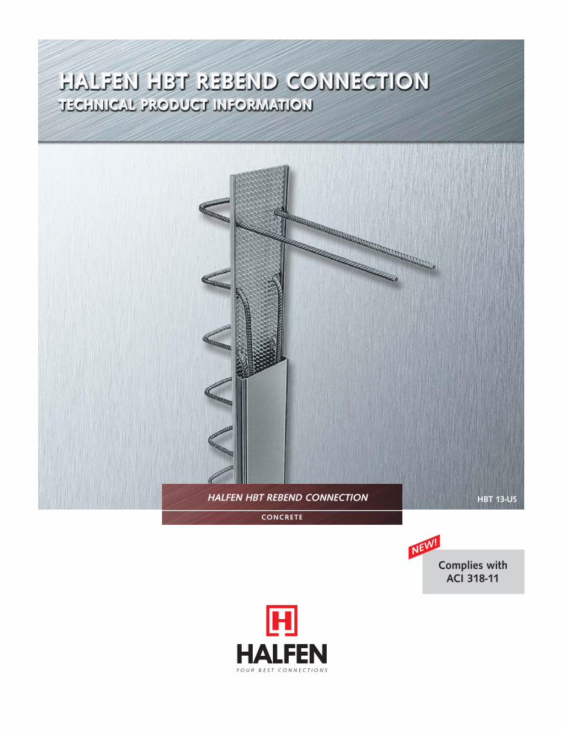
HALFEN HBT Rebend Connection.For reinforcement continuity and structural integrity for
segmental pours in reinforced concrete structures.
The HBT Rebend Connections are cast into the face of a concrete member. After curing of the fi rst pour, the bars are then straightened, ready for lapping with the reinforcing steel of the subsequent pour.
HALFEN USA Inc. • PO Box 547 Converse • TX 78109Phone: + 1 800.423.9140 • www.halfenusa.com • [email protected]
▪ Requires complicated and time consuming formwork
▪ Projecting bars in confi ned spaces are a hazard
▪ Restricts access▪ Roughening of narrow areas around
and between the reinforcement
▪ Accelerates pour schedules▪ Reduces field labor cost▪ No roughening of narrow areas around
and between the reinforcement▪ Simplifies formwork design▪ Improves safety and working access▪ Prevents damage/waste of formwork▪ No post-drilling in concrete areas with
high density of reinforcement
Traditional Concrete Joint
HALFEN HBT Rebend Connection

HALFEN HBT REBEND CONNECTION
© 2014 HALFEN · HBT 13-US · www.halfenusa.com
Contents
System description 4-5
Rebending of reinforcing steel 6
Product range 7
Application examples 8-9
Standard element single row: HBT 85 and 125 10
Standard element double row: HBT 120, 150, 190 and 220 11
HBT Rebend Connection adapted to curved formwork 12
Engineering Request Form 13
Installation Instructions 14
HBT Rebend Connection project report 15
3
© t
omja
sny.
com
HALFEN HBT REBEND CONNECTION
© 2014 HALFEN · HBT 13-US · www.halfenusa.com
System descr ipt ion
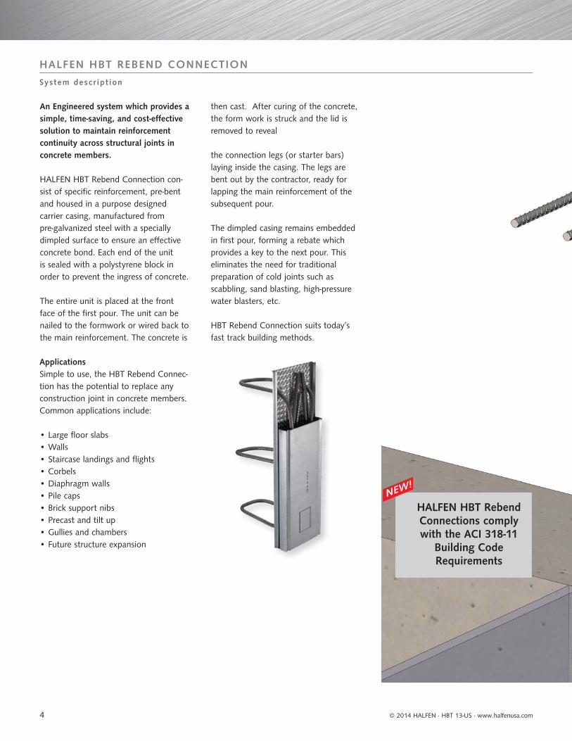
An Engineered system which provides a simple, time-saving, and cost-eff ective solution to maintain reinforcement continuity across structural joints in concrete members.
HALFEN HBT Rebend Connection con-sist of specifi c reinforcement, pre-bent and housed in a purpose designed carrier casing, manufactured from pre-galvanized steel with a specially dimpled surface to ensure an eff ective concrete bond. Each end of the unit is sealed with a polystyrene block in order to prevent the ingress of concrete.
The entire unit is placed at the front face of the fi rst pour. The unit can be nailed to the formwork or wired back to the main reinforcement. The concrete is
then cast. After curing of the concrete, the form work is struck and the lid is removed to reveal
the connection legs (or starter bars) laying inside the casing. The legs are bent out by the contractor, ready for lapping the main reinforcement of the subsequent pour.
The dimpled casing remains embedded in fi rst pour, forming a rebate which provides a key to the next pour. This eliminates the need for traditional preparation of cold joints such as scabbling, sand blasting, high-pressure water blasters, etc.
HBT Rebend Connection suits today’s fast track building methods.
ApplicationsSimple to use, the HBT Rebend Connec-tion has the potential to replace any construction joint in concrete members. Common applications include:
• Large fl oor slabs• Walls• Staircase landings and fl ights• Corbels• Diaphragm walls• Pile caps• Brick support nibs• Precast and tilt up• Gullies and chambers• Future structure expansion
HALFEN HBT Rebend Connections comply with the ACI 318-11
Building Code Requirements
NEW!
4

HALFEN HBT REBEND CONNECTION
© 2014 HALFEN · HBT 13-US · www.halfenusa.com
Design informat ion
HALFEN has carefully designed the HBT Rebend Connection to optimize its performance while providing a simple installation. When two concretes structures cast at diff erent times are expected to act in a composite manner, the feasible solution is HALFEN.
The advantages of the HALFEN HBT Rebend Connection are as follow:
Provides the required development length in order for the reinforcing steel to achieve the full tensile capacity.
The profi led back provides an optimal bond and shear transfer to the adjacent concrete member. [The Carrier Casing is left in the concrete ensuring that shear load transfer is maintained.]
Ensures a constant roughened surface along the entire length and width of the joint. [In current construction practices, this results quite challenging to achieve in addition of being time consuming.]
Ductile reinforcement steel grade allows the bars to be rebend. Damage of the formwork is prevented without compromising the structural integrity of the connection.
Provides the required development length in order for the reinforcing steel to achieve the full tensile capacity.
The pre-punched cover simplifi es its removal (after curing of the concrete).
The special design of the fl anges of the Carrier Casing provides enough strength to prevent deformation. Hence, ingress of concrete in the case is prevented.
The geometry of the Cover and Carrier Casing forms a keyway which permanently locks the two pours.
5

HALFEN HBT REBEND CONNECTION
© 2014 HALFEN · HBT 13-US · www.halfenusa.com
Rebending of re inforc ing s tee l
Straightening of barsThe most fundamental consideration has been the aspect of rebending yield rein-forcement, which is a prerequisite of the system. Some concern is understanda-ble, as ACI 318-11 section 7.3.1 states that “Reinforcement partially embedded in concrete shall not be fi eld bent, ex-cept as shown on the design drawings or permitted by the licensed design professional”.
As specialists in structural connections, HALFEN has carefully selected the rein-forcing steel for its suitability to be re-bent and defi ning its subsequent perfor-mance afterwards. In addition, HALFEN provides the proper tools to re-bend the bars without compromising the integrity of the connection.
What are the loading diff erences between HBT Rebend Connection and traditional loose/unbent rebar?Structural tests showed that the fl exural and shear strength of construction joints formed with HBT Rebend Connection are no less than those of traditionally formed construction joints.
How should the reinforcing bars be re-bent?Proper bending of reinforcing bars partially embedded in concrete and pro-truding from it can result a challenge. Therefore, proper tools shall be used to re-bend the reinforcing bars and prevent damage of the stress concentrated areas.
The HBT-RZ and HBT-RT Straightening Tools provide a smooth and progressive straightening of the bars. Hence, un-desirable irregular movements are avoided.
Both tools are specially designed to minimize undesirable point contact of the tube on the bar (specially at the stress concentrated area) and most important, to provide continuous support to the outside of the bend during the straightening of the reinforcing steel.
Please download the installation instructions from our website www.halfenusa.com for further explanation.
For confi ned areas, the HBT-RZ tool is recommended
HALFEN HBT fulfi lls the following requirements of the Building Code Requirements for Structural Concrete ACI 318-11:
• Development length of reinforcing steel
• Development length of hooks• Minimum bend diameters• Concrete protection for reinforcement• Shear friction
For typical conditions, the HBT-RT tool is recommended
Front End
6
HALFEN HBT REBEND CONNECTION
© 2014 HALFEN · HBT 13-US · www.halfenusa.com
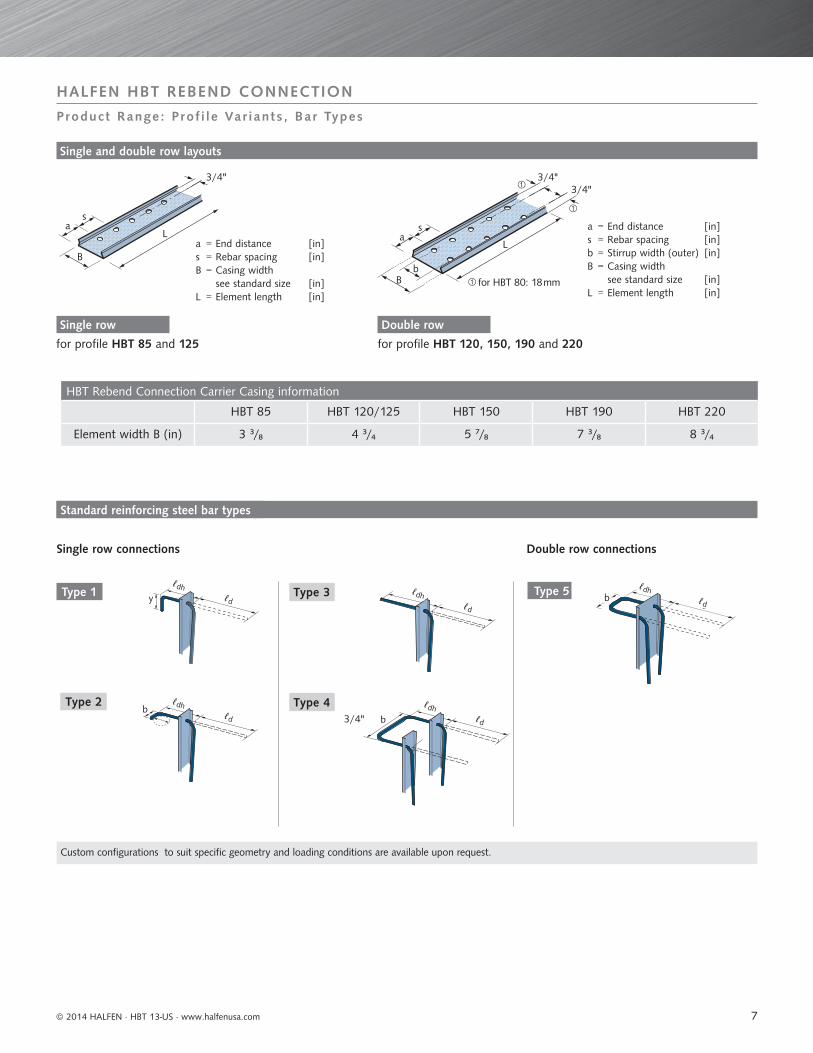
Product Range: Prof i le Var iants , Bar Types
for profi le HBT 85 and 125 for profi le HBT 120, 150, 190 and 220
a = End distance [in]s = Rebar spacing [in]b = Stirrup width (outer) [in]B = Casing width see standard size [in]L = Element length [in]
Single row Double row
a = End distance [in]s = Rebar spacing [in]B = Casing width see standard size [in]L = Element length [in]
Single and double row layouts
for HBT 80: 18 mm
3/4"
sa
B
L
sa
bB
3/4"
L
3/4"
yh
lü bh
lü
Bügeltypen
3/4"
Type 5
Type 2
Type 3
Type 4
Standard reinforcing steel bar types
Type 1
Custom confi gurations to suit specifi c geometry and loading conditions are available upon request.
HBT Rebend Connection Carrier Casing information
HBT 85 HBT 120/125 HBT 150 HBT 190 HBT 220
Element width B (in) 3 ₃/₈ 4 ₃/₄ 5 ₇/₈ 7 ₃/₈ 8 ₃/₄
Single row connections Double row connections
ℓdh ℓdh
ℓdhℓdh
ℓdhℓdh
ℓd ℓd
ℓdℓd
ℓdℓd
7

© 2014 HALFEN · HBT 13-US · www.halfenusa.com
HALFEN HBT REBEND CONNECTION
Appl icat ion examples
Corbel connection to concrete wall
Connection of thick slabs or stair-landings to concrete walls,
Stairs flight and landing slab connection to a
concrete wall
Connection of a thick concrete wall with 2 HBT Elements,
Wall connection to concrete ceiling
Vertical section Vertical section
Horizontal section
Horizontal section
Horizontal section
Horizontal sectionVertical section
Vertical section
Horizontal or vertical section
Vertical section
Wall connection to floor slab
Wall connectionBridge parapet connection to structure
Wall connections to concrete column
Wall corner detail with single or double connection
Connection of precast parapet to balcony
8

HALFEN HBT REBEND CONNECTION
© 2014 HALFEN · HBT 13-US · www.halfenusa.com
Appl icat ion examples
The HALFEN HBT Rebend Connection allows easy and effi cient connection of concrete components at diff erent phases of construction. Perfect connections for numerous applications with multiple combinations of rebar types and profi le widths. HALFEN HBT Rebend Connection are available in #4 reinforcing steel bar size.
Multifunctional Arena Stadium, Duesseldorf, Germany. The HBT Rebend Connections connect columns, walls, and stairs.
Columns Slabs
Deutsche Post Tower, Bonn, Germany. The HBT Rebend Connections connect stairs and walls.
9

HALFEN HBT REBEND CONNECTION
© 2014 HALFEN · HBT 13-US · www.halfenusa.com
Standard e lement s ing le row
Standard reinforcing steel bar types
NOTE: custom HBT confi gurations are available upon request.
y
Y
a
as
L
H1
ℓdℓdh
H2 Pour 2
Pour 1
D1
B
d b
D2
HBT 85 and HBT 125
Type 1
Description example: HBT 85 - #4/8 - 1 - 48Element length L [in]
Bar type
Bar number/bar spacing s [in]
Profi le size
HBT Type 1 — System configuration
Element Length L Bar spacing s [in]
No. of bars End distance a [in]
Standard element L = 48 in
4 12 2
6 8 3
8 6 4
10 5 4
HBT Type 1 - Standard element details
Designation Part no. dimension of starter bars for element thickness case dimensions
ProfileBar size/
spacing [in] 054.220ℓd
[in]*ℓdh [in]
y [in] **D1 [in] D2 [in] Width B [in]
Height H1 [in]
Height with cover H2 [in]
HBT 85
#4/6 - 00001 19 9 1/2 8 ≥ 11 ≥ 3 1/2 3 3/8 1/2 1 1/8
#4/8 - 00002 19 9 1/2 8 ≥ 11 ≥ 3 1/2 3 3/8 1/2 1 1/8
#4/10 - 00003 19 9 1/2 8 ≥ 11 ≥ 3 1/2 3 3/8 1/2 1 1/8
Profile 054.240
HBT 125
#4/4 - 00001 19 9 1/2 8 ≥ 11 ≥ 5 4 3/4 1/2 1 1/8
#4/6 - 00002 19 9 1/2 8 ≥ 11 ≥ 5 4 3/4 1/2 1 1/8
#4/8 - 00003 19 9 1/2 8 ≥ 11 ≥ 5 4 3/4 1/2 1 1/8
#4/10 - 00004 19 9 1/2 8 ≥ 11 ≥ 5 4 3/4 1/2 1 1/8
* Standard dimension; length can be reduced to suit project’s dimensions. However, it shall not be less than the larger of 8db and 6in.** Standard dimension; hooks can be provided to suit design dimensions.Reinforcing bar dimensions are out to out of bars.
Type 3 Type 4Type 2
System:
ℓdhℓdh
ℓdh
ℓdℓd
ℓd
ℓdh
ℓd
10
HALFEN HBT REBEND CONNECTION
© 2014 HALFEN · HBT 13-US · www.halfenusa.com
NOTE: custom HBT confi gurations are available upon request.
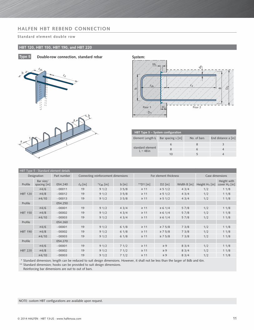
Standard e lement double row
b
as
ab
L
H1
b
ℓdh
D1
H2
ℓd
B D2
System:
HBT 120, HBT 150, HBT 190, and HBT 220
Type 5 Double-row connection, standard rebar
Pour 1 Pour 2
HBT Type 5 – System configuration
Element Length L Bar spacing s [in] No. of bars End distance a [in]
standard element L = 48 in
6 8 3
8 6 4
10 5 4
HBT Type 5 - Standard element details
Designation Part number Connecting reinforcement dimensions For element thickness Case dimensions
ProfileBar size/
spacing [in] 054.240 ℓd [in] *ℓdh [in] b [in] **D1 [in] D2 [in] Width B [in] Height H1 [in]Height with cover H2 [in]
HBT 120
#4/6 - 00011 19 9 1/2 3 5/8 ≥ 11 ≥ 5 1/2 4 3/4 1/2 1 1/8
#4/8 - 00012 19 9 1/2 3 5/8 ≥ 11 ≥ 5 1/2 4 3/4 1/2 1 1/8
#4/10 - 00013 19 9 1/2 3 5/8 ≥ 11 ≥ 5 1/2 4 3/4 1/2 1 1/8
Profile 054.250
HBT 150
#4/6 - 00001 19 9 1/2 4 3/4 ≥ 11 ≥ 6 1/4 5 7/8 1/2 1 1/8
#4/8 - 00002 19 9 1/2 4 3/4 ≥ 11 ≥ 6 1/4 5 7/8 1/2 1 1/8
#4/10 - 00003 19 9 1/2 4 3/4 ≥ 11 ≥ 6 1/4 5 7/8 1/2 1 1/8
Profile 054.260
HBT 190
#4/6 - 00001 19 9 1/2 6 1/8 ≥ 11 ≥ 7 5/8 7 3/8 1/2 1 1/8
#4/8 - 00002 19 9 1/2 6 1/8 ≥ 11 ≥ 7 5/8 7 3/8 1/2 1 1/8
#4/10 - 00003 19 9 1/2 6 1/8 ≥ 11 ≥ 7 5/8 7 3/8 1/2 1 1/8
Profile 054.270
HBT 220
#4/6 - 00001 19 9 1/2 7 1/2 ≥ 11 ≥ 9 8 3/4 1/2 1 1/8
#4/8 - 00002 19 9 1/2 7 1/2 ≥ 11 ≥ 9 8 3/4 1/2 1 1/8
#4/10 - 00003 19 9 1/2 7 1/2 ≥ 11 ≥ 9 8 3/4 1/2 1 1/8
* Standard dimension; length can be reduced to suit design dimensions. However, it shall not be less than the larger of 8db and 6in.** Standard dimension; hooks can be provided to suit design dimensions.
Reinforcing bar dimensions are out to out of bars.
ℓdh
ℓd
d b
11

HALFEN HBT REBEND CONNECTION
© 2014 HALFEN · HBT 13-US · www.halfenusa.com
HBT technica l spec i f i cat ions
• Reinforcing Steel Grade: 60; meets ASTM A615/A615M and ASTM A706/A706M
• Reinforcing steel size: #4 bar
• Bending roll diameter at the rebending angle dBR=6 x db.
• Seven diff erent profi les to suit diff erent concrete structures’ geometry
• Casing available for single or double bars, 13 diff erent bar shapes in the range
• Standard element lengths: 48”
• Custom solutions available * Minimum concrete cover “c” must be attained for all steel sections at the construction joint.
Carrier Casing
Starter Rebar ( #4)
HBT Rebend Connection adapted to curved formwork
Caution when working with an angle-grinder! The reinforcing steel bars in the HBT-Casing must not be damaged.
Making incisions in the HBT-CasingUsing an angle-grinder, cut approximately 3/8 in. deep incisions symmetrically into both
sides of the casing at regular intervals. As a result the HBT Housing loses its rigidity, ea-
sing fi xing to the formwork. To achieve a better fi t to smaller curvature (< 10 ft.), up to
seven incisions per side are possible. After fi xing the HBT Housing to the formwork cover
the incisions with adhesive tape to prevent concrete seeping into the casing.
HBT-Element fi tted to a convex curvatureRV radius ≥ ca. 10 ft.; smaller radius is achieved with more incisions.
HBT-Element fi tted to a concave curvatureRC radius ≥ ca. 10 ft.; smaller radius is achieved with more incisions.
3/8"
3/8"
3/8" 3/8"
3/8"
3/8"
* c
12

HALFEN HBT REBEND CONNECTION
© 2014 HALFEN · HBT 13-US · www.halfenusa.com
Engineer ing request form
Project information
In order for us to be able to select the most effi cient system for your project, please:1. Provide the required information, questions 1 to 5 in the section ’Project Information’.2. Provide the information about the project. 3. Fax to 877-683-4910, e-mail to [email protected] or e-mail to sales representative.
1. Project Name:2. Project Address:3. Location, City: State:4. Company:5. Contact Person:6. Please provide the following HBT information:
Connection ℓd HBT profi le
Bar # Bar type Bar spacing s [in]
ldh [in] ld [in] b [in] y [in] Element lengthL [in]
Quantity [ea]
Connection ℓd * Maximum factored shear, Vu (kip/ft)
* Maximum factored moment, Mu (kip/ft)
Connection description
7. Please provide the following project information:
8. Concrete Strength, f'c: [ksi] 9. Steel Yield Stress, fy: [ksi]
* LRFD factored loads
13
HALFEN HBT REBEND CONNECTION
© 2014 HALFEN · HBT 13-US · www.halfenusa.com
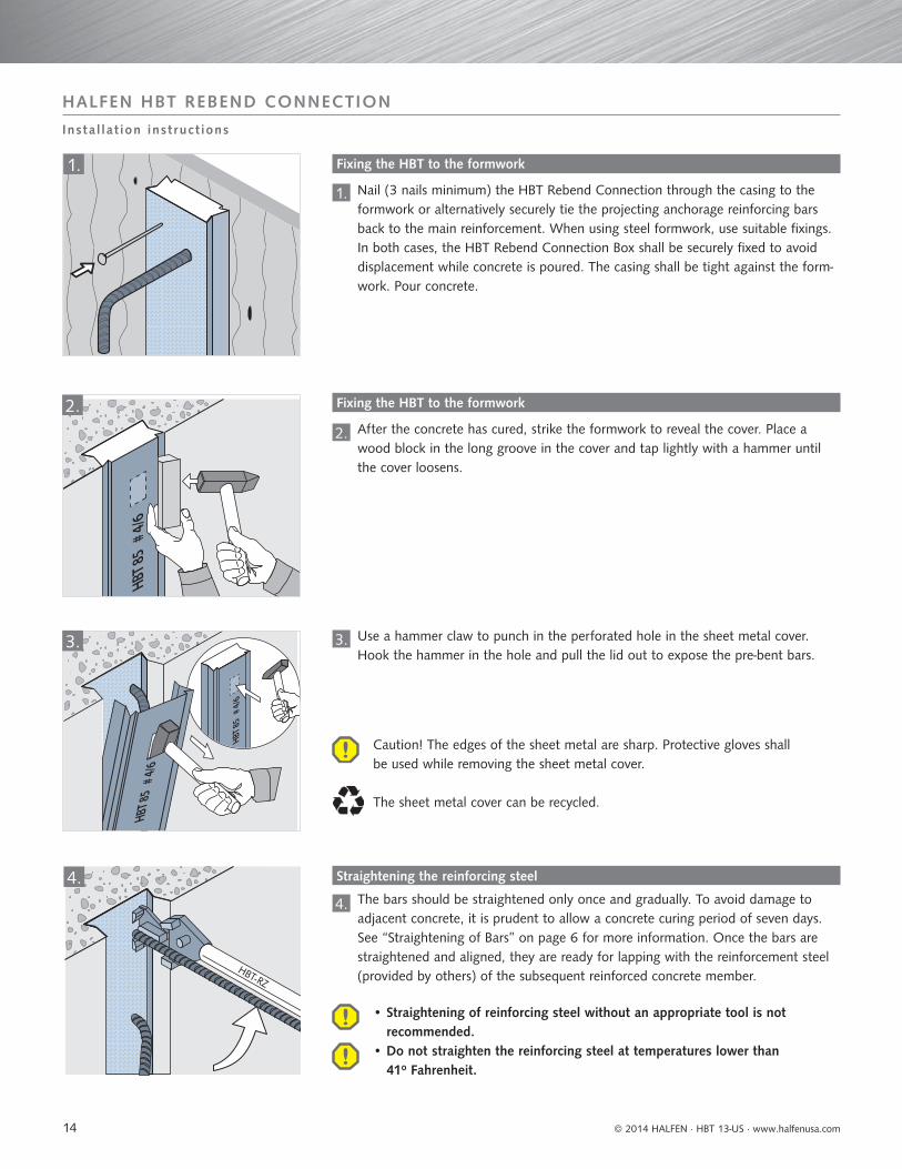
Insta l la t ion inst ruct ions
1.
HBT 8
5# 4
/6
2.
HBT 8
5# 4
/6
HBT 8
5# 4
/6
3.
4.
Fixing the HBT to the formwork
1. Nail (3 nails minimum) the HBT Rebend Connection through the casing to the formwork or alternatively securely tie the projecting anchorage reinforcing bars back to the main reinforcement. When using steel formwork, use suitable fi xings. In both cases, the HBT Rebend Connection Box shall be securely fi xed to avoid displacement while concrete is poured. The casing shall be tight against the form-work. Pour concrete.
Fixing the HBT to the formwork
Straightening the reinforcing steel
2.
3.
4.
After the concrete has cured, strike the formwork to reveal the cover. Place a wood block in the long groove in the cover and tap lightly with a hammer until the cover loosens.
Use a hammer claw to punch in the perforated hole in the sheet metal cover. Hook the hammer in the hole and pull the lid out to expose the pre-bent bars.
The bars should be straightened only once and gradually. To avoid damage to adjacent concrete, it is prudent to allow a concrete curing period of seven days. See “Straightening of Bars” on page 6 for more information. Once the bars are straightened and aligned, they are ready for lapping with the reinforcement steel (provided by others) of the subsequent reinforced concrete member.
Caution! The edges of the sheet metal are sharp. Protective gloves shall be used while removing the sheet metal cover.
The sheet metal cover can be recycled.
• Straightening of reinforcing steel without an appropriate tool is not recommended.
• Do not straighten the reinforcing steel at temperatures lower than 41o Fahrenheit.
14

© 2014 HALFEN · HBT 13-US · www.halfenusa.com
HALFEN HBT REBEND CONNECTION
HBT Rebend Connection installed in the New Westminster Civic Centre – wall to slab application
As the construction industry keeps evolv-ing, so do construction practices; time is money.
HALFEN specializes in designing and manufacturing structural connections products. We look for ways to help the engineers and contractors improving traditional construction methods, while keeping an eye on the bottom line.
Over 470 HALFEN HBT Rebend Connec-tions were supplied to the City of New Westminster Civic Centre in Vancouver, Canada. A total of 1542 linear foot of HBT Rebend connections were used for the wall to slab connection. In addition to reducing fi eld labor cost providing a constant rough surface area along the keyway, the HBT accelerated the pour schedules.
New Westminster Civic Centre, Canada
Close up of the HBT Rebend ConnectionsHBT Rebend Connections installed along the width of the walls.
15
R -
020
- US
- 04/
14
XXXX 05
/14
© 2
014
HA
LFEN
Gm
bH, G
erm
any
appl
ies
also
to
copy
ing
in e
xtra
cts.
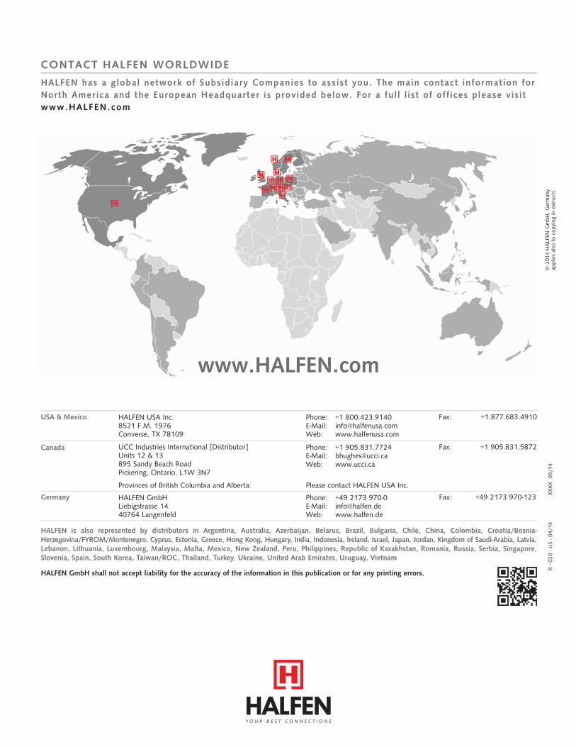
CONTACT HALFEN WORLDWIDE
www.HALFEN.com
HALFEN has a global network of Subsidiary Companies to assist you. The main contact information for North America and the European Headquarter is provided below. For a ful l l ist of off ices please visit www.HALFEN.com
HALFEN GmbH shall not accept liability for the accuracy of the information in this publication or for any printing errors.
HALFEN is also represented by distributors in Argentina, Australia, Azerbaijan, Belarus, Brazil, Bulgaria, Chile, China, Colombia, Croatia/Bosnia-Herzegovina/FYROM/Montenegro, Cyprus, Estonia, Greece, Hong Kong, Hungary, India, Indonesia, Ireland, Israel, Japan, Jordan, Kingdom of Saudi-Arabia, Latvia, Lebanon, Lithuania, Luxembourg, Malaysia, Malta, Mexico, New Zealand, Peru, Philippines, Republic of Kazakhstan, Romania, Russia, Serbia, Singapore, Slovenia, Spain, South Korea, Taiwan/ROC, Thailand, Turkey, Ukraine, United Arab Emirates, Uruguay, Vietnam
USA & Mexico HALFEN USA Inc.8521 F.M. 1976Converse, TX 78109
Phone: +1 800.423.9140E-Mail: [email protected]: www.halfenusa.com
Fax: +1.877.683.4910
Canada UCC Industries International [Distributor]Units 12 & 13895 Sandy Beach RoadPickering, Ontario, L1W 3N7
Provinces of British Columbia and Alberta: Please contact HALFEN USA Inc.
Phone: +1 905.831.7724E-Mail: [email protected]: www.ucci.ca
Fax: +1 905.831.5872
Fax: +49 2173 970-123Germany HALFEN GmbHLiebigstrasse 14 40764 Langenfeld
Phone: +49 2173 970-0 E-Mail: [email protected]: www.halfen.de