Embed Size (px)
Citation preview
HyQuest Solutions Pty Ltd
Hartbeat and Hartbeat plus instruction manual Issue 2:18/1/2016
© Copyright
1
QUALITY SYSTEM
ISO: 9001
CERTIFIED
INSTRUCTION MANUAL
HS–HartbeatandHS‐HartbeatPlus
Model HBT1 and HBT1PLUS
HYQUEST SOLUTIONS PTY LTD 48-50 Scrivener St, Warwick Farm, NSW 2170, AUSTRALIA
Phone: +61 2 9601 2022 Fax: +61 2 9602 6971 Email: [email protected] Web: www.hyquestsolutions.com.au

HyQuest Solutions Pty Ltd
Hartbeat and Hartbeat plus instruction manual Issue 2:18/1/2016
© Copyright
2
TABLE OF CONTENTS
1. INTRODUCTION .............................................................. 3
1.1 HS-Hartbeat - Overview .................................................................. 4 1.2 HS-Hartbeat Plus - Overview ............................................................ 4
2. INSTALLATION ............................................................... 5
2.1 HS-Hartbeat (HBT1) ...................................................................... 6 2.2 HS-Hartbeat Plus (HBT1 Plus) .......................................................... 7 2.3 Configuring the Hart Sensor ............................................................. 8
3. OPERATION ................................................................. 10
3.1 How it works .............................................................................. 10 3.2 LED Indicators (HBT1 and HBT1 Plus) ............................................... 12 3.3 DIP Switch Options ...................................................................... 12 3.4 LCD Menu Structure (HBT1 Plus) ..................................................... 14
4. SDI-12 COMPLIANT COMMANDS ......................................... 15
4.1 Measure and Data Command Format ................................................ 16 4.2 Hartbeat Status .......................................................................... 17 4.3 RS232 Implementation of SDI-12 ..................................................... 18 4.4 SDI-12 Special X Commands ........................................................... 19
5. MODBUS COMMANDS AND OVERVIEW (HBT1) ......................... 23
5.1 Read Discrete Output Coil (F/C 01) .................................................. 24 5.2 Write Single Discrete Output Coil (F/C 05) ......................................... 25 5.3 Write Multiple Discrete Output Coil (F/C 15) ...................................... 26 5.4 Read Discrete Input Contact (F/C 02) ............................................... 27 5.5 Read Analog Input Register (F/C 04) ................................................. 28 5.6 Read Analog Output Holding Register (F/C 03) .................................... 30 5.7 Write a Single Analog Output Register (F/C 06) ................................... 32 5.8 Write Multiple Analog Output Holding Registers (F/C 16) ....................... 33 5.9 Read Device ID (F/C 43) ................................................................ 34
6. SPECIFICATIONS ............................................................ 35
6.1 Hartbeat (HBT1) ......................................................................... 35 6.2 Hartbeat Plus (HBT1 Plus) ............................................................. 36
APPENDIX A HART PROTOCOL DESCRIPTION .............................. 37
A.1 Dynamic Variables .................................................................... 37 A.2 Hart Commands ........................................................................ 38 A.3 Hart Standard Unit Codes ............................................................ 39

HyQuest Solutions Pty Ltd
Hartbeat and Hartbeat plus instruction manual Issue 2:18/1/2016
© Copyright
3
1. INTRODUCTION
What is Hart ? “Hart” is an acronym for Highway Addressable Remote Transducer and was developed in the late 1980’s. The HART Protocol makes use of FSK (Frequency Shift Keying) to superimpose digital communication signals at a very low level on top of a 4-20mA signal. This allows two-way communications to take place between a smart sensor and a Data Logger / RTU. The HART Protocol communicates at 1200 baud without interrupting the 4-20mA signal. As the digital FSK signal is phase continuous, there is no interference with the 4-20mA signal. Why use Hart instead of just 4-20mA ? There are 2 main reasons: 1. Hart makes it possible for additional information, beyond just the normal process variable, to be communicated to/from a smart sensor. (Such as configuration, diagnostics, and additional measurement values.) 2. The accuracy of a sensor taking digital measurements can be lost when you consider the measurement is converted to an analog 4-20mA signal via a D-A converter in the sensor, and then converted back to a digital value via an A-D converter in the Data Logger. Each of these converters require their own voltage reference which are always affected by temperature, and the quantisation to/from an analog signal (8 bit, 12 bit, 16bit) also introduces errors. (Sensor manufacturers can be quite clever in hiding these effects in their specifications.) So communications via Hart will give you the best possible accuracy from a sensor.

HyQuest Solutions Pty Ltd
Hartbeat and Hartbeat plus instruction manual Issue 2:18/1/2016
© Copyright
4
1.1 HS-Hartbeat - Overview The Hydrological Services “HS-Hartbeat” allows any 4-20mA “Hart” device to be connected to an SDI-12 Data Logger and/or an RS485 Modbus RTU. LED’s on the interface give an indication of the supply voltage, the 4-20mA / Hart operation, SDI-12 data transfers or RS485 Modbus data transfers. Internally, the interface has a boost-buck converter that ensures the 4-20mA/Hart device is operating from a constant 16V supply with a 250 ohm burden resistor, independent of the supply voltage which is 10V to 30V DC. The dual SDI-12 interface can be particularly useful when the retrieved data needs to be shared between different government authorities - and the optional 2 wire RS485 Modbus connection may be useful for industrial applications. (An internal DIP switch allows the second port SDI-12 / RS485 Modbus selection.) The 4 x data values returned from the Hart Command 33 “Read Device Variables” are passed through to the SDI-12 and Modbus Interface – and combined with other information such as Battery Voltage and link Status. An external Hart Master (such as the “Vega Connect”) may be connected to the Hart device while it is connected to the Hartbeat, to perform complex configuration and or calibration. (An internal DIP switch enables the option to power the 4-20mA loop but not perform any Hart commands.) The extended voltage range allows this interface to be used in 12V solar powered systems through to 24V powered RTU’s. The loop power on the Hart interface may be configured to be present all of the time, or switched off if power consumption is a critical issue. 1.2 HS-Hartbeat Plus - Overview
4-20mA/Hart
10 to 30V DC
SDI-12 #1 Data Logger #1
SDI-12 #2
RS485 Modbus
Data Logger #2 or RTU
… OR …
AND
Hart to SDI-
12/Modbus
Vega water level radar with Hart interface.

HyQuest Solutions Pty Ltd
Hartbeat and Hartbeat plus instruction manual Issue 2:18/1/2016
© Copyright
5
The Hydrological Services “HS-Hartbeat Plus” allows any 4-20mA “Hart” device to be connected to an SDI-12 Data Logger and/or a 4-20mA data logger. The LCD indicates the water level, the supply voltage, the system status, and allows the configuration of the 4-20mA range and some configuration of the Hart device. Internally, the interface has a boost-buck converter that ensures the 4-20mA/Hart device is operating from a constant 16V supply with a 250 ohm burden resistor, independent of the supply voltage which is 10V to 18V DC. The dual SDI-12 interface can be particularly useful when the retrieved data needs to be shared between different government authorities - and the 4-20mA interface may be useful to interface to older model Data Loggers. (All 3 interfaces can be used at the same time.) The 4 x data values returned from the Hart Command 33 “Read Device Variables” are passed through to the SDI-12 – and combined with other information such as Battery Voltage and link Status. An external Hart Master (such as the “Vega Connect”) may be connected to the Hart device while it is connected to the Hartbeat, to perform complex configuration and or calibration. (An internal DIP switch enables the option to power the 4-20mA loop but not perform any Hart commands.) The voltage range allows this interface to be used in 12V solar powered systems.
2. Installation
4-20mA/Hart
10 to 18V DC
SDI-12 #1
Data Logger #3
SDI-12 #2
Data Logger #1
AND
AND
Hart to SDI-12/4-20mA/LCD
Interface
Vega water level radar with Hart interface.
4-20mA
Data Logger #2

HyQuest Solutions Pty Ltd
Hartbeat and Hartbeat plus instruction manual Issue 2:18/1/2016
© Copyright
6
2.1 HS-Hartbeat (HBT1) The default SDI-12 address on SDI-12 #1 interface is 0. The default SDI-12 address on SDI-12 #2 interface is 1. The default Modbus address is 1 and the default baud rate is 19200/8/N/1 The above defaults may need to be changed before integrating into a system. Connections are made via a 12 way plug in screw terminal block. Go to Section 2.3 to configure the Hart Sensor itself.
Hart Sensor
SDI-12 Logger
#1
SDI-12 Logger
#2
RS485 Modbus Logger
Earth Hart 4-20+
Hart 4-20-
10V to 30V
Com (0V)
Com (0V)
Com (0V)
SDI #1
SDI #2
Com (0V) 485+ 485-
Spare
Earth
12V Battery
..OR..
Use DIP SW1-1 to select between
SDI-12 or RS485 modbus second
interface
HyQuest Solutions Pty Ltd
Hartbeat and Hartbeat plus instruction manual Issue 2:18/1/2016
© Copyright
7
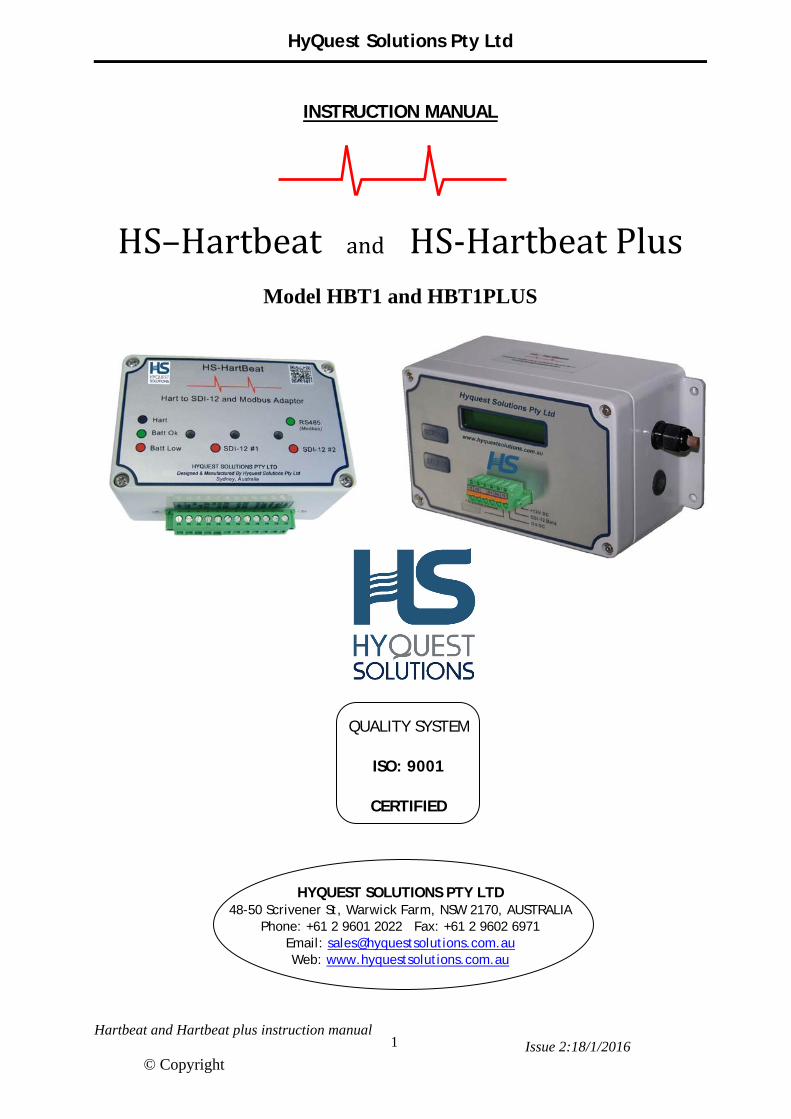
Earth
2.2 HS-Hartbeat Plus (HBT1 Plus) The default SDI-12 address on the Main SDI-12 interface is 0. The default SDI-12 address on the Extra SDI-12 interface is 1. The default 4-20mA output Range is 0-30m (or 0-30ft) depending on the “Display Units” setting (see the LCD menu structure in Section 3.4). (The 4-20mA output is optically isolated from the Hartbeat Plus electronics and must be loop powered !) These defaults may need to be changed before integrating into a system. Connections are made via an internal 3 way screw terminal block and a 6 way plug in spring terminal block. Connect the enclosure case to station Earth via one of the mounting bolts and a star washer to cut through the enclosure powder coating. Go to Section 2.3 to configure the Hart Sensor itself.
Hart Sensor
SDI-12 Logger (Main)
SDI-12 Logger (Extra)
4-20mA Logger providing loop power – this device looks like an isolated 2 wire sensor.
Shield Hart 4-20+
Hart 4-20-
+12V DC
0V DC
Internal 3 way screw terminal block
SDI Data
Extra SDI
-4-20 mA
+4-20 mA
12V Battery

HyQuest Solutions Pty Ltd
Hartbeat and Hartbeat plus instruction manual Issue 2:18/1/2016
© Copyright
8
2.3 Configuring the Hart Sensor When configuring the Hart Sensor, the settings are stored in the Hart device – so the data read by the Hartbeat is the same as that read by any other device connected to the Hart Sensor. The Hart Sensor parameters can be set in various ways :
Using SDI-12 (in the Hartbeat or Hartbeat Plus) (See Section 4.4)
Using Modbus (in the Hartbeat) (See Section 5.7)
Using the LCD (in the Hartbeat Plus) (See section 3.4)
Using a sensor configuration tool (such as a Vega Plicscom or Vega Connect)
There are 4 main steps in configuring the Hart sensor to get correct readings using one of the methods above :
1. Set the Primary Variable Type to be “Water Level”. See Appendix A.1 for more information. (Example : Set PV Type = 4 for the Vega WL61)
2. Set the Secondary Variable Type to be “Distance to the Water”.
See Appendix A.1 for more information. (Example : Set SV Type = 0 for the Vega WL61)
3. Set the actual Water Level according to the visual Gauge Plate .
When the level is set, the Hartbeat calculates the “Hart Lower Range” parameter, which is then sent to the Hart Sensor. (See Appendix A.1 for more information) (It would also be possible to set the “Lower Range” parameter directly if you wish to calculate the value manually.) NOTE : It has been found when using the Vega sensors, that the “Lower Range” parameter cannot exceed the range of the sensor. (eg. 15m or 35m.) This means that the Water Level cannot exceed the measurement range of the sensor.
4. Set a Damping value suitable for the surface water conditions. The Hart damping is an averaging that takes place within the Hart sensor.
NOTE : Only limited sensor configuration can be performed using the Hartbeat or Hartbeat Plus.

HyQuest Solutions Pty Ltd
Hartbeat and Hartbeat plus instruction manual Issue 2:18/1/2016
© Copyright
9
The following diagram shows the Hartbeat internal circuit that drives the Hart sensor. If an external Hart Configuration device, (such as the Vega Connect) is required to configure the Hart Sensor, then it can be connected to the Hartbeat (or Hartbeat Plus) between the 0V and the Hart 4-20- terminals as shown. When the Hartbeat DIP SW1-4 is set to the on position, the Hartbeat stops sending Hart commands, but leaves 16V to power the Hart device. The external Hart Configuration device can now communicate with the Hart Sensor. When finished configuring the Hart device, DO NOT FORGET to put the DIP SW1-4 back to the on position to allow the Hartbeat communications to resume.
12V Battery
16V Boost/Buck Converter
250ohm Hart Sensor (Radar)
Hartbeat
Hart Modem
Hart 4-20+
Hart 4-20-
16V
uC
0V
10V -30V
0V
- +
External Hart Configuration Device
Eg. Vega Connect
*** NOTE *** Set Hartbeat DIP SW1-4 on, to allow
external Hart Configuration.
HyQuest Solutions Pty Ltd
Hartbeat and Hartbeat plus instruction manual Issue 2:18/1/2016
© Copyright
10
3. OPERATION
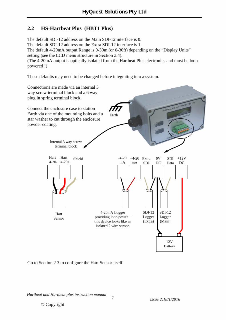
3.1 How it works The operation of the Hartbeat and Hartbeat Plus is completely dependent on the data returned from the Hart enabled sensor – and is merely an interface and protocol converter. It was decided not to manipulate the returned Hart data in any way, but to simply provide a way to implement limited configuration directly from a Data Logger. The Hart protocol provides the ability to have some basic commands, as well as manufacturer specific commands that allow complex configuration - such as viewing the radar echo. (Manufacturer’s usually keep these specific commands close to their chest, so we don’t have access to them.) The Hart protocol is very flexible and allows four Dynamic Variables to be configured. (See Appendix A.1) These must be configured so the Primary Variable (PV) is the “Water Depth” and the Secondary Variable (SV) is the “Distance to the Water” – which can be done through the Hartbeat and Hartbeat Plus, along with a damping parameter and the measured water level. Automatic Measurement When DIP Sw1-3 is in the on position, the 4-20mA Hart loop has 16V constantly applied, so after the Hart sensor has powered-up, measurements will continue to be returned. The following timing diagram shows the first measurement waiting for the Hart sensor to initialize, and subsequent measurements being returned much quicker as the Hart device stays powered up. The blue LED on the Hartbeat gives an indication of the Hart device status – and the LCD on the Hartbeat Plus tells you what’s happening.
12V Supply
16V Hart Power
3 Blue LED (Hart Polling)
3 2 2 2 2 1 1 1 1
SDI-12 Meas
Hart 4-20mA power stays on when polling finished
SDI-12 Service Req => Data Ready
SDI-12 Data Read Long time for Hart power up and initialise Subsequent times
are shorter
Hart Initialise Hart sensor power up Hart Ready
HyQuest Solutions Pty Ltd
Hartbeat and Hartbeat plus instruction manual Issue 2:18/1/2016
© Copyright
11
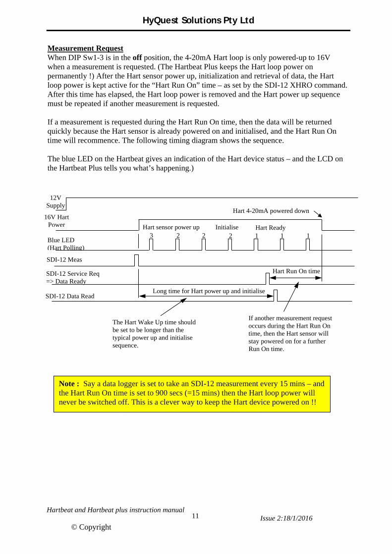
Measurement Request When DIP Sw1-3 is in the off position, the 4-20mA Hart loop is only powered-up to 16V when a measurement is requested. (The Hartbeat Plus keeps the Hart loop power on permanently !) After the Hart sensor power up, initialization and retrieval of data, the Hart loop power is kept active for the “Hart Run On” time – as set by the SDI-12 XHRO command. After this time has elapsed, the Hart loop power is removed and the Hart power up sequence must be repeated if another measurement is requested. If a measurement is requested during the Hart Run On time, then the data will be returned quickly because the Hart sensor is already powered on and initialised, and the Hart Run On time will recommence. The following timing diagram shows the sequence. The blue LED on the Hartbeat gives an indication of the Hart device status – and the LCD on the Hartbeat Plus tells you what’s happening.)
12V Supply
16V Hart Power
Blue LED (Hart Polling)
3 2 2 2 1 1 1
SDI-12 Meas
Hart 4-20mA powered down
SDI-12 Service Req => Data Ready
SDI-12 Data Read Long time for Hart power up and initialise
Initialise Hart sensor power up Hart Ready
Hart Run On time
If another measurement request occurs during the Hart Run On time, then the Hart sensor will stay powered on for a further Run On time.
The Hart Wake Up time should be set to be longer than the typical power up and initialise sequence.
Note : Say a data logger is set to take an SDI-12 measurement every 15 mins – and the Hart Run On time is set to 900 secs (=15 mins) then the Hart loop power will never be switched off. This is a clever way to keep the Hart device powered on !!

HyQuest Solutions Pty Ltd
Hartbeat and Hartbeat plus instruction manual Issue 2:18/1/2016
© Copyright
12
3.2 LED Indicators (HBT1 and HBT1 Plus) The Hartbeat Plus actually contains a Hartbeat board and the same LED indicators are fitted, however they are only visible when the lid with the LCD is removed – so this LED indicator description does apply to both the Hartbeat and Hartbeat Plus models. By examining the LED’s you can get a good “feel” for what is going on.
LED colour (+position)
Operation Description
Green (LHS) 1 Flash Battery voltage OK This is usually followed by a blue flash when communicating with the Hart device.
Red (LHS) 1 Flash Battery voltage too low < 9.6V (HBT1 and HBT1 Plus) or Battery voltage too high > 30V (HBT1) Note : There is 1.0V hysteresis at the low and hi voltage.
Blue (LHS)
1 Flash Hart poll and response OK 2 Flashes Hart poll and response indicates sensor not ready yet.
3 Flashes Hart poll and no response (Some Hart sensors can take quite a while (30 sec) to initialise themselves after loop power is applied - current is measured so sensor is connected)
No Flash Sensor not detected – check loop voltage and loop current. Red (Centre) Flash SDI-12 #1 comms (HBT1 and HBT1 Plus)
Green (RHS) Flash Modbus comms (HBT1) Comms to LCD board (HBT1 Plus)
Red (RHS) Flash SDI-12 #2 comms (HBT1) When loop power is first applied, the sequence will be something like :
Green LED flash (battery OK) Green LED flash (battery OK) Blue LED flash 3 times (polled Hart device, no response)
Above repeated…
Green LED flash (battery OK) Blue LED flash 2 times (polled Hart device, response, but not ready)
Above repeated…
Green LED flash (battery OK) Blue LED flash 1 time (polled Hart device, response OK) (Gets configuration, then the data….) Above repeated…
3.3 DIP Switch Options

HyQuest Solutions Pty Ltd
Hartbeat and Hartbeat plus instruction manual Issue 2:18/1/2016
© Copyright
13
The Hartbeat and Hartbeat Plus has a 4 way DIP switch that allows a few user configurable options.
Switch Off On HBT1 HBT1 Plus SW1-1 RS485 SDI-12 Selectable Off SW1-2 HS Modbus On Off SW1-3 Req Measure Auto Measure Selectable On SW1-4 Normal External Hart Selectable Selectable
Hartbeat (HBT1) The Hartbeat should always have switch SW1-2 in the on position. The other 3 switches can be user selected, depending on the configuration and functions being used. SW1-1 allows the user to select the function of interface #2. When in the off position, the RS485 Modbus is selected – when in the on position, the second SDI-12 port is selected. SW1-3 allows a lower power mode to be used. When in the off position the Hart 4-20mA loop only has power applied when a measurement is requested – and therefore takes the full power up time of the sensor (may be 60 secs) before a measurement is ready. The advantage is when not taking a measurement, the power consumption is less. When the switch SW1-3 is in the on position, the Hart 4-20mA loop has power applied all of the time – so measurements are returned faster, at the expense of drawing 4-2mA loop current all the time. SW1-4 should be in the off position for normal operation. When this switch is in the on position, the 4-20mA Hart device loop power is applied, but Hart polling is stopped by the Hartbeat to allow and external Hart master access to the Hart sensor to configure the device. (See the installation section for more information.) Hartbeat Plus (HBT1 Plus) The Hartbeat Plus should always have switch SW1-1 and SW1-2 in the off position, and the switch SW1-3 in the on position. SW1-4 should be in the off position for normal operation. When this switch is in the on position, the 4-20mA Hart device loop power is applied, but Hart polling is stopped by the Hartbeat Plus to allow and external Hart master access to the Hart sensor to configure the device. (See the installation section for more information.)
HyQuest Solutions Pty Ltd
Hartbeat and Hartbeat plus instruction manual Issue 2:18/1/2016
© Copyright
14
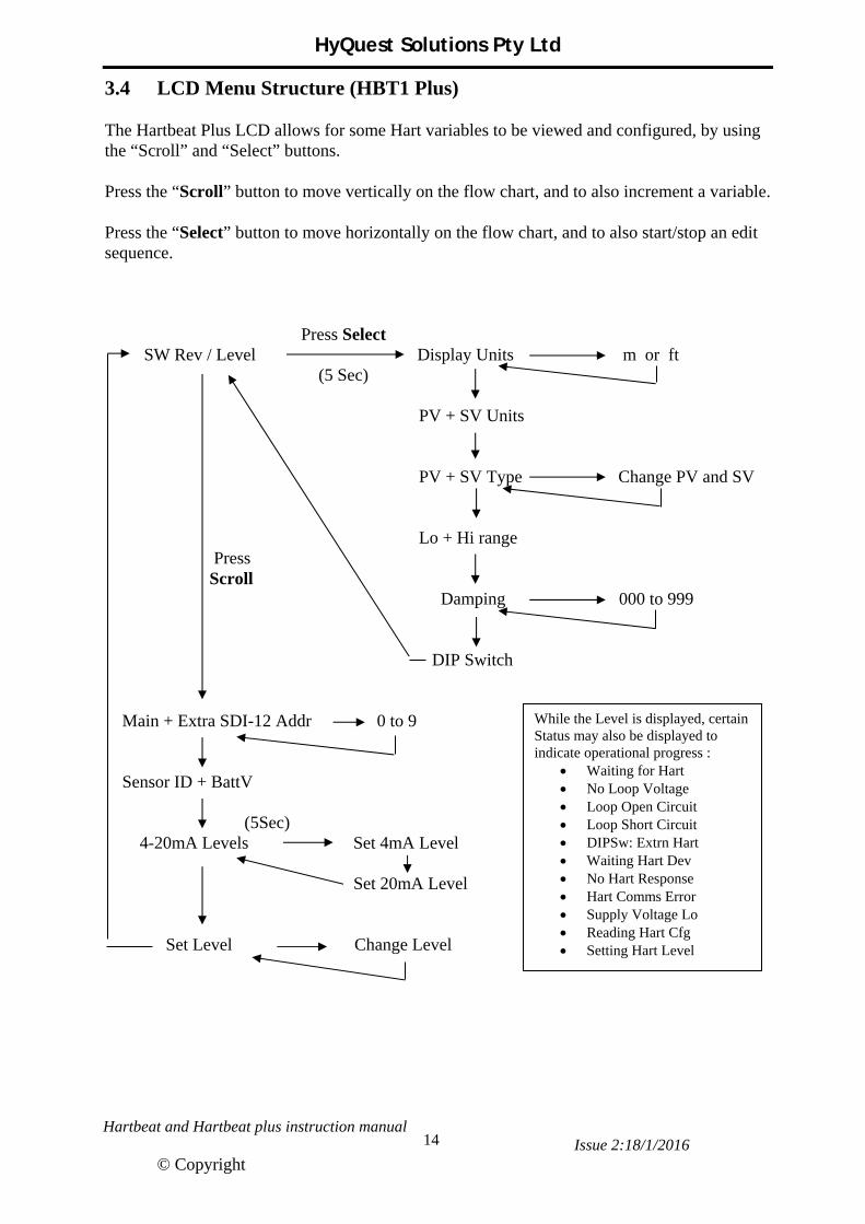
3.4 LCD Menu Structure (HBT1 Plus) The Hartbeat Plus LCD allows for some Hart variables to be viewed and configured, by using the “Scroll” and “Select” buttons. Press the “Scroll” button to move vertically on the flow chart, and to also increment a variable. Press the “Select” button to move horizontally on the flow chart, and to also start/stop an edit sequence. Press Select SW Rev / Level Display Units m or ft (5 Sec) PV + SV Units PV + SV Type Change PV and SV Lo + Hi range Press Scroll Damping 000 to 999 DIP Switch Main + Extra SDI-12 Addr 0 to 9 Sensor ID + BattV (5Sec) 4-20mA Levels Set 4mA Level Set 20mA Level Set Level Change Level
While the Level is displayed, certain Status may also be displayed to indicate operational progress :
Waiting for Hart No Loop Voltage Loop Open Circuit Loop Short Circuit DIPSw: Extrn Hart Waiting Hart Dev No Hart Response Hart Comms Error Supply Voltage Lo Reading Hart Cfg Setting Hart Level
HyQuest Solutions Pty Ltd
Hartbeat and Hartbeat plus instruction manual Issue 2:18/1/2016
© Copyright
15
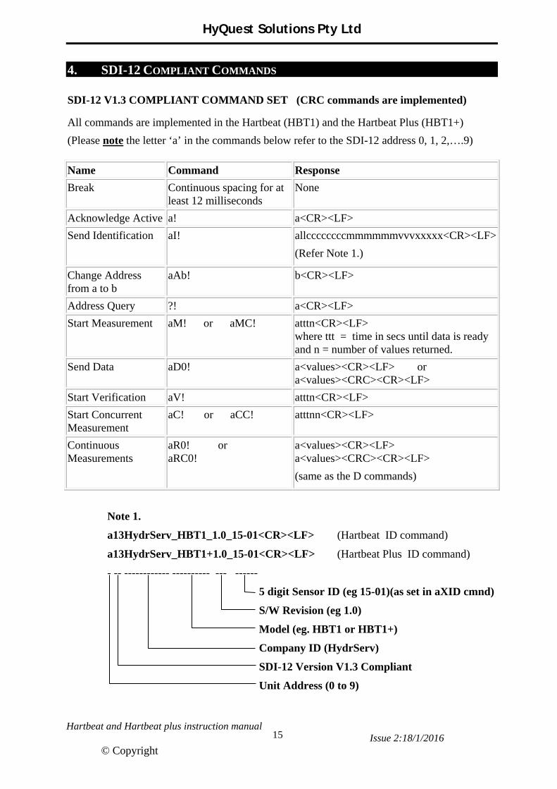
4. SDI-12 COMPLIANT COMMANDS
SDI-12 V1.3 COMPLIANT COMMAND SET (CRC commands are implemented)
All commands are implemented in the Hartbeat (HBT1) and the Hartbeat Plus (HBT1+)
(Please note the letter ‘a’ in the commands below refer to the SDI-12 address 0, 1, 2,….9)
Name Command Response
Break Continuous spacing for at least 12 milliseconds
None
Acknowledge Active a! a<CR><LF>
Send Identification aI! allccccccccmmmmmmvvvxxxxx<CR><LF>
(Refer Note 1.)
Change Address from a to b
aAb! b<CR><LF>
Address Query ?! a<CR><LF>
Start Measurement aM! or aMC! atttn<CR><LF> where ttt = time in secs until data is ready and n = number of values returned.
Send Data aD0! a<values><CR><LF> or a<values><CRC><CR><LF>
Start Verification aV! atttn<CR><LF>
Start Concurrent Measurement
aC! or aCC! atttnn<CR><LF>
Continuous Measurements
aR0! or aRC0!
a<values><CR><LF> a<values><CRC><CR><LF>
(same as the D commands)
Note 1.
a13HydrServ_HBT1_1.0_15-01<CR><LF> (Hartbeat ID command)
a13HydrServ_HBT1+1.0_15-01<CR><LF> (Hartbeat Plus ID command)
- -- ------------ ---------- --- ------
5 digit Sensor ID (eg 15-01)(as set in aXID cmnd)
S/W Revision (eg 1.0)
Model (eg. HBT1 or HBT1+)
Company ID (HydrServ)
SDI-12 Version V1.3 Compliant
Unit Address (0 to 9)

HyQuest Solutions Pty Ltd
Hartbeat and Hartbeat plus instruction manual Issue 2:18/1/2016
© Copyright
16
4.1 Measure and Data Command Format The Hartbeat and Hartbeat Plus can be connected to any type of Hart sensor – and each sensor may take a different amount of time to power up, initialize and obtain a stable reading. The SDI-12 Measure command is expected to return a “Service Request” when a measurement is ready – for this reason an X Command XHWU (Hart Warm Up) allows this time to be configured. It is preset to 60 secs as default, as this appears to be the time it takes a Vega Water Level Radar sensor to return valid measurements after being powered up. (The Measure response adds 1 sec to the Warm Up time to allow an extra timing margin.)
The following example is a communication sequence to SDI-12 address 0.
Logger HartBeat Response Comments Request
0M! 00618 <CR><LF> 8 data values will be ready in at least 61 secs
61 secs (or less) has elapsed
0 <CR><LF> Service request indicating data is ready
0D0! 0+10.319+11.181+0+12.8 <CR><LF> D0 request returns data values 1 to 4
0D1! 0+47.995+83.592 <CR><LF> D1 request returns data values 5 and 6
0D2! 0+18.394+18.4 <CR><LF> D2 request returns data values 7 and 8
Data Value Example Description
1 10.319 Hart Primary Variable (Note 1) (*** Must be configured as the water depth)
2 11.181 Hart Secondary Variable (Note 2) (*** Must be configured as distance to the water)
3 0 Hartbeat Status (0 to 15) See the next page for details.
4 12.8 Battery Voltage as measured by the Hartbeat
5 47.995 Hart Tertiary Variable (Not normally used - for information only)
6 83.592 Hart Quaternary Variable (Not normally used – for information only)
7 18.394 Hart specified loop current (Sensor loop current – as returned via Hart)
8 18.4 Measured loop current (Approx sensor loop current – measured by Hartbeat)
Note 1 : The Hart Primary Variable (PV) is passed through to data value 1. This must be configured in the Hart device as the “water depth”. This can be done using the SDI-12 X command XHPV (Hart Primary Variable) – or it can be done from the LCD in the HBT1 Plus. Note 2 : The Hart Secondary Variable (SV) is passed through to data value 2. This must be configured in the Hart device as the “distance to the water”. This can be done using the SDI-12 X command XHSV (Hart Secondary Variable) – or can be done from the LCD in the HBT1 Plus.

HyQuest Solutions Pty Ltd
Hartbeat and Hartbeat plus instruction manual Issue 2:18/1/2016
© Copyright
17
4.2 Hartbeat Status The Hartbeat status is returned as the 3rd data value in an SDI-12 D0 data command (see the previous page). This status is very important in diagnosing any problems, and determining the validity of the measured data.
Status Number
Description
0 All Hart communications and hardware is OK
1 Supply voltage is too low (< 10V) (The Hart loop supply voltage will be turned off)
2 Supply voltage is too high (> 30V in HBT1 only) (The Hart loop supply voltage will be turned off)
3 Hart comms has not been attempted yet (usually after power up) 4 No Loop Voltage
5 Open Circuit – no loop current is measured (Check to see if Hart sensor is plugged in)
6 Short Circuit – loop current is greater than 24mA (Check to see if Hart loop wiring is short circuit, or if Hart sensor is connected backwards)
7 DIP Switch #4 is on which provides 16V loop power and stops Hart communications from the Hartbeat, allowing an external Hart master such as the “Vega Connect” configuration tool to control the Hart bus.
8
The “Device Error” flag in the Hart reply is set – which can occur while the Hart device is powering up and is not fully initialized. This should automatically clear when the device has initialized – if not, there may be a problem with the Hart device.
9 No comms reply from the Hart device – can occur if the 4-20mA sensor is not a Hart device – can also occur immediately after the Hart device has power applied and has not initialized.
10 Hart longitudinal parity error – a parity error has occurred at the end of one of the Hart messages – this should be a fleeting message.
11 Hart character parity error – a parity error has occurred on one byte of a Hart message – this should be a fleeting message.
12 Hart framing error – a framing error has occurred in a Hart message – this should be a fleeting error.
13 Hart overrun error – an overrun error has occurred in a Hart message – this should be a fleeting error.
14 Hartbeat board internal i2c error – the Hart messages are handled by U1 on the Hartbeat board via i2c, and an error was detected – this should be a fleeting error.
15 Retrieving configuration data from the Hart device – this occurs when the Hart device powers up, and when the PV or SV are set, or when the water level is set.
16 Hartbeat board error – this occurs when in a HBT1 Plus only on the Extra SDI-12 port and indicates an error in the communications between the 2 boards in the Hartbeat Plus
HyQuest Solutions Pty Ltd
Hartbeat and Hartbeat plus instruction manual Issue 2:18/1/2016
© Copyright
18
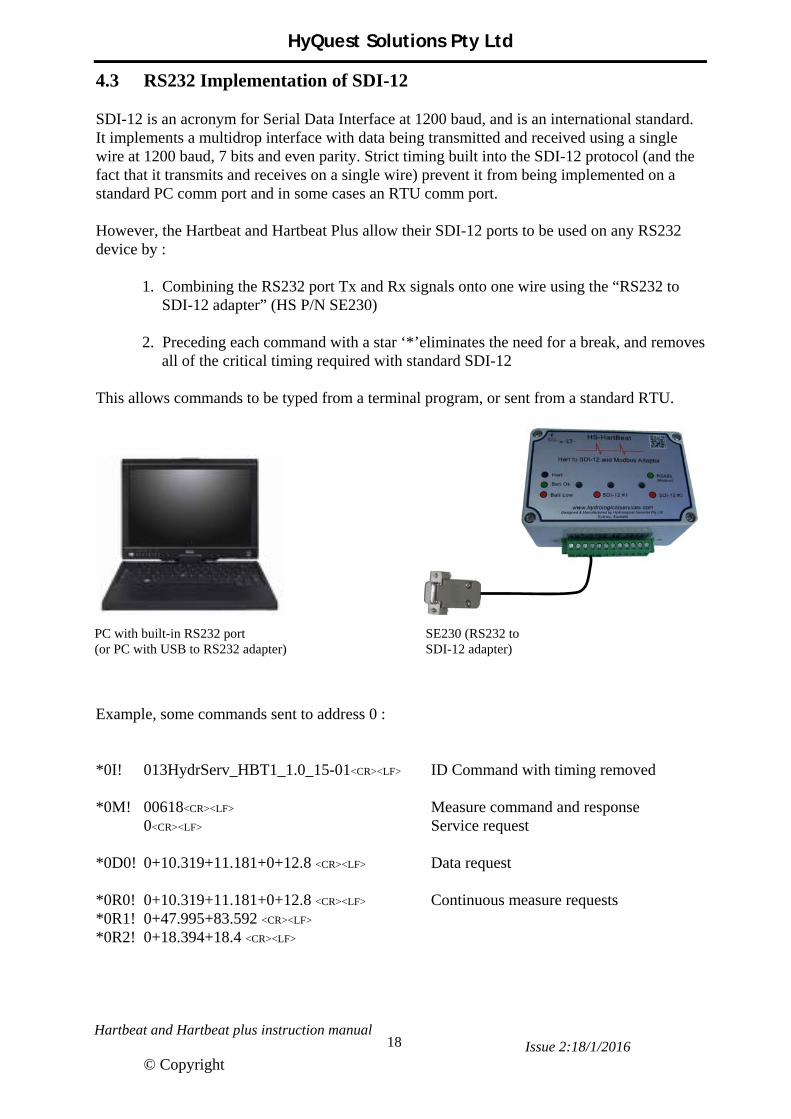
4.3 RS232 Implementation of SDI-12 SDI-12 is an acronym for Serial Data Interface at 1200 baud, and is an international standard. It implements a multidrop interface with data being transmitted and received using a single wire at 1200 baud, 7 bits and even parity. Strict timing built into the SDI-12 protocol (and the fact that it transmits and receives on a single wire) prevent it from being implemented on a standard PC comm port and in some cases an RTU comm port. However, the Hartbeat and Hartbeat Plus allow their SDI-12 ports to be used on any RS232 device by :
1. Combining the RS232 port Tx and Rx signals onto one wire using the “RS232 to SDI-12 adapter” (HS P/N SE230)
2. Preceding each command with a star ‘*’eliminates the need for a break, and removes all of the critical timing required with standard SDI-12
This allows commands to be typed from a terminal program, or sent from a standard RTU. Example, some commands sent to address 0 : *0I! 013HydrServ_HBT1_1.0_15-01<CR><LF> ID Command with timing removed *0M! 00618<CR><LF> Measure command and response 0<CR><LF> Service request *0D0! 0+10.319+11.181+0+12.8 <CR><LF> Data request *0R0! 0+10.319+11.181+0+12.8 <CR><LF> Continuous measure requests *0R1! 0+47.995+83.592 <CR><LF> *0R2! 0+18.394+18.4 <CR><LF>
SE230 (RS232 to SDI-12 adapter)
PC with built-in RS232 port (or PC with USB to RS232 adapter)

HyQuest Solutions Pty Ltd
Hartbeat and Hartbeat plus instruction manual Issue 2:18/1/2016
© Copyright
19
4.4 SDI-12 Special X Commands Note the ‘a’ in the following commands is the SDI-12 address 0 to 9.
Set/Get ID Number
aXID! Get the HartBeat ID. (Response is a+12345<CR><LF>)
aXID+12345! Set the HartBeat ID. Acceptable value any 5 character ascii string. This value appears in the Identify command (aI!). (This is usually set in the Factory to the unit serial number 15-01 = 1st unit made in 2015)
Set/Get Hart Warm Up Time
aXHWU! Get the Warm Up time. (Response is a+060<CR><LF>) This is the time expected for the Hart device to power up and get a valid reading. (Default value is +060 secs) When a Measure command is initiated, this is the time returned in the response. This should be preset by the customer depending on the Hart device connected – usually add a few more secs to allow for device variations.
aXHWU+065! Set the Hart Warm Up time in secs (000 to 999 secs)
Set/Get Hart Run On Time
aXHRO! Get the Hart Run On time. (Response is a+010<CR><LF>) This is the time that the Hart device stays on for after a Measure command is requested. (Default value is +010 secs) If a Hart device takes say 60 secs to warm up before a measurement is ready, it may be prudent to keep the device powered on a little longer in case more Measure commands are requested – this will eliminate the long warm up time for subsequent measurements. NOTE: If the Hart Run On time is longer than the logger SDI-12 sampling time, then the Hart device will stay powered on all of the time.
aXHRO+015! Set the Hart Run On time in secs (000 to 999 secs)
Set/Get Hart Damping aXDMP! Get the Hart Damping (0 to 999 secs) (Response is a+5<CR><LF>)
This is the value returned by the Hart protocol Command 15. – and it the amount of damping applied to the process variable.
aXDMP+12! Set the Hart Damping to 12 secs. This parameter is passed back to the
Hart device via the Hart protocol Command 34.

HyQuest Solutions Pty Ltd
Hartbeat and Hartbeat plus instruction manual Issue 2:18/1/2016
© Copyright
20
Set/Get Hart Primary Variable Type
aXPV! Get the Hart Primary Variable type. (Response is a+0<CR><LF>) The PV is displayed on the Hartbeat Plus as the Water Level and should be set by the customer to the “water level” variable type as defined in the Hart sensor being used. The PV is passed through to the SDI-12 and Modbus data returned.
aXPV+4! Set the Primary Variable type to 4 (See Appendix A.1 for more information on Dynamic Variables)
Get Hart Primary Variable Unit Code
aXPU! Get the Hart Primary Variable unit code. (Response is a+45<CR><LF>) This code is the units of the PV – eg. 45 = metres (A list of Hart unit codes is shown in Appendix A.3)
Set/Get Hart Secondary Variable Type
aXSV! Get the Hart Secondary Variable type. (Response is a+0<CR><LF>) The SV should be set by the customer to reflect the “distance to the water” variable type as defined in the Hart Sensor being used. The SV is passed through to the SDI-12 and Modbus data returned.
aXSV+0! Set the Secondary Variable type to 0 (See Appendix A.1 for more information on Dynamic Variables)
Get Hart Secondary Variable Unit Code
aXSU! Get the Hart Secondary Variable unit code. (Response is a+45<CR><LF>) This code is the units of the SV – eg. 45 = metres (A list of Hart unit codes is shown in Appendix A.3)
Set/Get Hart Tertiary Variable Type
aXTV! Get the Hart Tertiary Variable type. (Response is a+0<CR><LF>) The TV is passed through to the SDI-12 and Modbus data returned.
aXTV+1! Set the Tertiary Variable type to 1 (See Appendix A.1 for more information on Dynamic Variables)
HyQuest Solutions Pty Ltd
Hartbeat and Hartbeat plus instruction manual Issue 2:18/1/2016
© Copyright
21
Get Hart Tertiary Variable Unit Code
aXTU! Get the Hart Tertiary Variable unit code. (Response is a+45<CR><LF>) This code is the units of the TV – eg. 45 = metres (A list of Hart unit codes is shown in Appendix A.3)
Set/Get Hart Quaternary Variable Type
aXQV! Get the Hart Quaternary Variable type. (Response is a+0<CR><LF>) The QV is passed through to the SDI-12 and Modbus data returned.
aXQV+2! Set the Quaternary Variable type to 2 (See Appendix A.1 for more information on Dynamic Variables)
Get Hart Quaternary Variable Unit Code
aXQU! Get the Hart Quaternary Variable unit code. (Response is a+45<CR><LF>) This code is the units of the QV – eg. 45 = metres (A list of Hart unit codes is shown in Appendix A.3)
Set the Gauge Height (Water Level)
aXRGH+15.300! Set the Water Level to 12.400 (m or ft depending on the units) Internally, the Hartbeat takes this number and also the present Secondary Variable (SV) which is the “distance to the water” and calculates the Lower Range. (Lower Range = Water Level + Distance to the Water) The Lower Range is then sent to the Hart sensor using Hart Command 35. (See Appendix A for information on Dynamic Variables and Hart Commands.)
Get/Set the Lower Range
aXRLO! Get the present Hart Lower Range value. (Response is a+15.000<CR><LF>)
aXRLO+15.300! Set the Hart Lower Range value to 15.300 Changing the Lower Range value will affect the Water Level returned from the Hart sensor. (See Appendix A.1 for information on Dynamic Variables)
Get/Set the Upper Range
aXRUP! Get the present Hart Upper Range value. (Response is a+00.000<CR><LF>)
aXRUP+01.000! Set the Hart Upper Range value to 01.000 (See Appendix A.1 for information on Dynamic Variables)
HyQuest Solutions Pty Ltd
Hartbeat and Hartbeat plus instruction manual Issue 2:18/1/2016
© Copyright
22
Get/Set the 4mA Level (*** Only available on Hartbeat Plus Extra SDI-12 port ***)
aX2! Get the 4mA Level. (Response is a+0005.0<CR><LF>)
aX2+0005.0! Set the 4mA Level to 5.0m (or 5.0ft depending on the units used)
Get/Set the 20mA Level (*** Only available on the Hartbeat Plus Extra SDI-12 port ***)
aX3! Get the 20mA Level. (Response is a+0020.0<CR><LF>)
aX3+0020.0! Set the 20mA Level to 20.0m (or 20.0ft depending on the units used)
HyQuest Solutions Pty Ltd
Hartbeat and Hartbeat plus instruction manual Issue 2:18/1/2016
© Copyright
23
5. Modbus Commands and Overview (HBT1) The Modbus protocol is a request/reply protocol, and offers services specified by “function codes”. The basic format of the Modbus protocol is : The device requesting the information is called the Modbus Master and the devices supplying information are Modbus Slaves. In a standard Modbus network, there is one Master and up to 247 Slaves, each with a unique Slave Address from 1 to 247. The Hartbeat Modbus interface operates with 2 wire half duplex, 8 bits, no parity, 1 stop bit and selectable baud rates of 1200, 2400, 4800, 9600, 19200, 38400, 57600, 115200. The default baud rate is 19200, and the default address is 1.
The Function Code tells the slave which type of data to access and whether to read from or write to the data. The list of standard Modbus function codes is :
Function Code Action Implemented Table Name 01 (0x01 hex) Read Yes Discrete Output Coils 05 (0x05 hex) Write single Yes Discrete Output Coil 15 (0x0F hex) Write multiple Yes Discrete Output Coils 02 (0x02 hex) Read Yes Discrete Input Contacts 04 (0x04 hex) Read Yes Analog Input Registers 03 (0x03 hex) Read Yes Analog Output Holding Registers 06 (0x06 hex) Write single Yes Analog Output Holding Register 16 (0x10 hex) Write multiple Yes Analog Output Holding Registers 43 (0x2B hex) Read Yes Read Device ID
The address of each coil, contact or register can be in the range 0 (0x0000) to 9999 (0x270E). (Note : A coil is a single output, a contact is a single input, and a register is 16 bits wide.)
Address Function Code Data CRC Error Check

HyQuest Solutions Pty Ltd
Hartbeat and Hartbeat plus instruction manual Issue 2:18/1/2016
© Copyright
24
5.1 Read Discrete Output Coil (F/C 01) This function allows the user to read the state of the digital outputs (or coils). NOTE : No digital outputs are implemented !!!! Example : Slave Address 0x01 Function Code 0x01 Output Address Hi 0x00 (Start at Address 0x0000) Output Address Lo 0x00 Number of Outputs Hi 0x00 (Read state of 1 data outputs) Number of Outputs Lo 0x01 CRC Hi 0xFD CRC Lo 0xCA Since there are no outputs implemented, the reply to this command would be : Slave Address 0x01 Function Code 0x81 (msb set => Error code) Exception Code 0x02 (2 => Illegal data address) CRC Hi 0xC1 CRC Lo 0x9A

HyQuest Solutions Pty Ltd
Hartbeat and Hartbeat plus instruction manual Issue 2:18/1/2016
© Copyright
25
5.2 Write Single Discrete Output Coil (F/C 05) This function allows the user to turn on a digital output (or coil). NOTE : No digital outputs are implemented !!! Example : To turn on an output on Address #1, the received command would be : Slave Address 0x01 Function Code 0x05 Output Address Hi 0x00 (Start at Address 0x0000) Output Address Lo 0x00 Output Value Hi 0xFF (0x0000 o/p off : 0xFF00 o/p on) Output Value Lo 0x00 CRC Hi 0x8C CRC Lo 0x3A If everything was OK, the reply would be exactly the same as the received message. However since no outputs are implemented, the reply to this command would be : Slave Address 0x01 Function Code 0x85 (msb set => Error code) Exception Code 0x02 (2 => Illegal data address) CRC Hi 0xC3 CRC Lo 0x51

HyQuest Solutions Pty Ltd
Hartbeat and Hartbeat plus instruction manual Issue 2:18/1/2016
© Copyright
26
5.3 Write Multiple Discrete Output Coil (F/C 15) This function allows the user to turn on multiple digital outputs (or coils). NOTE : No digital outputs are implemented !!! Example : To turn on multiple outputs in Address #1, the received command would be : Slave Address 0x01 Function Code 0x0F Output Address Hi 0x00 (Start at Address 0x0000) Output Address Lo 0x00 Number of Outputs Hi 0x00 (Writing 1 data value) Number of Outputs Lo 0x01 Number of data bytes 0x01 (1 data byte to follow) Data Value 0x01 CRC Hi 0xEF CRC Lo 0x57 Since no outputs are implemented, the reply to this command would be : Slave Address 0x01 Function Code 0x8F (msb set => Error code) Exception Code 0x02 (2 => Illegal data address) CRC Hi 0xC5 CRC Lo 0xF1

HyQuest Solutions Pty Ltd
Hartbeat and Hartbeat plus instruction manual Issue 2:18/1/2016
© Copyright
27
5.4 Read Discrete Input Contact (F/C 02) This function allows the user to read the state of digital inputs (or contacts). The discrete inputs have a state of 0 (off) or 1 (on) NOTE : No discrete inputs are implemented : For example : To read the state of the first digital input in Address #1, the received command would be : Slave Address 0x01 Function Code 0x02 Output Address Hi 0x00 (Start at Address 0x0000) Output Address Lo 0x00 Number of Inputs Hi 0x00 (Read state of 1 data inputs) Number of Inputs Lo 0x01 CRC Hi 0xB9 CRC Lo 0xCA Since no discrete inputs are implemented, the reply to this command would be : Slave Address 0x01 Function Code 0x82 (msb set => Error code Exception Code 0x02 (2 => Illegal data address) CRC Hi 0xC1 CRC Lo 0x61

HyQuest Solutions Pty Ltd
Hartbeat and Hartbeat plus instruction manual Issue 2:18/1/2016
© Copyright
28
5.5 Read Analog Input Register (F/C 04) This function allows the user to read analog input registers. The analog inputs implemented are :
Input Address (Dec) Input Function Type 0-1 Battery Voltage (V) Float32 2-3 Hart Primary Variable (Water Level) Float32 4-5 Hart Secondary Variable (Dist to Water) Float32 6-7 Hart Tertiary Variable Float32 8-9 Hart Quaternary Variable Float32
10-11 Hart Loop Current (mA) Float32 12-13 Measured Loop current (mA) Float32 14-15 Hart Upper Range Float32 16-17 Hart Lower Range Float32 18-19 Hart Damping (secs) Float32
20 Software Revision (x100 eg. 100 = 1.00) Reg16 21 Hartbeat Status (See Section 4.2) Reg16 22 Hart Primary Variable Type (0 to 255) Reg16 23 Hart Secondary Variable Type (0 to 255) Reg16 24 Hart Tertiary Variable Type (0 to 255) Reg16 25 Hart Quaternary Variable Type (0 to 255) Reg16 26 Hart Primary Variable Units (See Sect A.3) Reg16 27 Hart Secondary Variable Units (See Sect A.3) Reg16 28 Hart Tertiary Variable Units (See Sect A.3) Reg16 29 Hart Quaternary Variable Units (See Sect A.3) Reg16
Float32 Definition : Float AB CD 0x41 0x4C 0xCC 0xCD = 12.8 Comms example : To read the state of the BattV + PV + SV in Address #1, the received command would be : Slave Address 0x01 Function Code 0x04 Output Address Hi 0x00 (Start at Address 0x0000) Output Address Lo 0x00 Number of Inputs Hi 0x00 (Read state of 6 registers) Number of Inputs Lo 0x06 CRC Hi 0x70 CRC Lo 0x08

HyQuest Solutions Pty Ltd
Hartbeat and Hartbeat plus instruction manual Issue 2:18/1/2016
© Copyright
29
The reply to this command would be : Slave Address 0x01 Function Code 0x04 Byte Count 0x0C (12 data bytes to follow) Data Hi 0x41 (Battery Voltage = 12.7 V) Lo 0x4B Data Hi 0x33 Lo 0x33 Data Hi 0x41 (Primary Variable = 15.273) Lo 0x74 Data Hi 0x5E Lo 0xF9 Data Hi 0x3F (Secondary Variable = 1.320) Lo 0xA9 Data Hi 0x03 Lo 0x89 CRC Hi 0xD4 CRC Lo 0x5C
HyQuest Solutions Pty Ltd
Hartbeat and Hartbeat plus instruction manual Issue 2:18/1/2016
© Copyright
30
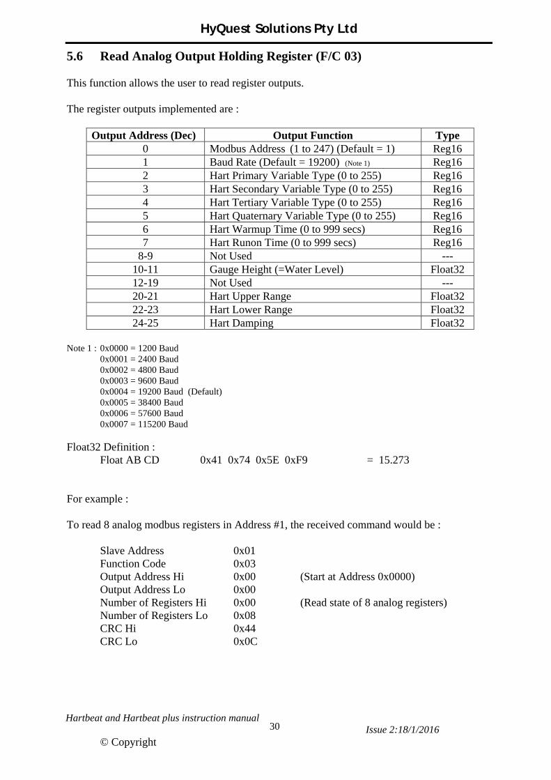
5.6 Read Analog Output Holding Register (F/C 03) This function allows the user to read register outputs. The register outputs implemented are :
Output Address (Dec) Output Function Type 0 Modbus Address (1 to 247) (Default = 1) Reg16 1 Baud Rate (Default = 19200) (Note 1) Reg16 2 Hart Primary Variable Type (0 to 255) Reg16 3 Hart Secondary Variable Type (0 to 255) Reg16 4 Hart Tertiary Variable Type (0 to 255) Reg16 5 Hart Quaternary Variable Type (0 to 255) Reg16 6 Hart Warmup Time (0 to 999 secs) Reg16 7 Hart Runon Time (0 to 999 secs) Reg16
8-9 Not Used --- 10-11 Gauge Height (=Water Level) Float32 12-19 Not Used --- 20-21 Hart Upper Range Float32 22-23 Hart Lower Range Float32 24-25 Hart Damping Float32
Note 1 : 0x0000 = 1200 Baud 0x0001 = 2400 Baud 0x0002 = 4800 Baud 0x0003 = 9600 Baud 0x0004 = 19200 Baud (Default) 0x0005 = 38400 Baud 0x0006 = 57600 Baud 0x0007 = 115200 Baud Float32 Definition :
Float AB CD 0x41 0x74 0x5E 0xF9 = 15.273 For example : To read 8 analog modbus registers in Address #1, the received command would be : Slave Address 0x01 Function Code 0x03 Output Address Hi 0x00 (Start at Address 0x0000) Output Address Lo 0x00 Number of Registers Hi 0x00 (Read state of 8 analog registers) Number of Registers Lo 0x08 CRC Hi 0x44 CRC Lo 0x0C

HyQuest Solutions Pty Ltd
Hartbeat and Hartbeat plus instruction manual Issue 2:18/1/2016
© Copyright
31
The reply to this command would be : Slave Address 0x01 Function Code 0x03 Byte Count 0x10 (16 data bytes to follow) Data Hi 0x00 (Modbus Address = 1) Lo 0x01 Data Hi 0x00 (Baud Rate = 4 (19200)) Lo 0x04 Data Hi 0x00 (Hart PV = 4) Lo 0x04 Data Hi 0x00 (Hart SV = 0) Lo 0x00 Data Hi 0x00 (Hart TV = 2) Lo 0x02 Data Hi 0x00 (Hart QV = 3) Lo 0x03 Data Hi 0x00 (Warm Up = 60 secs) Lo 0x3C Data Hi 0x00 (Run On = 10 secs) Lo 0x0A CRC Hi 0x19 CRC Lo 0x26

HyQuest Solutions Pty Ltd
Hartbeat and Hartbeat plus instruction manual Issue 2:18/1/2016
© Copyright
32
5.7 Write a Single Analog Output Register (F/C 06) This function allows the user to write a single register output. The registers allowed are described in F/C 03 For example : To write 4 to the Primary Variable in Address #1, the Rx command would be : Slave Address 0x01 Function Code 0x06 Output Address Hi 0x00 (Start at Address 0x0002) Output Address Lo 0x02 Data Hi 0x00 (Set Primary Variable to 4) Lo 0x04 CRC Hi 0x29 CRC Lo 0xC9 The reply to this command is an echo, that is : Slave Address 0x01 Function Code 0x06 Output Address Hi 0x00 (Start at Address 0x0002) Output Address Lo 0x02 Data Hi 0x00 (Set Primary Variable to 4) Lo 0x04 CRC Hi 0x29 CRC Lo 0xC9
HyQuest Solutions Pty Ltd
Hartbeat and Hartbeat plus instruction manual Issue 2:18/1/2016
© Copyright
33
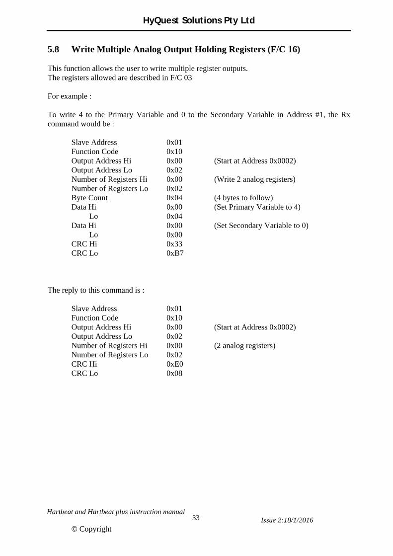
5.8 Write Multiple Analog Output Holding Registers (F/C 16) This function allows the user to write multiple register outputs. The registers allowed are described in F/C 03 For example : To write 4 to the Primary Variable and 0 to the Secondary Variable in Address #1, the Rx command would be : Slave Address 0x01 Function Code 0x10 Output Address Hi 0x00 (Start at Address 0x0002) Output Address Lo 0x02 Number of Registers Hi 0x00 (Write 2 analog registers) Number of Registers Lo 0x02 Byte Count 0x04 (4 bytes to follow) Data Hi 0x00 (Set Primary Variable to 4) Lo 0x04 Data Hi 0x00 (Set Secondary Variable to 0) Lo 0x00 CRC Hi 0x33 CRC Lo 0xB7 The reply to this command is : Slave Address 0x01 Function Code 0x10 Output Address Hi 0x00 (Start at Address 0x0002) Output Address Lo 0x02 Number of Registers Hi 0x00 (2 analog registers) Number of Registers Lo 0x02 CRC Hi 0xE0 CRC Lo 0x08

HyQuest Solutions Pty Ltd
Hartbeat and Hartbeat plus instruction manual Issue 2:18/1/2016
© Copyright
34
5.9 Read Device ID (F/C 43) This command allows the user to read the ID of this product. Compliance with the basic category – which is :
Object ID 0 = Vendor Name Object ID 1 = Product Code Object ID 2 = Major / Minor Revision
For example : Slave Address 0x01 Function Code 0x2B MIE Type 0x0E (0x0E Means Device ID) Device ID Code 0x01 (0x01 Request for the Basic ID) Object ID 0x00 (Could be 0x00, 0x01 or 0x02) CRC Hi 0x70 CRC Lo 0x77 The reply would be : Slave Address 0x01 Function Code 0x2B MIE Type 0x0E (0x0E means Device ID) Device ID Code 0x01 Conformity Level 0x01 (0x01 Basic Identification) More Follows 0x00 (0x00 no more objects avail) Next Object ID 0x00 (0 because More Follows was 0) Number of Objects 0x03 (3 objects to follow) Object ID 0x00 (0x00 Vendor Name) Object Length 0x15 (21 character string) Object Value Hydrological Services (ascii string) Object ID 0x01 (0x01 Product Code) Object Length 0x08 (13 character string) Object Value HartBeat (ascii string) Object ID 0x02 (0x02 Major/Minor Revision) Object Length 0x05 (5 character string) Object Value V1.00 (ascii string) CRC Hi 0x20 CRC Lo 0xB3
HyQuest Solutions Pty Ltd
Hartbeat and Hartbeat plus instruction manual Issue 2:18/1/2016
© Copyright
35
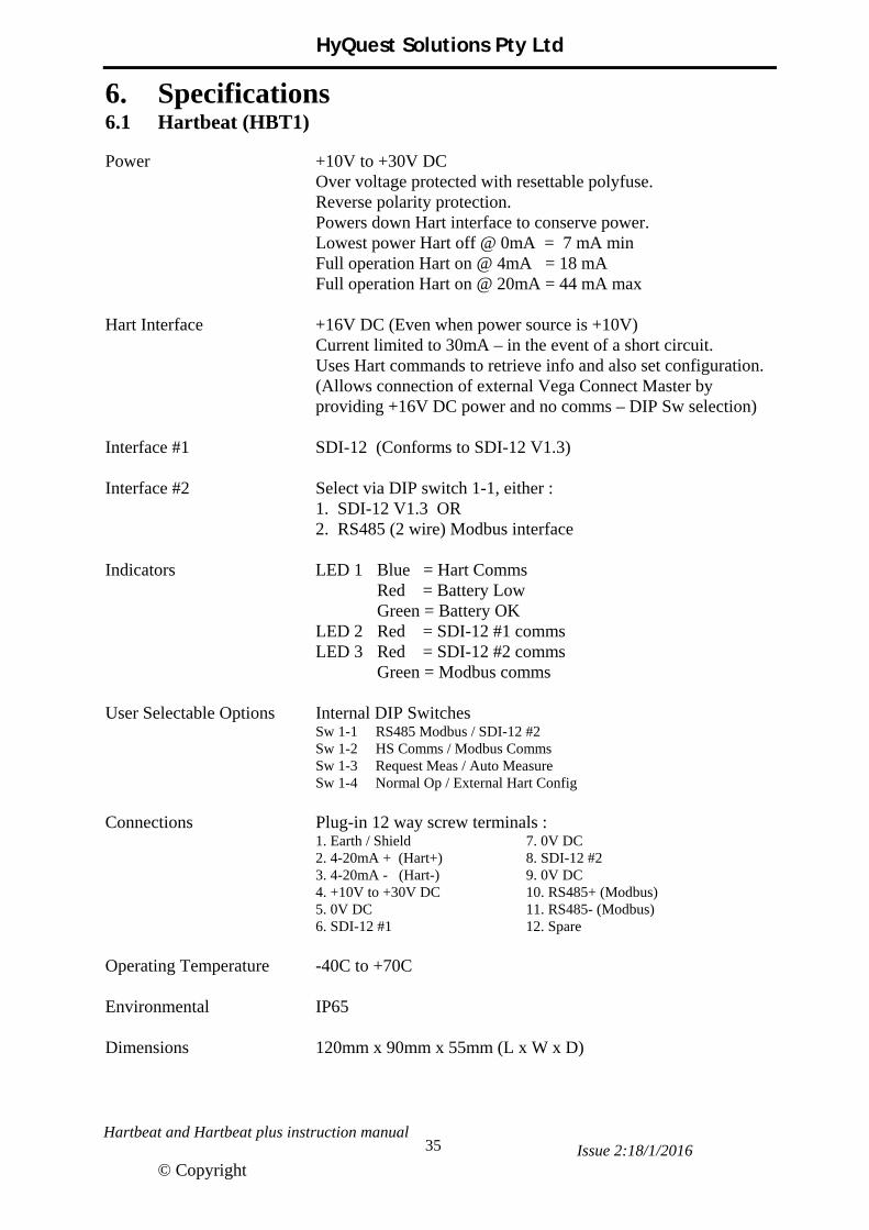
6. Specifications 6.1 Hartbeat (HBT1) Power +10V to +30V DC Over voltage protected with resettable polyfuse. Reverse polarity protection. Powers down Hart interface to conserve power. Lowest power Hart off @ 0mA = 7 mA min Full operation Hart on @ 4mA = 18 mA Full operation Hart on @ 20mA = 44 mA max Hart Interface +16V DC (Even when power source is +10V) Current limited to 30mA – in the event of a short circuit. Uses Hart commands to retrieve info and also set configuration.
(Allows connection of external Vega Connect Master by providing +16V DC power and no comms – DIP Sw selection)
Interface #1 SDI-12 (Conforms to SDI-12 V1.3) Interface #2 Select via DIP switch 1-1, either :
1. SDI-12 V1.3 OR 2. RS485 (2 wire) Modbus interface Indicators LED 1 Blue = Hart Comms Red = Battery Low Green = Battery OK LED 2 Red = SDI-12 #1 comms LED 3 Red = SDI-12 #2 comms Green = Modbus comms User Selectable Options Internal DIP Switches Sw 1-1 RS485 Modbus / SDI-12 #2 Sw 1-2 HS Comms / Modbus Comms Sw 1-3 Request Meas / Auto Measure Sw 1-4 Normal Op / External Hart Config Connections Plug-in 12 way screw terminals : 1. Earth / Shield 7. 0V DC 2. 4-20mA + (Hart+) 8. SDI-12 #2 3. 4-20mA - (Hart-) 9. 0V DC 4. +10V to +30V DC 10. RS485+ (Modbus) 5. 0V DC 11. RS485- (Modbus) 6. SDI-12 #1 12. Spare Operating Temperature -40C to +70C Environmental IP65 Dimensions 120mm x 90mm x 55mm (L x W x D)

HyQuest Solutions Pty Ltd
Hartbeat and Hartbeat plus instruction manual Issue 2:18/1/2016
© Copyright
36
6.2 Hartbeat Plus (HBT1 Plus) Power +10V to +18V DC Reverse polarity protection. LCD off + Backlight off + Hart on @ 4mA = 32mA min LCD on + Backlight on + Hart on @ 20mA = 118mA max Hart Interface +16V DC (Even when power source is +10V) Current limited to 30mA – in the event of a short circuit. Uses Hart commands to retrieve info and also set configuration.
(Allows connection of external Vega Connect Master by providing +16V DC power and no comms – DIP Sw selection)
Main SDI SDI-12 (Conforms to SDI-12 V1.3) Extra SDI SDI-12 (Conforms to SDI-12 V1.3) 4-20mA As a sensor - Range configurable Indicators LCD 16 character x 2 line
(Internal) LED 1 Blue = Hart Comms Red = Battery Low Green = Battery OK LED 2 Red = SDI-12 #1 comms LED 3 Green = LCD Board comms User Selectable Options Internal DIP Switches Sw 1-1 Preset off RS485 Sw 1-2 Preset off HS Comms Sw 1-3 Preset on Auto Measure Sw 1-4 Select Normal Op / External Hart Config Connections Plug-in 6 way spring term : Plug-in 3 way screw term : 1. 4-20mA Sensor - 1. Shield 2. 4-20mA Sensor + 2. 4-20mA + (Hart+) 3. Extra SDI-12 #2 3. 4-20mA - (Hart-) 4. 0V DC 5. Main SDI-12 #1 6. +10V to +18V DC Operating Temperature -40C to +70C Environmental IP65 Dimensions 205mm x 100mm x 105mm (L x W x D)

HyQuest Solutions Pty Ltd
Hartbeat and Hartbeat plus instruction manual Issue 2:18/1/2016
© Copyright
37
Appendix A Hart Protocol Description
A.1 Dynamic Variables Hart devices return four Dynamic Variables : 1. Primary Variable (PV) 2. Secondary Variable (SV) 3. Tertiary Variable (TV) 4. Quaternary Variable (QV) As the name “Dynamic Variable” indicates, each one can be assigned to a different variable within the sensor. For example, the Vega WL61 has 5 variable types that can be assigned to any of the four Dynamic Variables : 0 = Distance to the Water (m or ft) 1 = Level as a percentage value (%)
2 = Linearised percentage value (%) 3 = Scaled measured value 4 = Water Depth (m or ft) Water Depth = Lower Range - Distance to the Water (Hart Parameter) (Measured by the Radar) NOTE : The Hartbeat PV should be set to the “water depth” variable type and the Hartbeat SV should be set to the “distance to the water” variable type.
The ‘Upper Range’ is a Hart parameter used by the sensor to calculate the % variables.
The ‘Lower Range’ is a Hart parameter used by the sensor to calculate the Water Depth and the % variables.
Radar
Distance to the water (what the
radar measures)
Water Depth
Lower Range
Upper Range
Hart Parameters

HyQuest Solutions Pty Ltd
Hartbeat and Hartbeat plus instruction manual Issue 2:18/1/2016
© Copyright
38
A.2 Hart Commands The Hart protocol commands are split into 3 main categories : 1. Universal commands (Command 0 to Command 30) 2. Common Practice commands (Command 32 to Command 121) 3. Device Specific commands – unique to a manufacturer’s sensor (Command 128 to 253) Each Command has the basic format :
Delimiter Address Expansion Command Byte Count [Data] Check Byte
The details of the commands can be found in the Hart Protocol Specification documents HCF_SPEC-99.pdf, HCF_SPEC-127.pdf and HCF_SPEC-151.pdf. Hartbeat Hart Command Used The specific Hart commands the Hartbeat use to communicate with the Hart device are : (Note : Variables with ** are used by the Hartbeat) Command 0 : Read Unique Identifier. Returns : Manufacturer ID Device Type No of preambles Device + S/W + H/W Revision Unique Device ID ** Command 3 : Read Loop Current and Dynamic Variables **
Returns : Primary Variable Loop Current measured in mA ** Primary Variable units code ** Primary Variable ** Secondary Variable units code ** Secondary Variable ** Tertiary Variable units code ** Tertiary Variable **
Quaternary Variable units code ** Quaternary Variable ** Command 15 : Read Device Information Returns : PV Alarm Selection Code PV Transfer Function Code PV Upper and Lower Range units code PV Upper Range Value ** PV Lower Range Value ** PV Damping Value ** Write Protect Code Private Label Distributor Code PV Analog Channel Flags
HyQuest Solutions Pty Ltd
Hartbeat and Hartbeat plus instruction manual Issue 2:18/1/2016
© Copyright
39
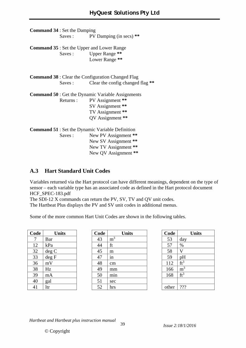
Command 34 : Set the Damping Saves : PV Damping (in secs) ** Command 35 : Set the Upper and Lower Range Saves : Upper Range ** Lower Range ** Command 38 : Clear the Configuration Changed Flag Saves : Clear the config changed flag ** Command 50 : Get the Dynamic Variable Assignments Returns : PV Assignment ** SV Assignment ** TV Assignment ** QV Assignment ** Command 51 : Set the Dynamic Variable Definition Saves : New PV Assignment ** New SV Assignment ** New TV Assignment ** New QV Assignment ** A.3 Hart Standard Unit Codes Variables returned via the Hart protocol can have different meanings, dependent on the type of sensor – each variable type has an associated code as defined in the Hart protocol document HCF_SPEC-183.pdf The SDI-12 X commands can return the PV, SV, TV and QV unit codes. The Hartbeat Plus displays the PV and SV unit codes in additional menus. Some of the more common Hart Unit Codes are shown in the following tables.
Code Units Code Units Code Units 7 Bar 43 m3 53 day 12 kPa 44 ft 57 % 32 deg C 45 m 58 V 33 deg F 47 in 59 pH 36 mV 48 cm 112 ft3 38 Hz 49 mm 166 m3 39 mA 50 min 168 ft3 40 gal 51 sec 41 ltr 52 hrs other ???