Embed Size (px)
Citation preview
HAZARDOUS WASTE MINIMIZATIONGUIDE FOR SHIPYARDS
January 1994
prepared and submitted by:
National Steel and Shipbuilding Co.San Diego, California
Task No. N1-90-2
Report Documentation Page Form ApprovedOMB No. 0704-0188
Public reporting burden for the collection of information is estimated to average 1 hour per response, including the time for reviewing instructions, searching existing data sources, gathering andmaintaining the data needed, and completing and reviewing the collection of information. Send comments regarding this burden estimate or any other aspect of this collection of information,including suggestions for reducing this burden, to Washington Headquarters Services, Directorate for Information Operations and Reports, 1215 Jefferson Davis Highway, Suite 1204, ArlingtonVA 22202-4302. Respondents should be aware that notwithstanding any other provision of law, no person shall be subject to a penalty for failing to comply with a collection of information if itdoes not display a currently valid OMB control number.
1. REPORT DATE JAN 1994
2. REPORT TYPE N/A
3. DATES COVERED -
4. TITLE AND SUBTITLE Hazardous Waste Minimization Guide for Shipyards
5a. CONTRACT NUMBER
5b. GRANT NUMBER
5c. PROGRAM ELEMENT NUMBER
6. AUTHOR(S) 5d. PROJECT NUMBER
5e. TASK NUMBER
5f. WORK UNIT NUMBER
7. PERFORMING ORGANIZATION NAME(S) AND ADDRESS(ES) Naval Surface Warfare Center CD Code 2230 - Design Integration TowerBldg 192 Room 128 9500 MacArthur Blvd Bethesda, MD 20817-5700
8. PERFORMING ORGANIZATIONREPORT NUMBER
9. SPONSORING/MONITORING AGENCY NAME(S) AND ADDRESS(ES) 10. SPONSOR/MONITOR’S ACRONYM(S)
11. SPONSOR/MONITOR’S REPORT NUMBER(S)
12. DISTRIBUTION/AVAILABILITY STATEMENT Approved for public release, distribution unlimited
13. SUPPLEMENTARY NOTES
14. ABSTRACT
15. SUBJECT TERMS
16. SECURITY CLASSIFICATION OF: 17. LIMITATION OF ABSTRACT
SAR
18. NUMBEROF PAGES
104
19a. NAME OFRESPONSIBLE PERSON
a. REPORT unclassified
b. ABSTRACT unclassified
c. THIS PAGE unclassified
Standard Form 298 (Rev. 8-98) Prescribed by ANSI Std Z39-18
PROJECT OVERVIEW
The approach to this project was to identify the general waste stream common to the shipbuilding andrepair industry and assign a priority based on environmental and economic impact of the variouswaste streams. Research was conducted on gathering of available information on on waste reductionfrom industry sources, regulatory agency sources, and general environmental literature. The compiledinformation was evaluated and organized into the various chapters identified from the priority of thevarious waste streams.
The development phases of the guide are summarized below:
9 Survey shipyards to identify the types of waste generated● Prioritize the waste and/or waste stream types● Survey shipyards to identify existing waste minimization techniques being used in the yards by
both public and private for content● Develop a final guide and review for completeness and accuracy.
Ill
TABLE OF CONTENTS
Foreword
Objectives
Project Overview
1. Introduction . . . . . . . . . . . . . . . . . . . . . . . . . . . . . . . . . . . . . . . . . . . . . . . . . . . . . . . . . . . . . . . . . . . . . . . . . . . . . . . . . . . . . . . . . . . . . . . . . . . . . . . . . . . . . . . . . . 1
2. Setting up a Waste Minimization Program 22.1 Introduction 22.2 EIements for a Successful Waste Minimization Program 22.3 Methods for Setting Up a Waste Minimization Program 32.4 Preparing an Evacuation Report 62.5 How to Choose and Implement Waste Minimization Projects 72.6 Treatment and Disposal 10
3. Machining and Other Metalworking Operations 123.1 Introduction 123.2 Waste Streams 123.3 Methods of Waste Reduction 133.4 Waste Fluid Treatment 153.5 Summary 16
4. Solvent Cleaning and Decreasing Operations 174.1 Solvent Source Reduction 174.2 Solvent Recycling 214.3 Solvent Treatment and Pretreatment 274.4 Summary 31
5. Metal Plating and Surface Finishing 325.1 Introduction 325.2 Process Description 325.3 Waste Stream from Plating Operations 345.4 Source Reduction 355.5 Recycling 425.6 Treatment 45
6. Painting and Coating Operations 476.1 Introduction 476.2 Application Equipment 476.3 Alternative Coatings 496.4 Good Operating Practices 506.5 Recycling 536.6 Treatment 536.7 Summary 53
iv
7.
8.
9.
10.
11.
12.
13.
14.
15.
TABLE OF CONTENTS (continued)
Surface Preparation 547.17.27.37.4
Vessel8.18.28.38.48.5
Abrasive Blasting 54Chemical Stripping 55Mechanical Stripping 56Summary 56
Cleaning 57Introduction 57Tank Washing Operations 58Chemical Cleaning 58Engine Room Cleaning Method 59Tank Cleaning Waste Water Treatment 59
Photographic Processes 61Introduction 61
9.2 Sources of Waste 619.3 Waste Management 63
9.4 Waste Reduction 63
9.5 Summary 64
Lubricants and Used Oil 6610.1 Introduction 6610.2 Description of Process Operations Which Use Lubricants 6710.3 Source Reduction or Minimization 6810.4 On-Site Recycling and Resource Recovery 6910.5 Off-Site Recycling and Treatment 7210.6 Factors in Selecting a Treatment Option 74
Fiberglass Reinforced Construction Operations 7511.1 Introduction 7511.2 Recreational and Commercial Shipbuilding Manufacturers 7511.3 Source Reduction 7711.4 Recycling and Resource Recovery 7911.5 Treatment 79
Waste Minimization Information and Education 8181
12.2 Pollution Prevention Information Sources 8112.3 State Reduction Programs 8112.4 Educational Material and Classes 82
References 83
Definition of Terms and Acronyms 85
Pollution Prevention Bibliography 86
v
1. INTRODUCTION
Historically, shipyards have relied on hazardouswaste Iandfils and treatment of hazardouswaste to address the environmental solutionafter the point of the waste generation. Thisapproach, commonly known as “end of pipe”management, has been based on command andcontrol regulations that rarely offered the ship-yard positive incentives to reduce waste. Thisapproach has been successful and has con-tributed to an overall improvement of our envi-ronment.
Recently, however, the EPA and the rest of thenation have undergone a philosophical changein which environmental protection is increas-ingly viewed as an opportunity to prevent thegeneration of pollutants at the source (sourcegeneration). The advantage of this approach isthat preventing pollution at its source help ship-yards avoid many costs and potential liabilitiesassociated with treatment, storage, transporta-tion, and disposal. The EPA and the nation havedesignated pollution prevention as a top priori-ty. This approach to environmental protectionbecame a national policy when the Presidentsigned into law the Pollution Prevention Act of1990.
Pollution prevention encompasses any practicethat reduces or eliminates the quantity and/ortoxicity of pollutants through source reduction.As defined in the Pollution Prevention Act of1990, source reduction is:
“Any practice that reduces the amount of anyhazardous substance, pollutant or contaminantentering the waste stream or otherwise releasedinto the environment (including fugitive emis-sions) before recycling, treatment, or disposal;and reduces the hazards to pubic health and theenvironment associated with the release of suchsubstances, pollutants, or contaminates.”
1
This Hazardous Waste Minimization Guide forShipyards is an attempt to address this transi-tion from “end of pipe” solution to a sourcereduction philosophy.
2. SETTING UP A WASTE MINIMIZATION PROGRAM
2.1 Introduction
A waste minimization program is a forwardlooking approach to waste management that isboth systematic and responsive. It is organizedfor future problems as it solves the currentones within a shipyard.
The problem of waste is first a problem of pro-duction efficiency. A Waste MinimizationProgram examines a waste stream to increaseproduction efficiency at the yard whiledecreasing waste generation. The program hasto be looked at as part of the shipyard’s overallmanagement strategy. This section will explainthis management strategy and how it willreduce generation of hazardous waste in thefuture.
2.2 Elements for a Successful MinimizationProgram
Top Management Supports the Program
For a successful program, support must beprovided at a high enough management levelto influence the operation and environmentalpolicy decision. Without this support, mostminimization programs fall apart due to thelack of proper funding or key production per-sonnel needed for many waste minimizationprojects.
Employees Incentive Program
Most successful minimization programs haveincentive programs for submitting ideas onwaste minimization. These ideas are only use-ful ideas if they are successfully implementedand maintained. The incentive program shouldreward those who originate the ideas. Rewardand recognition should be given to the individ-ual who does the hard work of implementationof the project. By publicizing the reward andrecognition, other workers will be inspired to
2
submit their ideas on waste minimization. Anexample of an incentive program is to use thecompany’s suggestion program as a vehicle tostart a reward program. The company newspa-per or an environmental newsletter can beused to publicize the waste minimization pro-gram and the successful ideas submitted to thesuggestion program.
Shipyard Personnel Involvement in Program
As with any successful program, the shipyardpersonnel must be involved in the design andinstallation of any idea. This helps in the gen-eration of additional ideas and inspires them toadopt the changes to the operation. Since theshipyard personnel operate and maintain theoperations undergoing the change, these peo-ple should have a say in the changes so that itwill meet their needs.
A Leader is Needed to Implement the Project
Many successful programs are led by a leaderwho strongly believes in the project and canovercome the development and start-up prob-lems associated with a waste minimizationproject. If the project is led by an individualwho does not believe in the project, the projectis a failure from the beginning.
Increase in Productivity and Reduced CostThrough Implementation of the Program
Examine a project that can result in a reduc-tion in production cost and increase productionyield or production quality. Reducing the costof an individual department is more likely tohave upper management support than a projectwhich is shared company-wide, as are manyreductions in waste disposal cost projects. Aproject that can reduce personnel require-ments, thus increasing productivity, will give astrong incentive for change.
Waste Disposal Cost Should be Charged toDepartment Within Shipyard Operation
At shipyards that have done successful wasteminimization projects, shipyard operatingdepartments were aware of the true cost of thehazardous waste disposal and considered thosecosts when making a decision on the imple-mentation of the project.
Shipyard Employees Appreciate theEnvironmental Benefits of Waste Disposal
Most shipyard employees are motivated by thedesire not to pollute the environment in whichthey work and possibIy live. By educating theemployees on the effects of pollution, mostemployees will be motivated to be more care-ful.
Training Shipyard Employees on NewEnvironmental Product or Equipment
Many minimization projects require newequipment or products and require operators tohave training on the use of such equipment orproducts. Successful projects require suchtraining to guarantee that the equipment orproduct will be used properly and will receivethe proper maintenance or support for the con-tinuing success of such equipment or products.
Assurance of Proper Operation of Equipmentat Shipyard
Care must be taken to ensure that any new mod-ification of equipment be tested before beingtransferred to the yard. Be sure to solicit sugges-tions or advice from other users before buyingany equipment to ensure that the equipment willoperate to the specifications of the shipyard.
New Equipment is Reliable, Simple toOperate, and Maintain
Most modifications are successful due to thefact that the new equipment is straightforward
3
and simple to operate, thus requiring minimaltraining to key personnel and low maintenancerequirements. If this does not happen, mostoperations resort back to the old methods ofoperation.
2.3 Methods for Setting Up a SuccessfulWaste Minimization Program
Planning a Wrote Minimization Program asPart of the Company Overall Goal
Many shipyard production workers are usuallyevaluated on meeting a production goal orproduct quality. If a shipyard encourages itsemployees to make waste reduction a part oftheir daily duty, the employees will realize theimportance of the program. The importance ofthe program must be real and should be part ofthe job performance evaluation for the individ-ual employee. The top management must sup-port this concept and not be promoted solelyby the Environmental Department of the ship-yard.
Establishing of a Waste Minimization onOfficial for the Shipyard
An individual with environmental complianceexpertise should be appointed to oversee thewaste minimization program and to make surethat environmental effects are as important asproduction.
Taking an Inventory of Waste MinimizationProject by Shipyard Departments
As much as possible, waste generation shouldbe measured and listed by individual depart-ments so the shipyard can evaluate the individ-ual projects to determine which waste mini-mization effort should receive the most con-centration.
Ranking Waste Minimization Efforts by Costof Disposal
A shipyard should use waste generation datato help identify production areas which havean exceptionally high or low waste generationrate. This data allows shipyards to invest inwaste minimization efforts where they canhave the most potential for being cost effec-tive.
Charge Departments for Waste Disposalcosts
Charging a shipyard department for the dis-posal cost will force a department to budgetfor the waste cost and allow for the departmentto implement methods for waste minimizationto reduce this cost within the department.
Provide a Capital Investment Budget forWaste Minimization Projects
In many cases a waste minimization projectcannot be justified on waste minimizationeffort alone and needs the combined benefit ofa production capital improvement budget forthe waste minimization project to receive theneeded funding.
Publicize the Successes and Learn from theFailures
By giving recognition to a successful projectyou will motivate other employees within theshipyard to participate in the program and toreceive a reward if their idea or project isselected. You may want to publicize projectsthat are not successful to educate others so thatthe same idea is not repeated.
Encourage the Transfer of Technology
A shipyard should encourage the transfer ofsuccessful waste minimization methods withinits organization so that other organizations can
share in the success and reduce their opera-tional cost.
Conducting a Waste MinimizationAudit
A waste minimization program will not besuccessful unless a detailed study of the vari-ous waste stream is undertaken. The first stepin a waste minimization project is to obtaindetailed information of the operation by doinga waste audit. A waste audit is similar to anenvironmental audit but the major difference isthat an environmental audit is to see that theshipyard is in environmental compliance withenvironmental regulations. A shipyard con-ducts a waste audit to see how it can preventor reduce the generation of waste.
Identify Shipyard Operations
All manufacturing processes must be identi-fied by the function of the process and how itsoperation is related to the overall repair orconstruction process of the shipyard. After thedetailed record has been completed, processflow diagrams representing the interconnec-tions of the various operations of the shipyardshould be drafted, including ship repair andnew construction.
Collect Data
Collection of information about the chemicals,raw materials, inventory of hazardous materi-als, and waste water usage survey is necessary.This information can be obtained from thecompany purchasing records or through actualmeasurements. The data may need to be reviewedto correct for fluctuations in production.
Collect Raw Material Inventory
A detailed record should be kept of the rawmaterials that are purchased and the quantitiesbeing used in the various departments within
the shipyard. With this type of information, atracking of any lost material can be calculated.The areas can be identified and steps can betaken to minimize loss during handling or stor-age of the materials. Purchasing practicesshould be examined if high inventories resultin spoilage or off-spec material.
Conduct Waste water Survey
A great savings can be achieved by reducingand controlling the water usage. Using lesswater will result in less waste water needingtreatment. The increased concentration of thecontaminates will result in increased efficien-cy of most pollution control equipment. Tobegin this saving, the shipyard must do awastewater survey that provides the following:
The
An understanding of the specific sourcesand flow within the shipyard.
An understanding of the fluctuation thatoccurs in both content and quantity of theshipyard wastewater.
information provided by the survey willbe invaluable when evaluating in-plant controlof wastewater generation.
Track Waste
It is important to know how much of each typeof waste is being taken off-site for treatmentand disposal. A review of the manifest willprovide this information. Information aboutthe generator or satellite storage area shouldbe recorded so that waste minimization effortcan identify the best approach to reduce thesewaste streams.
Conduct Material Balance
This type of assessment is based on the princi-ple that the total material entering a processmust equal the total material that eventually
5
leaves the process or operation. In most casesthis type of study is extremely time consumingand is required when there is a significant con-cern about a certain waste stream.
EvaIuate Options
After data has been collected and summarized,the department or team can begin the evalua-tion of the waste minimization options. Thisinvolves the selection of specific wastestreams which have been targeted for wasteminimization. The department or team willdetermine which methods will be used toreduce the waste stream.
Factors that should be considered for selectingwaste minimization methods include the fol-lowing
●
●
●
It is
Implementation cost
Risks involved
Future government regulations.
important to pay attention to complianceand environmental regulations. Such issues arebound to become more strict as environmentalissues continue to be added to legislative agen-das. Due to these issues, it would make senseto aim for a degree of reduction that wiIl keeppace with the current andrequirements.
Identify Low Cost Options
future regulatory
A waste minimization program should bestarted with projects that are easy and inexpen-sive to introduce. Examples are listed below.
● Improved housekeeping procedures byexamining for leaks or taking other mea-sures
● Conduct mass balance assessment ofareas in which unusual losses are spotted.
● Substitute nontoxic or less toxic materialwhen possible for raw materials that ulti-mately become hazardous waste.
✎ Separate hazardous waste streams fromnonhazardous waste streams.
Select Options for Further Study
Some waste reduction options may requiremore detailed analysis, especially if newequipment is needed. In such cases, companiesthat are currently using such equipment shouldbe contacted to learn about any problems andhow to deal with them. The company using theequipment will know about the maintenancerequirements and what to do if breakdownoccurs.
2.4 Prepare an Evaluation Report
After a department or team has completed awaste audit and has evaluated the optionsavailable to the shipyard, the next step is toprepare an evaluation report for the uppermanagement. After the review of the report,management can set an agenda for implemen-tation of waste reduction measures.
The report should contain four main areas ofconcentration:
1. Waste audit summary2. Technical analysis3. Economic analysis4. Regulatory analysis.
Waste Audit Sumnary
The waste audit summary should present allthe collected data in a detailed and easilyunderstandable format. The following itemsshould be covered:
✎ Flow diagrams to show processes andsource of specific waste streams.
✎ Descriptions of each waste stream gener-ated as to its characteristics, quantity gen-erated, method and cost of disposal, andassociated health, safety, and environ-mental concerns.
Technical Analysis
The technical analysis should be forced onspecific recommendations on waste reductionoptions, including advantages and guidelinesfor implementation.
●
✎
●
●
●
●
●
●
●
Include flow diagram of shipyard manu-facture processes, including proposedmodification.
Describe each proposed project in detailwhether capital intensive or low cost.
List advantages of technology selectedover other technologies.
Give a detailed assessment of each tech-nology’s track record.
Outline equipment requirements, includ-ing expected maintenance and laborcosts.
Give information on the ranges of condi-tions that the new equipment will effec-tively operate within.
Explain how the new equipment will helpbring the company into compliance withgovernment regulations.
Give examples on how new equipmenthas helped other companies.
Give an appraisal of what is expectedduring installation of equipment. Giveexamples of an evaluation of safety andreliability factors.
Economic Analysis
The economic analysis should focus on thecost and saving associated with the implemen-tation of the proposed waste minimization pro-gram.
● Give total capital cost and expected costsor savings related to the changes in labor,raw materials and related waste manage-ment requirements.
● Give the potential effects on the produc-tion operation and the production quality.
● Estimate the potential return on invest-ment for the waste minimization projects.
● Give the estimated payback period foreach project.
● Estimate the total costs and savings asso-ciated with the present waste manage-ment policy and the project savings withvarious waste minimization projects sothat comparisons can be made withpotential waste minimization alternatives.
Regulatory Analysis
The regulatory analysis should address theenvironmental concern raised by the federal,state, and local agencies in which the shipyardoperates.
OutIine various federal regulations with whichair, water and hazardous waste dischargesmust comply.
Assess any community concerns that may havebeen expressed about the company’s practicesand how these concerns can be addressedthrough the waste reduction proposals.
7
Additional Information on WasteMinimization Audit
For additional information, the EPA has pub-lished a manual called the Waste MinimizationOpportunity Assessment Manual which can beobtained from the Pollution PreventionClearinghouse which is discussed in Chapter12.2. The NSRP report #345, “EnvironmentalCompliance Inspection Checklist” includes achecklist for waste minimization audit forshipyards which can aid shipyard personnel inconducting an audit. The report can beobtained from the NSRP PublicationCoordinator, UMTRI, 2901 Baxter Road, AnnArbor, Michigan 48109 (313-763-2465).
2.5 How to Choose and Implement WasteMinimization Projects
Once the department or team has reviewed thedata obtained through the waste audit and con-sidered the options outlined in the evaluationreport, the next step is to develop a strategy forthe implementation of the Waste MinimizationProgram. The available options for minimiza-tion are listed in the following order of priority:
1. Elimination2. Reduction3. Reuse4. Recycling5. Treatment6. Disposal.
The higher the option is on the list the betterthe option is for the shipyard and the environ-ment. In the majority of cases, it is virtuallyimpossible to eliminate completely the pro-duction of waste, but it is possible to eliminatecertain waste streams. When elimination is notpossible reduction in volume or toxicity of awaste is the next best option. In many casesreduction is combined with reuse or recycling:
● Reuse when the material is reclaimedfrom the waste stream and put back intothe shipyard process with little or no pro-cessing.
● Recycling when material is reclaimed andplaced back into the production processafter varying degrees of processing.
All reuse and recycling opportunities shouldbe investigated before traditional “end ofpipe” treatment and disposal technologies areconsidered.
Waste Reduction Techniques
There are four main techniques that are avail-able for reducing the volume of a waste at itssource. These are:
1. Good operating practices2. Material modification/substitution3. Production modification4. Production changes.
When considering these options, be ready toassess all aspects of their implementation.
Good Operating Practices The most frequent-ly used method is to improve operating andhousekeeping practices. Such improvementsrequire that existing practices be changed, butthis can usually be done inexpensively.Improvements in operating practices usuallyrequire the following:
● Management/employee initiatives
● Allocation of disposal costs
● Improved material handling and storageprocedures
● Waste tracking.
As explained in the section on successful
8
waste minimization programs, the success of aprogram depends on how fully the employeesaccept the program throughout the shipyard.Employees must be clearly informed as to whytheir participation and cooperation is crucial.Employees must understand that waste reduc-tion is an important part of their job. The over-all objective is to make waste reduction aneveryday part of the job. To make this happenthe shipyard management must remain open toobservations and suggestions from productionpersonnel. Because these employees workwith the operation on a front-line basis, theycan best offer important insight into the wastereduction possibilities.
One simple method of increasing awareness ofthe waste reduction issue is to allocate wastetreatment and disposal costs to the departmentor operation that generates the waste rather thanto a single department or overhead account. Inthis way, each department will squire an appre-ciation of the treatment and disposal costs andwill plan ways to reduce the generation of thiswaste within the department. If the waste is gen-erated by more than one department, the costshould be shared between departments.
In many cases, improvements in waste reduc-tion can be achieved by improving the meth-ods materials are handled or stored. The fol-lowing areas of operations should be examinedto determine if changes should be introduced.
● Handling and storage of raw material(paint, thinners, etc.)
✎ Inventory control (“Just-in-Timen prin-ciples)
● Waste segregation.
The improper handling and storage of rawmaterials and products can result in expensivewaste generation. Leaks and spills can add tosignificant quantities of waste material. The
volume of material stored at the warehousecan have a bearing on the waste generation,particularly when it has a limited shelf life. Anexample is when paint becomes off-spec dueto exceeding the VOC limit as a result of regu-latory agencies lowering the limit. The propercontrol of material inventory can mean thatmaterials may need to be ordered under theJust-in-Time principle so that materials arrivewhen they are needed. This could increasematerial costs but in many cases the disposalrests can exceed the material cost increases.
The treatment and disposal of mixed waste isoften complicated and more expensive thanthe cost of the separated waste and possiblereuse. Methods of collecting and storing wasteshould be examined closely to determine theextent to which waste can be segregated.
The segregation of waste can be greatly aidedby the use of waste tracking. Under this sys-tem waste can be tracked from the point thematerial enters the shipyard to the point itleaves as a waste or product. This type ofinformation gives the waste reduction person-nel the knowledge of how the waste is generat-ed. It also identifies the area where a moreefficient process or reduction should be used.The information for a waste tracking system isobtained by conducting an inventory of rawmaterials, wastes in storage, and waste streamsbeing generated by shipyard operations.
A flow diagram prepared during an auditor asimilar chart of shipyard operations shouldhelp in this tracking process. Materials shouldbe tracked from the point they enter the ship-yard. Therefore procedures should be coordi-nated so that all departments understand whois involved with purchasing, handling, storage,and processing of the material.
With a tracking system in place, the handlingand storage of material can be made more efficient. Procedures can be put in place which
9
will keep waste suitable for reuse or recyclingseparate from those intended for treatment ordisposal. With a proper system detection andprevention of problems before they becomemajor concerns will provide the clearestinsight into ways of correcting problems thatalready exist.
As with any waste reduction program, theproper tracking of the waste wiIl require thefull cooperation and participation of all ofthose invoIved. It is essential that all employ-ees be informed of the importance of the track-ing program and procedures and be given theopportunity to provide suggestion on ways toimprove material handling or storage in anefficient reamer.
Material Modification/Substitution Materialmodification or substitution is a waste reduc-tion option by which certain materials are sub-stituted for other materials to eliminate orreduce hazardous waste generation. Water-based primer, for example, may be usedinstead of solvent-based. If it is not possible touse materials that generate less waste, it maybe possible to use materials that will result inwaste that is less hazardous or more suitablefor reuse or recycling. Material substitutionwill result in fewer treatment and disposalproblems and may result in a price reductionof the raw materiaI.
Production Process Modification It is some-times possible to make operational changesthat wiIl result in waste reduction or in the gen-eration of less waste. These changes caninclude and changes in the production proce-dures, equipment redesign, introduction ofautomation, changes in the operation condi-tions such as temperature, pressure, flow rates,and residence times. Many of these changesmay need large capital investments; therefore,a detailed analysis should be done before anyof the changes are adopted. Usually suchchanges result in better efficiency andincreased quality.
Product Changes Product changes that resultin reduced waste generation can take two dif-ferent forms:
● Product substitution
● Product reformulation.
Product substitution means changing the prod-uct to eliminate the hazardous waste or toreduce the overall amount of waste associatedwith the product. For example, a freon productcan sometimes be replaced by an aerosol prod-uct which is less harmful, or in a containerwhich is released by a pump therefore elimi-nating the need for a chemical propellant.
Product reformulation is the replacement of aningredient in a product or changing the entirecomposition.
Reuse/Recycling
When every effort has been made to reducethe waste, the next step is to see how theremaining waste can be reused or recycled.Recycling means processing or treating thewaste material and using it in one of twoways:
● As a substitute for a virgin raw materialin the same production process. Anexample would be recycling the lubricat-ing base coat used on the shipbuildingsliding ways.
● As a recycled material in a different pro-duction process. An example would bethe use of oil from bilge water separationused as a lubricant in a recycled motor oilproduct.
The waste may be recycled on-site or it maynot be economically feasible to recycle on-sitedue to low concentration of the usable material
10
in the waste. If recycling on-site is not possi-ble it is sometimes possible to send it to anoff-site recycling facility. In some cases it maybe possible to sell the material to another com-pany for its reuse through a waste exchange. Awaste exchange matches up waste generatorswith waste users.
A proper recycling program can result inlower disposal costs and increased operatingefficiency. Disposal should be an optionreserved only for those wastes that cannot berecycled or sold to another company for reuse.
2.6 Treatment and Disposal
Waste that remains after all reduction, reuse,and recycling possibilities have been investi-gated should be considered for detoxificationthrough biological, chemical, or physicalmeans.
Biological waste treatment can be applied onlyto waste that can be biologically degraded.Biological treatment procedures commonlytake place in sewage treatment plants, aeratedlagoons, and through the use of microorgan-isms. These procedures involve the removal ofsludge, which is then dumped in the municipallandfill sites or used on agricultural land asfertilizer. Heavy metals or toxic organic chem-icals, if not removed, can remain in the sludgeand pollute the soil or ground water.
Chemical/Physical Treatment
Chemical and physical methods for treatingwaste uses various technologies ranging fromsimple separations to complex chemical reac-tions. A hazardous waste that has dilute con-centration is usually concentrated, so that asmaller volume can be sent off for disposal.Separation and concentration technologiesinclude ultrafiltration, reverse osmosis, ionexchange, centrifugation, flotation, distillation,
precipitation, and electrolytic filtration amongothers. Detoxification of waste is commonlydone through such methods as chlorine strip-ping, neutralization of acid, and alkalinewaste.
Incineration
The burning of waste is known as thermaldestruction. This waste is normally incineratedat electric plants, rotary cement kilns, or haz-ardous waste incinerators. The process isundertaken either in the presence of oxygen(incineration) or in an oxygen-deficient envi-ronment (pyrolysis).
11
3. MACHINING AND OTHER ME
12
3.1 Introduction
The machining process is the operation thatinvolves a cutting tool or some other type ofabrasive material to shape a piece of metal.The most common types of metal cuttingprocesses are: broaching, cutting, drilling,forging, grinding, milling, planing, polishing,reaming, sawing, shaping, stamping, thread-ing, turning, and more. In most cases, the cut-ting tool travels along the surface of the workpiece and shaves off the metal in front of it.The high friction at the cutting edge of theblade creates heat. If allowed to becomeexcessive, this heat can permanently deformthe part that is being formed, or the cuttingtool. To prevent this undesirable effect, someform of coolant is needed. Usually a liquid issupplied to the leading edge of the blade tocreate a medium with which the heat can bemoved to a coolant sump.
3.2 Waste Streams
The various machining operations performed inshipyards yield a varying array of hazardouswaste. Some of the most common of these arethe waste metalworking fluids, solvents, and oils.
3.2.1 Metalworking Fluids
Metalworking fluids serve many purposes inthe machining process. Their primary use is toremove heat from the cutting area, but theyalso serve to lubricate, inhibit corrosion, helpproduce a good finish, and wash away metalshavings. The coolant fluids account for thelargest waste stream generated by machiningoperations. Waste metalworking fluids arecreated when the fluids are no longer usabledue to contamination by oils or chemical addi-tives. To a certain extent, this contaminationis unavoidable, however; it is possible toreduce the rate at which contamination occurs.
If the contamination rate of the metalworking
TALWORKING OPERATIONS
fluids is reduced, the need to replace them willbe less frequent. This will reduce the wastegenerated.
There are four major types of metalworkingfluids currently used in shipyards: synthetic,semi-synthetic, soluble oil, and straight oil.Straight oil is a 100% petroleum product.Synthetic oil is an oil substitute that does notcontain any actual oil and has the advantage ofbeing less hazardous than the other types.Semi-synthetic oils are a mixture of petroleumand synthetic fluids with approximately 2-30percent of the mixture being petroleum.Soluble oils are soluble in water and tend tocontain between 60-90 percent petroleum.
The most widely used metalworking fluids aresoluble oils. They are often the least expen-sive because they are frequently diluted toratios of 15:1 or higher. However, the processof watering the concentrate will also lead tohigh fluid maintenance requirements becausethe fluid will not perform properly unless it isat the correct concentration.
The major contaminants found in metalwork-ing fluids consist of: hydraulic oils, lubricat-ing oils, phenols, creosol, alkalies, phosphoruscompounds, and chlorine. These are also theconstituents that require the waste fluids to behandled as hazardous waste.
A frequent problem encountered with metal-working fluids is rancidity. This is caused bybacterial breakdown of the fluid and it leads toa less effective product as well as a foulsmelling work station. The odors can becomestrong enough that it alone will warrant chang-ing the machine’s fluid.
Maintenance of metalworking fluids isextremely important. When using water-basedcutting fluids, it is crucial to maintain theproper “concentrate to water” ratio for properperfomance.
Solvents
Solvents are used to clean machinery parts andcan be a substantial component of the machin-ing process waste stream. The amount of sol-vent waste is highly dependent on the qualityof cleanliness desired. For example, if themetal is going to be plated with zinc, it is notnecessary to achieve a high degree of cleanli-ness because the cyanide-zinc bath is knownto have good cleaning properties itself. Insome cases, more than one solvent must beused to properly clean the part, and a sequenceof steps involving acids, abrasive, and othersubstances may be needed. The importance ofsolvent waste reduction can not be overempha-sized. Methods of reducing solvent waste arediscussed in more detail in Chapter 4.
Tramp Oil
The largest contaminant in cutting fluids istramp oil. Tramp oils are lubricating orhydraulic oils that leak into the coolantthrough defective gaskets or other malfunc-tioning seals. The presence of tramp oils in ametalworking fluid will prevent the fluid fromcooling as effectively as it should, decrease thelubricating properties, and increase the amountof smoke and oil mist emitted from themachine. Most significantly, a cooling fluidcontaminated with tramp oil will degradequickly due to bacterial growth. This leads torancidity.
Hydraulic oil is the constituent that most con-tributes to rancidity; in part because it is oftenmore miscible in coolant fluid than lubricatingor machine oils are. Lube and machine oilswill usually float to the surface of the sumpwhere it can be skimmed off.
Metal Cuttings
Not all of the metal cuttings from machineryoperations are considered hazardous. In fact,
13
it is usually required to classify scrap metaI ashazardous only if it has been contaminatedwith waste fluid. This is frequently the casewhen the metalworking fluid is used to spraymetal shavings away from the cutting edge ofthe blade.
3.3 Methods of Waste Reduction
Several options are available to reduce wastefrom the machine shop. From mechanicalchanges to good operating practices, somemethods of waste reduction should be utilized.
Inventory and Procedures
The first thing that should be done in anywaste minimization program is to take anaccurate inventory of all the materials and pro-cedures used in the process. Such recordscould be used to ensure that the current activi-ty in the shop complies with local, state, andfederal regulations. Good inventory practiceswill also make it easier to determine whetherthe shop is using more chemicals than itshould require. If possible, the number of flu-ids used should be limited. It is much easier torecycle or dispose of a large quantity of onefluid than smaller quantities of several fluids.
The types of fluids, the quantities used, thecost of each, and how often they are pur-chased, should be recorded. The individual incharge of fluids purchasing should be notifiedof the project. He should be interviewedbecause the input of the workers who use thesefluids every day is more significant than anyother.
Source Reduction
After an inventory of materials and proceduresis completed, the next logical step is to reducewaste by minimizing it at its source. This canbe done by substituting less hazardous materi-als for those that are currently being used, orby modifying processes.
Preventing Fluid Contamination
Fluid can become hazardous waste if it is cont-aminated. Although it is not possible to elimi-nate contamination, it is possible to reduce therate of contamination and thereby prolong itsuse.
The primary contaminant in these waste fluidsis tramp oil. One way to postpone contamina-tion is to promote better maintenance of thewipers and seals. A preventative maintenanceprogram should be installed and enforced inthe machine shop. Scheduled sump andmachine cleaning as well as periodic inspec-tions of the wipers and oil seals should be car-ried out. The responsibility for this should beassigned to some person or group in a positionof authority to ensure its success.
Fluid Selection
The key to fluid selection is to choose the low-est number of varieties possible. This simpli-fies disposal and increases recycling possibili-ties. It may be economically worthwhile topurchase an expensive fluid that is of highquality and is versatile enough to be used in allthe areas of the shop.
Fluid Quality and Testing
Fluid quality is an important concern because alow quality fluid may lead to reduced machinelife and lower product quality. Therefore, it isimportant to have regular testing for contami-nants and concentrations. Tests should also bedone to determine pH level, as well as rust,tramp oil, and suspended solids concentration.The test analysis can alert the operator and pre-ventative measures can be taken. Certain bio-
tides can be added to decrease the rate of bac-terial breakdown but concentrations of thesemust be closely monitored.
14
Synthetic Fluids
Synthetic fluids have many advantages overthe non-synthetic counterparts. Usually thesynthetic varieties do not lubricate as effec-tively, but they are less susceptible to contami-nation and highly resistant to biological break-down. Most synthetic fluids have superiorlongevity and can operate over a large temper-ature range without adverse side effects.Straight oils should be replaced with syntheticones whenever possible.
Gas Cooiants
Applications for using gas as a coolant, ratherthan fluids, are limited. The primary advan-tage of using gas coolants is that the workpiece remains clean. When straight air, whichis the most common, is the gas used there areno toxic emissions or wastes created by theprocess. A gas can also be used in conjunctionwith a fluid to reduce the amount of liquidrequired.
Recycling F1uids
Once all of the source reduction options havebeen considered, it is time to explore the pos-sibilities of reuse. It should be noted that inmany cases, after the majority of the contami-nants have been removed, further treatmentwith chemicals or concentrated fluid is neces-sary before the fluids can be recirculatedthrough the machines.
Filtration
Filtration is a common way to recycle fluids.Many different types of filters can be useddepending on the medium to be filtered andthe amount of filtration desired. Two classesof filtration machines exist, one makes use ofgravity to pull the fluid through the filter, theother utilizes a forced pressure differential.Both types can remove particles from the fluid
as well as tramp oils or other contaminants asrequired.
There are many different methods of filteringThey can be passed through a
bag, disc, or cartridge filter or separated in acentrifuge. When using soluble or syntheticoils, the quality of the mixing water is anextremely important consideration. Waterwith a high mineral content will cause the oilsto break down much more quickly. It is sug-gested that distilled or deionized water beuses.
It is not uncommon to find small debris, suchas gum wrappers or cigarette butts in the oilsumps of these machines. This is clearlyunacceptable and can be prevented by educat-ing the machinists on the importance of sumphygiene. Possibly the best way to prevent thisproblem is to install metal grating over anyopen sumps.
Flotation and Skimming
This is a slow process, but it is inexpensiveand can be very effective. The principle is tolet the fluid sit motionless in a sump or a tank,and after a predetermined amount of time, theunwanted oils are skimmed off the surface andthe heavier particulate matter is collected offthe bottom. Flotation refers specifically to aprocess in which the untreated fluid is putunder high pressure and air is injected into thesolution. When the pressure is released, theair comes out of solution and bubbles to thesurface. As the air becomes gaseous, it attach-es itself to suspended contaminants and carriesthem up to the surface. The resulting sludge isskimmed off the surface and the clean fluid isreused.
Centrifugation
Centrifugation uses the same settling princi-ples as flotation, but the effects of gravity are
15
multiplied thousands of times due to the spin-ning action of the centrifuge. This willincrease the volume of fluids which can becleaned in a given amount of time.
Pasteurization
Pasteurization uses heat treatment to killmicroorganisms in the fluid and reduce therate at which rancidity (biological breakdown)will occur. Unfortunately, heat can alter theproperties of the fluid and render it less effec-tive. Properties lost in this way are usuallyimpossible to recover.
Downgrading
Sometimes it is possible to use high qualityhydraulic oils as cutting fluids. After the oilshave reached their normal usable life, they nolonger meet the high standards necessary forhydraulic components. At this time they arestill good enough to be used for the lessdemanding jobs. It may be necessary to treatthe fluid before it can be reused, but changingfluid’s functions in this manner has provensuccessful in the past.
3.4 Waste Fluid Treatment
After other methods of waste minimizationhave been exhausted, the last option to consid-er is treatment of the waste before shipment.Some less problematic wastes can be suffi-ciently treated to be released to the sewer sys-tem. Others can be diluted to reduce haz-ardousness or the opposite can be done bychanging the waste into a more hazardousmaterial but with reduced volume. Every caseis treated individually so it is very dfficult togeneralize waste fluid treatment.
Ultrafiltration
Ultrafiltration is a specific method of wastefluid concentration. The fluid is separated into

a small amount of highly concentrated waste,and a large portion of minimally toxic wastewater. The concentrated sludge can often besent away to be incinerated or used as fuel,and the waste water may be discharged to asewer.
Chemical Treatment
Chemicals can be used in a holding tank tospeed up the process of oil/water separation.After this type of treatment, the oils will rise tothe surface, the water will fall to the bottom,and a mixed phase solution will be found atthe oil water interface. The top two layers getsent to treatment facilities, and the water maybe discharged to a sewer.
3.5 Summary
Shipyards may realize that it is very cost effec-tive to reduce the amount of machining waste.The most effective means of doing this is toimplement processes that will maintain cool-ing/lubricating fluids to sustain their useful lifefor as long as possible. Through the use ofless hazardous fluids and recycling programs,the cost of disposal of this wastestream can bereduced to negligible amounts.
16


4. SOLVENT CLEANING AND DECREASING OPERATIONS
Due to the nature of the industry, solventcleaning and decreasing operations occur inmany different areas of the shipyard. Sourcereduction, recycling, and treatment should beconsidered as cost-saving options to reduce theamount of solvent waste generated.
4.1 Solvent Source Reduction
To effectively decrease the amount of wastegenerated by solvent cleaning and decreasingoperations, source reduction should be the pri-mary consideration. This section addresses thevarious methods used to eliminate or reducesolvent usage as a means to reduce solventwaste.
Shipyards use solvents in a variety of cleaningand decreasing operations including partscleaning, process equipment cleaning, and sur-face preparation for coating applications.Some of the major solvents used are petroleumdistillates, oxygenated solvents (esters, ethers,ketones, and alcohols), and halogenated sol-vents. The type of solvent used for a processusually depends on the contamination andcomposition of the part being cleaned. Themost common cleaning and decreasing opera-tions include cold cleaning and vapor decreas-ing.
Cold Cleaning Operations
Cold cleaning operations can be divided intofour methods: wipe cleaning, soak or dip tankcleaning, diphase cleaning, and steam gunstripping.
Wipe Cleaning Wipe cleaning consists ofusing a rag or towel that has been dipped orsoaked in solvent to wipe a part or surfaceclean. Wipe cleaning is usually associated withmaintenance operations or processes that fab-ricate parts on a single item basis, such as inthe machine shop. Solvent use tends to be high
17
because to assure cleanliness, a liberal amountof solvent is needed. Disadvantages of wipecleaning include increased air emissions, firehazards, the possibility of lint left on the cleansurface, and the requirement to dispose of therags as hazardous waste.
S o a k c l e a n i n g cons is t s p r imar-ily of soaking parts in a tank of cold solvent orsolvent solution. Small parts are usually han-dled in baskets while larger objects are placedon racks. Heating units may be used to heatthe solvent for a higher degree of cleaningefficiency. Additional efficiency can beobtained by means of agitation. This can beachieved by the installation of a pump andspray unit, use of air sparging, or installationof an ultrasonic unit.
Ultrasonic Cleaning Ultrasonic cleaning relieson the use of high frequency sound waves toproduce cavitation in a solvent cleaning solu-tion. Cavitation results in the formation ofsmall vacuum bubbles that immediately col-lapse after formation. The rapid implosion ofthese bubbles creates a cleaning and scrubbingaction throughout the fluid.
Diphase Cleaning Diphase cleaning combinesa water rinse both before and after the solventcleaning step into one operation. Halogenatedsolvents and water are relatively insoluble sothat when placed together in a tank, they willseparate. The water will float to the top. Thiscauses the parts being cleaned to pass throughthe water bath before reaching the solventbelow. After removal, the parts are rinsed bythe same water. In some systems, a smallpump recirculates the solvent up into a sprayunit. The excess spray and runoff from the partfalls back into the tank and sinks to the bot-tom. The part is then cleaned as mentionedbefore. These systems are usually fullyenclosed to reduce waste due to air emissions.

Steam Gun Stripping Steam gun stripping andcleaning is most often used for removing paintor grease and oil from a metal surface. A mix-ture of non-halogenated solvents can be addedto a storage tank and fed to the steam gun. Aspecial valve controls the amount of solvent sothat the surface can be sprayed with the steamand solvent mixture. Afterwards, it is rinsedwith pure steam. This operation may requirelarge quantities of steam, and it can also gen-erate large amounts ofter.
Vapor Phase Cleaning
Vapor phase cleaning
contaminated rinsewa-
relies on hot solventvapor condensing directly on cold parts insert-ed into the vapor space of the degreaser. Assolvent vapors condense on the dirty parts, thecontaminants are dissolved. The dirty solventfalls to the bottom of the tank is reheated andvaporized, leaving the contaminants behind.As opposed to a soak tank with used solventvapor phase systems maintain their cleaningefficiency because the parts are alwaysexposed to clean solvent vapors.
The potential for air emissions is greater withvapor decreasing operations than that of coldcleaning operations. Emission control is amajor concern to equipment designers forthese systems.
El imination the Use of Solvents
Eliminating the use of solvents avoids anywaste generation associated with spent sol-vent. Elimination can be achieved by utiliza-tion of non-solvent cleaning agents or elimi-nating the need for cleaning altogether.Solvent elimination applications include theuse of water-soluble cutting fluids, protectivepeel coatings, aqueous cleaners, and mechani-cal cleaning systems.
18
Water-soluble Cutting Fluids
Water-soluble cutting fluids can often be usedin place of oil-based fluids. The cutting oilsusually consist of an oil-in-water emulsionused to reduce friction and dissipate heat. Ifthese fluids need to be removed after themachining process is complete, solvents maybe needed.
In efforts to eIiminate solvent decreasing andits subsequent waste, special water-solublecutting fluids have been developed. Systemsare available that can clean the cutting fluidand recycle the material back to the cuttingoperation. Obstacles to implementing thismethod are: cost (water-soluble fluids are gen-erally more expensive), procurement (there areonly a few suppliers available), and the inabili-ty to quickIy switch between fluid types with-out thoroughly cleaning the equipment.
Aqueous Cleaners Aqueous cIeaners, such asalkali, citric, and caustic base, are often usefulsubstitutes for solvents. There are many for-mulations that are suited for a variety of clean-ing requirements. Many aqueous cleaners havebeen found to be as effective as the halogenat-ed solvents that are commonly employed.
The advantages of substituting aqueous clean-ers include minimizing worker’s exposure tosolvent vapors, reducing liability and disposalproblems associated with solvent use, andcost. Aqueous cleaners do not emit fumes orvapors and large losses due to evaporation donot occur. Since most aqueous cleaners arebiodegradable, disposal is not a problem oncethe organic or inorganic contaminants areremoved.
The use of aqueous cIeaners can also result incost savings. Although some aqueous cleanersmay cost less than an equivalent amount ofsolvent the purchase price of each is about thesame. The cost of disposal, loss due to evapo-
ration, and associated liabilities, however,favor aqueous cleaners.
The disadvantages of aqueous cleaners inplace of solvents may include: possible inabili-ty of the aqueous cleaners to provide thedegree of cleaning required, incompatibilitybetween the parts being cleaned and the clean-ing solution, need to modify or replace exist-’ing equipment, and problems associated withmoisture left on parts being cleaned. Oilsremoved from the parts during cleaning mayfloat on the surface of the cleaning solutionand may interfere with subsequent cleaning.Oil skimming is usually required.
Mechanical Cleaning Svstems Utilizingmechanical cleaning systems can also replacesolvents in decreasing and cleaning operations.In many cases, a high pressure steam gun orhigh pressure parts washer can clean parts andsurfaces quicker and to the same degree ofcleanliness as that of the solvents they replace.Light detergents can be added to the water sup-ply for improved cleaning. The waste producedby these systems is usually oily wastewater.This wastewater can be sent through anoil/water separator, the removed water dis-charged to the sewer, and the oil residue sent toa petroleum recycler. Some hot water wash andsteam systems can be supplemented by emulsi-fying solutions to speed the process. Althoughthese additives speed the cleaning process, theycan make separation of the oil from the watervery difficult and create problems with dispos-al of the waste.
Non-Solvent Based Paint Stripping Non-sol-vent based paint stripping methods are viablesubstitutes for solvent stripping. Paint strip-ping is normally performed by soaking, spray-ing, or brushing surfaces with a stripping agentsuch as methylene chloride, chromates, phe-nols, or strong acids. After the agent hasremained on the parts for a period, the surfaceis rinsed with water and the loosened paint is
19
sprayed or brushed off. The alternatives to sol-vent stripping agents include aqueous strip-ping agents, use of abrasives, cryogenic strip-ping, and thermal stripping.
Aqueous stripping agents, such as caustic soda(NaOH), are often employed in place of meth-ylene chloride based strippers. Caustic solu-tions have the advantage of eliminating sol-vent vapor emissions. A typical caustic bathconsists of about 40% caustic solution heatedto about 200 degrees Fahrenheit. Caustic strip-ping is generally effective on alkyl resins andoil paints.
Cryogenic stripping utilizes the use of liquidnitrogen and non-abrasive plastic beads asblasting shot. This method relies on the freez-ing effect of the liquid nitrogen and the impactof the plastic shot. Subjecting the surface toextremely low temperatures creates stressbetween the coating and the substrate causingthe coating to become brittle. When the plasticshot hits the brittle coating, debonding occurs.The process is non-abrasive, and will not dam-age the substrate, but effects of the metalshrinkage, due to freezing, should be moni-tored
The most common form of non-solvent paintstripping in shipyards is the use of abrasiveblasting. The use of various metallic grit pro-pelled at high pressure against the surface isvery effective to remove marine coatings. Thistopic is further discussed in Chapter 7.
Thermal stripping methods can be useful forobjects that cannot be immersed. In thisprocess, superheated air is directed against thesurface of the object. The high temperaturescause some paints to flake off. The removalresults from the drying effects of the air andthe uneven expansion of the paint and the sub-strate. Some paints will melt at high tempera-tures, allowing the paint to be scraped off.Hand-held units are available that produce a
jet of hot air. Electric units and open flame ortorch units are also used. While this system iseasy to implement, it is limited to items thatare not heat sensitive and to coatings that areaffected by the heat.
Reducing the Use of Solvent
By eliminating the use or need for solventcIeaning, the problems associated with dispos-al of spent solvent are also eliminated. In caseswhere the elimination of solvent use is notpossible or practical, utilization of various sol-vent waste reduction techniques can lead to asubstantial savings in solvent waste.
Methods of reducing solvent usage can bedivided into three categories: source control ofair emissions, efficient use of solvent andequipment, and maintaining solvent quality.Source control of air emissions addresses waysin which more of the solvent can be keptinside a container or cleaning tank by reducingthe chances for evaporation loss. Efficient useof solvent and equipment through better oper-ating procedures can reduce the amount of sol-vent required for cleaning. Maintaining thequality of solvent will extend the lifecycIeeffectiveness of the solvent.
Source Control of Air Emissions Source con-trol of air emissions can be achieved throughequipment modification and proper operationof equipment. Some simple control measuresinclude installation and use of lids, an increaseof freeboard height of cleaning tanks, installa-tion of freeboard chillers, and taking steps toreduce solvent drag-out.
Ail cleaning units, including cold cleaningtanks and dip tanks, should have some type oflid installed. When viewed from the standpointof reducing air emissions, the roll-type coveris preferable to the hinge type. Lids that swingdown can cause a piston effect and force theescape of solvent vapor. In operations such as
20
vapor decreasing, use of lids can reduce sol-vent loss from 24 to 50%. For tanks that arecontinuously. in use, covers have beendesigned that allow the work pieces to enterand leave the tank while the lid remainsclosed.
In an open top vapor degreaser, freeboard isdefined as the distance from the top of thevapor zone to the top of the tank. Increasingthe freeboard will substantially reduce theamount of solvent loss. A freeboard chillermay also be installed above the primary con-denser coil. This refrigerated coil, much likethe cooling jacket, chills the air above thevapor zone and creates a secondary barrier tovapor loss. Reduction in solvent usage, by useof freeboard chillers, has reached up to 60%.The major drawback with a freeboard chiller isthat it introduces water (due to condensationfrom air) into the tank.
In addition to measures that reduce air emis-sions through equipment modification, it isalso possible to reduce emissions throughproper equipment Iayout, operation, and main-tenance. Cleaning tanks should be located inareas where air turbulence and temperature donot promote vapor loss.
Maximize the Dedication of the ProcessEquipment In addition to reduction in vaporloss, reducing the amount of solvent used canbe achieved through better operating practicesthat increase the efficiency of solvent cIeaningoperations. Maximizing the dedication of theprocess equipment reduces the need for fre-quent cleaning. By using a mix tank consistent-ly for the same formulation, the need to cleanequipment between batches is eliminated.
Avoid Unnecessary Cleaning Avoiding unnec-essary cleaning also offers potential for wastereduction. For example, paint mixing tanks fortwo-part paints are often cleaned betweenbatches of the same product. The effect of

cross-contamination between batches shouldbe examined from a product quality controlviewpoint to see if the cleaning step is alwaysnecessary.
Process pipelines are often flushed with sometype of solvent to remove deposits on the pipewalls. Cleaning the pipelines can be achievedby using an inert gas propellant to removedeposits. This method can only be used if thepipelines do not have many bends or sharpturns.
Proper Production Scheduling Proper produc-tion scheduling can reduce cleaning frequencyby eliminating the need for cleaning betweenthe conclusion of one task and the start of thenext. A simple example of this procedure is tohave a small overlap between shifts that per-form the same operation with the same equip-ment. This allows the equipment that wouldnormally be cleaned and put away at the endof each shift, such as painting equipment to betaken over directly by the relief.
Clean Equipment Immediately Cleaningequipment immediately after use preventsdeposits from hardening and avoids the needfor consuming extra soIvent. Letting dirtyequipment accumulate and be cleaned later canalso increase the time required for cleaning.
Better Operating Procedures Better operatingprocedures can minimize equipment clean-upwaste. Some of the methods already discussedare examples of better operating procedures.Better operator training, education, closersupervision, improved equipment mainte-nance, and increasing the use of automationare very effective in waste minimization.
Reuse Solvent Waste Reuse of solvent wastecan reduce or eliminate waste and result in acost savings associated with a decrease in rawmaterial consumption. The solvent from clean-ing operations can be reused in other cleaning
2
processes in which the degree of cleanlinessrequired is much less. This will be discussedin more detail in the next section.
Summary
Source reduction is the first step in minimizingsolvent waste. Various methods of solventwaste reduction through source reduction canbe utilized. These methods should be utilizedwherever they prove to be practical.
4.2 Solvent Recycling
There are several recycling options availablefor solvent waste. This section will discuss therelative advantages and disadvantages of thevarious methods of both on-site and off-siterecycling options.
The final cost of solvent used for variouscleanup operations is nearly twice the originalpurchase price of the virgin solvent. The addi-tional cost is primarily due to the fact that foreach drum purchased, extra disposaI cost, haz-ardous materials transportation cost, and mani-festing time and expense are incurred. Withthe rising cost of solvents and waste disposalservices, combined with continuously devel-oping regulation, recycling waste solvents hasbecome more sensible.
The goal of recycling is to recover from thewaste solvent, a solvent of a similar purity tothat of the virgin solvent for eventual reuse inthe same operation, or of a sufficient purity tobe used in another application. Recycling canalso include the direct use of solvent wastefrom one waste stream in another operation.
Solvents can be recovered either on-site or off-site. The decision to recycle on-site or off-siteusually depends upon the capital outlay andoperating cost, volume of solvent waste gener-ated, personnel requirements, liability cost,and other operational concerns. If volumes of
1
waste are small, companies are more likely toship” waste off-site for recovery. The issue ofliability, however, may discourage companiesfrom use of an outside service. Generators canbe held liable for the cost of future cleanups atdisposal sites. The choice to recover solventsfrom a process on-site is usually based on eco-nomics for reuse of the substance. Recyclingback to the generating process is favored forsolvents used in large volumes or in one ormore processes. Facilities that use several dif-ferent solvents in low volume applicationsmay find the economics of on-site recoveryunfavorable.
Increasing the RecyclabiIity of Solvents
Increasing the recyclability of solvents can beachieved by maintaining the quality of the sol-vent, standardizing the solvents used, and con-solidating the use of solvent within the facility.Maintaining solvent quality can be viewed as ameasure that will reduce the amount of solventused, since solvent quality is much more criti-cal when solvents are recycled.
Maintaining the solvent quality depends on theability of the operator to prevent unnecessarycontamination of the solvent. Contaminationof solvent usually occurs from the addition ofother solvents to the tank, drag-in of water oraqueous cleaning solutions, or failure toremove previous sludge from the tank. Whenincompatible solvent or water is entered into atank of chlorinated solvent, the formation ofhydrochloric acid can occur. Metal particlesand the organic-based sludge can act as a cata-lyst and accelerate the process of forming acid.Once the contents of the solvent tank becomeacidic, the solvent cannot be recycled andextensive maintenance is required to restorethe tank to usable condition. Several causticwashes and water rinses are required to neu-tralize any acid remaining in the tank. To helpreduce the chance of solvent becoming acidic,chemical stabilizers are commonly added to
2
the solvent before it is sold. Unfortunately, asthe solvent is used and recycled, the ability ofthe stabilizers to prevent acid formation isreduced. Therefore, maintaining the quality ofthe solvent is essential for its recyclability.
Contamination of solvents by other solventscan also occur. Proper segregation of wastemust be practiced. It is much easier to recoversolvent from waste than to recover two sol-vents from each other. Solvents with very sim-ilar names, such as 1,1,1 -trichloroethane andtrichloroethane, are easily mistaken and theprobability of cross-contamination increases.As little as 1/10 of one percent of 1,1,1-TCAmixed with a tank of TCE can cause an acidcondition.
Some chlorinated solvents can be contaminat-ed with water and form undesirable chemicalcompounds. In addition to acid formation,water and solvent can form an inseparablemixture with a lower boiling point than that ofthe water or solvent alone. To avoid or reducethe possibility of water contamination, equip-ment maintenance is essential. The water sepa-rators on vapor degreasers should be checkedroutinely to ensure that they are clean and freeof debris. The temperature of the water thatexcites the condenser coils and cooling jacketshould be kept between 90 to 100 degreesFahrenheit. Parts should not be allowed toenter the cleaning process while they are wet.
Parts from a cleaning operation are oftenrinsed with water. When solvent cleaning fol-lows an aqueous cleaning or water rinse, drag-out from these operations can cause contami-nation of the solvent. The amount of drag-outshould be minimized so that the need for therinse water is lessened. Methods that reducethe degree of drag-out depend mainly on theproper design and operation of the equipment.
To ensure the proper draining of parts, it isimportant to follow some general guidelines.
2
Parts should always be racked as vertical aspossible with the longest dimension horizon-tal. During removal from the tank, the loweredge of the part should be tilted to allow run-off. Solutions should drain from a cornerrather than the entire edge of the part.
Other mechanical measures used to reducecleaning solution drag-out and subsequent sol-vent bath contamination include installing airjets to blow parts dry and fog nozzles on rinsetanks. Use of air jets is limited to cases inwhich dry cleaning solution on the part doesnot interfere with the subsequent operations.Fog nozzles are specially designed high pres-sure spray units that provide a high degree ofrinsing while using a small amount of water.They are especially useful over heated pro-cessing baths where a small amount of waterintroduced into the bath compensates for thelosses due to evaporation.
Prompt removal of sludge from solvent tanksis important to maintain the cleaning efficien-cy and prevent acid formation. Stripped paintand other organic contaminants can dissolve inthe solvent reducing cleaning efficiency.Contamination by organic materials shouldnever be allowed to exceed 10% in a coldcleaning operation or 2070 in a decreasingoperation. Metal fines, such as zinc and alu-minum, are very reactive in chlorinated sol-vents and should always be removed promptly.
Standardizing the solvents used in the facilitywill often increase the potential for recycling.It is common to find that many different sol-vents are used by a facility for similar opera-tions. Because of the variety of solvents beingused, the amount of waste generated by each issmall and the potential for recycling is seldomconsidered. Standardization of solvent mayallow procurement cost to be reduced by larg-er order quantities, and generate enough wasteto make recycling a feasible option.
23
On-Site Recovery
Because of the initial cost associated with thepurchase of virgin solvent and the subsequentdisposal of the waste, recycling is often per-formed as an integral part of a manufacturingprocess. The reduction in the amount of wastegenerated leads to lower disposal cost and lia-bility associated with the disposal. The deci-sion to procure, install, and operate an on-siterecovery system must be based on a completeanalysis of the technical and economical feasi-bility of the system. The analysis must alsoconsider operational issues such as ease andsafety of operation.
There are many advantages realized with on-site recycling. These advantages include:
reduced solvent purchase demand
less waste leaving the facility, and thusreduced disposal cost
owner’s control of the purity of thereclaimed solvent
reduced liability and cost of transportingcost off-site
reduced reporting (manifesting)
possible lower unit cost of reclaimed sol-vent.
Disadvantages of on-site recycling must alsobe considered. These may include:
✎ initial capital outlay for recycling equip-ment
● liabilities for worker health, fires, explo-sions, leaks, spills, and other risk as aresult of improper equipment operation
✎ need for operator and worker training
● additional maintenance and operatingcost.
Separation Techniques for Solvent Recovey
There are a variety of methods available forsolvent recovery. The feasibility of most meth-ods depends upon many operational require-ments and ways that the waste are generated.Before implementation of some of the recov-ery methods mentioned in the following sec-tion, careful analysis of the economics andtechnical aspects of each method should beresearched and various options considered.
Distillation
Distillation is the oldest and most commontechnique utilized for solvent recovery. Itrelies on the principle that the solvent has alower boiling point than the contaminants.Batch and continuous distillation are the mostcommon procedures.
A batch process, also known as differentialdistillation, consists of placing a fixed amountof solvent waste into a heated chamber. Heat isapplied to raise the temperature to the solventboiling point and the resulting vapor is with-drawn and condensed. The process is terminate-d when the impurity level in the distillatebecomes prohibitive. Batch distillation usuallyutilizes a single equilibrium stage. Single stagebatch distillation can normaIly produce a puri-ty of more than 95%. Higher purity is moreprobable if the process is carried out slowlyand the vapor pressures of the components dif-fer greatly.
Continuous multistage distillation, often calledfractional distillation, is commonly appliedwhen a high degree of distillate purity isrequired, the volatility differences of the sol-vent and contaminants is small, and theamount to be distilled is large. This method ofdistillation is carried out in a column equipped
24
with trays to produce maximum contactbetween liquid and vapor phases.
There are many different stills that are com-mercially available. Capacities range from 0.8to 1,000 gallons per cycle and clean solventoutput rates from 1 to 120 gallons per hour.The output rates vary depending on the heat ofvaporization of the solvent, the type and con-centration of the contaminant present, andpower input.
In most cases, the purchase of a solvent stillwill result in almost immediate savings. Witha usual payback period of less than a year andoften less than six months, the procurement ofa stiIl can be very attractive. There are, howev-er, some limiting factors that determine if thepurchase of a solvent still is feasible. Theamount of waste generated is probably thelargest factor when determining the economicsof investing in a solvent still. Usually, genera-tors of large amounts of solvent waste willrealize the most benefits. If the facility pro-duces very small amounts of solvent waste, itmay not be practical to purchase a still.
No special license is required by the federalgovernment (EPA) to operate a solvent stillon-site. If the still has a capacity of more thanfive gallons, it may be regulated by the localAir Pollution Control District (APCD) and apermit may be required.
Evaporation Evaporation is a procedure usual-ly used for solvent sludge, still bottoms, orother solvent waste with a very high concen-tration of contaminates. In a turbulent filmevaporator, also called a wipe-film evaporator,a set of blades spreads the waste in a thin filmagainst the heated wall of the cylindrical vat.A high degree of heat transfer is maintained asthe heavy sludge makes its way to the bottomof the vat and is collected for disposal. Thesolvent vapors are collected and condensed.Film evaporation is best suited for low-boiling

solvents without abrasive solids.
Another evaporation method involves the useof a dryer. In this operation, the waste is fedbetween two heated drums that are counter-rotated. The solvent evaporates off, leaving thenon-volatile components in the form of a dryfilm, which is scraped off and collected fordisposal. This process can handle pumpablesludge that contains up to 90% solids and canrecover nearly all the solvent for reuse.
Sedimentation Sedimentation, also calledgravitation, is a technique in which the parti-cles suspended in the liquid are settled out bygravity. The contaminated solvent is put intosettling tanks and after a sufficient period oftime, the separated liquid is drawn off thesolids that have settled to the bottom.Sedimentation is often used to remove solidsfrom organic solvents as a preliminary purifi-cation or pre-filtration stage. This can be par-ticularly useful to recover cleaning solventsfrom painting operations. Capital and mainte-nance costs are very low due to the simplicityof the equipment and low energy and expertiserequirements. A disadvantage of this proce-dure is that finely dispersed colloidal particlestend to stay suspended in the solvent solutionand cause the separation efficiency to be low.Settling times for small particles may be quitelong, and large volumes or several tanks maybe required to furnish a quantity through put.To avoid loss of solvent by evaporation intothe air, steps should be taken to ensure that thesettling containers have proper covers.
Recantation Recantation is a gravity separa-tion system used to separate liquids of differentdensities. The mixture of immiscible liquids isfed into a decant tank where it continually sep-arates. As the various liquids are separated intotheir respective layers, they are coalesced andwithdrawn. Dust and dirt particles can interferewith the process of coalescence. Because thenonaqueous layer removed by recantation is
25
frequently saturated with water, further pro-cessing of the liquid is often needed.
Centrifugation Centrifugation is used to sepa-rate liquids and solids from the solventthrough the application of centrifugal force. Insedimentation-type centrifugation, a wastestream is added into a spinning centrifuge. Theslightly denser contaminates are forced againstthe inner wall of the unit. The solids areremoved by the continuous displacement ofentering fluid or by a screw conveyor. In filtra-tion-type centrifugation, the inner wall of theunit is a filter. The solvent is forced throughthe filter and the solids are retained inside tobe mechanically removed by blades thatscrape the filter as the unit rotates.
Like gravity separation, centrifugation is usedas a preliminary purification step before otherrecycling operations. For wastes that containless than one percent sedimentable solids,tubular-bowl centrifuges can be used.
Filtration Filtration separates suspended parti-cles from a liquid by using a porous filtermedium. Many different types of filtration canbe used. The basic operational steps of eachencompasses forcing a mixture of fluid andsolids through a filter using gravity or otherpressure. The solids are trapped by the filterand cleaned off later or disposed of with thefilter.
Some of the factors for selecting filtrationequipment include particle size distribution,viscosity, production throughput, process con-dition, performance requirements, and materi-als of construction. The cost of filtrationequipment may vary greatly due to the widearray of equipment available.
When using a washable filter, environmentalconcerns center around increasing the volumeof the waste by the addition of backwash fluid,treatment and disposal of the solids, and
escape of volatile emissions into the atmos-phere. Disposable bags or cartridges avoid theproblem of waste increase due to backwash, at the expense of increasing the waste by theirown mass.
If the solvents are contaminated by largesolids, strainers may be employed to removethe coarse particles from the liquid. Equipmentmay include stationary or moving screens, per-forated plates, or metal mesh baskets.
Membrane Separation Membrane separation,which includes ultrafiltration and reverseosmosis, is a process in which solute mole-cuies with a molecular weight over 500, orparticles with a diameter less than 0.5 micronscan be separated from a waste stream usingsemi-permeable membranes as the filteringmedia. The membranes are highly efficientbecause the openings are submicron in size.Pore size can range from 0.0005 to 0.0025microns for reverse osmosis and from 0.0025to 0.01 microns for ultrafiltration. Pressure isapplied to one side of the membrane to forcethe liquid through the pores. The larger parti-cles are filtered out and left on the other side.Since ultrafiltration uses membranes with larg-er pores than those used for reverse osmosis,blockage or membrane degradation is lesslikely to occur, and thus it is better suited forsolvent recycling.
There are three principle ultrafiltration devicesetups: tubular, spiral wound, and hollow fiber.The tubular device is often used for small-flow, high volume applications. Due to its con-struction, mechanical cleaning of the tubularsetup can be done easily. The spiral wounddesign is better suited for high volume opera-tions, however, it is more vulnerable to foul-ing. The hollow fiber method consists of a membrane wound into a hoIlow cylinder withthe inside diameter varying from about 500 to1,100 microns. CapitaI cost for ultrafiltrationsystems range from medium to high. The oper-
26
ating and maintenance costs are fair.
Solvent Extraction Solvent extraction is aprocess whereby the separation of componentsis achieved by mixing the waste stream with aliquid that acts as a solvent to one componentbut is immiscible with the other component.The basic operation consists of mixing thewaste solvent and the addition solvent andthen allowing the mixture to separate intophases in a holding tank. Separation of theadded solvent from the recovered solvent usu-ally requires distillation.
Reuse in Other Operations Probably the sim-plest and most economical method of recy-cling waste solvents and cleaners is to reusethem in a similar operation elsewhere.Contaminated solvents from one cleaningoperation may be used in applications wheresolvent quality is not as high or in the prelimi-nary phases of multi-stage cleaning. The ener-gy from solvents can be recycled by using thewaste as a form of fuel for other machinery,such as boilers.
0ff-Site Recycling
Off-site commercial recycling services arewell suited to small quantity generators. Smallquantity generators usually do not create Suffi-cient volumes of waste solvent to justify on-site recycling. Off-site recyclers are also usedby generators who prefer to avoid the techni-cal, economic, and managerial requirements ofon-site recycling. The disadvantages of off-siterecycling are the high transportation and liabil-ity cost. Additionally, liabiiity associated withthe disposal of the still bottoms is another con-cern.
Commercial recycling facilities are privatelyowned companies that offer a variety of ser-vices such as operating a waste treatment/recy-cling facility on the generator’s property oraccepting and recycling batches of solvent
waste at their own private facility. Althoughsome recyclers accept both halogenated andnon-halogenated solvents, used oil recyclersoften accept only non-halogenated solventwaste. The recycler may have the generator byvolume of the waste accepted and later creditthe generator’s account for the amount of thesaleable solvent recovered from the batch ofwaste. Other recyclers charge a straight fee ormay accept waste at no cost depending on thetype and volume of waste received. The valueof solvent waste to a recycler depends on thetype, purity, quantity generated, and costincurred to transport the waste from the gener-ating facility to the recycling location.
Safety Kleen Inc. provides a batch tolling ser-vice for decreasing solvents, and leases theprocess equipment and solvents as one system.Safety Kleen’s mobile units provide fully con-tained decreasing systems for small partscleaning operations. Safety Kleen servicesthese units by periodically replacing the spentsolvent with fresh solvent. The waste solventis then recycled at a central location.
The following factors should be consideredbefore choosing a commercial recycling ser-vice:
● Permits held by the facility
● Types of solvent waste managed
● Ability to meet solvent purity specifica-tions if the solvent is to be returned to thegenerator
● Any history of violations of the environ-mental laws.
A common arrangement between generatorand recycler is batch tolling. Under thisarrangement, the recycler accepts the wastefrom the generator, reclaims the solventthrough some means, and resells the recovered
2
product back to the original generator. As longas the price of the recycled solvent is less thanthe equivalent grade of virgin solvent, this sys-tem is attractive.
Some companies may make cooperativearrangements with each other to facilitaterecycling using methods other than commer-cial batch-tolling agreements. These usuallyinvolve arrangements between plants locatednear or even at some distance from each other.Under this system, two or more facilitiesexchange recyclable waste. This is successfulas long as each facility is able to recycle theother’s waste stream more efficiently thantheir own.
4.3 Solvent Treatment and Pretreatment
This section presents major aspects of treat-ment and pretreatment of solvent waste.Treatment refers to the processes that alter thewaste and yield waste streams that pose littleor no environmental risk.
The increasing cost for disposal and the asso-ciated liabilities can make treatment a feasibleoption. Waste treatment systems are oftencostly and the decision to rely on treatmentshould only have been made after consideringall available source reduction and recyclingoptions.
Aqueous waste that contain solvents are oftentreated on-site to reduce their toxicity andchemical or physical properties. The mostcommon treatment systems for facilities pro-ducing large amounts of wastewater with verylow concentrations of solvents involves bio-logical degradation or stripping the wastewaterwith air or steam. Stripping can be followedby treatment or recovery to control air emis-sions. Steam stripping is more favorable thanair because it produces a more concentratedsolvent waste stream. Biological treatment inlarge open tanks can result in air emissions
7
and the cost for emission control can be pro-hibitive.
Concentrated solvent waste may be incinerat-ed. An incinerator must be tailored to the typeof waste to be treated. Chlorinated solventsform hydrochloric acid upon burning, there-fore, special acid resistant construction materi-als and a flue gas acid scrubber may be need-ed.
Several arrangements for treatment of wasteare available for facilities that do not have thenecessary capital or technical staff to build andoperate a system. Companies that markettransportable incineration systems include:Ensco Environmental Services in Little Rock,Arkansas; Shirco Infrared Systems in Dallas,Texas; and Huber Corporation in Borger,Texas. G.A. Technologies (GAT), San Diego,California, and Modar Incorporated in Natick,Massachusetts, market a transportable super-critical water system.
Off-site treatment is typically justified in caseswhere the generation of volumes are small.Arrangements for use as a fuel for cementkilns can be made through SystechCorporation in Lebec, California. Systech alsouses General Portland’s facility in Fredonia,Kansas.
Treatment Technologies
Treatment technologies involve the removal ofsolvents from wastewater streams by physicalmeans, the destruction of solvents in waste-water by biological or chemical means, andthe destruction of solvent waste by thermaltechniques. Many treatment technologies canbe used in conjunction with recycling tech-nologies, such as distillation. of solvent wastefollowed by the incineration of the remainingsolids.
Wet Air Oxidation Wet air oxidation treats
28
aqueous waste streams containing organicsthrough contact with air at 350 to 700OF andpressure up to 2,000 lbs/in2. The organics areoxidized in the exothermic process by oxygenin the air. After treatment, the pressure isreleased and the wet air exiting the container ispassed through a carbon absorption column torecover any remaining organics. Wet air oxida-tion is used when wastes are too dilute toincinerate and are not biologically degradable.The organic concentration typically handledranges from 10,000 to 100,000 milligrams perliter.
Wet air oxidation is typically used for treatingwastes that contain easily oxidized non-halo-genated solvents. Usually, 80% of the organicspresent are fuIly oxidized. The remainder isoxidized partially and an additional bio-oxida-tion step may be necessary. Some halogenatedsolvents can be treated by employing catalystssuch as bromides, nitrites, and copper. Theeffect of these catalysts on subsequent wastetreatment processes is unclear. More informa-tion on wet air oxidation can be obtained fromZimpro, Inc. in Rothschild, Wisconsin.
Chemical Oxidation Chemical oxidation com-monly uses oxidants such as potassium per-manganate, ozone, or hydrogen peroxide tobreak down or oxidize organic materials con-tained in wastewater. Waste is treated in abatch reactor or a well mixed continuous reac-tor, followed by a separation step to removeinsoluble oxidized materials that precipitateduring treatment.
This treatment technique is effective on aque-ous waste that contains less than one percentoxidizable material. When a waste stream con-tains a large amount of easily oxidizable mater-ial, all of the oxidant may be consumedbefore the less reactive materials are oxidized.Violent reactions can occur if the concentra-tion of easily oxidized materiai is too great.Chemical oxidation may be combined with
biological treatment for more effective pollu-tant removal.
Supercritical Water Oxidation Supercriticalwater oxidation treatment is similar to the wetair oxidation process. The process begins bymixing oxygen into the wastewater and thenusing heat to raise the temperature and pres-sure above the supercritical point of the water.The water will act as a solvent for the organicsand will aid in the decomposition of the waste.During the process, superheated steam andinnocuous gases are produced. These by-prod-ucts can be used as process steam. The ModarCompany of Natick, Massachusetts hasdesigned and built a system that achieved bet-ter than 99.99% destruction efficiency whentreating highly chlorinated compounds.
Activated Sludge Activated sludge treatmentis a two-step process. The process starts withbio-oxidation of organic waste by placingsludge in an aeration tank or basin for two totwenty-four hours, followed by clarification ofthe wastewater. Activated sludge treatmentmay be used to treat dilute solvent-bearingwaste containing less than 1% suspendedsolids. Disadvantages of this system includethe requirement to dispose of large amounts ofsludge and the potential need for air emissioncontrol. This process may not be practical fora shipyard because of its incapacity to treatwaste streams containing heavy metals, oils,and grease.
Aerated Lagoons Aerated lagoons are shallowbiological treatment basins maintained in anaerobic state by mechanical agitation. Lagoonscontain a wide variety of naturally occurringbacteria and algae. One of the most importantdisadvantages of lagoons is that significant airemissions will probably occur. Current regula-tions require lagoons to meet the same stan-dards as treatment ponds. Another disadvan-tage is the amount of space that a lagoon occu-pies can be very significant and this space
29
might be utilized more profitably.
Trickling Filter Trickling filters are similar toactivated sludge systems except that theirdesign allows higher biological degradationrates. By filling the basin with rocks or artifi-cial media, the surface area available formicrobial growth is significantly increased. Toprovide for even distribution of the waste overthe rocks or other media, fixed sprays or othermechanical systems are used. Up-flowing airis introduced into the system by an underdrainwhich also conveys effluent to the clarifier.The retention times for treatment may be asshort as one hour.
The trickling filter system is acceptable fortreatment or pretreatment of dilute aqueouswaste that contain less than 1% suspendedsolids. Degradation of the organics may not becomplete because of the short retention time.
Anaerobic Treatment Anaerobic treatment isconducted in a closed vessel without agitationat temperatures ranging from 31 to 60oc.
Anaerobic bacteria digest simple organic com-pounds by a series of reactions that do notrequire oxygen. During digestion, large quan-tities of methane gas are produced, which canbe used as a source of fuel. Retention timescan be as long as two or more weeks.
Anaerobic treatment offers several advantagesover anaerobic treatment. This processrequires approximately 10% as much nutrientin the waste stream, produces 1/10 the sludgerequiring disposal, and produces methane gas.This operation is also more suitable for waste-water containing a higher content of suspend-ed solids.
Boilers Boilers can destroy solvent waste byusing the waste as a supplement to a fossilfuel. The process usually consists of blendingthe waste material with fuel and injecting the
mixture onto a modified boiler burner. Care
must be taken to assure that the heating valueof the resulting fuel mixture is adequate tomaintain proper combustion and that the com-position of the waste stream stays fairly con-stant. Separation of waste in storage tanks iscommon and can lead to a fuel mixture that istoo lean or too rich. When this happens,incomplete combustion can occur.
Another concern with boilers is that the sol-vent/fuel mixture must be free of small parti-cles or ash. Solids can lead to plugging of theburner nozzles or a build-up of deposits withinthe unit. In addition, excess solids can causean increase in particulate emissions andrequire the use of air pollution control equip-ment. Excess chlorine in the waste can causesevere corrosion of refractory and metal parts,therefore, it is better to limit chlorine contentto 3% or less.
Rotary Kilns Rotary kilns consist of a cylin-drical, refractory-lined chamber tilted severaldegrees off the horizon. The rotation of thecylinder mixes the waste and combustion air.The tilt of the chamber causes the solids toflow towards the outlet where they are con-stantly removed. Gaseous combustion prod-ucts pass through an afterburner and thenthrough scrubbers. Residence times rangefrom seconds for gases to hours for solids.Temperatures typically reach 3000°F. Wastehandling capacity ranges from one to eighttons per hour for conventionally sized units.
Rotary kilns can efficiently bum viscous stillbottoms, waste solvents, and solid materiaI.The wide flexibility of the feed mechanismdesign allows the unit to process liquids andsolids independently or in combination. Airpollution control equipment is a must becauseairborne particles may be carried out of thekiln before complete combustion can occur.Rotary kilns are not recommended for anywaste that contains heavy metals or has a highinorganic content.
30
Liquid Injection Liquid injection incineratorsconsist of a refractory-lined combustion cham-ber and a series of nozzles. The nozzles atom-ize the waste and fuel as they are injected intothe chamber. Viscous waste is blended withmore free flowing waste before injection toimprove the ease of pumping and combustionproperties of the waste.
Liquid injection systems can incinerate a widevariety of liquid waste including phenols,PCBs, still and reactor bottoms, solvents, andpolymer wastes. Usually an incinerator isgeared to handle a specific waste stream tomaintain a high thermal destruction efficiency.Many units are designed with electrostatic pre-cipitators and scrubbers. This design allowschlorinated solvents to be handled. Units havebeen developed to handle up to ten tons ofwaste per hour.
Fluidized Bed Fluidized bed incinerators con-sist of a refractory-lined vessel containing aninert granular material. Combustion air isblown through this material and rises upwardthrough the bed, maintaining particles in sus-pension. The gas in excess of the flow neededfor incipient fluidization passes through thebed in the form of bubbles. Mixing occurs asthe bubbles move through the liquid-like sus-pended particle phase. An auxiliary heater isused to supply heat to the bed to maintainoperating temperatures. Solid combustiblematerial remains in the bed until the particlesbecome small enough to be carried out withthe flue gas. These particles are removed bythe air pollution control equipment. Lime orlimestone is often added to the bed material toneutralize any acidic gases that may form.
Common applications for fluidized bed incin-erators are in petroleum, paper, and sewer dis-posal industries. The circulating fluid bed hasbeen tested for hazardous waste destruction.This design has advantages over the standard
design such as lower capital and operatingcost, higher thermal efficiencies, and betterresponses to upsets.
Fixed Hearth Incineration Fixed hearth incin-eration systems usually consist of a singlesteel shell lined with a refractory material. Theoverall design of the unit is simple.Incineration of the waste takes place in stagesin primary and secondary combustion cham-bers. The first chamber operates in a starvedair mode with temperatures ranging from 600to l,600°F. Vortex-type burners are used toinject liquid waste into the primary chamber.Solid wastes are fed onto grates located abovethe chamber. Gaseous combustion productstravel upward into the secondary chamberwhere more air is added to ensure completecombustion. Ashes fall through the grate andare discharged from below the unit. To ensurecomplete incineration, the secondary combus-tion chamber operates at a range of 1,200 to1,8000F.
Mixed waste, such as waste solvents and com-bustible solids, can be handled by the fixedhearth incinerator. Based on available designs,most units are designed to process feed ratesof less than one ton per hour. Fixed hearthincinerators have a limited ability to destroythe more stable compounds, such as chlorinat-ed solvents, and they tend to be limited to non-halogenated solvents.
Multiple Hearth Incineration Multiple hearthincineration systems work on the same princi-ple as fixed hearth incineration systems. Thesesystems usually consist of several refractoryhearths situated one above the other, a rotatingcentral shaft, a series of arms with plows foreach hearth, fuel burners mounted on thewalls, an ash removal system, and a wastefeeding system. The waste enters the top as asludge and is moved across the various levelsby the arms. As the waste is passed to thehearths below, it is incinerated and broken
31
down.
Multiple hearth incinerators have been used todispose of industrial sludge, tars, solids, andflammable liquid waste. Highly contaminatedsolvents and residues from solvent reclamationcan be blended and used as fuel.
4.4 Summary
Although on-site treatment may be more eco-nomical than having the waste solvents treatedelsewhere, it is still more desirable to avoidtreatment and implement recycling. Sourcereduction and recycling techniques are themost effective methods to reduce solventwaste.
5. METAL PLATING AND SURFACE FINISHING
5.1 Introduction
Metal surface treatment and plating are usedby most shipyards engaged in forming and fin-ishing metal products and involve the alter-ation of metal workplaces surface properties,in order to increase corrosion or abrasionresistance, improve electrical conductivity, orin some way enhance the utility of the product.Plating and surface treatment operations aretypically a batch operation in which the metalobjects are dipped into and then removed frombaths containing various chemicals for achiev-ing the required surface condition. The processinvolves moving the object to be coated(workpiece) through a series of baths designedto produce the desired end product. The work-places can be carried on racks or in barrels.The large workplaces are mounted on racksthat carry the parts from bath to bath. A set ofsmall parts can be contained in barrels thatrotate in the plating bath.
5.2 Process Description
Plating operations can be categorized as elec-troplating and electroless plating processes.Surface treatment includes chemical and elec-trochemical conversion, case hardening,metallic coating, and chemical coating. Mostmetal surface treatment and plating processeshave three basic steps: surface cleaning orpreparation, modification of the surface, andrinsing or other workpiece finishing operation.
Chemical and Electrochemical Conversion
Chemical and electrochemical conversiontreatment are designed to deposit a coating ona metal surface (substrate) that performs a cor-rosion protection, improves electrical conduc-tivity, or prepares a surface for painting. Theprocesses include phosphating, chromating,anodizing, passivation, and metal coloring orlettering.
32
Phosphating treatments provide a coating ofinsoIuble metal phosphate crystal that adheresstrongly to the base metal. The coating pro-vides some corrosion resistance, but the mainfunction, due to their absorptivity, is as a basefor the adhesion of paints, lacquers, and oils toa metal surface. Chromate coatings are appliedto minimize rust formation and to guaranteepaint adhesion. Chromating baths often con-tain the following ingredients: hexavalentchromium, sulfuric and/or nitric acid, and sev-eral organic and inorganic activating com-pounds.
Anodizing employs electrochemical means ofdeveloping a surface oxide film on the work-piece, enhancing its corrosion resistance.Passivation is a process by which protectivefilms are formed through immersion in an acidsolution. In stainless steel passivation, embed-ded ion particles are dissolved and a thin oxidecoat is formed by immersion in nitric acid,sometimes containing sodium bichromate.
Case Hardening
Case hardening produces a hard surface over ametal core that remains relatively soft. Thecase is wear-resistant and durable, while thecore is strong and ductile. Case hardeningmethodologies include carburizing, carbonni-triding, nitriding, microcasing, and hardeningusing localized heating and quenching opera-tions.
Carburizing, the most widely used case hard-ening operation, involves diffusion of carboninto steel surfaces at a temperature of 845 to955° Centigrade, producing a hard case in thehigh carbon area. Nitriding processes diffusenascent nitrogen into a steel surface to producecase hardening. Nitriding is accomplishedusing either a nitrogenous gas such as ammo-nia or a liquid salt bath. Salt baths typicallyconsist of 60 to 70 percent sodium salts (sodi-
urn cyanide and 30 to 40% potassium salts(potassium cyanide). Carbonitriding andcyaniding involve the difision of both carbonand nitrogen simultaneously into the steel sur-face.
Applied energy methods are those that gener-ate a case through localized heat and quench-ing rather than through the use of chemicals.Very rapid heat application results in surfacehardening with little heat conducted inward.Since no carbon or nitrogen is diffused into theworkpiece, it is the existing carbon content ofthe ferrous metal that determines hardnessresponse. Heating can be accomplishedthrough electromagnetic induction, high tem-perature flame, or high velocity combustionproduct gases.
Metallic Coatings
Metallic coatings provide a layer that changesthe surface properties of the workpiece tothose of the metal being applied. The work-piece becomes a composite material withproperties generally not achievable by eithermaterial singly. The coating’s function is usu-ally a durable, corrosion resistant protectivelayer, while the core material provides the loadfunction. Metallic coating as defined hererefers to diffusion coatings, in which the basemetal is brought into contact with the coatingmetal at elevated temperatures allowing latticeinterdiffusion of the two materials, sprayingtechnique: (flame spraying), cladding, inwhich metal is applied using mechanical tech-niques; vapor deposition and vacuum coating.
Hot dipping is a diffusion process thatinvolves partial or complete immersion of theworkpiece in a molten metal bath. Commoncoating materials include aluminum, coated .lead, tin, zinc, or a combination of the above.The coating metal is a cementation diffusionprocess applied in powdered format high tem-peratures (800 to 1100° Centigrade), in a mix-
33
ture with inert particles such as alumina orsand, and a halide activator. The main applica-tion of sprayed diffusion coatings are forworkplaces difficult to coat by other meansdue to their size and shape, or that are damage-able by high temperature heating required forother methods. Chemical vapor deposition andvacuum coatings produce a high quality, puremetallic layer and can sometimes be used inplace of plating processes. A layer of metalcladding can be bonded to the workpieceunder high pressure welding or casting tech-niques. Cladding can offer an alternative toplating in some situations.
Electroplating and Related Processes
Electroplating is achieved by passing an elec-tric current through a solution containing dis-solved metal ions as well as the metal object tobe plated. The metal object acts as a cathode inan electrochemical cell, attracting metal ionsfrom the solution. Ferrous and nonferrousmetaI objects are typically electroplated withaluminum, brass, bronze, cadmium, chromi-um, copper, iron, lead, nickel, and zinc as wellas precious metals such as gold, platinum, andsilver.
The sequence of unit operations in an electro-plating operation is very similar when eitherracks or barrels are used to carry parts. A typi-cal sequence involves various types of clean-ing steps, stripping old plating or paint, theactual electroplating steps, and rinsing stepsbetween and after each of the above opera-tions.
Electroless plating uses similar steps, butinvolves the deposition of metal on a metallicor non-metallic surface without the use ofexternal electrical energy.
The electroplating process is sometimes usedto build up coating thickness on a mandrel ormold. In this process, called electroforming,

the mandrel is removed once the buildup iscomplete. Electroforming can produce intri-cate shapes whose dimensions and surface tex-ture can be reproduced with great fidelity anddetail.
In electropolishing, the metal workpiece ismade the anode rather than the cathode.Instead of deposition onto the surface of theworkpiece, some of the metal dissolves, leav-ing a bright, polished surface. High points dis-solve at a faster rate than recessed areas.Electropolishing is performed to improveadhesion of subsequent electroplates, to deburrand finish parts, and for decorative purposes.
5.3 Waste Streams From PlatingOperations
There are many plating and surface treatmentprocess wastes which are generated from plat-ing operations. Two of the waste streams,spent alkaline cleaning solutions and spentacid cleaning solutions, are generated by peri-odic replacement of contaminated solutions.Rinse waters are generated from overflow ofrinse tanks and contaminations by drag-outfrom cleaning baths. Waste removed fromplating tanks by the continuous filtering of thebaths results in filter sludge. All of these wastestreams frequently contain toxic metal concen-trations.
Wastes produced at a particular facility will besimilar to those listed, but their precise compo-sition will depend on the specific process.Some or all of the waste types listed may becombined into a single waste stream beforetreatment or disposal. It is common to com-bine concentrated cyanide wastes from platingand cleaning solutions, for instance, with filtersludge. These are frequently kept separate,however, from acidic wastes and from dilutecyanide solutions.
On a volume basis, contaminated rinsewater
34
accounts for the majority of plating processwaste as shown in the previous sections; plat-ing processes can involve many rinsing steps.Rinse water is used to wash off the drag-outfrom the workpiece after it is removed from abath. Drag-out refers to the excess solutionthat adheres to the workpiece surface and getscarried out of the solution bath upon with-drawal of the workpiece from the bath. In gen-eral, barrel plating involving the use of smallparts barrel, carries more plating solutionwhen withdrawn from the bath than the rackdoes, and because drainage of the drag-outback into the bath is more difficult with bar-rels. If the drag-out from one bath is carriedinto the next bath in the sequence due toincomplete rinsing, its is referred to as “drag-in,” and is considered a contaminant in the lat-ter bath.
Spent cleaning and plating solutions are anoth-er source of plating wastes. Several types ofcleaning solutions are used to prepare a metalsurface for electroplating. Stripping wastes area special type of cleaning waste. They resultfrom the stripping the old plated deposit priorto deposition of a new metal plate. Cleaningsolutions may be acidic or basic, and may con-tain organic, heavy metals, and cyanide. Spentplating solutions contain high concentrationsof heavy metals. These solutions are not regu-larly discarded like cleaning solutions, butmay require purging if impurities build up.
Waste produced from spills and leaks are usu-ally presented to some extent in the electro-plating process. Water used for rinsing iswashed away into a sump collection area to bepumped to a storage area. Wastewater is alsoproduced from wet scrubbing ventilationexhaust air.
Wastewater produced in an electroplatingprocess may contain a variety of heavy metalsand cyanide. The metals are typically removedby adding iime or other precipitating agents;

and precipitated under alkaIine pH. The result-ing metal hydroxide precipitate from a dilutesludge is dewatered through filter presses andsludge dryers. The sludge is then generallydisposed of at a class 1 Iandfill site owned by ahazardous waste TSDF. Some shops, however,are sending their sludge to off-site metalrecovery facilities. Technologies used by thesefacilities are discussed in the recycIing sectionof this section.
5.4 Source Reduction
Process solutions for surface treating and plat-ing contain high concentrations of heavymetal, cyanides, and other toxic constituents.Process baths are not discarded frequently, butrather are used for long period of time. Thechemicals they contain, however are lost,sometimes at high rates, through drag-out onworkpieces, spills, and leaks. Nevertheless, thebaths do require periodic replacement due toimpurity buiId-up or the loss of solution con-stituents by drag-out. A contaminated orexhausted plating solution is highly concen-trated with toxic compounds and requiresextensive treatment. The source control meth-ods available for reduction of spent platingand other process waste include increasingsolution life and material substitution.
Increasing Solution Life
The lifetime of plating solution is limited bythe accumulation of impurities and/or bydepletion of constituents due to drag-out.Drag-out reduction is examined later in thissection. The impurities come from six sources: racks, dropped parts, anodes, drag-in, watermake-up, and air. Corrosion and salt buildupdeposits on the rack elements can contaminatethe plating solutions in which they areimmersed. Proper design and maintenance(mainly cleaning) minimizes this form of cont-amination. Parts dropped in plating baths canbe removed daily using a wooden or plastic
3
coated rake, or a magnet for ferrous parts.Dropped parts add to heavy metal contamina-tion. Removing them regularly can reduce thereject rate and extend bath life.
The use of purer metal for anodes also extendsthe plating solution life since during plating,metal from the anode is dissolved in the plat-ing solution, and impurities contained in theoriginal anode matrix can eventually accumu-late to prohibitive levels.
Efficiently rinsing the workpiece between dif-ferent plating baths reduces the carryover ofplating solution into the next bath. Using dem-ineralized or distilled water as make-up tocompensate for evaporation is preferred overtap water, since tap water may have a highmineral or solid content which can lead toimpurity buildup. Another method that hasbeen successfully used to increase the longevi-ty of plating solutions is periodic filtering tokeep levels of impurities low. In many shops,continuous or daily circulation of plating bathsthrough carbon or smal1-hole filters, typically10 microns in size, has dramatically improvedplating quality.
Careful control of temperature, pH, processchemical concentrations, and other processparameters is important to obtain the maxi-mum lifetime from baths. In some applica-tions, such as in trivalent chromium platingsystems, it is essential to keep analytical solu-tions contained in anode boxes strictly segre-gated from the electrolytes in the rest of thebath. Mixing the two chemistries can ruin theeffectiveness of the bath.
Material Substitution
Cyanide plating solutions can be replaced withless toxic cyanide-free solutions. Cyanide-zincsolution, for instance, can be replaced withnon-cyanide, non-chelated alkaline zinc solu-tions eliminating the problem of handling
5
cyanide-containing wastes. Extensive researchhas been conducted to develop non-cyanidezinc plating solutions. Less effort has beenspent on developing non-cyanide cadmiumbaths, because the volume of cadmium platingis only 5-10 percent that of zinc. Because ofincreased environmental concerns, however,acidic cadmium baths similar to those for zincare now available.
A primary barrier to non-cyanide bath is thatU.S. Navy contracts often specify the use ofcyanide solutions, thereby preventing electro-plates from using non-cyanide replacements.Replacing cyanide solutions with non-cyanidesolutions often requires upgrading the degreas-ing/cleaning techniques used, because the non-cyanide replacement may require a much morethoroughly cleaned surface to ensure highquality plating. Many tanks used for cyanideplating are made of bare steel, and require lin-ing or replacement if acidic non-cyanide bathsare used. Non-cyanide cadmium and zincbaths generally cost more than cyanide bathsbut non-cyanide can still save a plating shopconsiderable expense due to the reduced wastetreatment cost and safety hazards. One U.S.Air Force plating shop that switched fromalkaline cyanide cadmium to acidic non-cyanide cadmium found that product qualitywas improved, and that the elimination of thecyanide destruction step in the waste treatmentplant resulted in a net cost savings. There havealso been reports of reduced drag-out fromnon-cyanide baths.
Replacements of cadmium-based plating solu-tions is feasible in many applications.Cadmium is used in a wide variety of productsfor its excellent protective properties.Cadmium-plating products are highly resistantto corrosion in marine environments. For thisreason, the U.S. Navy specifies cadmium plat-ing for a large variety of naval equipment. It ispossible in some cases to replace cadmiumplating with other materials such as zinc, tita-
36
nium dioxide (vapor deposition), and alu-minum (ion vapor deposition or spray andbake techniques). None of these coatings haveexactly the same properties as cadmium, butnevertheless prove to be satisfactory substi-tutes.
IBM has successfully substituted zinc for cad-mium in many applications, with good results.Inspection of the zinc and cadmium parts atmarine sites around the world reveal that zinc-plated parts suffer less corrosion. Barriers tothe replacements of cadmium parts with zincinclude differences in lubricity and solderabili-ty between the two metals. Lubricicity differ-ences can be corrected with a water-emulsionpost treatment after zinc plating. Solderabilityof zinc parts can be improved through tin orlead plating. Aluminum ion vapor depositionis a very promising process for replacing cad-mium plating but it is considerably moreexpensive than electroplating.
Replacement of hexavalent chromium withtrivalent chromium offers important environ-mental advantages. Trivalent chromium isconsiderably less toxic than hexavalent.Trivalent systems use chromium concentra-tions that are typically two orders of magni-tude less than hexavalent systems. Thus farless chromium enters the waste stream.Trivalent systems also generate fewer toxic airemissions while hexavalent systems involve areaction that produces hydrogen bubbleswhich entrain chromium compounds and carrythem out of the baths. Trivalent chromium isreadily precipitated from wastewater, whilehexavalent chromium solutions must gothrough an additional step in a treatment sys-tem in which the chromium is reduced to itstrivalent form before precipitation. It has beenshown that a trivalent chromium system cansuccessfully replace hexavalent systems fordecorative chrome application. Trivalent sys-tems are not suitable for hard chrome applica-tions.
Hexavalent chromium is used in anodizingbaths, and in pickling solutions that removeoxide layers from parts. The chromic acid inthese solutions eventually enter the wastestream, either through drag-out or when thepickling or anodizing bath is disposed. Lesshazardous alternatives exist for these chromicacid applications. At General Dynamics,chromic acid anodizing was replaced by a sul-furic acid solution. The new system requiredn are careful process control, but offeredreduced environmental risk and improvedworker safety.
Process Substitution
Certain processes can offer environmentallymore benign alternatives to plating and chemi-cal conversion operations. Examples of suchalternatives are listed below:
Buffing Other surface treatment operationscan also sometimes be replaced by other typesof processes. For instance, modem buffing andpolishing techniques can preclude the need forcertain surface treatment operations. An exam-pie of this is provided by the experience ofBoeing Aircraft. Boeing totally eliminatedtheir copper cyanide pre-plating treatment andreplaced it with a “mush buffing” process. Thecopper cyanide baths were used to apply a 0.6to 0.8 mil layer that provided leveling and thushelped fill in irregularities in the steel. Thewaste product from this process was disposedof expensive. Cyanide destruction from pre-plating operations cost $1,500 per week, andin addition, required the labor of three employ-ees. Boeing also wanted to do away with thesafety hazards and liabilities associated withcyanide use.
Their approach was to improve the surface fin-ish on the steel base metal thus eliminating theneed for pre-plating to smooth the surface. Anautomatic mush buffing system did thisadmirably, finishing the surface to a smooth-
37
ness that alIows nickel plating without the needfor copper undercoat. Stainless steel, brass, andbronze parts are currently buffed on the sameequipment to their final surface finish.
Unexpected benefits include a 30% drop inrejects due to the uniform, consistent surfacesproduced, and the elimination of a hand-pol-ishing step that had previously been required.The per-part production cost has remainedapproximately the same, although the savingsin the hazardous waste disposal cost has beensignificant.
Chemical Coatings Chemical VaporDeposition (CVD) is the gas phase analog ofelectroless plating, in that it is catalytic andinvolves a chemical reduction of a species to ametallic material which forms the coating.CVD coatings are very pure, thus suitable formany applications which require pure metallicsurfaces. The reactions require temperaturesfrom 600-1500° Centigrade, although work isin progress to design low temperature applica-tions that can be used on substrates unable towithstand high temperature.
In vacuum coatings, the metal coating isvaporized in a vacuum which is low enough toensure that most of the evaporated atomsmigrate to the workpiece with few collisionswith background gas molecules. The atomsimpinging on the workpiece condense to asolid phase. The thermal sources used tovaporize the coating include resistance heat-ing, induction heating, electron-beam heating,and laser irradiation.
Ion vapor deposition (IVD) was developedfrom vacuum deposition by McDonnellDouglas Corporation. They use IVD of alu-minum as a substitute for cadmium plating onsteel aircraft parts. Aluminum provides corro-sion protection similar to cadmium, it canwithstand 925° Fahrenheit temperatures asopposed to 450° Fahrenheit for cadmium, and
it is cheaper on a volume basis than either cad-mium or zinc. Aluminum is also far less toxicthan cadmium and its use in an IVD systemoffers safer working conditions and less envi-ronmental risk.
While IVD systems are promising alternativesto plating, they are complicated to operate andare easily contaminated. Careful training ofoperators is essential. If the system is instal1edin a plating shop, ambient gases can contami-nate the vacuum chamber unless it is thor-oughly isolated from them. This has been apersistent problem with the IVD system at theU.S. Navy’s North Island Aviation Depot plat-ing shop in San Diego, California.
Mechanical Cladding and Coating Metals canbe bonded to the workpiece using mechanicaltechniques in which the coating material isforced under high pressure into contact withthe workpiece. The pressure at the interfacebetween the two metals must be high enoughto disrupt and disperse boundary oxide filmsand initiate thermal interdiffusion andmechanical attachment. Roll bonding is a typeof cladding in which one strip of metal ispressed onto another with the aid of bindingrollers. Metal cladding can also be melted intoplace using welding or casting techniques.Cladding generally produces thick coatingscompared to other methods.
Metal powders can also be coated onto theworkpiece. The 3M company has developed acold welding technique in which the work-piece, the metal powder, water, glass shot, andadditives are tumbled together in a barrel.Coatings are limited to ductile metals such asCd, An, Sn, Pb, In, Ag, Cu, Brass, tin/lead Sol-der; the method is generally suitable only forsmall parts, and doesn’t produce a fine sur-faced, cosmetic coating. Costs are comparableto those for electroplating with afterbake.
3
Reduction of Rinsewater Toxicity and Volume
Waste rinsewater accounts for the largest frac-tion of the waste volume produced in surfacetreatment and plating processes. Any methodof reducing the amount or toxicity of rinsewa-ter used will significantly reduce the totalwaste volume from the process. Largeamounts of rinsewater are used to rinse offdrag-out on metal surfaces after the metal isremoved from a plating cleaning bath. Rinsewater usually contains dilute solutions of bathsalts such as cyanides and heavy metals. Thereare several methods available to reduce theamount and/or toxicity of waste rinsewaterproduced. The methods can be grouped intotwo techniques: drag-out minimization andrinsewater minimization. Drag-out minimiza-tion results in a decrease of the heavy metalcontent of the rinsewater and of the treatmentsludge. Decreasing rinsewater consumptionwithout reduction in drag-out may thus resultin a smaller, but more toxic, volume of treat-ment sludge.
Drag-out Minimization By minimizing theamount of drag-out carried from a plating orcleaning bath to a rinsing bath, a smalleramount of water is needed to rinse off theworkpiece. Also, less of the plating solutionconstituents leave the process, which ultimate-ly produces savings in raw material and treat-ment/disposal costs.
It must be stressed that drag-out minimizationis not effective unless accompanied by ameans of purging the bath of impurities thatbuild up and that otherwise have no outlet.Impurities such as dirt, grease, and carryoverfrom previous process baths were traditionallypurged from the plating bath by being draggedout on workplaces. As drag-out is reduced,they must be removed by means such as per-iodic or continuous filtration, which is dis-cussed early in this section. Otherwise, sludgewill build up, plating quality will be impaired,
8
and the bath will have to be disposed of soon-er, raising the environmental risk and defeat-ing the purpose of reducing the drag-out.
The plating bath can also contain impuritieswhich cannot be removed by ordinary filtra-tion, such as solubilized metals dragged infrom previous etching baths. Ion exchangetreatment can often be used for removing solu-bilized metals, although ion exchange systemsare fairly expensive compared to standard fil-tration technologies.
The amount of drag-out from a bath dependson the following factors:
Speed of workpiece withdrawal anddrainage time. The rate at which theworkpiece is withdrawn, the time allowedfor drainage over the process tank, aswell as the orientation of the work beingwithdrawn from the bath, affect theamount of drag-out produced.
Surface tension of the dating solution. Aplating solution with a high surface ten-sion tends to be retained in the crevicesand surface imperfections of the work-piece when it is removed from the platingbath, thus increasing drag-out.
Viscosity of the plating solution. Highlyviscous solutions resuit in larger amountsof drag-out.
● Physical shape and surface area of theworkpiece. The shape of the workpieceaffects the amount of the plating solutionthat gets dragged out of the bath. With allother parameters remaining the same alarge workpiece surface area results inmore drag-out. It is noted that barrel plat-ing operations produce more drag-outthan rack plating.
Drag-out minimization techniques typically
39
include:
Reducing the speed of withdrawal ofworkpiece from the solution and allowingample drainage time. The faster theworkpiece is removed from the bath, thehigher the drag-out volume will be. Theworkpiece should be removed as slowlyand smoothly as possible. Ample timeshould be allowed for draining the solu-tion back into the tank, especially forhigher viscosity solutions. Usually, 30seconds allows most of the drag-out todrain back to the tank. However, in appli-cations where quick drying is a problem,or where production schedules do notallow a long drainage time, a 10 seconddraining still permits good drag-outrecovery.
Lowering the concentration of the platingconstituents. A decrease in the concen-tration of metal salts and other compo-nents in the plating solution directlyreduces the amount of hazardous sub-stances dragged out of the bath. It alsoleads to lower solution viscosity, whichresults in less drag-out volume. Manyconcentration reductions have been suc-cessfully implemented. Notably, it hasbeen found that acceptable chromiumplate can be obtained from bath contain-ing only 25-50 grams per liter CrOJ com-pared to traditional concentrations of 250grams per liter.
Use of surfactant. Wetting agents havebeen used to lower the surface tension ofplating solutions and reduce drag-out. Asolution with high surface tension isretained in the crevices and surfaceimperfections of the workpiece uponremoval from the plating bath. Only non-ionic wetting agents, which will not bedegraded by electrolysis in the platingbath, should be employed. The use of sur-

●
●
9
b
●
●
factants is sometimes limited by theiradverse effect on the quality of the plateproduced.
Increasing plating solution temperature.The increased temperature lowers boththe viscosity and the surface tension ofthe solution, thus reducing drag-out. Theresulting higher evaporation rate mayalso inhibit the carbon dioxide absorptionrate, slowing down carbonate formationin cyanide solution. Unfortunately, thisbenefit may be lost due to the formationof carbonate by the breakdown of cyanideat elevated temperatures. Additional dis-advantages of this option include higherenergy costs, higher chance for contami-nation due to increased make-up require-ments, and increased need for air pollu-tion control due to the higher evaporationrate.
Proper positioning of the workpiece onthe plating rack. When a workpiece islifted out of a plating solution on a rack,some of the excess solution on its surface(drag-out) will drop back into the bath.Proper positioning of the workpiece onthe rack will facilitate drainage of thedrag-out back into the bath. The positionof any object which will minimize thecarry over of drag-out is best determinedexperimentally, although the followingguidelines were found to be effective:
Orient the surface as close to vertical aspossible.
Rack with the longworkpiece horizontal.
Rack with the lower
dimension of the
edge tilted sightlyfrom the horizontal so that the runoff isfrom a comer rather than an entire edge.
Improve drag-out recovery. A drain
40
board positioned between a plating bathand rinse bath can capture the drippingsolution offs workpiece and route it backto the plating bath. The drain board canbe made of either plastic or metal. Foracidic solutions, drain boards can bemade of vinyl chloride, polypropylene,polyethylene, or Teflon-lined steel.Another option is to incorporate a driptank between the plating bath and therinse bath. The drip tank is an empty tankfor collecting dripping solutions, whichcan be returned to the plating bath.
In certain situations, air knives have proveneffective in blowing droplets off the work-places and back into the baths. Care must betaken in designing the system that dropletsland in the bath and not on the floor. One wireplating operation that installed air knives atfirst experienced problems with zinc salts dry-ing and remaining on the substrate, but cor-rected the problem by humidifying the airstream.
Another alternative is the use of a still rinsedrag-out tank with contents periodically trans-femed back into the plating bath. Installing astill rinsing tank immediately after a platingbath allows for metal recovery and loweredrinsewater requirements. In such a system, theworkpiece is immersed in the still rinse tankfollowing the plating operation. Since the stillrinse has no inflow or outflow of water, theconcentration of the plating bath constituentsbuild up in it. When the concentrationsbecome sufficiently high, the contents of thestill bath are not discarded, but used to replen-ish the plating bath.
Rinsewater Minimization Rinsewater can bereduced through system redesign. The aim ofrinsewater minimization is to use the smallestvolume of water necessary to adequately cleanthe workplaces. While reducing rinsewaterrequirements does not directly reduce the
quantity of hazardous material in the platingline effluent, it does reduce the load on thetreatment plant. This can result in increasedhazardous substance removal or neutralization.It can also save money through reduced waterrequirements. Several systems were designedfor lowering the rinsewater requirements,including:
● Rinse Tank Desire The most importantfactor in the design of rinse tanks isensuring complete mixing of rinsewater,thus eliminating short circuiting of feedwater and utilizing the entire volume. In arinse tank in which the water distributionline is located on the bottom at the farend of the tank from where the work isintroduced, incoming water creates arolling action that mixes the tank con-tents, and helps to scour workplacesclean. A flow control valve can also beinstalled in the distribution line to restrictfreshwater feed to an optimum level. Aconductivity control system can be usedas an alternative to flow a control valve,which measures the level of dissolvedsolids in the rinse tank, and opens thefreshwater feed valve at a predeterminedmaximum solid level. Air agitationremoves plating solution clinging to theworkpiece surface, and also mixes thetank contents. Installing the air distribu-tion line diagonally across the bottom ofthe tank helps even distribution of the air.
● Multiple Rinse Tanks. The use of multi-ple rinsing tanks is one of the most com-mon rinsewater reduction techniques, andcan dramatically reduce rinsewaterrequirements. In a typical counterflow
three tank rinsing system, the workpiece. initially enters the first rinse tank whichhas the most contaminated rinsewater. Itis then moved to the second tank and thenthe last where it contacts fresh rinsewa-ter. Fresh rinsewater enters only the last
4
(third) rinsing tank. The water from thethird tank flows into the second tank andthen the first tank, from which it can berouted either into the plating tank as amake-up, or the treatment system.
It is preferable to route the rinse system efflu-ent back into the plating bath, in order to pre-vent release of the chemicals they contain tothe environment.
A second wastewater reduction method with ahigh implementation potential is the reuse ofrinsewater. Electroplating operations use rinse-water at several stages in the process, and it isoften possible to use the same stream at morethan one stage. The main problem with thistechnique is that the quality of the productmust be monitored carefully. A rinse streamcan be used a second time only if the contami-nates from the first rinse do not interfere withthe quality of the second rinse.
● Reactive Rinsing. This technique takesadvantage of the chemical makeup of therinsewater to not only reduce waterusage, but to increase rinsing efficiencyas well. For example, a typical nickelplating line might consist of the followingsequence processes:
Alkaline CleaningRinseAcid DipRinseNickel PlatingRinse.
Water from the nickel rinse tank can be fedback into the acid dip tank, allowing nickelplating solution dragged out of the processbath to be dragged back into it. This will notharm the rinse and will allow the water feed tothe acid rinse tank to be turned off. Thus, bothwater and process chemicals are conserved,and the quality of the toxic process chemicals
1
in the effluent is reduced.
The acid rinse can be further recycled to thealkaline cleaner rinse tank. This conserveswater by allowing the fresh water feed to thealkaline rinse to be turned off, and alsoimproves rinsing efficiency by helping to neu-tralize the dragged in alkaline solution. Thiswill prolong the life of the acid bath becausethe rinsewater dragged into it will already bepartially neutralized. Thus the acid bath willnot have to be dumped as often.
While reactive rinsing can help save water andimprove rinsing efficiency, it must be usedwith caution, because precipitation problemscan occur when acid and alkaline solutions aremixed.
●
●
●
Fog Nozzles and Sprays. Spraying waterdirectly onto workplaces can rinse conta-minants from it using considerably lesswater than immersing the part in a bath.A major limitation of spraying is that it isnot effective on many oddly shapedobjects, since the spray cannot makedirect contact with the entire surface ofthe object. But for simple workplacessuch as sheets, it is highly effective. Avariation on the spray nozzle is the fognozzle. A fog nozzle uses water and airpressure to produce a fine mist. Lesswater is used than with a conventionalnozzle.
Automatic Flow Control. If the lowestrinsewater flow rate that can efficientlyrinse a workpiece can be determined for aprocess line, this flow can be automati-cally controlled to avoid variations aris-ing from water line pressure changes oroperator errors.
Rinse Bath Agitation. Agitating a rinsebath mechanically or with air increasesthe rinsing efficiency and cuts down on
42
water demand.
● Closed Circuit Rinsing. Routing spentrinses into the process baths is very effec-tive in preventing therelease of toxicmaterials into the environment.
5.5 Recycling
Recycling and resource recovery includestechnologies that either directly use wastefrom one process as raw material for anotherprocess or recover valuable materials from awaste stream before the waste is disposed at ahazardous waste site. At the shipyard, some ofthe spent chemicals from process baths andmuch of the rinsewater can be reused for othershipyard processes. Also, process chemicalscan be recovered from rinsewaters and sold orreturned to the process baths. This sectiondescribes some of the recycling and resourcerecovery technologies available to the metalfinishing shop at shipyards.
Waste Material Reuse
The more thoroughly a metal finisher under-stands the chemistry of the waste stream, thebetter able he or she is to assess the potentialfor reuse as raw materials, or in other applica-tions. Successful recycling requires an attitudi-nal change on the part of management andplant staff, to view their waste streams asresources, rather than as something to bethrown away.
After rinse solutions become too contaminatedfor their original purpose they may be usefulfor other rinse processes. For example effluentfrom a rinse tank that follows an acid cleaningbath can sometimes be reused as influentwater to a rinse tank following an alkalinecleaning bath. Reactive techniques must beused with caution, because it can lead to pre-cipitation problems.
The drag-out on the workplaces coming fromthe alkaline bath is alkaline. Recycled waterfrom acid bath rinse has an acid pH, and thustends to neutralize the drag-out film. Thisreduces its viscosity and accelerates the rins-ing process.
Other rinsewater reuse opportunities are alsoavailable. Acid cleaning rinsewater effluentcan be used as rinsewater for workplaces thathave gone through a mild acid etch process.Effluent from a critical or final rinse operationwhich is usually less contaminated than otherrinse water, can be used as influent for rinseoperations that do not require high rinse effi-ciencies. Another option is using the samerinse tank to rinse parts after both acidic andalkaline baths.
Spent process baths can also be reused forother purposes. A common example is to usespent acid or alkaline cleaners for pH adjust-ment during industrial waste treatment.Typically, these cleaners are dumped whencontaminants exceed an acceptable level.However, these solutions remain acidic oralkaline enough to act as pH adjusters.Alkaline cleaners for example, can be used inchrome reduction treatment. Since spent clean-ers often contain a high concentration of met-als, they should not be used for final pHadjustments.
Metal Recovery and Water Reuse
In the past, metal recovery from metal finish-ing processes was not considered economicaland was rarely done. Present effluent pretreat-ment standards, however, have dramaticallyincreased the cost of treatment. Also, the costof handling and disposing of spent processbaths and sludge containing heavy metals hasincreased significantly because of theincreased regulatory requirements placed onthe handling and disposal of hazardous wastes.As a result, metal finishers at shipyards may
43
find it economical to recover metal and metalsalts from spent process baths and rinsewaterand to reuse rinsewater.
The waste reduction and economic savingactually achieved through metal recovery willdepend on the individual metal finishing shop.Factors that will determine whether metalrecovery is economically justifiable includethe volume of waste that contains metal, theconcentration of those metals in the waste, andthe potential to recirculate some of the metalsalts. Many systems may not be economicallyfeasible for small surface treatment and platingoperations because the capital cost ofinstalling the necessary equipment might out-weigh the saving from recovering processchemicals.
Metal recovery can be achieved in two ways:recovered metal salts can be recirculated backinto process baths, or recovered elementalmetal can be sold to a metals recycler to bereclaimed or reused in the plating process.Some of the technologies that are being suc-cessfully used to recover metals and metalsalts include:
● Evaporation● Reverse osmosis● Ion exchange● Electrolytic Recovery● Electrodialysis.
While these treatment technologies are typi-cally used to recover chemical from rinsewatereffluent, they can also be employed for spentprocess baths. The wastewater that is producedafter the metal recovery is often pure enoughto be reused for rinsing.
Recovery systems can be used strictly for rin-sewater recycling and not for chemical recov-ery. In that case, rinsewater waste streamsneed not be segregated since process chemi-cals are not being recovered. Rinsewater efflu-
ent from a variety of plating or cleaningprocesses can be commingled and fed to a sin-gle, centralized recycling unit, such as ionexchange. The effluent can then be returned tothe rinse system and the residual disposed as ahazardous waste.
Various methods for recovering process chem-icals and rinsewater from rinsewater effluentare described below:
Evaporation Evaporation has been successful-ly used in a number of ways to recover platingbath chemicals. In one technique, water isevaporated from rinsewater to reduce its vol-ume sufficiently to allow the concentration tobe returned directly to the process bath. Inanother technique, it is water from the processbath that is evaporated, making room in thebath for spent rinsewater to be added as make-up. The water vapor can be condensed in somesystems and used in the rinse system.
There are two basic types of designs that areused: atmospheric and vacuum evaporation.Atmospheric evaporation principles are similarto those of a heated open tank, with the excep-tion that the heated liquid is sprayed over plas-tic packing in order to increase its surface areaand accelerate evaporation. Atmospheric evap-orators on plating lines have sometimes beenused simultaneously as evaporators and asplating bath fume scrubbers. Atmosphericevaporators are considerably less expensivethan vacuum evaporators. Typical atmosphericevaporators capital cost ranges from $2,500 to$4,000, while vacuum evaporator cost can bean order of magnitude higher. With atmospher-ic evaporator systems, vaporized water is notrecovered, as it can be with vacuum systems.
Because evaporation does not remove contam-inants from the concentrate, it is necessary thatthe system have a method of controllingbuildup of metallic and organic impurities.Additional recycling techniques such as ion
44
exchange can be used for this purpose.
There are limitations to the use of evaporation,one of the most serious being that it is veryenergy intensive methodology, and is general-ly only economically feasible when employedin conjunction with multistage counter-currentrinse systems or other methods that reduce thequantity of rinsewater required.
Reverse Osmosis Reverse osmosis is a pres-sure driven membrane separation process. Thereverse osmosis process uses a semipermeablemembrane that permits the passage of purifiedwater while not allowing dissolved salts topass through. These salts can be recovered andreturned to the process bath. The permeate rin-sewater can then be returned to the rinse sys-tem for reuse. Reverse osmosis membranes arenot suitable for solutions having high oxida-tion potential such as chromic acid. In addi-tion, the membrane will not completely rejectmany non-ionized organic compounds, andthus other methods such as activated carbontreatment must be used in conjunction withreverse osmosis.
Ion Exchange Ion exchange can be used torecover drag-out from a dilute rinse solution.The chemical solution is passed through aseries of resin beds that selectively removecation and anions. As the rinsewater is passedthrough a bed containing the resin, the resinexchanges ions with inorganic compounds inthe rinsewater. The metals are then recoveredfrom the resin by regenerating the resin withacid and/or alkaline solution, and by usingelectrolytic recovery techniques to remove themetals from the regenerated solution. Thetreated rinsewater is of high purity and can bereturned to the rinse system. A common use ofion. exchange for process bath recovery is forthe treatment of rinsewater from chromic acidprocess baths.

Electrolytic Recovery ( ElectrowinningElectrowinning is the recovery of the metalliccontent from solution using the electroplatingprocess. It is employed to recover a variety ofmetals including cadmium, tin, copper, silver,and gold. In a typical electrowinning process,cathodes made of thin starter sheets of themetal being recovered, or stainless steel blanksfrom which recovered metal can be stripped,are mounted in an open tank. As the currentpasses from the anode to the cathode, themetal deposits on the cathode. This type ofsystem generates a solid metallic slab that canbe reclaimed or used as an anode in an .:lectro-plating tank. Electrowinning recovery can beperformed continuously in a drag-out tank, oras a bath process on spent rinse solution.
Electrodialysis Electrodialysis employs selec-tive membranes and an electric potential as adriving force to separate positive from nega-tive ions in the solution into two streams. Toaccomplish this, the rinse solution is passedthrough cation and anion-permeable mem-brane. Cation exchange membrane allowscations such as copper or nickel to pass, whileanion exchange membranes pass anions suchas sulfate, chloride, or cyanide. The concen-trated solution can be recycled to the platingbath, while the ion-depleted water can be recy-cled through the rinse system. While elec-trowinning is most effective for recoveringmetals from concentrated solution such asspent plating baths, electrodialysis is veryeffective on dilute solutions like waste rinse-water.
5.6 Treatment
Treatment methods for wastewater and spentprocess baths include neutralization of acids,as well as flocculation and precipitation tech-niques that remove metals and other contami-nants and render the effIuent fit to be disposedof in the sewer. Oxidation with chemicals areused to destroy cyanides.
45
Metals are generally precipitated as hydrox-ides or carbonates, using sodium hydroxide,lime, and other chemical reagents. Hexavalentchromium is reduced to trivalent chromiumprior to precipitation. Precipitation producessludge requiring further treatment such asdewatering and disposal as hazardous wastes.Cyanides are commonly oxidized to cyanideusing alkaline chlorination chemicals such assodium hypochlorite.
Segregation of Wastewater Since the majorityof the wastewater treatment system relies onremoval of metal ions through formation andprecipitation of insoluble metal hydroxides, itis necessary that the metal ions in the wastestream be free and that the pH be high enoughto ensure optimum precipitation. This is animportant matter with waste streams that con-tain metal complexes that must be brokendown before precipitation of the metals canoccur. Segregation of the various wastestreams is required to ensure that new com-plexes do not form. Hexavalent chromiumrinse also has to be segregated from cyaniderinse.
Hexavalent Chromium Treatment Whilehexavalent chromium is reduced to its trivalentform in treatment systems mainly so that metalcan be precipitated, this also reduces the toxic-ity factor by a 1,000. Ferrous sulfate is usedfor reduction but it is not popular due to itsinefficiency, high sludge generation rate, andexpense. sulfur dioxide gas is a more popularreducing agent, although it is effective only atlow pH preferable below 2. There is also aproblem with atmospheric emission of S02 inthe process.
Precipitation Treatment Effluent plating andsurface treatment processes requires a pHadjustment to between 8.0 and 9.5, in order topromote metal precipitation. Optimum precipi-tation of zinc, cadmium, nickel, lead, and cop-per generally require a pH over 9. Typically
chemicals used in neutralization are sulfuricacid for lowering pH, and liquid caustic (sodi-um hydroxide) for elevating it. Lime slurry hasalso been used, but it generates considerablesludge. Careful control of pH is critical in pre-venting soluble metal salts from being dis-charged in the effluent, causing environmentalproblems and possibly a breach of effluentstandards. Good pH control requires good tankmixing for homogeneous blending of the treat-ment reagents with the wastewater.
Flocculation and Clarification Flocculationinvolves the agglomeration of small particlesinto larger groupings and is done becausethese larger groupings have improved settlingcharacteristics. Flocculation is thus employedto ensure proper settling of precipitates andother sludge constituents, and the discharge ofclean supernatant to meet the effluent stan-dards.
Treatment of Complexed Metals When metalcompleting agents are present in the wastewater special methods must be employed toextract the metal from the complex. Calciumchloride, hydrogen peroxide, and sulfuric acidhave been used to break metal ion from com-plexes. Sodium polysulfide and sodium hydro-sulfide are other agents that are used. They donot produce excess sludge, but generate ahighly toxic hydrogen sulfide gas. Good venti-lation and pH control are needed in any systememploying these chemicals.
Dewatering of the Sludge Sludge removedfrom the flocculation and clarification tankstypically contains about 1.5% dry solids. Toreduce waste transportation and disposal costs,it is advantageous to reduce the water contentas much as possible. Centrifugal dewateringdevices drive the suspended solids outward,separating them to some extent from the waterfraction. The sludge produced typically has a10% to 30% solid content.
4
Vacuum filtration is also common in metal fin-ishing industries. A vacuum in this methodhelps to draw the sludge through filter media.Nylon or polypropylene cloth filter materialsare used with fairly good results, although thebest filtration is achieved when the filter beltsare coated with diatomaceous earth or withpaper. Sludge with 20% to 30% solid contentcan be produced through this method. Pressurefilters have recently become the most widelyused dewatering devices in the industry, due toimprovements in the process. Polypropylenefilter material is typically used.
Waste Segregation Segregating waste andtreating it separately can also reduce sludgevolume generated. By isolating cyanide-con-taining waste stream from waste streams con-taining iron or completing agents, the format-ion of cyanide complexes is avoided, andtreatment made much easier. Cyanide itselfacts as a completing agent in some wastestreams and should be isolated from metalwastes if possible. Segregation of wastewaterstreams containing different metals from eachother also facilitates metal recovery or reuse.For example by treating nickel-plating waste-water separately from other waste streams, anickel hydroxide sludge is generated whichcan be recycled to produce fresh nickel platingsolution.
6

6. PAINTING AND COATING OPERATIONS
6.1 Introduction
In many shipyards, paint waste may accountfor more than half of the total hazardous wastegenerated. Paint waste at a shipyard mayinclude leftover sludge in paint containers,overspray, paint that is no longer usable (Non-spec paint), still bottoms from recycled clean-ing solvents, and rags and other materials con-taminated with paint. In many cases, theamount of paint waste generated can bereduced through the use of improved equip-ment, alternative coatings, and good operatingpractices.
62 Application Equipment
In order to effectively reduce paint waste andproduce a quality coating, proper applicationtechniques should be supplemented with effi-cient application equipment. Through the useof equipment with high transfer efficiencies,the amount of paint lost to overspray is mini-mized.
High Volume Low Pressure (HVLP) SprayGuns
The HVLP spray gun is basically a conven-tional air spray gun with modifications andspecial nozzles that atomize the paint at verylow air pressures. The atomizing pressure ofHVLP systems is often below 10 psi. TheHVLP system has a “soft spray” effect thatprovides high transfer efficiency. The designof this gun will allow better transfer efficiencyand reduced overspray than that of the conven-tional air gun. The low application pressuredecreases excessive bounceback and allowsbetter adhesion of the coating to the substrate.
Although improvements are consistently beingmade to overcome its limitations, most HVLPsystems have some definite drawbacks.
47
● Many guns have problems atomizing themore viscous coatings and those withheavy particulate.
● The guns require a fairly constant incom-ing pressure; a small drop in pressure cancause inadequate atomization.
● Outdoor painting can be difficult if abreeze or wind is present.
● Although the HVLP system has a hightransfer efficiency, it has a much slowerapplication rate than that of the conven-tional systems.
Airless Spray Guns
Instead of air passing through the spray gun,an airless system applies pressure to the paint.As the paint passes through the nozzle, thesudden drop in pressured atomizes the paintand it is carried to the substrate by its ownmomentum. Pressure is applied to the paint bya pump located at a remote supply. These sys-tems have become favorable over convention-al air-spray systems for three main reasons:
● Reduced overspray and rebound
● High application rates and transfer effi-ciency,
● Permits the use of high-build coatingswith the result that fewer coats arerequired to achieve specific film thick-ness.
One major disadvantage of some airless spraysystems is the difficulty applying very thincoats. If coatings with less than a mil in thick-ness are required, such as primers applied toobjects that require weld ability, it may be dif-ficult to use an airless system.
Electrostatic Spray
Electrostatic spray process utilizes paintdroplets that are given a negative charge in thevicinity of a positively charged substrate. Thedroplets are attracted to the substrate and auniform coating is formed. This system workswell on cylindrical and rounded objects due toits “wrap-around” effect that nearly allows theobject to be coated from one side. Very littlepaint is lost to overspray, and it has been notedto have a transfer efficiency of over 95%.
Although the operating costs for this systemare relatively low, the initial outlay is high andthe paint viscosity requires very careful con-trol. This system has been found to workextremely well in small parts painting applica-tions.
In order for an electrostatic system to operateproperly, the correct solvent balance is veryimportant. The evaporation rate must be slowenough for the charged droplets to reach thesubstrate in a fluid condition to flow out into asmooth film, but fast enough to avoid sagging.The resistivity of the paint must also be lowenough to enable the paint droplets to acquirethe maximum charge.
Heated Spray
If the paint is heated, its viscosity is reducedand the coating can be applied with a highersolids content, thus requiring less solvent.When the paint is heated in a special containerand supplied to the gun at 140° to 160°F, coat-ings of 2 to 4 roils dry-film thickness can beapplied in one operation and this results inconsiderable savings in labor cost.
Heating the coating prior to application can beused with both conventional and airless sprayapplications. An in-line heater is used to heatthe coating before it reaches the gun. As thecoating is propelled through the air, it cools
4a
rapidly and increases viscosity after it hits thesurface, allowing for better adhesion to thesubstrate.
Plural Component Systems
A common problem that shipyards face whenworking with two-part coatings is overmixing.Once the component parts of a catalyst coatingare mixed, the coating must be applied. Theexcess unused coating will cure and requiredisposal. Additionally, the coating equipmentmust be cleaned immediately after use.
One large advantage of plural component tech-nology is the elimination of paint waste gener-ated by mixing an excess amount of a two partcoating. This is achieved through the use of aspecial mixing chamber that mixes the pig-ment and catalyst seconds before the coating isapplied. Each component is pumped through adevice to control the mixing ratio and to amixing chamber. From the mixing chamber,the. mixed coating travels directly to the sprayguns. The only cleaning that is required is themixing chamber, gun, and length of supplyhose connecting them.
The drag-on left in each paint container canaccount for a large portion of paint waste at ashipyard. By using a large tote supply bin witha plural component system, coatings can bepurchased in bulk quantities in larger contain-ers. Often, the large tote containers can be sentback to the paint supplier to be recycled.
Alternative Application Methods
Although shipyards primarily rely on spraypaint operations, some alternative methodsmay be used in certain situations. Mainly as ameans to reduce waste associated with over-spray, roll coating and dip coating methodsmay be used.
RoI1 Coating Although roll coating eliminates
problems associated with overspray, its usehas many limitations that make it unfavorablefor many shipyard applications. Pressure-fedrollers are available that provide a continuoussupply of paint to the roller. Roll application isbest suited for large, flat surfaces. Because ofits lack of versatility, it is not often used inshipyard applications.
Dip Coating Dip Coating is one of the sim-plest methods of applying paint. It provides aquick method of coating a large number ofobjects. Dip coating is most practical for smallparts painting, in which spray painting gener-ates large amounts of overspray. The uniformit-y of the coating will depend on the rate ofwithdrawal. It is necessary to adjust the vis-cosity of the paint at the rate of solvent evapo-ration. After removal from the tank, particlesare allowed to drain and the excess paint isallowed to return to the tank.
The applications of this type of coating arevery limited. Uniform finish may be difficultto achieve. Runs or trails may appear in theareas at the lower edge where the paint runsoff.
6.3 Alternative Coatings
The use of solvent based coatings can lead tohigh costs to meet air and water quality regula-tions. The disposal of hazardous and flamma-ble waste can also cause many problems. Thesolvent based paint systems also presentpotential health hazards. In efforts to reducethe quantity and toxicity of waste paint dispos-al, alternative coatings have been developedthat do not require the use of solvents andthinners.
Powder Coatings
Metal substrates can be coated with certainresins by applying the powdered resin to thesurface, followed by application of heat to
49
melt the resin, causing it to flow and form auniform coating. The three main methods inuse for application of the powder coating; arefluidized bed, electrostatic spray, and flamespraying.
Flame spraying is the most applicable methodfor shipyards. The resin powder is blownthrough the gun by compressed air. The parti-cles are melted in a high temperature flameand propelled against the substrate. Thisprocess is used widely with epoxy powders foraluminum surfaces.
The electrostatic application method uses thesame principles as the electrostatic spray. Theresin powder is applied to the surface electro-statically. Heat is applied to the covered sur-face and the powder melts to form the coating.The transfer efficiency and recyclability of thismethod is very high.
The elimination of environmental problemsassociated with many liquid based systems isone of the major advantages of powder coat-ings. The use of powder coatings eliminatesthe need for solvents and thereby emits negli-gible volatile organic compounds (VOCs). Powder coatings also reduce the waste associ-ated with unused two-part coatings that havealready been mixed. Since powder overspraycan be recycled, material utilization is highand solid waste generation is low. Recent casestudies demonstrate that powder coating sys-tems can be cleaner, more efficient, and moreenvironmentally acceptable, while producing ahigher quality finish than most solvent based,water-based, or high solid compliance coatingsystems.
Plastic Flamecoats
Plastic flamecoats have not been used exten-sively in the maritime industry, but their valuehas recently begun to receive more attention.Plastic flamecoat technology uses a plastic
powder that is propelled through a flame andonto the substrate. They are applied in a simi-lar manner as flame spray powder coatingsand produce a pinhole-free surface that is noteffected by many corrosive agents. This prop-erty has made thermoplastics as popular astank coatings.
Water-Based Paints
Water-based coatings are paints containing asubstantial amount of water instead of volatilesolvents. Alkyd, polyester, acryIic, and epoxypolymers can be dissolved and dispersed bywater. In addition to reduction in environmen-tal hazards due to substantially lower air emis-sions, a decrease in the amount of hazardouspaint sludge generated can reduce disposalcost.
The application for water-based coatings in theshipyard are limited. Some of the areas of usemay include the inside of the superstructure ofa vessel, and other surfaces that are protectedfrom extreme conditions.
Some of the disadvantages of water-basedpaint applications include:
● The coating may be of inferior quality.
● Since water is not as volatile as solvents,the drying time is longer, and could slowproduction. It may be necessary to pro-vide additional drying units.
● The quality of water-based coatingsvaries with the ambient conditions, suchas temperature and humidity.
● The substrate may require additional sur-face preparation for proper adherence.
Thermal Spray Coatings
Thermal spray coating application is similar to
50
that of thermoplastics and powder coatings.Thermal spray coatings differ in that they usu-ally consist of zinc or aluminum, rather thanepoxy or plastic powder. The material usedmay be in either a powder or wire form. As thematerial is heated, it will change into moltenform and can be propelled onto the substrateby compressed gas. After the object has beencoated by the thermal spay coating, it is oftensealed with an organic paint.
Surface preparation for this type of coatingapplication requires that the substrate be cleanand free of debris. An additional step isrequired to roughen the surface for properadherence of the coating.
Two Part Catalyst Coatings
Two part catalyst coatings, such as two com-ponent epoxies, consist of separately packagedreactive resin and hardener formulations thatreact when mixed together to produce a coat-ing. Care must be taken to mix the minimumrequired amount when using this type of coat-ing. If the two components have been mixed,the coating must be used or be disposed. Paintwaste from this type of coating can generallygo to a landfill, as long as the constituents ofthe components are not hazardous.
6.4 Good Operating Practices
In many cases, simply altering a process canreduce waste by better management of paintwaste generation.
Coating Application
A good manual coating application techniqueis very important in reducing waste. Mostshipyards rely primarily on spraying methodsfor coating application. If not properly execut-ed, spraying techniques have a high potentialfor creating waste, therefore; proper applica-tion techniques are very important.
Overlap An overlap of 50% can reduce theamount of waste by increasing the productionrate and overall application efficiency. Overlapof 50% means that for every pass that theoperator makes with the spray gun, 50% of thearea covered by the previous pass is alsosprayed. If less than a 50% overlap is used, thecoated surface may appear streaked. If morethan a 50% overlap is used, the coating iswasted and more passes are required to coatthe surface.
Uniform Finish Application of a good uni-form finish provides the surface with qualitycoating with a higher performance than anuneven finish. An uneven coating does not dryevenly and commonly results in using excesspaint.
To obtain a uniform finish, gun distanceshould be kept constant from the surface. Ifthe gun is too far from the surface being coat-ed, very small amounts of the coating drybefore reaching the surface, thus reducing itsadhesion to the substrate. If the gun is placedtoo close to the surface, the coating splashesonto the surface and will result in an unevencoating.
The gun should be moved at a constant speedover the surface being coated. High speedpasses result in inadequate film build andrequires more passes to finish the coating. Thismay fatigue the gun operator and result in anuneven coating. A very low gun speed usuallyresults in a film that is too thick. Optimal gunspeed is about 250ft/min.
The spray coating should be kept perpendicu-lar to the surface being coated. Tilting the gunresults in excessive buildup in some areas.
Reducing Overspray One of the most com-mon means of producing paint waste at ship-yards is overspray. Overspray not only wastessome of the coating, it also presents environ-
5
mental and health hazards. It is important thatshipyards try to reduce the amount of over--spray as much as possible.
At the beginning and end of each pass, the gunshould be triggered. If the gun is not triggeredat the end of each stroke, a build-up of thecoating will occur in the area where the gunreverses direction. Many operators avoid thisby carrying the gun past the edge of a surfacebefore reversing direction. This practice gener-ates overspray and material is lost into theatmosphere. The preferable procedure is totrigger the gun to stop at the end of a strokeand triggering the start of the spray afterreversing the gun.
When the spray coat method is used, theamount of air pressure used to atomize andpropel the paint should not be excessive.Excessive air pressure will result in increasedoverspray and emissions. In many cases, 70%of overspray can be reduced to 40% by properair pressure adjustment.
Keeping the gun perpendicular to the surfacebeing coated will also reduce overspray. Whenthe gun is tilted about 45° from the surface,overspray can be as high as 65% in addition toproducing an uneven coat.
Inventory Control
A major effort must be made to keep invento-ries at a minimum. Large inventories of paintcan lead to the large disposal cost of paint thathas aged and no longer meets specifications.Regulatory changes to the allowable VOCemissions limits may make a coating obsoleteand cause it to be disposed.
Control over the issue of paint for a particulartask can reduce wasteful usage. The quantitiesof paint distributed should be limited to theapproximate amount required to complete atask. The issuance of large quantities can
1
result in wasteful practices by the operators ofthe painting equipment.
General Housekeeping
Small quantities are often lost daily due topoor housekeeping techniques. There is a vari-ety of ways that can be implemented to controland minimize spills and leaks. Specificapproaches to product transfer methods andcontainer handling can effectively reduceproduct loss.
The potential for accidents and spills is at thehighest point when thinners and paints arebeing transferred from bulk drum storage tothe process equipment. Spigots, pumps, andfunnels should be used whenever possible.
Evaporation can be controlled by using tightfitting lids, spigots, and other equipment. Thereduction in evaporation will increase theamount of available material and result inlower solvent purchase cost.
Scheduling
By improving the scheduling of the productsto be coated, the amount of mixing andcleanup time can be reduced. This will inher-ently reduce the amount of cleanup waste. Ifpractical, products that are to be coated withthe same color and type of coating should bescheduled together. If a group of objects are tobe coated with the same type of coatings, butof different colors, those to be coated with thelighter color should be scheduled ahead ofthose of a darker color to minimize the equip-ment cleaning requirements.
If more than one shift of painters are used, thesecond shift personnel should be scheduled tostart work at least 15 minutes before the firstshift ends. This practice eliminates the need toclean equipment between shifts and allows thesecond shift to start immediately rather than
52
spend time setting up the coating equipment.
Paint Containers
A large amount of paint waste is generated bythe paint that remains inside a can after the canis emptied and by paint that is placed in stor-age, not used, and becomes outdated or non-spec. Shipyards should try to consolidate paintuse to facilitate the purchase of paint in bulk.Since a large bulk container has less surfacearea than an equivalent volume of small cans,the amount of drag-on paint waste is reduced.Large bulk containers can sometimes bereturned to the paint supplier to be cleaned forreuse.
If the purchase of paint in bulk containers isnot practical, the paint should be purchased inthe smallest amount required to minimizeresidual. Workers should not have to open agallon can when only a quart is required.Usually, any paint that is left in the can willrequire disposal as hazardous waste.
Spray Booth Operations
There are some fairly inexpensive technolo-gies available for the minimization of solidand liquid waste that result from the use ofwater wash spray booths. In the past, the wastewater from spray booths was disposed in thesewer. Regulatory changes now require thesewastes to be disposed at a proper treatmentfacility.
The water used to capture overspray shouldnot be disposed as hazardous waste except inextreme cases. The paint particIes can usuallybe extracted and the water reused. By using acentrifuge separator, the paint sludge can beremoved and disposed.
Dry falter booths are increasingly replacing thethe conventional water wash booth. Dry filterpanels are used only once before requiring dis-
posal. When laden with paint, they must bedisposed, unfortunately; the filters themselveswill often constitute more of the volume of adrum of waste than the paint.
6.5 Recycling
The recycling options available for paint wasteare very limited. The most common recyclablewaste associated with painting operations iswaste solvent from cleaning operations.Methods of solvent recycling are discussed inChapter 4.
6.6 Treatment
Resource recovery and recycling techniquesare generally considered the most appropriatetechnologies for the disposal and waste mini-mization of thinners and paint sludge. If noneof these methods are feasible, there are variousmeans available for the disposal of paint asso-ciated waste.
Since the thinners and solvents in paint wasteare more adapted to recycling techniques,steps should be taken to remove the thinnersfrom the coatings. These methods of separa-tion, as well as treatment for solvents and thin-ners, are discussed in detail in Chapter 4.
Treatment options for paint sludge is usuallylimited. In some areas, water-based paintsludge can be air dried and disposed of assolid waste. Other water-base paints can betreated through flocculation and settling toremove suspended solids. Paint sludge that isnot amenable to other treatments is usuallyincinerated and sometimes used as a secondaryfuel.
6.7 Summary
Paint waste can account for a large amount ofthe hazardous waste generated at shipyards. Inorder to get maximum usage of coatings that
5
are purchased, active measures should betaken to efficiently apply coatings and preventexcess waste.
3
7. SURFACE PREPARATION
Very few surfaces are ready to be coated with-out some previous surface preparation.Surface preparation can be the most importantfactor in coating performance. In order for thecoating to be able to properly adhere to thesubstrate, it is important that the surface is dryand clean.
7.1 Abrasive B1asting
In order to repaint the hull of a vessel, anymarine growths and the existing coatings mustfirst be removed. The most common methodof surface preparation used in shipyards isabrasive blasting. It serves as an effective andrelatively inexpensive means of surface abra-sion. The most common materials used aresand, steel shot, garnet, lead shot, and copperslag.
In the past, abrasive blasting was often donewithout much concern of how much waste wasmade. The expansion in regulations regardinghazardous waste disposal has changed thisroutine. Since many blast wastes are found tobe hazardous, reducing the quantity of wastecan be an economic necessity. Most blastingmediums are not hazardous themselves, butmay become contaminated with paint chipscontaining hazardous materials. Althoughthese paint chips are generaIly hazardous, theymay or may not make the spent blasting mater-ial hazardous. Depending upon the local regu-lations, the determination of whether themedia is considered hazardous will vary. Ifthe waste is determined to be non-hazardous, itcan be handled as solid waste. Spent blastwaste that is not hazardous can be recycled byusing it as construction fill or in cement kilns.If it is hazardous, it must go through the prop-er disposal means such as to a landfill
The volume of waste generated can be reducedby using blast media that is relatively easy torecycle. Not all abrasives, such as mineral
5
abrasives, are easy to recycle. Copper slag hasa very low reuse factor and will probably beuseable no more than twice before breakingdown. One of the most widely used recyclableabrasives is steel grit; this is a crushed form ofsteel shot. While slags and sands can only beused a couple of times, steel abrasives can berecycled 50 times over. With recycled steelabrasive, care must be taken to watch that theabrasive does not become rounded. The abra-sive works best if it has a sharp angular shape.
Copper Slag
Copper slag blasting media is commonly usedin repair yards. This blasting abrasive is verycost effective and performs well. Due to itshigh copper content, it is often deemed ashazardous in its virgin state. Some local regu-latory requirements may require the spent blastmedia to be containerized and handled as ahazardous waste. It can be recycled throughuse in a cement kiln.
Steel Shot and Grit
Steel shot and steel grit require a high initialoutlay of capital, but they can repeatedly bereused to the point that it they are more costeffective than copper slag. This media is onlydeemed hazardous when it is contaminatedwith a sufficient amount of paint chips. Somesofter surfaces are suitable to be blasted bysteel shot.
Improving Recylability of Abrasive BlastingMedia
In order to realize the maximum usage ofreusable grit, measures must be taken toensure its recyclability. Some media, such assteel shot, can be reused hundreds of times. Itis important that the used grit is recovered asmuch as possible. With wheelabrator typeequipment, this is done automatically. The
4
used abrasive may be vacuumed up ormechanically fed the abrasive to the blastingequipment. Containment of the area willallow the grit to be recovered, where otherwiseit could suffer from loss to overspray.Protection from the weather, such as rain, willalso prolong the life of the grit. It is veryimportant that wastestreams, especially haz-ardous waste, are not mixed with used blastingmedia. Outside debris and other waste couldrender the grit unfit for use.
Often, air powered cleaning equipment is usedto screen abrasive to remove large paint parti-cles. These systems may also remove lighterdust from the heavy abrasive. This media sep-aration can be especially important when thepaint being taken off contains heavy metals.An alternative to on-site reclamation is to sendit for bulk processing off-site. The U.S. Navyhas examined this approach with copper slagand realized a 40% reuse rate.
Plastic Media Blasting
As a substitute for other blast media, the mili-tary has experimented extensively with plasticmedia stripping. This process is particularlygood for stripping coatings from parts withfragile substrates such as zinc, aluminum, andfiberglass. It can be a lengthy process becauseit strips paint layer-by-layer. The same typesand quantities of waste are generated as withgrit blasting, but the plastic media is morerecyclable with the use of pneumatic mediaclassifiers that are part of the stripping equip-ment. The only waste requiring disposal is thepaint waste itself. Plastic blasting media doesnot work well on epoxy paints. The blastingequipment is expensive and requires trainedoperators. The use of plastic media is fairlylimited in shipyards.
Water Jet Stripping (Hydroblasting)
A cavitating high pressure water jet stripping
system has been developed to remove mostpaints. These systems may use pressures ashigh as 50,000 psig. The water removes hardcoatings from metal substrates. The harder thecoating is, the easier hydroblasting willremove it. This process can be used for strip-ping hulls, removing scales and deposits fromheat exchangers, and removing rubber liners.Some systems are designed to remove thepaint from the water and reuse the water forfurther blasting. By recirculating the water inthis manner, the amount of waste is greatlyreduced. Wastewater from this process is usu-ally suitable for sewer disposal after the paintparticles are removed. Although this processproduces very little waste, it is not as efficientas abrasive grit blasting and requires high cap-ital and maintenance cost.
Dry Ice Pellets
The use of C02 dry ice pellets as a blast mediais still in its developmental stages. After use,the dry ice would evaporate and the paintchips could be collected for disposal. The costof the dry ice, storage, and handling are sub-stantial. One major disadvantage of C02
blasting is that there is no bounceback effect toaid in removing coatings from the sides andback of objects.
Thermal Stripping
Thermal stripping is limited in its applications.A flame or stream of superheated air is used tosoften the paint and allow it to be easilyremoved. Although the paint waste is the onlywaste generated, this method is not applicableto heat sensitive areas and is very labor inten-sive.
7.2 Chemical Stripping
Although grit blasting is probably the mosteffective method of removing marine growthand hull coatings, some surfaces, such as
fiberglass, aluminum, or delicate steel parts,may require an alternative method. Chemicalstrippers, such as methylene chloride based orcaustic solutions, may be the most applicable.Many times the surface preparation processbegins with solvent cleaning to remove oil,grease, dirt, and other organic compounds.Inorganic compounds such as chlorides, sul-fates, weld, flux, and mill scale are notremoved by cleaning with organic solvents.
Small parts may be immersed in dip tanks con-taining a stripping solution. The parts mustthen be rinsed to remove the stripping agent.This process can often produce a large amountof contaminated rinse water. Some reductionin drag-out of the stripping agent can bereduced by allowing the parts to drain abovethe dip tank for a longer period of time. Wasteminimization of solvent waste is discussed inmore detail in Chapter 4.
Inorganic strippers, usually caustic soda solu-tions, can be used as a substitute for organicstrippers. It is very important that residuesfrom alkaline solutions do not remain on thesurface after cleaning. Although the wastestripper is hazardous, it is much easier to treaton site by neutralization and filtration, andmay then be suited for sewer disposal. Thelocal regulatory authorities may require a per-mit for this type of disposal.
Special attention needs to be given to chemicalstripping agents used on non-ferrous surfaces.Many solvent or chemical cleaners will reactwith metals like aluminum, bronze, and galva-nized metals. Caustic solutions and chlorinat-ed solvents usually cannot be used on thesesurfaces.
7.3 Mechanical Stripping
Mechanical stripping is one of the more primi-tive methods of removing coatings. Thismethod of paint stripping involves chipping or
56
grinding the coating off through the use ofneedle guns, three-fingers, chipping hammers,sanders, grinders, etc. This process primarilygenerates paint waste, but it is extremely laborintensive and not an efficient means of paintremoval. In cases in which a very small areaaboard a vessel requires paint removal andsetup of blasting equipment will be timely,mechanical removal may be the best alterna-tive.
7.4 Summary
Abrasive grit blasting is the most commonlyused method of paint removal in shipyards.Although many alternatives exist which mayproduce less waste, they are not as efficient orcost effective (the exception to this may behydroblasting technology). Steps should betaken to implement processes that willimprove the recyclability of blasting media toget maximum usage before requiring disposalas hazardous waste.
8. VESSEL CLEANING
8.1 Introduction
The term vessel cleaning covers many differ-ent areas during the repair or new constructionof a ship or vessel. In many cases this workentails tank cleaning or bilge/ballast cleaningwhich in many cases generates a large quantityof waste which must be disposed of in an envi-ronmentally safe method. This chapter willdiscuss waste minimization in this area to helpreduce or eliminate hazardous waste producedduring this operation at a shipyard.
Vessel Cleaning Requirements
Vessel cleaning is required on all types of ves-sel. The cleaning operations may be for main-tenance cleaning, tank inspection or minorrepairs, overhaul or major repair, cleaning fora change in cargo, cleaning after a contaminat-ed cargo, cleaning in preparation for ballast-ing, cleaning prior to inactivation and activa-tion of vessel, and engine room cleaning oper-ations such as boiler line descaling and variousdecreasing operations. A discussion of each ofthese operations follows.
Maintenance Cleaning
As a result of extended service in carrying cer-tain types of cargo, it is necessary to clean thecargo tanks in order to maintain them in goodcondition. The frequency and the thoroughnessrequired for this type of cleaning will dependon the nature of the service, the use and non-use as a ballast tank, and the type of tank coat-ing system, if any. Vessels in crude servicewhich alternatively run empty or in ballast willhave a frequent need for maintenance cleaningsince the crude products will result in heavysludge accumulation. This is further com-pounded by the corrosive action of the seawater ballast. In contrast are vessels whichcarry clean products in coated tanks and onlyneed flushing and seldom require cleaning formaintenance.
5
Tank Inspection and Minor Repairs
occasionally vessels must be inspected forleaks or to make minor repairs to pipes,valves, or bulkheads. The degree of cleaningwill depend upon if cold or hot work isrequired during the minor repair operation.The cleaning may nessitate a rinsing, spotwashing, or a complete tank washing. It isunderstood that gas-freeing of the area will berequired during these types of operations.
Overhaul or Major Repair at a Shipyard
A vessel entering a shipyard for a major over-haul is subject to stricter regulations regardingcleanliness and gas-free condition, since theseconditions must be maintained over an extend-ed period of time. During this type of opera-tion at a shipyard and prior to commencementof overhaul the vessel must have “safe for men- safe for hot work certification. This certifi-cation includes all enclosed spaces on a vessel.
Cleaning for a Cargo Change
The extent of cleaning required for change incargo will depend on the predeeding cargo andthe next cargo to be carried. If the cargo is asimilar product, then a routine water washingmay be sufficient. But if a upgrading such as ablack to a refined oil is required, a more thor-ough cleaning and gas-freeing may berequired.
Cleaning After a Contaminated Cargo
After a cargo is contaminated, the first require-ment for cleaning is to determine the natureand cause of the contamination. It is then nec-essary to remove the contaminant from he ves-sel. In some cases the contamination may haveresulted from improper cleaning.
7
Cleaning in Preparation for Ballasting
Tanks should be machine washed using butter-worth equipment prior to ballasting a vessel.The dirty machine washing wastewater (slop)is treated at the shipyard or port treatmentfaciIity.
Cleaning Prior to Inactivation or Activation
When a vessel is being inactivated, tanks, cof-ferdams, and void should be stripped clean.The engine room cleaning will depend uponthe type of power system (steam versus diesel)If the vessel is being activated, the extent ofcleaning will depend upon the cargo andengine room condition.
Various Types of Vessel Cleaning Operationsand Waste Reduction Methods
8.2 Tank Washing Operations
Generally tankers and oilers have tank wash-ing machines which are usually a hydraulicallyrotated nozzle device attached to a hose andinserted in the tank. The nozzle is a small andself-contained and constructed of non-ferrousmetals to eliminated the possibility of sparkgeneration. Pressurized water is supplied tothe machine through the hose. The nozzleautomatically rotates causing the stream tostrike the surfaces either directly or indirectly.This method of tank cleaning is superior overhand cleaning since higher pressure and highertemperatures can be used. The cleaningprocesses with machines is reduced in timeand surface cleanness is improved. The strip-ping pump removes the accumulated washwater. The stripping operation also drains thebottom of oil, water, and washing which draindown from the upper sections of the tank. Theslop is normally accumalted in the centerlinetank from the stripping operation and dis-charged ashore by a main cargo pump.
58
Pipeline Cleaning Operations
During the machine washing operation thelines are normally cleaned by stripping eachtank separately through both the main cargoand stripping suction lines. On completion ofthe routine machine washing, hot water is cir-culated through all main cargo and strippinglines to remove any oil.
Mucking Operations
This operation consists of removing scale sedi-ment and sludge which has accumulated onthe tank bottom during the machine washingor hand washing operation. It is accomplishedby scraping, sweeping, and shoveling thescale, sediment, and sludge into containers fordisposal. This material, in the majority ofcases, is hazardous waste. In some cases edu-cators and large capacity vacuum pumps areused to remove the waste material more rapid-ly. Hand hosing is usually used in the finaloperation in tank bottom cleaning processes.
8.3 Chemical Cleaning
Various chemical agents are used to assist inthe tank cleaning process. The chemicals areusually detergents used with hot water tobreak down the oil on the tank surface.Solvents should not be used due to theincreased disposal cost of these contaminantsin the waste stream especially halogen sol-vents. In some cases, the chemical cleaningsolution can be reused in another tank due tothe extended life of the solution. This helpsreduce the waste water generated. In addition,the final rinse water can sometimes be reusedon another tank to extend the rinse water usageand reduce wastewater generation.
Chemical Spot Washing wtih Printable Units
Chemical spot washing can be effectivelyaccomplished by using steam cleaning units.
These units deliver a high-velocity jet streamwhich can penetrate difficult and remotecleaning areas. A hand lance is used to directthe spray application.
Brush Application of Chemical Cleaners
When the spot washing is not extensive, thechemical mixture can be applied by brush withproper protection. This eliminate waste byoveruse of chemical cleaner and reduces thewaste generated.
Chemical Cleaning Using Ballast and SoakMethod
The ballast and soak method consists of bal-lasting, adding chemicals, and soaking. Thismethod is restricted to small tanks and bilgesand large tank bottoms. Normally the solutionis heated prior to application to increase thecleaning action and penetration of the chemi-cal.
8.4 Engine Room Cleaning Methods
Carbon Removal
The cleaning of carbon deposits from engineand power systems is an essential part ofmaintenance on vessels. The cleaning processusually involves soaking the part or equipmentin a bath of heated cleaning solution. The timerequired for cleaning depends upon the hard-ness of the deposit and the type of base metal.Care should be used with caustic cleaning andaluminum based metal.
Decreasing Operations
This cleaning operation involves the removalof grease and oil from various metal opera-tions. Alkaline detergents are better cleaningagents than solvents due to the disposal and airemission problems associated with these typesof cleaning methods. Steam cleaning increase
59
the cleaning process and reduces the waste-water generated in certain cases. Heated alka-line baths are currently the most common typeof cleaning systems for parts. In many cases,new biodegradable cleaning agents arebecoming common on the market and arebeing reused or treated by recycling compa-nies such as Safety Kleen.
Descaling Operation
Descaling operation refers to the removal ofoxide layers that form on metal surfaces. Theremoval is usually done by pickling the sur-face with a dilute acid solution. In many casesan abrasive blasting or sanding method can beused in place of the pickling process to preventthe generation of waste acid. Many vesselpower systems such as boiler and heatexchanger and cooler systems require acidcleaning to remove deposits. Waste reductioncan be achieved by using the correct amountof solution to treat the boiler system thus mini-mize the quantity of waste acid generated dur-ing the cleaning operation.
Preservative Compound Removal
Preservative compounds are normallyremoved by wiping or rinsing the surface withstandard solvents or by boiling or recirculatinga hot solution consisting of about 2 percentsodium metasilcate solution. Removal using ahot solution is best to reduce the exposure tosolvent fumes and reduce the disposal cost ofsolvent over a water solution.
8.5 Tank Cleaning Waste Water Treatment
The most common type of treatment of tankcleaning waste water is with chemical precipi-tation to remove metals other than hexavalentchromium. Chemical precipitation refers toboth the primary steps of forming the insolu-ble metal precipitates from dissolved metalions by the precipitant(s), and follow-up oper-
ation that separates the solid precipitates fromthe tank cleaning waste water.
There are two treatability groups of dissolvedmetals for chemical precipitation, complexedand non-complexed metals. Non-complexedmetals can be removed by direct precipitationwith a chemical such as lime (Ca(OH)2, Caustic
(NaOH), sodium sulfide (Na2S), ferrous sulfate
(FeS), or sodium carbonate (Na2C 03) .
Complexed metals required co-precipitationwith ferrous sulfate (FeS04), ferrous chloride,
or sodium dimethyl dithiocarbamate (DTC) inaddition to regular precipitant such as caustic orlime.
Lime or Caustic Precipitation
Lime or caustic precipitation is the most com-monly used method of treatment of aqueoustank cleaning waste water with non-complexedmetals. Alkaline reagents such as lime, or caus-tic rises the pH of the waste water and causesthe metals to precipitate out of the solution asmetal hydroxides. For metal there is a specificpH at which the metal hydroxide is least solu-ble. Since metals such as copper, zinc, nickel,and lead co-exist in the waste water, it is notalways possible to operate a waste water treat-ment system at a single pH value that is opti-mum for all metal removal. As a compromise, apH between 9.0 and 12.0 is selected on a treat-ment system to remove a metal from wastewater generated from a tank cleaning operation.
In typical waste water treatment system, lime orcaustic is added to a reaction vessel and con-verts the dissolved metal ions to insoluble metalhydroxides. The metal hydroxides are subse-quently separated in a clarifier or settling tankor are filtered using ultrafiltration filters, fol-lowed by sludge dewatering using a filter press.Because metal hydroxide tends to be colloidalin nature, coagulating agents, such as polyelec-trolyte, are added for effective solid removal.
60
If the treated waste water has a high pH, neu-tralization will be required before discharge tothe POTW or receiving water if permitted with-in the shipyards NPDES permit.
Completing Agents:
Many compound soaps or other cleaning agentsused in tank cleaning operations may containstrong completing agent such as EDTA. Tankcleaning waste water containing completingagents requires a two step precipitation formetal removal.
Step 1: Acidification of the water is needed tobreak up the complexes and transform the met-als to a “free” form. This can be accomplishedby lowering the pH to 2-3. To prevent recom-plexation of completing agents, a reducingagent such as ferrous sulfate or ferrous chlorideis added at the low pH waste water.
Step 2: The pH is then raised with caustic orlime. As the pH is increased, the free metal inthe water precipitate as metal hydroxides.
Other waste characteristics affecting precipita-tion performance are the presence of oil andgrease or surfactant. The presence of thesematerials affects the settling characteristics ofthe sludge by creating emulsion requiring along settling time. Removal of these con-stituents ( by adding a demulsifers and skim-ming oil) from the waste water before treatmentas mentioned above.
9. PHOTOGRAPHIC PROCESSES
9.1 Introduction
Photography is the process of rendering opti-cal images on photosensitive surfaces. Wastesfrom photographic processes are low in vol-ume and toxicity, but, as with all wastes fromindustrial sources, they are under scrutiny andminimization is desired.
There are two major operations in photograph-ic processes: developing negatives, and print-ing the negatives onto paper. (See Figure 9.1.)To develop negatives you must utilize filmdeveloper, bleach, a film processor or fixer,and a stabilizer. To print these on to paper,only bleach-fix and developer is used.
Black and white photographs are produced ina different way from their full-color counter-parts. Both processes, however, use similarchemicals and have similar methods of wastedisposal. The color negative and print-makingprocess works in the following manner: thefilm goes into the developer, then a bleach,then it is washed. Next it goes to a fix, and it iswashed once more before it enters the stabiliz-er. The color negative is then complete. Thephotographic paper is put in the developer andthen into a bleach-fix. Next it is washed andthe finished print results. Most photographiclaboratories make use of wash water in theirprocesses. This will have a net effect ofincreased volume but decreased toxicity of theeffluent from these labs.
9.2 Sources of Waste
In almost all photographic processes, the onlyhazardous chemical used is the fixer. The fixercontains traces of heavy metals which mayexceed the limits of the local sewer authority.Usually all of the other chemicals used can belegally disposed of in the sewer unless theyhave become toxic through contact contamina-tion.
6
Non-Hazardous Waste
In most areas, “chemicals such as bleach, washwater, developer, and stabilizer, can be legallydisposed of in the sewer. The toxicity of thesefluids is low, and the few toxic constituentsthat they do have will not disrupt the treatmentprocess in sewage treatment facilities.
Hazardous Waste
The primary light-sensitive constituent in aphotographic process is silver. Silver is a haz-ardous material and its disposal is regulated.Other hazardous materials that can be found inthe effluent from photographic shops include:chromium, zinc, cadmium, phenol, cyanocomplexes, hydroquinine, ammonium, phos-phates, nitrates, and detergents. Althoughthese materials can be regarded as hazardous,the amounts that are found in a photographicshop effluent are so small that they are consid-ered negligible.
Because silver is a precious metal, it is oftenworth the effort to recover the silver thatremains in the fixer. Usually, the fixer itselfcan be disposed of in the sewer after the silverhas been removed. The negatives and pho-tographs also contain small quantities of silver,and it should be extracted prior to disposal.
1
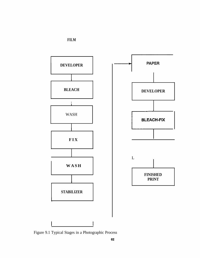
FILM
DEVELOPER
BLEACH
I
WASH
F I X
W A S H
STABILIZER
DEVELOPER
L
FINISHEDPRINT
Figure 9.1 Typical Stages in a Photographic Process
9.3 Waste Management
New regulations and tight restrictions make itincreasingly important to have good wastemanagement practices. Hazardous wastes needto be stored in designated collection zones andthese zones need to be closely monitored toprevent contamination of surrounding land ornearby waters.
Disposal
Disposal of photographic waste is not difficult.Usually, once the silver has been removed, theremaining chemicals can be disposed of in thesewer. Depending on the method of silverremoval employed, either metallic silver or asilver chloride sludge will be the final wastestream.
If the silver is not removed, the waste fixermust be disposed of as hazardous waste. Therinsewater and the prints are contaminated aswell as the fixer and any other fluid that comesin contact with these chemicals. The effluentfrom the shop in this case will be minimallyhazardous, but the volume could be large andit may be costly to have this material shippedout regardless of its low toxicity.
costs
It is not uncommon to see costs upwards ofone thousand dollars for disposal of a fifty-five gallon drum of hazardous waste. It usuallydoes not come as one fee, rather it is hiddenamong many small fees such as waste determi-nation, transportation, disposal site profile,acceptance into the disposal site, incineration,etc. This should be considered when the rawmaterials are being purchased, and it shouldhelp determine whether a waste minimizationprogram would be profitable.
6
9.4 Waste Reduction
The way to reduce hazardous waste from thephotography lab is to have a silver-removalmethod on-site. Once the silver has beenremoved from the effluent, most or all of it canbe disposed in the sewer.
Incentives
A significant incentive for waste reduction inthe photographic lab is the money that can besaved by removing silver from the effluent. Itis not so much the value of the silver itself, butthe reduced quantity of hazardous waste thatwill result from silver removal. The recoveredsilver may also contribute to the cost benefitsof the program, although the quantity and thequality of the silver recovered is usually low.
Methods
There are many different proven methods forwaste minimization in the photofinishingindustry. The main thrust of the programshould be toward silver recovery but there arealso other methods that should be employed inconjunction with that process.
A simple thing that should be done is to use asqueegee between photographic baths. Thiswill squeeze off the excess liquid to reducedrag-out to the next bath and contamination.Non-absorbent “twin-checks” can be used toidentify negatives. This will also reduce theamount of chemicals carried over to the nextbath.
Changes can be made in the initial purchasingfor the lab that can result in a reduced wastestream. To accomplish this, chemicals that areless hazardous should be used. For example, inthe photographic lab, chemicals that containheavy metals or trichloroethylene should beavoided.
3
It is also a good practice to utilize floating lidson the developer and bleach containers. Thiswill protect the chemicals from airborne parti-cles and from direct prolonged contact withthe air which can produce undesirable oxida-tion.
There is a waste reduction method calledcounter-current washing that effectively recy-cles the wash water. Clean water must be usedin the final rinse but the wash water in earlierstages is not required to be as pure. When thewater in the final rinse is no longer cleanenough to be used in that stage, it is still possi-ble to use it in the first film rinse. This canusually be done by changing a procedure andwill not require a capital expenditure.
Most developers and fixers can be recycled.This should be done and the proven process ofbleach regeneration should be used. Thebleach-fix can also be recycled on-site throughthe addition of specific chemicals.
S i l v e r R e c o v e r y
Silver recovery is achieved primarily throughtwo methods: metallic replacement and elec-troplating. Other methods exist but they aremuch less popular due to high capital invest-ment and because they require constant atten-tion from workers with high technical exper-tise.
Electroplating works in the following way:The fluid is passed through a channel with twocharged electrodes. A controlled DC currentflows between the electrodes and the silverplates-out on the negative or cathode side. Thesilver is then periodically chipped off the cath-ode and can be sold to create extra revenue.This method is popular because the silver pro-duced is in an almost pure form.
Disadvantages are the relatively high capitalinvestment, the difficulty of producing an
64
effluent with very low silver content, and theconstant need to adjust the current. Currentmust be closely monitored because an improp-er amperage will cause the formation of silversulfide according to the following equation:
This sulfide can coat the electrodes and makethe plating less effective or lower the qualityof the silver produced. Despite these minorgrievances, electroplating remains one of themost popular methods of silver removal.
The other predominant method of silver recov-ery is metallic replacement. In this technique,the silver solution is passed through a car-tridge which is filled with steel wool. Themore active metal (iron) reacts with the silverthiosulfate and goes into solution. The lessactive metal (silver) settles out as a solid. Thereaction proceeds according to the followingequation:
This method is popular because of the low cap-ital investment and because the silver contentin the effluent is reduced to very low levels.6
The disadvantage is the fact that spent car-tridges cannot be reused, rather they must beconstantly replaced at thirty to sixty dollarseach. Also, the recovered silver is in the formof a sludge and requires further processing.Furthermore, the effluent from the cartridgesis usually high in iron and may be unaccept-able to some sewer codes.
9.5 Summary
Waste minimization is a goal set by all indus-tries for ecological and other reasons. Wasteminimization in the photographic lab is espe-cially desirable because it is relatively easy todo and substantial amounts of money can be
saved. The following is a summary of the stepsthat should be taken in a waste minimizationprogram for a photographic laboratory:
1.
2.
3.
4.
Take accurate measurements of the quan-tities of products coming into the lab andof the effluent going out.
Examine the possibility of utilizing meth-ods of waste reduction that do not requirelarge capital investment such as usingsqueegees, counter-current washes, in-process recycling, floating lids, or lesshazardous chemicals.
Decide on the method of silver recoverythat best suits your needs depending onthe amount of effluent produced and localsewer code requirements.
Do an economic analysis to determine thecost of the recovery unit as well as theupkeep. Then determine the amount ofmoney that will be saved by putting thisunit on line. Calculate the payback period,if there is one, and if cost effective, imple-ment the system.
65
10. LUBRICANTS AND USED OIL AT SHIPYARDS
10.1 Introduction
Used oil and lubricants present a complicatedproblem from a regulatory standpoint. Oilproducts represent a valuable non-renewableresource and should be recycled when possi-ble. Used oil frequently contains contaminantsthat can pose substantial environmental andhealth risks if managed improperly. Regulatingused oil presents some special problems.Simply defining all used oil as the same mater-ial is difficult because oil is used for so manydifferent applications and varies widely inchemical composition. Each applicationdemands a different additive ingredient, andintroduces different contaminates through itsuse. Approximately 1.2 billion gallons of usedoil are generated each year by hundreds ofthousands of generators. Approximately two-thirds is recycled, primarily for use as fuel.The abuse of the used oil management systemas a dumping ground for hazardous waste isanother factor that has highlighted the need forregulations of used oil and lubricants.
Stututes
Congress recognized the need to address thisproblem, and in 1930 and 1984 enacted legis-lation amending the Resource Conservationand Recovery Act (RCRA) that establishesspecific goals and provisions for regulatingused oil. The Used Oil Recycling Act (UORA)of 1980 mandated the EPA to promulgate reg-ulations establishing standards to protect thepublic health and environment from the risksposed by improper management of used oil.
The Hazardous and Solid Waste Amendmentof 1984 (HSWA) established additional man-dates and provided additional constraints onthe regulations of recycled used oil consistentwith Congress earlier stated goals. Theseamendments established a special provisionwithin Subtitle C (Hazardous Waste
6
Management) of RCRA that authorizes EPA todevelop a separate regulatory framework forrecycled used oil, regardless of whether it islisted or identified as a hazardous waste.
Regulations
In response to these mandates and constraints,the EPA has conducted a number of studies,has promulgated regulations to restrict burningused oil, and is developing other regulations tobring used oil under broader regulation con-trol.
The existing regulation (40 CFR part 266,Subpart E) was promulgated on November 29,1985 (50 FR 49164), and contains administra-tive requirements and restrictions on used oilthat is burned for energy recovery. Used oilthat is not used for energy recovery is current-ly not regulated unless it has been mixed witha listed hazardous waste.
The rule establishes a used oil fuel specifica-tion consisting of six parameters includingfour toxic metals, flashpoint, and total halo-gens. Used oil fuel that meets the specificationis conditionally exempt from regulations,while off-spec used oil is subject to certainrestrictions and requirements. The require-ments include recordkeeping and use ofinvoice, notification, and require notices.Under the rule, “off-spec” used oil can only beburned in devices such as industrial boilersand industrial furnaces. A new regulationpassed concerning the burning of hazardouswaste in industrial boilers and industrial fur-naces (EPA’s BIF Regulations).
Mixtures of used oil and listed hazardouswastes are subject to more stringent hazardouswaste management regulations. The used oilfuel rules (40 CFR part 266 Subpart E) estab-lish a rebuttable presumption as a means fordetermining when mixing used oil and haz-
6
ardous waste has occurred. Under this provi-sion, used oil containing greater than 1000ppm of total halogens is presumed to havebeen mixed with hazardous waste. The pre-sumption can be rebutted by showing that thesource of the halogens is not a listed halo-genated solvent.
In November 1985 EPA published two propos-als that would bring used oil under broaderregulatory control. Both of these proposalsgenerated a great deal of concern within theregulated community. The major concern wasthat the listing would increase cost and createa stigma associated with the listing such that itwould disrupt the used oil management systemand be environmentally counterproductive tocurrent recycling efforts.
On November 19, 1986 (51 FR 41900) theEPA published a final determination not to listused oil bound for recycling as a hazardouswaste under RCRA, and set out a strategy todecide how to control used oil bound for dis-posal. The proposed management standard andcertain other initiatives were deferred pendingthe outcome of the decisions on disposal con-trols.
On October 7, 1988, the Court of Appeals ofthe District of Columbia found that the EPAacted contrary to law in its determination notto list used oil under RCRA section 3001based on the stigmatic effects. The court ruledthat the EPA must determine whether to listany used oil based on the technical criteriaspecified in the statute.
Currently the EPA is reviewing new data dueto the “unrepresentativeness” of the 1985 dataand the age of the data. Finally, the promulga-tion of the toxicity characteristic (TCLP) (55FR 117978, March 29, 1990), is known toidentify certain used oils as hazardous andthese findings will be reviewed with currentcollection of data. On September 23, 1991, a
67
notice of proposed rule making was issued onthe identification and listing of used oil as ahazardous waste. EPA will use the commentsand data collected to make a final decision tolist some or all used oil as hazardous waste, asproposed in November 1985.
10.2 Description of Process Operations ThatUse Lubricants
There are hundreds of different types of oilused for a wide variety of purposes in the ship-yard and on ships. Some, such as engine lubeoils, are formulated to satisfy a wide range ofengine types and uses. Other oils may be for-mulated for special applications where eachoperating department requires a special addi-tive or specific properties to suit their needs.
A brief description of some of the major typesof oils follows.
Fuels Fuels can become used oils if they arecontaminated and cannot be used for theiroriginal purpose. Fuels are also the most com-mon means for disposal of used oils. Twomajor types of fuel are used at a shipyard, dis-tillates and residuals. As implied, distillatesare products which are distilled to producespecific boiling ranges for various enginessuch as gasoline, diesel and clean burningfuels (boilers). Residual fuels (# 4, 5, 6bunker, etc.) may be mixtures of distilled andundistilled petroleum fractions blended tomeet specific flash points, viscosity, sulfur,BTU, and other properties.
Erwine Lubricants Gasoline engine lubes maycontain from 10% to 30% additives and maybe made from paraffinic and/or naphthenicpetroleum oils. Synthetic oils are also used.Truck lubes require somewhat higher deter-.gency than passenger cars and a high viscosityindex (VI) to ensure good cold-starting charac-teristics.
Diesel engine lubes require a relatively highlevel of detergency to minimize the effects ofsoot formation in the combustion chamber. Inaddition, high compression ratio of dieselengines creates very high piston ring zonetemperatures. This requires lubricants withgood oxidation stability (paraffinic-basestock). Diesel lubes use high alkaline deter-gent additives to neutralize some of the effectsof high sulfur dieseI fuels.
Hvdraulic Fluids Petroleum-based materialsare used for many applications. These materi-als are similar to lube oils but generally con-tain a lower percentage of additives.
Synthetic Fluids These fluids are employedwhere fire resistance is required. These fluidsconsist of phosphate esters, polyglycols, poly-olifins j silicones, silicate esters, and halogenat-ed hydrocarbons such as chlorofluorocarbonpolymers, fluoroesters, and blends of thesecompounds.
Transmission Oils Petroleum based oils aregenerally used for these applications with spe-cial additives to provide shear resistance.Some synthetic oils are also used.
Cutting and Cooling Oils These oils may bepetroleum or synthetic oil formulations. Thelatter are used where fire resistance and highstability are required. Additives are used toimpart special properties such as shear or highpressure resistance. Emulsifiers may also beincluded to enable use as a 1% to 2% wateremulsion or to provide the ability to wash offthe oil after a cutting operation.
Bilge and Ballast Oils Ships generate largevolumes of oil/water mixtures either frombilge or ballast tanks. These oils vary consid-erably depending upon the fuels used and theoil transported. While the concentration of theoil in water may be only a few ppm to 2% byvolume, the quantities generated are often so
68
large that the separated oils can amount to sig-nificant volumes.
Building-Ways Lubricants Building-waysgenerate large volumes of launching greases(basecoat and slipcoat) that are used forlaunching or moving ships on sliding ways.The base coat is a paraffin wax and the slip-coat is usually a calcium base petroleumgrease.
10.3 Source Reduction or Minimization
One of the first objectives of any oil manage-ment program is the minimization of the vol-umes of used oil generated. Also included inthis category of management is the minimiza-tion of contaminates, which reduce the valueof oil for recycling purposes. Listed below areways to accomplish minimization.
Extending the Useful Life of the Oil
Following is a list of ways to accomplish thisobjective, along with some related concerns.
Increase the Period Between Oil Changes Ineffect, this would allow the oil to get dirtierbetween changes. This may be acceptableunder certain instances, but could jeopardizeengine warranties, wear, or performance char-acteristics. Some automotive engines have runover 50,000 miles between oil changes, butthis is not recommended for the average user.Large shipyard users can justify oil qualitytesting to maximize use times.
Use a Better Oil A higher quality oil mayprove cost-effective. Synthetic lube oils havebetter wear properties but many engine war-ranties may be voided if the lubricant is notchanged on a specific schedule, thus negatingthe advances of synthetic lubes in some cases.
Check Seals and Gaskets Reduce contamina-tion by checking seals and gaskets frequently
to minimize contamination.
Control Operating Conditions Control isrequired to avoid excessive temperatures thattend to degrade oil. Operating at extreme loadscan have the same deleterious effect.
Segregation
Segregation is the key to a successful reclama-tion and cost reduction program. The mostcommon types of contaminants that are ofteneasy to eliminate are noted below.
Low Flash Point Gasoline, carburetor cleaner,paint thinner, and other volatile materials,when mixed with used oils, create severalproblems in reclamation and/or disposal.
Chlorinated or Freon Solvent Mixing thesematerials with unused oils should be avoidedsince they severely reduce the potential forreclamation.
Synthetic Oil and Fluids It is often profitableto segregate these materials from used oilsince the synthetic materials can be reclaimedseparately. Currently, synthetics can be used asplasticizers if contamination does not exceedabout 2% to 5%.
Waste Exchange
Waste exchange or downgrading are the sameactivities. Generally, waste exchange is down-grading to an off-site facility, whereas down-grading is an on-site activity. Some states,areas, and industries have extensive wasteexchange operations. This can be very benefi-cial. An example is the use of a high purity oilafter drainage for another less critical applica-tion. A common use is to emulsify and use theoil as a cutting or cooling oil. Some used lubescould also be used as quench oils.
69
On-Site Contracted Services
There are a number of companies that providemobile units for all treatments. For example,certain lube oils are commonly reclaimed bytreatment to remove volatile hydrocarbons,water, and accumulated solids. Equipment toaccomplish this can be provided by outsidecontractors who service on-site units.
Cutting and cooling oils can also be reclaimedby similar services. These emulsified oils candegrade biologically and emit objectionableodors. Also, oils may accumulate or separateout (tramp oils) which need to be removed orreemulsified. Contracted services can provideequipment and manpower to reclaim such oils.
10.4 On-Site Recycling and ResourceRecovery
On-site treatment for reclamation of oil shouldbe limited to physical processing such as cen-trifugation, coalescence, distillation-evapora-tion, stream stripping, and graving settling. Adescription of the most common unit opera-tions and their application to on-site reclama-tion is briefly discussed below. A completesystem for oil reclamation may contain one ormore of the following unit operations.
The Control Technology for Removal of Oiland Grease
The control technology for oil and greaseremoval varies in complexity and the basicprocesses are involved in the collection andrecovery of the oil and removal of the desiredpollutants before discharge to the receivingsystem (receiving waters or POTW). Thetreatment of the waste water to remove pollu-tants other than oil and grease will not be cov-ered in this section.
Oil and grease contained in the waste waterfrom shipyard operations or in bilge and bal-last systems on ships can be removed by theuse of widely accepted techniques. Since theremoval of the oil and grease depends on thecondition of the oil-water mixture, the type ofequipment must be carefully selected. Thetype of oil-water mixture may be classified asoil and grease present as free oil, dispersed oil,emulsified oil, or dissolved oil. Free oil is usu-ally characterized by an oil-water mixture withdroplets greater than or equal to 150 micronsin size while a dispersed oil mixture has adroplet size range between 20 and 150microns, and an emulsified oil mixture willhave a droplet size smaller than 20 microns. Awastewater with an oil-water mixture wherethe oil is said to be soluble is a liquid whereoil is not present in the form of droplets ( oilparticle size would be less than 5 microns).Soluble oils can be selectively extracted byvarying degrees by solvents if extraction isneeded.
Centrifugal Separators Centrifrigal separatorscan be used to separate solids from used oilswhen settling rates need to be enhanced andgravity separation requires a long residencetime or when space limitations require smallvolume equipment. Disadvantages of this typeof separation are large power requirements andin effectiveness when solids are trapped inemulsions.
The most common type is the mechanical cen-trifuge. The simplest mechanical centrifuge isthe tubular design which is a high speed smalldiameter bowl. Normally it is fed at one endwith separated liquid removed at the other endthrough effluent take-offs at different radii.The machine capacity is limited to about 20gallons per minute.
The most common type today is a disk-typecentrifuge which is often operated to generateforces up to 9,000 times that of gravity. Figure
7
3 gives an example of a vertical bowl withfeed entering from the top axis. The inclineddisks aid in the separation by a mechanismsimilar to plate settlers. The oil o light liquidmoves to the top of the disks and travels to thecenter of the bowl. The water or heavy liquidand any solids moves to the outer wall of thebowl. Capacities of disk machines range from5 to 500 gallons per minute. The specific grav-ity differences should be greater than 0.01 anddroplet sizes greater than 1 micron.
Coalescers This treatment provides a largesurface area media that attract one phase of anemuIsion (e.g., water) and repel the oil phase.For media and water removal, emulsion ofused oil is pumped through the media andwater droplets attracted to the surface coalesceand are separated and removed. Often, filtra-tion and coalescence are accomplished togeth-er in a combined unit called a filter-coalescer.Such units are commonly used to removesolids and water from fuel oils and other distil-late fuels. Coalesces can remove water fromoil down to levels of 5-10 ppm oil dependingon the quality of input and system design.
The most common coalesces pass the phasesthrough some type of solid bed, fiber mesh,metal screen, or membrane. The actual mecha-nism for coalesces using a solid surface is notwell understood. A mesh or cartridge of fiberis the most common type. Polypropylene,nylon or polytetrafluorocarbon fibers are com-mon for oil and water separation. Glass andglass treated fibers can be used. The fiber sizeor media pore size decreases with the need tohandle smaller droplet sizes. Various singlematerial coalesces are available. A big use forcoalesces application is the removal of lowconcentration of droplets less than 20 micronsin diameter as a polishing unit after other sepa-ration techniques are being used. Coalesceshave their problems. The pore size in the ele-ments are small and the stream needs to befree of solids. Most vendors recommend a pre-
0
filter to remove solids. Even then, especiallywith emulsions, finely divided solids areremoved in the coalescing elements andrequire a periodic backflushing or replacementof elements. For situations where solids are aproblem, a packed bed similar to a deep bedfilter can be used with a periodic backflush.
Filters A wide range of filters are available toseparate solids from used oil streams. Thenature of the filter media and design of theunit will depend on the particle size and con-centration of the solids to be removed. Typicalfilter media include sand, clay, and fibrousmaterial which can be also selected to coalesceand remove water.
Gravity Separators The primary function ofan oil and water separator is to separate freeoil from wastewater. Such gravity separatorswill not separate oil droplets smaller than thesize of the free oil nor will it break down theemulsion. The three main forces which act ona discrete oil droplet are buoyancy, drag, andgravity. The buoyancy of the oil droplet is pro-portional to its volume and the drag is propor-tional to the area of the droplet. As the diame-ter of the oil droplet decreases, the ratio of itsvolume to the surface area also decreases.Because of the droplet size relationship, largerdroplets tend to rise while smaller dropletstend to remain suspended. With particle diam-eters greater than 150 microns, the rate of rise(ft/min) of oil droplets in waste water maybeexpressed as:
Vt= 0.0241 (Sw - So/u)
where
Vt = rate of rise of oil droplet in waste-water (ft/min)
Sw = specific gravity of wastewater atdesign temperature of flow
7
So = specific gravity of oil in wastewaterat design temperature flow
u = absolute viscosity of the oil in wastewater at design temperature, in poises
An API Separator is based upon the concept ofthe rising oil droplet as expressed above and isbased on the following four relationships.
Ah= F(Qm/Vt)
Ac = Qm/Vh
d/B = 0.3
L= F (Vh/Vt)d
where
Ah= minimum horizontal area, in sq ft
F = design factor for turbulence andshort-circuiting factor
Qm = wastewater flow, in cubic feet permin
Ac = minimum vertical cross-sectionalarea in sq ft
Vh = horizontal flow velocity,not to exceed 15 Vt or 3 ft/min
d = depth of wastewater
in ft/min,
B = width of separator chamber, in ft
L = length of separator chamber, in ft
When a free oil or dispersed oily water mix-ture is brought to a quiet state within a sufil-cient amount of time, the oil droplets will coa-lesce and separate from the waste water formi-ng a floating oil layer which can be separatedfrom the wastewater by skimming off. Figure
1
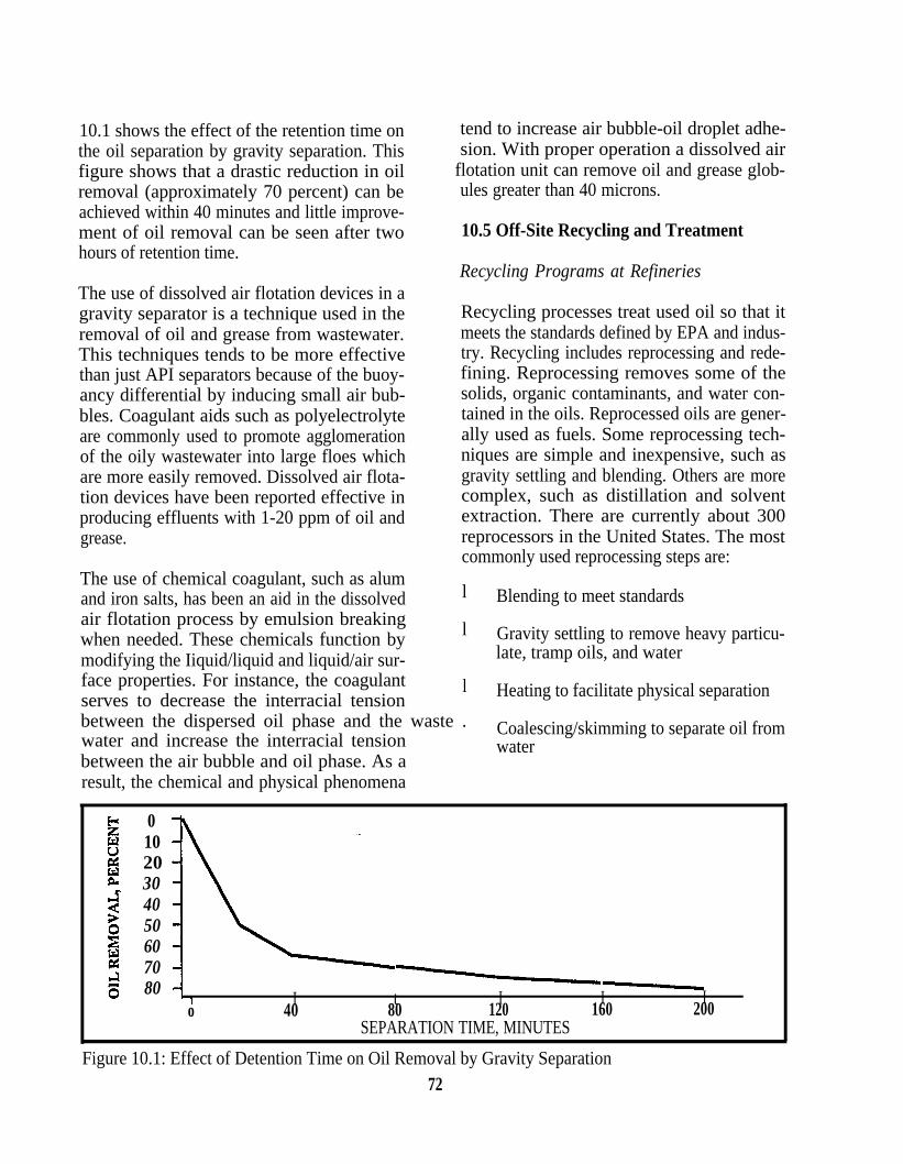
10.1 shows the effect of the retention time onthe oil separation by gravity separation. Thisfigure shows that a drastic reduction in oilremoval (approximately 70 percent) can beachieved within 40 minutes and little improve-ment of oil removal can be seen after twohours of retention time.
The use of dissolved air flotation devices in agravity separator is a technique used in theremoval of oil and grease from wastewater.This techniques tends to be more effectivethan just API separators because of the buoy-ancy differential by inducing small air bub-bles. Coagulant aids such as polyelectrolyteare commonly used to promote agglomerationof the oily wastewater into large floes whichare more easily removed. Dissolved air flota-tion devices have been reported effective inproducing effluents with 1-20 ppm of oil andgrease.
The use of chemical coagulant, such as alumand iron salts, has been an aid in the dissolvedair flotation process by emulsion breakingwhen needed. These chemicals function bymodifying the Iiquid/liquid and liquid/air sur-face properties. For instance, the coagulantserves to decrease the interracial tensionbetween the dispersed oil phase and the wastewater and increase the interracial tensionbetween the air bubble and oil phase. As aresult, the chemical and physical phenomena
01020304050607080 I t
o 40 80SEPARATION
Figure 10.1: Effect of Detention Time on Oil Remova72
tend to increase air bubble-oil droplet adhe-sion. With proper operation a dissolved air
flotation unit can remove oil and grease glob-ules greater than 40 microns.
10.5 Off-Site Recycling and Treatment
Recycling Programs at Refineries
Recycling processes treat used oil so that itmeets the standards defined by EPA and indus-try. Recycling includes reprocessing and rede-fining. Reprocessing removes some of thesolids, organic contaminants, and water con-tained in the oils. Reprocessed oils are gener-ally used as fuels. Some reprocessing tech-niques are simple and inexpensive, such asgravity settling and blending. Others are morecomplex, such as distillation and solventextraction. There are currently about 300reprocessors in the United States. The mostcommonly used reprocessing steps are:
l Blending to meet standards
l Gravity settling to remove heavy particu-late, tramp oils, and water
l Heating to facilitate physical separation
. Coalescing/skimming to separate oil fromwater
I I I120 160 200
TIME, MINUTES
l by Gravity Separation
● Solvent extraction to remove ketones,alcohols, and hydrocarbons
● Distillation to remove water and light fuel.
A number of other types of unit operations areused to a lesser extent, including magneticseparation, centrifugation, hydrocyclone sepa-ration, ultrafiltration, and carbon adsorption.Techniques are chosen based on their cost,efficiency, capacity, and residue production.Reprocessing often produces residues thatrequire disposal. Reprocessing is generallyapplicable to streams that are not highly conta-minated by metals or hazardous organic com-pounds. Reprocessing techniques are relativelysimple and inexpensive to operate. Howeverthey have difficulty in removing metals andadditives.
Redefining involves a full scale treatment ofused oil to produce lube oils of equivalentquality to virgin oils. In the 1960s there wereabout 150 rerefineries in the United States.Today there are only about 15 rerefineries dueto stricter regulations and low oil prices. Thegeneral approach is to:
● Remove water by atmospheric distillation
● Remove volatile organic and solvent byatmospheric distillation
● Remove additives and sludge by chemi-cal treatment, extraction, vacuum distilla-tion, or membrane processes
● Remove metals and chlorides by chemicaltreatment, clay treatment, or extraction
● Fractionate by vacuum distillation
● Perform final finishing by hydrotreatmentclay treatment, or vacuum distillation.
Processes that generate by-products such as
7
the acid-clay process, are declining in popular-ity due to by-product disposal problems.Rerefineries can handle almost all oil wastes,although processing is easier for relativelyuncontaminated streams. Products includelight ends, which are burned as fuels, lube oil,and asphalt flux. The asphalt flux contains theheavy bottoms, which include the metals andsludge. Redefining reutilizes used oils for itsoriginal purpose and produces little or nowaste by-products. However it require a sig-nificant capital investment and has high oper-ating cost.
Fuels Programs and Thermal Treatment
The second type of treatment category consistsof a process designed to reduce the volume ofoil waste and the hazards it presents. Thermaltechniques are used for waste disposal andenergy recovery. Used oils are similar in quali-ty to No. 6 fuel oil and have a relative highBTU content. This makes them well suited toburning in furnaces and boilers. Before bur-ning, the oil must be processed to meet environ-mental regulation specifications. Air emissionsare also regulated. Since used oil has a highheat content and usually requires minimal pro-cessing to meet standards, combustion forenergy recovery is often the most cost effec-tive way to manage used oil. Most reproces-sors use recycled oil as a fuel source on ships,cement kilns, furnaces, and external combus-tion boilers.
Oxidation and Biological Treatment
Oxidation techniques can also be used fordestruction of used oil waste. These tech-niques use high temperature and pressure todecompose organic compounds and convertmetals into easily managed salts. This tech-nique has been gaining in popularity in recentyears.
3
Biological processes breakdown hydrocar-bons in oil waste. They are commonly used forpretreatment of oily wastewater, and for wastein which excessive contamination and low oilcontent makes recovery infeasible.Microorganisms that decompose oil waste areubiquitous. The two types of biological sys-tems are:
● Solid based system, including landfarm-ing and attached/entrained growth sys-tems
● Liquid based system, including biologicalreactors and lagoons.
A number of innovative biological processeshave emerged in recent years. Biological acti-vated carbon treatment (BACT) is one suchprocess. Bioaugmentation is another process inwhich microorganisms specifically suited todecompose a particular waste are added to thesystem. Virtually all oil wastes are suitable forbiological treatment, although high levels ofmetals or other toxic substances can inhibitefficiency. The efficiency depends on the treat-ment system, oil content, and contaminantconcentration. Biological process effectivelyreduces the volume and hazards of oil waste,and has low capital and operating costs.However they are slow, require a lot of space,and do not reutilize oil. In addition, they pro-duce a sludge requiring disposal and someprocesses such as landfarming, have a highrisk of environmental contamination.
10.6 Factors in Selecting a TreatmentOption
The main factors to consider in selecting atreatment option are regulatory compliance,economics, environmental acceptability, andtechnological capabilities. Each of these fac-tors should be considered before a treatmentoption is selected.
74
Treatment must comply with all regulations.Unless used oil is shown to meet specific stan-dards, it must be managed as a hazardouswaste in some states. Thus proper manifestsand permits must be obtained for all trans-portation and treatment. Generators maintainliability for oil waste until it is destroyed orrecycled. Thus by destroying or recycling thewaste, proper treatment can ensure that gener-ators manage oil waste legally and can relievethem of liability.
The treatment system must be cost effective. Atreatment system should be selected that maxi-mizes oil waste recycling values and mini-mizes disposal costs of waste and waste treat-ment by-products. Economic factors includecurrent market oil prices, capital and operatingcost permitting, insurance costs, transportationcosts, and treatment product values.
The treatment system must be environmentallyacceptable. The treatment system should mini-mize exposure of employees to hazardouswaste, generate little or no waste by-products,and not emit air, land, or water contaminates.Oil waste often contains heavy metals andhazardous organic compounds. Shipyards haveboth the legal and ethical responsibility toensure that these compounds do not contami-nate the environment.
The treatment system must be technologicallyfeasible. The system must produce oil ofrequired purity and composition. It must alsohave enough capacity to handle the flow ofwaste to be processed. In addition, the treat-ment system should be within the technicalcapabilities of the company operating it.Employees must have training and experienceneeded to operate, maintain, and repair thephysical and chemical processing equipment.
11. FIBERGLASS REINFORCED CONSTRUCTION OPERATIONS
11.1 Introduction
Many shipyards and boatyards are involved inthe use of fiberglass-reinforced compositeplastic for production of hulls and other ship-building material. This process involves thecombination of resin and reinforcing material.The combination is a product which has anexcellent strength to weight ratio. The resin isa polymer and the reinforcing material is fiber-glass. The resin and fiberglass is sprayed ontoa mold which is shaped in the definition of ahull or other type of structure. The structure isusually lighter than metal or wood structuresand may be stronger. The waste is generatedfrom the fiberglass construction and includessolidified resin, contaminated solvent fromclean-up, scrap fiber, and resin waste stream.
11.2 Recreational and CommercialShipbuilding Manufacturing
Thermoplastic and thermoset reinforced plas-tic are used in many products used in thedevelopment of Commercial and naval ves-sels.
Raw Materials
The material used in the construction of fiber-glass reinforced plastic include fiberglass, sol-vents, catalysts, and other chemical additives.
Resins
The resin is usually supplied dissolved in anorganic solvent. The solvent acts as a carrier toheIp processing and to dissipate heat generatedin the exothermic crosslinking reaction whichoccurs with the catalyst. The classes of resinsused include polyesters, epoxies, polyamides,and phenolics compounds. The classes refer tothe functional group which is attached to themonomer and are normally not a hazardousmaterial but the solvent in which the resin isdissolved may be hazardous.
75
Waste resin used in shipbuilding constructionis determined to be hazardous if the resin con-tains any residual solvent. If the waste con-tains a residual solvent and the solvent is listedas an F series solvent it is a hazardous waste.If the solvent is not listed additional testingmay be required before a solvent is determinedto be non-hazardous.
Fiberglass Substrate
Fiberglass is manufactured in several differentforms. This gives several variables in strength,cost, and compatibilities with resin systems.The fiberglass content ranges from 10 to 50percent. The forms include continuous-strandfiber, chipped fiber, and milled fiber.
catalysts
With epoxy resins,catalyst to develop
curing is done by using adesired properties. Agents
include amines, anhydrides, aIdehyde conden-sation products, and Lewis acid catalysts.Amines such as diethylenetriamine and trieth-ylenetetramone are often used for room tem-perature curings. Some of these chemicalsmay be classified as non-hazardous and the generator is responsible forthe determination The generator must keep up-to-date information on all hazardous wasteclassification.
Additives
Chemical additives may be added to obtaincertain property characteristics. These productcharacteristics include resistance to heat agingand processibility. The additives include moldreIease agents, foilers, Iow-shrink, low profileadditives, tougheners, thickening agents, col-orants, forming agents, lubricants, plasticizers,and free radical initiators. There are four class-es of additives which are used in plastics andinciude fiIlers, plasticizers, reinforcements,and colorants. These additives account for
90% of additives used in plastics. Compared toresins, these materials are generally chemical-ly inert. The hazardous waste classification foradditives should be reviewed to determine ifthese materials are hazardous.
Solvents
Solvents are used in large quanties for dilutingthe resin mix and for equipment clean-up.Acetone. MEK (methyl ethyl ketone) andmethanol are most often used. These are listedhazardous materials.
Process Description
The manufacture of fiberglass ships and boatsinvolve a number of process steps which aredescribed below:
l Mold Preparation
l Resin Preparation
l Gelcoat Application
l Fiberglass Application.
Mold Preparation
Molds are used to give structure and support tothe shape of the structure being built such asthe hull of a ship or boat. Most molds aremade of wood with a plastic finish.
Resin Preparation
Most resins are pre-promoted resin. The resinis in 55 gallon drums and is pumped from astorage into a spray gun. The solvent and cat-alyst are added through a separate feed line.
Gelcoat Application
The gelcoat is a pigment resin or a polyesterresin based paint with a styrene content of
76
approximately 30 percent. The application iswith either an air atomizer or airless spraygun. This application is usually conducted in aspray booth. The catalyst can be added byhand mixing or by a plural component systemwhich is injected through a separate line intothe gun where it mixes with the resin. Oncereacted the polyester resin begins to thermoset.Once cured, the resin cannot be softened orreshaped by heat. The polyester resin lay-upoperation results in the use of solvent. Acetoneand methylene chlorine are often used in thisoperation. These solvents are used to preventclogging and to clean the operator’s handsduring clean up.
Fiberglass Application
For fiberglass operations, the resin is ethermixed, sprayed or brushed onto the surface ofthe fiberglass material. The fiberglass materialcomes in a woven mat or cord-like rovingwhich is applied with the resin during fabrica-tion.
Wrote Generatwn
The generation of hazardous waste in the man-ufacture of fiberglass and composite plasticmaterial is very common. These hazardouswaste by-products are in the form of chemical-contamined reagent, additives, solvents,wastewater, and hydraulic fluids. The quanti-ties vary from a few gallons to several tonsdepending upon the size of the operation.
Liquid Waste Generation
Liquid hazardous waste includes:
l Cleaning solvent from equipment cleanup
l Resin leftover in tanks and other sources.
The solvent waste is contaminated with resinfrom the cleaning operation. The scrap resin is
from the waste which is leftover and cannot beused later.
Solid Waste Generation
The solid waste includes:
b
l
l
l
l
Gelcoat and resin overspray materialwhich does not land on the fiberglassmold surface.
Unused raw material resin that has exceed-ed the shelf life of the material.
Raw material containers which includefiberglass boxes, drums of gelcoat, andother containers.
Empty resin and solvent drums
Clean-up rags.
Volatile Waste Generation
An open container or drum which contains.solvent and generates fugitive emissions is avolatile waste generation. The fugitive airemissions are often generated during mixingand treatment during which the solvent fromthe coated fiberglass is driven off during thecuring operation. The use of ventilation andthermal oxidation is used to incinerate the sol-vent emissions. Some recovery systems useactivated carbon to recover the solvent emis-sions. The various techniques used mustundergo economical analysis to determine thebest technique to be used.
11.3 Source Reduction
Source reduction is used to reduce the amountof hazardous waste generated during the man-ufacturing operations. Many source reductionapproaches have low capital cost require-ments. some source reduction techniquesrequire only housekeeping changes to reduce
hazardous waste and yield significant cost sav-ings. Areas which have been identified assource reduction are the following:
l Material Application
l Thermal Plastic Resin
l Operation and Waste Management
l Inventory Control.
Waste reduction opportunities are discussedbelow.
Material Application
Major waste reduction is available by optimiz-ing material application processes. Theseprocesses include spray delivery systems andnon-spray resin application methods. The non-spray application includes close mold system,vacuum bag mold system, resin roller dis-penser prespray fiber reinforcing and in-houseresin impregnation. These non-spray tech-niques reduce material waste and energy costduring application. The lower application pres-sures reduce the cost and maintenance of pres-sure lines, pumps, controls, and fittings.Routine cleanup of work area is also reduced.
Spray Delivery Systems
Most shipbuilding mold fabrication of fiber-glass materials utilize resin spray applicationfor the transferring and application of coatingsand resin to the mold. Conventional gun-type resin application systems use compressedair, high fluid pressures, or combinations offluid pressure and compressed air to atomizeresin material. Catalyst for the resin systemsare normally introduced inside the spray appa-ratus or as the resin is atomized from the spraynozzle.
The fabrication process for fiberglass con-
77
struction and the waste which is produced ishighly dependent on the equipment and proce-dures used. The current system of resin andgelcoat delivery systems include high-pressureair, medium-pressure airless, and low-pressureair-assisted airless spray guns.
l The high-pressure air system is used lessdue to the large amount of expensivehigh-pressure compressed air requiredand the high air emission produced.
l The airless method produces a pressur-ized resin stream electrostatically atom-ized through a nozzle. The nozzle orificeand spray angle can be varied by usingdifferent tips. The size of the orificeaffects the delivery efficiency, with largerorifices resulting in greater raw materialloss. Airless spray guns are considered tobe very efficient in the delivery of resinto the work surface.
l The air-assisted airless technology modi-fies the airless gun by introducing pres-surized air on the outer edge of the resinstream as it exits the pressure nozzle. Theair stream forms an envelope whichfocuses the resin to follow a controllablespray pattern. Since more resin ends upon the mold with this technology, theamount of spraying is reduced leading toa reduction in air emissions. It is estimat-ed that a savings of 5 to 20 percent in netloss of resin spray waste for the air-assist-ed airless gun is achieved comparedthe airless gun.
Non-Spray Resin Application Methods
The standard practice for most open mol
to
dapplication. of fiberglass has been the use ofspray delivery of resins. The conventionalgun-type resin application systems are veryefficient in delivery of large quantities of resinto the work surface. The spray delivery sys-
78
tems are also advantageous when the productmold has many different surface shapes. Manynon-spray application techniques have beendeveloped but are normally messy to handleduring application. However, these techniquesshould be considered because they may beapplied at the shipyard in certain cases. Thenon-spray applications are as follows.
Prepreg Fiber Reinforcing
The use of prepregs which is reinforced fiberthat is presaturated with resin, offers a numberof advantages over conventional spray tech-niques. The prepregs are normally formulatedwith epoxy-based resins which require placingthe mold in an oven or autoclave to completethe curing cycle. The disadvantages of thistechnique are that the material requires refrig-eration for storage and material costs are high-er. These techniques are best suited for appli-cation requiring high strength to weight ratio.
Resin Roller Application
This application uses pumped resin and catalystfrom drums or bulk containers. The resin andcatalyst are precisely metered in a gun-type linemuch like the paint plural component systems.A resin roller dispenser transfer the catalyzedresin to the mold surface while reducing materi-al lost due to overspray and bounceback of theresin. Air emissions are greatly reduced withthis type of delivery system.
Thermoplastic Resins
Thermoplastic resin can be easily rescued bythe application of heat which returns the resinto a liquid state. The resin can then be reusedin the manufacture of fiberglass components inshipbuilding. The used of thermoplastics offerfaster curing cycles, lower emission duringprocessing, lower costs per pound of rawmaterial used, ease of recycling material, andin some cases, lower labor costs. With the
recent advances in the processing technologiesand thermoplastic resin systems the shipbuild-ing industries are reexamine in the applicationof thermoplastics versus therosets materialsystems.
Operation and Wrote Management
By improving operating efficiency and wastemanagement practices, significant sourcereduction opportunities can be achieved.Listed below are operating practices and wastereduction methods.
1. Change spray orientation in the spraymold to reduce overspray and bounce-back wastes.
2. Reduce and recycle solvent usage forclean up application.
3. Segregate waste to improve recyclabilityand reduce treatment of various wastestreams.
11.4 Recycling and Resource Recovery
Recycling and resource recovery includesdirect use of waste as a raw material for anoth-er process or product. It requires recovery ofthe valuable material from the waste stream.This helps reduce the hazardous waste genera-tion in many instances.
Solvent Used and Waste Management
Solvents play a major role in the application offiberglass operations. Solvents such as ace-tone, methylene chloride, methanol,methylethylketone, toluene, and xylene arecommonly used in this type of operation. Thesolvents are used to clean-up equipment andadjust the specific gravity of the resin beforeuse.
Acetone and other solvents are used for gener-al cleanup applications. The solvents are used
to remove uncured resins from spray equip-ment, rollers, brushes, tools, and furnished sur-faces.
Disposal of contaminated solvent has becomea major cost in the operational expense area.In addition RCRA imposes long term liabilityfor these wastes which must be addressed inthe disposal consideration. Currently majorresearch and engineering studies are occurringto find alternative solvents and techniques toreduce air emissions due to reportion requiredunder the EPRCA regulations.
Considerable effort should be placed on therecovery of solvents to reduce the disposalcosts and save on material cost due to recy-cling. Due to the current air emission regula-tion and pollution prevention requirement,alternative solvent management systems suchas solvent substitution, onsite recycling, off-site recycling, and alternative fuels incinera-tion should be considered.
On-Site Solvent Recovery
Distillation can provide a cost efficient solventwaste management. The solvents produced arereused for cleanup application. This reusereduces the purchase of new solvents. Theapplication of solvent reuse is discussed in thechapter on solvent recycling.
11.5 Treatment
Incineration
Incineration is a waste management option forcontaminated solvents, resins, contaminatedcleanup rags and off-spec materials producedduring production. Incineration of these wastesprovide an economical heat recovery due tohigh BTU content and low halogen content.Transportation is a negative in the off-sitefacilities because they must be hauled by alicensed waste hauler. Again the RCRA regu-
79
lation places the liability issue on the genera-tor as well as the transporter.
Due to the land disposal phaseout and restric-tive use of landfill sites, the demand of incin-eration services has grown rapidly in theUnited States and Canada. At the same time,new incineration capacity is slow due toNIMBY opposition and regulatory require-ments from federal, state, and local regulatoryagencies. Restrictive use of landfills willincrease the costs for these services and thecompetition among generators for access willbe great. Thus generators should avoid thisdeveloping trend by seeking alternative meth-ods versus incineration.
80
12. WASTE MINIMIZATION AND EDUCATION
12.1 Introduction
Waste minimization is a constantly changingfield with many innovations in the waste mini-mization field. To keep abreast of these newchanges, shipyards must use the variousresources that are available to them to stayabreast of these changes. The following sec-tions give options to shipyard personnel to keepabreast of this field to make the needed changesto reduce the hazardous waste generated at theshipyard.
12.2 Pollution Prevention InformationSources
The Pollution Prevention InformationClearinghouse (PPIC)
EPA established the PPIC in 1988 to promotesource reduction and recycling through infor-mation exchange and technology transfer. ThePPIC is a free clearing house service containingtechnical, policy, programmatic, and legislativeinformation relating to pollution prevention andrecycling. The clearinghouse is available to thepubic at no charge.
The PPIC is comprised of the followingexchange systems.
RePosito rv. A hard copy reference library con-taining the most current pollution preventionand recycling literature. The repository includescase studies, fact sheets, training materialsvideotapes, and general references.
Pollution Prevention Information ExchangeSystem (PIES) A free, 24 hour electronic net-work accessible by personal computer equippedwith a modem. The PIES consist of messagecenter, bulletins, down-loading files, technicaldata bases, and conference listings.
8
Hotline. Telephone services to answer or referquestions and to provide links to the PIES forusers without access to a personal computer.
Outreach Effort. Workshops, training, andindustry-specific pollution prevention materialsare developed for designed user groups.
To obtain additional information on the PPICand PIES write to:
U.S. Environmental Protection AgencyOffice of Environmental Engineering andTechnology DemonstrationPollution Prevention InformationClearinghouse401 M Street, S.W. (RD-681)Washington, D.C. 20460Tel: 202-260-3161Fax: 202-260-4524
12.3 State Waste Minimization Programs
Alaska:
Alaska Health Project Waste ReductionAssistance Program431 West Seventh AvenueAnchorage, AK 99501(907) 276-2864
California:
California Department of Toxic Substances andControlOffice of Pollution Prevention andTechnology714/744 P StreetSacramento, CA 94234-7320(916) 322-3670
1
Connecticut:
Connecticut Hazardous Waste ManagementServiceSuite 360900 Asylum AvenueHartford CT 06105(203) 244-2007
Oregon:
Oregon Hazardous Waste Reduction ProgramDepartment of Environmental Quality811 Southwest Sixth AvenuePortland, OR 97204(503) 229-5913
Virginia:
Office of Policy and PlanningVirginia Department of Waste ManagementIlth Floor, Monroe Building101 North 14th StreetRichmond, VA 23219(804) 225-2667
Washington:
Hazardous Waste SectionMail Stop PV-11Washington Department of EcologyOlympia, WA 98504-8711
Wisconsin:
Bureau of Solid Waste ManagementWisconsin Department of NaturalResourcesP.O. BOX 7921101 South Webster StreetMadison, WI 53707
8
12.4 Educational Material and Classes
The following organizations offer material andeducation classes that cover waste minimiza-tion:
Environmental Resource Center3679 Rosehill RoadFayetteville, NC 28311-6634
Government Institute, Inc.966 Hungerford Drive #24Rockville, MD 20850
Executive Enterprises Publications Co., Inc.22 West 21st StreetNew York, NY 10010-6904
Federal Publication, Inc.1120 20th Street, N.W.Washington, D.C. 20036
2
13. REFERENCES
I. Freeman, H. M., “Hazardous WasteMinimization,” McGraw-Hill, New York,New York, 1990.
2. Freeman, H. M., “Standard Handbook ofHazardous Waste Treatment and Disposal"McGraw-Hill, New York, NewYork,1984.
3.Durney, Lawrence J., “ElectroplatingEngineering Handbook", Van NostrandReinhold, New York, New York, 1984.
4. Sell, Nancy J., “Industrial Pollution Control:’Van Nostrand Reinhold, New York, NewYork, 198.
5. Higgins, Thomas, “Hazardous WasteMinimization Handbook,” LewisPublishers, 1989.
6. Corbitt, Robert A., “Standard Handbook ofEnvironmental Engineering,” New York,New York, McGraw-Hill, 1990.
7.Maissel, L. I., and R. Glang, “Handbook ofThin Film Technology,” New York, NewYork, McGraw-Hill, 1980.
8.PRC Environmental Management, Inc.,“Waste Audit Study—Metal FinishingIndustry, Toxic Substance ControlDivision, California EPA, Sacramento,California, 1988.
9. Energy and Environmental ResearchCorporation, “Guide to Oil WasteManagement Alternatives,” ToxicSubstance Control Division, CaliforniaEPA, Sacramento, California, 1988.
10.Toxic substance Control Division, CaliforniaEPA, “Economic Implication of WasteReduction, Recycling, Treatment, andDisposal of Hazardous Wastes,”Sacramento, California, 1988.
83
1 l. Society of Manufacturing Engineers,“Finishing West 90-Conference Papers,”Dearborn, Michigan, 1990.
12.Toxic Substance control Division, CaliforniaEPA, “Alternative Technologies ForMinimization of Hazardous Waste,”Sacramento, California, 1990.
13.Toxic Substance Control Division, CaliforniaEPA, “Metal Waste ManagementAlternatives,” Sacramento, California,1989.
14.Toxic Substance Control Division, CaliforniaEPA, “Hazardous Waste MinimizationPotential Workbook,” Sacramento,California, 1987.
15.ICF Consulting Associates, Inc., “SolventWaste Reduction Alternative Symposia,”Toxic Substance Control Division,California EPA, Sacramento, California,1986.
16.EG&G Idaho, Inc., “Navy Hazardous WasteMinimization Handbook,” Naval CivilEngineering Laboratory, Port Hueneme,California, 1991.
17.Woodward-Clyde Consultants, “Waste AuditStudy—Fiberglass, Reinforced andComposite Plastic Products,” ToxicSubstance Control Division, CaliforniaEPA, Sacramento, California, 1989.
18.SCS Engineers, “Waste Audit Study—Marineyards for Maintenance and Repair,”Toxic Substance Control Division,California EPA, Sacramento, California,1989.
19.Jacobs Engineering Group, Inc., “WasteAudit Study—Fabricated Metal ProductsIndustry,” Toxic Substance Control
Division, California EPA, Sacramento,California, 1987.
20. Jacobs Engineering Group, Inc., “wasteAudit Study—Paint ManufacturingIndustry,” Toxic Substance ControlDivision, California EPA, Sacramento,California, 1987.
21.Acurex Corporation, Environmental SystemDivision, “Multimedia Assessment ofPollution Control Options for MetalFinishing Operations,” Water EngineeringResearch Laboratory, U. S. EpA,Cincinnati, Ohio, 1988.
22. Kemmer, F. N., “The NALCO WaterHandbook,” McGraw-Hill, New York,New York 1979.
23. Government Institute, Inc., “Hazardous andSolid Waste Minimization,” Washington,D.C., 1986.
24. Pratt, Linda, “Hazardous WasteMinimization—A Resource Book forIndustry,” County of San Diego,Department of Health Services, San Diego,California, 1987.
25.U. S. EPA, “Waste MinimizationOpportunity Assessment Manual,” U. S.EPA, Cincinnati, Ohio, 1988.
26. Government Institute, Inc., “wasteMinimization Manual: Washington, D. C.
27.Marten, G. S., “Tanker Operations,” CornellMaritime Press, Centreville, Maryland,1978.
28.A. D. Little of Canada Limited, “WasteAudit Study: Photo Processing Industry,”Los Angeles, California, Department ofHealth Services.
8 4
29.Schweitzer, P. A., “Handbook of SeparationTechniques for Chemical Engineers,”McGraw-Hill, New York, New York,1979.
APCDAPIBACT
BIFBTUCFRCVDEPA
EPRCA
FRHSWA
HVLPIVDMEKNSRP
14. DEFINITION OF TERMS AND ACRONYMS
Air Pollution Control DistrictAmerican Petroleum IndustryBiological Activated CarbonTreatmentBoiler Industrial FurnaceBritish Thermal UnitCode of Federal RegulationsChemical Vapor DepositionEnvironmental ProtectionAgencyEmergency Planning andCommunity Right to KnowFederal RegisterHazardous and Solid WasteAmendmentHigh Volume Low PressureIon Vapor DepositionMethyl Ethyl KetoneNational Shipbuilding ResearchProgram
NIMBYPCBsPIES
POTWPPICInformation
RCRA
SNAME
TCETCLP
TSDF
VOC
Not In My Back YardPolychlorined BiphenylsPollution Information ExchangeSystemPublic Owned Treatment WorksPollution Prevention
CenterResource Conservation andRecovery ActSociety of Naval Architects andMarine EngineersTri-ChloroethyleneToxic Characteristic LeachingProcedureTreatment Storage DisposalFacilityVolitical Organic Compound
15. POLLUTION PREVENTION BIBLIOGRAPHY
Title: A Generator’s ChecklistAuthor: Oregon Department of Environmental
Quality, Waste Reduction SectionPublisher: Portland, Oregon: Oregon
Department of Environmental Quality,Waste Reduction Section, February 1988.
Title: A Report on Waste Minimization– ADirection for the County of Riverside
Author: Strey, Charles A. and Thomas M.Steele
Publisher: Riverside, California: County ofRiverside Department of Health, October1987.
Title: A Review of Hazardous WasteMinimization in the United States
Author: Freeman, Harry M. and Elaine EbyPublisher: Washington, D. C.: U.S. EPA, Paper
presented at the International Congress,Vienna.
Title: A Survey and Analysis of State PoIicyOptions to Encourage Alternatives toLand Disposal of Hazardous Waste
Author: Bulanowski, G.A., G.J. Lazarus, L.Morandi and J.J. Steeler
Publisher: Denver, Colorado: NationalConference of State Legislatures, July1981.
Title: A Technical Approach to AuditingPlants for Chemical Factors InfluencingWaste Generation, Reduction andTreatment Performance
Author: Stanczyk, Thomas F., RecraEnvironmental, Inc., Amherst, New York
Publisher: New Orleans, Louisiana: Presentedat Waste Minimization Workshop,November 1987, pages 1-18.
Title: A Waste Audit Workshop for theVehicle Maintenance Industry
Author: Salvesen, Robert H., S & D.
Engineering Services, Inc..Publisher: Published in Hazardous Waste
Reduction Audit Workshop, New JerseyDepartment of Environmental Protectionand U.S. EPA November 17, 1987.
Title: A Waste Minimization Law withDeadlines
Author: Matonis, Peter M.Publisher: Kutztown, Pennsylvania:
“Hazardous Waste Management”, Vol 8,No.1, p. 16, January 1990.
Title: AB 685 Grant Project Report:Hazardous Waste Minimization ProgramResult and Case Studies
Author: Ventura County Environmental HealthServices
PubIisher: Sacramento, California: CaliforniaEPA, Toxic Substances Control Division,Alternative Technology Division, July1987.
Title: Aerospace Waste MinimizationProject– Final Report
Author: Fred C. Hart Associated, Inc.Publisher: Sacramento, California: California
EPA, Toxic Substances Control Division,Alternative Technology Section, June1987.
Title: Air Force Logistics Command WasteMinimization Guidance Manual
Author: Jones, L. W. and D.W. Weeter, at al.,University of Tennessee
Publisher: Presented at “Process Technology,88", Air Force Logistics Command,August 15–18, 1988.
Title: Alternative Technologies for Recyclingand Treatment of HazardousWastes-Third Biennial report
Author: California EPA, Toxic SubstancesControl Division, Alternative TechnologySection
86
Publisher: Sacramento, California: CaliforniaEPA, Toxic Substances Control Div.,Alternative Technology Section, October1986.
Title: Alternative Technology for Recyclingand Treatment of HazardousWastes–Second Biennial Report
Author: California EPA, Toxic SubstancesControl Division, Alternative TechnologySection
Publisher: Sacramento, California: CaliforniaEPA, Toxic Substances Control Division,Alternative Technology Section, July1984.
Title: Alternative Technologies –Demonstration Projects Abound withPublic and Private Support
Author: Corum, LynPublisher: Glen Ellyn, Illinois: HAZMAT
World, Volume 1, No. 4, pp. 56-61,November 1988.
Title: An Approach for Developing a WasteMinimization Plan
Author: Zirps, Nora A. and Deborah K. ShaverPublisher: Pittsburgh, Pennsylvania: ICF
Technology Inc., Presented at “ProcessTechnology “88”, USAF LogisticsCommand, August 1988.
Title: Analysis of Illinois’ Hazardous WasteSystem: Data Analysis and Application ofa Waste Planning Model
Author: Hulse, Annette E. and Margo E.Levine.
Publisher: Savoyj Illinois: Hazardous WasteResearch and Information Center, October1987.
Title: Approach to Technical Assistance forHazardous Waste Generators
Author: Hunt, Gary, Williams Sloan andRichard W. Walters
Publisher: Annapolis, Maryland: Hazardous
87
Waste Facilities Siting Board, September1983.
Title: Approaches to Source Reduction ofHazardous Waste
Author: The Environmental Defense FundPublisher: Claremont, California: The
California Institute of Public Affairs, 1986.
Title: Auditing for Waste Minimization: ItsRole in California– The California Forumon Hazardous Waste Materials
Author: Eaton, Michael and Rory E. KesslerPublisher: Davis California: California Institute
of Public Affairs, December 1986.
Title: Briefing on Incentives for SourceReduction in Four MassachusettsIndustrial Sectors
Author: ICF, Inc.Publisher: Boston, Massachusetts: Department
of Environmental Management, March1986.
Title: California Waste Exchange—ANewsletter and Catalogue
Author: California EPA Toxic SubstancesControl Division, Alternative TechnologySection
Publisher: Sacramento, California: CaliforniaEPA, Toxic Substance Control Division,Alternative Technology Section.
Title: Capabilities in Waste MinimizationAuthor: Jacobs Engineering Group, Inc.Publisher: Pasadena, California: Jacobs
Engineering Group, Inc., June 1987.
Title: Case History: Shredders Aid in SafeReduction of Hazardous Wastes
Author: Gamier, ThomasPublisher: Kutztown, Pennsylvania:” Hazardous
Waste Management”, Vol. 6 No. 5, pp26-28, May 1988.
Title: Case Summaries of Waste Reduction by
Industries in the SoutheastAuthor: Waste Reduction Resource Center for
the SoutheastPublisher: Waste Reduction Resource Center
for the Southeast, July 1989.
Title: Conducting a Waste Minimization AuditAuthor: Pojasek,R.B., Charles T. Main, Inc.Publisher: Washington, D. C.: Hazardous and
Solid Waste Minimization Conference,Government Institutes, Inc., May 8–9,1986.
Title: Corporation Urge Waste ReductionAuthor:Publisher: “Chemecology,” Vol. 17, No. 9, p.12,
November 1988.
Title: Cutting Production of Hazardous WasteAuthor: Hirschhorn, Joel S.Publisher: Technology Review, April 1988, pp.
53-61.
Title: Design of Programs to EncourageHazardous Waste Reduction: AnIncentives Analysis
Author: Ashford, N.A., A. Cozakos, R. F. Stoneand K. Wessel
Publisher: New Jersey: Department ofEnvironmental Protection, October 1988.
Title: Determination of Incentives for SourceReduction in Four MassachusettsIndustrial Sectors
Author: ICF Technologies, Inc.Publisher: Boston, Massachusetts; Department
of Environmental Management October1984.
Title: Developing a Waste Minimization PlanAuthor: Towers J.R.Publisher: New Orleans, Louisiana: Chemical
Manufacturers Association, WasteMinimization Workshop Proceedings,November 1987.
Title: Developing and Implementing a WasteReduction Program
Author: Hunt, Gary and Roger SchecterPublisher: Raleigh, North Carolina: Pollution
Prevention Pays Program, N. CarolinaDept. of Natural Resources and Comm.Dev., March 1988.
Title: Division Over Waste ReductionAuthor: Bluesture, MimiPublisher: Chemical Week, November 12,
1986, pp. 12–13.
Title: Eastman Kodak Company’s WasteManagement Program at Kodak Park
Author:Publisher: New Orleans, Louisiana: Chemical
Manufacturers Association WasteMinimization Workshop Proceedings,November 1987.
Title: Establishing a Successful WasteMinimization Program: The HumanFactors
Author: Bachrach, Arrie, Jacobs EngineeringGroup Inc., Pasadena, California
Publisher: Presented a HazMat WestConference, Long Beach, California,December 2,1987.
Title: Financial Analysis of WasteMinimization Options
Author: MacLean, R.W.Publisher: New Orleans, Louisiana: Chemical
Manufacturers Association, WasteMinimization Workshop Proceedings,November 13,1987.
Title: From Facility Siting to Waste ReductionAuthor: Hirschhorn, Joel and Kirsten
OldenburgPublisher Forum for Applied Research &
Public Policy, Fall 1987.
Title General Dynamics Eliminates 40Million Pounds of Hazardous Waste in 4Years
88
Author:Publisher: Newton, Massachusetts: Pollution
Engineering, Vol 21, No. 5, pp. 71–78,May 1989.
Title: Guidance Manual on the ResourceConversation and Recovery ActRegulations of Recycling HazardousWastes
Author: Industrial Economics, Inc.Publisher: Washington D.C.: U.S.
Environmental Protection Agency, March1986.
Title: Guide to Solvent Waste ReductionAlternatives
Author: ICF Consulting Associates, Inc.Publisher: Los Angeles, California: ICF
Consulting, Inc. and Jacobs EngineeringGroup, Inc., October 1986.
Title: Guidelines for Waste Reduction andRecycling Solvents
Author: Oregon Department of EnvironmentalQuality, Hazardous Waste ReductionProgram
Publisher: Portland, Oregon: Department ofEnvironmental Quality, August 1989.
Title: Hazardous and Solid WasteMinimization
Author: Government Institutes, Inc.Publisher: Washington, D.C.: Government
Institutes, Inc., May 1986.
Title: Hazardous Chemical Control in a LargeIndustrial Complex
Author: Chabot, Robert J., San Antonio AirLogistics Center, Kelly Air Force Base,Texas
Publisher: Pittsburgh, Pennsylvania: Journal ofthe Air Pollution Control Association,Volume 38, No. 9, pp 1177, September1988.
8
Title: Hazardous Material Exchange: ConcretePanel Manufacturer Success story
Author: Minnesota Technical AssistanceProgram
Publisher: Minneapolis, Minnesota: Universityof Minnesota, September 1988.
Title: Hazardous Waste Audit–TurningPollution into Profit
Author: Umino, Wendy and Jim ShookPublisher: Sacramento, California: Assembly
Office of Research, May 1987.
Title: Hazardous Waste Industry InitiatesSource Prevention
Author: Nichols, Alan B.Publisher: Journal of the Water Pollution
Control Federation, Vol. 60, No. 1, January1988.
Title: Hazardous Waste Minimization andRecycling Options
Author: McCann, Patrick G.Publisher: Kutztown, Pennsylvania: Hazardous
Materials and Waste Management, Vol. 5,No. 3, p.10, May/June 1987.
Title: Hazardous Waste MinimizationGuidelines
Author: Ventura County Environmental HealthDepartment
Publisher: Ventura, California: Ventura CountyEnvironmental Health Department,October 1986.
Title: Hazardous Waste MinimizationHandbook
Author: Higgins, Thomas E.Publisher Chelsea, Michigan: Lewis Publisher,
Inc., 1989.
Title: Hazardous Waste Minimization Manualfor Small Quantity Generators inPennsylvania
Author: Center for Applied ResearchPublisher: Pittsburgh, Pennsylvania: Center for
9
Applied Research, April 1987.Title: Hazardous Waste Minimization Manual
for Small Quality GeneratorsAuthor: Center of Hazardous Material
Research, University of PittsburghPublisher: Pittsburgh, Pennsylvania: Center for
Hazardous Materials Research, 1988.
Title: Hazardous Waste MinimizationPotential Workshop
Author: Meitzer, Michael and Deborah Hanion,Jacobs Engineering Group, Inc.
Publisher: Sacramento, California: Dept. ofHealth Services, Toxic Substances ControlDiv. Alternative Technology Sec.,December 1987.
Title: Hazardous Waste Minimization ProjectEconomic Assessment
Author: Carlson, Keith L. and Gray BurnettPublisher: Presented at Process Tech 88, Air
Force Logistics Command, August 15–18,1988.
Title: Hazardous Waste Minimization–AResource Book for Industrial
Author: Pratt, LindaPublisher: San Diego, California: County of
San Diego Dept. of Health Services,November 1987.
Title: Hazardous Waste Minimization: AStrategy for Environmental Improvement
Author: Freeman, Harry M.Publisher: Pittsburgh, Pennsylvania: Journal of
the Air Pollution Control Association, Vol.38, No.1, January 1988.
Title: Hazardous Waste Minimization:Industrial Overviews
Author: Freeman, Harry M.Publisher: Pittsburgh, Pennsylvania: Air&
Waste Management Association, 1989.
Title: Hazardous Waste Prevention WorkbookAuthor: California Department of Health
9
Services, Toxic Substance Control Div.Alternative Technology Section
Publisher: Sacramento, California: Dept. ofHealth Services, Toxic Substances ControlDiv., Alternative-Technology Sec.,December 1987.
Title: Hazardous Waste Reduction ProgramPlan
Author: Rogell, DavidPublisher: Portland, Oregon: Department of
Environmental Quality, June 1987.
Title: Hazardous Waste Treatment andRecovery Systems
Author: Cheremisinoff, Paul N.Publisher: Newton, Massachusetts: Pollution
Engineering, Vol. 20, No. 2, pp.52-61,February 1988.
Title: Hazardous Waste–Derived Fuel: TheEvolution of a Revolution
Author: Scott, GeraldPublisher: Kutztown, Pennsylvania: Hazardous
materials and Waste Management, Vol. 5,No. 3, pp.33–37, May/June 1987.
Title: Hazardous Waste: Prevention vs. CureAuthocPublisher: The Futurist VO1.21, p.47,
March–April 1987.
Title: Hazardous Waste: The Bottom Line isPrevention
Author: Schneider, PaulinePublisher: Issues in Science and Technology,
pp. 75-81, Summer 1988.
Title: Heading Off Waste Before it StartsAuthor: Lounsbury, JamesPublisher: Environmental Protection Agency
Journal, March 1988.
Title: Industrial Response to a WasteMinimization Survey in Tennessee
Author: Barkenbus, Jack N. and Belgin D.
0
BarkenbusPublisher: Pittsburgh, Pennsylvania: “Journal of
the Air & waste ManagementAssociation”, Vol 39, No. 7, July 1989.
Title: Industrial Waste Audit and ReductionManual
Author: Ontario Waste ManagementCorporation
Publisher: Toronto, Ontario: Ontario WasteManagement Corporation, 1987.
Title: Justification of Waste ReductionProjects by Comprehensive Cost–BenefitAnalysis
Author: Butler, David et. alPublisher: Proceedings of Waste
Reduction–Pollution Conference: Progress& Prospects within North Carolina, March30-31,1988.
Title: Legal Aspect Regarding WasteReduction
Author: Bergeson, L. L.Publisher: Newton, Massachusetts: “Pollution
Engineering; June 1988.
Title: Life Cycle Approach to Effective WasteMinimization
Author: Hunter, John S. and David M.Benforado
Publisher: Pittsburgh, Pennsylvania: “Journal ofAir Pollution Control Association”, Vol37., No. 10., pp. 1206-1210, October1987.
Title: Making Pollution Prevention Pay:Ecology with Economy as Policy
Author: Huisingh, D. and V. Bailey, ed.Publisher: New York Pergamon Press.
Title: Massachusetts Hazardous Waste SourceReduction Conference Proceedings
Author: Clark, Redmond, ed.Publisher: Boston, Massachusetts: Department
of Environmental Management, Bureau of
Solid waste Disposal, October 1983.
Title: Measure to Promote the Reduction andRecycling of Hazardous Wastes inTennessee
Author: Davis, Gary A.Publisher: Knoxville, Tennessee: University of
Tennessee, 1984
Title: Measuring, Tracking and Auditing foran Effective Waste Minimization Program
Author: Woodward, J.D. and R.J. MaxwellPublisher: New Orleans, Louisiana: Chemical
Manufactures Association, WasteMinimization Conf. Proceedings,November 11–13, 1987.
Title: Minimization of Process EquipmentCleaning Waste
Author: Fromm, Carl H. Srinivas Budaraju andSusanne A. Cordery
Publisher: Pasadena, Califomia: JacobsEngineering Group, Inc., August 1986.
Title: Minimize Your Product SpillageAuthor: Kletz,T.A.Publisher: Hydrocarbon Processing, VOl.61,
No.3, p.207, 1982.
Title: Minimizing Hazardous Wastes: Whatare Your Options?
Author:Publisher: Hazardous Waste Consultant,
September/October 1986, p.1.
Title: Multi-Step Process for WasteMinimization and Material Recovery
Author: Adams, J.H. and L.D. CaulfieldPublisher: Newton, Massachusetts: Pollution
Engineering, Vol 19, No. 11, pp. 44-46,November 1987.
Title: New York Waste Reduction GuidanceManual
Author: New York Department ofEnvironmental Conservation
91
Publisher: Albany, New York: New YorkDepartment of EnvironmentalConversation, March 1989.
Title: Overview of Waste Minimization Issues,Approaches, Techniques
Author: Fromm, Carl H., Arrie Bechrach andMichael Callahan
Publisher: Pasadena, California: JacobsEngineering Group Inc., Air PollutionControl Association Conference, 1986.
Title: Overview of Waste ReductionTechniques and Technologies
Author: Hunt, Gary E.Publisher: Raleigh, North Carolina: Department
of Natural Resources and CommunityDevelopment, Pollution PreventionProgram.
Title: PLAN-San Diego Country’s WasteMinimization Program
Author: San Diego County Department ofHealth
Publisher: San Diego, California: San DiegoCounty Department of Health, 1988.
Title: Point/Counterpoint: Waste reduction: AForum
Author: Caroll, David and Roger Schecter,American Petroleum Institute
Publisher: G1en E1lyn, Illinois: HAZMATWorld, Vol 1, No.2, pp 4445, September1988.
Title: Policy Statement on Hazardous WasteReduction from Industry
Author: National Wlidlife Federation,Corporate Conservation Council
Publisher: Washington, D.C.: National WildlifeFederation, January 1989.
Title: Pollution Prevention PaysAuthor: Royston, Michael G.Publisher: Oxford, New York Pergamon Press,
Inc., 1979.
9
Title: Pollution Prevention ProfilesAuthor: Oregon Department of Environmental
QualityPublisher: Portland, Oregon: Department of
Environmental Quality, 1988.
Title: Pollution Prevention Through WasteReduction, A Fact Sheet
Author: Florida Waste Reduction AssistanceProgram
Publisher: Florida Waste Reduction AssistanceProgram, August 1988.
Title: Pollution Prevention Tips: Developing& Implementing a Waste ReductionProgram
Author: Pollution Prevention Pays ProgramPubIisher: Raleigh, North Carolina: North
Carolina Department of NaturalResources.
Title: Pollution for Profits: ReducingIndustrial Waste in Illinois
Author: EPA, Illinois State Chamber ofCommerce
Publisher: Springfield Illinois: Chamber ofCommerce, 1985.
Title: Practical Guidelines for Estimating theprofitability of Waste MinimizationMeasures
Author: Fromm, Cad H. and David ButlerPublisher: Pasadena, California: Jacobs
Engineering Group Inc., June 1986.
Title: Preventing Pollution at the SourceAuthor: Koenigsberger, M. D.Publisher: Chemical Engineering Progress,
VO1.82, No. 5, May 1986.
Title: Process Modification for IndustrialPollution Source Reduction
Author: Taviarides, Lawrence L.Publisher: Chelsea, Michigan: Lewis
Publishers, Inc., 1985.
2
Title: Process Technology ’88: The Key toHazardous Waste Minimization(Conference Proceedings)
Author:Publisher: Air Force Logistics Command,
August 15–18, 1988.
Title: Profit from Pollution Prevention, Aguide to Industrial Waste Reduction andRecycling
Author: Campbell, Monica and william M.GIenn
Publisher: Pollution Probe Foundation, Ontario,Canada, 1982.
Title: Profits of Pollution PreventionAuthor: Heusingh, D., et alPublisher: North Carolina: North Carolina
Board of Science and Technology, 1985.
Title: Progress Report on Ventura CountyHazardous Waste Volume Reduction andAlternative Technology Program
Author: County of Ventura, EnvironmentalHealth Department
Publisher: Ventura, California: County ofVentura, Environmental HealthDepartment, April 1986.
Title: Promoting Hazardous Waste Reduction:Six Steps States Can Take
Author: Muir, Warren R. and JoanneUnderwood
Publisher: New York New York: INFORM,Inc., 1987
Title: Promoting Improved Toxic ChemicalManagement and Source Reduction
Author: Bird, Richard C., Jr.Publisher: Boston, Massachusetts: Department
of Environmental Management, Bureau ofSolid Waste Disposal, April 1985.
Title: Proven Profits from PollutionPrevention: Case Studies in ResourceConservation and Waste Reduction
9
Author: Huisingh, Donald, Larry Martin,Helene Hilger, and Neil Seldman
Publisher: Washington, D. C.: Institute for LocalSelf Reliance, 1986.
Title: Rallying Behind Pollution Prevention, AGuest Editorial
Author: Hirschhom, Joel S.Publisher: “Environmental Science and
Technology,” Vol. 23, No. 1, pp. 4-5,1989.
Title: Recoverable Materials and Energy FromIndustrial Waste Streams
Author: Kremer, Fran V. and Larry FradkenPublisher: American Water Works Association,
1987.
Title: Recovery, Recycle and Reuse ofIndustrial Wastes
Author: Noll, Kenneth, Charles N. Haas, CarolSchmidt and Prasad Kodukula
Publisher: Chelsea, Michigan: LewisPublishers, Inc., 1985.
Title: Reducing Hazardous WasteGeneration—An Evaluation and a Call forAction
Author: National Research CouncilPublisher: Washington, D. C.: National
Academy Press, 1985.
Title: Reducing Waste—Pathways to aSuccessful National R&D Program
Author: Hollod, Gregory J.Publisher: Glen Ellyn, Illinois: “HAZMAT
World:’ Vol. 2, No. 9, pp. 33-36,September 1989.
Title: Reduction of Hazardous Wastes,Innovative Opportunities for Industry andGovernment
Author: Schecter, Roger N.Publisher: Washington, D.C.: Government
Institute, Inc., February 19–20, 1987.
3
Title: Report on State Waste MinimizationLegislation
Author: Office of General Counsel, ChemicalManufacturers Association
Publisher: Office of General Counsel, ChemicalManufacturers Association, March 1988.
Title: Report to Congress: Minimization ofHazardous Waste
Author: United States Environmental ProtectionAgency, OffIce of Solid Waste
Publisher: Washington, D.C.: United StatesEnvironmental Protection Agency, OffIceof Solid Waste, October 1986.
Title: Review of New Jersey Hazardous WasteReduction Information Resources
Author: Hampshire AssociatesPublisher: New Jersey: Department of
Environmental Protection, May 1989.
Title: Review of Source Reduction Policy andProgram Development, A BackgroundReport
Author: Massachusetts Source ReductionProject
Publisher: Boston, Massachusetts: Departmentof Environmental Management, Bureau ofSolid Waste Disposal
Title: Second Annual MassachusettsHazardous Waste Source ReductionConference Proceedings
Author: Clark, Redmond, ed.Publisher: Boston, Massachusetts: Department
of Environmental Management, Bureau ofSolid Waste Management, October 1984.
Title: Sell Pollution? Why Not Stop ItInstead?
Author: Hirschhorn, Joel and KirstenOldenburg
Publisher: Washington, D.C.: “WashingtonPost;’ Opinion Section, August 25,1987.
Title: Separation & Recycling: An Alternative
9
to Landfilling Hazardous WasteAuthor: Stuart, Frank A.Publisher: Kutztown, Pennsylvania: “Hazardous
Materials & Waste Management;’ Vol. 5,No. 3, pp. 37-39, May/June 1987.
Title: Serious Reduction of HazardousWaste—The Role of Waste ReductionAudits
Author: Hirschhom, JoelPublisher: Washington, D.C.: Office of
Technology Assessment.
Title: Serious Reduction of HazardousWastes—Summary
Author: Hirschhom, JoelPublisher: Washington, D.C.: United States
Congress, Office of TechnologyAssessment, September 1986.
Title: Small Scale Resource RecoverySystems
Author: Martin, A. E., ed.Publisher: Park Ridge, New Jersey: Noyes
Publications, 1982.
Title: Solvent Recovery Protects theEnvironment and Conserves Resources
Author: Coats, R. H.Publisher: “Industrial Wastes,” July/August
1983.
Title: Source Reduction and the WasteManagement Hierarchy
Author: Wolf, KatyPublisher: Pittsburgh, Pennsylvania: “Journal of
Air Pollution Control Associational Vol.38, No. 5, pp. 681-686, May 1988.
Title: Source Reduction of Hazardous Waste:Seminar Proceedings, Rutgers University,August 22,1985
Author: New Jersey Department ofEnvironmental Protection, Division ofWaste Management
Publisher: Trenton, New Jersey: Department ofEnvironmental Protection, 1985.
4
Title: Standard Handbook of Hazardous WasteTreatment and Disposal
Author: Freeman, Harry M., ed.Publisher: New York: McGraw Hill, Inc., 1989.
Title: State Economic & RegulatoryIncentives for Waste Minimization
Author: Leu, David J.Publisher: Sacramento, California: Department
of Health Services, 1986.
Title: Strategies for Minimizing HazardousWastes
Author: Achteman, Gail, Assistant to theGovernor for Natural Resources
Publisher: Salem, Oregon: State of Oregon,June 1988.
Title: Succeeding at Waste MinimizationAuthor: Fromm, C. H., M. S. Callahan, H. M.
Freeman, and M. DrabkenPublisher: “Chemical Engineering,” September
14,1987, p. 91.
Title: Summary of Waste Reduction ProgramsAuthor: Schecter, RogerPublisher: Raleigh, North Carolina: Waste
Reduction Resource Center for theSoutheast, June 1989.
Title: Taking Seriously the Reduction ofHazardous Waste
Author: Hirschhorn Joel and KirstenOldenburg
Publisher: Newton, Massachusetts: “PollutionEngineering:’ January 1987.
Title: Technical Assistance for HazardousWaste Reduction
Author: Thompson, Fay M. and Andy A.McComas
Publisher: “Environmental Science &Technology,” Vol. 21, No. 12,1987.
Title: Techniques for Industrial PollutionPrevention, A Compendium for Hazardous
9
Wastes & Nonhazardous WasteMinimization
Author: Overcash, Michael R.Publisher: Chelsea, Michigan: Lewis
Publishers, Inc., 1986.
Title: Technology: Not a Serious Barrier toHazardous Waste Reduction
Author: Hirschhom, Joel and KirstenOldenburg
Publisher: Washington, D. C.: U.S. Congress,Office of Technology Assessment, undat-ed.
Title: The Best Route to Waste ReductionAuthor: Burke, Donald P.Publisher: “Chemical Week,” November 12,
1986, p. 3.
Title: The Case for Stopping Wastes at TheirSource
Author: Martin, L.Publisher: “Environment’ Vol. 28, No. 3, April
1986.
Title: The EPA Manual for WasteMinimization Opportunity Assessments
Author: U.S. Environmental ProtectionAgency, Hazardous Waste EngineeringResearch Laboratory
Publisher: Cincinnati, Ohio: U.S.Environmental Protection Agency,Hazardous Waste Engineering ResearchLaboratory, April 1988.
Title: The Opportunity, Challenge andObligation of Making Pollution PreventionPay in North America
Author: Huisingh, DonaldPublisher: Raleigh, North Carolina: North
Carolina State University, 1984.
Title: The Recycling of Hrizardous Wastes:Life at the Edge of the Market
Author: Linguiti, Peter D.Publisher: Berkeley, California: University of
California, June 1983.
5
Title: The Role of Waste Minimization,Volume I
Author: Forcella, DomenicPublisher: Washington, D. C.: National
Governors Association, March 1989.
Title: The Waste Minimization Assessment: AUseful Tool for the Reduction of IndustrialHazardous Wastes
Author: Drabkin, MarvinPublisher: Pittsburgh, Pennsylvania: “Journal of
the Air Pollution Control Association,”Vol. 38, No. 12, December 1988.
Title: Third Annual Massachusetts HazardousWaste Source Reduction ConferenceProceedings
Author: VariousPublisher: Boston, Massachusetts: Department
of Environmental Management arid theAmerican Society of MechanicalEngineers, October 23,1986.
Title: To Prevent Pollution Through WasteReduction, A Fact Sheet
Author: Florida Waste Reduction AssistanceProgram
Publisher: Florida Waste Reduction AssistanceProgram, September 8,1989.
Title: Toxics Use Reduction: From PollutionControl to Pollution Prevention
Author: Daumann, Sara L.Publisher: Oregon: Oregon Student Public
Interest Research Group, January 1988.
Title: Transforming Wastes Into ProductsAuthor: Shields, Edward J.Publisher: Source Reduction of Hazardous
Waste Seminar Proceedings, DouglasCollege, Rutgers University, August 22,1985, pp. 106-115.
Title: User’s Guide for Strategic WasteMinimization Initiative, Version 1.1
Author: PEER Consultants, P. C., and GeorgeBeetle Company
Publisher: Cincinnati, Ohio: Prepared for the U.S. EPA, Center for EnvironmentalResearch Information, February 1989.
Title: Waste Generation Reduction: A firstStep Toward a Policy to EncourageProduction Process Change
Author: Caldart, Charles C. and C. WilliamRyan
Publisher: Kutztown, Pennsylvania: “HazardousWast & Hazardous Materials,” Vol. 2, No.3,1985.
Title: Waste Management Evaluations: ALogical Approach
Author: Mulvihill, Edward L.Publisher: Sacramento, California: CYGNA
Corporation, 1988.
Title: Waste Minimization Through effectiveChemical Engineering in Performance andCosts of Alternatives to Land Disposal ofHazardous Waste
Author: Parmele, C. S., R. D. Fox, and R. L.Standifer
Publisher: Pittsburgh, Pennsylvania: AirPollution Control Board, 1978.
Title: Waste MinimizationAuthor: Office of Solid Waste and Emergency
Response, U.S. EPAPublisher Washington, D.C.: Office of SoIid
Waste and Emergency Response, U.S.EPA, October 1987.
Title: Waste Minimization Alternate RecoveryTechnologies
Author: Steward, F. A. and W. J. McLayPublisher: Hackensack, New Jersey: “Metal
Finishing”, Metals and PlasticsPublications, 1985.
Title: Waste Minimization and AlternativeTechnology
Author: Meyer, Edward L.Publisher: Sacramento, California: Proceedings
on Solvent Waste Reduction Alternatives
96
Symposium, October 1986, Department ofHealth Services, p. 85.
Title: Waste Minimization AssessmentsAuthor: Lorton, Gregory A. and Deborah A.
Hanlon, Jacobs Engineering Group, Inc.Publisher: Pasadena, California: Jacobs
Engineering Group, Inc., February 1988.
Title: Waste Minimization Assessments-AStep-by-Step Procedure
Author: Lorton, Gregory A., Carl H. Frommand Harry M. Freeman
Publisher: December 1987.
Title: Waste Minimization Audit Report: CaseStudies Project Summaries
Author: Hazardous Waste EngineeringResearch Laboratory, ed.
Publisher: Washington, D.C.: United StatesEnvironmental Protection Agency,Hazardous Waste Engineering ResearchLaboratory, 1987.
Title: Waste Minimization Efforts at UnionCarbide Corporation
Author: Petros, J. K.Publisher: Kutztown, Pennsylvania: “Hazardous
Waste and Hazardous Materials:’ Vol. 4,No. 1, 1987.
Title: Waste Minimization Guide—DraftAuthor: Glenn, JoannePublisher: Riverside, California: County of
Riverside, Hazardous Materials Branch,Waste Minimization Program, March1988.
Title: Waste Minimization Issues and Optionsvol. 1
Author: Versar, Inc. and Jacobs EngineeringGroup
Publisher: Springfield, Virginia: Versar, Inc. andPasadena, California: Jacobs EngineeringGroup, October 1986.
Title: Waste Minimization Issues and OptionsVol. 2, Appendices A and B
Author: Versar, Inc. and Jacobs EngineeringGroup
Publisher: Springfield, Virginia: Versar, Inc. andPasadena, California: Jacobs EngineeringGroup, October 1986.
Title: Waste Minimization Issues and Optionsvol. 3
Author: Versar, Inc. and Jacobs EngineeringGroup
Publisher: Springfield, Virginia: Versar, Inc. andPasadena, California: Jacobs EngineeringGroup, October 1986.
Title: Waste Minimization ManualAuthor: Government Institutes, Inc.Publisher: Rockville, Massachusetts:
Government Institutes, Inc.
Title: Waste Minimization Programs—WhatCan Go Wrong!
Author: Feldman, A. L.Publisher Chemical Manufacturers Association
Waste Minimization WorkshopProceedings, New Orleans, Louisiana,November 1987.
Title: Waste Minimization Strategy—BriefingDocument
Author:Publisher: Cincinnati, Ohio: United States
Environmental Protection Agency,Hazardous Waste Engineering ResearchLaboratory.
Title: Waste Minimization, Monograph Series,Conference Proceedings
Author: Hazardous Materials Control ResearchInstitute
Publisher: Hazardous Materials ControlResearch Institute, 1983–1987.
Title: Waste Minimization-A Not-So-NewIdea Whose Time Has Come
97

98
Author: Chemical Manufacturers AssociationPublisher: “Chemecology,” Vol. 17, No. 1, pp.
2-4, February 1988.
Title: Waste Minimization—How to GetStarted
Author: Beck, W. B.Publisher: New Orleans, Louisiana: CMA
Waste Minimization WorkshopProceedings, November 11–13, 1987.
Title: Waste Minimization—Issues andOptions
Author: Roy, Kimberly A.Publisher: Glen Ellyn, Illinois: “HAZMAT
World,” Vol. 2, No. 5, pp. 25–26, May1989.
Title: Waste Minimization: EnvironmentalQuality with Economic Benefits
Author: United States Environmental ProtectionAgency, Office of Solid Waste
Publisher: Washington, D. C.:,United StatesEnvironmental Protection Agency, Officeof Solid Waste, October 1987.
Title: Waste Minimization: Manufacturers’Strategies for Success
Author: National Manufacturers Association,ed.
Publisher: Washington, D.C.: NationalManufacturers Association, 1989.
Title: Waste ReductionAuthor: U.S. EPA League of Women Voters of
Massachusetts, and the EnvironmentalManagement Center at Tufts University
Publisher: Woods Hole, Massachusetts: U.S.EPA, League of Women Voters ofMassachusetts, EnvironmentalManagement Center at Tufts University,June 1986.
Title: Waste ReductionAuthor: Alm, Alvin L.Publisher: “Environmental Science &
Technology:’ Vol. 23, No. 3,1989.
Title: Waste ReductionAuthor: Bishop, JimPublisher: Glenn Ellyn, Illinois: “HAZMAT
World;’ Vol. 1, No. 3, pp. 56-61, October1988.
Title: Waste ReductionAuthor: Oldenburg, Kirsten and Joel
HirschhomPublisher: “Environment”, Vol. 29, No. 2,
March 1987.
Title: Waste Reduction and Recycling: A FactSheet
Author: Washington Department of Ecology,Office of Waste Reduction
Publisher: Olympia, Washington: Departmentof Ecology, 1988.
Title: Waste Reduction and WasteManagement for an Autobody Shop
Author: Peterson, MarkPublisher: Minneapolis, Minnesota: University
of Minnesota, Minnesota TechnicalAssistance Program, 1988.
Title: Waste Reduction Audit Procedure—AMethodology for Identification,Assessment and Screening of WasteMinimization Options
Author: Fromm, Carl H. and Michael S.Callahan
Publisher: Pasadena, California: JacobsEngineering Group, Inc., Hazardous andToxic Materials Division, March 1986.
Title: Waste Reduction Can Work for YouAuthor: California Department of Health
Services, Toxic Substances ControlDivision, Alternative Technology Section
Publisher: Sacramento, California: Departmentof Health Services, Toxic SubstancesControl Division, Alternative TechnologySection, 1989.
Title: Waste Reduction for Illinois:Information and Services
Author: Hazardous Waste Research andInformation Center
Publisher: Savoy, Illinois: Hazardous WasteResearch and Information Center, March1989.
Title: Waste Reduction Tips for A11-Business,Protect Your Business Investment
Author: Alaska Health ProjectPublisher: Anchorage, Alaska: Alaska Health
Project, 1987.
Title: Waste Reduction: A CongressionalMandate, A Corporate Opportunity
Author: Taubken, WaynePublisher: Kutztown, Pennsylvania: “Hazardous
Waste Management,” Vol. 6, No. 5, pp.8-11, May 1988.
Title: Waste Reduction: A Cooperative Searchfor Solutions
Authoc U.S. EPA, League of Women Voters ofMassachusetts, EnvironmentalManagement Center, Tufts University.
Publisher: Woods Hole, Massachusetts: U.S.EPA, League of Women Voters ofMassachusetts, EnvironmentalManagement Center, Tufts University,June 15–17, 1988.
Title: Waste Reduction: A New Strategy toAvoid Pollution
Author: Oldenburg, Kirsten and Joel S.Hirschhorn
PubIisher: “Environment,” March 1987, pp.16-30.
Title: Waste Reduction: From Policy toCommitment
Author: Oldenburg, Kirsten and JoelHirschhorn
Publisher: Kutztown, Pennsylvania: “HazardousWaste and Hazardous Materials:’ Vol. 4,No. 1,1987.
Title: Waste Reduction: Program, Practice,
and Product at Dow ChemicalAuthor: Delcambre, RyanPublisher: “Hazardous and Solid Waste
Minimization Recycling Report,” October1986, pp. 7–11.
Title: Waste Reduction: The Hurdles AheadAuthor: U. S. EPA, League of Women Voters of
Massachusetts, and the EnvironmentalManagement Center, Tufts University
Publisher: Woods Hole, Massachusetts: U. S.EPA, League of Women Voters ofMassachusetts, EnvironmentalManagement Center, Tufts University,June 3-5,1988.
Title: Waste Reduction: The Untold StoryAuthor: U.S. EPA, League of Women Voters of
Massachusetts, and the EnvironmentalManagement Center, Tufts University
Publisher: Woods Hole, Massachusetts: U.S.EPA, League of Women Voters ofMassachusetts, EnvironmentalManagement Center, Tufts University,June 19-21,1988.
Title: Waste—An Ounce of PreventionAuthor: Basta, N. and D. VagiPublisher: “ChemicaI Engineering,” August 15,
1988.
Title: Waste/Source Reduction—Part 1:Setting Official Policy
Author: Corbett, JudyPublisher: Sacramento, California: Local
Government Commission, 1987.
Title: Why Minimizing Waste Is So Importantto Industry
Author:Publisher: “Chemecology" Vol. 17, No. 1, p. 3,
February 1988.
99