Embed Size (px)
Citation preview
7/28/2019 HART Guide
http://slidepdf.com/reader/full/hart-guide 1/174

7/28/2019 HART Guide
http://slidepdf.com/reader/full/hart-guide 2/174
HCF_LIT‐039 Rev. 6.1
Date of Publication: September 20, 2011
Document Distribution / Maintenance Control / Document Approval
To obtain information concerning document distribution control, maintenance control, and document approval please contact the HART Communication Foundation (HCF) at the address shown below.
Copyright © 2011 (1997‐2010) HART Communication Foundation
This document contains copyrighted material and may not be reproduced in any fashion without the written permission of
the HART Communication Foundation.
Trademark Information
HART® is a registered trademark of the HART Communication Foundation, Austin, Texas, USA. Any use of the term HART
hereafter in this document, or in any document referenced by this document, implies the registered trademark.
WirelessHART™ is a trademark of the HART Communication Foundation. All other trademarks used in this or referenced documents are trademarks of their respective companies. For more information contact the HCF Staff at the address below.
Attention: Foundation Director
HART Communication Foundation
9390 Research Boulevard
Suite I‐350 Austin, TX 78759, USA
Voice: (512) 794‐0369
FAX: (512) 794‐3904
http://www.hartcomm.org
Intellectual Property Rights
The HCF does not knowingly use or incorporate any information or data into the HART Protocol Standards which the HCF does not own or have lawful rights to use. Should the HCF receive any notification regarding the existence of any
conflicting Private IPR, the HCF will review the disclosure and either (a) determine there is no conflict; (b) resolve the
conflict with the IPR owner; or (c) modify the standard to remove the conflicting requirement. In no case does the HCF
encourage implementers to infringe on any individual's or organization's IPR.
Acknowledgement of contributions by Dresser Masonelian and Moore Industries International, Inc.
2

7/28/2019 HART Guide
http://slidepdf.com/reader/full/hart-guide 3/174
3
Table of Contents
PREFACE __________________________________________________________________________ 7
THEORY OF OPERATION ______________________________________________________________ 8
Communication Modes _______________________________________________________________ 9
Request‐Response Mode ____________________________________________________________________ 9
Burst Mode _______________________________________________________________________________ 9
Frequency Shift Keying (FSK) __________________________________________________________ 10
Phase Shift Keying (PSK) _____________________________________________________________ 11
HART Networks ____________________________________________________________________ 12
Point‐
to‐
Point
____________________________________________________________________________
12
Multidrop _______________________________________________________________________________ 13
Split Ranging Control Valves _________________________________________________________________ 14
Control in Field Devices ____________________________________________________________________ 17
HART Field Controller Implementation ________________________________________________________ 18
HART Commands __________________________________________________________________ 19
Universal ________________________________________________________________________________ 19
Common Practice _________________________________________________________________________ 19
Device Specific ___________________________________________________________________________ 19
BENEFITS OF HART COMMUNICATION __________________________________________________ 22
Improved Plant Operations ___________________________________________________________ 23
Cost Savings in Commissioning _______________________________________________________________ 23
Cost Savings in Installation __________________________________________________________________ 23
Digital Communication _____________________________________________________________________ 23
Improved Measurement Quality _____________________________________________________________ 25
Cost Savings in Maintenance ________________________________________________________________ 26
Operational Flexibility _______________________________________________________________ 27
Instrumentation Investment Protection _________________________________________________ 28
Compatibility of HART Revisions______________________________________________________________ 28
GETTING THE MOST OUT OF HART SYSTEMS _____________________________________________ 29
7/28/2019 HART Guide
http://slidepdf.com/reader/full/hart-guide 4/174
4
Wiring and Installation ______________________________________________________________ 30
Cable Length _____________________________________________________________________________ 30
Intrinsic Safety _____________________________________________________________________ 31
Intrinsic Safety Devices _____________________________________________________________________ 31
Designing an IS System Using Shunt‐Diode Barriers ______________________________________________ 32
Designing an IS System Using Isolators ________________________________________________________ 32
Multidrop IS Networks _____________________________________________________________________ 33
IS Output Loops ___________________________________________________________________________ 33
IS Certification Considerations _______________________________________________________________ 33
IS Network Cable Length Calculations _________________________________________________________ 33
Safety Integrity Level (SIL) __________________________________________________________________ 34
HART Multidrop Networks ___________________________________________________________ 35
Multidrop with HART Field Controllers ________________________________________________________ 36
Application Considerations __________________________________________________________________ 37
Configuring Devices for Multidrop Operation ___________________________________________________ 37
Control System Interfaces ____________________________________________________________ 38
HART I/O Subsystems ______________________________________________________________________ 38
HART I/O for Multidrop Support _____________________________________________________________ 38
HART I/O for Burst Mode Support ____________________________________________________________ 38
Data Handling ____________________________________________________________________________ 39
Pass‐through Feature ______________________________________________________________________ 39
Gateways ________________________________________________________________________________ 39
SCADA/RTU Systems _______________________________________________________________________ 39
Multiplexers ______________________________________________________________________ 40
Multiplexer / Remote I/O as the Primary I/O System _____________________________________________ 40
Parallel Monitoring with a Multiplexer ________________________________________________________ 41
HART Over PROFIBUS ______________________________________________________________________ 43
Reading HART Data into Non‐HART Systems _____________________________________________ 44
Commissioning HART Networks _______________________________________________________ 47
Device Verification ________________________________________________________________________ 47
Loop Integrity Check _______________________________________________________________________ 47
7/28/2019 HART Guide
http://slidepdf.com/reader/full/hart-guide 5/174
5
As‐Installed Record Keeping _________________________________________________________________ 47
Device Status and Diagnostics ________________________________________________________ 48
Connecting a PC to a HART Device or Network __________________________________________________ 49
INDUSTRY APPLICATIONS ____________________________________________________________ 50
HART Multidrop Network for Tank Level and Inventory Management _________________________ 52
Multidrop for Tank Farm Monitoring ___________________________________________________ 53
Underground Petroleum Storage with HART Communication for Accuracy _____________________ 54
Lonza Chooses HART Technology for Quick Validation and Commissioning _____________________ 55
Genentech Uses HART to Reduce Lifecycle Device Management _____________________________ 58
DuPont Uses HART Data to Satisfy Safety Interlock System Valve Test Requirements _____________ 63
Eastman Chemical
Uses
HART
Pressure
Transmitter
to
Achieve
Cost
‐Effective
Maintenance________
70
Sasol Solvents Uses HART Communication to Improve Asset Management _____________________ 72
ORBCOMM Global Uses HART Communication in Satellites to Transfer Data ____________________ 79
BP Canada Energy Uses HART to Improve Process Control and Save Money _____________________ 82
French National Research Institute Uses HART to Gain High Resolution Process Values____________ 87
Cebrace Uses HART Communication Interface for Asset Management Integration _______________ 90
HART Communication Helps Gas Pipeline Company Modernize Operation ______________________ 94
HART ‐to‐Ethernet Gateway: Two Diverse Applications, One Solution __________________________ 97
REFINERY – MEXICO _______________________________________________________________________ 97
WHEAT MILL – GERMANY ___________________________________________________________________ 99
Petropriar Uses HART to Streamline Preventive Maintenance Process ________________________ 100
Shell Petroleum Uses HART Communication to Improve Nigerian Operations __________________ 104
StatoilHydro Uses HART Communication to Deliver Natural Gas from Under the Sea ____________ 107
Clariant Uses HART Technology to Solve Major Production Problem __________________________ 114
BP Cooper River Uses HART Diagnostics to Increase Productivity ____________________________ 118
New York Power Utility Uses HART to Reduce Costs and Improve Reliability ___________________ 122
Ohio State University Uses HART Communication to Reduce Risk to Product ___________________ 124
Appleton Paper Uses HART Communication to Improve Asset Management ___________________ 129
Fraser Papers Gains Predictive Maintenance Edge Using HART Valve Positioning _______________ 132
7/28/2019 HART Guide
http://slidepdf.com/reader/full/hart-guide 6/174
6
Swedish Pulp and Paper Plant Uses HART Technology to Improve Plant Availability _____________ 135
Brazilian Steel Plant Uses HART Communication to Reduce Data Retrieval Time ________________ 137
AECOM Canada Uses HART Communication to Keep Waterways Clean _______________________ 140
Detroit
Water
and
Sewerage
Deploys
HART
Technology
to
Improve
Customer
Satisfaction
_______
143
HART Communication Supports Safer Sewer System ______________________________________ 153
Persian Gulf Company Uses HART Communication to Improve Water Conversion Process ________ 155
Sluvad Water Works Employs HART MultiDrop Network Capability for Cost Savings _____________ 158
Where to Get Information ___________________________________________________________ 161
APPENDIX A: HART Checklist _________________________________________________________ 162
APPENDIX B: HART Field Control ______________________________________________________ 165
APPENDIX C:
Technical
Information
___________________________________________________
167
GLOSSARY _______________________________________________________________________ 169
7/28/2019 HART Guide
http://slidepdf.com/reader/full/hart-guide 7/174
PREFACE In today’s competitive environment, all companies seek to reduce operation costs, deliver products
rapidly and improve product quality. The HART® (highway addressable remote transducer)
Communication Protocol directly contributes to these business goals by providing cost savings in:
• Commissioning and installation
• Plant operations and improved quality
• Maintenance
The HART Application Guide has been created by the HART Communication Foundation) to provide
users of HART products with the information necessary to obtain the full benefits of HART digital
instrumentation. The HART Communication Protocol is an open standard owned by the more than 230
HCF member
companies.
Products
that
use
the
HART
protocol
to
provide
both
analog
4‐20A
and
digital
signals provide flexibility not available with any other communication technology.
The following four sections of this guide provide an understanding of how the HART technology works,
insight on how to apply various features of the technology, and specific examples of applications
implemented by HART protocol users around the world:
• Theory of Operation
• Benefits of HART Communication
• Getting the Most out of HART Systems
• Industry Applications
7
7/28/2019 HART Guide
http://slidepdf.com/reader/full/hart-guide 8/174
THEORY OF OPERATION
The following sections explain the basic principles behind the operation of HART instruments and
networks:
• Communication Modes
• Frequency Shift Keying
• HART Networks
• HART Commands
8

7/28/2019 HART Guide
http://slidepdf.com/reader/full/hart-guide 9/174
COMMUNICATION MODES
The digital communication signal has a response time of approximately 2‐3 data updates per second
without interrupting the analog signal. A minimum loop impedance of 230 Ω is required for
communication.
REQUEST‐RESPONSE MODE
HART is typically a request ‐response communication protocol , which means that during normal
operation (2‐3 data updates per second), each field device communication is initiated by a host
communication device. Two hosts can connect to each HART loop. The primary host is generally a
distributed control system (DCS), programmable logic controller (PLC), or a personal computer (PC). The
secondary host can be a handheld terminal or another PC. Field devices include transmitters, actuators
and controllers that respond to commands from the primary or secondary host.
BURST MODE
Some HART devices support the optional burst communication mode. Burst mode enables faster
communication (3‐4 data updates per second). In burst mode, the host instructs the field device to
continuously broadcast a standard HART reply message (e.g., the value of the process variable). The host
receives the message at the higher rate until it instructs the device to stop bursting.
Use burst mode to enable more than one passive
HART device
to
listen
to
communications
on
the
HART
loop
9
7/28/2019 HART Guide
http://slidepdf.com/reader/full/hart-guide 10/174
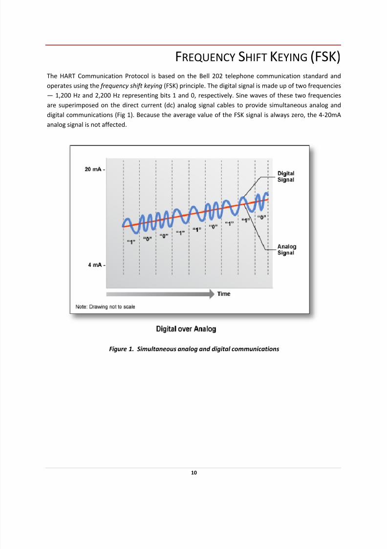
FREQUENCY SHIFT KEYING (FSK) The HART Communication Protocol is based on the Bell 202 telephone communication standard and
operates using the frequency shift keying (FSK) principle. The digital signal is made up of two frequencies
— 1,200 Hz and 2,200 Hz representing bits 1 and 0, respectively. Sine waves of these two frequencies are superimposed on the direct current (dc) analog signal cables to provide simultaneous analog and
digital communications (Fig 1). Because the average value of the FSK signal is always zero, the 4‐20mA
analog signal is not affected.
Figure 1. Simultaneous analog and digital communications
10

7/28/2019 HART Guide
http://slidepdf.com/reader/full/hart-guide 11/174
PHASE SHIFT KEYING (PSK) PSK Physical Layer—higher speed physical layer option—available in HART 6 version of the HART
Protocol. Supports significantly faster communications with standard command/response throughput
up to 10‐12 transactions per second simultaneous with the 4‐20mA signal. Approved specification, but no commercially available chip at present to support implementation in 2 wire devices.
11

7/28/2019 HART Guide
http://slidepdf.com/reader/full/hart-guide 12/174
HART NETWORKS
HART devices can operate in one of two network configurations—point‐to‐point or multidrop.
POINT‐
TO‐POINT
In point‐to‐point mode, the 4‐20mA signal is used to communicate one process variable, while
additional process variables, configuration parameters, and other device data are transferred digitally
using the HART Protocol (Fig 2). The 4‐20mA analog signal is not affected by the HART signal and can be
used for control. The HART communication digital signal gives access to secondary variables and other
data that can be used for operations, commissioning, maintenance and diagnostic purposes.
Figure 2. Point ‐to‐ point communication
12
7/28/2019 HART Guide
http://slidepdf.com/reader/full/hart-guide 13/174
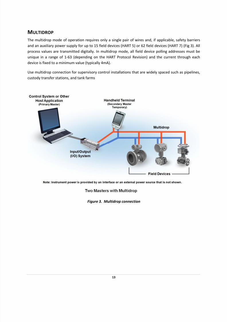
MULTIDROP
The multidrop mode of operation requires only a single pair of wires and, if applicable, safety barriers
and an auxiliary power supply for up to 15 field devices (HART 5) or 62 field devices (HART 7) (Fig 3). All
process values are transmitted digitally. In multidrop mode, all field device polling addresses must be
unique in a range of 1‐63 (depending on the HART Protocol Revision) and the current through each
device is fixed to a minimum value (typically 4mA).
Use multidrop connection for supervisory control installations that are widely spaced such as pipelines,
custody transfer stations, and tank farms
Figure 3. Multidrop connection
13
7/28/2019 HART Guide
http://slidepdf.com/reader/full/hart-guide 14/174
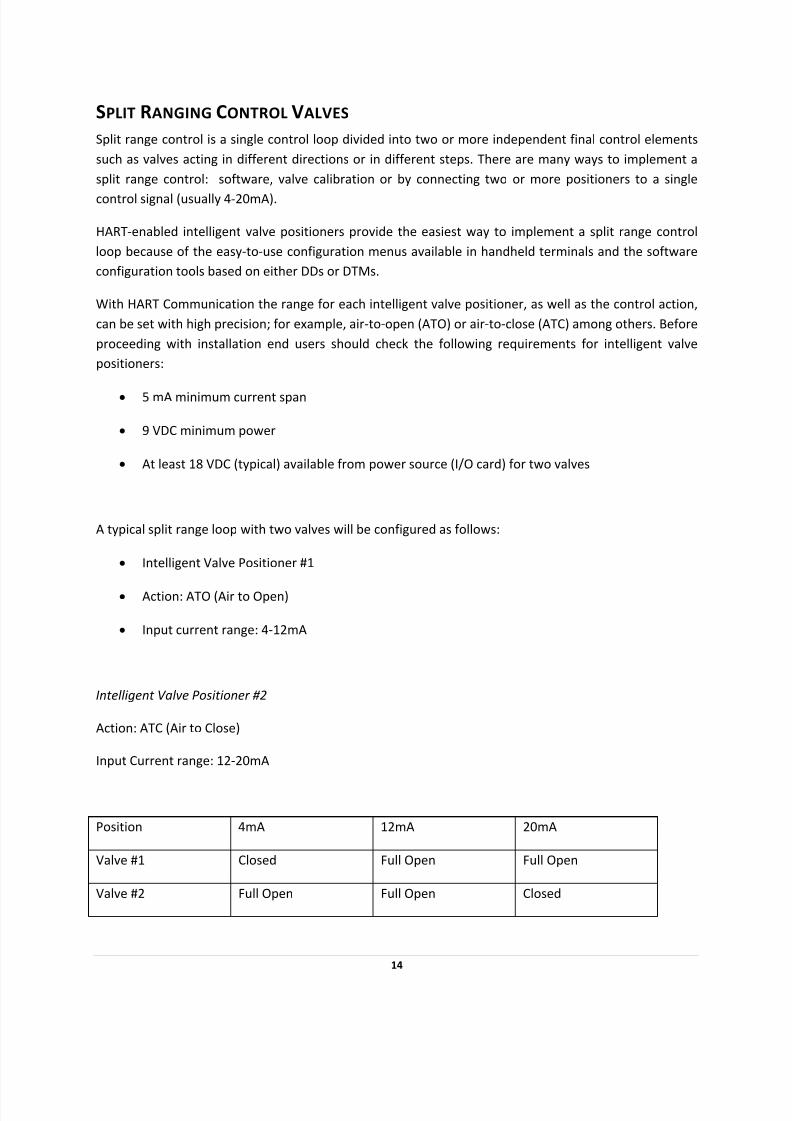
SPLIT RANGING CONTROL VALVES
Split range control is a single control loop divided into two or more independent final control elements
such as valves acting in different directions or in different steps. There are many ways to implement a
split range control: software, valve calibration or by connecting two or more positioners to a single
control signal (usually 4‐20mA).
HART‐enabled intelligent valve positioners provide the easiest way to implement a split range control
loop because of the easy‐to‐use configuration menus available in handheld terminals and the software
configuration tools based on either DDs or DTMs.
With HART Communication the range for each intelligent valve positioner, as well as the control action,
can be set with high precision; for example, air‐to‐open (ATO) or air‐to‐close (ATC) among others. Before
proceeding with installation end users should check the following requirements for intelligent valve
positioners:
• 5 mA minimum current span
• 9 VDC minimum power
• At least 18 VDC (typical) available from power source (I/O card) for two valves
A typical split range loop with two valves will be configured as follows:
• Intelligent Valve Positioner #1
• Action: ATO (Air to Open)
• Input current range: 4‐12mA
Intelligent Valve Positioner #2
Action: ATC (Air to Close)
Input Current range: 12‐20mA
Position 4mA 12mA 20mA
Valve #1 Closed Full Open Full Open
Valve #2 Full Open Full Open Closed
14

7/28/2019 HART Guide
http://slidepdf.com/reader/full/hart-guide 15/174
Setting Loop Addresses for Split Range Systems
When more than one positioner is installed in a single current loop, the HART loop address of each
device must be set to 1, 2, or 3 (or other non‐zero values) to allow a HART master to recognize each
intelligent valve positioner when connected to all three devices on a single current loop. Do not use “0”
for any of the positioners. A “0” may cause HART masters to stop searching for additional positioners.
Figure 4. Split Range with Isolators
15

7/28/2019 HART Guide
http://slidepdf.com/reader/full/hart-guide 16/174

7/28/2019 HART Guide
http://slidepdf.com/reader/full/hart-guide 17/174
CONTROL IN FIELD DEVICES
Microprocessor‐based smart instrumentation enables control algorithms to be calculated in the field
devices, close to the process (Figure 5). Some HART transmitters and actuators support control
functionality in the device, which eliminates the need for a separate controller and reduces hardware,
installation, and start‐up costs. Accurate, closed‐loop control becomes possible in areas where it was
not economically feasible before. While the control algorithm uses the analog signal, HART
communication provides the means to monitor the loop and change control set point and parameters.
Figure 5. Transmitter with PID
Placing control in the field enhances control functionality. Measurement accuracy is maintained because
there is no need to transmit data to a separate controller. Control processing takes place at the high update rate of the sensor and provides enhanced dynamic performance.
17
7/28/2019 HART Guide
http://slidepdf.com/reader/full/hart-guide 18/174
HART FIELD CONTROLLER IMPLEMENTATION
A HART field controller takes advantage of the HART Protocol’s simultaneous analog and digital signaling
by converting the transmitter’s traditional analog measurement output into a control output. The
analog signal from the smart transmitter (controller) is used to manipulate the field device. The analog
output signal also carries the HART digital signal, which is used for monitoring the process
measurement, making set point changes, and tuning the controller.
The communication rate of the HART Protocol (2‐3 updates per second) is generally perceived as too
slow to support closed‐loop control in the central host. With control in the field, the control function no
longer depends on the HART Protocol’s communication rate. Instead, the control signal is an analog
output that is updated at a rate that is much faster than can typically be processed in a conventional
control system. Processing rates vary from 2‐20 updates per second, depending on the product. The
HART digital communication rate remains sufficient for monitoring the control variable and changing set
point values.
18

7/28/2019 HART Guide
http://slidepdf.com/reader/full/hart-guide 19/174
HART COMMANDS
The HART Command Set provides uniform and consistent communication for all field devices. The
command set includes three classes: Universal , Common Practice, and Device Specific ( Table 1). Host
applications may implement any of the necessary commands for a particular application.
UNIVERSAL
All devices using the HART Protocol must recognize and support the universal commands. Universal
commands provide access to information useful in normal operations (e.g., read primary variable and
units).
COMMON PRACTICE
Common Practice commands provide functions implemented by many, but not necessarily all, HART
communication devices.
DEVICE SPECIFIC
Device Specific commands represent functions that are unique to each field device. These commands
access setup and calibration information, as well as information about the construction of the device.
Information on Device Specific commands is available from device manufacturers.
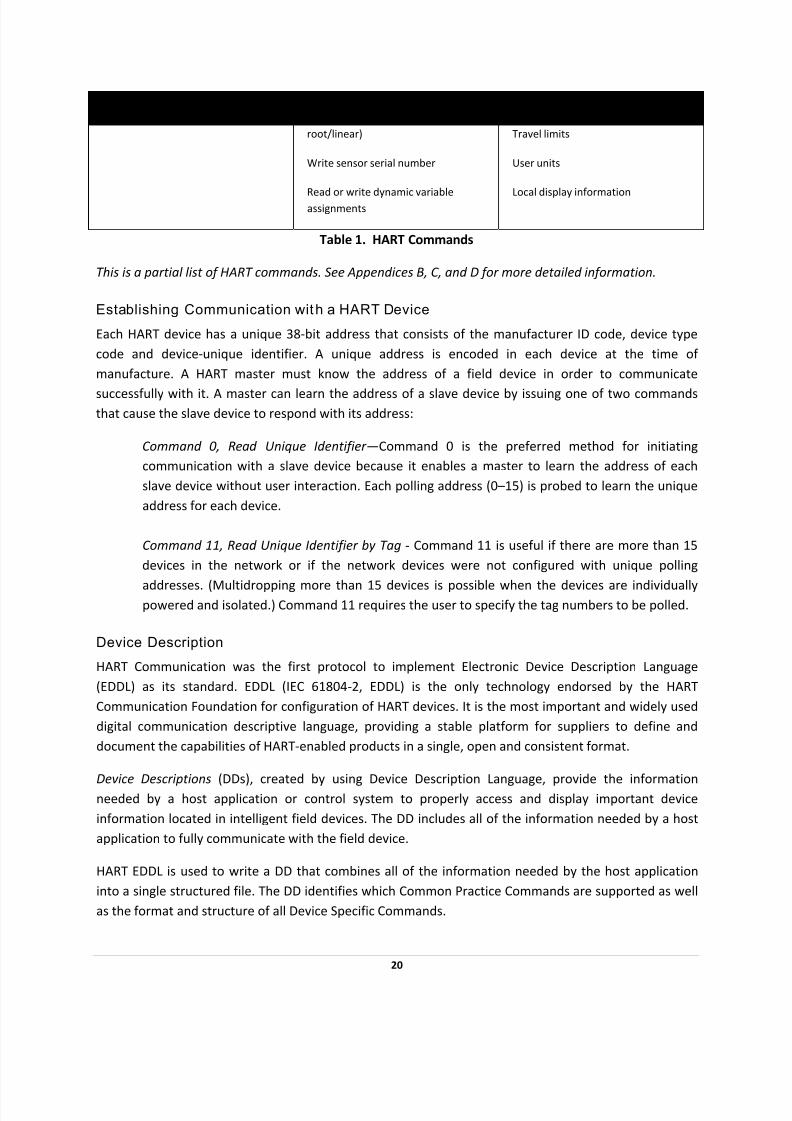
Device Family Summary Table
Universal Commands Common Practice Commands Device Specific Commands
Read manufacturer and device type
Read primary variable (PV) and units
Read current output and percent of
range
Read up to four predefined dynamic
variables
Read or write eight‐character tag, 16‐
character descriptor, date
Read or write 32‐character message
Read device range values, units, and
damping time constant
Read or write final assembly number
Write polling address
Read selection of up to four dynamic
variables
Write damping time constant
Write device range values
Calibrate (set zero, set span)
Set fixed output current
Perform self ‐test
Perform master reset
Trim PV zero
Write PV unit
Trim DAC zero and gain
Write transfer function (square
Read or write low‐flow cut‐off
Start, stop, or clear totalizer
Read or write density calibration factor
Choose PV (mass, flow, or density)
Read or write materials or construction
information
Trim sensor calibration
PID enable
Write PID set point
Valve characterization
Valve set point
19
7/28/2019 HART Guide
http://slidepdf.com/reader/full/hart-guide 20/174
20
Universal Commands Common Practice Commands Device Specific Commands
root/linear)
Write sensor serial number
Read
or
write
dynamic
variable
assignments
Travel limits
User units
Local
display
information
Table 1. HART Commands
This is a partial list of HART commands. See Appendices B, C, and D for more detailed information.
Establishing Communication with a HART Device
Each HART device has a unique 38‐bit address that consists of the manufacturer ID code, device type
code and device‐unique identifier. A unique address is encoded in each device at the time of
manufacture. A HART master must know the address of a field device in order to communicate
successfully with it. A master can learn the address of a slave device by issuing one of two commands that cause the slave device to respond with its address:
Command 0, Read Unique Identifier—Command 0 is the preferred method for initiating
communication with a slave device because it enables a master to learn the address of each
slave device without user interaction. Each polling address (0–15) is probed to learn the unique
address for each device.
Command 11, Read Unique Identifier by Tag ‐ Command 11 is useful if there are more than 15
devices in the network or if the network devices were not configured with unique polling
addresses. (Multidropping more than 15 devices is possible when the devices are individually powered and isolated.) Command 11 requires the user to specify the tag numbers to be polled.
Device Description
HART Communication was the first protocol to implement Electronic Device Description Language
(EDDL) as its standard. EDDL (IEC 61804‐2, EDDL) is the only technology endorsed by the HART
Communication Foundation for configuration of HART devices. It is the most important and widely used
digital communication descriptive language, providing a stable platform for suppliers to define and
document the capabilities of HART‐enabled products in a single, open and consistent format.
Device Descriptions (DDs), created by using Device Description Language, provide the information
needed by a host application or control system to properly access and display important device
information located in intelligent field devices. The DD includes all of the information needed by a host
application to fully communicate with the field device.
HART EDDL is used to write a DD that combines all of the information needed by the host application
into a single structured file. The DD identifies which Common Practice Commands are supported as well
as the format and structure of all Device Specific Commands.
7/28/2019 HART Guide
http://slidepdf.com/reader/full/hart-guide 21/174
A DD for a HART field device is roughly equivalent to an electronic data sheet. DDs eliminate the need
for host suppliers to develop and support custom interfaces and drivers. A DD provides a picture of all
parameters and functions of a device in a standardized language. HART suppliers have the option of
supplying a DD for their HART field product. If they choose to supply one, the DD will provide
information for a DD‐enabled host application to read and write data according to each device’s
procedures.
DD source files for HART devices resemble files written in the C programming language. DD files are
submitted to the HCF for registration in the HCF DD Library. Quality checks are performed on each DD
submitted to ensure specification compliance, to verify that there are no conflicts with DDs already
registered, and to verify operation with standard HART hosts. The HCF DD Library is the central location
for management and distribution of all HART DDs to facilitate use in host applications such as PCs and
handheld terminals.
DDs can be downloaded at www.hartcomm.org.
21

7/28/2019 HART Guide
http://slidepdf.com/reader/full/hart-guide 22/174
BENEFITS OF HART COMMUNICATION
The HART Protocol is a powerful communication technology used to exploit the full potential of digital
field devices. Preserving the traditional 4‐20 mA signal, the HART Protocol extends system capabilities
for two‐way digital communication with smart field instruments.
The HART protocol offers the best solution for smart field device communications and has the widest
base of support of any field device protocol worldwide. More instruments are available with the HART
protocol than any other digital communications technology. Almost any process application can be
addressed by one of the products offered by HART instrument suppliers.
Unlike other digital communication technologies, the HART Protocol provides a unique communication
solution that is backward compatible with the installed base of instrumentation in use today. This
backward compatibility ensures that investments in existing cabling and current control strategies will
remain secure well into the future.
Benefits outlined in this section include:
• Improved plant operations
• Operational flexibility
• Instrumentation investment protection
22

7/28/2019 HART Guide
http://slidepdf.com/reader/full/hart-guide 23/174
IMPROVED PLANT OPERATIONS
The HART Protocol improves plant performance and increases efficiencies in:
• Commissioning and installation
• Plant operations
• Maintenance
COST SAVINGS IN COMMISSIONING
HART‐based field devices can be installed and commissioned in a fraction of the time required for a
traditional analog‐only system. Operators who use HART digital communications can easily identify a
field device by its tag and verify that operational parameters are correct. Configurations of similar
devices can be copied to streamline the commissioning process. A loop integrity check is readily
accomplished by commanding the field transmitter to set the analog output to a preset value.
COST SAVINGS IN INSTALLATION
The HART Protocol supports the networking of several devices on a single twisted wire pair. This
configuration can provide significant savings in wiring, especially for applications such as tank
monitoring.
Multivariable devices reduce the number of instruments, wiring, spare parts, and terminations required.
Some HART field instruments embed PID control, which eliminates the need for a separate controller,
and results in significant wiring and equipment cost savings.
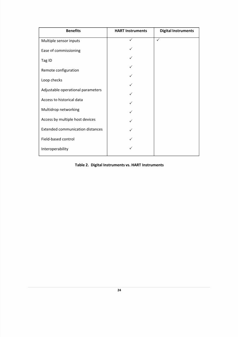
DIGITAL COMMUNICATION
A digital instrument that uses a microprocessor provides many benefits. These benefits are found in all
smart devices regardless of the type of communication used. A digital device provides advantages such
as improved accuracy and stability. The HART Protocol enhances the capabilities of digital instruments
by providing communication access and networking (Table 2).
Benefits HART Instruments Digital Instruments
Accuracy and stability
Reliability
Multivariable
Computations
Diagnostics
3
3
3
3
3
3
3
3
3
3
23
7/28/2019 HART Guide
http://slidepdf.com/reader/full/hart-guide 24/174
24
Benefits HART Instruments Digital Instruments
Multiple sensor inputs
Ease of commissioning
Tag ID
Remote configuration
Loop checks
Adjustable operational parameters
Access to historical data
Multidrop networking
Access by multiple host devices
Extended communication distances
Field‐based control
Interoperability
3
3
3
3
3
3
3
3
3
3
3
3
3
3
Table 2. Digital Instruments vs. HART Instruments

7/28/2019 HART Guide
http://slidepdf.com/reader/full/hart-guide 25/174
IMPROVED MEASUREMENT Q UALITY
HART‐communicating devices provide accurate information that helps improve the efficiency of plant
operations. During normal operation, device operational values can be easily monitored or modified
remotely. If uploaded to a software application, these data can be used to automate record keeping for
regulatory compliance (e.g., environmental, validation, ISO9000, and safety standards).
Numerous device parameters are available from HART‐compatible instruments that can be
communicated to the control room and used for control, maintenance, and record keeping (Fig 6).
Figure 6. Examples of Device Parameters Sent to Control Room
Some HART devices perform complex calculations, such as PID control algorithms or compensated flow
rate. Multivariable HART‐capable instruments take measurements and perform calculations at the
source, which eliminates time bias and results in more accurate calculations than are possible when
performed in a centralized host.
The HART Protocol provides access to all information in multivariable devices.
In addition to the analog output (primary variable), the HART Protocol provides
access to all measurement data that can be used for verification or
calculation of plant mass and energy balances.
Some HART field devices store historical information in the form of trend logs and summary data. These
logs and statistical calculations (e.g., high and low values and averages) can be uploaded into a software
application for further processing or record keeping.
25

7/28/2019 HART Guide
http://slidepdf.com/reader/full/hart-guide 26/174
COST SAVINGS IN MAINTENANCE
The diagnostic capabilities of HART‐communicating field devices can eliminate substantial costs by
reducing downtime. The HART Protocol communicates diagnostic information to the control room,
which minimizes the time required to identify the source of any problem and take corrective action.
Trips into the field or hazardous areas are eliminated or reduced.
When a replacement device is put into service, HART communication allows the correct operational
parameters and settings to be quickly and accurately uploaded into the device from a central database.
Efficient and rapid uploading reduces the time that the device is out of service. Some software
applications provide a historical record of configuration and operational status for each instrument. This
information can be used for predictive, preventive and proactive maintenance.
26
7/28/2019 HART Guide
http://slidepdf.com/reader/full/hart-guide 27/174
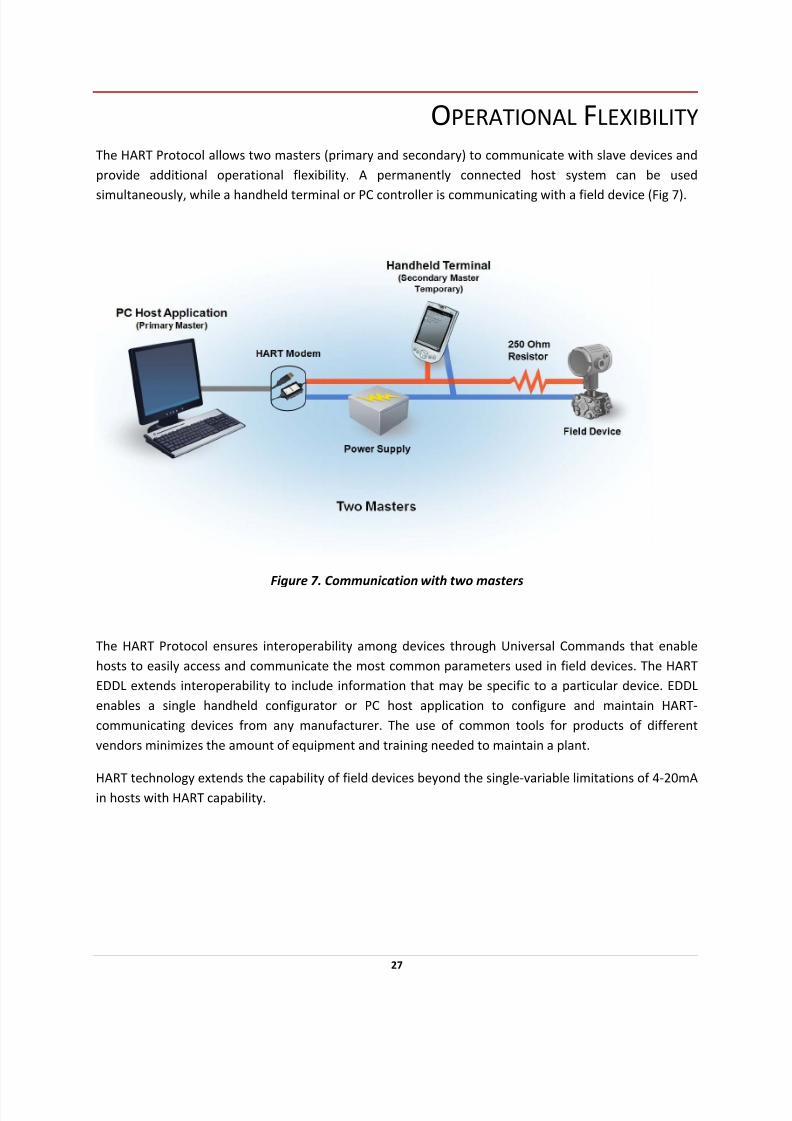
OPERATIONAL FLEXIBILITY
The HART Protocol allows two masters (primary and secondary) to communicate with slave devices and
provide additional operational flexibility. A permanently connected host system can be used
simultaneously, while a handheld terminal or PC controller is communicating with a field device (Fig 7).
Figure 7. Communication with two masters
The HART Protocol ensures interoperability among devices through Universal Commands that enable
hosts to easily access and communicate the most common parameters used in field devices. The HART
EDDL extends interoperability to include information that may be specific to a particular device. EDDL
enables a single handheld configurator or PC host application to configure and maintain HART‐
communicating devices from any manufacturer. The use of common tools for products of different
vendors minimizes the amount of equipment and training needed to maintain a plant.
HART technology extends the capability of field devices beyond the single‐variable limitations of 4‐20mA
in hosts with HART capability.
27
7/28/2019 HART Guide
http://slidepdf.com/reader/full/hart-guide 28/174
INSTRUMENTATION INVESTMENT PROTECTION
Existing plants and processes have considerable investments in wiring, analog controllers, junction
boxes, barriers, marshalling panels, and analog or smart instrumentation. The people, procedures and
equipment already exist for the support and maintenance of the installed equipment. HART field instruments protect this investment by providing compatible products with enhanced digital
capabilities. These enhanced capabilities can be used incrementally.
The HART Communication Protocol enables you to retain your previous
Investments in existing hardware and personnel.
At the basic level, HART devices communicate with a handheld terminal for setup and maintenance. As
needs grow, more sophisticated on‐line, PC‐based systems can provide continuous monitoring of device
status and configuration parameters. Advanced installations can also use control systems with HART I/O
capability. The status information can be used directly by control schemes to trigger remedial actions
and allow on‐line re‐ranging based on operating conditions and direct reading of multivariable
instrument data.
COMPATIBILITY OF HART REVISIONS
As HART field devices are upgraded, new functions may be added. A basic premise of the HART Protocol
is that new HART instruments must behave in precisely the same manner as older versions when
interfaced with an earlier revision host system.
28
7/28/2019 HART Guide
http://slidepdf.com/reader/full/hart-guide 29/174
GETTING THE MOST OUT OF HART SYSTEMS To take full advantage of the benefits offered by the HART Communication Protocol, it is important that
you install and implement the system correctly. The following section contains information that can help
you to get the most from your HART system:
• Wiring and Installation
• Intrinsic safety (IS)
• HART multidrop networks
• Control system interfaces
• Multiplexers
• Reading HART data into non‐HART systems
• Commissioning HART networks
• Device status and diagnostics
• Connecting a PC to a HART device or network
29

7/28/2019 HART Guide
http://slidepdf.com/reader/full/hart-guide 30/174
WIRING AND INSTALLATION
In general, the installation practice for HART communicating devices is the same as conventional 4‐
20mA instrumentation. Individually shielded twisted pair cable, either in single‐pair or multi‐pair
varieties, is the recommended wiring practice. Unshielded cables may be used for short distances if ambient noise and cross‐talk will not affect communication. The minimum conductor size is 0.51 mm
diameter (#24 AWG) for cable runs less than 1,524 m (5,000 ft) and 0.81 mm diameter (#20 AWG) for
longer distances.
CABLE LENGTH
Most installations are well within the 3,000 meter (10,000 ft) theoretical limit for HART communication.
However, the electrical characteristics of the cable (mostly capacitance) and the combination of
connected devices can affect the maximum allowable cable length of a HART network. Table 3 shows
the affect of cable capacitance and the number of network devices on cable length. The table is based
on typical installations of HART devices in non‐IS environments, i.e. no miscellaneous series impedance.
Detailed information for determining the maximum cable length for any HART network configuration
can be found in the HART Physical Layer Specifications.
Cable Capacitance – pf/ft (pf/m)
Cable Length – feet (meters)
No. Network
Devices
20 pf/ft
(65 pf/m)
30 pf/ft
(95 pf/m)
50 pf/ft
(160 pf/m)
70 pf/ft
(225 pf/m)
1 9,000 ft
(2,769 m)
6,500 ft
(2,000 m)
4,200 ft
(1,292 m)
3,200 ft
(985 m)
5 8,000 ft
(2,462 m)
5,900 ft
(1,815 m)
3,700 ft
(1,138 m)
2,900 ft
(892 m)
10 7,000 ft
(2,154 m)
5,200 ft
(1,600 m)
3,300 ft
(1,015 m)
2,500 ft
(769 m)
15 6,000 ft
(1,846 m)
4,600 ft
(1,415 m)
2,900 ft
(892 m)
2,300 ft
(708 m)
Table 3. Allowable cable lengths for 1.02 mm (#18 AWG) shield twisted pair
30

7/28/2019 HART Guide
http://slidepdf.com/reader/full/hart-guide 31/174
INTRINSIC SAFETY
Intrinsic safety (IS) is a method of providing safe operation of electronic process‐control instrumentation
in hazardous areas. IS systems keep the available electrical energy in the system low enough that
ignition of the hazardous atmosphere cannot occur. No single field device or wiring is intrinsically safe by itself (except for battery‐operated, self ‐contained devices), but is intrinsically safe only when employed
in a properly designed IS system.
INTRINSIC SAFETY DEVICES
HART‐communicating devices work well in applications that require IS operation. IS devices (e.g.,
barriers) are often used with traditional two‐wire 4‐20 mA instruments to ensure an IS system in
hazardous areas. With traditional analog instrumentation, energy to the field can be limited with or
without a ground connection by installing one of the following IS devices:
• Shunt ‐diode
(zener)
barriers that use a high‐quality safety ground connection to bypass
excess energy (Fig 8)
• Isolators, which do not require a ground connection, that repeat the analog
measurement signal across an isolated interface in the safe‐side load circuit (Fig 8‐A).
Both zener barriers and isolators can be used to ensure an IS system with HART‐communicating devices,
but some additional issues must be considered when engineering the HART loop.
Figure 8. 4‐20mA Loop with Zener Barrier
Figure 8 ‐ A. 4‐20mA Loop with Isolator
31

7/28/2019 HART Guide
http://slidepdf.com/reader/full/hart-guide 32/174
DESIGNING AN IS SYSTEM USING SHUNT‐DIODE BARRIERS
Designing an IS direct‐current loop simply requires ensuring that a field device has sufficient voltage to
operate, taking into account zener barrier resistance, the load resistor, and any cable resistance.
When designing an IS loop using shunt‐diode barriers, two additional requirements must be considered:
• The power supply must be reduced by an additional 0.7 V to allow headroom for the
HART communication signal and yet not approach the zener barrier conduction voltage.
• The load resistor must be at least 230 Ω (typically 250 Ω).
Depending on the lift‐off voltage of the transmitter (typically 10–12 V), these two requirements can be
difficult to achieve. The loop must be designed to work up to 22 mA (not just 20 mA) to communicate
with a field device that is reporting failure by an upscale, over‐range current. The series resistance for
the same zener barrier may be as high as 340 Ω. To calculate the available voltage needed to power a
transmitter, use the following equation:
• Power Supply Voltage – (Zener Barrier Resistance + Sense Resistance) × Operating Current (mA)
= Available Voltage
Example: 26.0 V – (340 Ω + 250 Ω) × 22mA = 13.0 V
Any cable resistance can be added as a series resistance and will reduce the voltage even further. In
addition, the power supply to the zener barrier must also be set lower than the zener barrier conduction
voltage. For example, a 28 V, 300 Ω zener barrier would typically be used with a 26 V power supply.
While it is difficult to meet the two requirements noted above for a network using shunt‐diode barriers,
it
can
be
done.
Following
are
two
possible
solutions
to
the
problem:
Shunt the load resistor with a large inductor so that the load resistor impedance is still high (and
mainly resistive) at HART signal frequencies, but much lower at direct current. This solution,
while it does work, is physically somewhat inconvenient.
Use an IS isolator rather than a shunt‐diode barrier. The output voltage on the hazardous side is
usually specified as greater than X Vdc at 20mA (typically 14‐17 V). This value already includes
the voltage drop due to the internal safety resistor, so the only extra voltage drop is that due to
cable resistance. System operation at 22mA requires reducing the 20mA voltage by 0.7 V (340 Ω
× 2mA).
DESIGNING AN IS SYSTEM USING ISOLATORS
The implementation of HART loops in an IS system with isolators requires more planning. An isolator is
designed to recreate the 4‐20mA signal from the field device in the safe‐side load circuit. Most older
isolator designs will not carry the high frequencies of HART current signals across to the safe side, nor
will they convey HART voltage signals from the safe side to the field. For this reason, HART
32
7/28/2019 HART Guide
http://slidepdf.com/reader/full/hart-guide 33/174
communication through the isolator is not possible with these older designs. (It is still possible to work
with a handheld communicator or a PC with an IS modem on the hazardous side of the isolator.) When
retrofitting HART instruments into an existing installation, inspect the system for isolators that may have
to be replaced (any isolators that will not support HART signals).
Major suppliers of IS isolators have introduced designs that are fully HART compatible. Modern IS isolators provide trouble‐free design and operation and transparent communication in both directions.
IS device suppliers can assist with certification and performance specifications for their HART‐
compatible products. Field device manufacturers will also supply certification details for their specific
products.
MULTIDROP IS NETWORKS
HART multidrop networks are particularly suitable for intrinsically safe installations. With a multidrop
configuration, fewer barriers or isolators are required. In addition, because each field device takes only
4mA (for a total of 16mA in a four‐device loop), plain zener barriers can be used. With a 250 Ω load, 25 V
– (340 + 250 Ω × 16mA = 15.5 V , which is well above the transmitter lift‐off voltage and leaves a margin
for cable resistance.
IS OUTPUT LOOPS
For output devices such as valve positioners, direct‐current voltage considerations will vary depending
on the drive requirements of the device. Zener barriers may be possible. If not, modern HART‐
compatible output isolators are appropriate.
IS CERTIFICATION CONSIDERATIONS
If the HART loop contains an IS‐approved handheld communicator or modem, slight changes may be
needed to meet IS installation certification rules. Handheld communicators and modems add the HART
signal voltage to the voltage level coming from the zener barrier or isolator. For example, a handheld
communicator typically adds a maximum of 2 V to the loop. Therefore, when used with a 28V zener
barrier, a total of 30V may theoretically be present in the loop. The allowable capacitance must be
reduced by about 15% to account for this increase in voltage.
IS NETWORK CABLE LENGTH CALCULATIONS
The cable length calculation must include the resistance of both the zener barrier and the load resistor.
33

7/28/2019 HART Guide
http://slidepdf.com/reader/full/hart-guide 34/174
SAFETY INTEGRITY LEVEL (SIL)
When performing a risk analysis on a process operation, each loop is analyzed for its potential
contribution to an unsafe condition should a failure occur. This assessment will define an acceptable
Safety Integrity Level (SIL) for each loop in that process. Using continuous HART Communication allows
the diagnosis of potentially dangerous failures and conditions to be significantly increased which
increases the SIL.
Every device in a loop has potential failure conditions. Sometimes increased maintenance will insure a
higher degree of reliability. For many devices, online diagnoses of failures or potentially dangerous
conditions are required to insure the level of reliability demanded by the SIL of the process.
It is up to the design team to select the proper products and procedures to demonstrate the
achievement of the required SIL. Guidelines are offered in the ISA Standard SP84.01 and in the IEC
standard 61508 for methods to improve loop reliability.
34

7/28/2019 HART Guide
http://slidepdf.com/reader/full/hart-guide 35/174
HART MULTIDROP NETWORKS
The HART Communication Protocol enables several instruments to be connected on the same pair of
wires in a multidrop network configuration (Fig 9). The current through each field device is fixed at a
minimum value (typically 4mA) sufficient for device operation. The analog loop current does not change in relation to the process and thus does not reflect the primary variable. Communications in multidrop
mode are entirely digital.
Figure 9. Multidrop Configuration
Standard HART commands are used to communicate with field instruments to determine process
variables or device parameter information (see HART Commands on page 19). The typical cycle time
needed to read information on a single variable from a HART device is approximately 500 milliseconds
(ms). For a network of 15 devices, a total of approximately 7.5 seconds is needed to scan and read the
primary variables from all devices. Reading information from multivariable instruments may take longer, as the data field will typically contain values for four variables rather than just one.
The typical multidrop network enables two‐wire measurement devices to be connected in parallel. Two‐
wire loop‐powered and four‐wire active‐source devices can be connected in the same network. If both
two‐ and four‐wire devices are used in the same network, three wires must be used to properly connect
the devices (see Water Treatment Facility Upgrade on page 158).
35

7/28/2019 HART Guide
http://slidepdf.com/reader/full/hart-guide 36/174
MULTIDROP WITH HART FIELD CONTROLLERS
HART field controllers can also be wired in a multidrop network (Fig 10). Each analog output signal from
the transmitter/controllers is isolated from every other output signal, which provides a cost‐effective
HART network configuration. In this case, the analog signals are not fixed and are used for the output
signal to the controlled device.
Figure 10. HART controllers with multidrop
36
7/28/2019 HART Guide
http://slidepdf.com/reader/full/hart-guide 37/174
7/28/2019 HART Guide
http://slidepdf.com/reader/full/hart-guide 38/174
CONTROL SYSTEM INTERFACES
When you change your existing control system by adding a HART interface, it is important to understand
the complete functionality offered by the HART interface. While several control system suppliers offer
HART interfaces, not all interfaces provide the same functionality.
Control systems such as a DCS, PLC, or SCADA/RTU (remote terminal unit) implement only the
functionality required for a given application. For example, a flow control system may only read the
primary variable of a device and provide no additional support for viewing or changing configuration
information. Other control system interfaces provide comprehensive HART support, maintaining
complete configuration records for all connected devices.
Contact your system supplier for specific details on their HART interface(s). Use the form in Appendix A
to obtain information from control system suppliers to identify specific characteristics of their products.
HART I/O SUBSYSTEMS
Many HART‐compatible I/O subsystems have multiple analog channels on each I/O card. Suppliers
choose whether to provide one HART interface per channel or to share one HART interface among
several channels. The number of shared channels per HART interface impacts the frequency of data
updates from a HART field device and the HART functionality that is supported.
HART I/O FOR MULTIDROP SUPPORT
For the best performance and flexibility, one HART interface should be dedicated to each I/O channel.
Systems that share only one HART interface among several I/O channels may not support multidrop
networks. The effective update rate of a multiplexed interface is slow enough that the performance of
multiplexed multidrop networks would not be practical. Some suppliers enable multidrop support by
fixing the HART interface to one specific I/O channel. However, the other channels on that card may
then not be available for HART communication.
HART I/O FOR BURST MODE SUPPORT
Burst mode is an optional implementation in a field device. Receiving burst mode messages is optional
in a host as well. To take full advantage of burst mode, the I/O system should have one HART interface
for each channel. If the HART interface is shared by more than one channel, messages sent by the field
device may not be detected by the control system. If the system does not have the ability to configure
burst mode in the field device, a handheld terminal or other configuration tool is required.
38
7/28/2019 HART Guide
http://slidepdf.com/reader/full/hart-guide 39/174
DATA HANDLING
All HART‐compatible control systems can read the digital primary variable from a slave device. However,
some system architectures may not be able to accommodate textual data (e.g., tag and descriptor
fields). In these cases, the controller is able to read the process variable, but may not have direct access
to all other data in the HART device.
PASS‐THROUGH FEATURE
Some control systems are integrated with a configuration or instrument management application. In
these systems, the control system passes a HART command, issued by the management application, to
the field device via its I/O interface. When the control system receives the reply from the field device, it
sends the reply to the management application. This function is referred to as a pass‐through feature of
the control system.
GATEWAYS
Gateways can be used to bring HART digital data into control systems that do not support HART‐capable
I/O. Some systems support HART gateways with communication protocols such as Modbus, PROFIBUS
DP, or TCP/IP Ethernet. The typical HART gateway supports all Universal Commands and a subset of the
Common Practice Commands. Support varies depending on the gateway supplier. Some gateways
support access to Device Specific information.
SCADA/RTU SYSTEMS
RTUs used in SCADA systems use a special telemetry to communicate with the control system. RTUs
have the same considerations regarding multidrop and burst mode support as other systems. However, implementation is made more complex because RTUs often communicate to an upper‐level host using a
communication protocol other than HART (e.g., Modbus). While there are many benefits to
implementing HART in an RTU (support of multidrop, burst mode, and multivariable instruments), HART
data are only available to the central host system if the telemetry protocol supports the transfer of
HART commands or specific HART data (see Multidrop for Tank Farm Monitoring – Page 53).
39
7/28/2019 HART Guide
http://slidepdf.com/reader/full/hart-guide 40/174
MULTIPLEXERS
HART‐compatible multiplexers are ideal for users who want to interface with a large number of HART
devices. Multiplexers can be modular and are capable of supporting both point‐to‐point and all‐digital
(multidrop) HART communication modes. Communication between a multiplexer and a host application depends on the multiplexer capabilities (e.g., RS232C, RS485, Modbus, and TCP/IP Ethernet).
When installing HART multiplexer systems, the following capabilities should be considered:
• Number of HART channels supported
• Number of HART channels that share a HART modem
• Burst mode support
• Multidrop support
• Method of communication with the host computer or control system
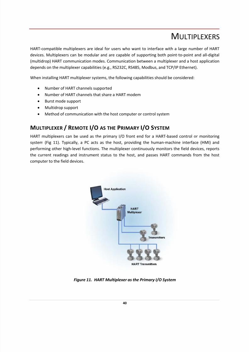
MULTIPLEXER / REMOTE I/O AS THE PRIMARY I/O SYSTEM
HART multiplexers can be used as the primary I/O front end for a HART‐based control or monitoring
system (Fig 11). Typically, a PC acts as the host, providing the human‐machine interface (HMI) and
performing other high‐level functions. The multiplexer continuously monitors the field devices, reports
the current readings and instrument status to the host, and passes HART commands from the host
computer to the field devices.
Figure 11. HART Multiplexer as the Primary I/O System
40
7/28/2019 HART Guide
http://slidepdf.com/reader/full/hart-guide 41/174
PARALLEL MONITORING WITH A MULTIPLEXER
When a traditional 4‐20 mA control system is using the analog signals for measurement and control
outputs, a HART multiplexer can be added to the network to gain access to the digital HART signal. Using
a multiplexer enables a supervisory computer to monitor diagnostics and device status, access
configuration information, and read any additional process inputs or calculations not provided by the 4‐20mA signal.
Use a HART multiplexer to gain access to the digital HART signal
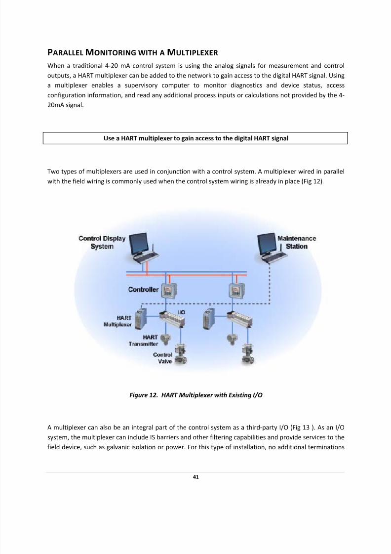
Two types of multiplexers are used in conjunction with a control system. A multiplexer wired in parallel
with the field wiring is commonly used when the control system wiring is already in place (Fig 12).
Figure 12. HART Multiplexer with Existing I/O
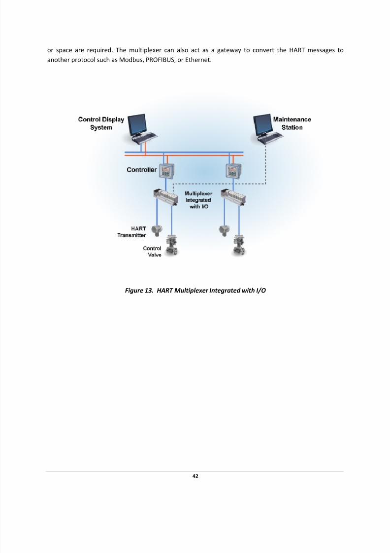
A multiplexer can also be an integral part of the control system as a third‐party I/O (Fig 13 ). As an I/O
system, the multiplexer can include IS barriers and other filtering capabilities and provide services to the
field device, such as galvanic isolation or power. For this type of installation, no additional terminations
41
7/28/2019 HART Guide
http://slidepdf.com/reader/full/hart-guide 42/174
or space are required. The multiplexer can also act as a gateway to convert the HART messages to
another protocol such as Modbus, PROFIBUS, or Ethernet.
Figure 13.
HART
Multiplexer
Integrated
with
I/O
42

7/28/2019 HART Guide
http://slidepdf.com/reader/full/hart-guide 43/174
HART OVER PROFIBUS
HART field devices can be seamlessly integrated with PROFIBUS DP networks using the HART/DP Link,
which enables the connection of four HART devices and facilitates the passthrough of HART commands
to host applications on the DP network (Fig 14). The HART/DP Link supports IS installations.
Figure 14. HART over PROFIBUS
43

7/28/2019 HART Guide
http://slidepdf.com/reader/full/hart-guide 44/174
READING HART DATA INTO NON‐HART SYSTEMS
Many HART products are able to perform more than one measurement or output function (e.g., make
multiple process measurements, calculate process information, and provide positioner feedback
information). All of this information can be easily accessed digitally. However, existing controllers or interface equipment may not have the ability to read digital HART data. Products are available that can
read HART digital signals and convert them to analog (4‐20mA) and alarm trip (contact closure)
information, which enables any traditional analog control system to take full advantage of the benefits
of HART‐communicating devices.
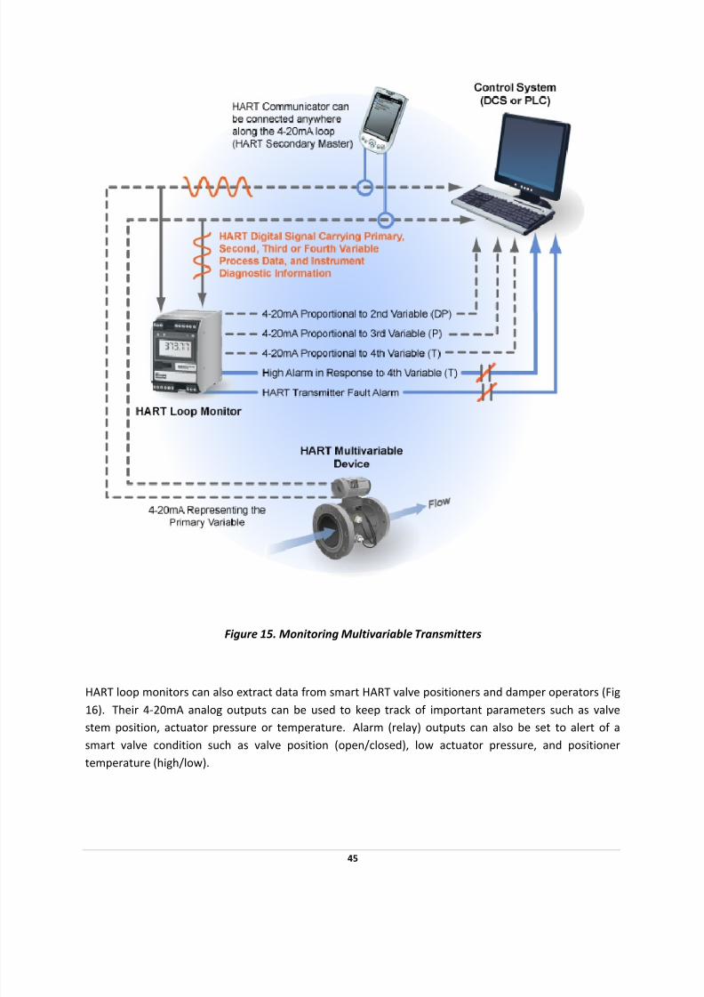
The HART loop monitor continuously communicates with any HART‐capable device and provides
multiple analog outputs (4‐20mA) and multiple alarm trip (contact closure) outputs based on the
information received (Fig 15). For example, smart HART multivariable mass flow transmitters sense
three
process
variables
(pressure,
temperature,
and
differential
pressure
or
raw
flow).
Using
these,
they
perform an internal calculation to derive mass flow. The mass flow information is transmitted as a 4‐
20mA signal to the control system. However, there is no way to continuously monitor the non‐primary
variables used to make the calculation.
Installed transparently across the 4‐20mA instrument loop, the HART loop monitor reads the HART
digital data that is continuously being transmitted on the smart transmitter’s analog loop wires, and
converts it to 4‐20mA signals that can be readily accepted by a DCS or PLC. This allows continuous
tracking of a multivariable transmitter’s second, third and fourth variables. HART loop monitors can also
provide alarm trip (contact closure) information to warn of high and/or low process conditions based on
user‐set trip points. Diagnostic alarms can be set to warn of problems with a smart HART transmitter
using the Field Device Status data that is available in HART’s digital information.
44
7/28/2019 HART Guide
http://slidepdf.com/reader/full/hart-guide 45/174
Figure 15. Monitoring Multivariable Transmitters
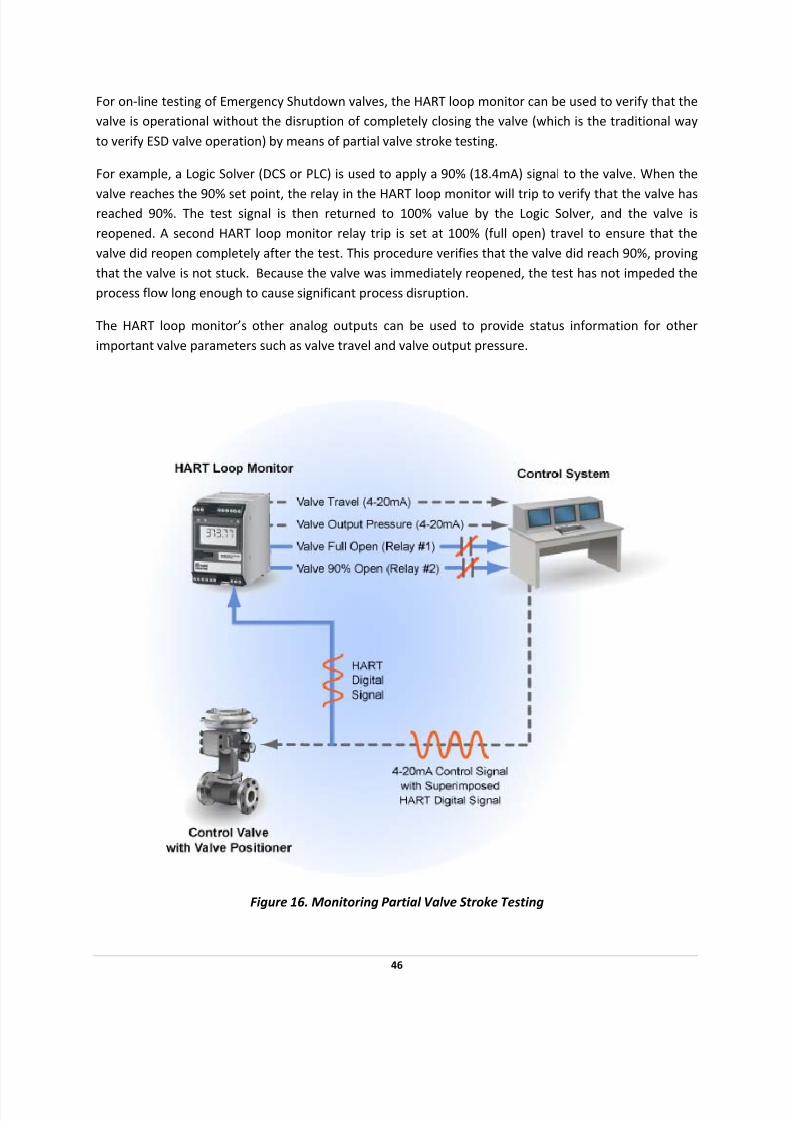
HART loop monitors can also extract data from smart HART valve positioners and damper operators (Fig
16). Their 4‐20mA analog outputs can be used to keep track of important parameters such as valve
stem position, actuator pressure or temperature. Alarm (relay) outputs can also be set to alert of a
smart valve condition such as valve position (open/closed), low actuator pressure, and positioner
temperature (high/low).
45
7/28/2019 HART Guide
http://slidepdf.com/reader/full/hart-guide 46/174
For on‐line testing of Emergency Shutdown valves, the HART loop monitor can be used to verify that the
valve is operational without the disruption of completely closing the valve (which is the traditional way
to verify ESD valve operation) by means of partial valve stroke testing.
For example, a Logic Solver (DCS or PLC) is used to apply a 90% (18.4mA) signal to the valve. When the
valve reaches the 90% set point, the relay in the HART loop monitor will trip to verify that the valve has reached 90%. The test signal is then returned to 100% value by the Logic Solver, and the valve is
reopened. A second HART loop monitor relay trip is set at 100% (full open) travel to ensure that the
valve did reopen completely after the test. This procedure verifies that the valve did reach 90%, proving
that the valve is not stuck. Because the valve was immediately reopened, the test has not impeded the
process flow long enough to cause significant process disruption.
The HART loop monitor’s other analog outputs can be used to provide status information for other
important valve parameters such as valve travel and valve output pressure.
Figure 16. Monitoring Partial Valve Stroke Testing
46

7/28/2019 HART Guide
http://slidepdf.com/reader/full/hart-guide 47/174
COMMISSIONING HART NETWORKS
HART‐based instruments have several features that significantly reduce the time required to fully
commission a HART network (loop). When less time is required for commissioning, substantial cost
savings are achieved.
DEVICE VERIFICATION
Before installation, manufacturers usually enter device tags and other identification and configuration
data into each field instrument. After installation, the instrument identification (tag and descriptor) can
be verified in the control room using a configurator (handheld terminal or PC). Some field devices
provide information on their physical configuration (e.g., wetted materials)—these and other
configuration data can also be verified in the control room. The verification process can be important in
conforming to governmental regulations and ISO quality requirements.
The commissioning process can be further streamlined by connecting a PC configurator to each HART
loop online, either by integration with the control system or by using one of the many available HART
multiplexing I/O systems (see Multiplexers). With this centralized approach, there is no need to move
the configuration device from one termination point to the next while commissioning all devices on the
network.
LOOP INTEGRITY CHECK
Once a field instrument has been identified and its configuration data confirmed, the analog loop
integrity can be checked using the loop test feature, which is supported by many HART devices. The loop
test feature enables the analog signal from a HART transmitter to be fixed at a specific value to verify loop integrity and ensure proper connection to support devices such as indicators, recorders, and DCS
displays.
Use the HART Protocol loop test feature to check analog loop integrity and ensure
a proper physical connection among all network devices.
AS‐INSTALLED RECORD KEEPING
A HART configurator also facilitates record keeping. As installed device configuration data can be stored
in memory or on a disk for later archiving or printing.
47
7/28/2019 HART Guide
http://slidepdf.com/reader/full/hart-guide 48/174
DEVICE STATUS AND DIAGNOSTICS
Most HART field instruments provide both status information and diagnostic information. The HART
Protocol defines basic status information as information that is included with every message from a field
device. Basic status information enables the host application to immediately identify warning or error conditions detected by the field device. Status messages also enable the user to differentiate between
measurements that are outside sensor or range limits and actual hardware malfunctions. Examples of
status messages are:
• Field device malfunction
• Configuration changed
• Cold start
• More status available
• Analog output current fixed
• Analog output saturated • Non‐primary variable out of limits
• Primary variable out of limits
HART instruments can implement extensive, device‐specific diagnostics. The amount and type of
diagnostic information is determined by the manufacturer and varies with product and application.
Diagnostic information can be accessed using the HART Communication Protocol. Host applications
using DD files can interpret and display diagnostic information. Applications not using DD technology
may require product‐specific software modules to interpret diagnostic information.
Many manufacturers offer special software applications for their own products. Some modules allow
you to customize for specific products. Manufacturers of valve actuators have made extensive use of
this capability to provide preventative and predictive diagnostic information that greatly enhances the
value of their products as compared to conventional actuators.
Several software applications are available that provide continuous communication with field devices
using a HART‐compatible multiplexer and HART I/O (see Multiplexers). These applications provide real‐
time monitoring of status and diagnostic information.
48
7/28/2019 HART Guide
http://slidepdf.com/reader/full/hart-guide 49/174
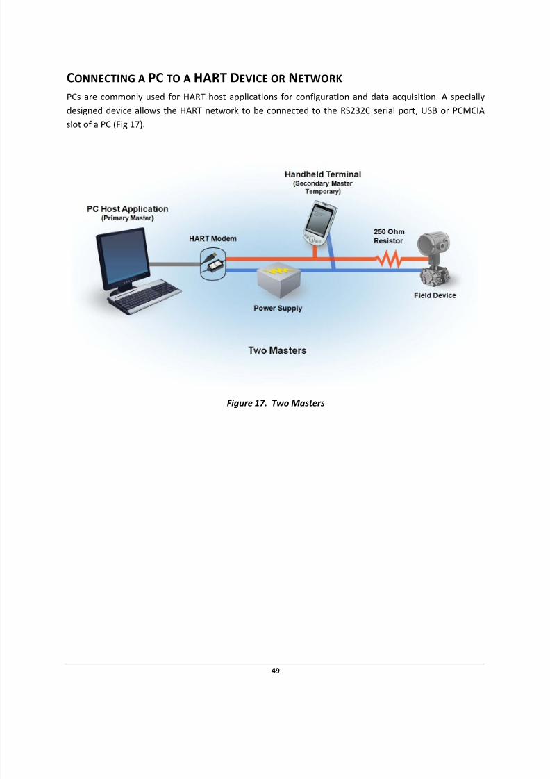
CONNECTING A PC TO A HART DEVICE OR NETWORK
PCs are commonly used for HART host applications for configuration and data acquisition. A specially
designed device allows the HART network to be connected to the RS232C serial port, USB or PCMCIA
slot of a PC (Fig 17).
Figure 17. Two Masters
49
7/28/2019 HART Guide
http://slidepdf.com/reader/full/hart-guide 50/174
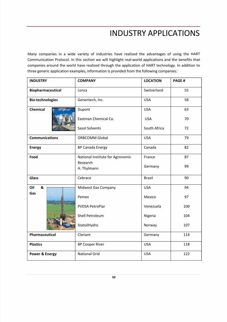
INDUSTRY APPLICATIONS
Many companies in a wide variety of industries have realized the advantages of using the HART
Communication Protocol. In this section we will highlight real‐world applications and the benefits that
companies around the world have realized through the application of HART technology. In addition to
three generic application examples, information is provided from the following companies:
INDUSTRY COMPANY LOCATION PAGE #
Biopharmaceutical Lonza Switzerland 55
Bio‐technologies Genentech, Inc. USA 58
Chemical Dupont
Eastman Chemical Co.
Sasol Solvents
USA
USA
South Africa
63
70
72
Communications ORBCOMM Global USA 79
Energy BP Canada Energy Canada 82
Food National Institute for Agronomic
Research
H. Thylmann
France
Germany
87
99
Glass Cebrace Brazil 90
Oil &
Gas
Midwest Gas Company
Pemex
PVDSA PetroPiar
Shell Petroleum
StatoilHydro
USA
Mexico
Venezuela
Nigeria
Norway
94
97
100
104
107
Pharmaceutical Clariant Germany 114
Plastics BP Cooper River USA 118
Power & Energy National Grid USA 122
50

7/28/2019 HART Guide
http://slidepdf.com/reader/full/hart-guide 51/174
51
INDUSTRY COMPANY LOCATION PAGE #
Ohio State University USA 124
Pulp & Paper Appleton Paper
Fraser Papers
Vallviks Bruk
USA
Canada
Sweden
129
132
135
Steel COSIPA Brazil 137
Water & Wastewater AECOM
Detroit Water & Sewerage
Department
Milwaukee Metropolitan Sewerage District
Saline Water Conversion Corporation
Sluvad Water Treatment Works
Canada
USA
USA
Saudi Arabia
Wales
140
143
153
155
158
7/28/2019 HART Guide
http://slidepdf.com/reader/full/hart-guide 52/174
HART MULTIDROP NETWORK FOR TANK LEVEL AND
INVENTORY MANAGEMENT
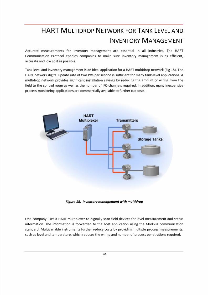
Accurate measurements for inventory management are essential in all industries. The HART Communication Protocol enables companies to make sure inventory management is as efficient,
accurate and low cost as possible.
Tank level and inventory management is an ideal application for a HART multidrop network (Fig 18). The
HART network digital update rate of two PVs per second is sufficient for many tank‐level applications. A
multidrop network provides significant installation savings by reducing the amount of wiring from the
field to the control room as well as the number of I/O channels required. In addition, many inexpensive
process‐monitoring applications are commercially available to further cut costs.
Figure 18. Inventory management with multidrop
One company uses a HART multiplexer to digitally scan field devices for level‐measurement and status
information. The information is forwarded to the host application using the Modbus communication
standard. Multivariable instruments further reduce costs by providing multiple process measurements,
such as level and temperature, which reduces the wiring and number of process penetrations required.
52

7/28/2019 HART Guide
http://slidepdf.com/reader/full/hart-guide 53/174
MULTIDROP FOR TANK FARM MONITORING
In one tank farm application, 84 settlement tanks and filter beds on a very large site (over 300,000 m2)
are monitored using HART multidrop networks and HART RTUs (see SCADA/RTU Systems). The HART
architecture required just eight cable runs for 84 tanks, with 10‐11 devices per run (Fig 19). Over 70 individual runs of over 500m each were eliminated. Cable savings were estimated at over $40,000 (USD)
when compared to a conventional installation. RTU I/O was also reduced, which resulted in additional
hardware and installation savings. The total installed cost was approximately 50% of a traditional 4‐20
mA installation.
Figure 19. Tank farm monitoring with multidrop
53
7/28/2019 HART Guide
http://slidepdf.com/reader/full/hart-guide 54/174
UNDERGROUND PETROLEUM STORAGE WITH HART
COMMUNICATION FOR ACCURACY
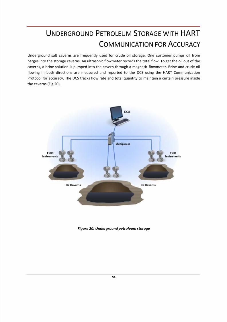
Underground salt caverns are frequently used for crude oil storage. One customer pumps oil from
barges into the storage caverns. An ultrasonic flowmeter records the total flow. To get the oil out of the
caverns, a brine solution is pumped into the cavern through a magnetic flowmeter. Brine and crude oil
flowing in both directions are measured and reported to the DCS using the HART Communication
Protocol for accuracy. The DCS tracks flow rate and total quantity to maintain a certain pressure inside
the caverns (Fig 20).
Figure 20. Underground petroleum storage
54
7/28/2019 HART Guide
http://slidepdf.com/reader/full/hart-guide 55/174
LONZA CHOOSES HART TECHNOLOGY FOR
Q UICK VALIDATION AND COMMISSIONING
PROJECT OBJECTIVES
• Assure quality data communications in processing specialty pharmaceutical and biotech
chemicals
SOLUTION
• Used for both distrubuted control and asset management system applications
• A batch system exclusively using HART‐enabled instrumentation across1,700 I/O points
• Another DCS system hosts 1,400 HART devices with 7000 I/O points
• RESULTS
• HART Communication halves field device commissioning time, “pays for itself’ through auto‐
generation of validation documentation
• HART technology supports Lonza’s continued adherence to current Good Manufacturing
Practices
World biotech pharmaceutical leader taps HART Communication at new batch and continuous plants for
the technology’s reliability and quick cost ‐ justification
Lonza, headquartered in Basel, Switzerland, is one of the world's leading suppliers to the
pharmaceutical, healthcare and life science industries. The chemical processor has a specialty in high‐
quality biotech products, which are manufactured at its largest processing and research and
development facility in Visp, Switzerland. Among its challenges, the site, with 2,600 employees, must
assure quality in the microbial fermentation of active, intermediate ingredients such as vitamin B3 or
niacin, of which Lonza supplies roughly 75 percent of the world’s demand.
55
7/28/2019 HART Guide
http://slidepdf.com/reader/full/hart-guide 56/174
Multi‐product plants
To support current Good Manufacturing Practices (GMP) in its Small Scale Biotech Manufacturing facility
(BPMSS) commissioned in 2004, Lonza chose HART technology for data communications between
process instrumentation and the distributed control system (DCS), including the plant’s first plant asset
management system. This system, integrated with its process control system, spans more than 1,700 I/O
for measuring temperature, pressure, flow, level and various analytical parameters.
HART Tech’s Speed, Validation Documentation Justifies Cost
The BPMSS employs 67, in two areas, microbial fermentation in one building and a purification process
housed in a new building. The facility, which uses solvents in fermentation and purification zones, is
designed to hazardous‐area standards.
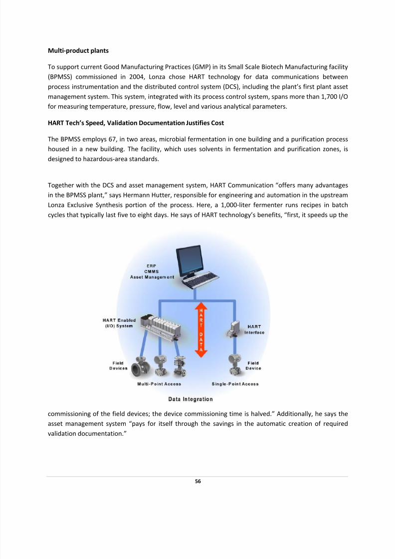
Together with the DCS and asset management system, HART Communication “offers many advantages
in the BPMSS plant,” says Hermann Hutter, responsible for engineering and automation in the upstream
Lonza Exclusive Synthesis portion of the process. Here, a 1,000‐liter fermenter runs recipes in batch
cycles that typically last five to eight days. He says of HART technology’s benefits, “first, it speeds up the
commissioning of the field devices; the device commissioning time is halved.” Additionally, he says the
asset management system “pays for itself through the savings in the automatic creation of required
validation documentation.”
56

7/28/2019 HART Guide
http://slidepdf.com/reader/full/hart-guide 57/174
HART technology is a standard off ‐the‐shelf option from all the major instrumentation suppliers Lonza
uses; the company uses only HART technology‐equipped field devices.
New, Larger Plant Also Uses HART Technology
Following success in its batch operations, Lonza chose HART technology as a solution in a new, larger
Biotech Pharmaceutical plant housing two 15,000‐Liter fermentation units — that’s 30 times the
production capacity of the BPMSS facility.
The new facility employs an estimated staff of 150 and boasts a considerable process automation
network of more than 7000 I/O points and 1,400 HART‐enabled field devices communicating across 55
DCS controllers, five servers, 30 operator stations and 60 human‐machine interface stations.
Even as engineers were evaluating the extent to which it will use Foundation fieldbus, Hutter says, “we
have again decided for the HART technology, because the low risk of installing, which guarantees an in‐
time plant start‐up and offers a larger catalog of instruments.”
2005 HART Plant of the Year ‐ FINALIST
57
7/28/2019 HART Guide
http://slidepdf.com/reader/full/hart-guide 58/174
GENENTECH USES HART TECHNOLOGY TO REDUCE
LIFE CYCLE DEVICE MANAGEMENT, INSTALLATION AND
START‐UP COSTS
PROJECT OBJECTIVES
• Reduce installation costs and startup risks during construction of new biotechnology facility
• Manage critical device configurations that have a direct impact on plant efficiency and product
quality
• Reduce lifecycle device management costs
SOLUTION
• Integrate HART Communication with distributed control system (DCS)
• Install HART‐enabled instrumentation and products throughout facility
RESULTS
• Mitigated risks
• Eliminated addressing, network‐sizing, special communication requirements
• No learning curve
• Enhanced view of instruments
• Remote device setup and configuration
•
Online configuration‐management database
• Regulatory compliance protection
Biotechnology manufacturer Genentech Inc. (San Francisco) is integrating HART Communication with the
distributed control system (DCS) in its CCP2 facility in Vacaville, California, to manage critical device
configurations that have a direct impact on plant efficiency and product quality. Genentech chose HART
technology because of its cost ‐effectiveness, availability, reliability, ease‐of ‐use and flexibility.
58
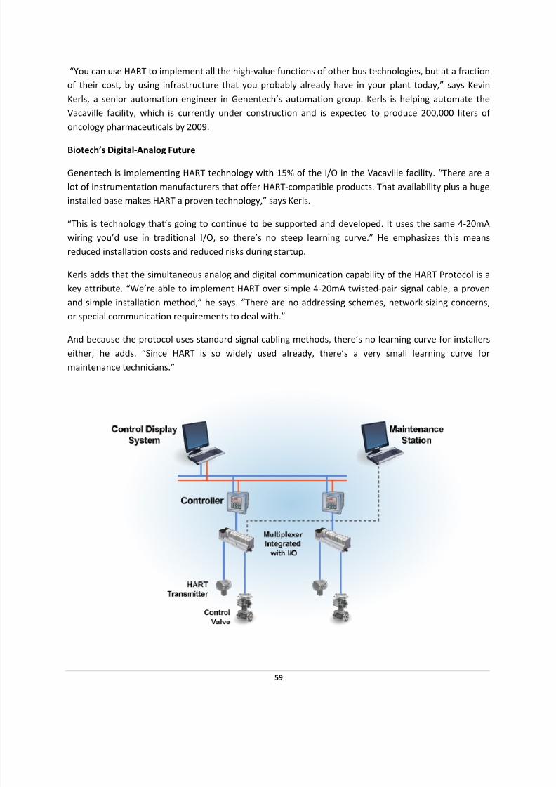
7/28/2019 HART Guide
http://slidepdf.com/reader/full/hart-guide 59/174
“You can use HART to implement all the high‐value functions of other bus technologies, but at a fraction
of their cost, by using infrastructure that you probably already have in your plant today,” says Kevin
Kerls, a senior automation engineer in Genentech’s automation group. Kerls is helping automate the
Vacaville facility, which is currently under construction and is expected to produce 200,000 liters of
oncology pharmaceuticals by 2009.
Biotech’s Digital‐Analog Future
Genentech is implementing HART technology with 15% of the I/O in the Vacaville facility. “There are a
lot of instrumentation manufacturers that offer HART‐compatible products. That availability plus a huge
installed base makes HART a proven technology,” says Kerls.
“This is technology that’s going to continue to be supported and developed. It uses the same 4‐20mA
wiring you’d use in traditional I/O, so there’s no steep learning curve.” He emphasizes this means
reduced installation costs and reduced risks during startup.
Kerls adds that the simultaneous analog and digital communication capability of the HART Protocol is a key attribute. “We’re able to implement HART over simple 4‐20mA twisted‐pair signal cable, a proven
and simple installation method,” he says. “There are no addressing schemes, network‐sizing concerns,
or special communication requirements to deal with.”
And because the protocol uses standard signal cabling methods, there’s no learning curve for installers
either, he adds. “Since HART is so widely used already, there’s a very small learning curve for
maintenance technicians.”
59
7/28/2019 HART Guide
http://slidepdf.com/reader/full/hart-guide 60/174
Genentech reports it also chose HART Communication because its installed instruments are HART‐
enabled. “So, we need no new infrastructure other than a new database server. The information is
seamlessly integrated throughout the I/O, the DCS controller, and the process data server,” Kerls says. In
other systems, however, he believes multiplexers or other devices are needed to pick up digital signals.
“With our system, HART data is tightly integrated so that information is available right in the DCS.”
Kerls adds it’s important that Genentech can use any vendor’s flow or temperature devices as long as
they’re HART‐compatible. “If a device that we wanted had a HART option, we asked for it. For almost all
devices, the HART capability was free from the vendor. But even if the HART option cost money, we still
purchased it,” he recalls.
Remote Configuration Nearby
The ability to view instrument health and other monitoring parameters is available in Genentech’s DCS
without implementing added hardware.
“We’re able to view/modify instrument configurations without interrupting process monitoring,” Kerls explains. Genentech chose HART Communication because other buses had design issues, which are
different from HART and its 4‐20mA capability. “So it takes more time to get other buses operable. We
really felt that we get the majority of the benefit via HART,” he adds.
Number one on Kerls’ list of HART benefits is an enhanced view of the instruments. “This includes
status, alarming information, and remote configuration.”
Genentech also values the remote capabilities of HART technology. “The biggest bang for the buck is
remote configuration and remote monitoring. HART won out over all the other buses,” Kerls asserts.
“Because HART provides remote capabilities, installation simplicity, and met our requirements, it easily
beat the other buses.”
Remote device setup and configuration is essential because it allows Genentech to easily backup
instrument configurations using a central database. The firm also can make changes to instrument
configurations from a controlled database compliant with 21 CFR Part 11—Title 21 Code of U.S. Federal
Regulations Part 11: Electronic Records; Electronic Signatures from the U.S. Food and Drug
Administration. Kerls says this was possible without relying on handheld devices or a technician’s
handwritten notes.
Overall Configuration Crucial
Central configuration management is another area where Genentech will use the HART protocol in their
new facility. The company will use a database to capture, view, verify, test, and backup instrument
configurations for more than 1,125 instruments during the startup of CCP2.
“The HART protocol with its online configuration‐management database eliminates the need for a time‐
consuming paper process,” says Kerls. “It probably saves an hour off each calibration which basically is a
60

7/28/2019 HART Guide
http://slidepdf.com/reader/full/hart-guide 61/174
61
half a person‐year saved under normal operations. In initial documentation of parameters and startup,
this may also save 3,000 hours. These are very conservative estimates.”
Compared to traditional I/O, Genentech can use HART Communication to diagnose an instrument just by
opening a view, rather than sending someone out to the device’s location. “If anything goes wrong with
that device, it’ll notify the operator though a DCS alarm,” he adds.
Genentech reports that HART‐associated work at CCP2 is enabling more efficient management of
instrument configuration. “Once we get this up and running, part of corporate automation engineering’s
role is to disseminate information about the project throughout the corporation,” says Kerls “This also
means educating our maintenance group on our systems’ capabilities and developing efficient processes
to leverage HART‐enabled technology.”
Another benefit provided by HART technology at this facility includes building the corporation’s
instrument configuration‐and‐calibration Standard Operating Procedures (SOP) on how to use the
protocol and Genentech’s configuration management database.
local automation engineering group—to use them, then the corporation never
gets the full benefit.”
“We’ll continue to minimize the time required to perform configurations and calibrations,” Kerls
emphasizes. “You can put these technologies in, but if you aren’t educating your lifecycle group—
maintenance and the
7/28/2019 HART Guide
http://slidepdf.com/reader/full/hart-guide 62/174
Benefits may be limited by not partnering with maintenance and local automation engineering on the
front and back ends of a project. “You may provide a solution based on incorrect assumptions and it
may not meet their business criteria,” says Kerls. “And, if you don’t partner with them on the back end
of the project, the SOPs won’t be developed with HART technology in mind.”
Compliance Protects
Doses
Diagnostics. Maintenance. Regulatory compliance. SOPs exist for them. All are taken seriously at CCP2,
and HART technology plays a crucial role here, too.
“Our HART devices are installed as part of an 8,500‐I/O DCS. Any device errors or alarms will
automatically be available to the operators/technicians,” explains Kerls. HART Communication allows
Genentech’s staff to receive device‐specific alarm values, which reduces troubleshooting time, though
they don’t know how much yet.
“On a new plant, we don’t really know what the issues will be,” Kerls says. “But we expect that we’ll find
them quicker.” Faster problem identification goes directly to the bottom line.
In addition, the HART protocol helps CCP2’s service department minimize the time required for
troubleshooting and calibrations. This is because all configuration parameters historically were noted by
hand and often were misplaced, lost, or simply incorrect, Kerls adds. “Our HART implementation will
ensure that the current configuration is always correctly backed up.”
And, if an instrument needs replacement, HART also simplifies this process. “We simply need to
download the backed up configuration for the old instrument from our HART configuration
management database. These configuration parameters then upload to the new device directly through
the analog I/O card without special connections,” says Kerls. “Being able to effectively manage our
instrument configurations reduces our regulatory risk and our risk to product.”
Risk to product involves reduced efficiency, which usually means producing less and producing poorer
quality. “If a critical instrument is involved and you can’t prove you had adequate control over properly
configured devices, it could lead to regulatory action and/or a recall of the entire batch,” says Kerls.
“More than likely, however, you’d have offline analytical measurements to monitor the batch so you
might not lose the batch, but you might spend a lot of time defending it.”
Overall, Kerls is even more optimistic about the role of HART technology in Genentech’s future. “If HART
works well at CCP2, we can just roll it out to other Genentech plants,” he says. “If you use HART, you’re
going
to
save
big
time
in
lifecycle
device
management
because
the
installation
cost
is
no
more
than
if
we
installed traditional I/O systems.”
62
7/28/2019 HART Guide
http://slidepdf.com/reader/full/hart-guide 63/174
DUPONT USES HART DATA TO SATISFY
SAFETY INTERLOCK SYSTEM VALVE TEST
REQUIREMENTS
PROJECT OBJECTIVES
• Needed a better way to test safety interlock control valves during plant operations.
SOLUTION
• DuPont added intermediate instrumentation to extract relevant data from the plant's HART
instruments, and Moore Industries' SPA HART loop monitor and alarm is used for this purpose
• Use partial valve‐stroke testing of emergency shutdown valves during normal operations for
fewer and shorter shutdowns.
• HART data is superimposed on the 4‐20mA connection, and the SPA loop monitor and alarm
extracts the valve‐stem position from the HART data. The SPA then sends the actual valve‐stem
position data to the DCS via an additional 4‐20mA connection.
• Over 100 control valves equipped with Moore SPA loop monitors were installed, so valve safety
interlock testing would be a less labor‐intensive and cumbersome operation
RESULTS
• Expedites testing of safety interlock valves, shortening plant shutdowns
• Provides fail‐safe inputs to the hard‐wired relay safety interlock system
• Allows remote configuration and ranging of virtually all instrumentation
• Reduces number / duration of shutdowns by using partial valve‐stroke testing
• Establishes the foundation for an asset management system
"Virtually all of the plant instrumentation is HART ‐enabled...temperature, pressure, level, and flow."
63

7/28/2019 HART Guide
http://slidepdf.com/reader/full/hart-guide 64/174
64
The DuPont DeLisle titanium dioxide manufacturing facility in Pass Christian, Mississippi, uses HART
Communication full‐time in daily operations even though it does not have a HART‐enabled control
system. The plant is migrating to using HART data for additional cost‐effective solutions that will deliver
significant benefits to the enterprise today and
into the future.
The DeLisle plant produces DuPont's proprietary
R‐104 Ti‐Pure titanium dioxide (TiO2). TiO2 is a
white pigment used in paint, plastics, and
products where color retention is desired. TiO2
absorbs ultra‐violet light energy and it also
possesses light‐scattering properties that
enhance whiteness, brightness, and opacity.
TiO2 production requires a sophisticated
manufacturing process that includes chemical
reduction, purification, precipitation, washing,
and chlorination of titanium, iron, and other metal sulfates. "DuPont determined that the best way to
control and monitor these processes was with HART‐enabled instrumentation," says Joe Moffett, project
manager with DuPont. "Virtually all of the plant instrumentation is HART‐enabled, and this includes
instruments used to monitor and control temperature, pressure, level, and flow."
TheDeLisle plant control and instrumentation system uses the HART Communication Protocol in a
variety of ways. HART data is used as an input to the safety interlock system and as an input to the
control system. Like most other users, DeLisle personnel use handheld HART communicators for
configuration, calibration, and troubleshooting. And as we'll see, future plans call for HART data as a key
input to an asset management system.
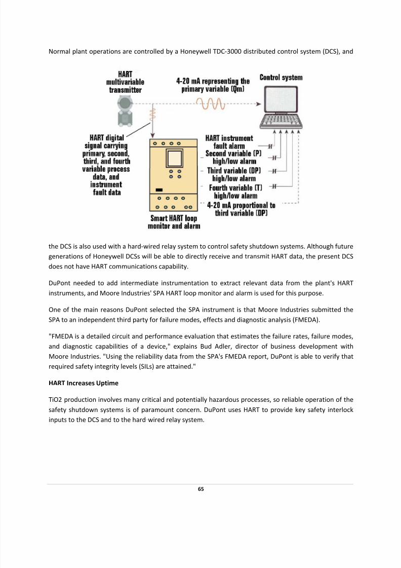
7/28/2019 HART Guide
http://slidepdf.com/reader/full/hart-guide 65/174
Normal plant operations are controlled by a Honeywell TDC‐3000 distributed control system (DCS), and
the DCS is also used with a hard‐wired relay system to control safety shutdown systems. Although future
generations of Honeywell DCSs will be able to directly receive and transmit HART data, the present DCS
does not have HART communications capability.
DuPont needed to add intermediate instrumentation to extract relevant data from the plant's HART
instruments, and Moore Industries' SPA HART loop monitor and alarm is used for this purpose.
One of the main reasons DuPont selected the SPA instrument is that Moore Industries submitted the
SPA to an independent third party for failure modes, effects and diagnostic analysis (FMEDA).
"FMEDA is a detailed circuit and performance evaluation that estimates the failure rates, failure modes,
and diagnostic capabilities of a device," explains Bud Adler, director of business development with
Moore Industries. "Using the reliability data from the SPA's FMEDA report, DuPont is able to verify that
required safety integrity levels (SILs) are attained."
HART Increases Uptime
TiO2 production involves many critical and potentially hazardous processes, so reliable operation of the
safety shutdown systems is of paramount concern. DuPont uses HART to provide key safety interlock
inputs to the DCS and to the hard‐wired relay system.
65

7/28/2019 HART Guide
http://slidepdf.com/reader/full/hart-guide 66/174

7/28/2019 HART Guide
http://slidepdf.com/reader/full/hart-guide 67/174
operation. The technician would have to observe valve travel, and communicate this information to
control room personnel.
"There are over 100 control valves equipped with Moore SPA loop monitors, so valve safety interlock
testing would be a labor‐intensive and cumbersome operation without HART Communication," observes
Moffett.
Online Tests Reduce Outages
DuPont has plans to take valve testing to another level‐a level that will reduce the number and lengths
of outages required for safety interlock testing. Certain valve testing requirements for safety interlock
systems can be met with partial valve‐stroke testing of emergency shutdown valves during normal
operations. Performing those tests during normal operations means fewer shutdowns are required, and
the required tests take less time so the shutdowns can be shorter.
14
CRITICAL INTERLOCK AUTOMATED TESTING
SAFETY INTERLOCKSYSTEM
SIS
REGULATORY
CONTROL SYSTEM
HART INTERFACE
HART Enabled¾ Simulate interlock value
¾ Bump valve
¾ Verify valve movement
¾ Issue report
ENGINEERINGCONSOLE
OPERATOR CONSOLE
Partial valve‐stroke testing during normal operations is a procedure, either manual or automated, used
to stroke a valve over a small percentage of the valve's total travel range. For example, a safety interlock
valve might be fully closed during normal operations. Partial valve‐stroke testing could be used to move
67
7/28/2019 HART Guide
http://slidepdf.com/reader/full/hart-guide 68/174
the valve to a slightly open position. This would verify valve operation without affecting normal
operations.
The present system could be used to undertake manual partial valve‐stroke testing, or an upgraded
system could be used to implement automated partial valve‐stroke testing.
"We are currently evaluating device management system that would be able to directly accept data
from all of our HART instruments," Moffett says, "and the system could be used to implement
automated partial valve‐stroke testing."
Other plans call for using additional SPA capabilities to monitor the diagnostic status of the valve‐stem
positioners, to provide alarm on low valve‐operating air pressure, and to provide relay contacts for open
and closed valve position. For more critical applications, one‐out‐of ‐two (1oo2) and two‐out‐of ‐three
(2oo3) configurations can be used to increase availability and reliability.
Fail‐Safe System Relies on HART Communication
Most safety interlocking at the DeLisle plant is implemented through a dedicated DCS controller, but
certain processes must be equipped with a hard‐wired relay safety shutdown system. Many of these
processes use HART‐enabled pressure and temperature transmitters. Each of these transmitters sends a
4‐20mA process variable signal to a Moore Industries SPA loop monitor that decodes the HART data
superimposed on the 4‐20mA signal.
The SPA then sends a process variable signal derived from the HART data to the DCS, and it also sends
fail‐safe alarm contacts to the hard‐wired relay safety shutdown system. These alarm contacts are set to
indicate high‐level, low‐level, and the presence or absence of the HART signal.
HART‐enabled instruments allow DuPont to operate the plant in a safe and efficient manner. "HART and the SPAs provide a solution that unlocks a wealth of diagnostic and process information in the
positioners and transmitters," says DuPont project manager Joe Moffett. "This information is used to
increase reliability and minimize the duration of required plant shutdowns."
DuPont is using this highly efficient TiO2 processing site as a benchmark for other facilities because of its
outstanding compliance with safety, health, and environmental requirements. DuPont plans to fully
exploit the available HART data with an asset management system that will provide automated partial
valve‐stroke testing, predictive maintenance alerts, and comprehensive management of the plant
instrumentation system.
Major Benefits
of
HART
Communication
for
DuPont
• Expedites testing of safety interlock valves, shortening plant shutdowns
• Provides fail‐safe inputs to the hard‐wired relay safety interlock system
• Allows remote configuration and ranging of virtually all instrumentation
68

7/28/2019 HART Guide
http://slidepdf.com/reader/full/hart-guide 69/174
• Reduces number / duration of shutdowns by using partial valve‐stroke testing
• Establishes the foundation for an asset management system
2002 HART Plant of the Year
69
7/28/2019 HART Guide
http://slidepdf.com/reader/full/hart-guide 70/174
EASTMAN CHEMICAL USES HART PRESSURE
TRANSMITTER TO REDUCE SPIKES AND ACHIEVE COST‐
EFFECTIVE MAINTENANCE
PROJECT OBJECTIVES
• During process upsets, tank pressure exceeded range of analog pressure transmitters
SOLUTION
• Installation of a single HART‐enabled transmitter, replacing two analog transmitters
RESULTS
• HART Communication lets the transmitter read actual voltage to determine actual pressure
without re‐spanning the transmitter and introducing error
• Upsets that exceed expected range can be accurately measured by the digital HART
Communication signal.
• Remote configuration saves time by reducing trips to the field
One HART ‐enabled transmitter replaces two analog transmitters to cope with pressure spikes and offer
more cost ‐effective maintenance
At Eastman Chemical Co.’s operation in Longview, Tex., pressurized tanks may have an allowable
working pressure of 63 psig, which may be 10 times more than the span of the tanks’ pressure
transmitters. According to Josh Lowery, electrical engineer at Eastman Chemical, pressure variations in
those tanks can cause problems.
On startup, one tank’s pressure shot up and popped a relief valve. “The tank shot up past 12 psig,” says
Lowery, who adds that the tank’s pressure transmitter span is 0‐12 psig. A solution using HART
technology includes only one transmitter, rather than two as required before.
70
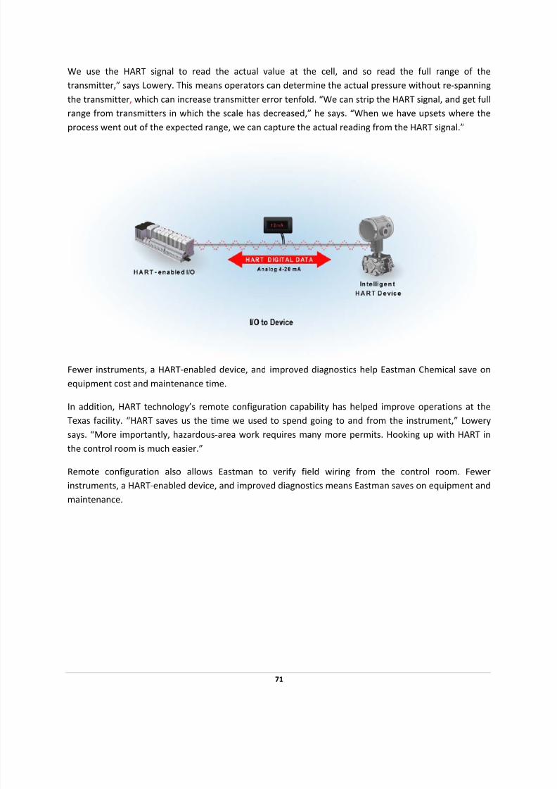
7/28/2019 HART Guide
http://slidepdf.com/reader/full/hart-guide 71/174
We use the HART signal to read the actual value at the cell, and so read the full range of the
transmitter,” says Lowery. This means operators can determine the actual pressure without re‐spanning
the transmitter, which can increase transmitter error tenfold. “We can strip the HART signal, and get full
range from transmitters in which the scale has decreased,” he says. “When we have upsets where the
process went out of the expected range, we can capture the actual reading from the HART signal.”
Fewer instruments, a HART‐enabled device, and improved diagnostics help Eastman Chemical save on
equipment cost and maintenance time.
In addition, HART technology’s remote configuration capability has helped improve operations at the
Texas facility. “HART saves us the time we used to spend going to and from the instrument,” Lowery
says. “More importantly, hazardous‐area work requires many more permits. Hooking up with HART in
the control room is much easier.”
Remote configuration also allows Eastman to verify field wiring from the control room. Fewer
instruments, a HART‐enabled device, and improved diagnostics means Eastman saves on equipment and
maintenance.
71

7/28/2019 HART Guide
http://slidepdf.com/reader/full/hart-guide 72/174

7/28/2019 HART Guide
http://slidepdf.com/reader/full/hart-guide 73/174
Handed the task of overseeing the implementation of communication and control systems that would
serve as the automation data lifeline for two new plants, Sasol Solvents engineers started small, but
finished big. The plants, to be constructed by South Africa's Sasol Solvents and Olefins and Surfactants,
housed some 10,000 I/O points. A major installation of HART‐capable intelligent devices led to big
savings by using HART technology already in the company's chemical plants.
Johan Claassen, engineering manager for control systems, instrumentation, and electrical, began with a
vision to implement a control system and corresponding field instrumentation that had the intelligence
to predict failures before downtime resulted. This initial vision ultimately led to estimated yearly savings
of 6.5 million South African Rand (US $1 million).
"We significantly exceeded my expectations. I was expecting two or three million Rand in savings," he
says. However, Claassen believes this figure to be conservative, as a number of benefits are hard or
impossible to quantify.
Claassen's and Sasol's results benchmark what's achievable, according to Ron Helson, Executive Director
of the HART Communication Foundation. "They really stepped out of the box and set the example for
what is possible when you start using the full potential of smart instrumentation," he says.
To finish this big, however, Claassen faced numerous obstacles that had him battling balky technology
and overcoming objections from sometimes skeptical management.
73

7/28/2019 HART Guide
http://slidepdf.com/reader/full/hart-guide 74/174
Breaking new ground
In 2000, Claassen dusted off his crystal ball and peered into the future. He didn't do this because of the
new millennium. Rather, he went into the forecasting business because Sasol, an integrated oil‐and‐gas
company with substantial chemical interests, needed to expand.
In response to that need, Sasol would, over the next few years, build a butanol plant capable of
producing 150,000 metric tons a year of solvent for the company's customers in the paint and ink
industries. The company would also construct an acrylic acid and acrylates project that would eventually
supply about 125,000 tons of products. Because of these projects, two plants would arise from empty
fields near the company's complex in Sasolburg, a town midway between Cape Town and Johannesburg,
where Sasol had gotten its start 50 years earlier.
Claassen, who'd joined the company in 1995 with a control‐system engineering degree from the
University of Pretoria, focused on the automation and control systems proposed for the new facilities.
He had his own plans for these systems, although he didn't have much of a team to help him push his
ideas.
"The team consisted of two people—myself and a Sasol technology engineer—with the vision to
implement a control system and field instrumentation that had the intelligence to predict failures before
they caused plant downtime," he recalls. The group started looking for solutions, investigating various
technology options. It also looked at different distributed control systems (DCS) to provide needed
functions.
But Claassen could not start from a blank slate. The automation and control systems for the new plants
had to take into account Sasol's existing relationships and installed technology. On that basis, HART‐
based instruments and HART I/O had an advantage. Sasol already had a limited installation of HART instruments and systems in other sites within Sasol's Solvents group. In addition, Claassen notes that the
communications protocol offered another benefit.
"HART had the advantages of normal 4‐20mA where you have one pair of wires per field device. Sasol's
design specifications for the new plants were built around this," he says.
Finding success
Changing to another industrial communication protocol would have forced the company to update
design specifications before building new facilities. But Claassen was prepared to go down that road
because he felt that new technologies had to be part of the new facilities.
74
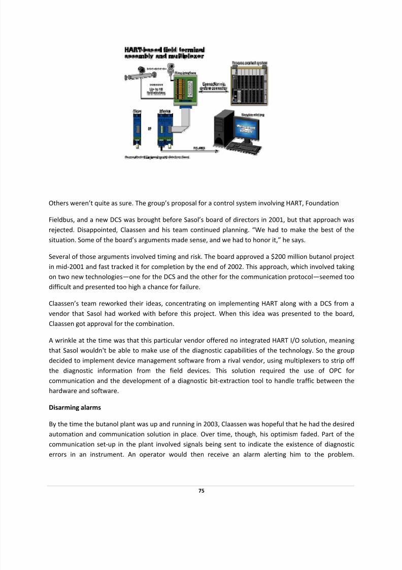
7/28/2019 HART Guide
http://slidepdf.com/reader/full/hart-guide 75/174
Others weren’t quite as sure. The group’s proposal for a control system involving HART, Foundation
Fieldbus, and a new DCS was brought before Sasol’s board of directors in 2001, but that approach was
rejected. Disappointed, Claassen and his team continued planning. “We had to make the best of the
situation. Some of the board’s arguments made sense, and we had to honor it,” he says.
Several of those arguments involved timing and risk. The board approved a $200 million butanol project
in mid‐2001 and fast tracked it for completion by the end of 2002. This approach, which involved taking
on two new technologies—one for the DCS and the other for the communication protocol—seemed too
difficult and presented too high a chance for failure.
Claassen’s team reworked their ideas, concentrating on implementing HART along with a DCS from a
vendor that Sasol had worked with before this project. When this idea was presented to the board,
Claassen got approval for the combination.
A wrinkle at the time was that this particular vendor offered no integrated HART I/O solution, meaning
that Sasol wouldn't be able to make use of the diagnostic capabilities of the technology. So the group
decided to implement device management software from a rival vendor, using multiplexers to strip off
the diagnostic information from the field devices. This solution required the use of OPC for
communication and the development of a diagnostic bit‐extraction tool to handle traffic between the
hardware and software.
Disarming alarms
By the time the butanol plant was up and running in 2003, Claassen was hopeful that he had the desired
automation and communication solution in place. Over time, though, his optimism faded. Part of the
communication set‐up in the plant involved signals being sent to indicate the existence of diagnostic
errors in an instrument. An operator would then receive an alarm alerting him to the problem.
75

7/28/2019 HART Guide
http://slidepdf.com/reader/full/hart-guide 76/174
Unfortunately, operators and engineers were getting 10 alerts a minute, and many weren't about
anything an operator could affect. Consequently, those alarms were largely ignored.
Due to this alarm situation, the Sasol team switched its approach in 2004, implementing a solution that
used the same vendor for both hardware and software. The company also embarked on an alarm
management program and changed its philosophy on maintenance‐related alarms, meaning that operators were only presented with those alarms they could do something about. Claassen reports that,
today, the number of alarms seen by operators has been cut by more than a factor of 10, and that's only
the beginning of the upgrades.
"As things improve, we will start training the operators to do first‐line fault finding on our asset
management software as well," he says.
The change in alarm philosophy coincided with the completion of the acrylic acid and acrylates facility
and completion of current building projects. At present, Sasol uses some 4,000 HART instruments and
about 400 FOUNDATION fieldbus devices.
76
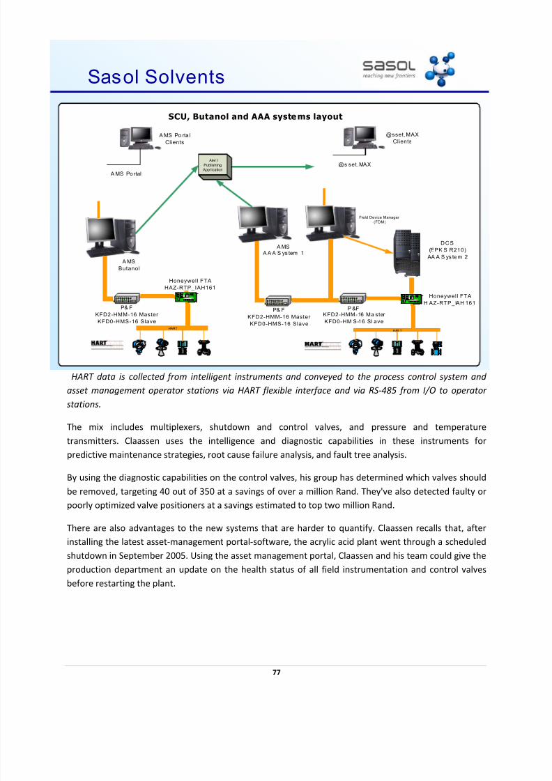
7/28/2019 HART Guide
http://slidepdf.com/reader/full/hart-guide 77/174
77
HART data is collected from intelligent instruments and conveyed to the process control system and
asset management operator stations via HART flexible interface and via RS‐485 from I/O to operator
stations.
The mix includes multiplexers, shutdown and control valves, and pressure and temperature
transmitters. Claassen uses the intelligence and diagnostic capabilities in these instruments for
predictive maintenance strategies, root cause failure analysis, and fault tree analysis.
By using the diagnostic capabilities on the control valves, his group has determined which valves should
be removed, targeting 40 out of 350 at a savings of over a million Rand. They've also detected faulty or
poorly optimized valve positioners at a savings estimated to top two million Rand.
There are also advantages to the new systems that are harder to quantify. Claassen recalls that, after
installing the latest asset‐management portal‐software, the acrylic acid plant went through a scheduled
shutdown in September 2005. Using the asset management portal, Claassen and his team could give the
production department an update on the health status of all field instrumentation and control valves
before restarting the plant.
20
Sasol Solvents
HAR T
Field Device Manager
(FDM)
HART
A MS
Butanol
@s set.MAX
A MS Po rtal
@sset.MAXClients
A MS Po rta l
Clients
Aler t
Publishing
App lication
SCU, Butanol and AAA systems layout
A MS A A A S ys tem 1
DCS
(EPK S R210)
AA A S ys te m 2
Honeywell FTA
H AZ-RTP_IAH 161
Honeywell FTA
HAZ-RTP_IAH161
P &FKFD2-HMM-16 Ma ster
KFD0-HM S-16 Sl ave
P& F
KFD2-HMM-16 Master
KFD0-HMS-16 Slave
P& F
KFD2-HMM-16 Master
KFD0-HMS-16 Slave

7/28/2019 HART Guide
http://slidepdf.com/reader/full/hart-guide 78/174
This was not possible before because it was not easy to tell how well quality‐assurance and quality‐
control tasks were done during the shutdown. Thanks to the new technology, Claassen was able to
provide an answer much quicker than before.
"In less than five minutes I could give my production department the go‐ahead to start up the plant.
Before we had HART and the new software packages, it was very difficult to do this. You had to rely on the information that your people could give you," he says.
Results obtained through the use of intelligent instruments have been so encouraging to this point that
Sasol plans to deploy similar systems in the company's other plants over the next few years.
2005 HART
Plant
of
the
Year
78
7/28/2019 HART Guide
http://slidepdf.com/reader/full/hart-guide 79/174
ORBCOMM GLOBAL USES HART COMMUNICATION IN
SATELLITES TO TRANSFER DATA
PROJECT OBJECTIVES
• Find a low‐cost communications solution for satellite transceivers sourced from multiple
manufacturers
SOLUTION
• HART technology equipped the full 28‐satellite network for remote asset monitoring
applications
• Provide a method for customers to transmit critical data from offshore pipelines, remote well
heads, tanks or flowmeters
RESULTS
• Critical data easily, efficiently transmitted from the field to 500 miles ‘up,’ via Internet or file
transfer
• Rapid, fully‐configurable data transfers and remote diagnostics for a wide variety of applications
in the upstream oil and gas market
ORBCOMM Global,
the
first
low
‐Earth
orbit
(LEO)
satellite
provider
of
data
communications
services,
helps its customers transmit wellhead pressures, natural gas production and tank levels
It’s official. HART Communication is “out of this world.” Since 1999, ORBCOMM Global has successfully
used the HART Protocol to transfer data from HART field devices to low‐Earth orbit (LEO) satellites. Still
flying high today, ORBCOMM’s Controlsat FieldSentry RTU continues to support two‐way message traffic
with HART‐enabled field devices through the company’s satellite network.
“ORBCOMM Global became the first commercial LEO provider of data communications services when
we completed our 28‐satellite constellation in September 1998” says Wally Walter, Controlsat product
manager. “The network was designed to be a low‐cost communications solution with typical messaging
fees between 10 and 50 dollars a month (circa 1999) and affordable satellite transceivers available from
five major manufacturers.”
79
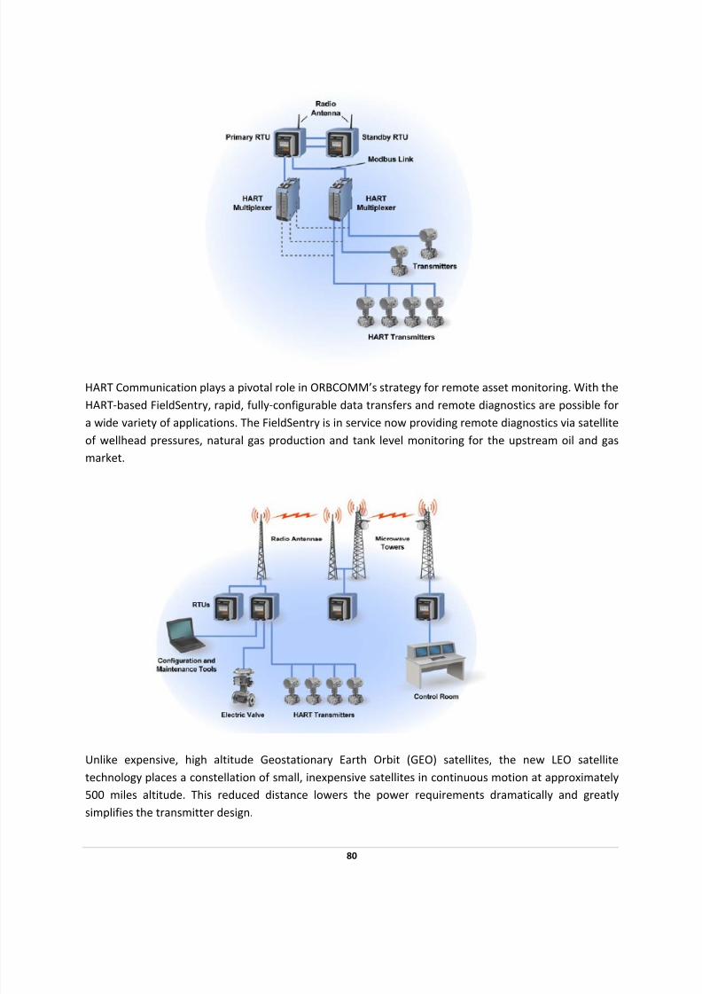
7/28/2019 HART Guide
http://slidepdf.com/reader/full/hart-guide 80/174
80
HART Communication plays a pivotal role in ORBCOMM’s strategy for remote asset monitoring. With the
HART‐based FieldSentry, rapid, fully‐configurable data transfers and remote diagnostics are possible for
a wide variety of applications. The FieldSentry is in service now providing remote diagnostics via satellite
of wellhead pressures, natural gas production and tank level monitoring for the upstream oil and gas
market.
Unlike expensive, high altitude Geostationary Earth Orbit (GEO) satellites, the new LEO satellite
technology places a constellation of small, inexpensive satellites in continuous motion at approximately
500 miles altitude. This reduced distance lowers the power requirements dramatically and greatly
simplifies the transmitter design.

7/28/2019 HART Guide
http://slidepdf.com/reader/full/hart-guide 81/174
“This system allows us to transmit critical data from offshore pipelines, remote well heads, tanks or
flowmeters to distant clients via Internet or file transfer,” Walter says.
In this “out of this world” application, the HART Protocol has proven itself once more to be a highly
capable, cost‐saving process management tool. Many new HART‐compatible products, like the
FieldSentry, are making remote operations—data transfers, diagnostics, monitoring and measurements—easy and efficient.
81

7/28/2019 HART Guide
http://slidepdf.com/reader/full/hart-guide 82/174
BP CANADA ENERGY USES HART
COMMUNICATION TO IMPROVE PROCESS
CONTROL AND SAVE MONEY
PROJECT OBJECTIVES
• Achieve accuracy between 0.1 and 0.2 percent in custody transfer of oil as it changes ownership
en route to and from sites across Canada’s oil‐rich Alberta province to meet contractual
requirements
SOLUTION
• In roughly a decade, a majority of the 600 transmitters were upgraded with HART devices and
flow computers handling up to four transmitters each
• HART Communication provided an all‐digital data path, eliminated the need for conversion
when analog‐to‐digital conversions were resulting in metering inaccuracies
• Transmitters were also upgraded for greater accuracy
RESULTS
• HART‐enabled transmitters helped improve accuracy to save almost a quarter‐million dollars
annually
• The plant achieved higher performance using upgraded transmitters and flow computers that
did not require analog step in obtaining measurements
• Marcel Boisvert, senior instrument/electrical craftsman, credits HART Communication with
"fantastic" measurement balances and "phenomenal" accuracies
• Engineers and technicians saved time by reducing trips to the field
Making use of the digital process variable output of HART ‐enabled transmitters, BP Canada Energy
improved its process control and saved substantial time and money.
82
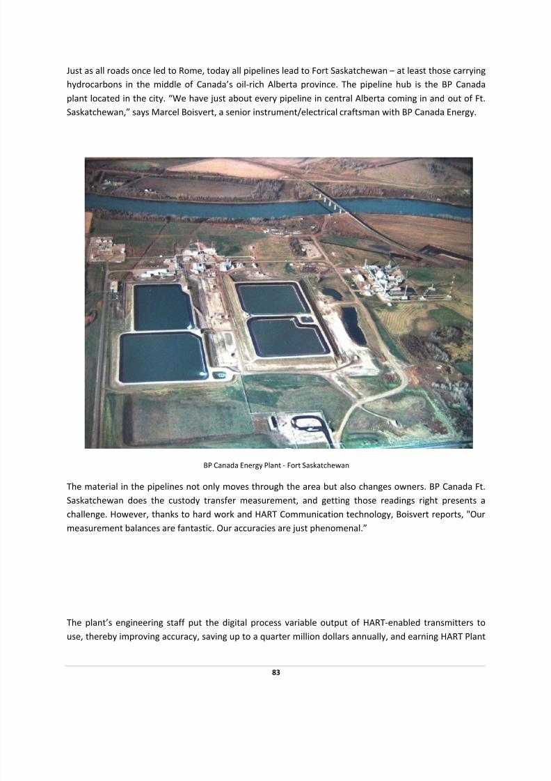
7/28/2019 HART Guide
http://slidepdf.com/reader/full/hart-guide 83/174
Just as all roads once led to Rome, today all pipelines lead to Fort Saskatchewan – at least those carrying
hydrocarbons in the middle of Canada’s oil‐rich Alberta province. The pipeline hub is the BP Canada
plant located in the city. “We have just about every pipeline in central Alberta coming in and out of Ft.
Saskatchewan,” says Marcel Boisvert, a senior instrument/electrical craftsman with BP Canada Energy.
BP Canada Energy Plant ‐ Fort Saskatchewan
The material in the pipelines not only moves through the area but also changes owners. BP Canada Ft.
Saskatchewan does the custody transfer measurement, and getting those readings right presents a
challenge. However, thanks to hard work and HART Communication technology, Boisvert reports, "Our
measurement balances are fantastic. Our accuracies are just phenomenal.”
The plant’s engineering staff put the digital process variable output of HART‐enabled transmitters to
use, thereby improving accuracy, saving up to a quarter million dollars annually, and earning HART Plant
83
7/28/2019 HART Guide
http://slidepdf.com/reader/full/hart-guide 84/174
of the Year honors for 2006. Theirs is a tale interest for anyone who wants to know how HART
technologies can help improve processes.
Balancing the books
The Ft. Saskatchewan plant makes propane, butane, natural gas liquid (NGL) condensate and ethane
with carbon dioxide removed. In a given year, 1.5 million cubic meters of propane leaves the plant,
bound for other BP facilities. The other products produced also ship in large volumes. The plant staff
employs temperature and pressure readings to compensate the flow measurement and quantify what’s
in the pipes.
A decade ago BP Canada started installing HART‐enabled temperature and pressure transmitters in Ft.
Saskatchewan. Today a majority of the 600 transmitters in the plant are HART‐enabled. As part of the
upgrade package, the company also installed flow computers, up to four transmitters per computer.
In the initial configuration, Boisvert says the 4‐20 mA analog signal output from a transmitter was fed
into a flow computer. The digital signal superimposed atop the analog signal as part of the HART standard functioned as a second communication channel to and from the transmitter but was not being
used by the flow computer.
For audit and other purposes, flow‐computer readings were and are compared to that of a standard,
certified gauge. One plant staff person handled transmitter calibration while another did the meter
proving. The accuracy in the mass delivery demanded by contract was one or two tenths of a percent, a
figure that translated into a need for highly accurate temperature and pressure readings.
For example, a temperature error of 0.25 °C results in up to a 0.07% net flow error. Multiplied by the
amount of product Ft. Saskatchewan ships, that error meant a potential loss of $250,000 a year. For
NGL, the corresponding figure was $350,000, creating strong incentives for accurate measurements. In
addition, those receiving the product would make their own readings and take action if a large enough
difference was found. “There will be a correction, if you have somebody at the other end able to do the
measurement as well as you do or better,” says Boisvert in explaining what would happen.
84

7/28/2019 HART Guide
http://slidepdf.com/reader/full/hart-guide 85/174
Speaking one language
Problems, however, cropped up when Boisvert and coworkers tried to reduce the measurement error.
Despite diligent transmitter calibration efforts that should have kept the devices operating within a
tenth degree, meter proving continued to indicate an inaccuracy of up to half a degree. The employee
proving the meter would then adjust the transmitters or ask for them to be calibrated. Calibration
showed that the transmitters were working well within tolerances. The sequence would then repeat for
each employee's area until various team members witnessed each.
The team finally found the problem to be within the flow computer, specifically in the transformation of
the analog signal into its digital equivalent. “The analog to digital conversion was not as accurate as
what we were looking for,” notes Boisvert.
The errors weren’t great, perhaps 0.2 to 0.5 °C on a range of ‐18 to +65.5 °C. On the pressure side, the
discrepancy might be up to 50 kiloPascals on a range of 10,000 kPa. Those small errors, though, were
enough to eat up a significant part of the overall allowable error budget.
Faced with this problem, the team started looking for a solution. A series of tests convinced them the
readout at the transmitter agreed with analog and digital signals. That was when the group decided to
sidestep conversion, notes Boisvert. “If the flow computer speaks HART and the transmitter speaks
HART, let's read the digital value rather than the analog value,” he says, thinking through the process.
85

7/28/2019 HART Guide
http://slidepdf.com/reader/full/hart-guide 86/174
The simple‐sounding idea required a bit of work. For one thing, the flow computer's model didn’t
natively read or write HART commands. However, it was programmable at a low level. The vendor
provided what was essentially a translator, allowing Ft. Saskatchewan’s team to worry only about the
higher level application software.
Part of the solution also involved upgrading the transmitters. A typical specification for a transmitter of 0.5‐degree accuracy wouldn’t work. “We were looking for that 0.2 degree accuracy,” says Boisvert.
Working with vendors, they found transmitters that would hit the more stringent spec. Such a tightening
only made sense, though, because the conversion‐induced error had been eliminated.
Highly accurate results
With transmitters and flow computers talking without an analog step in the middle and with more
accurate transmitters, the Ft. Saskatchewan plant achieved the desired performance. It’s hard to
pinpoint an exact dollar figure saved due to the improvement because, as Boisvert notes, the error could
have been positive or negative. The total amount of the possible adjustment, however, runs in the
hundreds of thousands of dollars a year. Since the setup has been in place for a decade, potential
savings are in the millions of dollars.
Another benefit even harder to quantify has been removal of internal inconsistencies. That has
contributed to creation of a well‐ deserved reputation that helps in certifying measurements to external
parties. “There are never any issues about our accuracy,” says Boisvert.
There’s also been some savings of engineering and technician time. To take one example, the old meter
proving required one employee to take a reading from a certified device placed next to the transmitter.
The staffer would then have to go to where the flow computer was located and see what it measured.
Finally, the employee would have to travel back to the certified instrument and hope there hadn’t been
a process change during this back and forth. Now the task is much easier because the transmitter's
digital display shows what the flow computer sees. “He can look at the certified device sitting right next
to the digital display on the transmitter and compare his readings,” notes Boisvert.
There are also time savings because instruments aren’t being tweaked, and other adjustments aren’t
being made only to be undone later. BP Canada Energy estimates total savings of at least an hour a
week of engineering and technician time.
As for lessons learned by the whole process, Boisvert cites one that could apply to a wide variety of
situations.
“HART
is
not
just
a
maintenance
tool.
It
is
a
process
improvement
tool
as
well,”
he
says.
2006 HART Plant of the Year
86

7/28/2019 HART Guide
http://slidepdf.com/reader/full/hart-guide 87/174
FRENCH NATIONAL RESEARCH INSTITUTE OF AGRONOMY
USES HART COMMUNICATION TO GAINING HIGH
RESOLUTION PROCESS VALUES
PROJECT OBJECTIVES
• Optimize the number of process variables that can be cost‐effectively measured inline
• Obtain an accurate data feed for math modeling of multivariable parameters
SOLUTION
• In addition to direct data measurements, use HART‐enabled multivariable transmitters for
proprietary math models used in real‐time process optimization
RESULTS
• HART Communication‐derived data leads to predictive process models, resists electrical noise
• Wiring and device maintenance require minimal investments
• Measurement quality is “superb, “ accuracy is “excellent“ and the analog path in the
measurement chain is shorter,“ INRA reports.
French agro‐ food researchers use HART technology to create a mathematical model with high resolution
real ‐time HART process values
Researchers at the National Institute for Agronomic Research (INRA) in Thiverval‐Grignon, near Paris,
France, are using HART Communication for inline measurement of key parameters in microbiologic
processes as they occur during the production of yogurt, beer and wines. The French researchers are
also acquiring valuable data required for the calculation of fermentation rates inside tanks, determining
sugar and ethanol concentration, and obtaining indirect pH measurements during yogurt maturation
through mathematical models developed by INRA.
87
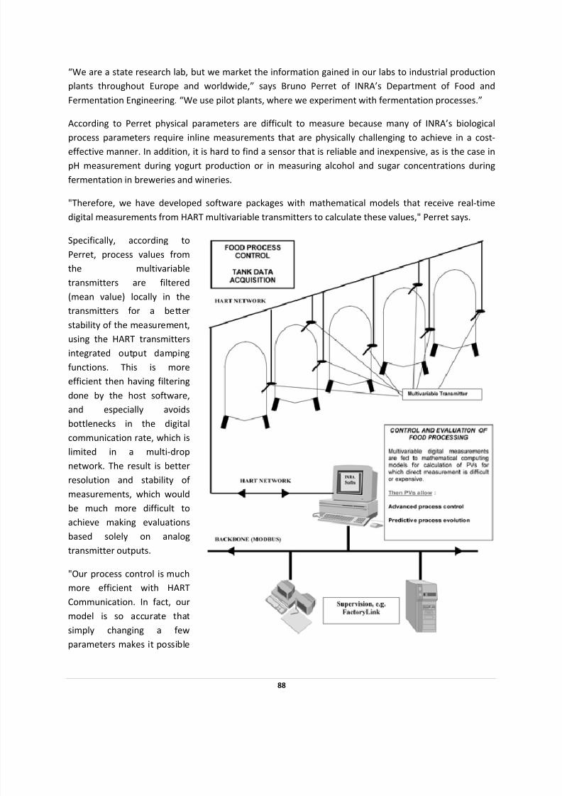
7/28/2019 HART Guide
http://slidepdf.com/reader/full/hart-guide 88/174
88
“We are a state research lab, but we market the information gained in our labs to industrial production
plants throughout Europe and worldwide,” says Bruno Perret of INRA’s Department of Food and
Fermentation Engineering. “We use pilot plants, where we experiment with fermentation processes.”
According to Perret physical parameters are difficult to measure because many of INRA’s biological
process parameters require inline measurements that are physically challenging to achieve in a cost‐effective manner. In addition, it is hard to find a sensor that is reliable and inexpensive, as is the case in
pH measurement during yogurt production or in measuring alcohol and sugar concentrations during
fermentation in breweries and wineries.
"Therefore, we have developed software packages with mathematical models that receive real‐time
digital measurements from HART multivariable transmitters to calculate these values," Perret says.
Specifically, according to
Perret, process values from
the multivariable
transmitters are iltered
(mean value) locally in the
transmitters for a better
stability of the m asurem nt,
using the HART transmitters
integrated output damping
functions. This is more
efficient then having filtering
done by the host software,
and especially avoids
bottlenecks in the digital
communication rate, which is
limited in a multi‐drop
network. The result is better
resolution and stability of
measurements, which would
be h more cult to
achieve making evaluations
based solely on analog
f
e e
muc diffi
transmitter outputs.
is
p
"Our process control is much
more efficient with HART
Communication. In fact, our
model so accurate that
simply changing a few
parameters makes it ossible
7/28/2019 HART Guide
http://slidepdf.com/reader/full/hart-guide 89/174
89
to predict the process evolution," Peret says. This last point is particularly important when the electrical
environment of a factory is noisy.
INRA has two trademarked HART software packages with HART technology‐derived master capabilities:
Oeno‐Beer Control, which is used to manage ethanol concentration and density; and YAB, a specialized
in in‐line pH estimation and trending routine used in yogurt production.
"With HART, the wiring is simple and economical, and measurement point maintenance is easy. So,
operating costs are low," Perret says. "But the best thing is HART instruments have a superb
measurement quality. The accuracy is just excellent. Most importantly, with HART digital data
transmission, the analog path in the measurement chain is shorter."
INRA was founded in 1946 and became a national public scientific and technological establishment in
1984 under the joint authority of the French Ministries of Research and Agriculture. Today INRA
operates 260 research centers, 80 experimental units and technological facilities and 100 service units.
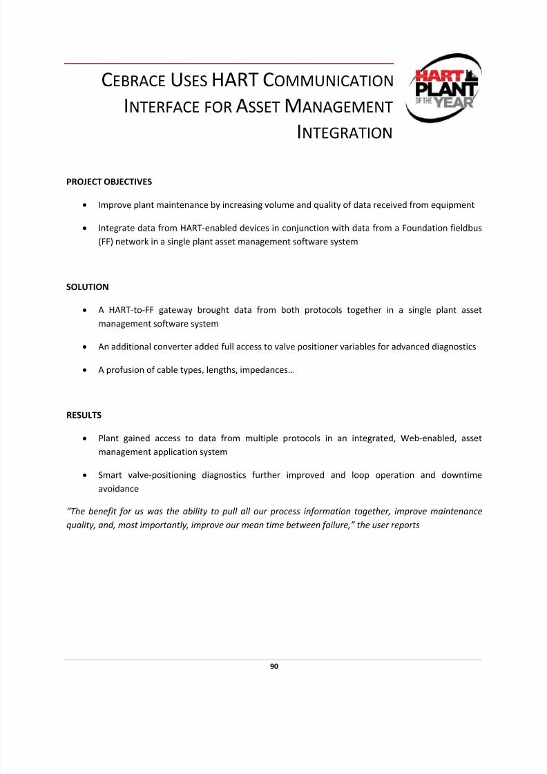
7/28/2019 HART Guide
http://slidepdf.com/reader/full/hart-guide 90/174
CEBRACE USES HART COMMUNICATION
INTERFACE FOR ASSET MANAGEMENT
INTEGRATION
PROJECT OBJECTIVES
• Improve plant maintenance by increasing volume and quality of data received from equipment
• Integrate data from HART‐enabled devices in conjunction with data from a Foundation fieldbus
(FF) network in a single plant asset management software system
SOLUTION
• A HART‐to‐FF gateway brought data from both protocols together in a single plant asset
management software system
• An additional converter added full access to valve positioner variables for advanced diagnostics
• A profusion of cable types, lengths, impedances…
RESULTS
• Plant gained access to data from multiple protocols in an integrated, Web‐enabled, asset
management application system
• Smart valve‐positioning diagnostics further improved and loop operation and downtime
avoidance
“The benefit for us was the ability to pull all our process information together, improve maintenance
quality, and, most importantly, improve our mean time between failure,” the user reports
90
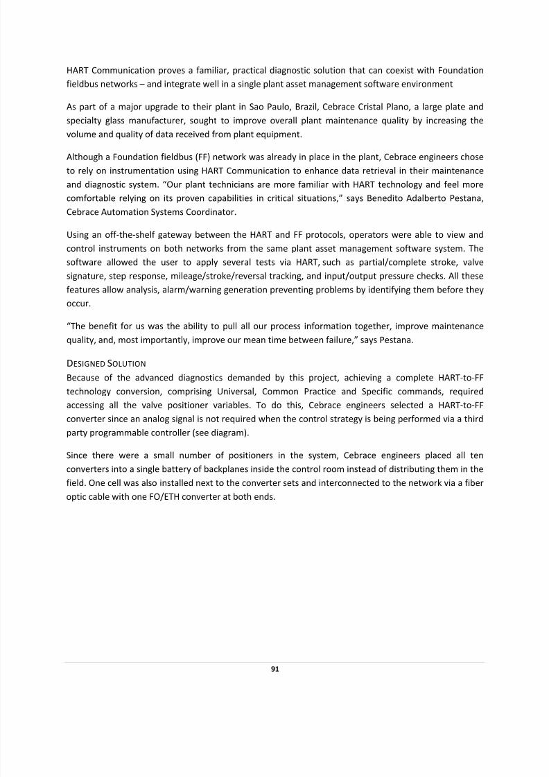
7/28/2019 HART Guide
http://slidepdf.com/reader/full/hart-guide 91/174
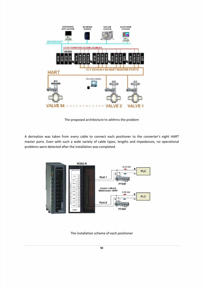
7/28/2019 HART Guide
http://slidepdf.com/reader/full/hart-guide 92/174
The proposed architecture to address the problem
A derivation was taken from every cable to connect each positioner to the converter’s eight HART
master ports. Even with such a wide variety of cable types, lengths and impedances, no operational
problems were detected after the installation was completed.
The installation scheme of each positioner
92
7/28/2019 HART Guide
http://slidepdf.com/reader/full/hart-guide 93/174
ASSET MANAGEMENT
“Our manufacturing facility is built around a huge linear machine hundreds of meters long. Any
disturbance, especially in the initial stages of the production process, can cause a major shutdown and,
even worse, destroy the main oven,” Pestana adds.
“If this occurs, set up and restart lasts a minimum of 60 hours, which represents a
cost of about $30,000US in lost product. Through the use of HART technology, we are able to maintain online
preventive maintenance full time and reduce maintenance costs at least 50 percent.”
HART integration allows Cebrace to monitor process‐related variables, diagnostic status, and
information stored in their database, such previous operation conditions, next scheduled shutdown for
maintenance, etc., 24 hours a day, seven days a week. They are able to access all field devices from
every station plant‐wide and even worldwide (if an Internet connection is available) in a single, web‐
based, integrated software environment to improve loop operation and to avoid unscheduled
downtime.
Conclusion
The main benefit of this integration project was that the plant gained access to data from all fieldbus as
well as HART‐enabled devices, in a single, integrated asset management application, at every station in
the plant as well as remotely using a secure Internet connection.
The high level of diagnostic data available via the HART smart valve positioner additionally allowed
access to information needed to improve loop operation and to avoid unscheduled downtime.
2003 HART Plant of the Year ‐ FINALIST
93
7/28/2019 HART Guide
http://slidepdf.com/reader/full/hart-guide 94/174
HART COMMUNICATION HELPS GAS PIPELINE COMPANY
MODERNIZE OPERATIONS AND SAVE
$1.25 MILLION ANNUALLY
PROJECT OBJECTIVES
• Replace paper chart recorders with cost‐effective digital communications
• Extend automated meter‐reading to a wireless network with an 80‐mile radius.
• Extend the HART Communication network beyond the traditional 10,000‐foot (3,000‐meter)
distance limitation.
SOLUTION
• Installed HART‐enabled network gateway/multiplexer for use with a multivariable flow
transmitter providing flow measurement and data logging
• Spread spectrum radios provided the wireless link, with multipoint and repeater configurations,
between the network gateway and the HART‐enabled instruments
RESULTS
• Reliable data acquisition from devices within a radius of up to 80 miles to a central host in Tulsa,
Oklahoma
• Data easily integrated with the pre‐existing measurement system.
• Eliminating manual paper‐based operations saves an annual $1.25 million
• Additional savings include elimination of costly cable runs and hardware savings of almost 30%
on future instrumentation installations
When a major Midwestern gas pipeline company sought to modernize its legacy paper ‐based meter ‐
reading operations, HART technology proved equal to the challenge by providing a capable, flexible and
cost ‐saving solution.
94

7/28/2019 HART Guide
http://slidepdf.com/reader/full/hart-guide 95/174
In an extraordinary automation project involving multiple “wireless” messaging links, the power and
adaptability of the HART Communication helped a major Midwestern gas pipeline company meet the
challenge of modernizing its analog meter‐reading infrastructure. HART technology provided the
communication tool needed to create an extended meter reading network via spread spectrum radio
and satellite communication.
The gas pipeline company planned to replace paper chart recorders on their natural gas pipeline with an
automated meter reading (AMR) system. The AMR system would have to be capable of acquiring data
from devices within a radius of up to 80 miles, publishing field data from locations throughout the
Midwest to a central host in Tulsa, Oklahoma, and integrating the data with an existing measurement
system.
To meet the challenge, company engineers chose the Director, a HART‐enabled network
gateway/multiplexer from Arcom Control Systems used in conjunction with a multivariable flow
transmitter providing flow measurement and data logging capabilities.
“The HART master satisfied all the requirements for the project,” says John Tandy of Arcom Control
Systems. “The Director uses HART to acquire real‐time and historical information. Data is then published
to a central host via satellite or over Ethernet via TCP/IP.”
95
7/28/2019 HART Guide
http://slidepdf.com/reader/full/hart-guide 96/174
The AMR system uses spread spectrum radio and satellite communication to extend the HART network
beyond the traditional 10,000‐foot (3,000‐meter) distance limitation. Spread spectrum provides the
wireless link between the Director and the HART instruments.
Tandy adds that the radios “allow great flexibility in network architecture through multipoint and
repeater configurations, as well as providing reliable data transmission of the HART messages,” Tandy adds. “With the use of repeaters, HART units can be brought into a single multiplexer from a radius of 80
miles or more.”
At each remote site the Freewave radio connects to the field devices using a serial HART interface. This
transmits the HART signal from the radio onto the local current loop to a single or multi‐dropped HART
network. Because up to 32 devices per radio network were required, the HART “poll by tag” feature was
implemented to allow more than the traditional 15 devices.
By implementing the HART‐based AMR system, the pipeline company was able to realize cost savings in
several ways. The paper chart recorders previously had to be collected and tabulated manually for each
monthly billing. Now this is done automatically with ongoing savings estimated at $1.25 million per year.
Because the HART signal is transferred over the radio link, there is no need for a separate Remote
Terminal Unit (RTU) or multiplexer at each meter site. One Director is master to 32 HART meters,
allowing data consolidation.
Wireless communication avoids very costly cable runs to each HART meter. The multivariable flow
transmitter effectively combines a traditional flow meter and three discrete instruments into a single
instrument, yielding hardware cost savings of almost 30% per site. TCP/IP communication allows remote
diagnostics and configuration, reducing the need for on‐site technical support.
Global
industry
growth
continues
to
present
an
ever‐
increasing
challenge
to
provide
strong
networking
and interoperability communications solutions. HART technology has demonstrated for more than a
decade that it is capable of meeting the challenge.
96
7/28/2019 HART Guide
http://slidepdf.com/reader/full/hart-guide 97/174
HART‐TO‐ETHERNET GATEWAY: TWO DIVERSE
APPLICATIONS, ONE SOLUTION
What does a large refinery have in common with a 650 year‐old wheat mill? A common HART Protocol, and a simple solution to a sometimes complicated problem in the HART‐to‐Ethernet gateway.
Numerous automation suppliers offer off ‐the‐shelf gateways to bridge the data divide between the
HART protocol and many industrial Ethernet protocols. These gateways provide a highly effective means
of bring data from HART devices in the field and any host computer or device on the Ethernet network.
Consider these two very different plant environments…
REFINERY – MEXICO
PROJECT OBJECTIVES
• In Mexico, a PEMEX refinery required a means of integrating of all HART‐compatible field
devices into one user program.
SOLUTION
• Installed autonomous 100Mbit Ethernet Network (HART‐LAN), ring topology with optical
Ethernet ports, conversion from RS485 using COM servers and HART LANs to accesses devices
RESULTS
• Each satellite room got a COM server; RS485 bus line extended as a two‐wire cable as a bus line
connecting to HART multiplexer; HART Server automation interface allows user monitoring.
• PEMEX refinery uses HART‐to‐Ethernet Gateway Web Server to integrate 10,230 analog inputs
and 2,430 analog outputs to satellite rooms up to 3 kilometers away
Faced with a daunting integration task, the PEMEX refinery in Madero, Mexico, turned to HART
Communication for a viable solution. A part of the overall requirement of the project was the full
integration of all HART ‐enabled field devices for parameter assignment and configuration into one user
program.
97

7/28/2019 HART Guide
http://slidepdf.com/reader/full/hart-guide 98/174
Access to these field devices had to be via both a central computer with a back‐up system and
individually using a Notebook in each individual satellite room. This involved the transfer of a total of
10,230 analog inputs and 2,430 analog outputs via 728 HART multiplexers (211 masters, 517 slaves).
Distance to the individual satellite rooms was up to 3km.
In order to effect the required functionality, engineers decided in favor of an autonomous 100Mbit Ethernet Network (HART‐LAN). A ring structure topology was selected with automatic redundancy
switchover. The ring structure was achieved by interconnecting the optical ports of the Ethernet
switches in the CCR bunker.
Successful conversion from Ethernet to RS485 interfaces in the satellite rooms has been achieved
through the use of COM servers. These devices are set to a specific IP address and can be addressed
through the corresponding device driver via Ethernet as an outlying RS485 interface. Thus, every station
on the HART LAN has access to these devices, which proved to be an excellent solution for individual
access via the Notebooks.
One COM server has been installed per satellite room and the RS485 bus line has been extended as a
two‐wire cable. Up to 15 HART multiplexer masters are connected to this bus line. The central
computers and the Notebooks are equipped with seven software packages, including the HART Server
automation interface.
98
7/28/2019 HART Guide
http://slidepdf.com/reader/full/hart-guide 99/174
WHEAT MILL – GERMANY
PROJECT OBJECTIVES
• Ancient German wheat mill needed to transfer radar level‐sensor data from silos to the control
room
SOLUTION
• HART‐to‐Ethernet Gateway acts as a Web server, sending data via wireless LAN to control room
RESULTS
• Process variables displayed in standard Web browser; no new cabling needed to bring data to
control room.
• In Germany, the H. Thylmann Kilianstädtermühle wheat mill needed to transfer radar level
sensor data from silos to the control room.
A 650‐year‐old wheat mill near Frankfurt, Germany, is now linked with 21st Century process automation
thanks to the power of HART Communication used to send data from silos to the mill’s control room via
a standard Web browser.
The H. Thylmann stores bran in six silo tanks of 40‐ to 60‐tons capacities. The mill equipped the silos
with guided radar level sensors that monitor tank levels. A HART‐enabled multiplexer scans and collects
the analog and digital data from the level transmitters.
The data is fed to a HART‐to‐Ethernet gateway which acts as a web server. The data is then transmitted
via a wireless LAN to the control room located about 40 meters away and displayed as process values by
using a standard Web browser.
“There was no new cabling to the control room needed,” says Thomas Funfgeld, the mill’s
instrumentation manufacturer representative. “All equipment could be mounted in a single cabinet near
the silo tanks. Also, the HART data is available via the network to all users in the company.”
Visualizing
the
data
with
a
standard
Web
browser
saves
additional
money
because
custom
display
software is not required. This is another example of how HART Communication, when used in a real‐
time process application, can provide simple, cost‐effective solutions that can reduce operating costs
and improve process operations.
99
7/28/2019 HART Guide
http://slidepdf.com/reader/full/hart-guide 100/174
PETROPRIAR USES HART TECHNOLOGY
TO STREAMLINE PREVENTIVE
MAINTENANCE PROCESS
PROJECT OBJECTIVES
• Achieve trouble‐free plant startup of a 248,000 barrel/day oil processing facility
• Eliminate erratic performance of under‐performing field devices in a DCS network of 5,000
instruments
SOLUTION
• Addition of asset‐managing software system platform to its DCS
• Use the combined platform's HART technology to access intelligent device diagnostic
information and root‐out "bad actor" devices to be eliminated and/or replaced
RESULTS
• Streamlined work processes led to reduced maintenance costs for a 60% reduction in lost profit
opportunities valued at $70 million in two years
• Instrumentation performance and calibration problems were prevented before startup. Number
of failures attributed to instrumentation during startup? Zero
• Since startup, HART technology has streamlined preventive maintenance, allowing this large
plant to operate with a staff of only five reliability engineers and 12 instrument technicians
One of Venezuela’s major producing oil fields lies in its Orinoco River basin; however, crude from this field is
extra
heavy
and
must
undergo
upgrading
in
one
of
several
plants
before
refining.
One
of
those
plants
is
using HART Communication to streamline operations and their preventive maintenance process.
100
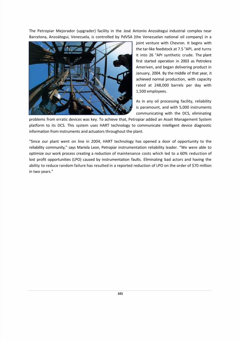
7/28/2019 HART Guide
http://slidepdf.com/reader/full/hart-guide 101/174
The Petropiar Mejorador (upgrader) facility in the José Antonio Anzoátegui industrial complex near
Barcelona, Anzoátegui, Venezuela, is controlled by PdVSA (the Venezuelan national oil company) in a
joint venture with Chevron. It begins with
the tar‐like feedstock at 7.5 °API, and turns
it into 26 °API synthetic crude. The plant
first started operation in 2003 as Petrolera
Ameriven, and began delivering product in
January, 2004. By the middle of that year, it
achieved normal production, with capacity
rated at 248,000 barrels per day with
1,500 employees.
As in any oil processing facility, reliability
is paramount, and with 5,000 instruments
communicating with the DCS, eliminating
problems from erratic devices was key. To achieve that, Petropiar added an Asset Management System
platform to its DCS. This system uses HART technology to communicate intelligent device diagnostic
information from instruments and actuators throughout the plant.
“Since our plant went on line in 2004, HART technology has opened a door of opportunity to the
reliability community,” says Mariela Leon, Petropiar instrumentation reliability leader. “We were able to
optimize our work process creating a reduction of maintenance costs which led to a 60% reduction of
lost profit opportunities (LPO) caused by instrumentation faults. Eliminating bad actors and having the
ability to reduce random failure has resulted in a reported reduction of LPO on the order of $70 million
in two years.”
101

7/28/2019 HART Guide
http://slidepdf.com/reader/full/hart-guide 102/174
Petropiar’s maintenance group found that their efforts using HART technology made the plant startup
go much smoother, as instrumentation performance and calibration problems had been sought out and
corrected before it went on line. As a result, there were no failures attributed to instrumentation
reported during the startup period. Their bad actors had already been identified and corrected,
eliminating
95%
of
related
problems.
Since startup, this preventive method has continued. Calibration tasks are thoroughly defined, with
routes and schedules laid out for the entire universe of instrumentation. This emphasis on predictive
maintenance allows them to attend to only the items that really need attention, resulting in a 10%
increase in effective personnel “wrench time.” This has allowed the plant to operate with a staff of only
five reliability engineers and 12 instrument technicians and still stay ahead of most problems.
These experiences have caused th e reliability team to look for other opportunities where HART
has not already been put to work. There is still a small population of installed devices that are not
HART capable, but these will be upgraded. All new instruments and process analyzers must be HART
compliant.
Moreover, all systems have not yet been integrated into the AMS, but this is also underway. Some parts
of the safety instrumented system (SIS), some PLC driven subsystems, and the fire and gas (F&G) detection
system are still being incorporated into the larger asset management network.
102

7/28/2019 HART Guide
http://slidepdf.com/reader/full/hart-guide 103/174
One example of this increased reliability relates to valve positioners. “HART technology was used to
pinpoint a bad valve positioner which provided the justification to change or add positioners to 400
valves,” says Livia Lefebre, reliability superintendent. “We also demonstrated the partial valve stroke
application to management who then approved its use, significantly increasing the time between
required shutdowns.”
HART technology is also used at the oil production site that feeds Petropiar, and by the end of 2008 the
two systems will be interconnected. This will allow the reliability engineers at the upgrader to analyze
what’s happening upstream as well.
2008 HART Plant of the Year
103
7/28/2019 HART Guide
http://slidepdf.com/reader/full/hart-guide 104/174
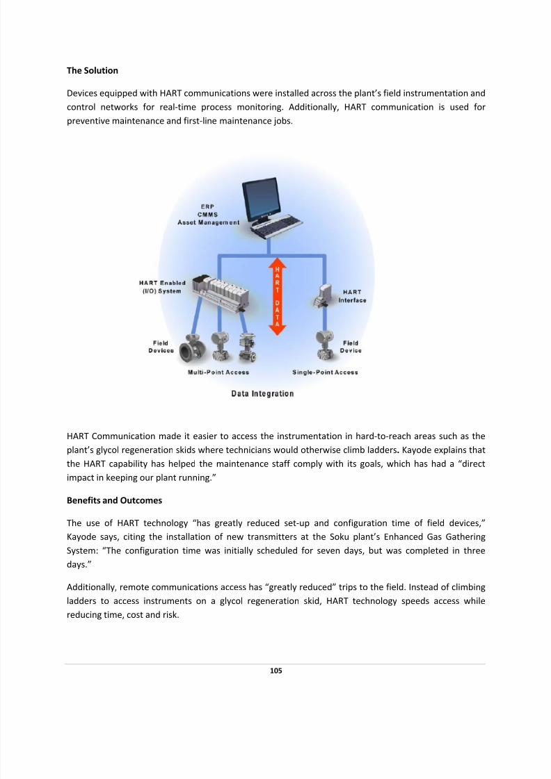
7/28/2019 HART Guide
http://slidepdf.com/reader/full/hart-guide 105/174
The Solution
Devices equipped with HART communications were installed across the plant’s field instrumentation and
control networks for real‐time process monitoring. Additionally, HART communication is used for
preventive maintenance and first‐line maintenance jobs.
HART Communication made it easier to access the instrumentation in hard‐to‐reach areas such as the
plant’s glycol regeneration skids where technicians would otherwise climb ladders. Kayode explains that
the HART capability has helped the maintenance staff comply with its goals, which has had a “direct
impact in keeping our plant running.”
Benefits and Outcomes
The use of HART technology “has greatly reduced set‐up and configuration time of field devices,”
Kayode says, citing the installation of new transmitters at the Soku plant’s Enhanced Gas Gathering
System: “The configuration time was initially scheduled for seven days, but was completed in three
days.”
Additionally, remote communications access has “greatly reduced” trips to the field. Instead of climbing
ladders to access instruments on a glycol regeneration skid, HART technology speeds access while
reducing time, cost and risk.
105

7/28/2019 HART Guide
http://slidepdf.com/reader/full/hart-guide 106/174
Kayode adds that plant work processes and operations have been “greatly improved” through the better
data visibility the HART Protocol provides, which he sums up as “knowing the status of field devices and
be able to be proactive in their maintenance.”
106
7/28/2019 HART Guide
http://slidepdf.com/reader/full/hart-guide 107/174
STATOILHYDRO USES HART
COMMUNICATION TO DELIVER NATURAL
GAS FROM UNDER THE SEA
PROJECT OBJECTIVES
• Optimize efficiency in communicating data from an undersea gas field of 24 wells to a 1,200 km
long undersea pipeline—the longest ever built
• Minimize the staff required to effectively manage communications with the control system
SOLUTION
• An distributed control system was installed with secondary controllers at substations to handle
the interfaces with field devices
• Approximately 1,400 HART‐enabled field devices were connected to the system full‐time
• Several traditional 4‐20mA anti‐surge valves were connected to HART multiplexers to allow their
data can be converted for communication
• A videoconferencing application lets experts around the world collaborate on diagnosing and
correcting problems as they arise
RESULTS
• HART technology helped the plant meet a commissioning schedule
• Diagnostic data enhance compliance with the company's Total Reliability Initiative for higher
efficiency, asset availability and safety
• A full‐time connection between HART‐enabled devices and the control system’s asset
optimization package allows real‐time tracking, troubleshooting and fault diagnosis
By designing in the advanced communication and self ‐diagnostics capabilities of HART technology,
Norway’s StatoilHydro and its partners started efficiently delivering natural gas to the U.K.
107

7/28/2019 HART Guide
http://slidepdf.com/reader/full/hart-guide 108/174

7/28/2019 HART Guide
http://slidepdf.com/reader/full/hart-guide 109/174
But Ormen Lange is not easy to exploit. The gas field itself lies roughly 3000 meters below sea
level, buried beneath an uneven seabed and sitting under 800 to 1100 meters of water. Situated
120 km off the coast of Norway, the site experiences some extreme natural conditions. There are
subzero temperatures, whether measured in Fahrenheit or Centigrade, most of the year. The seas
are stormy, with strong underwater currents.
Subsea wells in seabed templates
The project that brought this fuel up from the bottom of the sea and into British homes consists of
a 24 subsea wells in four seabed templates. The output of the wells is sent in pipes 120 km to
Nyhamna on the island of Aukra on the west coast of Norway. There the fuel is processed and
readied for shipment to the U.K. via a 1200 km long undersea pipeline.
Ramberg notes that direct pumping of the fuel to shore‐based processing won’t be problematic
because special steps are taken to prevent pipe‐clogging due to freezing of the liquid. That’s done
with an on‐shore monoethylene glycol (MEG) plant. “We pump the MEG liquid out to the wells,
inject it in the pipelines and transport it with the gas to shore to prevent freezing.”
Meeting the Challenge for Less
Once onshore, the MEG is removed and reused. The fuel then has to be processed and readied for
shipment to the U.K.
When designing the plant, StatoilHydro faced several constraints. One was the remote location,
another was the sometimes harsh weather, and a third was the size of the facility. As finally built,
the on‐shore plant is one square km, with a main control room and 10 substations. “This plant is
109
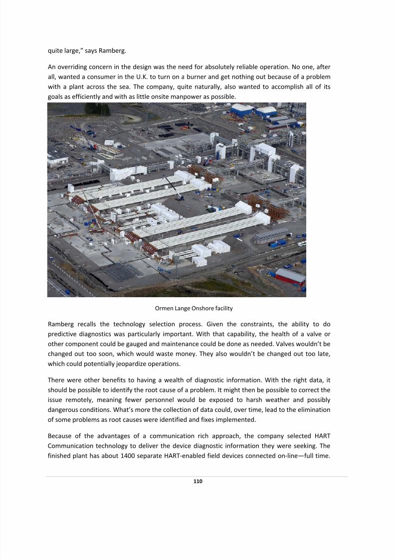
7/28/2019 HART Guide
http://slidepdf.com/reader/full/hart-guide 110/174

7/28/2019 HART Guide
http://slidepdf.com/reader/full/hart-guide 111/174
Of these, about 350 are valve positioners, with most of the rest transmitters. A handful of
traditional 4‐20 mA anti‐surge valves are connected to HART multiplexers so that their data can be
converted for communication.
Control is handled by a DCS with secondary controllers in the substations handling the interface
between local devices and the plant‐wide controller. As might be expected given the need for reliability, there are redundancies and intelligent approaches built into the setup. Some of these
aren’t those typically thought of or used. For example, there’s a robust video conferencing
capability so that experts from around the world can meet virtually to help diagnose problems and
propose solutions.
After processing at the plant, the fuel begins a trek to the U.K., traveling 1200 km before arriving
at a terminal at Easington at the other end. “It is a very long pipeline. I think it is the longest
subsea pipeline so far,” says Ramberg.
111
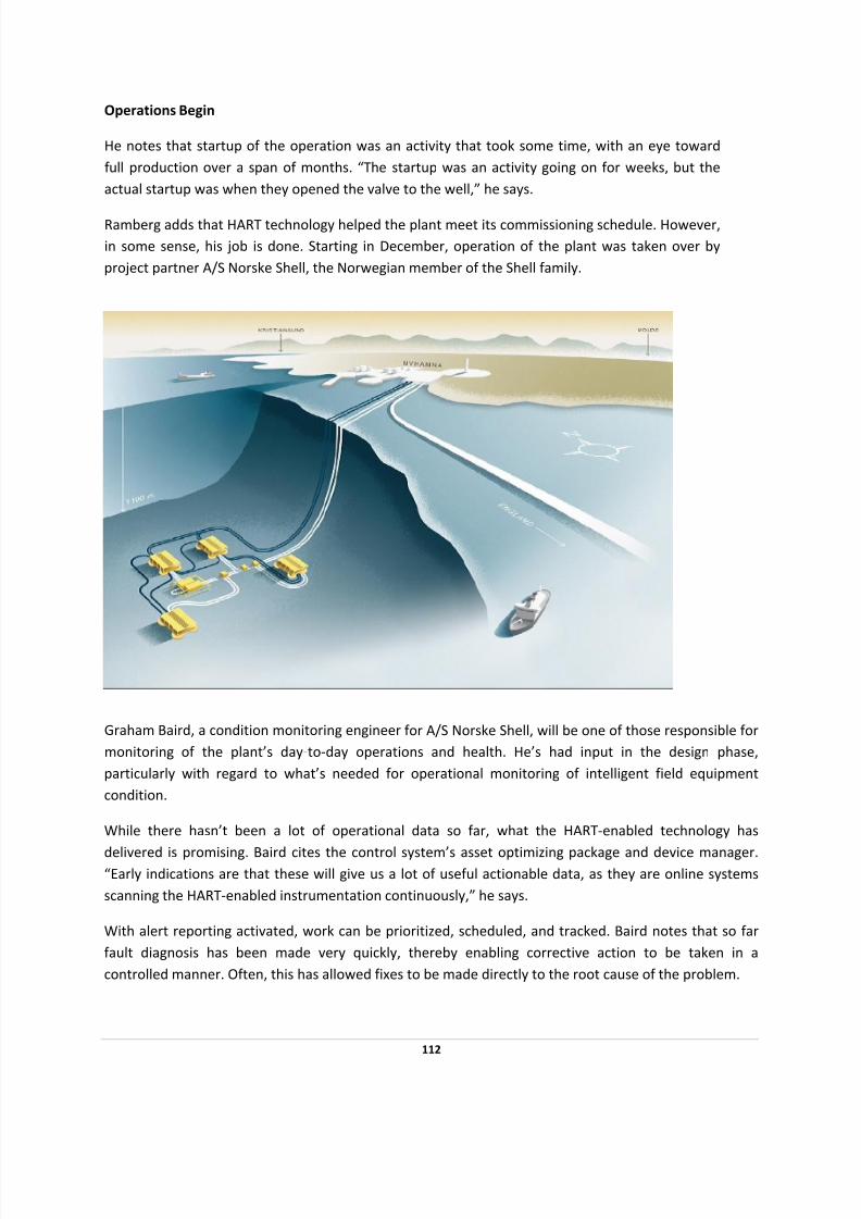
7/28/2019 HART Guide
http://slidepdf.com/reader/full/hart-guide 112/174
Operations Begin
He notes that startup of the operation was an activity that took some time, with an eye toward
full production over a span of months. “The startup was an activity going on for weeks, but the
actual startup was when they opened the valve to the well,” he says.
Ramberg adds that HART technology helped the plant meet its commissioning schedule. However,
in some sense, his job is done. Starting in December, operation of the plant was taken over by
project partner A/S Norske Shell, the Norwegian member of the Shell family.
Graham Baird, a condition monitoring engineer for A/S Norske Shell, will be one of those responsible for
monitoring of the plant’s day‐to‐day operations and health. He’s had input in the design phase,
particularly with regard to what’s needed for operational monitoring of intelligent field equipment
condition.
While there hasn’t been a lot of operational data so far, what the HART‐enabled technology has
delivered is promising. Baird cites the control system’s asset optimizing package and device manager. “Early indications are that these will give us a lot of useful actionable data, as they are online systems
scanning the HART‐enabled instrumentation continuously,” he says.
With alert reporting activated, work can be prioritized, scheduled, and tracked. Baird notes that so far
fault diagnosis has been made very quickly, thereby enabling corrective action to be taken in a
controlled manner. Often, this has allowed fixes to be made directly to the root cause of the problem.
112
7/28/2019 HART Guide
http://slidepdf.com/reader/full/hart-guide 113/174
There also can be synergies with other non‐HART condition monitoring systems. For example,
compressor performance can be influenced by surge valve conditions, instrumentation calibrations, and
so on. With more diagnostics data available, it’s possible to cross reference between systems to
establish why equipment may not appear to be performing according to design.
“All in all we get a much better overall view of the plant asset condition right now” sums up Baird.
He explains that the use of HART technology and the wealth of diagnostic information it provides aligns
with Shell’s Total Reliability Initiative. Getting that more informative picture also helps plant operators
rest easier at night, Baird says.
“Having a large number of instruments and valves connected to the HART‐based systems for diagnostics
can help us achieve a high availability for safety related instruments, critical process instruments and
control valves. This gives plant operators the confidence that they have properly operating control
equipment.”
Thus, an intelligent application of HART technology helps keep the U.K warm. With the predictive diagnostic capabilities built into the system, the Ormen Lange plant should be able to do so in a cost‐
effective manner for years to come.
2007 HART Plant of the Year
113
7/28/2019 HART Guide
http://slidepdf.com/reader/full/hart-guide 114/174
CLARIANT USES HART TECHNOLOGY TO
SOLVE MAJOR PRODUCTION PROBLEM
PROJECT OBJECTIVES
• Re‐configured field devices from a safe area to adapt to a new production batches.
SOLUTION
• Create a centralized system that would allow access to and modification of the HART devices
currently installed in the plant via a Remote Device Management concept
• Centralized access to all devices and centralized the database and management of our
instruments.
• HART Communication is used to deliver the process measurement values and device
configuration information to a PROFIBUS‐Remote‐I/O system, which converts the data to cyclic
PROFIBUS DP Data.
• The data and device information is viewed daily
RESULTS
• Initial investment cost was low since installed devices were HART‐capable
• By saving just 2 or 3 hours of downtime, initial investment could be recovered
• Plant engineers have determined that this project has reduced downtime by at least 60‐70%
•
Changing
device
parameters
to
adjust
for
a
new
product
is
now
faster
and
easier
• Device problems and errors can now be quickly analyzed
• Accessing data from devices in hazardous area is not longer a problem
• Equipment replacement (when necessary) is now faster
114

7/28/2019 HART Guide
http://slidepdf.com/reader/full/hart-guide 115/174
115
• Predictive maintenance alerts enable problems to be detected within seconds and process
disruptions to be avoided
• Real‐time access to field devices provides assurance that things are working properly
“The return on investment is very high when you use the HART technology that is already in your plant.”
Rather than waiting for a “perfect” solution that may require a significant investment, plant managers
should look at the technologies they already have for a viable solution to improve operational
performance.
The Clariant antioxidants plant in Gersthofen, Germany, solved a major production problem by utilizing
the resources already installed in their plant. Clariant uses HART Communication technology in their
daily operations to deliver process measurement values and device configuration information to a
PROFIBUS remote I/O system, which converts the data to cyclic PROFIBUS DP Data for real‐time data
access, preventive maintenance and troubleshooting of critical devices located in a hazardous area.
“The return on investment is very high when you use the HART technology that is already in your plant,”
says Ludwig Wenninger, Clariant plant engineer. “Going to the device in the field took a lot of time. Now
we can access parameters from a central location in a safe area which has reduced the duration of
planned shutdowns by at least 60 to 70 percent.”
The Clariant plant produces additives used in plastics production and is responsible for prototyping new
production plants. Because of the
numerous chemicals produced,
their
field
devices
need
to
be
re‐
configured frequently to adapt to
a new production batch. Many of
the devices are located in a
hazardous area, which limits
accessibility, so a plan was
devised to allow access to smart
devices from a safe, remote
(away from the devices) location.
“To create a centralized system
that would allow access to and
modification of the HART devices
currently installed in the plant, we
decided on a Remote Device Management concept,” says Wenninger. “The system is based on
PROFIBUS‐Ethernet gateways and uses several automation technologies working together to provide a
cost‐effective solution.”

7/28/2019 HART Guide
http://slidepdf.com/reader/full/hart-guide 116/174
Since 1995, the Clariant plant has used numerous HART‐enabled devices from multiple suppliers.
Because HART technology is defined by a standard specification, all devices were able to be included in
the application regardless of supplier, device age or measurement type. HART provides the means of
remote device configuration to meet two of the projects main requirements.
Some of the devices were installed in hazardous areas and a notebook PC and other configuration tools could not be used in those areas. Since accessibility and management of the different devices would
provide faster process adjustments and possibly provide early notification of pending device problems,
the plan needed to provide central access to the intelligent HART devices from a safe, remote location to
eliminate the need for routine visits to the hazardous areas.
“We wanted to use the possibility of device adjustments and remote configuration which is built into the
HART devices,” says Wenninger. “We wanted to centralize access to all devices and to centralize the
database and management of our instruments. So, we decided on a structure where the devices and
their information were available full‐time and would always be connected to the system.”
HART Communication is used to deliver the process measurement values and device configuration
information to a PROFIBUS‐Remote‐I/O system, which converts the data to cyclic PROFIBUS DP Data.
The remote I/O from R. Stahl was selected for this application since it is designed as intrinsically safe and
can provide access to devices in the hazardous area.
116

7/28/2019 HART Guide
http://slidepdf.com/reader/full/hart-guide 117/174
The link to the hazardous area is a RS‐485 intrinsically safe option of PROFIBUS, converting to Standard‐
RS‐485 and then to the PROFIBUS Master gateway by Softing and to the Delta V Field Controller supplied
by Emerson Process Management.
“The Clariant project is an ideal example of how to use installed HART‐smart devices to their maximum
potential—in other words, finding better ways to use what you have,” says Ron Helson, HART Communication Foundation Executive Director. “Real‐time integration of HART data with plant control,
safety and asset management systems unleashes the Power of HART technology and provides significant
benefits in all phases of the plant life cycle.”
The data and device information is viewed daily and has provided several expected and unexpected
results.
• Initial investment cost was low since installed devices were HART‐capable
• By saving just 2 or 3 hours of downtime, initial investment could be recovered
• Plant engineers have determined that this project has reduced downtime by at least 60‐70%
• Changing device parameters to adjust for a new product is now faster and easier
• Device problems and errors can now be quickly analyzed
• Accessing data from devices in hazardous area is not longer a problem
• Equipment replacement (when necessary) is now faster
• Predictive maintenance alerts enable problems to be detected within seconds and process
disruptions to be avoided
• Real‐time access to field devices provides assurance that things are working properly
Combining HART with other automation solutions delivers real‐time benefits to the Clariant plant 24
hours a day, 7 days a week. Re‐configuration of the process to include a new product is now much faster
and is accomplished with significantly less time, effort and cost. The ability to diagnose the overall plant
operation is considerably enhanced. Downtime due to device re‐configuration has been greatly reduced
and has already provided complete recovery of initial investment.
HART Communication technology is the “right tool” for management of all field devices delivering data
to the control system and device monitoring applications. Justifying the cost for the hardware and
software needed for this type of project is easy because the installed HART devices can be used.
2004 HART Plant of the Year
117

7/28/2019 HART Guide
http://slidepdf.com/reader/full/hart-guide 118/174
BP COOPER RIVER USES HART DIAGNOSTICS
TO SAVE ON MAINTENANCE AND INCREASE
PRODUCTIVITY
PROJECT OBJECTIVES
• Gain diagnostic data on hundreds of control valves to pinpoint problems during scheduled
shutdowns
• Migrate to new technology with minimal production downtime for installation
• Make use of existing wiring and be compatible with existing valves and transmitters
SOLUTION
• A phased upgrade to intelligent valve positioners caused “no major disruptions to the operation”
• A multiplexer was added to send digital HART device data to an asset management system,
while also allowing analog signals to pass to the control system.
• To accommodate an older, analog control system, a converter translated digital HART device
data where needed between HART‐enabled positioners and 4‐20mA signals.
RESULTS
• HART‐enabled devices provided process, status and diagnostic data to provide actual valve
positions, act as control system position switches and eliminate extra field devices and wiring.
• Plant availability has increased to about 96 percent, and site output rose more than 25 percent
in part due to the use of HART technology
• Plant personnel need only pull five or six valves during a plant shutdown instead of 35 to 50 to
save “hundreds of thousands of dollars per year in maintenance and production costs,” BP
reports.
“We are saving hundreds of thousands of dollars per year in maintenance and production costs,” reports
a specialist at BP Cooper River, which supplies one‐third of the world’s supply of a vital ingredient in
118
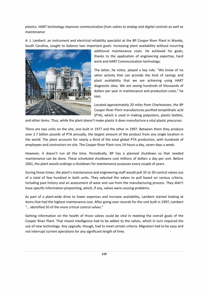
7/28/2019 HART Guide
http://slidepdf.com/reader/full/hart-guide 119/174
119
plastics. HART technology improves communication from valves to analog and digital controls as well as
maintenance
A. J. Lambert, an instrument and electrical reliability specialist at the BP Cooper River Plant in Wando,
South Carolina, sought to balance two important goals: increasing plant availability without incurring
additional maintenance costs. He achieved his goals, thanks to the application of engineering expertise, hard
work and HART Communication technology.
The latter, he notes, played a key role. “We know of no
other activity that can provide the kind of savings and
plant availability that we are achieving using HART
diagnostic data. We are saving hundreds of thousands of
dollars per year in maintenance and production costs,” he
says.
make plastic it does manufacture a vital plastic precursor.
Located approximately 20 miles from Charlestown, the BP
Cooper River Plant manufactures purified terephthalic acid
(PTA), which is used in making polyesters, plastic bottles,
and other items. Thus, while the plant doesn’t
There are two units on the site, one built in 1977 and the other in 1997. Between them they produce
over 2.7 billion pounds of PTA annually, the largest amount of the product from any single location in
the world. The plant accounts for nearly a third of the total global PTA production, with hundreds of
employees and contractors on site. The Cooper River Plant runs 24 hours a day, seven days a week.
However,
it
doesn’t
run
all
the
time.
Periodically,
BP
has
a
planned
shutdown
so
that
needed
maintenance can be done. These scheduled shutdowns cost millions of dollars a day per unit. Before
2001, the plant would undergo a shutdown for maintenance purposes every couple of years.
During those times, the plant’s maintenance and engineering staff would pull 35 to 50 control valves out
of a total of few hundred in both units. They selected the valves to pull based on various criteria,
including past history and an assessment of wear and use from the manufacturing process. They didn’t
have specific information pinpointing, which, if any, valves were causing problems.
As part of a plant‐wide drive to lower expenses and increase availability, Lambert started looking at
items that had the highest maintenance cost. After going over records for the unit built in 1997, Lambert
“… identified 50 of the more critical control valves.”
Getting information on the health of those valves could be vital in meeting the overall goals of the
Cooper River Plant. That meant intelligence had to be added to the valves, which in turn required the
use of new technology. Any upgrade, though, had to meet certain criteria. Migration had to be easy and
not interrupt current operations for any significant length of time.

7/28/2019 HART Guide
http://slidepdf.com/reader/full/hart-guide 120/174
The investment needed to be minor and benefits readily attainable. Those parameters implied that any
solution would have to run over existing wiring and be compatible with the mix of valves and
transmitters already in place, a combination that varied by plant unit. For instance, at the time the 1997
unit had smart transmitters but no smart positioners and an analog control system. The 1977 unit had a
different blend of technologies.
Getting Smart
Around 2000, BP had spent thousands of dollars installing diagnostic software. At the time the project
had been justified in order to get information from a single valve. That installation introduced the HART
Communication protocol into the plant, and Lambert started looking into getting valve diagnostics from
other locations using the HART signal. After a bit of investigation, Lambert and others were convinced
that not only could this be done but that it could be done using the wiring already in place.
Therefore, they proposed a HART‐centered upgrade, which plant management approved. The project
was completed over the next few years without a problem. “The upgrade to intelligent positioners was
phased in over time with no major disruptions to the operation,” says Lambert.
Because of differences between the units, various hurdles had to be overcome. One was the analog
control system in the 1997 unit. The BP team solved this through the use of a converter, which
transformed digital HART data from the positioner into 4‐20mA signals that the analog control system
could understand.
120
7/28/2019 HART Guide
http://slidepdf.com/reader/full/hart-guide 121/174
7/28/2019 HART Guide
http://slidepdf.com/reader/full/hart-guide 122/174
NEW YORK POWER UTILITY USES HART TO REDUCE
COSTS AND IMPROVE RELIABILITY
PROJECT OBJECTIVES
• Monitor and control pressure data
• Enable monitoring of AC power status, which 4‐20mA analog wiring could not do
• Reduce costs by eliminating a remote terminal unit (RTU) or programmable logic controller (PLC)
SOLUTION
• Eliminated the need for a mini RTU or PLC at each remote measurement site
• Eliminated the need for as well as an analog modem at each remote measurement site
RESULTS
• Saving approximately $700 per site
• Facilitates future improvements to reliability, redundancy and regional customer service
Public infrastructure projects are necessary but power utilities face ongoing challenges to provide the
most reliable, cost ‐effective service possible. In keeping with this need, Mark Viglucci at the public power
utility of National Grid, Niskayuna, N.Y., used HART technology to reduce costs and improve reliability.
What Needed to Happen
The evolution toward digital communication raised the possibility of finding more cost‐effective ways to
manage Supervisory Control and Data Acquisition (SCADA) systems than to continue using a traditional 4‐20mA remote terminal unit (RTU) or programmable logic controller (PLC) at each remote
measurement and control installation. Additionally, Viglucci found that traditional analog wiring could
not handle all monitoring jobs needed for SCADA system troubleshooting and field diagnostics.
122
7/28/2019 HART Guide
http://slidepdf.com/reader/full/hart-guide 123/174
“Typically these sites have two pressures and one DI alarm for AC power status. Unfortunately, the AC
power status can't be monitored,” he said.
The Solution
Viglucci decided to use HART technology in an experiment to eliminate unnecessary hardware in the
utility’s SCADA system. At two sites, for example, three transmitters were being polled at two different
sites by a compact programmable SCADA RTU/controller transmitting data across leased analog data
lines.
For signal level and four‐wire to two‐wire conversion, he designed “a simple interface board containing
only four ICs,” with the telephone company providing the bridging to allow multiple stations and
numerous HART transmitters to be polled (using long‐frame addressing), and data to be received in real
time.
Benefits and Outcome
The test was a success. Eliminating a controller (RTU or PLC) and analog modem, per‐site savings are
$700, according to Viglucci. AC power can now be brought into the maintenance program for greater
system reliability. This strategy sets the stage for cumulative savings as sites are added or retrofit, while
laying the groundwork for National Grid to make continual improvements in serving its customers.
123
7/28/2019 HART Guide
http://slidepdf.com/reader/full/hart-guide 124/174
OHIO STATE UNIVERSITY USES HART COMMUNICATION
TO REDUCE RISK TO PRODUCT
PROJECT OBJECTIVES:
• Improved diagnostics through greater visibility of instrumentation and process
• Improve consistency of process performance with more efficient maintenance
• Speed troubleshooting and corrective maintenance for greater process consistency
• Better manage instrument configurations to reduce risk
SOLUTION:
• Installed approximately 250 HART‐based devices, with automatic loading of tags and operating
information by a HART‐enabled DCS
• Integration with DCS asset management software
RESULTS:
• Saved a potential $300,000 (USD) superheater replacement by using HART data to convince
vendor to instead address faulty valve controls
• Enhanced maintenance responsiveness with context‐specific notifications such as “primary
variable (PV) was out of sensor limits” or “bad: check measuring”
• Protected process integrity by validating analog readings with digital HART data to trigger events
and investigation of discrepancies
• Broadened quality assurance through tracking of PV drift using PV validation (above)
• Enabled increased fault monitoring using automatic redundant formats
The Ohio State University’s McCracken power plant provides 85% of the campus’ steam‐based energy.
“Without HART, this plant wouldn’t operate,” says Jerry Lowery, control systems engineer. Better data
visibility helped to ensure process consistency and instrument reliability for greater productivity and
better maintenance.
124

7/28/2019 HART Guide
http://slidepdf.com/reader/full/hart-guide 125/174
“Being able to effectively manage our instrument configurations reduces our regulatory risk and our risk
to product,” says Jerry Lowery of The Ohio State University (USA) as he attests to the essential value of
HART Communication in industrial automation applications. One benefit he names is that most
technicians are familiar with HART‐enabled communicators.
“The technicians just love them. They’re superior for the technicians,” he says. Another important feature for Lowery, who is a control systems engineer for the university’s McCracken power plant, is
that HART is an open standard. “It gives everyone a common thing to work toward. HART is the way to
go. It makes life so much easier.”
Operating continuously, the McCracken plant provides 85% of the Buckeye campus’ steam‐based energy
needs. The steam is used for heating, humidification, sterilization, chilled‐water, and domestic hot‐water
production.
The plant has five industrial boilers, a Babcock & Wilcox D‐Style, 600‐psi, 220,000 lbs/hr unit, and four
200‐psi Nebraska D‐style units that produce 150,000 lb/hr of steam. Co‐located at the plant are ten York
chillers producing 16,000 TR/hr, and three Caterpillar emergency diesel generators with a rated total of
6,300 kWH.
Lowery doesn’t mince words about how important HART technology is to the plant. “We have
approximately 250 HART‐enabled devices. Without HART, this plant wouldn’t operate,” he says. HART
also helps the plant’s technicians save time finding instrument problems. “We don’t have to spend as
much time looking for what’s wrong,” Lowery adds.
In one instance, staffers observed intermittent signal failures on a temperature transmitter on one
boiler’s superheater (SH) vent control, which caused the vent to go into the wrong position. However,
thanks
to
a
HART‐
enabled
DCS
system
on
the
Nebraska
boiler,
they
were
able
to
quickly
correct
the
problem.
Intermittent signal failures are some of the more difficult field problems to diagnose as the problem may
only happen occasionally for no apparent reason. ”Before having continuous HART monitoring of
devices, we would have to guess at the problem if it wasn’t apparent and start replacing items (sensor,
transmitter, or analog input) to see if the problem would go away, says Lowery. “With HART and the
ability to continuously monitor the HART signal from the device, we are able to log the issue in the
DCS/Asset Management software and go out and correct the actual problem.
“We have two quad operator stations with four human‐machine interface (HMI) screens and four others
where HART data appears via the DCS,” he explains. “This was the first time we’d seen this type of HART
information.”
The displayed spreadsheet showed data which has a log/time‐stamp describing an event. In this case,
descriptions included “primary variable (PV) was out of sensor limits” or “bad: check measuring” and
“field device malfunction.”
125

7/28/2019 HART Guide
http://slidepdf.com/reader/full/hart-guide 126/174
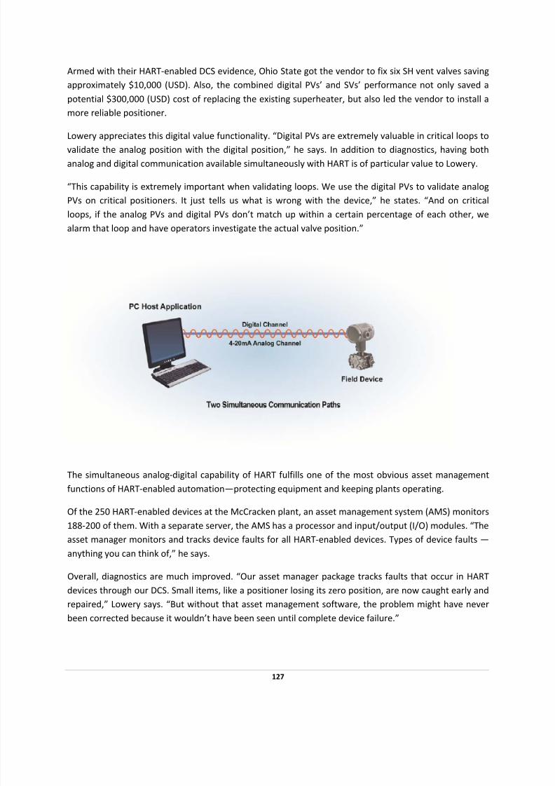
7/28/2019 HART Guide
http://slidepdf.com/reader/full/hart-guide 127/174
7/28/2019 HART Guide
http://slidepdf.com/reader/full/hart-guide 128/174
Correct monitoring, particularly with HART‐enabled instruments, also concerns Lowery, who offers tips
for users. “HART device diagnostics is only as good as the vendor’s device description (DD) file. The more
detailed the DD file, the more diagnostics you’ll have.”
Lowery also suggests insuring that the DCS analog I/O is HART‐enabled. “Using a third‐party solution to
strip out and send HART data via a serial connection will likely prevent using HART digital PVs in a fast changing loop,” he says. Caveat emptor (Let the buyer beware!) is his advice regarding proprietary
functions in HART devices.
“Some vendors tweak a HART DD file to their advantage, so you’ll use their DCS with their HART
devices,” Lowery says. He advises users to make sure all functions are accessible.
“Check that the DD file registered at the HART Communication Foundation is the file that the vendor
distributes. Also, consider joining the Foundation. DD files from the Foundation are tested to be sure
they are compliant to the standards.”
Ohio State’s experience with HART was so positive that, according to Lowery, the university has only scratched the surface of using the protocol. For quality assurance, the power plant’s staff is examining
tracking the drift of the analog PV compared to the digital PV. Also, there’ll be more use of HART device
diagnostic faults in the control strategy. Adding this tracking ensures agreement between the digital PV
and analog PV readings.
Ohio State also plans to evaluate using a field device manager (FDM) for configuring HART devices,
rather than using HART communicators. How will that affect operations? “It will help us catalog devices.
We’re told that if you replace a device, when you plug it in, the DCS will automatically load its tag and
other operating information,” Lowery says.
Finally, through its asset manager, the university will increase fault modeling at McCracken. What part
will HART play? “All HART devices can tell you if there’s a fault,” Lowery says. “We can go to redundant
format automatically.” That’s important, he notes, because the analog PV value could be in error.
128

7/28/2019 HART Guide
http://slidepdf.com/reader/full/hart-guide 129/174
APPLETON PAPER USES HART COMMUNICATION TO
IMPROVE ASSET MANAGEMENT AND SAVES $40,000 ON
WIRING ALONE
PROJECT OBJECTIVES
• Minimize costs for hardware, software, training, spare parts, etc.
• Find a simple, robust system to inform staff about the device health and use that system in
other applications.
• Get a database for configuration, tracking, troubleshooting, etc.
• Obtain access to all instrument/device data.
SOLUTION
• Integrate HART Communication with distributed control system (DCS).
• Install more than 100 HART‐enabled flowmeters, control valves and pressure sensors
throughout the facility.
RESULTS
• Improved instrument configuration and preventive maintenance capabilities
• Lowered operation and maintenance costs
• Accessed multivariable mass flow information
• Realized enhanced device diagnostics
• Improved control‐loop validation
• Increased plant availability
• Enhanced regulatory compliance
• Achieved higher product quality and product yield
129
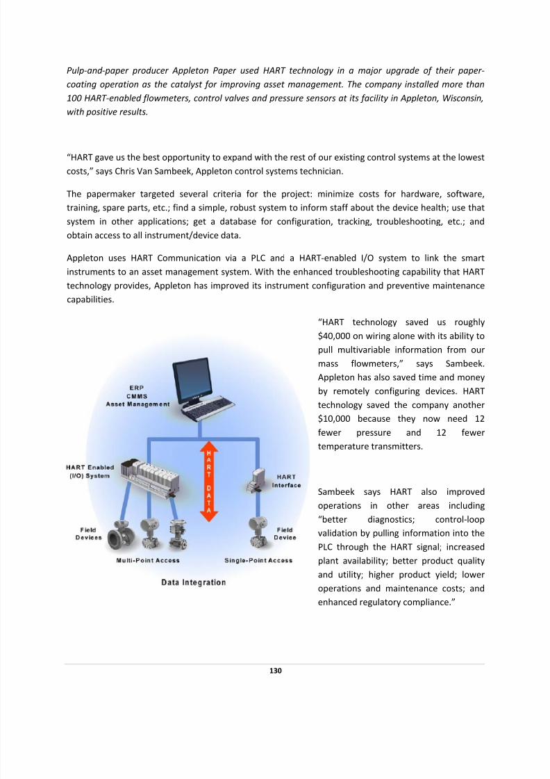
7/28/2019 HART Guide
http://slidepdf.com/reader/full/hart-guide 130/174
130
Pulp‐and ‐ paper producer Appleton Paper used HART technology in a major upgrade of their paper ‐
coating operation as the catalyst for improving asset management. The company installed more than
100 HART ‐enabled flowmeters, control valves and pressure sensors at its facility in Appleton, Wisconsin,
with positive results.
“HART gave us the best opportunity to expand with the rest of our existing control systems at the lowest
costs,” says Chris Van Sambeek, Appleton control systems technician.
The papermaker targeted several criteria for the project: minimize costs for hardware, software,
training, spare parts, etc.; find a simple, robust system to inform staff about the device health; use that
system in other applications; get a database for configuration, tracking, troubleshooting, etc.; and
obtain access to all instrument/device data.
Appleton uses HART Communication via a PLC and a HART‐enabled I/O system to link the smart
instruments to an asset management system. With the enhanced troubleshooting capability that HART technology provides, Appleton has improved its instrument configuration and preventive maintenance
capabilities.
“HART technology saved us roughly
$40,000 on wiring alone with its ability to
pull multivariable information from our
mass flowmeters,” says Sambeek.
Appleton has also saved time and money
by remotely configuring devices. HART
technology
saved
the
company
another
$10,000 because they now need 12
fewer ressure and 12 fewer
temperature t
p
ransmitters.
enhanced regulatory compliance.”
Sambeek says HART also improved
operations in other areas including
“better diagnostics; control‐loop
validation by pulling information into the
PLC through the HART signal; increased
plant availability; better product quality
and utility; higher product yield; lower
operations and maintenance costs; and
7/28/2019 HART Guide
http://slidepdf.com/reader/full/hart-guide 131/174
Finding a new HART smart card that the PLC system could use also helped Appleton. This card allowed
the company to upgrade existing systems with minimal equipment and costs, says Sambeek. “Most of
our existing instruments are HART‐enabled, and the HART cards used are compatible with our existing
control systems.”
Installing an OEM’s HART‐enabled cards into the control PLC platform allowed Appleton to use HART data in both the asset management and control systems. “HART provides additional information not
available to normal analog systems,” Sambeek adds.
“HART has been very effective,” says Sambeek. “We succeeded because the HART Protocol is a better fit
for expansion than other fieldbus technologies.”
131

7/28/2019 HART Guide
http://slidepdf.com/reader/full/hart-guide 132/174
FRASER PAPERS GAINS PREDICTIVE MAINTENANCE EDGE
USING HART VALVE POSITIONING
PROJECT OBJECTIVES
• Connect HART‐enabled valve positioners to a single central computer
• Integrate the newly accessible control valve position data into a predictive maintenance
program
SOLUTION
• HART‐based positioners were linked to a multiplexer using a HART‐enabled interface module
with additional hardware and software
• Import and archive critical data such as valve signatures and operational data
• Operational and diagnostic data coming through the multiplexer were presented to control as
well as device‐managing system software
RESULTS
• The maintenance system provided critical benefits in diagnosing problems during outages as
well as ongoing preventive maintenance benefits
• By avoiding direct PC and handheld calibrator contact at the field level, HART technology
reduced the risk of creating an upset to the process, and also reduced maintenance man‐hours
• Using HART Communication and interfacing digital valve positioner data using a multiplexer
allows a Canadian paper mill to increase efficiency, improve data retrieval and perform
continuous remote diagnostics.
Many end users have realized the benefits of installing HART ‐based control valve positioners and using
HART technology to integrate the positioners with their central computer system. Fraser Papers, a
division of Thurso in Quebec, Canada, standardized its paper mill on HART ‐based positioners as the first
step in a proactive maintenance program.
132

7/28/2019 HART Guide
http://slidepdf.com/reader/full/hart-guide 133/174
133
In June of 2000, the mill wanted to connect
all of its HART‐based positioners to one
central computer. An integration package
consisting of digital products and software solutions allowed the mill to realize the full
benefit of their HART Communication
investment.
The solution was to link all HART‐enabled
positioners to a multiplexer (MUX) using a
HART‐based interface module in addition to
other hardware and software components.
The MUX allows the facility to use computer
software to oversee all of its digital
positioners in the mill and link the
information in an effective device
management system.
Fraser Papers began to realize significant
benefits soon after implementing the HART‐
enabled device management system,
including increased efficiency, easier retrieval of information and continuous remote diagnostics.
“With this system in place, our maintenance technicians can quickly access the device to calibrate and
create electronic maintenance records,” says Mario Leclerc, Fraser Papers instrumentation engineer. “This reduces the risk of creating an upset to the process by avoiding a PC or handheld calibrator
connection to the loop terminals. It also helps us manage man‐hours more efficiently.”
Archiving information (such as valve signatures and continuous operational diagnostics) in maintenance
records allows technicians and maintenance engineers to implement a program of preventive
maintenance on control valves in various sectors of the mill during outages.
Using the dial‐up modem or through the Ethernet, personnel can remotely troubleshoot valves or
request remote assistance from the positioner manufacturer. This helps determine whether to pull the
valve out or simply do minor corrections. The maintenance software can generate step tests of varying
amplitudes, making it easy to validate valve responsiveness online.
Using the online diagnostic capabilities of the positioners, the MUX is able to acquire information
seamlessly. This, in turn, simplifies the implementation of a preventive maintenance program, based on
recorded mean‐time‐between‐failures. These continuous diagnostic values allow the user to determine
if the valve selected is adequate for the service. They can also determine premature trim wear, using the
time‐near‐closed counter.

7/28/2019 HART Guide
http://slidepdf.com/reader/full/hart-guide 134/174
HART‐based technology has opened new doors to help run plants with less downtime while providing a
mechanism to transport critical information from field devices over existing field wiring. The
implementation of a HART system similar to that installed at Fraser Papers is the key element in
implementing a predictive and preventive maintenance program.
134

7/28/2019 HART Guide
http://slidepdf.com/reader/full/hart-guide 135/174
SWEDISH PULP AND PAPER PLANT USES HART
TECHNOLOGY TO IMPROVE PLANT AVAILABILITY
PROJECT OBJECTIVES
• More efficient, effective calibration of field devices
• Higher data availability without the up‐front investment in digital field networks.
SOLUTION
• Enhanced connectivity from control room to instruments
• HART‐enabled devices can be installed anywhere on the 4‐20mA control loop.
RESULTS
• HART technology eliminated a 30‐minute trip to the field for any given device.
• Calibration now done from the safety and comfort of the control room.
HART technology saves trips to the field for improved plant availability. That's what user Jimmy
Andersson, found when he upgraded existing control loops with HART protocol ‐compliant
instrumentation at a pulp and paper plant operated by Vallviks Bruk AB in Söderhamn, Sweden.
As with many users, the Swedish plant needed a way to upgrade its 4‐20mA analog wiring without the
expenditure in full digital field networks. Without effective calibration and data access, plant operations,
asset availability and quality compliance suffer.
The Solution
Handheld or PC‐based HART‐enabled devices/applications that can be installed anywhere on the 4‐
20mA control loop help Andersson save time and reduce costs. “Now I don’t have to go out in the field
to check if a specific instrument is 'alive',” he says. A trip to the field averages about 30 minutes per
device. Multiplying the number of devices accordingly multiplies the savings.
135

7/28/2019 HART Guide
http://slidepdf.com/reader/full/hart-guide 136/174
Benefits and Outcome
According to Andersson, HART technology improves operations, specifically enhancing plant availability
and quality compliance. “The greatest benefit is that I can calibrate instruments from inside the control
room,” he says, which is “a lot safer and more comfortable than doing it out in the field.”
HART Communication has reduced configuration and set‐up time as well. “Before HART we had to
calibrate the instruments out in the process. Now we can do it right where the signal goes into the
control system,” Andersson says. After initial implementations, the plant's plans with HART technology
expanded to the start‐up of a new turbine.
According to Andersson, using HART technology for data including instrument calibration has improved
the performance of controls for improved plant operations, asset availability and quality.
136
7/28/2019 HART Guide
http://slidepdf.com/reader/full/hart-guide 137/174
BRAZILIAN STEEL PLANT USES HART COMMUNICATION
TO REDUCE DATA RETRIEVAL TIME
PROJECT OBJECTIVES
• Faster, more complete access to data
• More data visibility for process management and instrument maintenance
• A cost‐effective solution for an existing plant
SOLUTION
• HART‐enabled control, software and asset management systems
• Handheld communications devices (Models 275 and 375).
• PC Anywhere for remote off ‐site access.
RESULTS
• More data available to personnel on off ‐hours—including technicians at home—to assist at‐
plant personnel as needed.
• Time and money savings through faster configuration and modifications.
• Changing a range in a traditional analog setting once took an hour; it now takes five minutes
with HART technology.
HART technology helped engineers and technicians at a COSIPA plant in Sao Paulo, Brazil, more
effectively configure
and
access
data
to
better
manage
field
devices
across
the
automation
network.
In
fact, some tasks that once took an hour to complete now take five minutes.
137

7/28/2019 HART Guide
http://slidepdf.com/reader/full/hart-guide 138/174
What Was Needed
Personnel at this existing plant needed faster data access for process management and instrument
maintenance.
The Solution
HART‐enabled process control and asset management systems plus handheld communications devices
(Models 275 and 375).
Benefits and Outcome
To calculate the cost savings in time and money realized by the COSIPA plant, we must first note that in
Brazil a technician earns the equivalent of $10 USD per hour. Using HART Communication saves the
plant about one hour on each device and there are 200 devices in the plant.
According to user Marcos Martins, when with traditional 4‐20mA wiring, “I spent one hour just to
change a range. I spend five minutes to do this same task with AMS.” Equipped with HART
Communication, the asset management system provides the user with instant visibility.
138
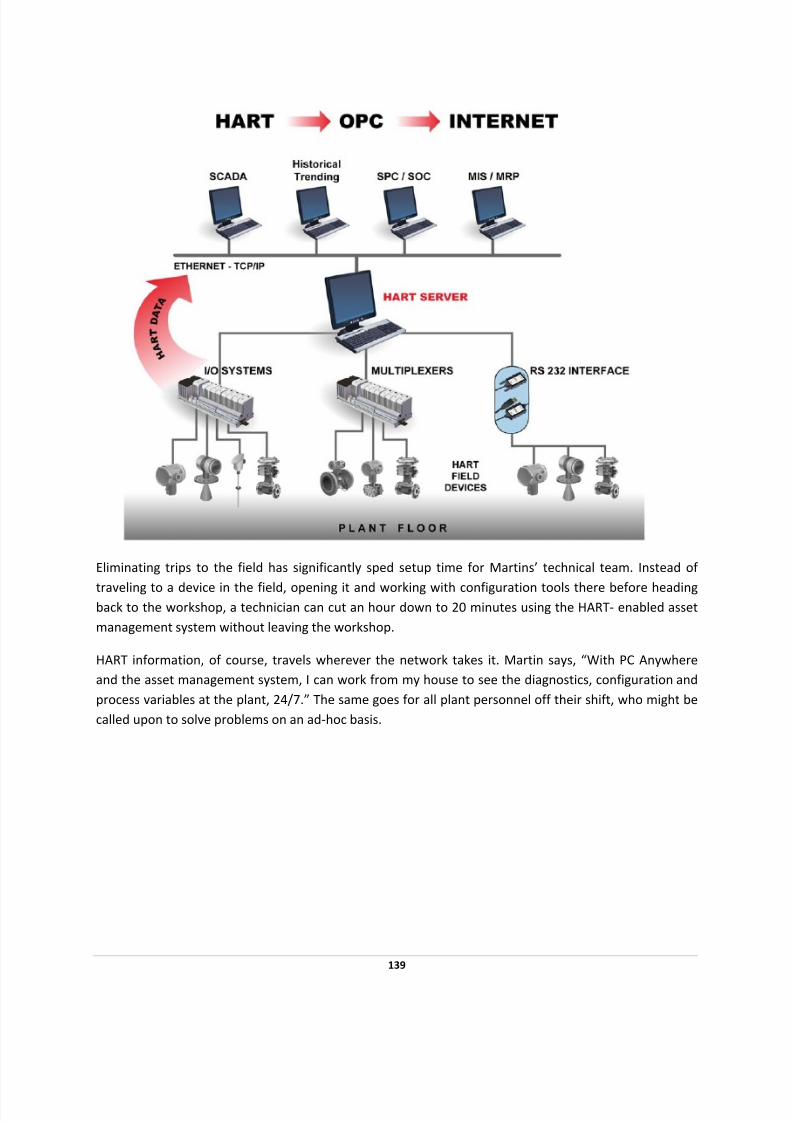
7/28/2019 HART Guide
http://slidepdf.com/reader/full/hart-guide 139/174

7/28/2019 HART Guide
http://slidepdf.com/reader/full/hart-guide 140/174
AECOM CANADA USES HART COMMUNICATION
TO KEEP WATERWAYS CLEAN
PROJECT OBJECTIVES
• Prevent unplanned discharges of sewage to keep waterways clean
• Avoid fines that result from tightening regulations
• Find the most cost‐effective and accurate system so the system can be widely replicated.
SOLUTION
• HART‐enabled remote terminal unit and instrumentation at each site
• HART communications card and IP‐addressable Ethernet data radio at each site for remote
access
• Standard single‐wire, single‐bus connection for a faster, more accurate multi‐variable data path
to magnetic flowmeters and pressure transmitters
RESULTS
• Full access to multiple variables from field instruments on a single wire.
• Significant time savings over the use of separate 4‐20mA wiring.
• A reliable defense against potential 100s of thousands in regulatory fines.
• Future‐proofing: Engineers can change their control strategy without running new wires or re‐
wiring their systems.
• With WirelessHART technology solutions now shipping, future installations will reap additional
savings by eliminating physical wiring labor, time and cost.
Few cities use modern technology to monitor and detect leaks, particularly as sewerage travels across
waterways. Facing tightening environmental and regulatory requirements, AECOM Canada, Ltd., in
Winnipeg, Manitoba, designed and created first ‐case system using HART Technology to address the
issue.
140

7/28/2019 HART Guide
http://slidepdf.com/reader/full/hart-guide 141/174
To prevent unplanned discharges—leaks—in its sewage system, particularly at river crossings, one city in
Manitoba, Canada, called upon engineering firm AECOM Canada, Ltd., Winnipeg, to design and test a
first‐of ‐a‐kind monitoring and detection system. HART technology proved critical in speeding
implementation and providing the flexibility to reconfigure the system without the time or expense of
physical rewiring,
The particular challenge was to monitor force‐main sewer lines at river crossings, where gravity cannot
lift material through lines and low‐pressure pumping (10 to 15 psi) is a common solution. Despite
tightening environmental regulations, engineers could find no existing solutions. Most cities rely on
visual inspection—a poor substitute for technology because contamination can leak for weeks before a
problem is detected, damaging waterways and drawing regulatory fines.
Unfortunately, "very few" cities have applied modern monitoring solutions because, says AECOM's Kent
McKean, senior automation designer, and a viable commercial solution couldn't be found.
The Solution
McKean's team used a basic architecture involving instrumentation connected to a remote terminal unit
(RTU). The RTU was equipped with an IP‐addressable Ethernet data radio at each site to remotely access
site data and a HART communications card.
McKean and team decided that for test installations, they would specify a system that would “give us
flexibility, perhaps more flexibility than what we actually needed” because there was no way to
“definitively predict” which system design would work best.
In mid‐2007, the first test installation came online using magnetic flowmeters sending data to the RTU
to be totalized and compared with data points coming in eight‐ to 10‐hour increments. The HART
protocol would prove its value in providing that flexibility when McKean's team decided on a "change in
philosophy" that would require reconfiguring the system to provide instantaneous, real‐time data in
addition to the existing totalization strategy.
141

7/28/2019 HART Guide
http://slidepdf.com/reader/full/hart-guide 142/174
This change "was easily accomplished because we had selected HART," says McKean. Instead rewiring
and reconfigure physical equipment, he says, "HART technology and the system's software put all of the
variables we needed at our fingertips." The change in data handling led to an increase in resolution from
10 to 15 liters per second, to one or two liters per second.
Late in the summer of 2008, the AECOM team installed a second test‐site system using the same
strategy but switching from flowmeters to smaller, easier‐to‐install pressure transmitters measuring the
pressure inside and also in the interstitial space. This enabled users to pinpoint the location of a leak as
well as its failure mode, such as whether the exterior or interior pipe has failed. This solution was less
intrusive and provided easier, safer access; reduced maintenance trips by several hours; and slashed
system cost from roughly $500,000 to between $30,000 and $50,000 per crossing, according to McKean.
Benefits and Outcomes
HART technology provided “much higher accuracy and resolution” than 4‐20mA analog wiring while
requiring no hardware and only minor software changes to accommodate the upgrade from totalization
to instantaneous data monitoring. The same benefits can, in turn, reduce the cost of future upgrades."If
we had gone with a non‐HART solution or a non‐databus solution, we would have been very limited in
the data that we could have gotten,” McKean says. “We would have had to use a separate radio or data
channel for each variable that we may need, or we would have had to change things on the fly as we
were developing.”
“If we were to implement this system today, we would utilize WirelessHART,” McKean says.
142

7/28/2019 HART Guide
http://slidepdf.com/reader/full/hart-guide 143/174
DETROIT WATER AND SEWERAGE DEPLOYS
HART TECHNOLOGY TO IMPROVE CUSTOMER
SATISFACTION
PROJECT OBJECTIVES
• Redundant metering systems would register different volumes, which led to billing disputes.
SOLUTION
• Modernize and unifying the point of sale metering system and transmit the data in real‐time to
DWSD and every wholesale customer.
• Use existing analog instrumentation and the skill set of our technicians while providing us the
benefits of a state‐of ‐the‐art digital and paperless metering system.
• Distribute the totalization function to a lower, HART‐enabled smart device level, instead of the
traditional PLC/RTU device.
RESULTS
• Complaints about low water pressure have been virtually eliminated since a majority of these
complaints have been attributed to faulty regulating valves operated by our wholesale
customers.
• Safety has also been improved since the need to enter the OSHA regulated confined space of
the underground metering facilities for troubleshooting purposes has been greatly reduced or
eliminated..
• Metering data obtained from the HART‐instrument is communicated and stored in digital form,
eliminating paper‐based recordings.
• A digital packet radio network, which functions like a wireless intranet, is used to “carbon copy”
all metering data to redundant data historians and to SCADA PCs that DWSD provided to each
customer.
The need for having redundant metering systems has been eliminated since the same metering data
reported from our HART ‐based instruments to the RTU, is “carbon copied” every five minutes directly
143
7/28/2019 HART Guide
http://slidepdf.com/reader/full/hart-guide 144/174
from the on‐site RTU to DWSD as well as to our wholesale customers within a few seconds – we provided
a SCADA PC to each wholesale customer. This has already contributed to improved customer satisfaction.
“HART has served us so well by utilizing all of our existing plant assets.”
By Dennis L. Green, P.E.
Head Water Systems Engineer
Detroit Water and Sewerage Department (DWSD)
The Detroit Water & Sewerage Department (DWSD) is the third largest water and wastewater utility in
the United States. DWSD provides services to nearly 1 million Detroit residents and, on a wholesale
basis, to over 3 million suburbanites living in the surrounding areas.
To determine water consumption at the point‐of ‐sale, we had installed metering systems. Our point‐of ‐sale metering systems included a variety of traditional instruments such as mechanical meters, venturis,
orifice systems, magnetic flowmeters and chart recorders. Likewise, our wholesale customers had
installed their own point of purchase metering systems, acting in parallel, to make their own
measurements. Very often, the redundant metering systems would register different volumes, which led
to billing disputes.
The solution was modernizing and unifying the point of sale metering system and transmitting the data
in real‐time to DWSD and every wholesale customer. An essential and critical part of the multi‐million
dollar modernization project was implementing an automatic meter reading/supervisory control and
data
acquisition
(AMR/SCADA)
system
that
relies
on
the
HART
global
standard
to
deliver
consistent,
reliable data on system performance.
The innovative application of HART technology enabled us to use existing analog instrumentation and
skills set of our technicians while providing us the benefits of a state‐of ‐the‐art digital and paperless
metering system.
Today, the HART standard based digital metering system has not only improved the reliability of our
water metering operations but has also provided our customers with greater satisfaction by virtually
eliminating billing disputes caused by metering problems. As a bonus, our new HART based smart
instruments also provide additional flexibility to make on‐line configuration changes including
calibration, perform calculations and support real‐time remote diagnostics.
DWSD Services
With an operating budget of over $350 million, DWSDs’ services extend well beyond the Detroit city
limits to an 8‐county area of more than 1,000 square miles including approximately 43% of Michigan’s
population. DWSD, which is a branch of the City of Detroit government, employs about 3,200 persons
and has the fifth lowest combined water and sewerage rates per month amongst the 20 most populated
144

7/28/2019 HART Guide
http://slidepdf.com/reader/full/hart-guide 145/174
cities in the United States. DWSD operates five water treatment plants pumping an average of 655
million gallons of clean drinking water each day, peaking at 1.5 billion gallons per day.
DWSD serves about 90 wholesale customers representing about 137 suburban communities via nearly
300 underground metering facilities. Figure 1 illustrates one such underground metering facility. These
metering facilities typically include flow and pressure measuring instruments, valves and actuators to monitor and control the flow of water to the wholesale customer.
Akin to custody transfer stations, these metering systems, which include approximately 750 smart
instruments, provide valuable inputs to detect and compute water usage, and hence billable sale to
each wholesale customer. Since the metering systems are critical for billing purposes, we often refer to
the meters as our point‐of ‐sale “cash registers”.
Figure 1. Typical underground metering facility
Need For a New Metering System
Prior to implementation of the AMR/SCADA project, the metering facilities included a variety of traditional instruments such as mechanical meters, venturis, orifice systems, differential pressure
transmitters, sonic meters, magnetic flowmeters and chart recorders. The existing metering facilities
used no electronics with the mechanical meters, and all other instruments used chart recorders and
mechanical pulse totalizers.
145

7/28/2019 HART Guide
http://slidepdf.com/reader/full/hart-guide 146/174
Thus, recording of all metering data was paper‐based and collected manually bi‐monthly or weekly by
human meter readers. Various instrumentation companies including Smar, Endress+Hauser, and ABB
manufactured these instruments.
By the mid‐1990s, however, many of our wholesale customers had concerns over their water
consumption data. They elected to install their own point‐of ‐purchase “cash registers” to collect more frequent readings and validate their DWSD water bills. The point‐of ‐purchase “cash registers” included
redundant metering systems measuring the same water flow and pressure as DWSD recorded on our
paper chart recorders. Quite often, the two metering systems disagreed over the water consumption
data.
Moreover, the resolution of the chart records was insufficient to prove one party’s assertions over the
other, the simple odometer‐type totalizers provided no profiles of the consumption data between visits
by our meter readers, and all humans make occasional mistakes when recording data. The
disagreements over a mutually acceptable set of measurements resulted in billing disputes, customer
dissatisfaction and loss of thousands of dollars in revenues.
Acquiring Leading Edge Technology to Improve Customer Satisfaction
DWSD decided it must modernize and unify the point‐of ‐sale metering system and improve customer
satisfaction. Our goal was to eliminate dispute‐causing devices such as chart recorders and mechanical
totalizers and replace them with a digital and paperless metering system specifically to:
1) Improve dependability, accuracy and confidence in the metering data by recording meter
readings every 5 minutes – Objectives were ending the practice of our wholesale customers
installing their own redundant metering equipment that often disagreed with DWSD’s, leading
to
billing
disputes.
Failure
of
any
single
component
of
the
system
must
not
disrupt
system
performance, any recording of data, or any calibration work of the meter technicians –
excepting the one failed meter register.
2) Preserve metering data integrity – Data consistency must be maintained throughout the
system. The same consumption data must be concurrently provided to DWSD as well as each
wholesale customer. In addition, there must be opportunities to recover data when failures
occur.
3) Archive 10‐years of meter data in redundant historian systems for efficient storage and
retrieval, engineering analysis and process improvement.
4) Provide an intuitive, easy‐to‐use, user interface to assist our staff in the setup and calibration
of the meters while automatically documenting the data for certification of our “cash register” ‐
the billing meter. Minimal reliance on paperwork to share information throughout the system
by storing the calibration reports in the database of the AMR/SCADA historian.
5) Reduce operating costs of the Meter Operations Division by standardizing on the equipment
used and by controlling software revisions.
146

7/28/2019 HART Guide
http://slidepdf.com/reader/full/hart-guide 147/174
To get the maximum out of the investment in the meters, they are usually sized for predicted future
consumption that may or may not develop. By using peak hourly consumption data, rather than
maximum meter capacity, a more equitable rate formula can be established based on peak
consumption. In addition, the range of the instruments can be set based on actual peak demands to
improve the accuracy of the instruments as the technicians have a basis for making their range
adjustments as consumption increases or declines over the years.
DWSD is owned and operated by The City of Detroit and has had to resist frequent regionalization
attempts by some of its suburban customers. Being a rate funded utility and having to defend those
rates annually, the project risk and overall installed costs were of paramount importance to our
management. Any proposed solution incorporating the latest and greatest technology had to address
risks and costs satisfactorily and, in addition, had to address the risk of failure. hat is, a backup plan had
to be developed and approved by our management in case the proposed solution did not function as
planned.
Demand Based Rate Model
In addition to the above described project objectives, Stephen Gorden, former director of DWSD, had
expressed a desire to use the modernization project for restoring DWSD’s traditional position as an
industry leader. His vision was to introduce a demand based water usage rate model in the water utility
industry. More specifically, he wanted a system that would support the development of a demand based
rate model, similar to the model(s) used by the electric utility industry, where there is an infrastructure
charge based on peak load and a consumption charge for total usage. This requirement implied that the
new metering system was capable of performing and preserving multiple reads every hour to identify
the peak hourly demand.
Developing a New
AMR/SCADA
System
by
Leveraging
HART
Technology
Before launching the project to modernize the point‐of ‐sale metering system, we had recognized the
ability to calibrate instruments remotely and on‐line as an important function to improve reliability and
confidence of metering data. By 1996, we were well underway to implement an instrument upgrade
project to incorporate the HART standard into many of our existing 4‐20mA instruments. The HART
based smart instruments would facilitate calibration and at the same time preserve our investment.
During 1996‐97, DWSD developed and implemented a pilot‐scale version of the AMR/SCADA system to
modernize the point‐of ‐sale metering system. The pilot project was expanded (1999‐2002) to a $10
million major infrastructure upgrade. Figure 2 illustrates a schematic diagram of DWSD’s AMR/SCADA
system. The AMR/SCADA system utilizes a packet radio network of personal computers, programmable
logic controllers (PLCs), and remote terminal units (RTUs). The system relies on the power of HART
communication to deliver consistent, reliable data on system performance.
147

7/28/2019 HART Guide
http://slidepdf.com/reader/full/hart-guide 148/174
Figure 2. Schematic of DWSD’s AMR/SCADA system
The decision to adopt the HART standard for integrating our meters was relatively simple since we
already had in‐house experience. Perhaps, more importantly, HART was evaluated to be the only stable
and reliable technology available at the time which would enable us to integrate a vast array of diverse
field devices and technologies including mechanical, venturi, orifice, magnetic and sonic meters into a
single digitally networked system.
Other field device technologies such as FOUNDATION™ fieldbus and Profibus‐DP were still evolving,
costly, and radically different and incompatible with our existing smart instrumentation. Use of these
other technologies would have substantially increased the project risk and the total installed costs.
HART technology was an ideal fit for our requirements since it delivered the benefits of an all digital
system at a minimized incremental investment for the modernization project. Most of our existing
instrumentation was HART‐capable, which enabled us to use the existing wiring. The project easily gained management approval mainly due to our ability to default back to the existing analog‐chart‐
recorder system in case of difficulties.
Maintaining the Look and Feel of Mechanical Meters to Ease Transition
At the start of the pilot project, our technicians and customers indicated a strong preference for
mechanical meter‐type totalizers at each metering site. To improve their comfort level with the
148
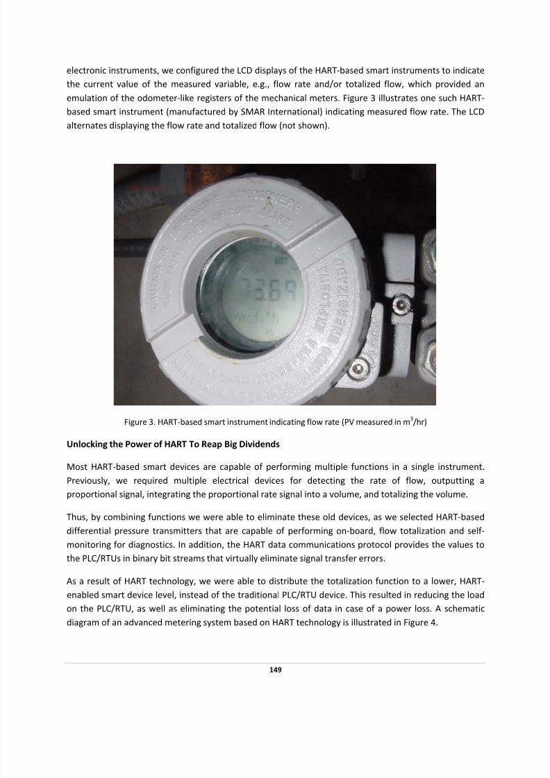
7/28/2019 HART Guide
http://slidepdf.com/reader/full/hart-guide 149/174
electronic instruments, we configured the LCD displays of the HART‐based smart instruments to indicate
the current value of the measured variable, e.g., flow rate and/or totalized flow, which provided an
emulation of the odometer‐like registers of the mechanical meters. Figure 3 illustrates one such HART‐
based smart instrument (manufactured by SMAR International) indicating measured flow rate. The LCD
alternates displaying the flow rate and totalized flow (not shown).
Figure 3. HART‐based smart instrument indicating flow rate (PV measured in m3/hr)
Unlocking the Power of HART To Reap Big Dividends
Most HART‐based smart devices are capable of performing multiple functions in a single instrument.
Previously, we required multiple electrical devices for detecting the rate of flow, outputting a
proportional signal, integrating the proportional rate signal into a volume, and totalizing the volume.
Thus, by combining functions we were able to eliminate these old devices, as we selected HART‐based
differential pressure transmitters that are capable of performing on‐board, flow totalization and self ‐
monitoring for diagnostics. In addition, the HART data communications protocol provides the values to the PLC/RTUs in binary bit streams that virtually eliminate signal transfer errors.
As a result of HART technology, we were able to distribute the totalization function to a lower, HART‐
enabled smart device level, instead of the traditional PLC/RTU device. This resulted in reducing the load
on the PLC/RTU, as well as eliminating the potential loss of data in case of a power loss. A schematic
diagram of an advanced metering system based on HART technology is illustrated in Figure 4.
149

7/28/2019 HART Guide
http://slidepdf.com/reader/full/hart-guide 150/174
150
LEGEND:Yellow = Differential Pressure Cells
Green = Pressure Transmitters
Purple = HART Data Communic ations on Instrument Loop
Pink = AC Power to Solenoid of 4-Way Cross-Over Valve
Gray = Actuator & 4-Way Cross-Over Valve
Tan = RTU, Metricom Radio & DF/1 Data Comm unications
Dashed = Present in Some Meter Pits, or in Separate Pit
Orange = Limit Switches on Valve
Meter Pit
PT
Ac tuato r & Li mi t Sw itch es ,Four-Way Valve with Solenoid
Limit Switch
Prepared by: Cliff MontgomeryFile = Typical Meter.vds
Rhythm Technologies, LLC
Above Groun d Control Cab in et
Battery , Chargers
& Power Supplies
Coax & Power Surge Suppressors,
Open Door Alarm, High Sump Alarm ,
AC P ow er Fai l A la rm , St ri p Heate rs
PLC/RTU
DPDP
RADIO
Sump &
Sump Pump
LEGEND:
PTPT
PRV
Figure 4. Schematic of a Venturi/Orifice meter based on HART technology
The flow totalization data is actually retained in the memory of each HART‐enabled smart instrument
even when there is a loss of power. As a matter of fact, our system survived the massive power failure of
August 14, 2003 that occurred in the Northeastern part of the United States with little or no loss data.
This was an unrehearsed critical test since it occurred during our peak‐revenue summer months.
As an additional benefit, by executing the totalization function at the HART device level, we were able to
obtain much more accurate totalization data. The HART device integrates totalization data sampled far
more frequently than the PLC/RTU. As a result, the totalization values are more accurate.
The sampling frequency of the microprocessor based instrument approaches the Nyquist criteria for
integrating the fluctuations of the water flowing through venturis and orifices that can reach to audio
frequencies. The best of the communications protocols for instrumentation are substantially slower
resulting in random sampling errors that although small relative to instantaneous flow, accumulate in the totalized flow far beyond acceptable limits.
With the need to read instantaneous flow for range switching combined with the necessity of totalizing
flow in the instrument, this project would have been far more costly without the HART ability to read
multiple functions in a single smart instrument. By shifting the calculations to the smart instruments, we
freed the PLC/RTU to perform other tasks, such as device monitoring for all HART devices located at the
underground metering facilities, and storing 31 days of metering data collected at 5‐minute intervals.
7/28/2019 HART Guide
http://slidepdf.com/reader/full/hart-guide 151/174
We were also able to maintain greater accuracy of metering data throughout our water‐distribution
system, largely due to HART’s ability to preserve the full accuracy of the measuring element in a digital
format. The improved accuracy has directly resulted in increased revenues, since our old mechanical
meter based cash registers often erred in favor of our wholesale customers.
The need for having redundant metering systems has been eliminated since the same metering data reported from our HART‐based instruments to the RTU, is “carbon copied” every five minutes directly
from the on‐site RTU to DWSD as well as to our wholesale customers within a few seconds – we
provided a SCADA PC to each wholesale customer. This has already contributed to improved customer
satisfaction.
Our wholesale customers can access metering data received from their respective meters directly rather
than receiving it through our headquarters. This assures our wholesale customers that DWSD is not
adjusting or manipulating their metering data.
HART enables the master device such as the PLC/RTU to automatically query each smart instrument to
detect the types and brands of HART‐based instruments on the network. Instrument data such as their
brand type and serial numbers are collected each day for a permanent record of each instrument. HART
enables the detection and documentation of instrument changes that invalidate calibration.
Metering data received from failed instruments is not logged or used in any billing computation.
Previously, a failed analog instrument sometimes produced bogus signals thereby corrupting the meter
readings.
HART‐enabled remote monitoring, calibration, and validation of metering systems have contributed to
improved safety and greater customer satisfaction. Our technicians can now perform these tasks on
any
HART‐
based
smart
device
in
the
comfort
of
their
office.
For
example,
pause
and
resume
signals
can
be sent remotely to these instruments for series connected meters for range switching. With improved
diagnostics, our technicians can quickly detect and repair failures in our water distribution system.
Complaints about low water pressure have been virtually eliminated since a majority of these
complaints have been attributed to faulty regulating valves operated by our wholesale customers. Our
system now monitors these valves and reports any problems directly to the customers.
Safety has also been improved since the need to enter the OSHA regulated confined space of the
underground metering facilities for troubleshooting purposes has been greatly reduced or eliminated.
Previously, there have been fatal accidents in these underground metering facilities.
Metering data obtained from the HART‐instrument is communicated and stored in digital form,
eliminating paper‐based recordings. A digital packet radio network, which functions like a wireless
intranet, is used to “carbon copy” all metering data to redundant data historians and to SCADA PCs that
DWSD provided to each customer.
151
7/28/2019 HART Guide
http://slidepdf.com/reader/full/hart-guide 152/174
The DWSD meter technicians use radio linked laptop computers for configuration and direct entry of
calibration data, eliminating paper and copying errors. By analyzing the real‐time and historical data
collected, we have improved efficiency by revising operating procedures.
HART has served us so well by utilizing all of our existing plant assets. Other fieldbus technologies have
matured considerably since 1996, when DWSD began piloting our system. Nevertheless, we would still use HART, even if the project were starting today. Other newer fieldbus technologies would have cost us
at least twice as much, since we would have had to discard a majority of our existing instruments.
Looking ahead, DWSD is developing another SCADA system for controlling our treated water
transmission system and wastewater collection system, which includes new sewer meters. Since many
instruments included in the SCADA system are also HART‐capable, we would like to tie them in into our
water metering AMR/SCADA system.
2003 HART Plant of the Year
152
7/28/2019 HART Guide
http://slidepdf.com/reader/full/hart-guide 153/174
HART COMMUNICATION SUPPORTS SAFER
SEWER SYSTEM
PROJECT OBJECTIVES
• Improve measurement by using temperature compensated devices and perform installation
calibration in an explosion‐proof area.
SOLUTION
• MMSD installed more than 200 level transmitters with HART‐based interfaces in manholes,
which are Class 1, Division 1‐rated areas. MMSD installed the HART instruments because the
level instrumentation in place was not temperature compensated.
• The HART dual functionality (analog plus digital) allows seamless operation of the system while
the instrument is being interrogated and updated.
RESULTS
• HART‐enabled devices saved money for MMSD and those savings coupled with the technology’s
flexibility, reliability and field ruggedness are why HART devices are used throughout
Milwaukee’s sewage‐treatment system.
• The installation reduces the time to calibrate the instrument and eliminates the need to enter the manhole
To keep its own process competitive, the Milwaukee Metropolitan Sewerage District (MMSD) installed
more than 200 level transmitters with HART ‐based interfaces in manholes, which are Class 1, Division 1‐
rated areas. MMSD installed the HART instruments because the level instrumentation in place was not
temperature compensated.
HART technology’s analog functionality allowed an intrinsically safe barrier and installation calibration in
an explosion‐proof area. “The collection‐system manholes are typically entered once‐a‐year for
calibration checks,” explains Eugene Moe, senior instrumentation and control engineer for Earth Tech
Inc. in Sheboygan, Wisconsin. Earth Tech was part of a joint venture team hired to manage MMSD’s
operations.
153
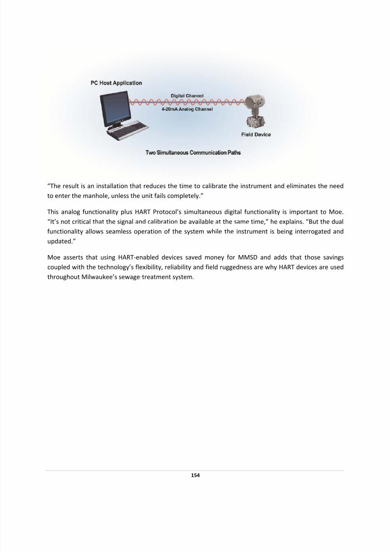
7/28/2019 HART Guide
http://slidepdf.com/reader/full/hart-guide 154/174
“The result is an installation that reduces the time to calibrate the instrument and eliminates the need
to enter the manhole, unless the unit fails completely.”
This analog functionality plus HART Protocol’s simultaneous digital functionality is important to Moe.
“It’s not critical that the signal and calibration be available at the same time,” he explains. “But the dual
functionality allows seamless operation of the system while the instrument is being interrogated and
updated.”
Moe asserts that using HART‐enabled devices saved money for MMSD and adds that those savings
coupled with the technology’s flexibility, reliability and field ruggedness are why HART devices are used
throughout Milwaukee’s sewage‐treatment system.
154

7/28/2019 HART Guide
http://slidepdf.com/reader/full/hart-guide 155/174
PERSIAN GULF COMPANY USES HART COMMUNICATION
TO IMPROVE WATER CONVERSION PROCESS
PROJECT OBJECTIVES:
• Get better resolution and accuracy from measurement devices
• Save time and labor in calibration and troubleshooting.
• Achieve best functionality of asset management
• Obtain access to all instrument/device data
SOLUTION:
• Install more than 2,000 HART‐enabled devices.
RESULTS:
• Saved time and labor in calibration and troubleshooting during pre‐commissioning, startup and
commissioning.
• Analog signal provided the fastest and best overall scan period
• Digital signal helped to quickly calibrate and troubleshoot devices including control valve
positioner feedback
• HART technology’s interoperability capability allowed integration of asset management system
and devices from different manufacturers
• Remote troubleshooting of device status reduced time needed to check devices in the field
• No disputes because HART is proven to be a very reliable platform
Saline Water
Conversion
Corporation
(SWCC)
used
HART
technology
in
a major
re
‐instrumentation
project as the catalyst for improving asset management. “Despite the size of this mega project, HART
technology helped us at the core achieving best resolution and accuracy of the data,” says T. Veeresh
Prasad, Yokogawa Engineering.
155
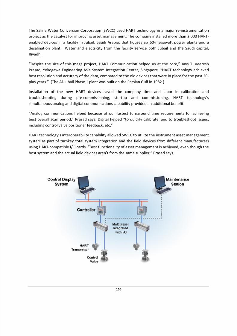
7/28/2019 HART Guide
http://slidepdf.com/reader/full/hart-guide 156/174
The Saline Water Conversion Corporation (SWCC) used HART technology in a major re‐instrumentation
project as the catalyst for improving asset management. The company installed more than 2,000 HART‐
enabled devices in a facility in Jubail, Saudi Arabia, that houses six 60‐megawatt power plants and a
desalination plant. Water and electricity from the facility service both Jubail and the Saudi capital,
Riyadh.
“Despite the size of this mega project, HART Communication helped us at the core,” says T. Veeresh
Prasad, Yokogawa Engineering Asia System Integration Center, Singapore. “HART technology achieved
best resolution and accuracy of the data, compared to the old devices that were in place for the past 20‐
plus years.” (The Al‐Jubail Phase 1 plant was built on the Persian Gulf in 1982.)
Installation of the new HART devices saved the company time and labor in calibration and
troubleshooting during pre‐commissioning, startup and commissioning. HART technology’s
simultaneous analog and digital communications capability provided an additional benefit.
“Analog communications helped because of our fastest turnaround time requirements for achieving
best overall scan period,” Prasad says. Digital helped “to quickly calibrate, and to troubleshoot issues,
including control valve positioner feedback, etc.”
HART technology’s interoperability capability allowed SWCC to utilize the instrument asset management
system as part of turnkey total system integration and the field devices from different manufacturers
using HART‐compatible I/O cards. “Best functionality of asset management is achieved, even though the
host system and the actual field devices aren’t from the same supplier,” Prasad says.
156

7/28/2019 HART Guide
http://slidepdf.com/reader/full/hart-guide 157/174
HART‐based HMIs provided greater accuracy and were used to calibrate most devices, adds Prasad. And,
rather than running to the field to check devices’ troubleshooting status, the staff now uses the asset
management system to crosscheck that status.
“The result is less disputes—or no disputes,” Prasad says. “HART is a very reliable platform for fastest
response requirements of control and automation safety‐instrumented systems. It competes with all other buses, all the time.”
157
7/28/2019 HART Guide
http://slidepdf.com/reader/full/hart-guide 158/174
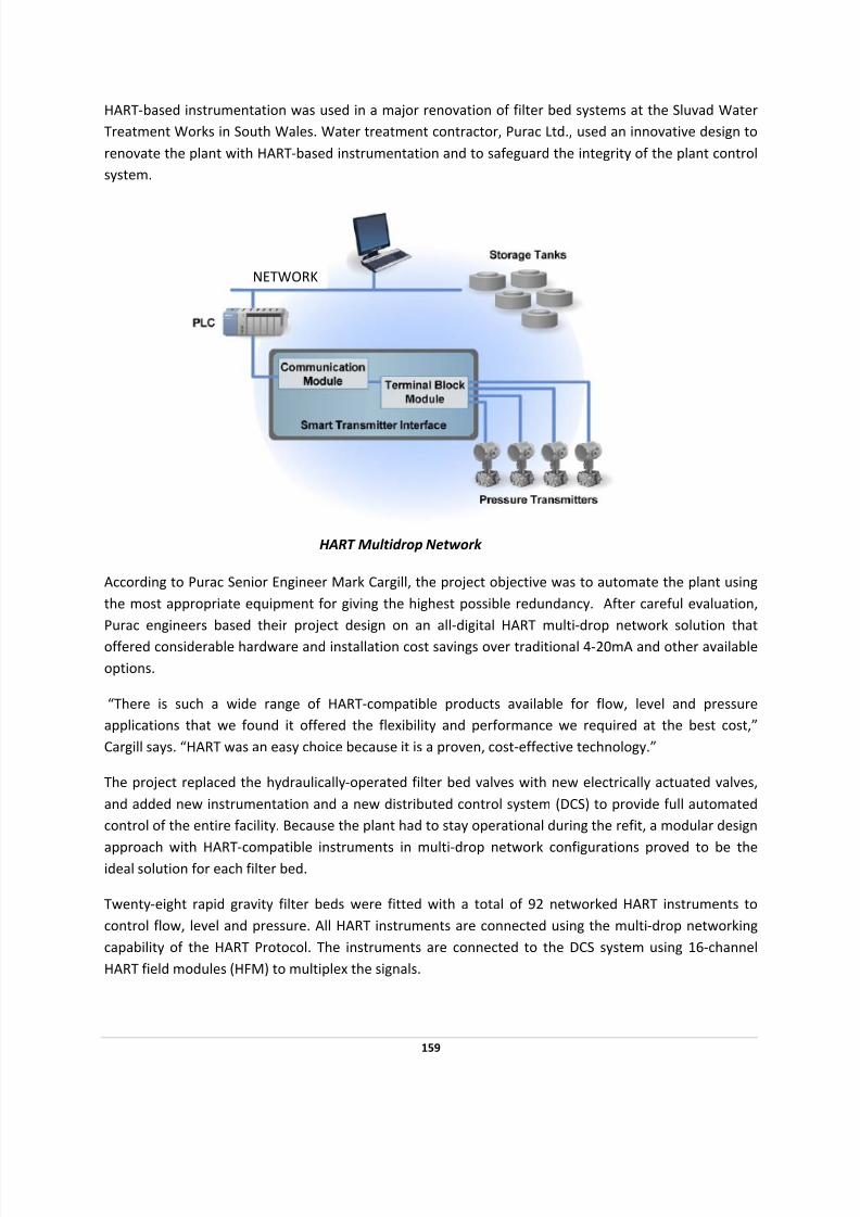
7/28/2019 HART Guide
http://slidepdf.com/reader/full/hart-guide 159/174
HART‐based instrumentation was used in a major renovation of filter bed systems at the Sluvad Water
Treatment Works in South Wales. Water treatment contractor, Purac Ltd., used an innovative design to
renovate the plant with HART‐based instrumentation and to safeguard the integrity of the plant control
system.
NETWORK
HART Multidrop Network
According to Purac Senior Engineer Mark Cargill, the project objective was to automate the plant using
the most appropriate equipment for giving the highest possible redundancy. After careful evaluation,
Purac engineers based their project design on an all‐digital HART multi‐drop network solution that
offered considerable hardware and installation cost savings over traditional 4‐20mA and other available
options.
“There is such a wide range of HART‐compatible products available for flow, level and pressure
applications that we found it offered the flexibility and performance we required at the best cost,”
Cargill says. “HART was an easy choice because it is a proven, cost‐effective technology.”
The project replaced the hydraulically‐operated filter bed valves with new electrically actuated valves,
and added new instrumentation and a new distributed control system (DCS) to provide full automated
control of the entire facility. Because the plant had to stay operational during the refit, a modular design
approach
with
HART‐
compatible
instruments
in
multi‐
drop
network
configurations
proved
to
be
the
ideal solution for each filter bed.
Twenty‐eight rapid gravity filter beds were fitted with a total of 92 networked HART instruments to
control flow, level and pressure. All HART instruments are connected using the multi‐drop networking
capability of the HART Protocol. The instruments are connected to the DCS system using 16‐channel
HART field modules (HFM) to multiplex the signals.
159
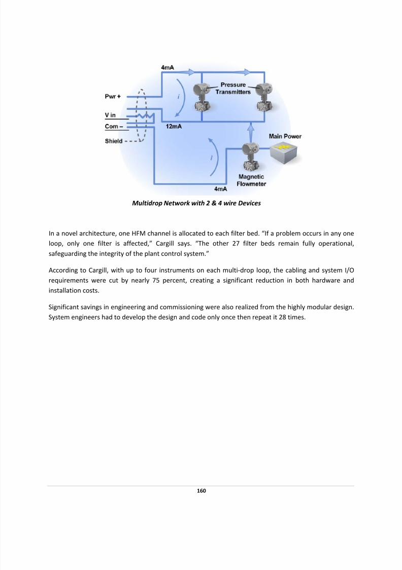
7/28/2019 HART Guide
http://slidepdf.com/reader/full/hart-guide 160/174
Multidrop Network
with
2 &
4 wire
Devices
In a novel architecture, one HFM channel is allocated to each filter bed. “If a problem occurs in any one
loop, only one filter is affected,” Cargill says. “The other 27 filter beds remain fully operational,
safeguarding the integrity of the plant control system.”
According to Cargill, with up to four instruments on each multi‐drop loop, the cabling and system I/O
requirements were cut by nearly 75 percent, creating a significant reduction in both hardware and
installation costs.
Significant savings in engineering and commissioning were also realized from the highly modular design.
System engineers had to develop the design and code only once then repeat it 28 times.
160

7/28/2019 HART Guide
http://slidepdf.com/reader/full/hart-guide 161/174
161
WHERE TO GET INFORMATION
What Information is Available?
• HART Specifications
• Technical overview
• Application notes
• Technical assistance
• Training classes
Where to Find Information:
By Mail
Main Office
HART Communication Foundation
9390 Research Blvd, Suite I‐350
Austin, TX 78759 USA
Europe Office
210 Dornacherstrasse
4053 Basel, Switzerland
China Office
Block F3, Muhua Road
Shanghai Chemical Industry Park
Shanghai 201507, P.R. China
By Phone
+1‐512
‐794
‐0369
(USA)
+41 61‐333‐2275 (Europe) +86 21‐67‐120‐417 (China)
By Fax
512‐794‐3904
By E‐mail
Online
www.hartcomm.org

7/28/2019 HART Guide
http://slidepdf.com/reader/full/hart-guide 162/174
162
APPENDIX A: HART CHECKLIST
HART HOST SYSTEM C APABIL ITIES CHECKLIST Date:_________________
Manufacturer:
Model number/name:
Revision or version:
Product application (configurator, DCS,
RTU, etc.):
Funct ion Commands/Notes Support Provided
How many HART I/O channels per card?
Can the system power the devices with
an internal power supply?
Yes No
Which HART revisions are supported? Rev 3 Rev 4 Rev 5
Is burst mode supported on all
channels?
Yes No
Is multidrop networking supported on all
channels?
If yes, how many devices can be placed
on a single network?
Yes No
# of devices: _____________
How are device-specific functions and
features supported?
Hard coded
HART DDL binary files
HART DDL source files
Application resource files
Other: ________________
Device-specific features are not supported.
Indicate the parameters that are
accessed in ANY HART device.
Manufacturer’s identification 0 Read Display text Display code
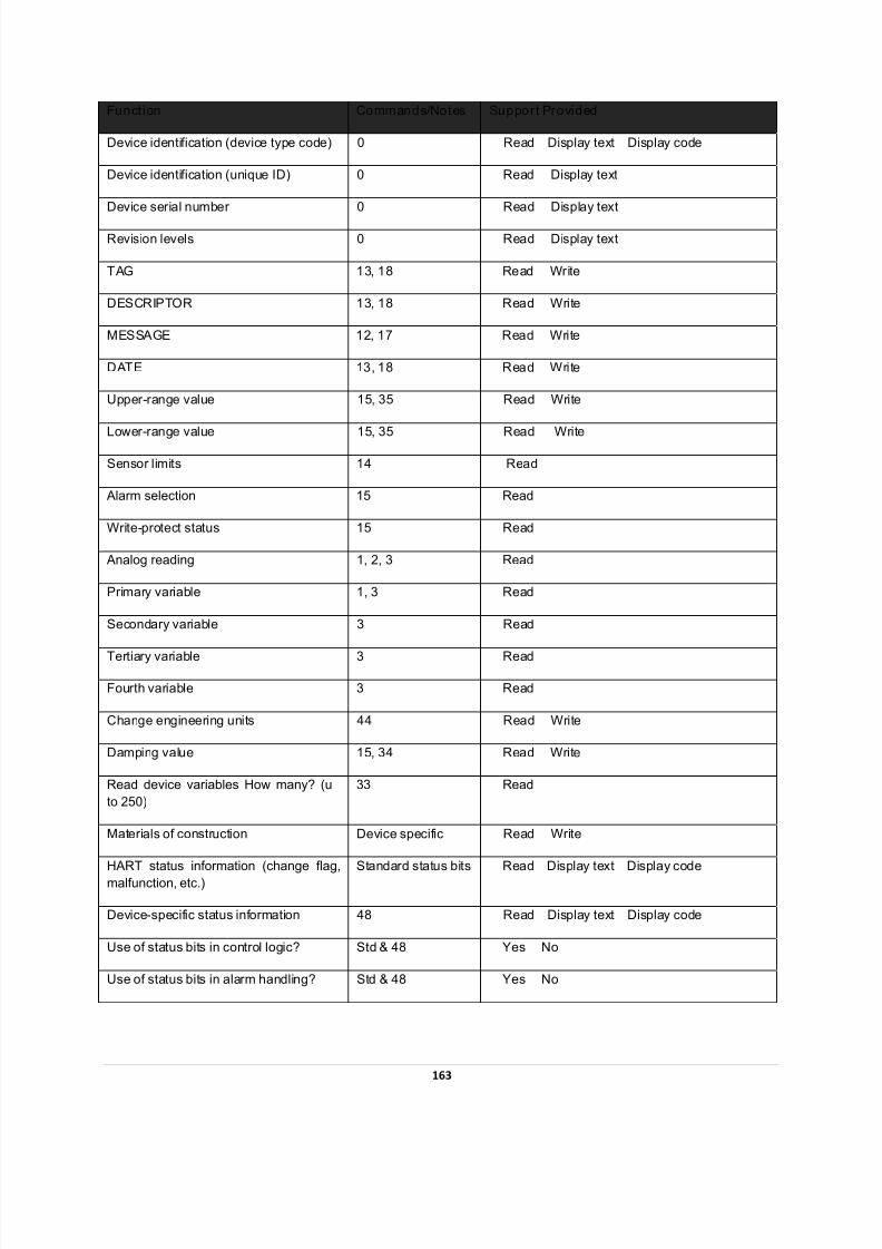
7/28/2019 HART Guide
http://slidepdf.com/reader/full/hart-guide 163/174
Funct ion Commands/Notes Support Provided
Device identification (device type code) 0 Read Display text Display code
Device identification (unique ID) 0 Read Display text
Device serial number 0 Read Display text
Revision levels 0 Read Display text
TAG 13, 18 Read Write
DESCRIPTOR 13, 18 Read Write
MESSAGE 12, 17 Read Write
DATE 13, 18 Read Write
Upper-range value 15, 35 Read Write
Lower-range value 15, 35 Read Write
Sensor limits 14 Read
Alarm selection 15 Read
Write-protect status 15 Read
Analog reading 1, 2, 3 Read
Primary variable 1, 3 Read
Secondary variable 3 Read
Tertiary variable 3 Read
Fourth variable 3 Read
Change engineering units 44 Read Write
Damping value 15, 34 Read Write
Read device variables How many? (u
to 250)
33 Read
Materials of construction Device specific Read Write
HART status information (change flag,
malfunction, etc.)
Standard status bits Read Display text Display code
Device-specific status information 48 Read Display text Display code
Use of status bits in control logic? Std & 48 Yes No
Use of status bits in alarm handling? Std & 48 Yes No
163
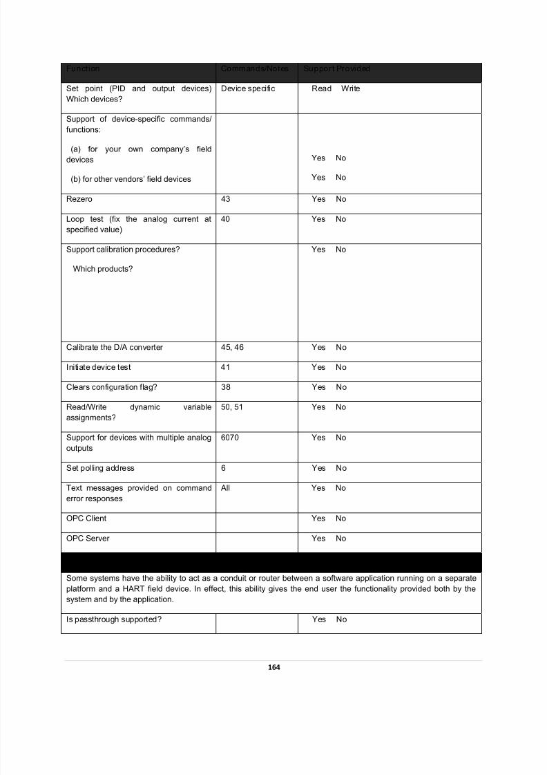
7/28/2019 HART Guide
http://slidepdf.com/reader/full/hart-guide 164/174
Funct ion Commands/Notes Support Provided
Set point (PID and output devices)
Which devices?
Device specific Read Write
Support of device-specific commands/
functions:
(a) for your own company’s field
devices
(b) for other vendors’ field devices
Yes No
Yes No
Rezero 43 Yes No
Loop test (fix the analog current at
specified value)
40 Yes No
Support calibration procedures?
Which products?
Yes No
Calibrate the D/A converter 45, 46 Yes No
Initiate device test 41 Yes No
Clears configuration flag? 38 Yes No
Read/Write dynamic variableassignments?
50, 51 Yes No
Support for devices with multiple analog
outputs
6070 Yes No
Set polling address 6 Yes No
Text messages provided on command
error responses
All Yes No
OPC Client Yes No
OPC Server Yes No
HART Command Passthrough
Some systems have the ability to act as a conduit or router between a software application running on a separate
platform and a HART field device. In effect, this ability gives the end user the functionality provided both by the
system and by the application.
Is passthrough supported? Yes No
164
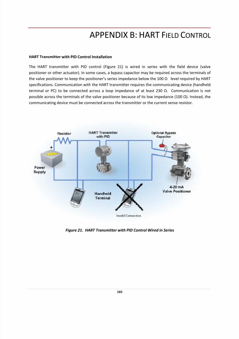
7/28/2019 HART Guide
http://slidepdf.com/reader/full/hart-guide 165/174
APPENDIX B: HART FIELD CONTROL
HART Transmitter with PID Control Installation
The HART transmitter with PID control (Figure 21) is wired in series with the field device (valve
positioner or other actuator). In some cases, a bypass capacitor may be required across the terminals of
the valve positioner to keep the positioner’s series impedance below the 100 Ω level required by HART
specifications. Communication with the HART transmitter requires the communicating device (handheld
terminal or PC) to be connected across a loop impedance of at least 230 Ω. Communication is not
possible across the terminals of the valve positioner because of its low impedance (100 Ω). Instead, the
communicating device must be connected across the transmitter or the current sense resistor.
Figure 21. HART Transmitter with PID Control Wired in Series
165
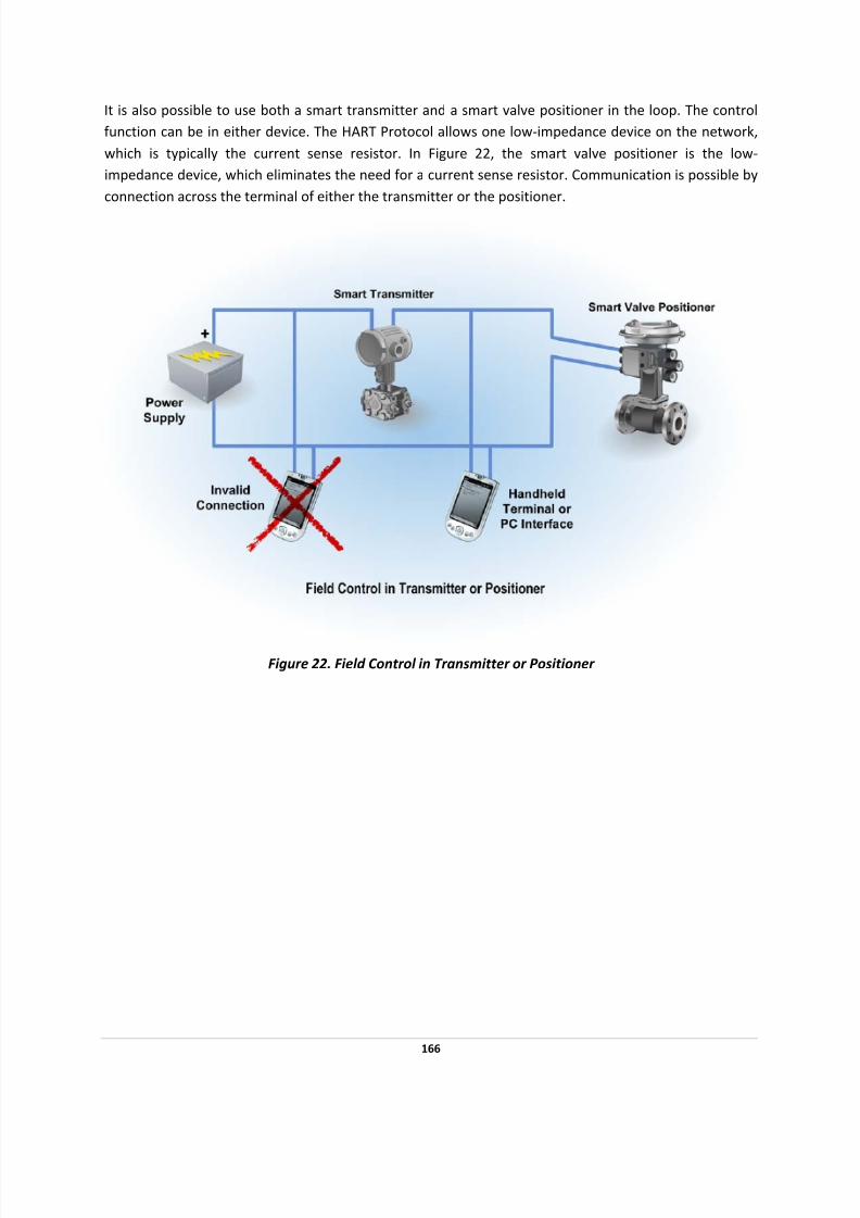
7/28/2019 HART Guide
http://slidepdf.com/reader/full/hart-guide 166/174
It is also possible to use both a smart transmitter and a smart valve positioner in the loop. The control
function can be in either device. The HART Protocol allows one low‐impedance device on the network,
which is typically the current sense resistor. In Figure 22, the smart valve positioner is the low‐
impedance device, which eliminates the need for a current sense resistor. Communication is possible by
connection across the terminal of either the transmitter or the positioner.
Figure 22. Field Control in Transmitter or Positioner
166
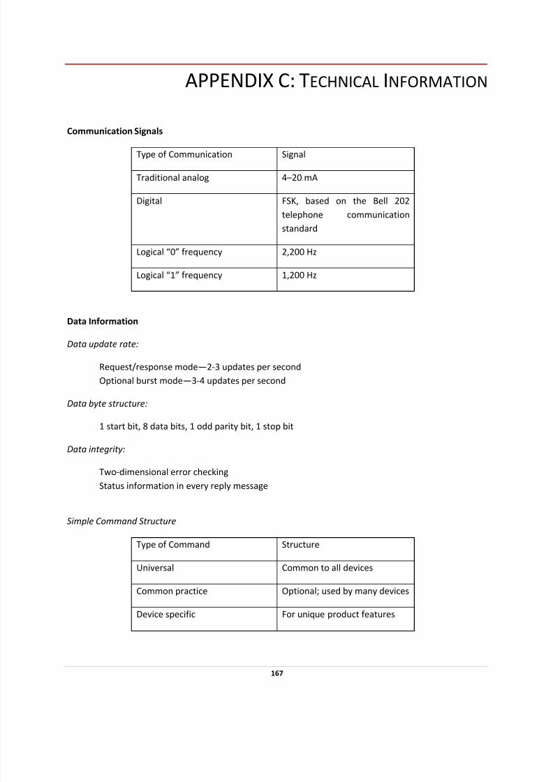
7/28/2019 HART Guide
http://slidepdf.com/reader/full/hart-guide 167/174
APPENDIX C: TECHNICAL INFORMATION
Communication Signals
Type of Communication Signal
Traditional analog 4–20 mA
Digital FSK, based on the Bell 202
telephone communication
standard
Logical “0” frequency 2,200 Hz
Logical “1” frequency 1,200 Hz
Data Information
Data update rate:
Request/response mode—2‐3 updates per second
Optional burst mode—3‐4 updates per second
Data byte structure:
1 start bit, 8 data bits, 1 odd parity bit, 1 stop bit
Data integrity:
Two‐dimensional error checking
Status information in every reply message
Simple Command Structure
Type of
Command
Structure
Universal Common to all devices
Common practice Optional; used by many devices
Device specific For unique product features
167
7/28/2019 HART Guide
http://slidepdf.com/reader/full/hart-guide 168/174
Communication Masters
Two communication masters
Variables
Up to 256 variables per device
IEEE 754 floating point format (32 bits) with engineering units
Wiring Topologies
Point‐to‐point—simultaneous analog and digital
Point‐to‐point—digital only
Multidrop network—digital only (up to 15 devices)
Cable Lengths
Maximum twisted‐pair length—10,000 ft (3,048 m) Maximum multiple twisted‐pair length—5,000 ft (1,524 m)
Cable length depends on the characteristics of individual products and cables.
168

7/28/2019 HART Guide
http://slidepdf.com/reader/full/hart-guide 169/174
GLOSSARY
Bell 202
A U.S. telephone standard that uses 1,200 Hz and 2,200 Hz as 1 and 0, respectively, at 1,200 baud; a full
duplex communication standard using a different pair of frequencies for its reverse channel. HART uses
Bell 202 signals but is a half ‐duplex system, so the reverse channel frequencies are not used.
Burst (Broadcast) Mode
A HART communication mode in which a master device instructs a slave device to continuously
broadcast a standard HART reply message (e.g., value of a process variable) until the master instructs it
to stop bursting
Cable Capacitance Per Unit of Length
The capacitance from one conductor to all other conductors (including the shield if present) in the network; measured in feet or meters
Cable Resistance Per Unit of Length
The resistance for a single wire; measured in feet or meters
Closed‐Loop Control
A system in which no operator intervention is necessary for process control
Communication Rate
The rate at which data are sent from a slave device to a master device; usually expressed in data
updates per second
DCS
See Distributed Control System.
Distributed Control System
Instrumentation (input/output devices, control devices, and operator interface devices) that permits
transmission of control, measurement, and operating information to and from user‐specified locations,
connected by a communication link
EDD/DD
See Device Description.
EDDL/DDL
See Device Description Language.
169

7/28/2019 HART Guide
http://slidepdf.com/reader/full/hart-guide 170/174
Electronic Device Description
A program file written in the HART Device Description Language (DDL) that contains an electronic
description of all of a device’s parameters and functions needed by a host application to communicate
with the device
Electronic Device
Description
Language
A standardized programming language used to write DDs for HART‐compatible field devices
Field
The area of a process plant outside the control room where measurements are made, and to and from
which communication is provided; a part of a message devoted to a particular function (e.g., the address
field or the command field)
Field Device
A device generally not found in the control room; field devices may generate or receive an analog signal
in addition to the HART digital communication signal
Frequency Shift Keying
Method of modulating digital information for transmission over paths with poor propagation
characteristics; can be transmitted successfully over telephone systems
FSK
See Frequency Shift Keying.
Gateway
A network device that enables other devices on the network to communicate with a second network
using a different protocol
HART Command Set
A series of commands that provide uniform and consistent communication for all master and slave
devices; includes Universal, Common Practice, and Device‐Specific commands
HART Communication Protocol
Highway Addressable
Remote
Transducer communication protocol; the industry standard protocol for
digitally enhanced 4‐20 mA communication with smart field devices
HART Handheld Communicator
A handheld master device that uses the HART Communication Protocol and DDL to configure or
communicate with any HART device
170

7/28/2019 HART Guide
http://slidepdf.com/reader/full/hart-guide 171/174
HART Loop
A communication network in which the master and slave devices are HART compatible
Host Application
A software
program
used
by
the
control
center
to
translate
information
received
from
field
devices
into
a format that can be used by the operator
Interoperability
The ability to operate multiple devices in the same system, independent of manufacturer, without loss
of functionality
Intrinsic Safety
A certification method for use of electrical equipment in hazardous (e.g., flammable) environments; a
type of protection in which a portion of an electrical system contains only intrinsically safe equipment
that is incapable of causing ignition in the surrounding environment
Intrinsic Safety Barrier
A network or device designed to limit the amount of energy available to the protected circuit in a
hazardous location
IS
See Intrinsic Safety.
Master Device
A device in a master‐slave system that initiates all transactions and commands (e.g., central controller)
Master‐Slave Protocol
Communication system in which all transactions are initiated by a master device and are received and
responded to by a slave device
Miscellaneous Series Impedance
The summation of the maximum impedance (500 Hz–10 kHz) of all devices connected in series between
two communicating devices; a typical nonintrinsically safe loop will have no miscellaneous series
impedance
Modem
Modulator/demodulator used to convert HART signals to RS232 signals
171
7/28/2019 HART Guide
http://slidepdf.com/reader/full/hart-guide 172/174
Multidrop Network
HART communication system that allows more than two devices to be connected together on a single
cable; usually refers to a network with more than one slave device
Multimaster
Multimaster refers to a communication system that has more than one master device. The HART
Protocol is a simple multimaster system allowing two masters; after receiving a message from a slave
device, the master waits for a short time before beginning another transmission, which gives the second
master time to initiate a message
Multiplexer
A device that connects to several HART loops and allows communication to and from a host application
Multivariable Instrument
A field device that can measure or calculate more than one process parameter (e.g., flow and
temperature)
Network
A series of field and control devices connected together through a communication medium
Parallel Device Capacitance
The summation of the capacitance values of all connected devices in a network
Parallel Device Resistance
The parallel combination of the resistance values of all connected devices in the network; typically,
there is only one low‐impedance device in the network, which dominates the parallel device‐resistance
value
Passthrough
A feature of some systems that allows HART Protocol send‐and‐receive messages to be communicated
through the system interface
PID
Proportional‐integral‐derivative
PID Control
Proportional‐plus‐integral‐plus‐derivative control; used in processes where the controlled variable is
affected by long lag times
172

7/28/2019 HART Guide
http://slidepdf.com/reader/full/hart-guide 173/174
Point‐to‐Point
A HART Protocol communication mode that uses the conventional 4‐20 mA signal for analog
transmission, while measurement, adjustment, and equipment data are transferred digitally; only two
communicating devices are connected together
Polling
A method of sequentially observing each field device on a network to determine if the device is ready to
send data
Polling Address
Every HART device has a polling address; address 0 is used for point‐to‐point networks; addresses 1‐15
are used in multidrop networks
Process Variable
A process parameter that is being measured or controlled (e.g., level, flow, temperature, mass, density,
etc.)
Protocol
A set of rules to be used in generating or receiving a message
PV
See Process Variable.
Remote Terminal Unit
A self ‐contained control unit that is part of a SCADA system
RTU
See Remote Terminal Unit.
SCADA
See Supervisory Control and Data Acquisition.
Slave Device
A device (e.g., transmitter or valve) in a master‐slave system that receives commands from a master
device; a slave device cannot initiate a transaction
Smart Instrumentation
Microprocessor‐based instrumentation that can be programmed, has memory, is capable of performing
calculations and self ‐diagnostics and reporting faults, and can be communicated with from a remote
location
173

7/28/2019 HART Guide
http://slidepdf.com/reader/full/hart-guide 174/174
Supervisory Control and Data Acquisition
A control system using communications such as phone lines, microwaves, radios, or satellites to link
RTUs with a central control system
Zener
Type of shunt‐diode barrier that uses a high‐quality safety ground connection to bypass excess energy