Embed Size (px)
Citation preview
1954 Technology Drive, P.O. Box 4225 Peterborough, Ontario K9J 7B1 / Canada
Tel.: (705) 745-2431 Fax: (705) 741-0466 www.siemens.com/sensorsystems
Siemens Canada Limited Siemens Milltronics Process Instruments
AG012712
Working with HART networks
Objective: Learn how to implement a trouble-free HART network Learn how to integrate HART devices into the control system
Equipment: Siemens HART instrument SIMATIC PDM or PACTware
HART modem PC or laptop
While every effort was made to verify the following information, no warranty of accuracy or usability is expressed or implied.
Overview HART is a communication protocol for field instruments. It has become very popular and is generally very easy to use. However, there are design rules, restrictions, and wiring tips that HART users should be aware of that are presented in this guide. What is HART? Highway Addressable Remote Transducer (HART) is an industrial protocol designed to replace 4-20 mA technology for analog input and output field devices. It is designed to:
Use the same wires as 4-20 mA devices Permit remote configuration of devices Permit remote diagnostics Allow for transmission of multiple variables Permit Intrinsic Safety Permit multi-drop of instruments
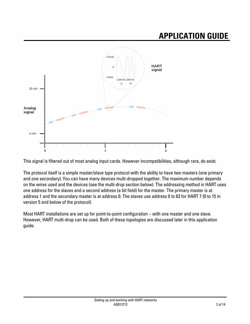
HART does this by combining both analog and digital communication. The main process variable is transmitted via the analog channel. All other information is communicated via a digital channel which is super-imposed on the analog signal using Bell 202 frequency shift keying (FSK). The digital signal uses two different frequency bursts to represent a binary ‘1’ and ‘0’. A ‘1’ is encoded using a 1200 Hz frequency burst and a ‘0’ is encoded using a 2200 Hz frequency burst. The mean value of the burst is zero, so the slow moving 4-20 mA signal is generally not affected.
APPLICATION GUIDE
Setting up and working with HART networks AG012712 2 of 14
APPLICATION GUIDE
+0.5mA
-0.5mA
20 mA
4 mA
0 1 2
1200 Hz
"1"
2200 Hz
"0"
0
Analogsignal
HARTsignal
This signal is filtered out of most analog input cards. However incompatibilities, although rare, do exist. The protocol itself is a simple master/slave type protocol with the ability to have two masters (one primary and one secondary). You can have many devices multi-dropped together. The maximum number depends on the wires used and the devices (see the multi-drop section below). The addressing method in HART uses one address for the slaves and a second address (a bit field) for the master. The primary master is at address 1 and the secondary master is at address 0. The slaves use address 0 to 63 for HART 7 (0 to 15 in version 5 and below of the protocol). Most HART installations are set up for point-to-point configuration – with one master and one slave. However, HART multi-drop can be used. Both of these topologies are discussed later in this application guide.
Setting up and working with HART networks AG012712 3 of 14
APPLICATION GUIDE
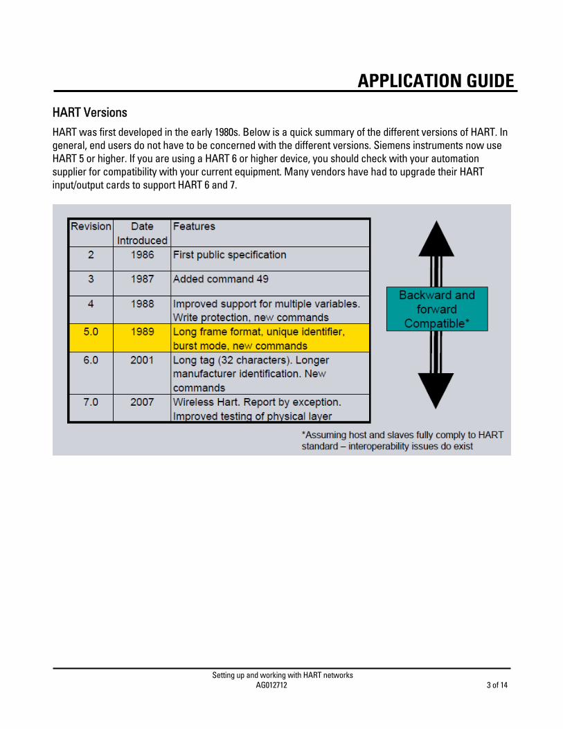
HART Versions HART was first developed in the early 1980s. Below is a quick summary of the different versions of HART. In general, end users do not have to be concerned with the different versions. Siemens instruments now use HART 5 or higher. If you are using a HART 6 or higher device, you should check with your automation supplier for compatibility with your current equipment. Many vendors have had to upgrade their HART input/output cards to support HART 6 and 7.
Setting up and working with HART networks AG012712 4 of 14
APPLICATION GUIDE
Basic Design Rules Although HART networks are very easy to put together, there are still design rules that must be followed:
Minimum loop resistance: For HART communications to occur, you need a minimum loop resistance of 250 ohms. Most HART input/output cards will have this resistance built in. However, if you are using a HART modem, you need to know how long the wire is and the resistance of the wire so that you know if you need to add any resistance. For short runs under 100 meters, it is fairly safe to assume that you need to add a 250 ohm resistor.
Maximum RC value: For HART communications to occur you must have an RC value of the wire less
than 65 μs. The RC value is the total resistance of the circuit multiplied by the total capacitance. The first rule sets the minimum resistance, and this rule sets the maximum. In both cases the more complex the network, the harder this calculation is, and the more important it is. Again, if it is a point-to-point topology and the run is less than 100 meters, then this is not a concern.
Minimum operating voltage: For all HART devices, there is a minimum voltage that is required for the
device to work. This value is different for all devices. If the device does not get the required voltage then it will not operate. If there is too much loop resistance, at a low current the device may power-up however, once the PV begins calculating at high currents, the voltage drop on the loop will increase and the device will turn off. This rule, like the RC rule above, also sets a maximum value on the loop resistance.
Cable: The choice of the cable matters. As the first two rules imply, the type of cable used will
impact the loop resistance and the RC value. For very short runs, HART will run on almost anything. However, as distance increases, the importance of your choice of wire increases as well. Also, the better the cable, the better the noise immunity. In general, you want to pick a shielded twisted pair instrument grade wire and perform the calculations before you buy and install the wires. It is also a good idea to buy a cable designed for HART. Belden 3105A is an example of such a cable.
Power supply: There is a specification on the power supply. All the Siemens industrial power
supplies reviewed by the factory meet the HART specification and most of the industrial power supplies do as well however, it is still a good idea to verify this prior to installation. The power supply specifications are:
Maximum ripple (47 to 125 Hz) = 0.2V p-p Maximum noise (500 Hz to 10 kHz) = 1.2 mV rms Maximum series impedance (500 Hz to 10 kHz) = 10 ohm
Setting up and working with HART networks AG012712 5 of 14
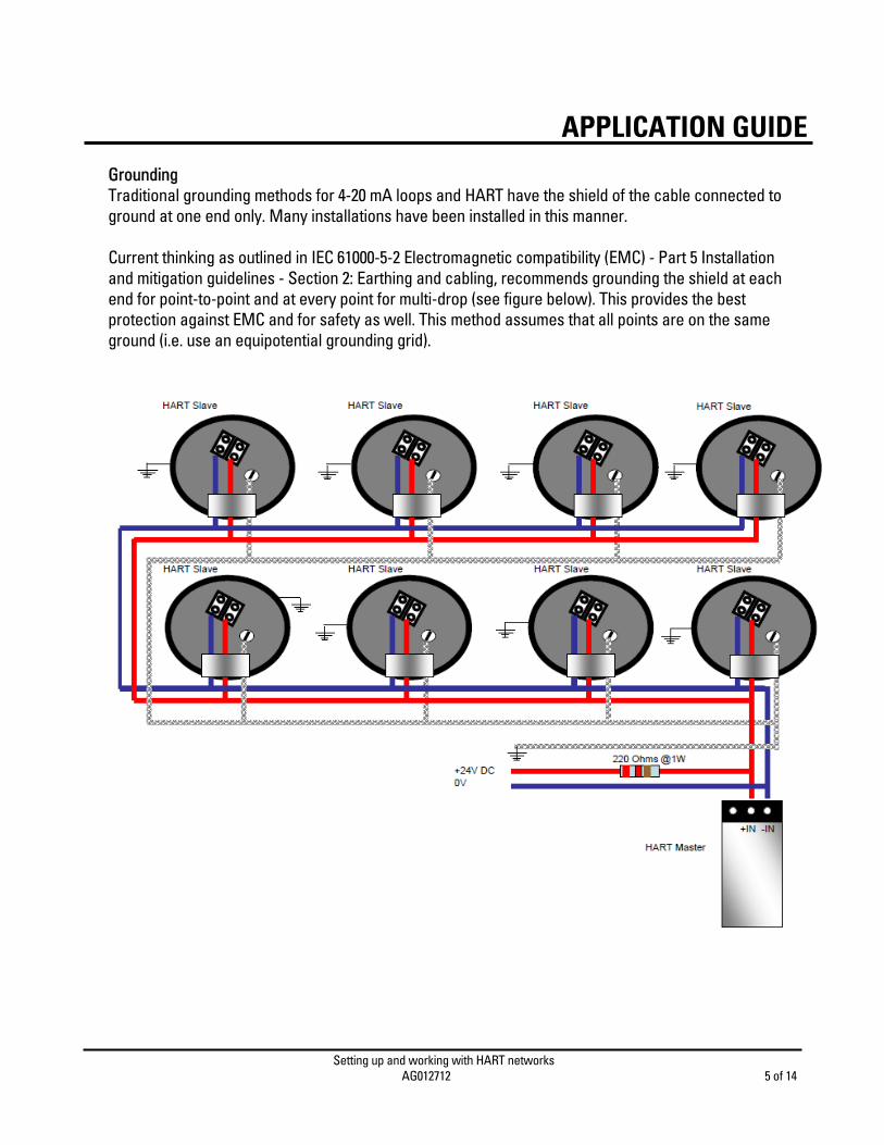
APPLICATION GUIDEGrounding Traditional grounding methods for 4-20 mA loops and HART have the shield of the cable connected to ground at one end only. Many installations have been installed in this manner. Current thinking as outlined in IEC 61000-5-2 Electromagnetic compatibility (EMC) - Part 5 Installation and mitigation guidelines - Section 2: Earthing and cabling, recommends grounding the shield at each end for point-to-point and at every point for multi-drop (see figure below). This provides the best protection against EMC and for safety as well. This method assumes that all points are on the same ground (i.e. use an equipotential grounding grid).

Setting up and working with HART networks AG012712 6 of 14
APPLICATION GUIDECable separation Where you lay your HART cable also has a big impact on the amount of noise induced into that cable. Communication and power cables need to be separated. The diagram below shows the recommended cable separation from the Ontario Electrical Safety code. Always check your local electrical regulations. If the cable is too close to a power cable, noise will be induced onto the communication cable and this can easily cause bit errors in the HART message.
COMMUNICATIONSCABLE(HART)
<= 300V POWER CABLES
> 300V POWER CABLES
> 50 mm a)
> 600 mm a)
a) Recommendations from the Ontario Electrical Safety Code
Check your local electrical regulations.
Update rates The analog channel is updated continuously. However there are still two built-in delays. The first is in the instrument where there will be a small delay caused by the digital-to-analog conversion. This value is typically not published separately and is built into the update rate of the instrument. The second delay is the delay at the analog input card where the analog signal is converted into a digital value. This is a published value and varies greatly between different types of input cards and manufacturers. This update rate should be considered when choosing the input cards. The digital channel can handle between 2 to 3 messages per second. When multi-dropping instruments, the number of instruments will have a large impact on the update rate of the PV into the control system. This rate should also be considered if you are using a multipoint HART input card where the HART channel is multiplexed between the different points.
Setting up and working with HART networks AG012712 7 of 14
APPLICATION GUIDE
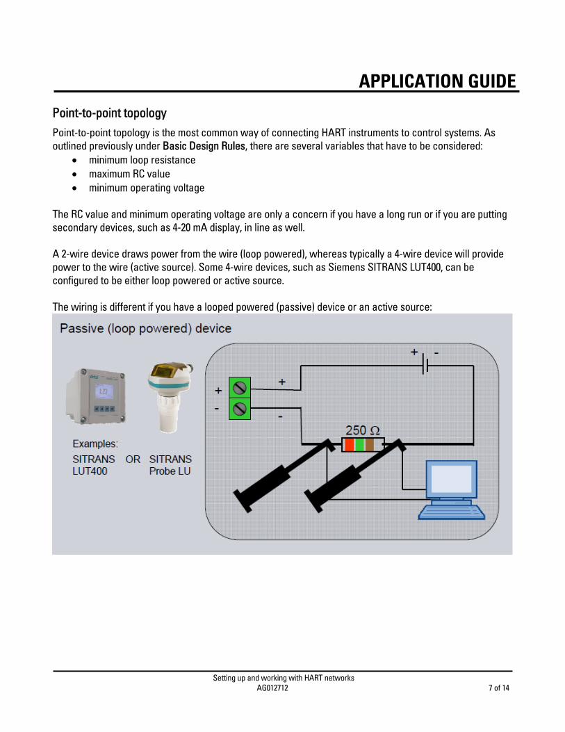
Point-to-point topology Point-to-point topology is the most common way of connecting HART instruments to control systems. As outlined previously under Basic Design Rules, there are several variables that have to be considered:
minimum loop resistance maximum RC value minimum operating voltage
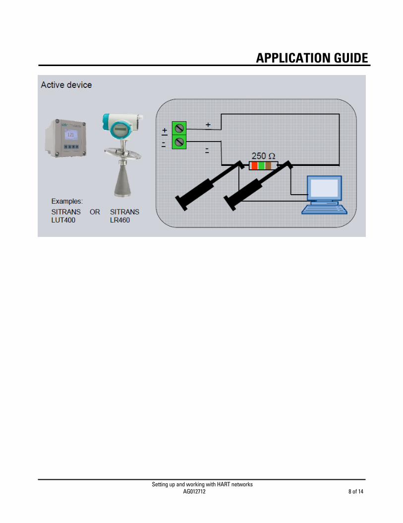
The RC value and minimum operating voltage are only a concern if you have a long run or if you are putting secondary devices, such as 4-20 mA display, in line as well. A 2-wire device draws power from the wire (loop powered), whereas typically a 4-wire device will provide power to the wire (active source). Some 4-wire devices, such as Siemens SITRANS LUT400, can be configured to be either loop powered or active source. The wiring is different if you have a looped powered (passive) device or an active source:
Setting up and working with HART networks AG012712 8 of 14
APPLICATION GUIDE

Setting up and working with HART networks AG012712 9 of 14
APPLICATION GUIDE
Multi-drop Topology Multi-drop topologies are not as common place as point-to-point, but it has been gaining some popularity in certain applications. The two issues that multi-dropping HART has are:
o update rate is very slow o you have to design the network
As is mentioned in the Update rates section, the communication rate for HART messages is about two per second. When HART devices are multi-dropped, the analog channel can no longer be used for the Process Variable, so the digital channel has to be used. If you multi-drop two devices, your update rate will be once per second. As the number increases, your update rate increases. This is not acceptable in many applications but is in some non-time critical applications. This is where HART multi-drop can be used. The HART addressing method permits devices to have an address of between 0 and 63 in HART 6 device and above. Earlier revisions of HART (version 5 and before) only permitted addresses from 0 to 15. However, for all practical purposes, it is hard to multi-drop much more than 8 devices due to design issues and current loads. Therefore it is best to use addressing in the 0 to 15 range. When designing a HART multi-drop network, you have to know:
o electrical characteristics of the wire being used o start-up current of all devices o steady state current of all devices o minimum start-up voltage of all devices o power source of devices used (loop powered or active source)
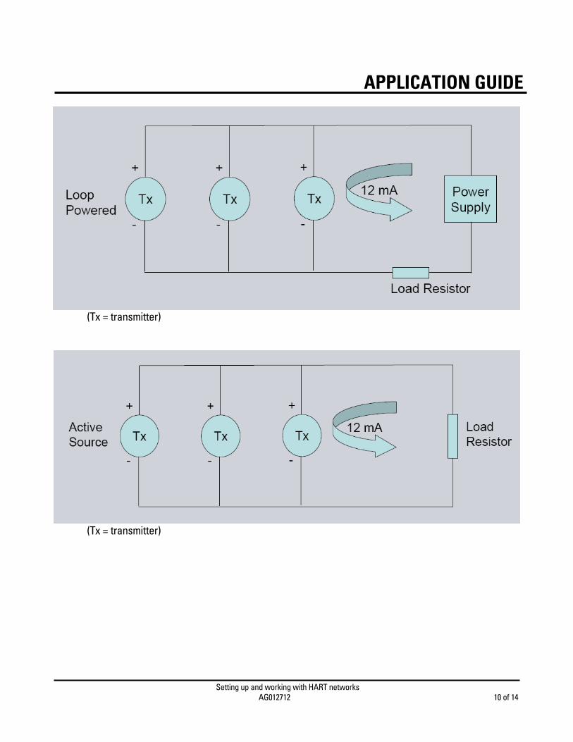
NOTE: When using SIMATIC PDM on a HART multi-drop network, only one instrument can be viewed at any one time. The wiring will differ greatly, dependent on whether all devices are loop powered, active source or a combination of the two. See connection diagrams for each below.
Setting up and working with HART networks AG012712 10 of 14
APPLICATION GUIDE
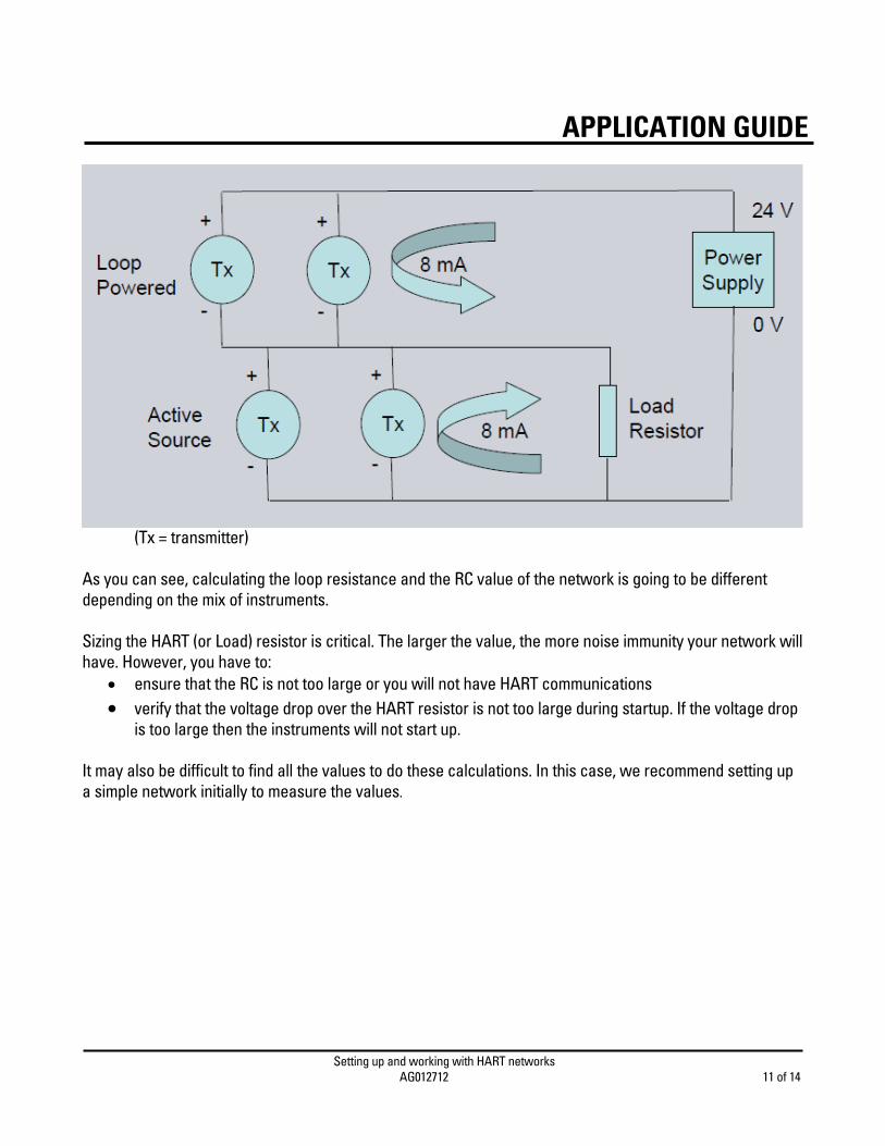
(Tx = transmitter)
(Tx = transmitter)
Setting up and working with HART networks AG012712 11 of 14
APPLICATION GUIDE
(Tx = transmitter) As you can see, calculating the loop resistance and the RC value of the network is going to be different depending on the mix of instruments. Sizing the HART (or Load) resistor is critical. The larger the value, the more noise immunity your network will have. However, you have to:
ensure that the RC is not too large or you will not have HART communications verify that the voltage drop over the HART resistor is not too large during startup. If the voltage drop
is too large then the instruments will not start up. It may also be difficult to find all the values to do these calculations. In this case, we recommend setting up a simple network initially to measure the values.
Setting up and working with HART networks AG012712 12 of 14
APPLICATION GUIDE
Integrating HART devices into the Control System HART devices can have different levels of integration into the control system. Most HART devices are wired into 4-20 mA cards so that the control system has no information about the instruments and the only way to access device information is to go to the device and connect up point-to-point with a HART modem. The next level of integration is using a HART card or a HART multiplexer where you can then get access to the information easily. At this level, you again have several options. The simplest option is to just use the HART channel for configuration and diagnostic software such as SIMATIC PDM to talk to the instruments. To get all the benefits of HART, it is best to invest in programming time to obtain the status information. HART has the following status information:
1. ‘Command Status Bytes’ which comes back in every HART response message 2. ‘Additional Device Status’ which comes back from HART command 48 3. ‘Extended Device Status Codes’ and ‘Device Variable Status’ which comes back from HART
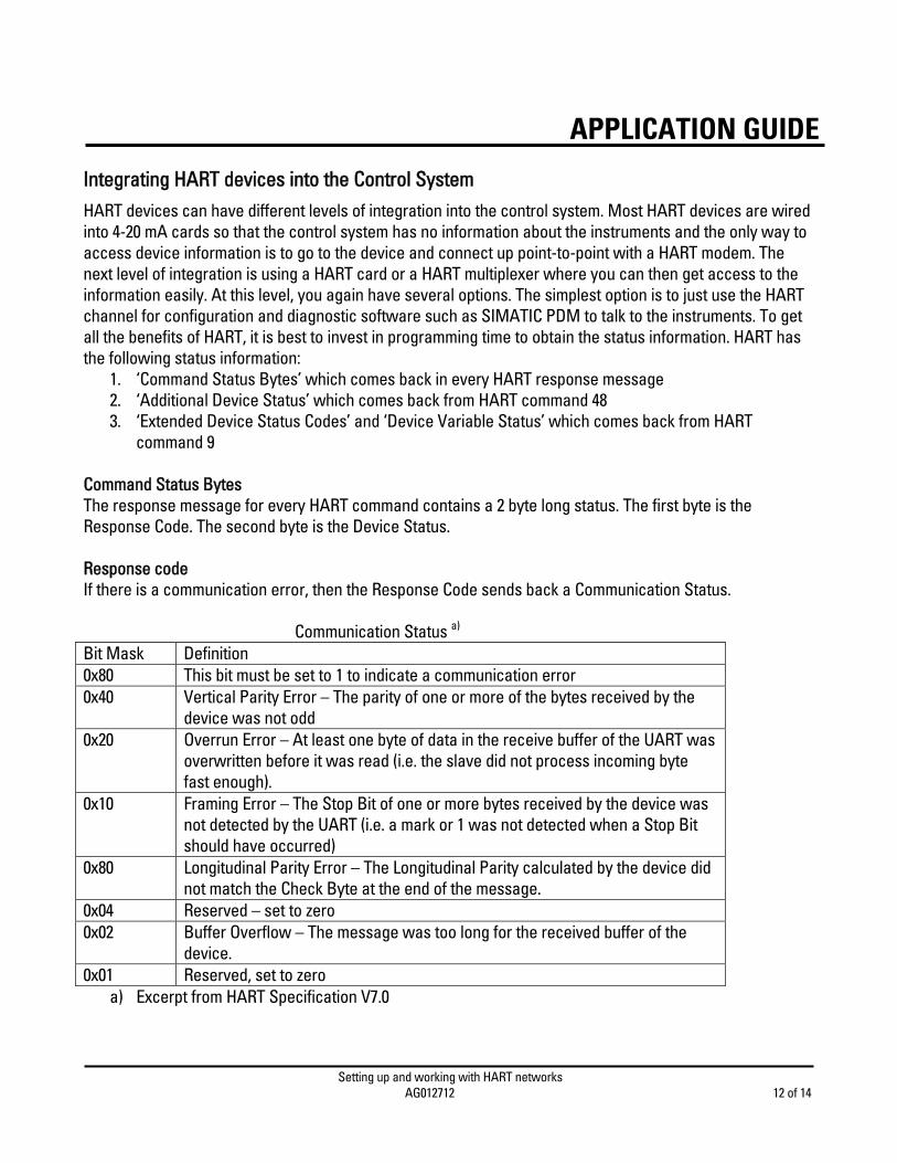
command 9 Command Status Bytes The response message for every HART command contains a 2 byte long status. The first byte is the Response Code. The second byte is the Device Status. Response code If there is a communication error, then the Response Code sends back a Communication Status. Communication Status a) Bit Mask Definition 0x80 This bit must be set to 1 to indicate a communication error 0x40 Vertical Parity Error – The parity of one or more of the bytes received by the
device was not odd 0x20 Overrun Error – At least one byte of data in the receive buffer of the UART was
overwritten before it was read (i.e. the slave did not process incoming byte fast enough).
0x10 Framing Error – The Stop Bit of one or more bytes received by the device was not detected by the UART (i.e. a mark or 1 was not detected when a Stop Bit should have occurred)
0x80 Longitudinal Parity Error – The Longitudinal Parity calculated by the device did not match the Check Byte at the end of the message.
0x04 Reserved – set to zero 0x02 Buffer Overflow – The message was too long for the received buffer of the
device. 0x01 Reserved, set to zero
a) Excerpt from HART Specification V7.0

Setting up and working with HART networks AG012712 13 of 14
APPLICATION GUIDEIf no communication error occurred, then the response code will have a zero in the most significant bit and the code is a value of 0 to 127. A value of zero indicates that everything is OK with the command. A non-zero value indicates a warning or error and is different for each HART command. Device Status This byte indicates the current operating status of the field device as a whole. The table below gives the bit masks for this value and their meanings. Please note that prior to HART version 6, if there was a communication error, then this value would not be meaningful in the response code. In HART version 6 and above, it is now required that this value is meaningful in every response. Device Status a) Bit Mask Definition 0x80 Device Malfunction – The device detected a serious error or failure that
compromises device operation 0x40 Configuration Changed – An operation was performed that changed the
device’s configuration 0x20 Cold Start – A power failure or Device Reset has occurred 0x10 More Status Available – More status information is available via Command 48,
Read Additional Status Information. 0x08 Loop Current Fixed – The Loop Current is being held at a fixed value and is not
responding to process variations. 0x04 Loop Current Saturated – The Loop Current has reached its upper (or lower)
endpoint limit and cannot increase (or decease) any further. 0x02 Non-Primary Variable Out of Limits – A Device Variable not mapped to the PV
is beyond its operating limits. 0x01 Primary Variable Out of Limits – The PV is beyond its operating limit.
a) Excerpt from HART Specification V7.0 It should also be noted that the chart above is for HART 7. This chart has been evolving over time. Bits have been added, but none removed. Some meanings have also evolved. For example in HART 7, a process problem like loss of echo would have the device issuing a value of 0x90 (0x80 + 0x10) meaning that you can not trust your PV and that there are more status available. A HART 6 device would issue a 0x80 only if a device malfunctioned, and a loss of echo would cause only a 0x10 value. Additional Device Status HART command 48 is used to read Additional Device Status. The response message contains 25 bytes of data. Bytes 0 to 5 and 14 to 24 hold the Device-Specific Status which corresponds to the Error Display Codes shown on the screen of the device. The mapping is related to bit location of the bit value ‘1’ in the Device-Specific Status.

Setting up and working with HART networks AG012712 14 of 14
APPLICATION GUIDEFor example if there is a ‘1’ located in bit 4 of byte 0 of the response message, then that will correspond to and error code 4. If byte 2 of the response message has a 1 in bit 0, then it would be code 2*8+0=16. This HART command has also evolved over time. It was a Common Practice Command and now in HART 7, it is a Universal Command. It has also expanded in size as well, adding more bits to extend the possible error messages. Device Variable Status and Extended Field Device Status HART command 9 which was added in HART V6, is a command that can be used to read any variable in a device. Byte 0 of the response data defines the Extended Field Device Status. Byte 8 of the response data is the Device Variable Status for slot 0 request and Byte 16 for slot 1 and Byte 24 for slot 2 and so on up to slot 7. For HART 6 devices the device can return 4 slots of data, in HART 7, it can return 8 (0 to 7). The Extended Field Device Status byte has two used bit fields: Bit 1 – Maintenance Required. This bit is set to indicate that while the device has not malfunctioned, the Field Device requires maintenance. Bit 2 – Device Variable Alert – This bit is set if any Device Variable is in an Alarm or Warning State. The host should identify the Device Variable(s) causing this to be set using the Device Variable Status indicators. Device Variable Status – This is a measure of the overall health of the variable being read. The chart below gives the meanings of this status:
Summary HART is a protocol that has been around for a long time and has many ways in which to connect to instruments. As with most technology, it is best when approached with knowledge and forethought.