Embed Size (px)
DESCRIPTION
Manual de entrenamento de MPLAB Harmony
Citation preview
TLS4102
Getting Started with
MPLAB® Harmony Framework
Alain SORIN
Principal Technical Training Eng.
Microchip Technology Inc.
Lab Manual
V0.98f-dev-help 24 Mar. 2015
Harmony v1.03.01
TLS4102 class : Getting started with MPLAB® Harmony Framework
Page 2
Table of Contents
LABs Installation Procedure…..………….…..……………...…..…5
LAB 1a: Blinky LED……………………………………………….…6
LAB 1b: Adding UART Communication…………………………. 23
LAB 2a: Adding Graphics Library………………………………… 31
LAB 2b: Multi-Stacks – Creating Complex Harmony Projects.....44
LAB 3: Migration in MPLAB® Harmony……………..….………….66
Lab 4 Demo: MPLAB
® Harmony and RTOSes...........................78
Development Boards……………………….……………………….80

TLS4102 class : Getting started with MPLAB® Harmony Framework
Page 3
Hands-on class Introduction:
In the labs you will be requested to follow specific and certain steps to configure the
PIC32 MCU. Due to the limited time allotted for each lab the background details as to
why each configuration is requested is not provided. Upon completion of the class labs
you are encouraged to further your knowledge and understanding on the PIC32 MCU
setup and configuration options.
Note: This workshop is designed to support both PIC32MZ Starter Kits:
1. PIC32MZ Embedded Connectivity Starter Kit
part # DM320006 (PIC32MZ2048ECH144 MCU)
2. PIC32MZ Embedded Connectivity Starter Kit w/Crypto Engine
part # DM320006-C, (PIC32MZ2048ECM144 MCU)
Hands-on Class know-how Prerequesites:
The workshop lab material assumes the attendee has prior experience with:
1. MPLAB® X IDE fundamentals
2. MPLAB based Programming/Debugging fundamentals
3. ‘C’ language programming
4. Basic knowledge on PIC32 product family
Upon completion of this workshop you will:
1. Gain a basic understanding how to create an MPLAB® X and Harmony project
2. Gain a basic understanding and foundation on MPLAB® Harmony Framework
3. Gain hands-on experience with MPLAB® Harmony Framework components
4. Gain hands-on experience with the MPLAB® Harmony Configurator Tool
5. Gain overall understanding on key benefits and features of MPLAB® Harmony

TLS4102 class : Getting started with MPLAB® Harmony Framework
Page 4
Hardware / software installation:
Note: If you are not using a Microchip Training Center laptop, please install the
following software:
PC installation
1. MPLAB® X IDE: v2.30 (or later)
2. MPLAB® XC32 compiler : v1.34 (or later)
3. MPLAB® Harmony v1.03.01
4. MPLAB® Harmony Configurator (MHC) plugin for MPLAB® X IDE
C:\microchip\harmony\v1_03_01\utilities\mhc\com-microchip-mplab-modules-mhc.nbm
5. Windows® XP or Windows® 7 PC with two USB ports
(MHC will support Apple MAC in Q2 2015)
6. Tera Term or other terminal emulator program
Hardware equipment
1. PIC32MZ Embedded Connectivity Starter Kit
part # DM320006 (without crypto engine….. PIC32MZ2048ECH144 MCU)
or # DM320006-C (with crypto engine……….PIC32MZ2048ECM144 MCU)
2. Multimedia Expansion Board II (DM320005-2)
3. UART to USB bridge expansion board (AC320101)
4. USB pen drive (USB key) formatted with FAT16 or FAT32
5. 9V power supply
6. mini USB-to-USB cable
For Presenter only (demo labs):
1. PIC32MX USB starter kit II (ref DM320003-2) (DM320004 can also be used)
2. Multimedia Expansion Board (ref DM320005)

TLS4102 class : Getting started with MPLAB® Harmony Framework
Page 5
Move downloaded lab files into Harmony folder:
Important!
The lab files downloaded from the Microchip Developer Help site need to be placed in
a specific directory level, relative to the Harmony installation directory
(c:/microchip/harmony/v1_xx). If this is not done, the lab projects will not build
successfully because the projects won’t be able to find files that have been included
using relative paths.
Un-zip the files to this directory:
<harmony install path>/apps
With Harmony v1.03, the “apps”
directory will look like this when you
are done:

TLS4102 class : Getting started with MPLAB® Harmony Framework
Page 6
LAB 1a: Blinky LED
TLS4102 class : Getting started with MPLAB® Harmony Framework
Page 7
LAB 1a: Blinky LED
Purpose: After completing LABab 1a, you will have an understanding of the fundamental
elements, layout, and execution model of a MPLAB® Harmony project. You will also
gain hands-on knowledge in using the MPLAB® Harmony Configurator tool (MHC) to
configure the MPLAB® Harmony project and to add features and functionality.
Overview:
In this lab you will create a simple MPLAB® Harmony project starting from scratch,
beginning with opening MPLAB® X IDE. The lab result will implement a Timer Driver to
blink an LED on the PIC32MZ EC Starter Kit. The lab will demonstrate basic system
initialization, polled-state machine design, and use of system services.
Procedure:
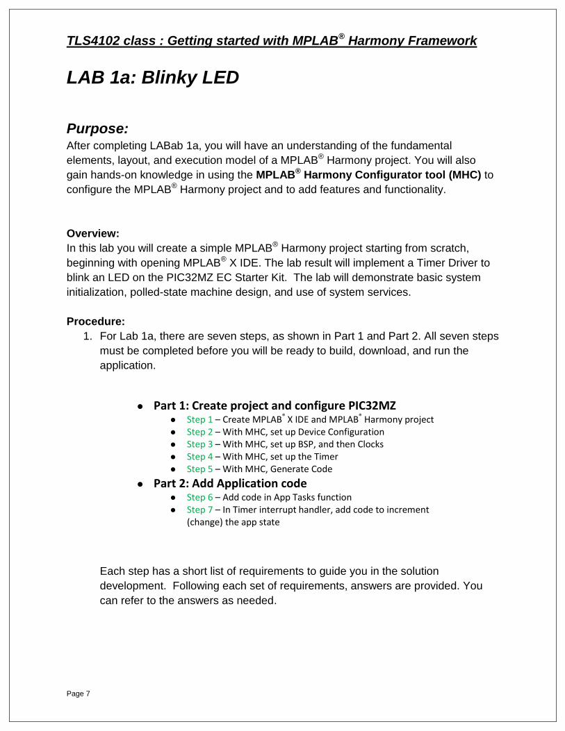
1. For Lab 1a, there are seven steps, as shown in Part 1 and Part 2. All seven steps
must be completed before you will be ready to build, download, and run the
application.
Each step has a short list of requirements to guide you in the solution
development. Following each set of requirements, answers are provided. You
can refer to the answers as needed.
Part 1: Create project and configure PIC32MZ
Step 1 – Create MPLAB® X IDE and MPLAB® Harmony project
Step 2 – With MHC, set up Device Configuration
Step 3 – With MHC, set up BSP, and then Clocks
Step 4 – With MHC, set up the Timer Step 5 – With MHC, Generate Code
Part 2: Add Application code
Step 6 – Add code in App Tasks function
Step 7 – In Timer interrupt handler, add code to increment (change) the app state
TLS4102 class : Getting started with MPLAB® Harmony Framework
Page 8
Step 1: Objective – Create MPLAB® Harmony Project
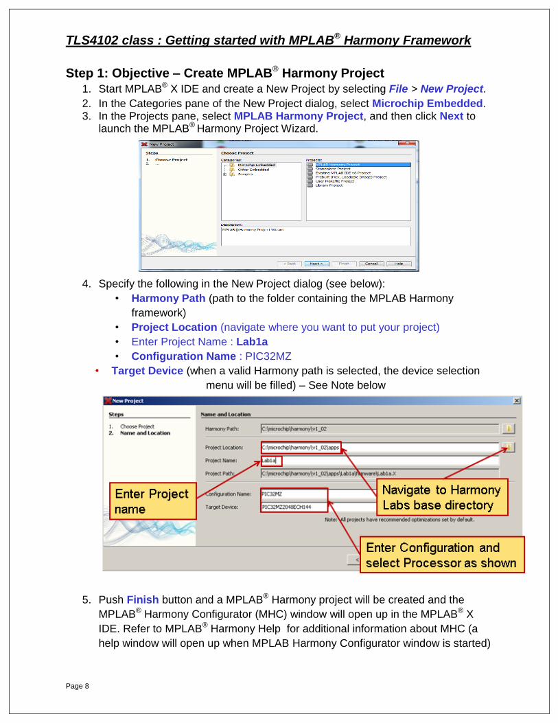
1. Start MPLAB® X IDE and create a New Project by selecting File > New Project.
2. In the Categories pane of the New Project dialog, select Microchip Embedded. 3. In the Projects pane, select MPLAB Harmony Project, and then click Next to
launch the MPLAB® Harmony Project Wizard.
4. Specify the following in the New Project dialog (see below):
• Harmony Path (path to the folder containing the MPLAB Harmony
framework)
• Project Location (navigate where you want to put your project)
• Enter Project Name : Lab1a
• Configuration Name : PIC32MZ
• Target Device (when a valid Harmony path is selected, the device selection
menu will be filled) – See Note below
5. Push Finish button and a MPLAB® Harmony project will be created and the
MPLAB® Harmony Configurator (MHC) window will open up in the MPLAB® X
IDE. Refer to MPLAB® Harmony Help for additional information about MHC (a
help window will open up when MPLAB Harmony Configurator window is started)
TLS4102 class : Getting started with MPLAB® Harmony Framework
Page 9
Note: The labs will support either the PIC32MZ Embedded Connectivity Starter Kit,
DM320006 (PIC32MZ2048ECH144 MCU) or PIC32MZ Embedded Connectivity Starter
Kit w/Crypto Engine, DM320006-C, (PIC32MZ2048ECM144 MCU).
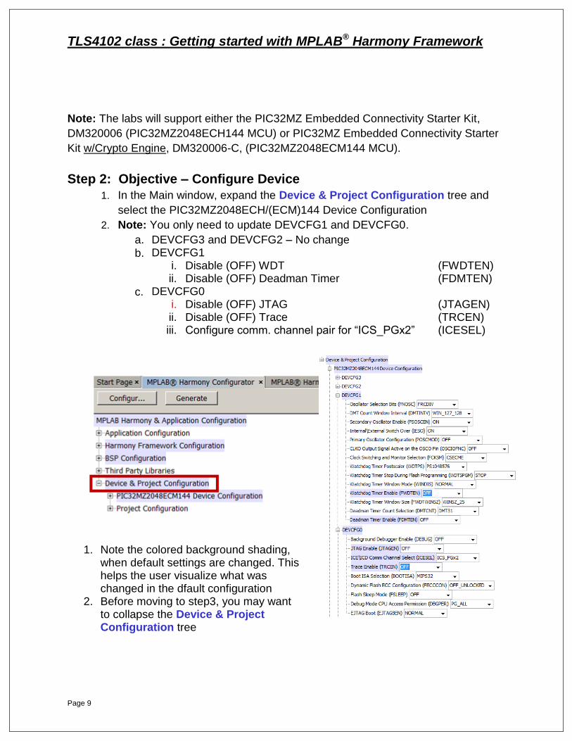
Step 2: Objective – Configure Device
1. In the Main window, expand the Device & Project Configuration tree and
select the PIC32MZ2048ECH/(ECM)144 Device Configuration
2. Note: You only need to update DEVCFG1 and DEVCFG0.
a. DEVCFG3 and DEVCFG2 – No change
b. DEVCFG1 i. Disable (OFF) WDT (FWDTEN) ii. Disable (OFF) Deadman Timer (FDMTEN)
c. DEVCFG0 i. Disable (OFF) JTAG (JTAGEN) ii. Disable (OFF) Trace (TRCEN) iii. Configure comm. channel pair for “ICS_PGx2” (ICESEL)
1. Note the colored background shading,
when default settings are changed. This helps the user visualize what was changed in the dfault configuration
2. Before moving to step3, you may want to collapse the Device & Project Configuration tree

TLS4102 class : Getting started with MPLAB® Harmony Framework
Page 10
Step 2: Solution
1. Select PIC32MZ2048ECH/(ECM)144 Device Configuration
a. DEVCFG3 – No change b. DEVCFG2 – No change c. DEVCFG1
i. (OFF) Watchdog Timer ii. (OFF) Deadman Timer
d. DEVCFG0
i. (OFF) JTAG Enable ii. ICE\ICD : ICS_PGx2 iii. (OFF) Trace Enable
Note background shading, when default settings are changed
TLS4102 class : Getting started with MPLAB® Harmony Framework
Page 11
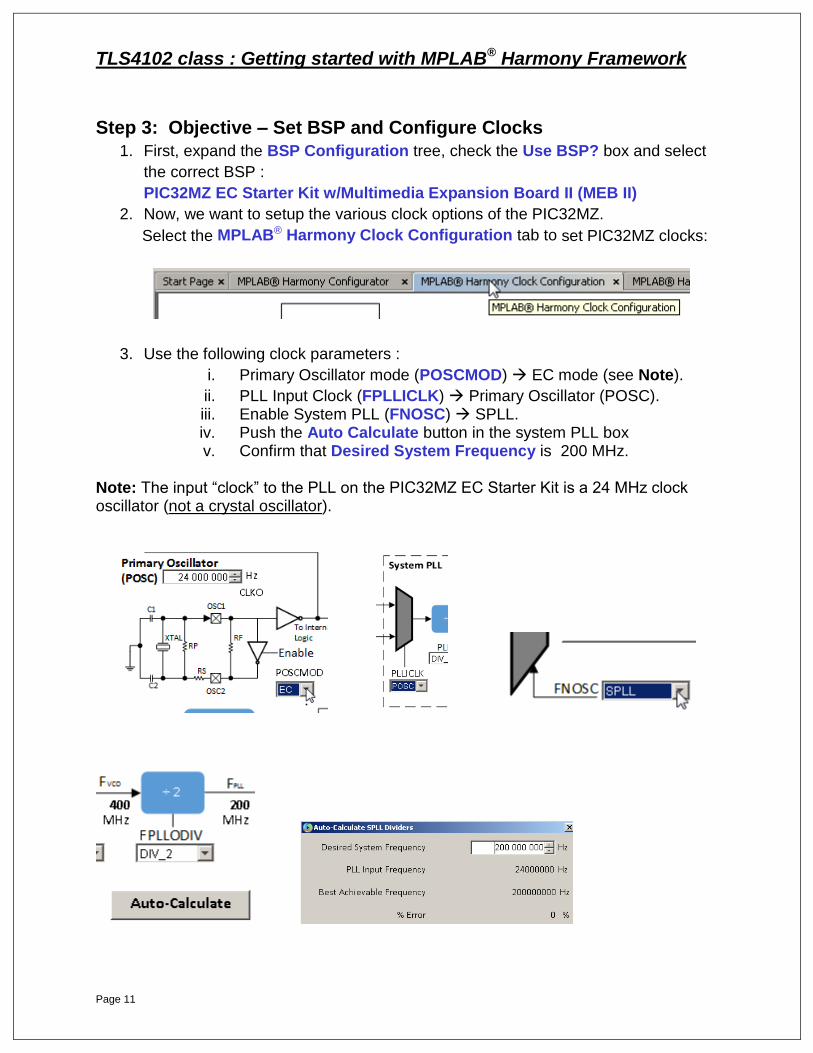
Step 3: Objective – Set BSP and Configure Clocks
1. First, expand the BSP Configuration tree, check the Use BSP? box and select
the correct BSP :
PIC32MZ EC Starter Kit w/Multimedia Expansion Board II (MEB II)
2. Now, we want to setup the various clock options of the PIC32MZ.
Select the MPLAB® Harmony Clock Configuration tab to set PIC32MZ clocks:
3. Use the following clock parameters :
i. Primary Oscillator mode (POSCMOD) EC mode (see Note).
ii. PLL Input Clock (FPLLICLK) Primary Oscillator (POSC). iii. Enable System PLL (FNOSC) SPLL. iv. Push the Auto Calculate button in the system PLL box v. Confirm that Desired System Frequency is 200 MHz.
Note: The input “clock” to the PLL on the PIC32MZ EC Starter Kit is a 24 MHz clock oscillator (not a crystal oscillator).

TLS4102 class : Getting started with MPLAB® Harmony Framework
Page 12
Step 3: Solution
1. Using MHC, enable and select the BSP as shown:
This value has been chosen to match the PIC32MZ hardware you are using.
2. Using MHC, configure the PIC32MZ2048ECH/(ECM)144 clocks:
a. Select the MPLAB® Harmony Clock Configuration tab.
b. Select the PIC32MZ Clock Configurations as shown (steps 1 thru 4)
TLS4102 class : Getting started with MPLAB® Harmony Framework
Page 13
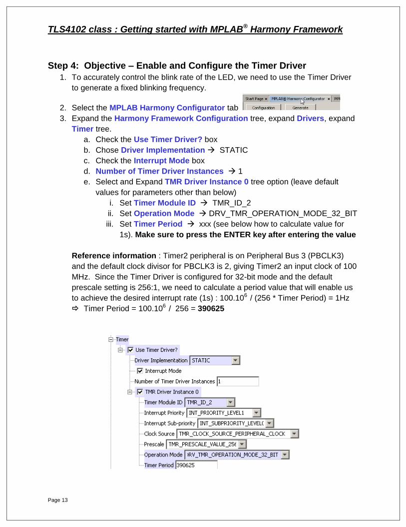
Step 4: Objective – Enable and Configure the Timer Driver
1. To accurately control the blink rate of the LED, we need to use the Timer Driver
to generate a fixed blinking frequency.
2. Select the MPLAB Harmony Configurator tab
3. Expand the Harmony Framework Configuration tree, expand Drivers, expand
Timer tree.
a. Check the Use Timer Driver? box
b. Chose Driver Implementation STATIC
c. Check the Interrupt Mode box
d. Number of Timer Driver Instances 1
e. Select and Expand TMR Driver Instance 0 tree option (leave default
values for parameters other than below)
i. Set Timer Module ID TMR_ID_2
ii. Set Operation Mode DRV_TMR_OPERATION_MODE_32_BIT
iii. Set Timer Period xxx (see below how to calculate value for
1s). Make sure to press the ENTER key after entering the value
Reference information : Timer2 peripheral is on Peripheral Bus 3 (PBCLK3)
and the default clock divisor for PBCLK3 is 2, giving Timer2 an input clock of 100
MHz. Since the Timer Driver is configured for 32-bit mode and the default
prescale setting is 256:1, we need to calculate a period value that will enable us
to achieve the desired interrupt rate (1s) : 100.106 / (256 * Timer Period) = 1Hz
Timer Period = 100.106 / 256 = 390625
TLS4102 class : Getting started with MPLAB® Harmony Framework
Page 14
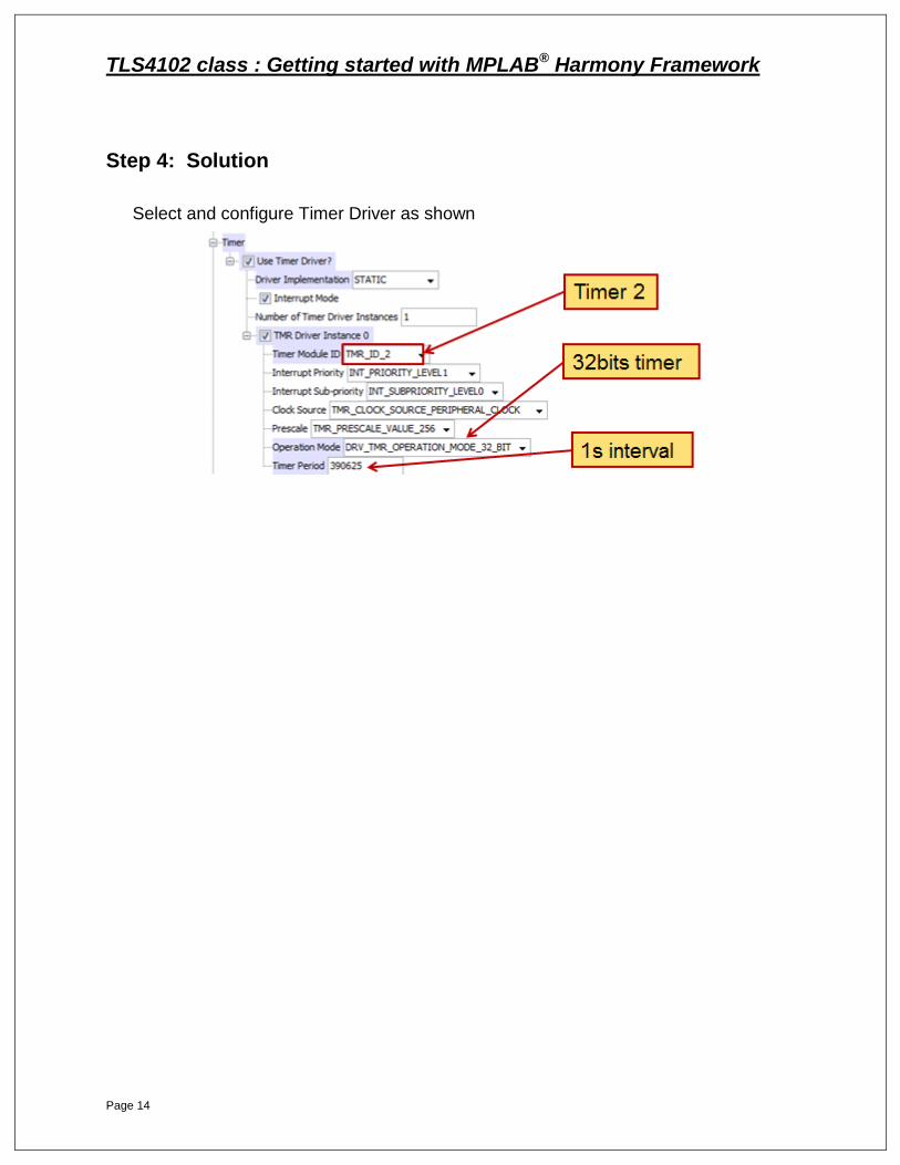
Step 4: Solution
Select and configure Timer Driver as shown
TLS4102 class : Getting started with MPLAB® Harmony Framework
Page 15
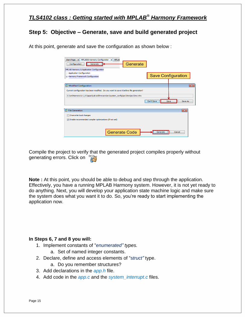
Step 5: Objective – Generate, save and build generated project
At this point, generate and save the configuration as shown below :
Compile the project to verify that the generated project compiles properly without generating errors. Click on Note : At this point, you should be able to debug and step through the application. Effectively, you have a running MPLAB Harmony system. However, it is not yet ready to do anything. Next, you will develop your application state machine logic and make sure the system does what you want it to do. So, you’re ready to start implementing the application now.
In Steps 6, 7 and 8 you will:
1. Implement constants of “enumerated” types.
a. Set of named integer constants.
2. Declare, define and access elements of “struct” type.
a. Do you remember structures?
3. Add declarations in the app.h file.
4. Add code in the app.c and the system_interrupt.c files.

TLS4102 class : Getting started with MPLAB® Harmony Framework
Page 16
C LANGUAGE REFRESHER : enumerated types and structures
Remember this refresher slide on “emum” and “struct” types for future reference in following labs. You may need it. It may come in handy.
MPLAB® X IDE EDITOR TIPS
a/ use the auto-complete function after typing a few characters : type CTRL+SPACE
b/ to navigate labels, functions, structures use hyperlink navigation : CTRL+”click”
i i

TLS4102 class : Getting started with MPLAB® Harmony Framework
Page 17
Step 6: Objective – Add Application States In this step we will add two named constants within an enum. These constants
are implemented in switch case statements as well as in an interrupt handler to determine the current application state as well as set the next application state for processing. In short, you are adding states to service in your application. 1. If not already opened or visible, open the Projects window ( Window > Projects )
2. If not expanded, expand the Lab1a project tree
3. If not expanded, expand Lab1a header files
4. Open the file app.h: (located under Header Files, in app folder)
a. In typedef enum “APP_STATES”, add two constants under
/* TODO: Define states used by the application state machine. */,:
i. APP_STATE_EVENT : why does it defaults to “1” ?
ii. APP_STATE_IDLE : what does this constant default to ?
5. These two “states” will be used in the following Steps 8 and 7 respectively.
TLS4102 class : Getting started with MPLAB® Harmony Framework
Page 18
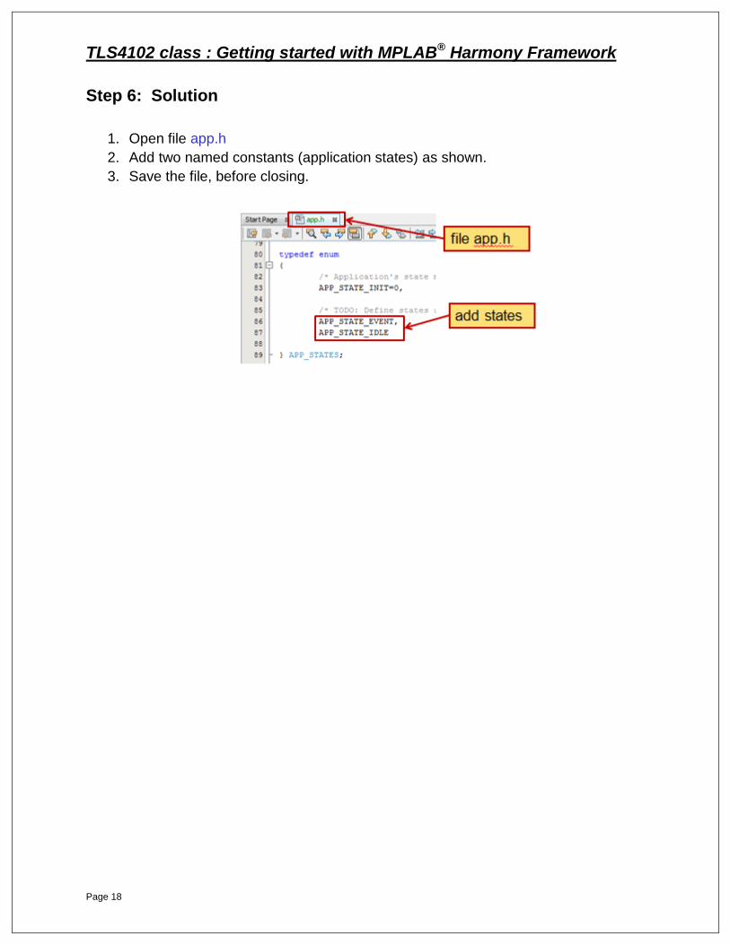
Step 6: Solution
1. Open file app.h
2. Add two named constants (application states) as shown.
3. Save the file, before closing.

TLS4102 class : Getting started with MPLAB® Harmony Framework
Page 19
Step 7: Objective – Start Timer Driver and set application states 1. Open file app.c: (located under Source Files in the app folder).
2. In the function APP_Tasks(), you will add code in three switch case statements: o In the existing case statement: APP_STATE_INIT
Add code to start Timer Driver Service Hint: to help you, look in the drv_timer_static.h file for the function prototypes :
Add code Update appData.state to IDLE
Hint : Look in app.h file fo find the various appData.state states
o Under /* TODO: implement your application state machine.*/, in case APP_STATE_EVENT state machine
Add code Toggle LED 3 on PIC32MZ SK
Hint: see file bsp_sys_init.c for BSP_LEDToggle(arg) function. You want to toggle LED 3

TLS4102 class : Getting started with MPLAB® Harmony Framework
Page 20
Add code to set appData.state back to IDLE (after
toggling the led). Look above for appData.state states. Do
not forget to also add a break; at the end of this 2nd case
o Finally, create a 3rd case statement for the remaining IDLE appData.state
APP_STATE_IDLE
This state does nothing so just add a break; inside ================================================================
Step 7: Solution
1. In file app.c:
a. Start Timer Driver service and set application state to IDLE.
b. Add case statement for EVENT state and add code .
i. Toggle LED 3 and then set app state to IDLE.
c. Add case statement for IDLE state. Exit.
d. Once done, save the file.
TLS4102 class : Getting started with MPLAB® Harmony Framework
Page 21
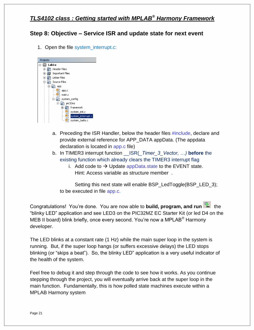
Step 8: Objective – Service ISR and update state for next event
1. Open the file system_interrupt.c:
a. Preceding the ISR Handler, below the header files #include, declare and
provide external reference for APP_DATA appData. (The appdata
declaration is located in app.c file)
b. In TIMER3 interrupt function __ISR(_Timer_3_Vector, …) before the
existing function which already clears the TIMER3 interrupt flag
i. Add code to Update appData.state to the EVENT state.
Hint: Access variable as structure member .
Setting this next state will enable BSP_LedToggle(BSP_LED_3);
to be executed in file app.c.
Congratulations! You’re done. You are now able to build, program, and run the
“blinky LED” application and see LED3 on the PIC32MZ EC Starter Kit (or led D4 on the
MEB II board) blink briefly, once every second. You’re now a MPLAB® Harmony
developer.
The LED blinks at a constant rate (1 Hz) while the main super loop in the system is
running. But, if the super loop hangs (or suffers excessive delays) the LED stops
blinking (or “skips a beat”). So, the blinky LED” application is a very useful indicator of
the health of the system.
Feel free to debug it and step through the code to see how it works. As you continue
stepping through the project, you will eventually arrive back at the super loop in the
main function. Fundamentally, this is how polled state machines execute within a
MPLAB Harmony system
TLS4102 class : Getting started with MPLAB® Harmony Framework
Page 22
Note: Don’t be surprised if you cannot step into the PLIB function calls. They are
implemented as inline functions and source code is provided in the MPLAB® Harmony
installation. It is possible to rebuild the PLIB, converting them to actual function calls,
without optimizations and with debug symbols enabled, so that you can step through
them. But, they are generally very simple functions that provide access to peripheral
Special Function Registers (SFRs) through an abstracted C-language function call
interface that remains the same on all parts on which they are supported.
Time permitting; explore the Lab1a project files and folders. Observe that the
project consists of several “logical” folders within the MPLAB® X IDE and several
physical folders on disk. This organization is used consistently by MPLAB Harmony
applications to keep the files well organized. The MPLAB® X IDE separates header
(.h) files from source (.c) files, so the logical folder structure duplicates (with some
small differences) the physical folder structure on disk under both the Header Files
and Source Files top-level logical folders. In most cases, the folders on disk
correspond directly to the logical folders in the MPLAB® X IDE, but the header files and
source files are not separated on disk as they are in the MPLAB X IDE logical folder
tree. Also, the app logical folder corresponds to the src folder on disk.
The application’s src folder contains the main.c file as well as the app.c and
app.h files that implement the application. (Note: By convention, the main.c file is
identical for all MPLAB® Harmony applications.) The system_config folder normally
holds one or more configuration-specific folders (system_config\PIC32MZ in this
case) that each contains a complete set of configuration files for an MPLAB Harmony
application.
=========================================================
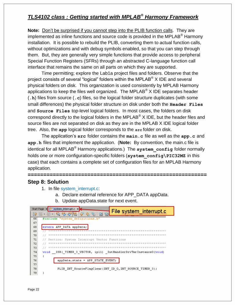
Step 8: Solution
1. In file system_interrupt.c:
a. Declare external reference for APP_DATA appData.
b. Update appData.state for next event.

TLS4102 class : Getting started with MPLAB® Harmony Framework
Page 23
LAB 1b: Adding UART
Communication
TLS4102 class : Getting started with MPLAB® Harmony Framework
Page 24
LAB 1b: Adding UART Communication
Purpose: After completing Lab 1b, you will have an introduction to the UART Static Driver and
continue your learning with the capabilities of the MPLAB® Harmony Configurator.
Overview:
In this lab, you will add a UART to your existing project. The lab result will show a
character being transmitted out on the UART TX, every one second, which is the same
toggle rate of the LED3 on the PIC32MZ EC Starter Kit. The lab will demonstrate how
easy it is to both enable and configure new PIC32 features using MHC.
Procedure:
1. First, close the Lab1a project and open the Lab1b project :
File > Close Project (Lab1a)
File > Open Project > C:\microchip\harmony\v1_03\apps\Lab1b\firmware\Lab1b.X
2. We must set Lab1b as Main Project to be able to use MHC : Set as Main Project
3. We need to enable MHC : Tools > Embedded > MPLAB Harmony Configurator
4. For Lab 1b, there are six steps, shown in Part 1 and Part 2. All six steps must be
completed before you will be ready to build, download, and run the application.
Each step has a short list of requirements to guide you in the solution
development. Following each set of requirements, answers are provided. You
can refer to the answers as needed.
Part 1: With MHC, add UART Functionality
Step 1 – With MHC, add USART Static Driver
Step 2 – With Harmony Pin Table feature, connect UART2 to pin 61 to enable UART TX
Step 3 – With MHC, Generate Code
Step 4 – With MHC, Merge Auto-Generated and custom code
Step 5 – Using MHC help, find USART API for sending a byte
Part 2: Add Application code
Step 6 – Add code to send USART byte

TLS4102 class : Getting started with MPLAB® Harmony Framework
Page 25
Step 1: Objective – Enable and Configure the USART Driver
1. Select the MPLAB® Harmony Configurator tab
2. Expand the Harmony Framework Configuration tree, expand Drivers, expand
USART tree.
a. Check the Use USART Driver? box
b. Select Driver Implementation STATIC
c. Make sure that Interrupt Mode checkbox is deselected.
d. Number of USART Instances 1 (default)
i. Select and Expand USART Driver Instance 0
ii. Set USART Module ID USART_ID_2
iii. Disable USART RX uncheck Enable RX
==================================================================
Step 1: Solution
1. Select and Configure USART TX Driver as shown.
2. Ensure that Interrupt Mode is deselected.
3. Disable USART RX.
TLS4102 class : Getting started with MPLAB® Harmony Framework
Page 26
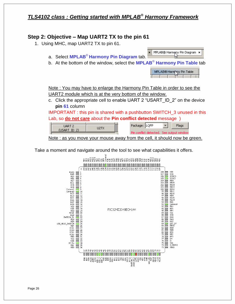
Step 2: Objective – Map UART2 TX to the pin 61
1. Using MHC, map UART2 TX to pin 61.
a. Select MPLAB® Harmony Pin Diagram tab.
b. At the bottom of the window, select the MPLAB® Harmony Pin Table tab
Note : You may have to enlarge the Harmony Pin Table in order to see the
UART2 module which is at the very bottom of the window.
c. Click the appropriate cell to enable UART 2 “USART_ID_2” on the device
pin 61 column
IMPORTANT : this pin is shared with a pushbutton SWITCH_3 unused in this
Lab, so do not care about the Pin conflict detected message )
Note : as you move your mouse away from the cell, it should now be green.
Take a moment and navigate around the tool to see what capabilities it offers.
TLS4102 class : Getting started with MPLAB® Harmony Framework
Page 27
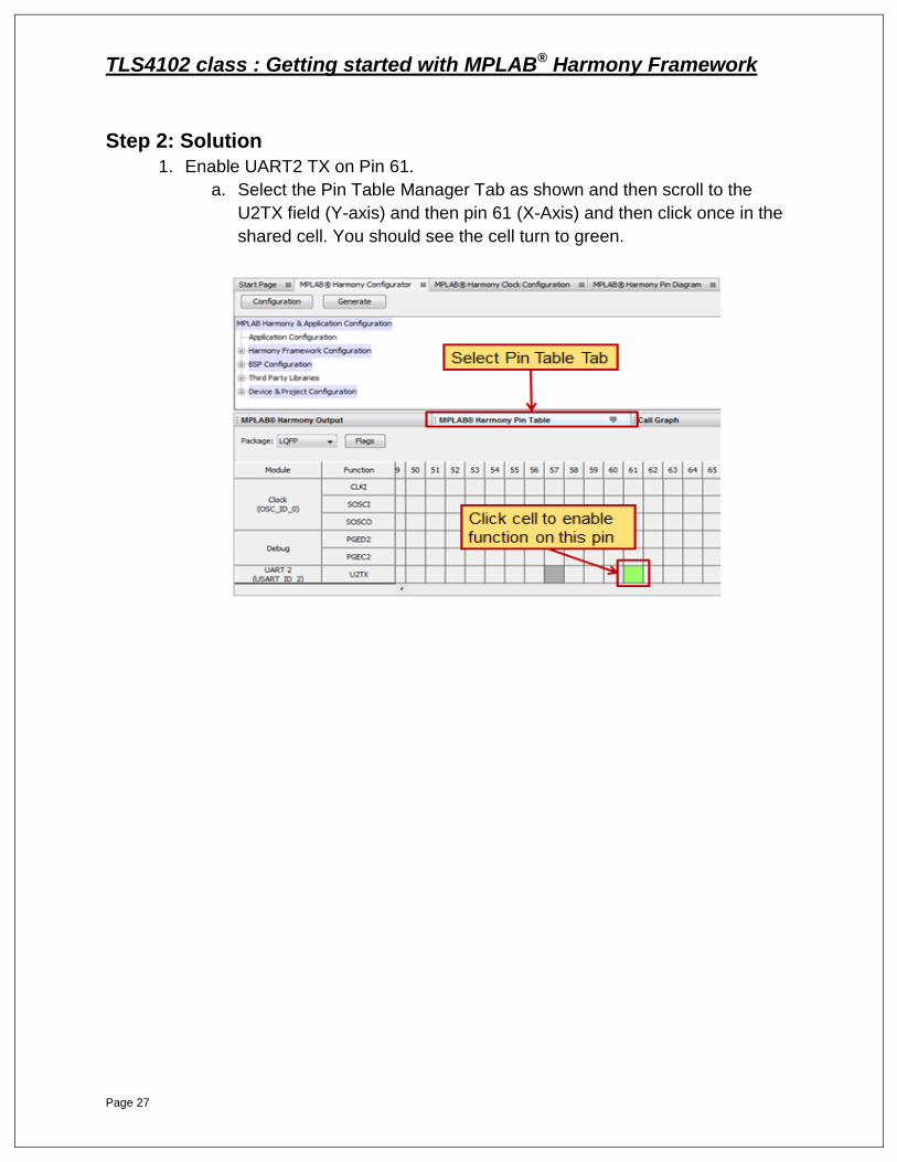
Step 2: Solution
1. Enable UART2 TX on Pin 61.
a. Select the Pin Table Manager Tab as shown and then scroll to the
U2TX field (Y-axis) and then pin 61 (X-Axis) and then click once in the
shared cell. You should see the cell turn to green.

TLS4102 class : Getting started with MPLAB® Harmony Framework
Page 28
Step 3: At this point generate and save the configuration as shown
First, select the MPLAB® Harmony Configurator tab and follow instructions :
Step 4: Merge Auto-Generated and custom code
The “DIF” window opens up and shows the differences between auto-generated
code and the manual modifications we just made in previous steps.
This tool is a great way to check and accept the code changes you just made against
the previous source. We have added the USART functionality to the existing running
MPLAB Harmony system.
Build the project to make sure there is no error at this step. Push the icon
Now, you’re ready to start implementing the application code.
TLS4102 class : Getting started with MPLAB® Harmony Framework
Page 29
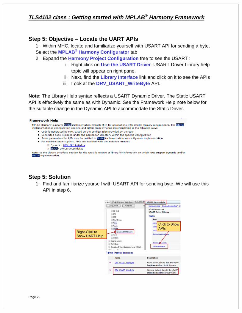
Step 5: Objective – Locate the UART APIs
1. Within MHC, locate and familiarize yourself with USART API for sending a byte.
Select the MPLAB® Harmony Configurator tab
2. Expand the Harmony Project Configuration tree to see the USART :
i. Right click on Use the USART Driver. USART Driver Library help
topic will appear on right pane.
ii. Next, find the Library Interface link and click on it to see the APIs
iii. Look at the DRV_USART_WriteByte API.
Note: The Library Help syntax reflects a USART Dynamic Driver. The Static USART
API is effectively the same as with Dynamic. See the Framework Help note below for
the suitable change in the Dynamic API to accommodate the Static Driver.
Step 5: Solution
1. Find and familiarize yourself with USART API for sending byte. We will use this
API in step 6.

TLS4102 class : Getting started with MPLAB® Harmony Framework
Page 30
Step 6: Objective – Write byte to UART
1. Under Source Files > app subfolder, open the file app.c:
a. In function APP_Tasks(), we need to add code in one switch case
statement to Transmit one byte over the UART :
i. case APP_STATE_EVENT:
1. Add code to Send byte character ‘a’ as function argument.
a. Hint: You just looked up the API for this function.
b. Remember you’re using USART Driver Instance 0
(static) .
Congratulations! You’re almost there. Before proceeding just two more quick items:
1. Ensure the UART-to-USB adaptor is connected to the J2 header on the MEB II.
2. Connect a USB cable to the PC and launch Tera Term Pro or any other terminal
emulator with these settings: 9600 baud, 8, N, 1. ( Setup > Serial port > …)
You are now able to build, program, and run the application and see
LED3 on the PIC32MZ Starter Kit blink once every 2 seconds (Led D4 on MEB II
board) and also see the character ‘a’ received and displayed on the terminal
each and every second.
=================================================================
Step 6 : Solution
1. Write a byte (character ‘a’) for each and every event.
TLS4102 class : Getting started with MPLAB® Harmony Framework
Page 31
LAB 2a: Adding Graphics
Library

TLS4102 class : Getting started with MPLAB® Harmony Framework
Page 32
LAB 2a: Adding Graphics Library
Purpose: After completing Lab 2a, you will have an understanding of how to use MHC to add and
enable graphics into your application. We will keep the graphics simple and basic for
this lab. You can build on this foundational knowledge at a later time.
Overview:
In this lab, you will start with your previous project after you completed Lab 1b.
Using MHC, you will select and enable a Graphics Library application and integrate it
into Lab 1b.
Procedure:
First, close the Lab1b project and open the Lab2a project :
File > Close Project (Lab1b)
File > Open Project > C:\microchip\harmony\v1_03\apps\Lab2a\firmware\Lab2a.X
We must set Lab2a as Main Project to be able to use MHC : Set as Main Project
We need to enable MHC : Tools > Embedded > MPLAB Harmony Configurator
For Lab 2a, there are six steps, as follows. All six steps must be completed
before you will be ready to build, download and run the application.
Each step has a short list of requirements to guide you in the solution
development. Following each set of requirements, answers are provided. You
can refer to the answers as needed.
With MHC, add Graphics Functionality
Step 1 – Add pre-built GRC generated files to the project
Step 2 – With MHC, enable Graphics into your project
Step 3 – With MHC, Generate Code
Step 4 – With MHC, Merge Auto-Generated and custom code
Step 5 – Add code: Initialize screen, draw box, and add text
Step 6 – Add code: Toggle rectangle, fill color as LED changes
TLS4102 class : Getting started with MPLAB® Harmony Framework
Page 33
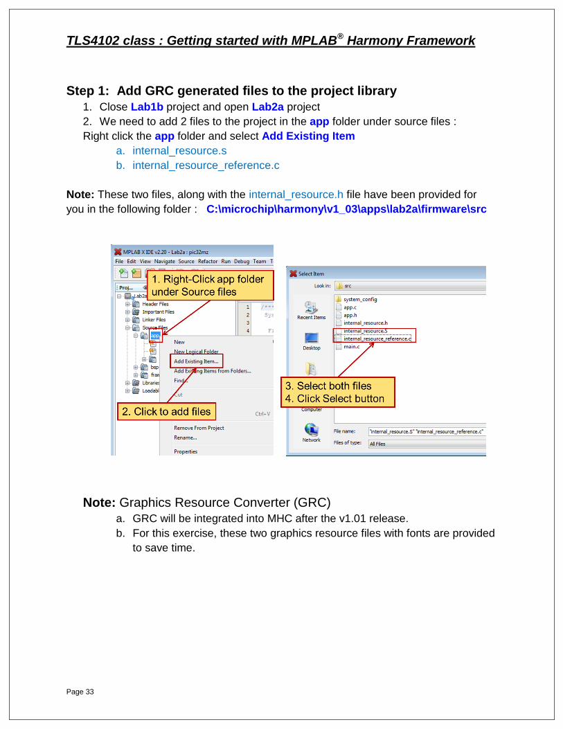
Step 1: Add GRC generated files to the project library
1. Close Lab1b project and open Lab2a project
2. We need to add 2 files to the project in the app folder under source files :
Right click the app folder and select Add Existing Item
a. internal_resource.s
b. internal_resource_reference.c
Note: These two files, along with the internal_resource.h file have been provided for
you in the following folder : C:\microchip\harmony\v1_03\apps\lab2a\firmware\src
Note: Graphics Resource Converter (GRC)
a. GRC will be integrated into MHC after the v1.01 release.
b. For this exercise, these two graphics resource files with fonts are provided
to save time.
TLS4102 class : Getting started with MPLAB® Harmony Framework
Page 34
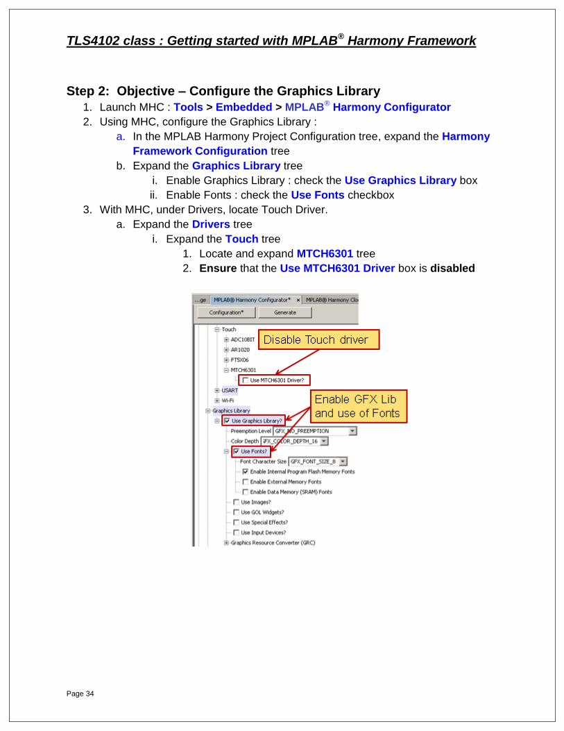
Step 2: Objective – Configure the Graphics Library
1. Launch MHC : Tools > Embedded > MPLAB® Harmony Configurator
2. Using MHC, configure the Graphics Library :
a. In the MPLAB Harmony Project Configuration tree, expand the Harmony
Framework Configuration tree
b. Expand the Graphics Library tree
i. Enable Graphics Library : check the Use Graphics Library box
ii. Enable Fonts : check the Use Fonts checkbox
3. With MHC, under Drivers, locate Touch Driver.
a. Expand the Drivers tree
i. Expand the Touch tree
1. Locate and expand MTCH6301 tree
2. Ensure that the Use MTCH6301 Driver box is disabled
TLS4102 class : Getting started with MPLAB® Harmony Framework
Page 35
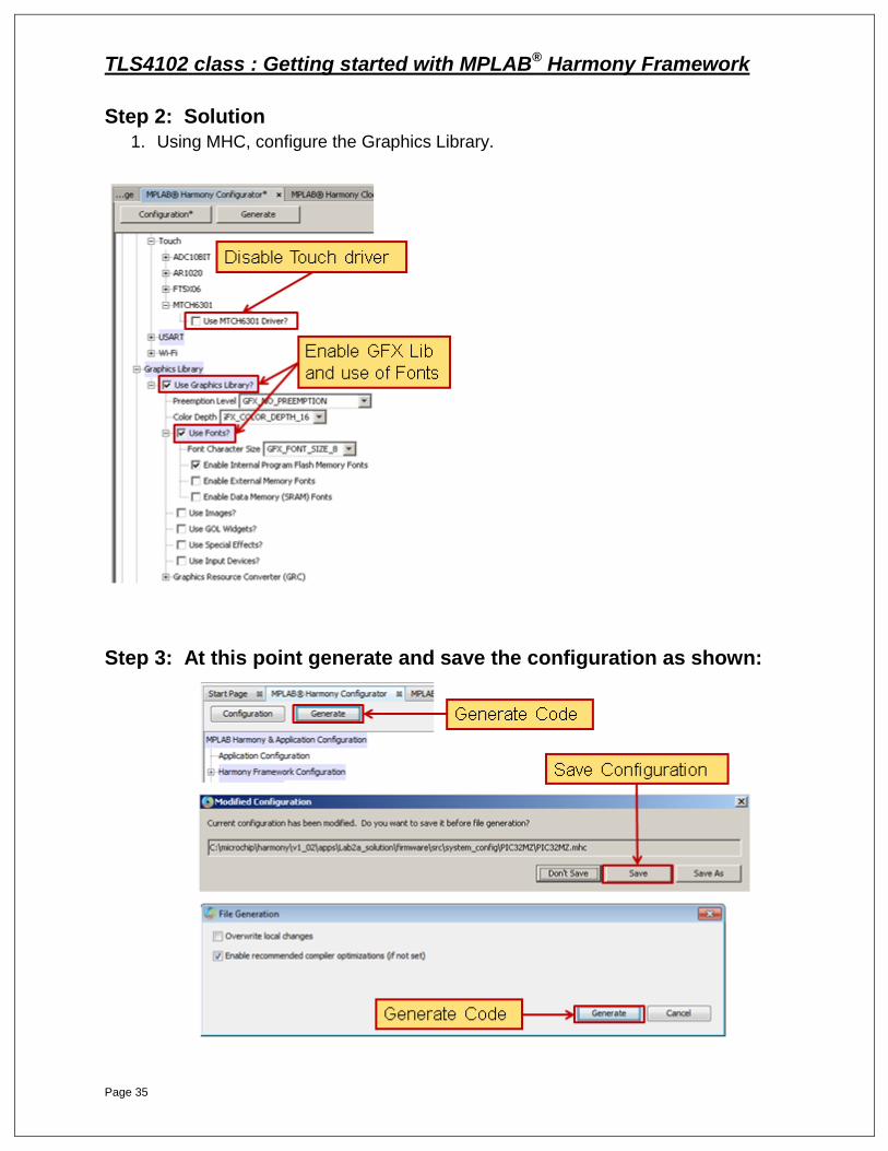
Step 2: Solution
1. Using MHC, configure the Graphics Library.
Step 3: At this point generate and save the configuration as shown:
TLS4102 class : Getting started with MPLAB® Harmony Framework
Page 36
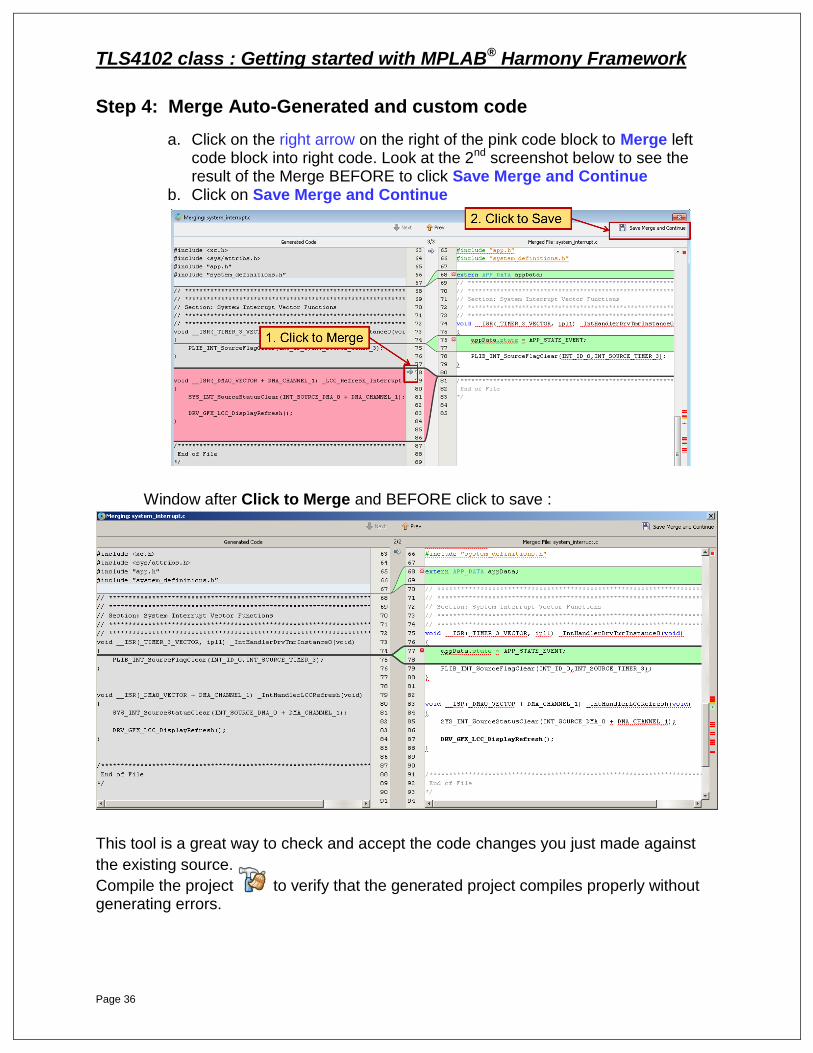
Step 4: Merge Auto-Generated and custom code
a. Click on the right arrow on the right of the pink code block to Merge left code block into right code. Look at the 2nd screenshot below to see the result of the Merge BEFORE to click Save Merge and Continue
b. Click on Save Merge and Continue
Window after Click to Merge and BEFORE click to save :
This tool is a great way to check and accept the code changes you just made against
the existing source.
Compile the project to verify that the generated project compiles properly without generating errors.

TLS4102 class : Getting started with MPLAB® Harmony Framework
Page 37
Step 5: Objectives – Initialize the screen, draw a box and display text
First you need to #include internal_resource.h file at the beginning of app.c file.
In this step you will update one switch case statements in file app.c.
For all GFX Library API help, refer to the integrated GFX Library Help window,
starting at the Library Interface top level help section.
To perform this step you can either look for the functions and their parameters in the
documentation or copy/paste the necessary code from following pages.
Open file app.c, in app folder, locate case statement APP_STATE_INIT and add code :
1. Wait for GFX Library to initialize GFX_Status( argument ); i. This function provides the current status of the GFX Module.
ii. See System and Client Interfaces (Help window)
Before executing the code within the APP_STATE_INIT case, we need to wait for GFX
Library to initialize but we don’t want to BLOCK the appData.state state machine until it
gets initialized : use GFX_Status( argument ) function. The argument is the object
index which was returned by GFX_Initialize (use MPLAB X search to find it).
2. Set screen color GFX_ColorSet( arg1, arg2 );
After the existing DRV_TMR0_Start(); function add GFX_ColorSet( arg1, arg2 ); i. This function sets the color to be used to render primitive shapes & text. Color to use is
GREEN (argument2). see Note1 below
ii. Graphics Primitive Layer > Graphics Primitive Layer API > Color Functions (Help window)
iii. Clear the screen GFX_ScreenClear( argument );Graphics Primitive Layer >
Graphics Primitive Layer API > Initialize Functions (Help window)
This function clears the screen with current color and sets cursor position to (0, 0).
3. Set screen color GFX_ColorSet(arg1, arg2 ); i. Color to use is WHITE (argument2). (*) see Note1 below
ii. Graphics Primitive Layer > Graphics Primitive Layer API > Color Functions (Help window)
4. Draw rectangle w/white box GFX_RectangleDraw(arg1, arg2, arg3, arg4,arg5);
i. This function renders a rectangular shape using the given left, top, right and bottom
parameters to define the shape dimension. Use 40,20,60,80 for arg2 to arg5.
ii. Graphics Primitive Layer > Graphics Primitive Layer API > Polygon Rendering Functions help
5. Set Display Font GFX_FontSet(arg1,arg2);
i. This function sets the current font used to render strings and characters
ii. See Graphics Primitive Layer API Text Rendering Functions (Help window)
TLS4102 class : Getting started with MPLAB® Harmony Framework
Page 38
For arg2, we need to provide a pointer to the Font which will be used : &My_Font 6. Display “D4” name under box GFX_TextStringDraw(arg1, arg2, arg3, arg4,arg5);
i. This function renders the given string of character using the currently set font, and
color to the location defined by the given x, y position. Use 40, 90 for the x, y
positions. As we want to display “D4” under the box just drawn previously
ii. See Graphics Primitive Layer API Text Rendering Functions (help window)
===============================================================================
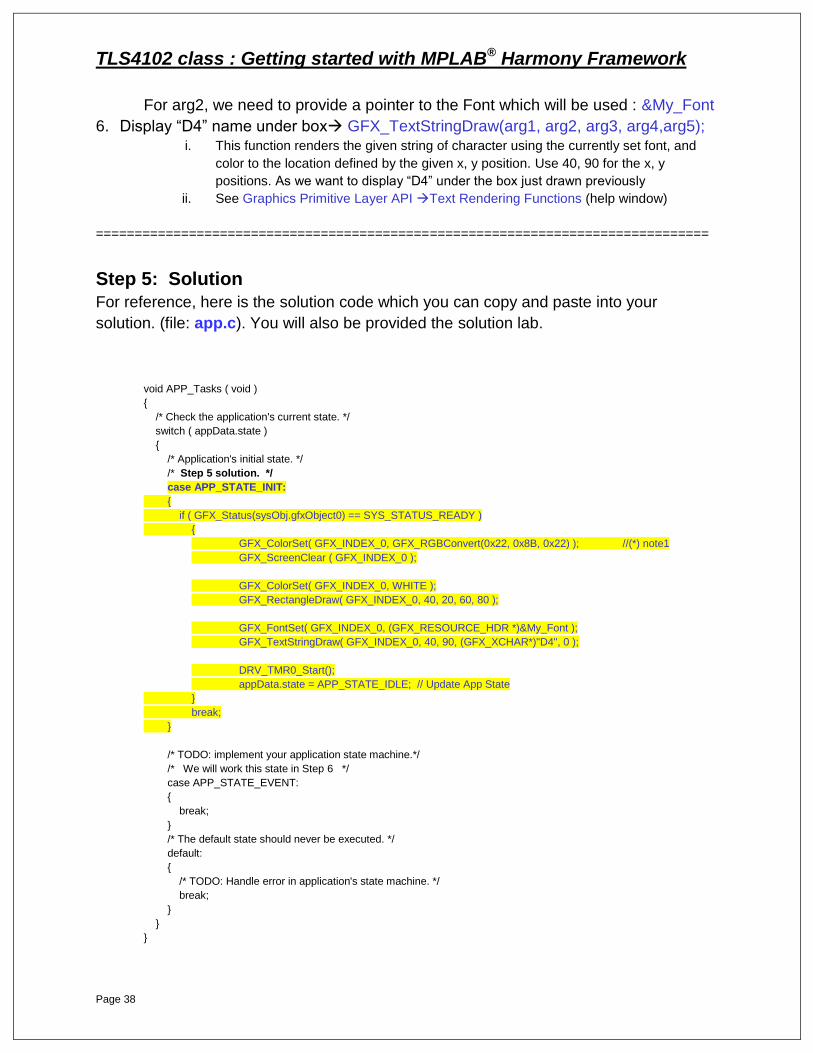
Step 5: Solution
For reference, here is the solution code which you can copy and paste into your
solution. (file: app.c). You will also be provided the solution lab.
void APP_Tasks ( void )
{
/* Check the application's current state. */
switch ( appData.state )
{
/* Application's initial state. */
/* Step 5 solution. */
case APP_STATE_INIT:
{
if ( GFX_Status(sysObj.gfxObject0) == SYS_STATUS_READY )
{ GFX_ColorSet( GFX_INDEX_0, GFX_RGBConvert(0x22, 0x8B, 0x22) ); //(*) note1
GFX_ScreenClear ( GFX_INDEX_0 );
GFX_ColorSet( GFX_INDEX_0, WHITE );
GFX_RectangleDraw( GFX_INDEX_0, 40, 20, 60, 80 );
GFX_FontSet( GFX_INDEX_0, (GFX_RESOURCE_HDR *)&My_Font );
GFX_TextStringDraw( GFX_INDEX_0, 40, 90, (GFX_XCHAR*)"D4", 0 );
DRV_TMR0_Start(); appData.state = APP_STATE_IDLE; // Update App State
}
break;
}
/* TODO: implement your application state machine.*/
/* We will work this state in Step 6 */
case APP_STATE_EVENT:
{ break;
}
/* The default state should never be executed. */
default:
{
/* TODO: Handle error in application's state machine. */
break;
}
}
}

TLS4102 class : Getting started with MPLAB® Harmony Framework
Page 39
TLS4102 class : Getting started with MPLAB® Harmony Framework
Page 40
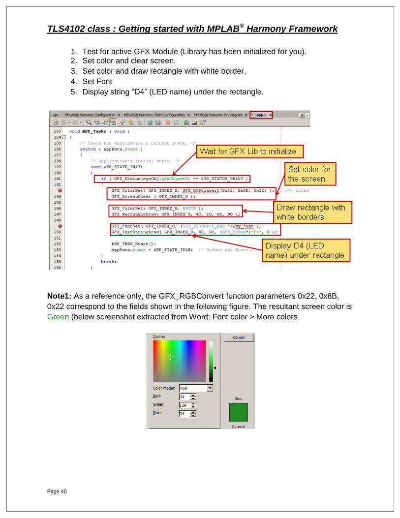
1. Test for active GFX Module (Library has been initialized for you). 2. Set color and clear screen.
3. Set color and draw rectangle with white border.
4. Set Font
5. Display string “D4” (LED name) under the rectangle.
Note1: As a reference only, the GFX_RGBConvert function parameters 0x22, 0x8B,
0x22 correspond to the fields shown in the following figure. The resultant screen color is
Green (below screenshot extracted from Word: Font color > More colors
TLS4102 class : Getting started with MPLAB® Harmony Framework
Page 41
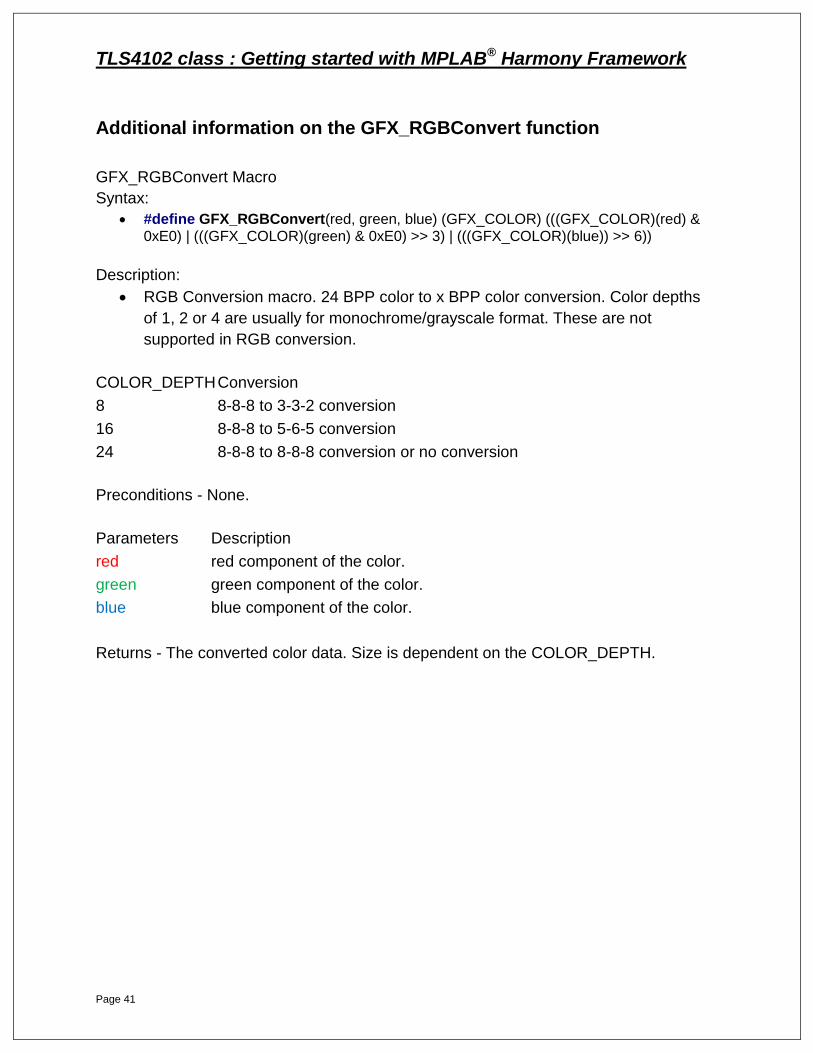
Additional information on the GFX_RGBConvert function
GFX_RGBConvert Macro
Syntax:
#define GFX_RGBConvert(red, green, blue) (GFX_COLOR) (((GFX_COLOR)(red) & 0xE0) | (((GFX_COLOR)(green) & 0xE0) >> 3) | (((GFX_COLOR)(blue)) >> 6))
Description:
RGB Conversion macro. 24 BPP color to x BPP color conversion. Color depths
of 1, 2 or 4 are usually for monochrome/grayscale format. These are not
supported in RGB conversion.
COLOR_DEPTH Conversion
8 8-8-8 to 3-3-2 conversion
16 8-8-8 to 5-6-5 conversion
24 8-8-8 to 8-8-8 conversion or no conversion
Preconditions - None.
Parameters Description
red red component of the color.
green green component of the color.
blue blue component of the color.
Returns - The converted color data. Size is dependent on the COLOR_DEPTH.

TLS4102 class : Getting started with MPLAB® Harmony Framework
Page 42
Step 6: Objectives – Toggle rectangle, fill color as LED toggles
In this step you will update one switch case statements in the app.c file.
As with Step 3, refer to the integrated GFX Library Help window, starting at the
Library Interface top level help section.
To perform this step you can either look for the functions and their parameters in the
documentation or copy/paste the necessary code from following pages.
Open file app.c, and locate case statement APP_STATE_EVENT :
After the line DRV_USART0_WriteByte('a'); add if-else code to:
1. If BSP LED state is true, then Test BSP LED State BSP_LEDStateGet( arg1 ); i. This function returns the present state of the LED. Hint: we are talking about BSP_LED_3.
ii. See Board Support Package Help Library Interface LED Control Functions
BSP_LEDStateGet Function.
2. Set screen color GFX_ColorSet( arg1, arg2 );
i. This function sets the color to be used to render primitive shapes & text. Color to use is
BRIGHTRED
ii. See Graphics Primitive Layer API Color Functions
3. Draw Filled Rectangle GFX_RectangleFillDraw(arg1, arg2, arg3, arg4,arg5); i. This function renders a filled rectangular shape with the currently set fill style (see
GFX_FILL_STYLE) with the given left, top, right, and bottom parameters to define the shape
dimension. Use parameters 41, 21, 59, 79, respectively. These coordinates reflect the
“inside” of the rectangle drawn in Step 3.
ii. See Graphics Primitive Layer API Polygon Fill Rendering Functions
4. Else test is false ….. (as in LED is not on)
5. Set screen color GFX_ColorSet( arg1, arg2 ); i. This function sets the color to be used to render primitive shapes & text.
ii. See Graphics Primitive Layer API Color Functions
6. Draw Filled Rectangle GFX_RectangleFillDraw(arg1, arg2, arg3, arg4,arg5);
i. This function renders a filled rectangular shape with the currently set fill style (see
GFX_FILL_STYLE) with the given left, top, right, and bottom parameters to define the shape
dimension. Use parameters 41, 21, 59, 79, respectively. These coordinates reflect the
“inside” of the rectangle drawn in Step 3.
ii. See Graphics Primitive Layer API Polygon Fill Rendering Functions

TLS4102 class : Getting started with MPLAB® Harmony Framework
Page 43
For reference, here is the answer code (file: app.c). The solution of this lab is provided
in the lab2a_solution project where you can copy paste from the solution app.c file
/* Step 6 solution. */
case APP_STATE_EVENT:
{
BSP_LEDToggle( BSP_LED_3 );
DRV_USART0_WriteByte( 'a' );
if ( BSP_LEDStateGet(BSP_LED_3) == BSP_LED_STATE_ON )
{
GFX_ColorSet( GFX_INDEX_0, BRIGHTRED );
GFX_RectangleFillDraw( GFX_INDEX_0, 41, 21, 59, 79 );
}
else
{
GFX_ColorSet( GFX_INDEX_0, GFX_RGBConvert(0x22, 0x8B, 0x22) );
GFX_RectangleFillDraw( GFX_INDEX_0, 41, 21, 59, 79 );
}
appData.state = APP_STATE_IDLE;
break;
}
/* The default state should never be executed. */
default:
{
/* TODO: Handle error in application's state machine. */
break;
}
TLS4102 class : Getting started with MPLAB® Harmony Framework
Page 44
Step 6: Solution
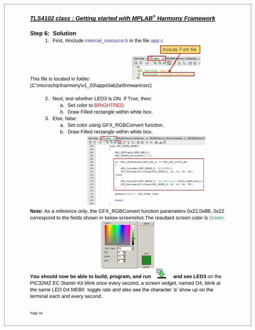
1. First, #include internal_resource.h in the file app.c
This file is located in folder:
(C:\microchip\harmony\v1_03\apps\lab2a\firmware\src)
2. Next, test whether LED3 is ON. If True, then:
a. Set color to BRIGHTRED.
b. Draw Filled rectangle within white box.
3. Else, false:
a. Set color using GFX_RGBConvert function,
b. Draw Filled rectangle within white box,
Note: As a reference only, the GFX_RGBConvert function parameters 0x22,0x8B, 0x22
correspond to the fields shown in below screenshot.The resultant screen color is Green.
You should now be able to build, program, and run and see LED3 on the
PIC32MZ EC Starter Kit blink once every second, a screen widget, named D4, blink at
the same LED D4 MEBII toggle rate and also see the character ‘a’ show up on the
terminal each and every second.

TLS4102 class : Getting started with MPLAB® Harmony Framework
Page 45
TLS4102 class : Getting started with MPLAB® Harmony Framework
Page 46
LAB 2b: Multi-stack –
Creating Complex MPLAB®
Harmony Projects
TLS4102 class : Getting started with MPLAB® Harmony Framework
Page 47
LAB 2b: Multi-Stack - Creating Complex MPLAB®
Harmony Projects
Purpose: After completing Lab 2b, you will have gained additional experience using MHC to add,
enable, and configure PIC32 Harmony USB Host MSD and File System Library
components.
Procedure:
In Lab 2b, you will add Harmony USB Host MSD and File System components to
the previous project. When the final application is running and you insert a USB
Pen Drive into the PIC32MZ EC Starter Kit, a stored message is read from the
Pen Drive and displayed on the MEB II glass and also transmitted on UART TX.
In this lab you will become familiar with several USB Host MSD and File System
APIs and how to bring these elements into a system with MHC.
Also, you will understand how to create a second application configuration and
how to process the application states within the overall application.
There are 12 steps in Lab 2b. All 12 steps must be completed before you will
be ready to build, download, and run the application.
Here are the steps you will work through:
Adding USB Host MSD and File Systems Components
Step 1 – Enable USB Host with MSD
Step 2 – With MHC, Generate Code, Merge Auto-Generated and custom code
Step 3 – With MHC Reconfigure Timer Services
Step 4 – With MHC, Generate Code, Merge Auto-Generated and custom code
Step 5 – With MHC, create two Application Configurations
Step 6 – With MHC, Generate Code, Merge Auto-Generated and custom code
Step 7 – Add USB and MSD callback functions
Step 8 – Start Timer Service as 1 second event Step 9 – Use Timer Service as 1 second event
Step 10 – Add USB MSD application states
Step 11 – Add USB MSD application state execution code
Step 12 – Update Initialization code in app.c
TLS4102 class : Getting started with MPLAB® Harmony Framework
Page 48
Each step has a short list of actions to guide you in the solution development.
Following each set of requirements, answers are provided. You can refer to the
answers as needed
Ensure that the USB debugger cable is attached and the correct hardware and
language tools are selected.
All three of these “applications” (Graphics, USB Host MSD and File System
Libraries) are running, effectively independently within the MPLAB Harmony
system with no conflicts.
PROCEDURE
1. First, close the Lab2a project and open the Lab2b project :
File > Close Project (Lab2a)
File > Open Project > C:\microchip\harmony\v1_03\apps\Lab2b\firmware\Lab2b.X
We must set Lab2b as Main Project to be able to use MHC : Set as Main Project
We need to enable MHC : Tools > Embedded > MPLAB Harmony Configurator
TLS4102 class : Getting started with MPLAB® Harmony Framework
Page 49
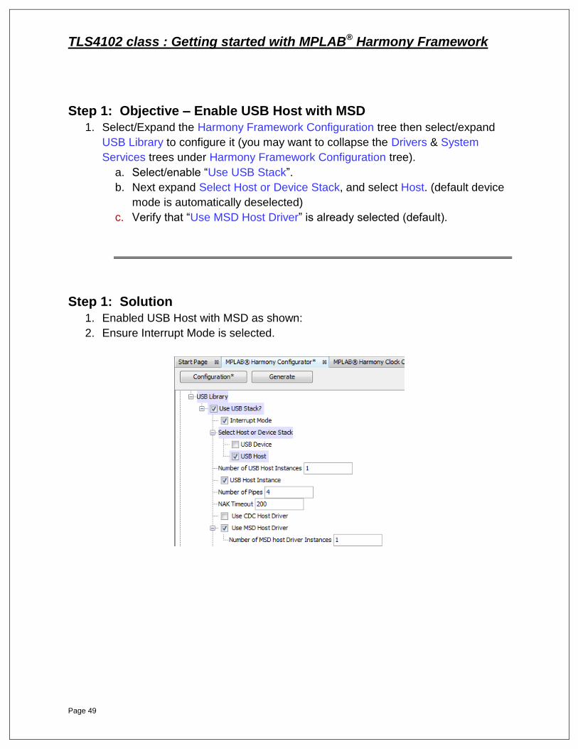
Step 1: Objective – Enable USB Host with MSD
1. Select/Expand the Harmony Framework Configuration tree then select/expand
USB Library to configure it (you may want to collapse the Drivers & System
Services trees under Harmony Framework Configuration tree).
a. Select/enable “Use USB Stack”.
b. Next expand Select Host or Device Stack, and select Host. (default device
mode is automatically deselected)
c. Verify that “Use MSD Host Driver” is already selected (default).
Step 1: Solution
1. Enabled USB Host with MSD as shown:
2. Ensure Interrupt Mode is selected.
TLS4102 class : Getting started with MPLAB® Harmony Framework
Page 50
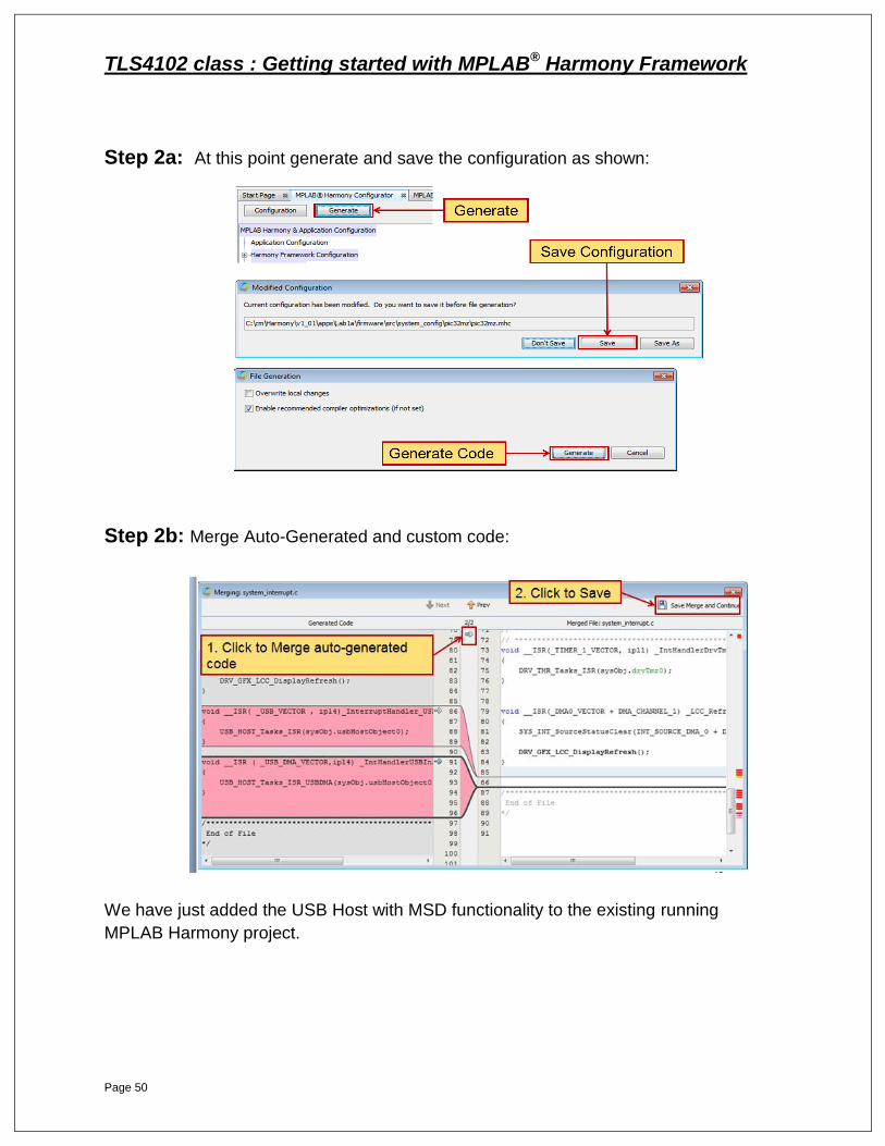
Step 2a: At this point generate and save the configuration as shown:
Step 2b: Merge Auto-Generated and custom code:
We have just added the USB Host with MSD functionality to the existing running
MPLAB Harmony project.
TLS4102 class : Getting started with MPLAB® Harmony Framework
Page 51
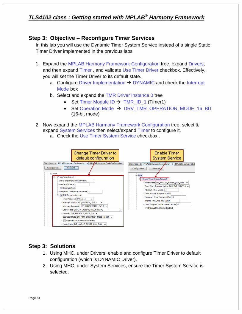
Step 3: Objective – Reconfigure Timer Services
In this lab you will use the Dynamic Timer System Service instead of a single Static
Timer Driver implemented in the previous labs.
1. Expand the MPLAB Harmony Framework Configuration tree, expand Drivers,
and then expand Timer , and validate Use Timer Driver checkbox. Effectively,
you will set the Timer Driver to its default state.
a. Configure Driver Implementation DYNAMIC and check the Interrupt
Mode box
b. Select and expand the TMR Driver Instance 0 tree
Set Timer Module ID TMR_ID_1 (Timer1)
Set Operation Mode DRV_TMR_OPERATION_MODE_16_BIT (16-bit mode)
2. Now expand the MPLAB Harmony Framework Configuration tree, select &
expand System Services then select/expand Timer to configure it. a. Check the Use Timer System Service checkbox .
Step 3: Solutions
1. Using MHC, under Drivers, enable and configure Timer Driver to default
configuration (which is DYNAMIC Driver).
2. Using MHC, under System Services, ensure the Timer System Service is
selected.
TLS4102 class : Getting started with MPLAB® Harmony Framework
Page 52
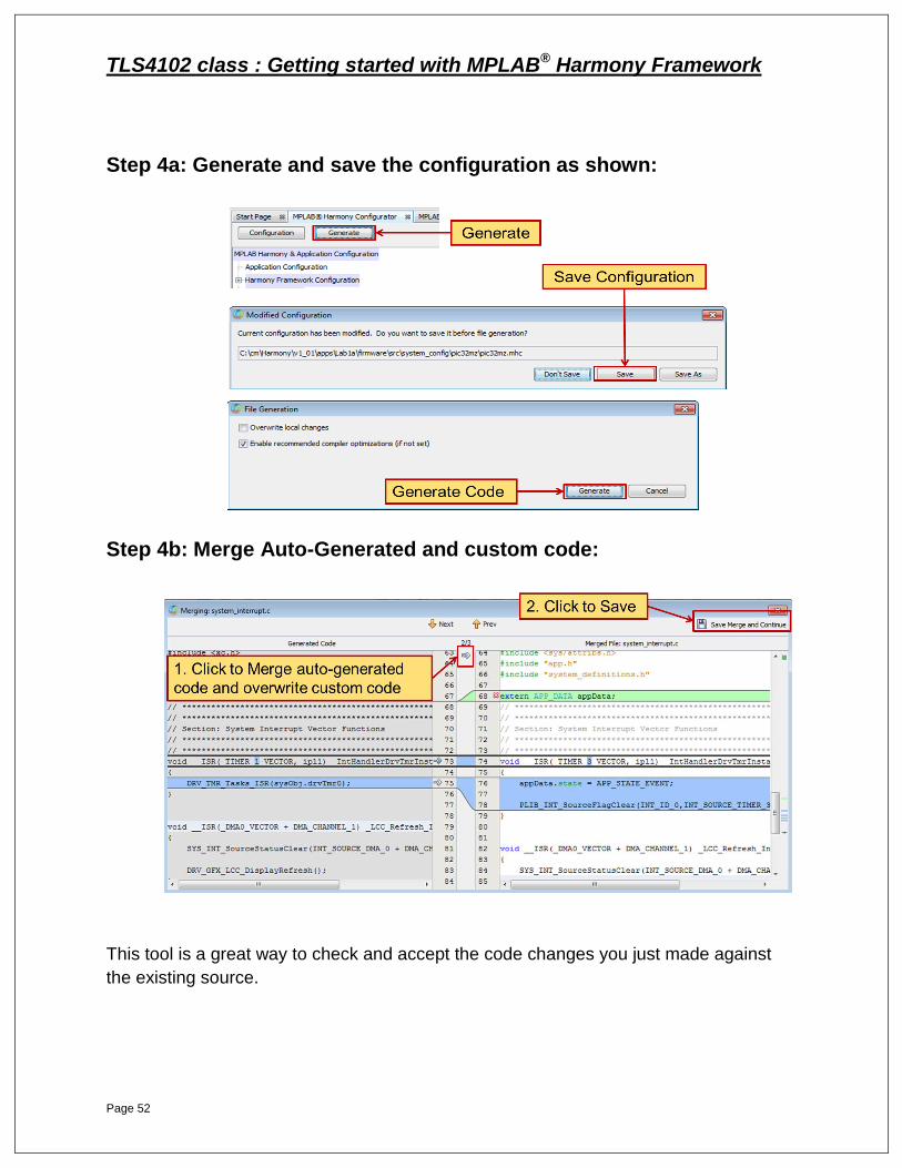
Step 4a: Generate and save the configuration as shown:
Step 4b: Merge Auto-Generated and custom code:
This tool is a great way to check and accept the code changes you just made against
the existing source.
TLS4102 class : Getting started with MPLAB® Harmony Framework
Page 53
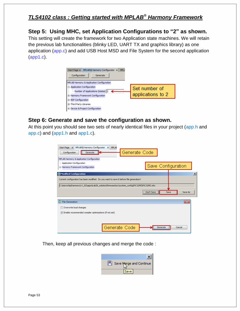
Step 5: Using MHC, set Application Configurations to “2” as shown.
This setting will create the framework for two Application state machines. We will retain
the previous lab functionalities (blinky LED, UART TX and graphics library) as one
application (app.c) and add USB Host MSD and File System for the second application
(app1.c).
Step 6: Generate and save the configuration as shown.
At this point you should see two sets of nearly identical files in your project (app.h and
app.c) and (app1.h and app1.c).
Then, keep all previous changes and merge the code :
TLS4102 class : Getting started with MPLAB® Harmony Framework
Page 54
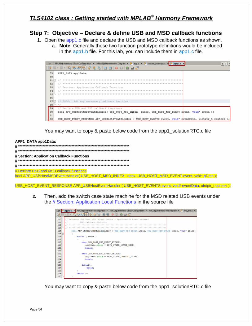
Step 7: Objective – Declare & define USB and MSD callback functions
1. Open the app1.c file and declare the USB and MSD callback functions as shown. a. Note: Generally these two function prototype definitions would be included
in the app1.h file. For this lab, you can include them in app1.c file.
You may want to copy & paste below code from the app1_solutionRTC.c file
APP1_DATA app1Data;
// *****************************************************************************
// *****************************************************************************
// Section: Application Callback Functions
// *****************************************************************************
// *****************************************************************************
// Declare USB and MSD callback functions
bool APP_USBHostMSDEventHandler( USB_HOST_MSD_INDEX index, USB_HOST_MSD_EVENT event, void* pData );
USB_HOST_EVENT_RESPONSE APP_USBHostEventHandler ( USB_HOST_EVENTS event, void* eventData, uintptr_t context );
2. Then, add the switch case state machine for the MSD related USB events under the // Section: Application Local Functions in the source file
You may want to copy & paste below code from the app1_solutionRTC.c file
TLS4102 class : Getting started with MPLAB® Harmony Framework
Page 55
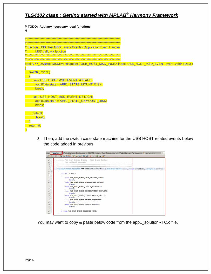
/* TODO: Add any necessary local functions.
*/
// *****************************************************************************
// *****************************************************************************
// Section: USB Host MSD Layers Events - Application Event Handler
// MSD callback function
// *****************************************************************************
// *****************************************************************************
bool APP_USBHostMSDEventHandler ( USB_HOST_MSD_INDEX index, USB_HOST_MSD_EVENT event, void* pData )
{
switch ( event )
{
case USB_HOST_MSD_EVENT_ATTACH:
app1Data.state = APP1_STATE_MOUNT_DISK;
break;
case USB_HOST_MSD_EVENT_DETACH:
app1Data.state = APP1_STATE_UNMOUNT_DISK;
break;
default:
break;
}
return 0;
}
3. Then, add the switch case state machine for the USB HOST related events below
the code added in previous :
You may want to copy & paste below code from the app1_solutionRTC.c file.
TLS4102 class : Getting started with MPLAB® Harmony Framework
Page 56
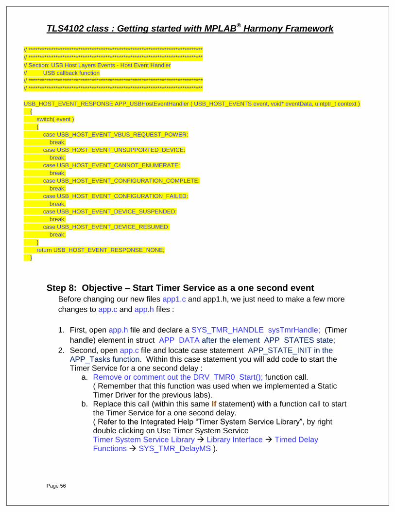
// *****************************************************************************
// *****************************************************************************
// Section: USB Host Layers Events - Host Event Handler
// USB callback function
// *****************************************************************************
// *****************************************************************************
USB_HOST_EVENT_RESPONSE APP_USBHostEventHandler ( USB_HOST_EVENTS event, void* eventData, uintptr_t context )
{
switch( event )
{
case USB_HOST_EVENT_VBUS_REQUEST_POWER:
break;
case USB_HOST_EVENT_UNSUPPORTED_DEVICE:
break;
case USB_HOST_EVENT_CANNOT_ENUMERATE:
break;
case USB_HOST_EVENT_CONFIGURATION_COMPLETE:
break;
case USB_HOST_EVENT_CONFIGURATION_FAILED:
break;
case USB_HOST_EVENT_DEVICE_SUSPENDED:
break;
case USB_HOST_EVENT_DEVICE_RESUMED:
break;
}
return USB_HOST_EVENT_RESPONSE_NONE;
}
Step 8: Objective – Start Timer Service as a one second event
Before changing our new files app1.c and app1.h, we just need to make a few more
changes to app.c and app.h files :
1. First, open app.h file and declare a SYS_TMR_HANDLE sysTmrHandle; (Timer
handle) element in struct APP_DATA after the element APP_STATES state;
2. Second, open app.c file and locate case statement APP_STATE_INIT in the APP_Tasks function. Within this case statement you will add code to start the Timer Service for a one second delay :
a. Remove or comment out the DRV_TMR0_Start(); function call. ( Remember that this function was used when we implemented a Static Timer Driver for the previous labs).
b. Replace this call (within this same If statement) with a function call to start the Timer Service for a one second delay. ( Refer to the Integrated Help “Timer System Service Library”, by right double clicking on Use Timer System Service Timer System Service Library Library Interface Timed Delay Functions SYS_TMR_DelayMS ).
TLS4102 class : Getting started with MPLAB® Harmony Framework
Page 57
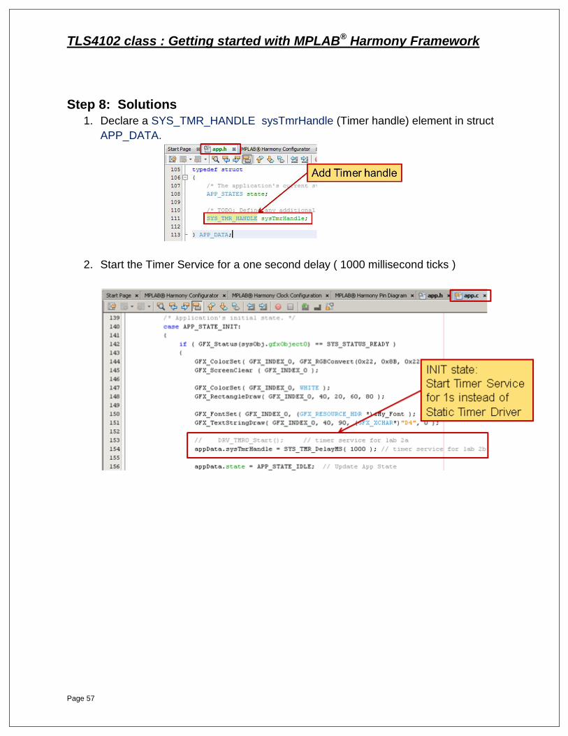
Step 8: Solutions
1. Declare a SYS_TMR_HANDLE sysTmrHandle (Timer handle) element in struct
APP_DATA.
2. Start the Timer Service for a one second delay ( 1000 millisecond ticks )

TLS4102 class : Getting started with MPLAB® Harmony Framework
Page 58
Step 9: Objective – Use Timer Service as 1 second event
1. Open app.c file and locate case statement APP_STATE_IDLE. Within this case statement add code to do the following:
a. Test If Timer Service has expired using SYS_TMR_DelayStatusGet(arg). If test is TRUE, then:
i. Update appData.state to APP_STATE_EVENT Hint: Remember that you defined this state in app.h file
ii. Restart the Timer Service for one second delay
=============================================================
Step 9: Solution
1. Add If statement and test for Timer Service expiration.
a. If test is TRUE, update application state and restart Timer Service for one
second delay.
You may want to copy & paste below code from the app_solutionRTC.c file.
if ( SYS_TMR_DelayStatusGet( appData.sysTmrHandle) )
{
/* 1000ms delay is complete. We can now toggle LED */
appData.state = APP_STATE_EVENT;
appData.sysTmrHandle = SYS_TMR_DelayMS( 1000 );
}
TLS4102 class : Getting started with MPLAB® Harmony Framework
Page 59
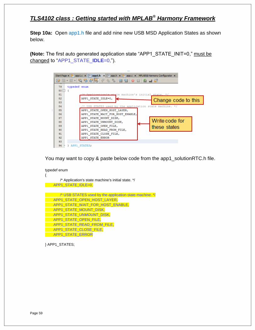
Step 10a: Open app1.h file and add nine new USB MSD Application States as shown
below.
(Note: The first auto generated application state “APP1_STATE_INIT=0,” must be
changed to “APP1_STATE_IDLE=0,”).
You may want to copy & paste below code from the app1_solutionRTC.h file.
typedef enum
{
/* Application's state machine's initial state. */
APP1_STATE_IDLE=0,
/* USB STATES used by the application state machine. */
APP1_STATE_OPEN_HOST_LAYER,
APP1_STATE_WAIT_FOR_HOST_ENABLE,
APP1_STATE_MOUNT_DISK,
APP1_STATE_UNMOUNT_DISK,
APP1_STATE_OPEN_FILE,
APP1_STATE_READ_FROM_FILE,
APP1_STATE_CLOSE_FILE,
APP1_STATE_ERROR
} APP1_STATES;
TLS4102 class : Getting started with MPLAB® Harmony Framework
Page 60
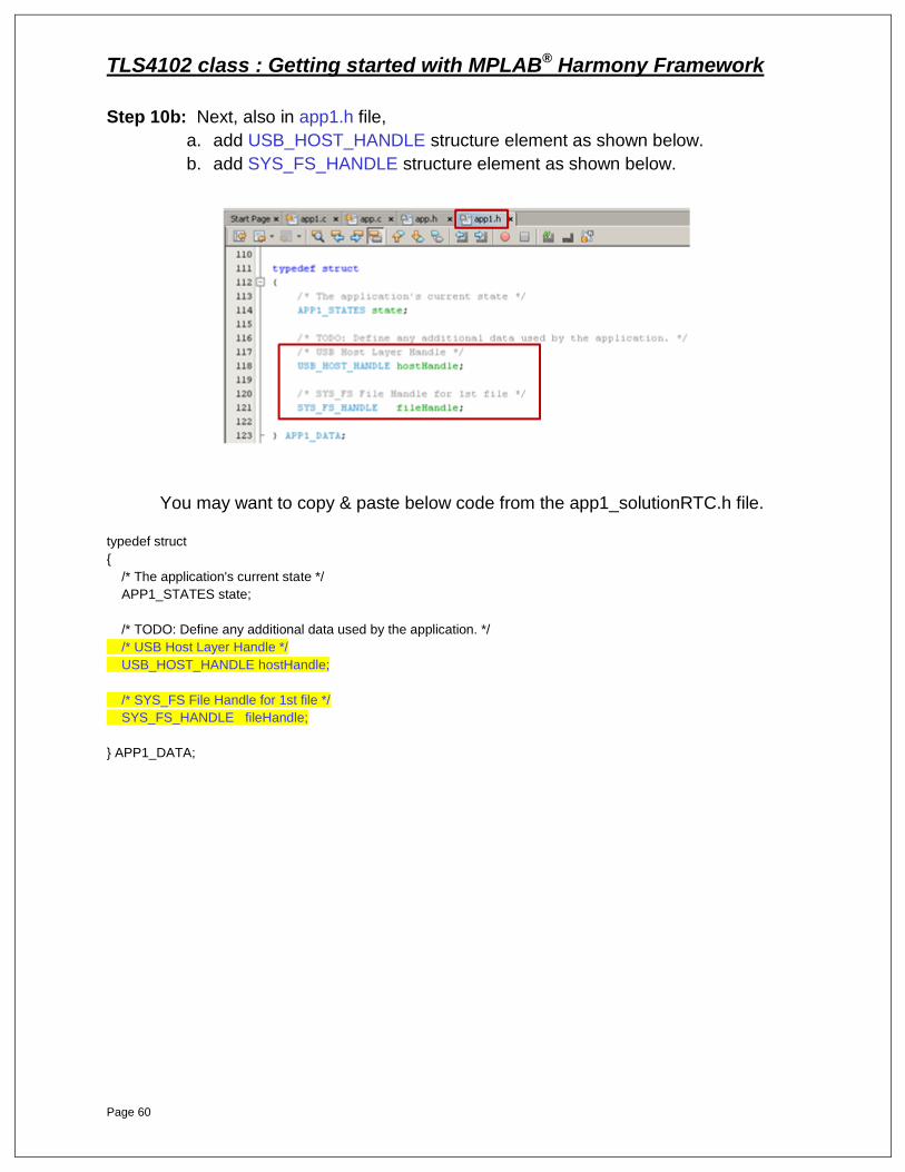
Step 10b: Next, also in app1.h file,
a. add USB_HOST_HANDLE structure element as shown below.
b. add SYS_FS_HANDLE structure element as shown below.
You may want to copy & paste below code from the app1_solutionRTC.h file.
typedef struct
{
/* The application's current state */
APP1_STATES state;
/* TODO: Define any additional data used by the application. */
/* USB Host Layer Handle */
USB_HOST_HANDLE hostHandle;
/* SYS_FS File Handle for 1st file */
SYS_FS_HANDLE fileHandle;
} APP1_DATA;

TLS4102 class : Getting started with MPLAB® Harmony Framework
Page 61
Note: Step 11 has many code development requirements. Please refer to the
solution file (app1_solution.c) if you elect to copy and paste some or all of the code
(lots of changes are needed).
Step 11a: Open app1.c file and in the void APP1_Initialize (void) function change
app1Data.state default state APP1_STATE_INIT to APP1_STATE_IDLE
Step 11b: continue with app1.c file. First, we need to remove the existing
APP1_STATE_INIT state from the (void) APP1_Tasks (void) function :
Step 11c: continue with app1.c file. and add a new USB MSD Application State in the
existing APP1_Tasks () function :
STATE: APP1_STATE_OPEN_HOST_LAYER
TLS4102 class : Getting started with MPLAB® Harmony Framework
Page 62
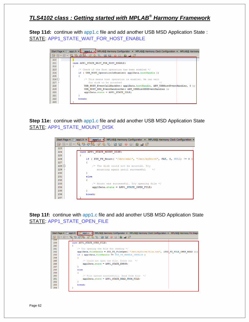
Step 11d: continue with app1.c file and add another USB MSD Application State :
STATE: APP1_STATE_WAIT_FOR_HOST_ENABLE
Step 11e: continue with app1.c file and add another USB MSD Application State
STATE: APP1_STATE_MOUNT_DISK
Step 11f: continue with app1.c file and add another USB MSD Application State
STATE: APP1_STATE_OPEN_FILE

TLS4102 class : Getting started with MPLAB® Harmony Framework
Page 63
Step 11g: continue with app1.c file and add another USB MSD Application State
STATE: APP1_STATE_READ_FROM_FILE
Step 11h: continue with app1.c file and add another USB MSD Application State
STATE: APP1_STATE_CLOSE_FILE and APP1_STATE_IDLE

TLS4102 class : Getting started with MPLAB® Harmony Framework
Page 64
Step 11i: continue with app1.c file and add another USB MSD Application State
STATE: APP1_STATE_UNMOUNT_DISK
Step 11j: continue with app1.c file and add another USB MSD Application State
STATE: APP1_STATE_ERROR
TLS4102 class : Getting started with MPLAB® Harmony Framework
Page 65
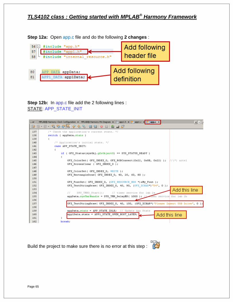
Step 12a: Open app.c file and do the following 2 changes :
Step 12b: In app.c file add the 2 following lines :
STATE: APP_STATE_INIT
Build the project to make sure there is no error at this step :
TLS4102 class : Getting started with MPLAB® Harmony Framework
Page 66
Step 13:
1. Connect the USB Pen Drive to your PC.
2. Copy the “file.txt” from the Lab2b directory to the USB pen drive root level.
The file.txt contains the 12 characters string MPLABHarmony .
If you want to change this string, make sure it is exactly the same length (12
characters)
You can now build, program, and run the application by pressing
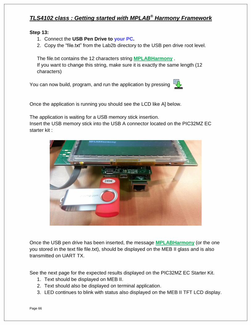
Once the application is running you should see the LCD like A] below.
The application is waiting for a USB memory stick insertion.
Insert the USB memory stick into the USB A connector located on the PIC32MZ EC
starter kit :
Once the USB pen drive has been inserted, the message MPLABHarmony (or the one
you stored in the text file file.txt), should be displayed on the MEB II glass and is also
transmitted on UART TX.
See the next page for the expected results displayed on the PIC32MZ EC Starter Kit.
1. Text should be displayed on MEB II.
2. Text should also be displayed on terminal application.
3. LED continues to blink with status also displayed on the MEB II TFT LCD display.
TLS4102 class : Getting started with MPLAB® Harmony Framework
Page 67
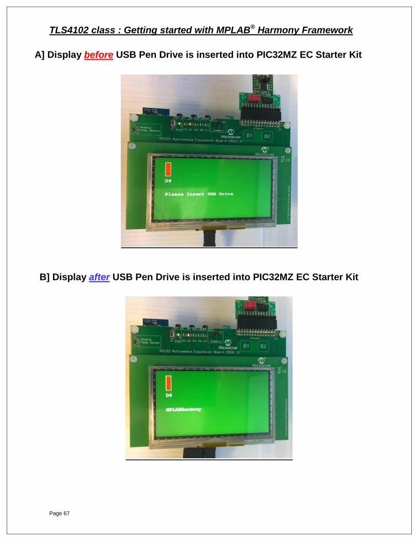
A] Display before USB Pen Drive is inserted into PIC32MZ EC Starter Kit
B] Display after USB Pen Drive is inserted into PIC32MZ EC Starter Kit
TLS4102 class : Getting started with MPLAB® Harmony Framework
Page 68
LAB 3: Migration in
MPLAB® Harmony

TLS4102 class : Getting started with MPLAB® Harmony Framework
Page 69
LAB 3: Migration in MPLAB® Harmony
Purpose: After completing Lab 3, you will gain a better understanding on how to use the MPLAB
X IDE and MHC to seamlessly migrate your application across the PIC32 MCU product
families.
Procedure: It is unlikely you will have both hardware platforms required for this lab. It is still useful
for you to experience the steps required to migrate a design from one hardware platform
to another.
For Lab 3, no code development is required. We will take the resultant Lab 2b solution,
running on the PIC32MZ MCU and its respective hardware, and seamlessly migrate to
the PIC32MX MCU and its respective hardware. This is basically a two-part process.
All nine steps must be completed before you will be ready to build, download and
run the application. Here are the steps you will work through:
Part 1: Create New Configuration
Step 1 – Create a new MPLAB X Configuration
Step 2 – Choose Device and Tools Step 3 – Set new “PIC32MX” configuration as active
Part 2: Configure PIC32MX and Harmony Components
Step 4 – With MHC, Configure PIC32MX BSP
Step 5 – With MHC, Configure PIC32MX Clocks
Step 6a – With MHC, Configure PIC32MX UART Driver
Step 6b – With MHC, Configure PIC32MX PMP Driver
Step 7 – With MHC, Configure Graphics Library
Step 8 – With MHC, Configure USB Host MSD Library
Step 9 – With MHC, Generate and Save code
PIC32MZ with MEB II PIC32MX with MEB I
TLS4102 class : Getting started with MPLAB® Harmony Framework
Page 70
TLS4102 class : Getting started with MPLAB® Harmony Framework
Page 71
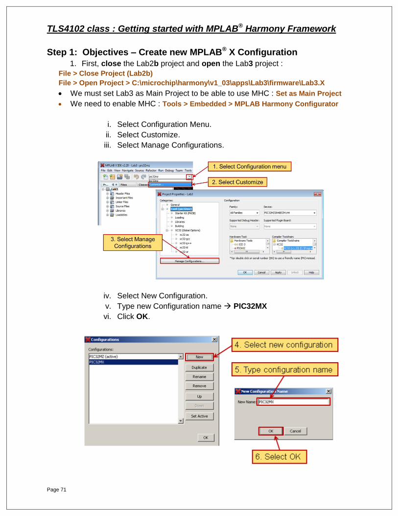
Step 1: Objectives – Create new MPLAB® X Configuration
1. First, close the Lab2b project and open the Lab3 project :
File > Close Project (Lab2b)
File > Open Project > C:\microchip\harmony\v1_03\apps\Lab3\firmware\Lab3.X
We must set Lab3 as Main Project to be able to use MHC : Set as Main Project
We need to enable MHC : Tools > Embedded > MPLAB Harmony Configurator
i. Select Configuration Menu.
ii. Select Customize.
iii. Select Manage Configurations.
iv. Select New Configuration.
v. Type new Configuration name PIC32MX
vi. Click OK.
TLS4102 class : Getting started with MPLAB® Harmony Framework
Page 72
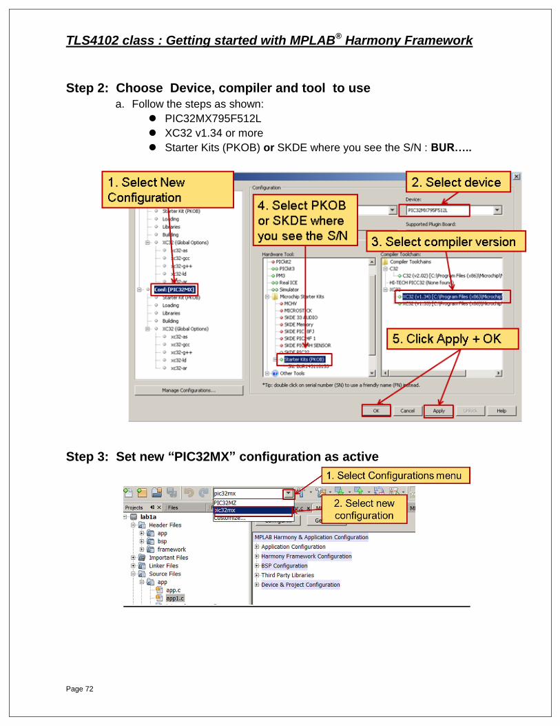
Step 2: Choose Device, compiler and tool to use
a. Follow the steps as shown:
PIC32MX795F512L
XC32 v1.34 or more
Starter Kits (PKOB) or SKDE where you see the S/N : BUR…..
Step 3: Set new “PIC32MX” configuration as active
TLS4102 class : Getting started with MPLAB® Harmony Framework
Page 73
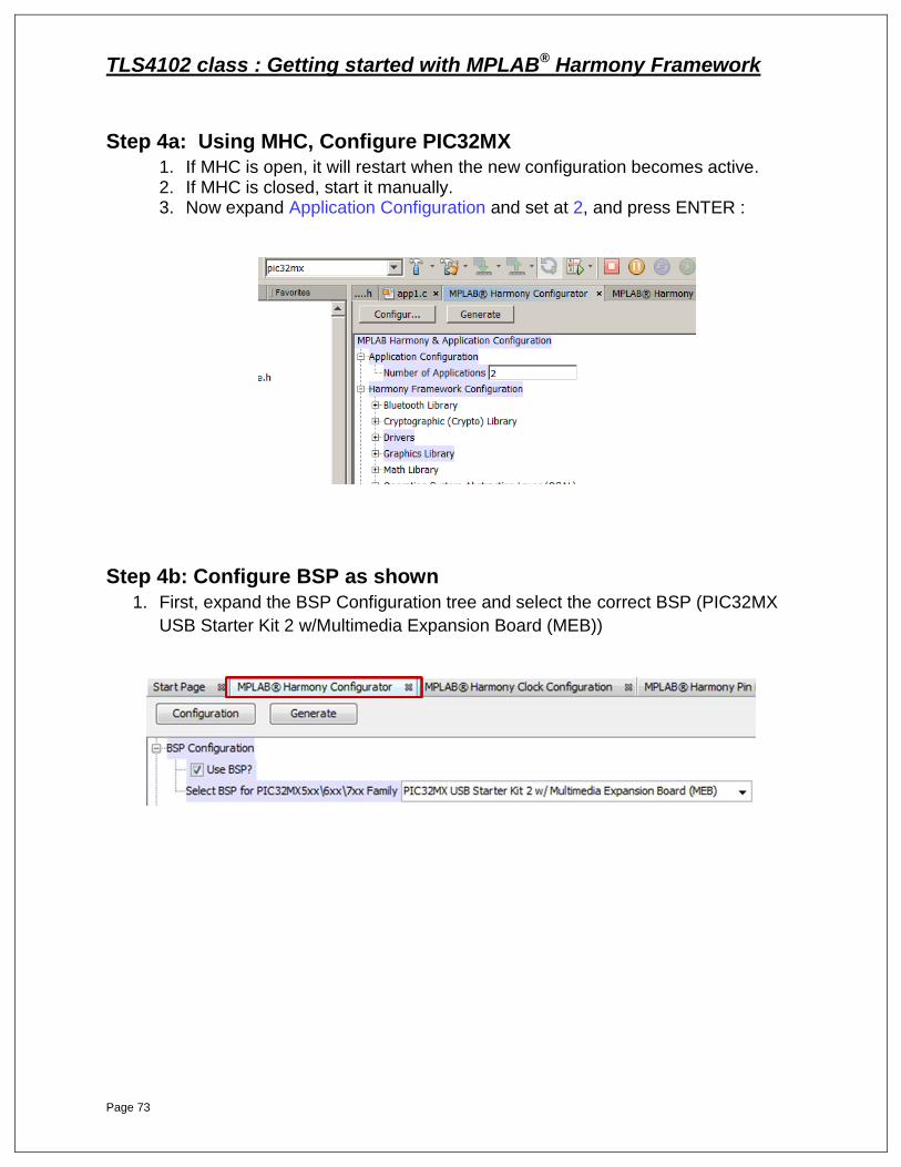
Step 4a: Using MHC, Configure PIC32MX
1. If MHC is open, it will restart when the new configuration becomes active. 2. If MHC is closed, start it manually. 3. Now expand Application Configuration and set at 2, and press ENTER :
Step 4b: Configure BSP as shown
1. First, expand the BSP Configuration tree and select the correct BSP (PIC32MX
USB Starter Kit 2 w/Multimedia Expansion Board (MEB))
TLS4102 class : Getting started with MPLAB® Harmony Framework
Page 74
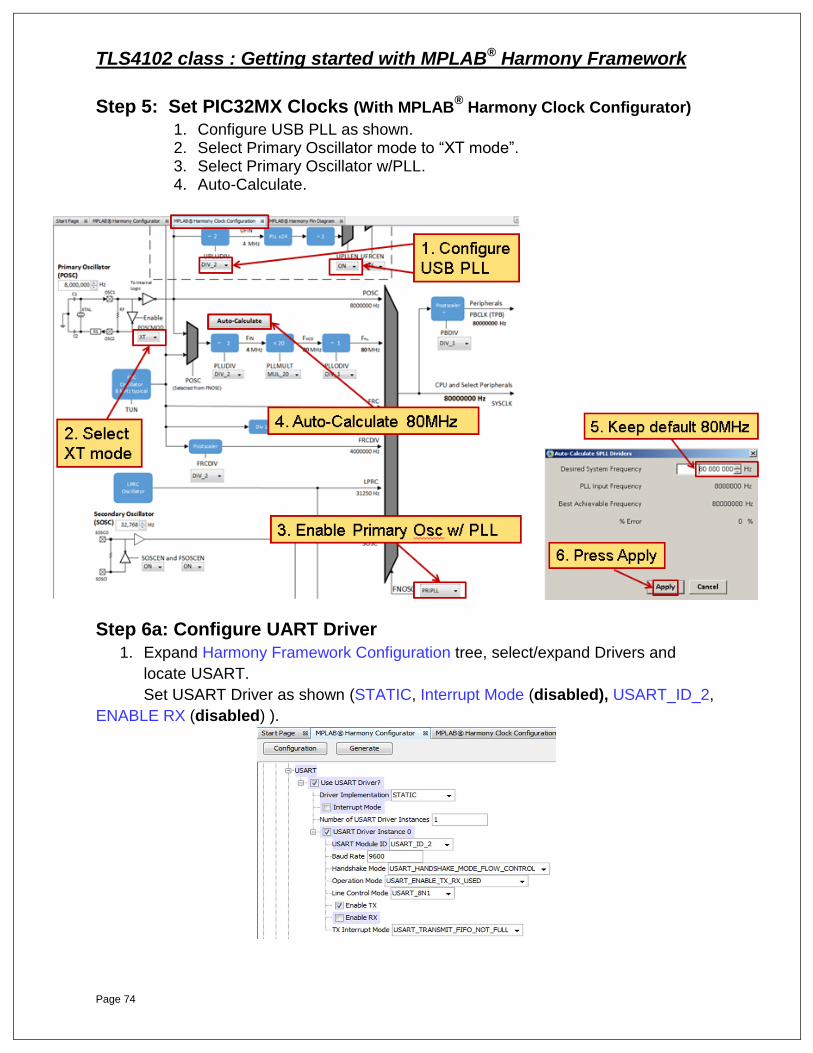
Step 5: Set PIC32MX Clocks (With MPLAB® Harmony Clock Configurator)
1. Configure USB PLL as shown. 2. Select Primary Oscillator mode to “XT mode”. 3. Select Primary Oscillator w/PLL. 4. Auto-Calculate.
Step 6a: Configure UART Driver
1. Expand Harmony Framework Configuration tree, select/expand Drivers and
locate USART.
Set USART Driver as shown (STATIC, Interrupt Mode (disabled), USART_ID_2,
ENABLE RX (disabled) ).

TLS4102 class : Getting started with MPLAB® Harmony Framework
Page 75
Step 6b: Configure PMP Driver
1. Expand Harmony Framework Configuration tree, select/expand Drivers and
locate PMP.
Set PMP Driver as shown :
Driver implementation : STATIC,
Strobe Wait states : PMP_STROBE_WAIT_5
Select Read Strobe Enable with Polariy PMP_POLARITY_ACTIVE_LOW
Select Write Strobe Enable with Polarity PMP_POLARITY_ACTIVE_LOW

TLS4102 class : Getting started with MPLAB® Harmony Framework
Page 76
Step 7: Expand Harmony Framework Configuration tree,
select/expand Graphics Library and configure Graphics Library as
shown.
Step 8: Select and Enable USB Host MSD Library
TLS4102 class : Getting started with MPLAB® Harmony Framework
Page 77
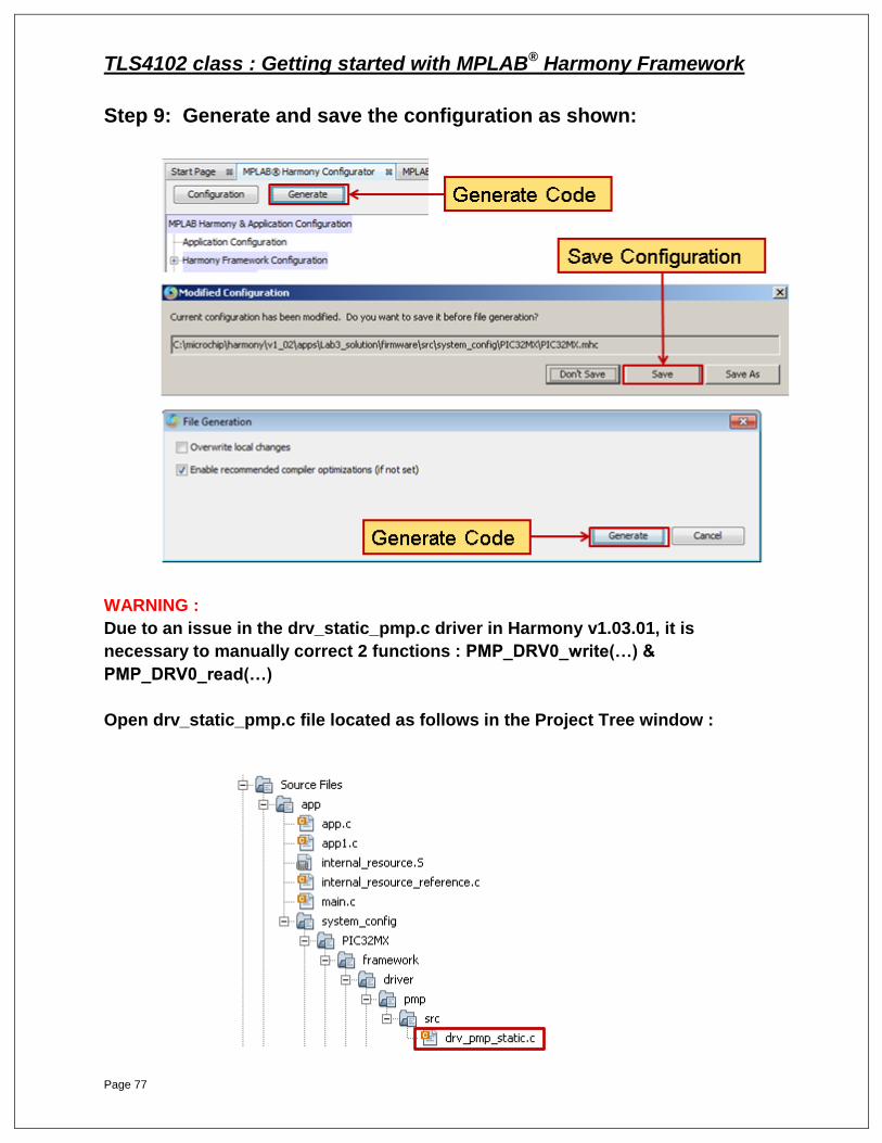
Step 9: Generate and save the configuration as shown:
WARNING :
Due to an issue in the drv_static_pmp.c driver in Harmony v1.03.01, it is
necessary to manually correct 2 functions : PMP_DRV0_write(…) &
PMP_DRV0_read(…)
Open drv_static_pmp.c file located as follows in the Project Tree window :
TLS4102 class : Getting started with MPLAB® Harmony Framework
Page 78
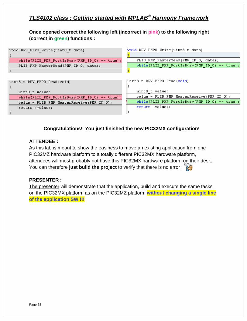
Once opened correct the following left (incorrect in pink) to the following right
(correct in green) functions :
Congratulations! You just finished the new PIC32MX configuration!
ATTENDEE :
As this lab is meant to show the easiness to move an existing application from one
PIC32MZ hardware platform to a totally different PIC32MX hardware platform,
attendees will most probably not have this PIC32MX hardware platform on their desk.
You can therefore just build the project to verify that there is no error :
PRESENTER :
The presenter will demonstrate that the application, build and execute the same tasks
on the PIC32MX platform as on the PIC32MZ platform without changing a single line
of the application SW !!!
TLS4102 class : Getting started with MPLAB® Harmony Framework
Page 79
PIC32MX platform setup
For the MEB hardware platform based on PIC32MX, ensure that the jumpers on
the UART-to-USB Pictail adaptor board have been relocated to the MEB1
position.
You can now build, program, and run the application :
When the final application is running and you insert a USB Pen Drive into the
PIC32MX Starter Kit a stored message is read out from the Pen Drive and
displayed on the MEB TFT display (which even has a different size !) and also
transmitted on UART TX. (Pay attention that the COM Port has most probably
changed).
See the next page for expected results displayed on the PIC32MX hardware.
1. Text should be displayed on the MEB display.
2. Text should also be displayed on terminal application.
3. LED continues to blink with status also displayed on the MEB TFT LCD
display.
TLS4102 class : Getting started with MPLAB® Harmony Framework
Page 80
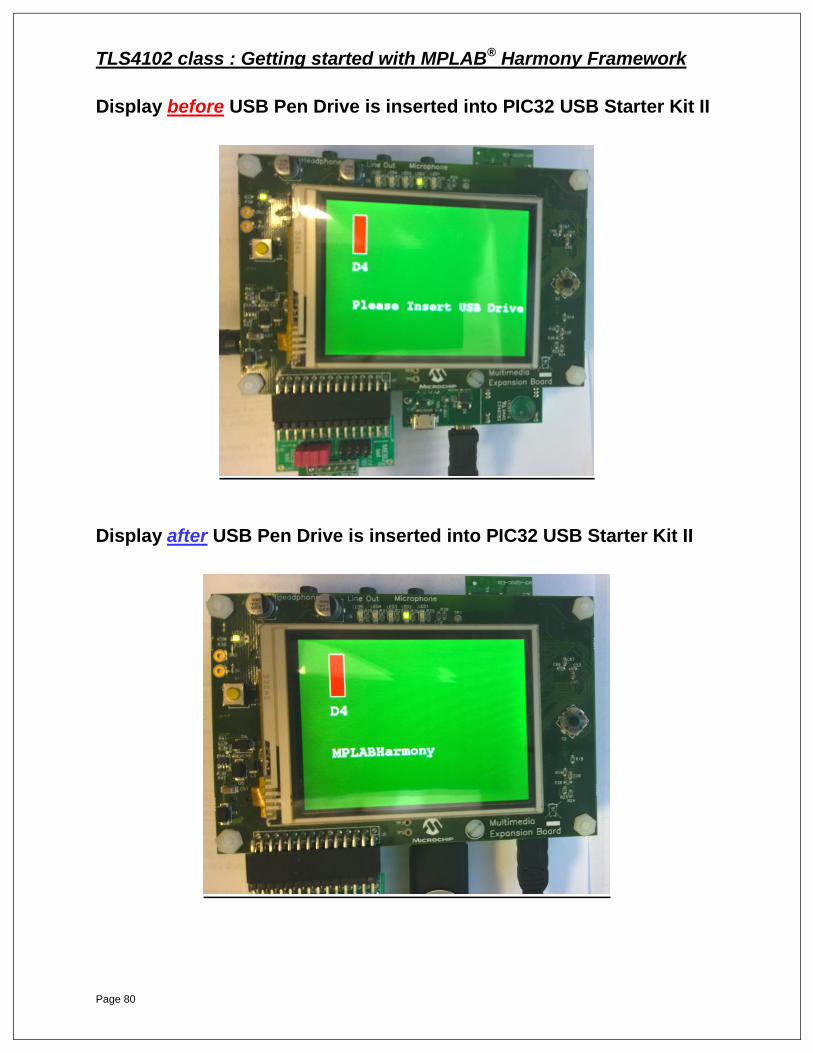
Display before USB Pen Drive is inserted into PIC32 USB Starter Kit II
Display after USB Pen Drive is inserted into PIC32 USB Starter Kit II

TLS4102 class : Getting started with MPLAB® Harmony Framework
Page 81
Lab 4 Demo: MPLAB®
Harmony and RTOSes
TLS4102 class : Getting started with MPLAB® Harmony Framework
Page 82
Lab 4 Demo: MPLAB® Harmony and RTOSes
Demo Objectives:
Overview on how MPLAB Harmony and RTOSes work together in an
application
Gain a brief understanding of how MPLAB Harmony drivers and
middleware operate in a multi-threaded pre-emptive environment
Brief overview of the term Operating System Abstraction Layer
(OSAL).
UART Driver Demo
Two tasks try to access the same hardware UART peripheral to print
out an ASCII string. Each tasks prints its own unique string
Each task will run and try to print its own unique string, when its
associated pushbutton switch is .pressed.
By connecting a USB cable from the starter kit to a PC, and opening
an ASCII terminal emulator program (TeraTerm Pro, RealTerm, etc.),
the user can see the ASCII strings being correctly printed.
USB Stack Demo
This demo is a take home but the concept is the same as the UART
driver demo, just with a more complex piece of software. This demo
shows the complexity of running multiple threads and using the
MPLAB Harmony USB stack in a thread safe manner.
TLS4102 class : Getting started with MPLAB® Harmony Framework
Page 83
Development Boards
TLS4102 class : Getting started with MPLAB® Harmony Framework
Page 84
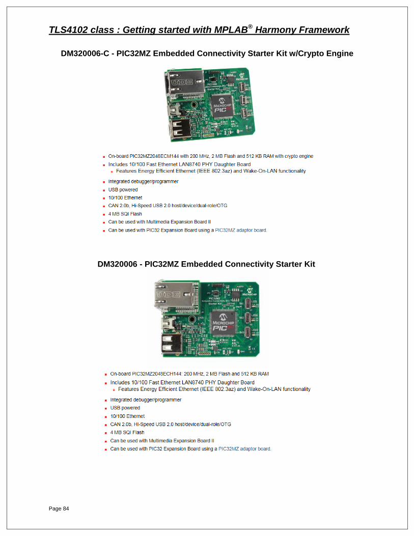
DM320006-C - PIC32MZ Embedded Connectivity Starter Kit w/Crypto Engine
DM320006 - PIC32MZ Embedded Connectivity Starter Kit
TLS4102 class : Getting started with MPLAB® Harmony Framework
Page 85
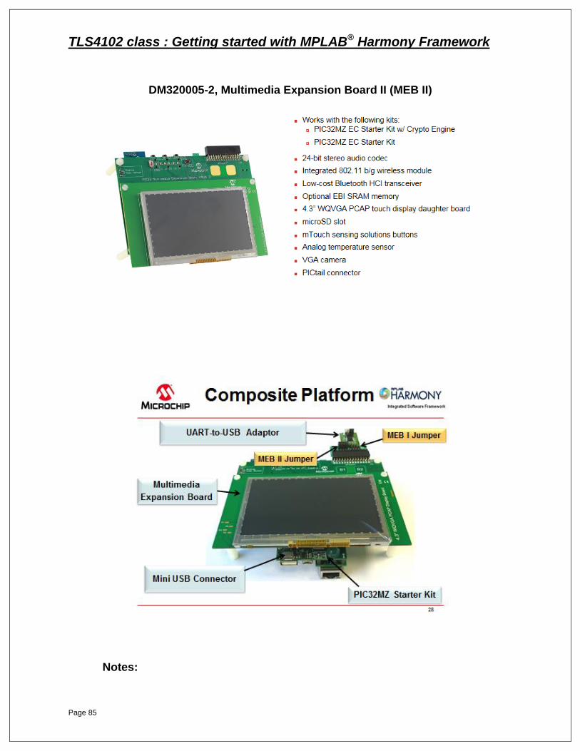
DM320005-2, Multimedia Expansion Board II (MEB II)
Notes:


![Dhcp lab [ttg training center]](https://img.dokumen.tips/doc/110x75/5582418bd8b42a213a8b4579/dhcp-lab-ttg-training-center.jpg)