Embed Size (px)
Citation preview


For this prototype we have chosen a NI-PCI-6503 acquisition board from National Instruments [6]. This is an acquisition card with 24 digital input/output lines organized in three 8 bit ports, and PCI connection to the computer. The board is in the basic range for this manufacturer, and its price is low compared with other solutions. For our purposes, one port is used as output and sets up the four variable values, other port is set up as input and his four lower bits reads the functions results and in the last one several bits are set up as output to put the switch values into the memory and others act as inputs for handshaking.
• A webcam.
The webcam is used to receive visual feedback from the function generator circuit. The circuit has LEDs for inputs and outputs. A view of the circuit lets the students check out the state of the variables and functions. There are no moving parts in the circuit, and the changes on the LEDs state are slow, so a rate of one frame per second is enough for our purposes. The webcam have extra illumination with LED lighting that only goes on when an experiment is running.
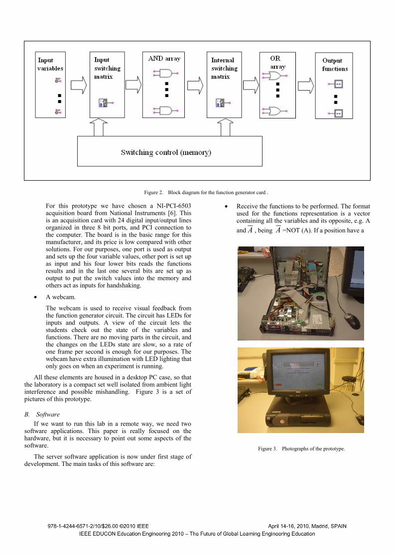
All these elements are housed in a desktop PC case, so that the laboratory is a compact set well isolated from ambient light interference and possible mishandling. Figure 3 is a set of pictures of this prototype.
B. Software If we want to run this lab in a remote way, we need two
software applications. This paper is really focused on the hardware, but it is necessary to point out some aspects of the software.
The server software application is now under first stage of development. The main tasks of this software are:
• Receive the functions to be performed. The format used for the functions representation is a vector containing all the variables and its opposite, e.g. A and A , being A =NOT (A). If a position have a
Figure 3. Photographs of the prototype.
Figure 2. Block diagram for the function generator card .
359
“1”, the variable is present, if have a “0” not. An example could be the following function:
DACBACBF ++= (1)
That can be represented as:
0001100010100100
01000010)( =DCBAABCDF (2)
• Program the switches. The software takes the vector representation, like the example shows in (2), and programs the switching matrix according to the function. Every value of an element of the vector is an input switch, and the number of elements of the vector determines how many internal switch will be closed.
• Put input values on the variables. Once the functions are programmed, the user can select one input variables combination to be sent to the function, and the software will put these values in the function generator card inputs.
• Take output values of the functions. The acquisition card reads the results from the functions implemented in the function generator card and sends to the user for verification.
• Makes the truth table. If it is desired, the software can build the truth table for the functions.
This software has been developed in Labview environment [7] [8]. This developed software kit allows an easy communication with the DAQ card, and has been used in older similar projects [4].
The software can add new features to improve the system, or even to change its functionality. For example, with a new version of software we can transform the remote laboratory in an “in situ” laboratory. With this example version, the students could build the switch matrix by themselves selecting in a schematic view of the function generator board the state of all the switches.
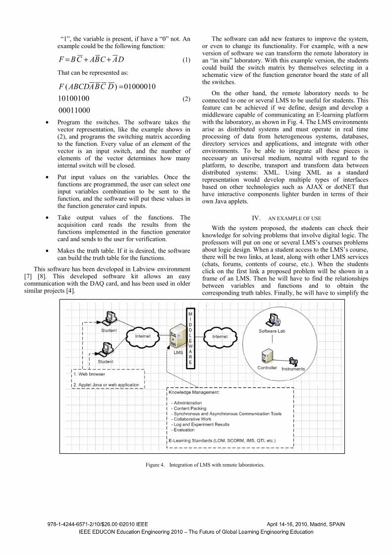
On the other hand, the remote laboratory needs to be connected to one or several LMS to be useful for students. This feature can be achieved if we define, design and develop a middleware capable of communicating an E-learning platform with the laboratory, as shown in Fig. 4. The LMS environments arise as distributed systems and must operate in real time processing of data from heterogeneous systems, databases, directory services and applications, and integrate with other environments. To be able to integrate all these pieces is necessary an universal medium, neutral with regard to the platform, to describe, transport and transform data between distributed systems: XML. Using XML as a standard representation would develop multiple types of interfaces based on other technologies such as AJAX or dotNET that have interactive components lighter burden in terms of their own Java applets.
IV. AN EXAMPLE OF USE With the system proposed, the students can check their
knowledge for solving problems that involve digital logic. The professors will put on one or several LMS’s courses problems about logic design. When a student access to the LMS’s course, there will be two links, at least, along with other LMS services (chats, forums, contents of course, etc.). When the students click on the first link a proposed problem will be shown in a frame of an LMS. Then he will have to find the relationships between variables and functions and to obtain the corresponding truth tables. Finally, he will have to simplify the
Figure 4. Integration of LMS with remote laboratories.
360
functions using any method (e.g. K-maps). Once the problem is done by the student, he goes back to the second link and the student can enter the remote laboratory through LMS`s course and intro the functions obtained. A comparison between the truth tables obtained and the ones offered by the remote laboratory will be the final result of the experiment. The log file of the sessions helps the professors to evaluate the student skills. It important to say that the students beside of working with the problem and the remote lab, he can use the services offered by LMS as chats forums, etc.
V. CONCLUSIONS A remote laboratory developed to check digital functions
has been presented. At this moment, only hardware is on an advanced step, therefore not been possible to obtain results of its application in a group of students.
The main features of this approach are:
• It’s a laboratory designed for use inside any LMS.
• It’s a low cost, low power consumption system.
• Simplify the implementation of truth tables.
• It’s very versatile.
• It can be used “in situ” only with a new software development.
• It’s open to future developments.
VI. ACKNOWLEDGMENTS This work has been developed inside the framework of the
S-Labs (”Open services integration for distributed, reusable and secure remote and virtual laboratories”) Project, supported by the Spanish National Plan for R&D (2008 – 2011) of the
Science Ministry. Our thanks to all the people involved in this Project.
The authors would like to thank the help of the students who have worked in the early stages of design, especially Fernando Ortiz Benito and Jesús María Gutiérrez Calzada, and those who have tested the system and provided critical feedback on their performance.
Also we would like to acknowledge the help of the UPM and the UNED for the publication and attendance to the conference.
REFERENCES [1] E. Sancristobal, S. Martin, R. Gil. G. Díaz, A. Colmenar, "Integration of
Internet Based Labs and Open Source LMS," ICIW, pp.217-222, 2008 Third International Conference on Internet and Web Applications and Services, 2008.
[2] B. Daku, “Individualized laboratory using Moodle”, 39 th ASEE/IEEE Frontiers in Education Conference, San Antonio (Texas) 2009.
[3] V. Kolias, I. Anagnostopoulos, E. Kayafas, “Remote laboratories over different platforms and applications fielda: A survey”, Proceedings of the 2nd International Workshop on e-learning and Virtual and Remote Laboratories, pp. 93 – 98, Postdam (Germany) 2008.
[4] L. Dávila, “Sistema para la realización de prácticas de Electrónica Digital asistida por ordenador” , Second Meeting ID+TIC, Alcalá de Henares (Spain) 2009.
[5] Via embedded boards. Available at: http://www.via.com.tw/en/products/embedded/boards/index.jsp
[6] PCI-650X Data sheet. National Instruments. Available at : http://www.ni.com/pdf/products/us/4daqsc379-384_374-376.pdf
[7] NI LabView User Manual. National Instruments. Available at: http://www.ni.com/pdf/manuals/320999e.pdf
[8] LabVIEW Function and VI Reference Manual. National Instruments. Available at: http://www.ni.com/pdf/manuals/321526b.pdf
361

362