Embed Size (px)
Citation preview

©2018 Roberto Muscedere Images ©2013 Pearson Education Inc. 1
Hardware Description Language Hardware Description Language (HDL)(HDL)
• For small circuits, manual methods are feasible
• For anything larger CAD tools are required• Reduces the risk of producing a flawed design
while allowing the designer creativity• Prototypes of integrated circuits are too
expensive and time consuming to build• Modern designer tools rely on a HDLs to
design and test a circuit in software before it is ever manufactured

©2018 Roberto Muscedere Images ©2013 Pearson Education Inc. 2
Hardware Description LanguageHardware Description Language• HDL is a computer-based language that
resembles an ordinary computer programming language (ie. C)• Meant to be self-documenting• Can be read by both humans and computers• Suitable as an exchange language between designers
• Specifically oriented to describing hardware structures and the behavior of logic circuits (relationship between inputs and outputs)
• It can represent: logic diagrams, truth tables, Boolean expressions, and complex abstractions

©2018 Roberto Muscedere Images ©2013 Pearson Education Inc. 3
Hardware Description LanguageHardware Description Language• HDLs are used in several major steps in the design flow
of an integrated circuit:• Design entry• Functional simulation or verification• Logic synthesis• Timing verification• Fault simulation
• Design entry creates an HDL-based description of the functionality that is to be implemented in hardware• Description can be in a variety of forms: Boolean logic equations,
truth tables, a netlist of interconnected gates, or an abstract behavioral model
• HDL model may also represent a partition of a larger circuit into smaller interconnected and interacting functional units (hierarchy)

©2018 Roberto Muscedere Images ©2013 Pearson Education Inc. 4
Hardware Description LanguageHardware Description Language• Logic simulation predicts the behavior of a digital
system through the use of a computer• Produces readable output (a time-ordered sequence of
input and output signal values or displays waveforms of the signals)
• Detects functional errors in a design (which can be corrected) without having to physically create and operate the circuit
• Testbench is another circuit which provides inputs to the design to produce the simulation results
• Written in HDL; must be a thorough test• Alternative approach relies on complex formal
mathematical verification

©2018 Roberto Muscedere Images ©2013 Pearson Education Inc. 5
Hardware Description LanguageHardware Description Language• Logic synthesis is the process of deriving a list of
physical components and their interconnections (netlist) from the HDL code• Does not compile into code but hardware components• Netlist is used to fabricate an integrated circuit or printed
circuit board (PCB) • Based on formal exact procedures that implement digital
circuits and addresses that part of a digital design which can be automated with computer software
• Today’s large and complex circuits are made with logic synthesis software

©2018 Roberto Muscedere Images ©2013 Pearson Education Inc. 6
Hardware Description LanguageHardware Description Language• Timing verification confirms that the fabricated,
integrated circuit will operate at a specified speed• Each logic gate has a propagation delay which ultimately
limit the speed of the circuit• This step checks each signal path to verify that it is not
compromised by propagation delay and other effects• Fault simulation compares the behavior of an
ideal circuit with the behavior of a circuit that contains process-induced flaws• Used to identify input stimuli that can be used to reveal
the difference between the faulty circuit and the fault-free circuit
• Test generation and fault simulation may occur at different steps in the design process to avoid the disaster of producing a circuit whose internals cannot be tested

©2018 Roberto Muscedere Images ©2013 Pearson Education Inc. 7
Hardware Description LanguageHardware Description Language• Two widely used HDLs:
• Verilog (VERIfy LOGic)• VHDL (Very High Speed Integrated Circuit HDL)
• Focus on Verilog as it is easier to introduce• Concepts are the same as VHDL• Modeling, verification, and synthesis
• Three different versions:• Verilog-1995 (or 95)• Verilog-2001• Verilog-2005

©2018 Roberto Muscedere Images ©2013 Pearson Education Inc. 8
VerilogVerilog• Has a number of keywords
• module, endmodule, input, output, wire, or, and, not, etc.• Cannot use keywords as names to any parts of your circuits
• Can comment text on a line by preceding it with “//”• Can comment large chunks of text by using “/*” to specify
starting and “*/” to specify the ending of the comment• Whitespace (blanks and newlines) are ignored• CaSe SeNsItIvE (module is not the same as MODULE)• Numeric values are in decimal by default
• Also supports:Binary (prefix of #'b, where # is the number of bits)Octal (prefix of #'o)Hexadecimal (prefix of #'h)
• Bits can be “x” (for don’t care) or “z” (for high impedance)

©2018 Roberto Muscedere Images ©2013 Pearson Education Inc. 9
VerVerilog ilog -- Module DeclarationModule Declaration• First line is comment• “module” starts the
description of the circuit• Ends with “endmodule”
• “Simple_Circuit” is the name of the circuit• Only A-Z,a-z,0-9,_ allowed
• “(A,B,C,D,E)” is the port list (inputs and outputs); ends with “;”
• Define direction of ports• Either “input” or “output”
// My circuitmodule Simple_Circuit(A, B, C, D, E);
output D, E;input A, B, C;wire w1;
and G1 (w1, A, B);not G2 (E, C);or G3 (D, w1, E);
endmodule

©2018 Roberto Muscedere Images ©2013 Pearson Education Inc. 10
VerVerilog ilog -- Module DeclarationModule Declaration• Declare internal
connections (eg. wires)• Need wires to connect
primitives (gates) or other modules
• Primitives and their connections
1. Primitive name• or, and, not, etc
2. Optional instance name3. In brackets, a list of
ports/wires to connect• Order is output, then input
• “Gate level modeling”
// My circuitmodule Simple_Circuit(A, B, C, D, E);
output D, E;input A, B, C;wire w1;
and G1 (w1, A, B);not G2 (E, C);or G3 (D, w1, E);
endmodule
©2018 Roberto Muscedere Images ©2013 Pearson Education Inc. 11
VerVerilog ilog -- Declaration and InstantiationDeclaration and Instantiation• A Verilog module is declared which specifies the input-
output behavior of the hardware that it represents• Predefined primitives are not declared because their
definition is specified by the language and is not subject to change by the user• Primitives are used (instantiated), just as gates are used to populate
a circuit• Once a module has been declared, it may be used
(instantiated) within a design• A Verilog model is a descriptive model
• Simple_Circuit describes what primitives form the circuit and how they are connected
• The behavior of the circuit is implicitly specified by the description because the behavior of each logic gate is defined• It can be used to simulate the circuit that it represents
©2018 Roberto Muscedere Images ©2013 Pearson Education Inc. 12
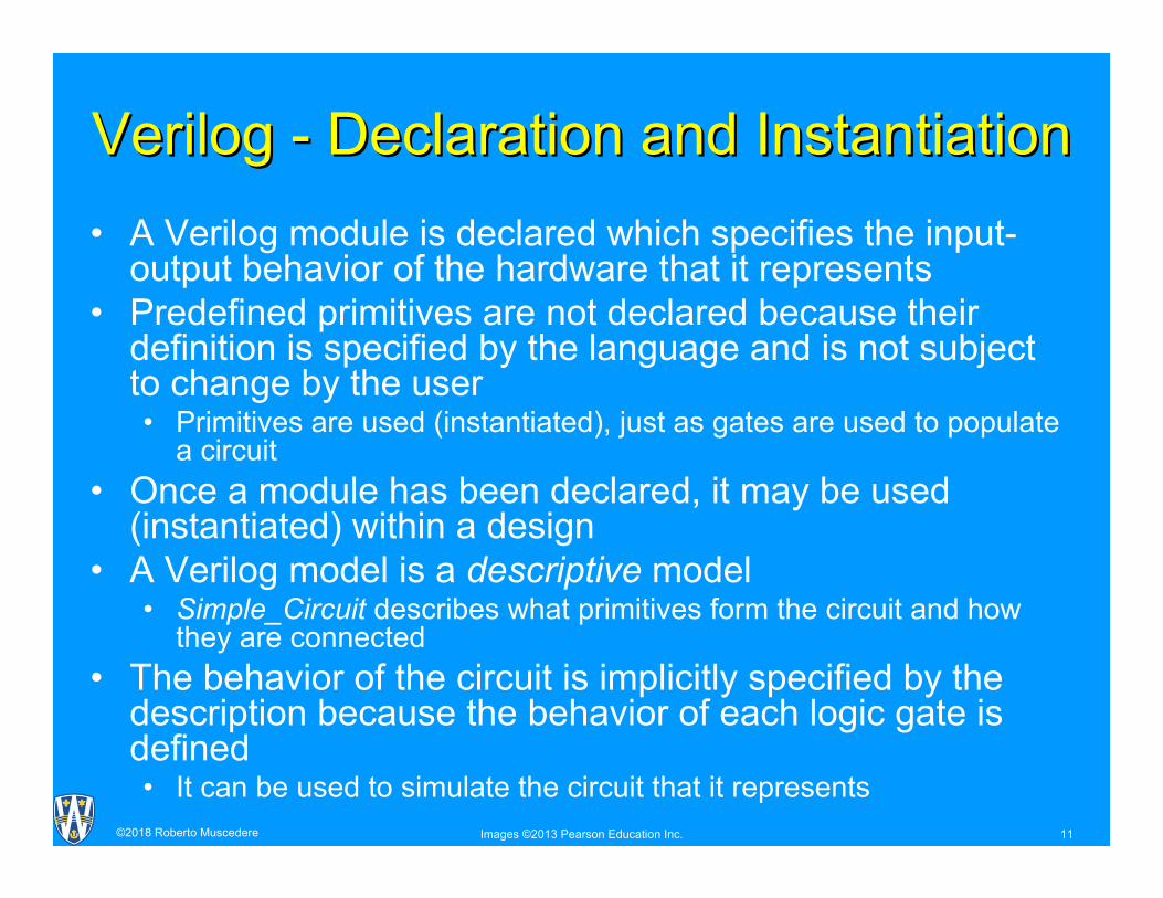
Some Some VerilogVerilog OperatorsOperators
Conditional?:Concatenation{}Lesser than<Greater than>Equality==
Logical NOT!Bitwise Not~Bitwise XOR^
Logical OR||Bitwise OR|Logical AND&&Bitwise AND&
Binary Subtraction-Binary addition+
OperationSymbolOperationSymbol

©2018 Roberto Muscedere Images ©2013 Pearson Education Inc. 13
VerVerilog ilog -- ThreeThree--State GatesState Gates• Special primitives:
• Gatename(out,in,control)• bufif1:
• Buffer if cont=1
• bufif0:• Buffer if cont=0
• notif1:• Invert if cont=1
• notif0:• Invert if cont=0
• “tri” wire type allows multiple drivers
module mux_2x1_tri_gates(Y, I0, I1, Select);
output Y;input I0, I1, Select;tri Y;
bufif0 G1 (Y, I0, Select);bufif1 G2 (Y, I1, Select);
endmodule

©2018 Roberto Muscedere Images ©2013 Pearson Education Inc. 14
VerilogVerilog -- Boolean ExpressionsBoolean Expressions• Use “assign” to apply a
boolean expression• Bitwise operators (apply to
corresponding bits):• Eg. ~1001 = 0110
• Logical operators (apply only to one bit):• Eg. !1001 = 0
• Bitwise (one bit) and logical operators are equivalent
• Precedence is questionable, use brackets whenever possible
// My boolean circuitmodule Boolean_Circuit(A, B, C, D, E);
output D, E;input A, B, C;
assign E = ~C;assign D = (A&B)|E;
endmodule

©2018 Roberto Muscedere Images ©2013 Pearson Education Inc. 15
VerilogVerilog -- Boolean ExpressionsBoolean Expressions
• Use of logical operators, in this case, would yield identical results since A, B, C, D, and F are only 1 bit
• “Data flow modeling”
module Example_Circuit(A, B, C, D, F);
output F;input A, B, C, D;
assign F =((~B)&(~D)) |((~B)&(~C)) |((~C)&(~A)&D);
endmodule

©2018 Roberto Muscedere Images ©2013 Pearson Education Inc. 16
Gate Delays and Gate Delays and UDPsUDPs
• Book discusses gates delays and User Defined Primitives (UDPs)• Neither of these are synthesisable and should be
avoided• Can be used only in simulation• Will cover a portion of “Gate Delays” later• UDPs are only useful in gate modeling

©2018 Roberto Muscedere Images ©2013 Pearson Education Inc. 17
VerilogVerilog• Verilog can use multi-bit signals:
wire [0:3] D;wire [7:0] SUM;
• D is a 4 bit signal where D[0] is the MSB and D[3] is the LSB
• SUM is an 8 bit signal where SUM[7] is the MSB and SUM[0] is the LSB
• Can access individual bits and connect then together
wire [3:0] E, G; wire F;assign E = {D[3],D[2],D[1],D[0]};assign {F,G} = {E,D[2]};
• F is D[3] and G is D[2],D[1],D[0],D[2]

©2018 Roberto Muscedere Images ©2013 Pearson Education Inc. 18
Gate Modeled 2Gate Modeled 2--4 Decoder4 Decodermodule decoder_2x4_gates(D, A, B, E);output [0: 3] D;input A, B;input E;wire An,Bn,En;not
G1 (An,A),G2 (Bn,B),G3 (En,E);
nandG4 (D[0],An,Bn,En),G5 (D[1],An,B,En),G6 (D[2],A,Bn,En),G7 (D[3],A,B,En);
endmodule

©2018 Roberto Muscedere Images ©2013 Pearson Education Inc. 19
Data Flow Modeled 2Data Flow Modeled 2--4 Decoder4 Decodermodule decoder_2x4_df(D, A, B, E);output [0: 3] D;input A, B;input E;assign
D[0] = ~((~A) & (~B) & (~E)),D[1] = ~((~A) & B & (~E)),D[2] = ~(A & (~B) & (~E)),D[3] = ~(A & B & (~E));
endmodule

©2018 Roberto Muscedere Images ©2013 Pearson Education Inc. 20
VerilogVerilog 20012001• New enhancements
• Signed numbers• Simplified module
declaration• Attributes
• In between “(*”, “*)”
• More later...
module Boolean_Circuit(A, B, C, D, E, G);
output D, E, G;input A, B, C;reg G;
assign E = ~C;assign D = (A&B)|E;endmodule
// NOW
module Boolean_Circuit(input A, B, C, output D, E,output reg G);
assign E = ~C;assign D = (A&B)|E;endmodule

©2018 Roberto Muscedere Images ©2013 Pearson Education Inc. 21
VerVerilogilog
• Functions can be usedin assignments (like C)
• Conditional Operator:• “Comparison” ? True : False
• Useful for inferring MUX and tri-state gates in assignments
module mux_2x1_df (output Y,input I0, I1, Select);
assign Y = Select ? I1 : I0;
endmodule
module mux_2x1_df_tri (outputY, input I0, I1, Select);
tri Y;
assign Y = Select ? I1 : 1'bz;assign Y = !Select ? I0 : 1'bz;
endmodule
module mag_comp_df (outputA_lt_B, A_eq_B, A_gt_B,input [3:0] A, B);
assign A_lt_B = (A<B);assign A_gt_B = (A>B);assign A_eq_B = (A==B);
endmodule

©2018 Roberto Muscedere Images ©2013 Pearson Education Inc. 22
Gate Modeled 4 Bit Full AdderGate Modeled 4 Bit Full Addermodule HA(output S, C, input x, y);xor (S, x, y);and (C, x, y);endmodulemodule FA(output S, C, input x, y, z);wire S1, C1, C2;HA HA1 (S1, C1, x, y);HA HA2 (S, C2, S1, z);or G1 (C, C2, C1);endmodulemodule RC4A(output [3:0] S, outputC4, input [3:0] A, B, input C0);
wire C1, C2, C3;FAFA0 (S[0], C1, A[0], B[0], C0),FA1 (S[1], C2, A[1], B[1], C1),FA2 (S[2], C3, A[2], B[2], C2),FA3 (S[3], C4, A[3], B[3], C3);
endmodule

©2018 Roberto Muscedere Images ©2013 Pearson Education Inc. 23
Data Flow Modeled 4 Bit Full AdderData Flow Modeled 4 Bit Full Adder
• Addition is performed by use of “+” operator
• Solution is C4 and S combined; break them apart
• Optimizes to only a 4 bit adder (going to S) with carry out (going to C4)
module RC4A(output [3:0] S, outputC4, input [3:0] A, B, input C0);assign {C4,S}=A+B+C0;
endmodule

©2018 Roberto Muscedere Images ©2013 Pearson Education Inc. 24
Behavioral ModelingBehavioral Modeling• Behavioral modeling represents digital circuits at
a functional and algorithmic level• Often used to describe sequential circuits
• Will see more later in Chapter 5• Uses the keyword always
• Followed by an optional event control expression• Controls when statements are preformed in simulation
• Contains a list of procedural assignment statements• Target output of a procedural assignment must be
of the reg data type• In a sequential circuit, a reg data type retains its value
until a new value is assigned (memory)

©2018 Roberto Muscedere Images ©2013 Pearson Education Inc. 25
Behavioral ModelingBehavioral Modeling• “Y” is target of procedural
assignment, declared as “reg” as well as “output”
• “always” followed by sensitivity list• “or” used in between multiple
signals• “begin” and “end” are similar
to “{“ and “}” in C• Encloses blocks of statements• Anything in between belongs to
statement before (ie. “always”)• “If-Else” used to assign
value to “Y”• Could have used “begin-end”
after “if” and “else”
// Verilog-95module mux_2x1_beh(Y, I0, I1, Select);
output Y;input I0, I1, Select;reg Y;
always @(I0 or I1 or Select)beginif (Select==1) Y=I1;else Y=I0;
end
// could have used:// if (Select) Y=I1;
endmodule

©2018 Roberto Muscedere Images ©2013 Pearson Education Inc. 26
Behavioral ModelingBehavioral Modeling• Sensitivity list can be
separated with “,” in Verilog2001+• Or can use “*” for all signals
• “case” examines inputs and performs action if it matches• Can use “begin-end” if more
than one statement present on a case
• “default” case for those combinations not covered; should always have target variables assigned
• “case” infers multiplexers
// Verilog-2001module mux_4x1_beh (output regY, input I0, I1, I2, I3,input [1:0] S);
always @(I0, I1, I2, I3, S)begincase (S)
0: Y = I0;1: Y = I1;2: Y = I2;3: begin Y = I3; enddefault: Y = I0;
endcaseend
endmodule

©2018 Roberto Muscedere Images ©2013 Pearson Education Inc. 27
Behavioral ModelingBehavioral Modeling• “if-else” generates a circuit
based on priority• For a priority decoder, we
look in the input for the position of the first “1”• Example on 4x2:• Check MSB bit, if 1, set output
to 3• If not, check second MSB bit, if
1, set output to 2• ...
• Last “else” needs to set target values
• “if-else” infers multiplexers controlled by priority encoder
// Verilog-2001module prienc_4x2_beh (outputreg [1:0] X, output reg V,input [3:0] D);
always @(*)beginV = 1;if (D[3]) X = 3;else if (D[2]) X = 2;else if (D[1]) X = 1;else if (D[0]) X = 0;elsebegin
V = 0; X = 2'bxx;end
endendmodule

©2018 Roberto Muscedere Images ©2013 Pearson Education Inc. 28
Behavioral ModelingBehavioral Modeling• “casex” similar to “case” but
can check for “don’t cares”• Don’t cares expand to all
possibilities• “default” case is very
important for “casex” as it covers the remaining combinations• Make sure target variables are
always assigned• “casex” infers multiplexers• “casez” is used to detect
high-impedance wires• Not synthesizable; not covered
// Verilog-2001module prienc_4x2_beh (outputreg [1:0] X, output reg V,input [3:0] D);
always @(*)beginV = 1;casex (D)
4'b1xxx: X = 3;4'b01xx: X = 2;4'b001x: X = 1;4'b0001: X = 0;default: begin V = 0;X = 2'bxx; end
endcaseendendmodule

©2018 Roberto Muscedere Images ©2013 Pearson Education Inc. 29
Simple Test BenchSimple Test Bench• In order to simulate a
design, we need a circuit to drive it
• Just like in Logisim, we used a simple counter to test all the possible circuit input combinations
• We will do the same in Verilog• Test 2x1 Mux
(This content differs a little from the text book)
// Verilog-95module mux_2x1_beh(Y, I0, I1, Select);
output Y;input I0, I1, Select;reg Y;
always @(I0 or I1 or Select)beginif (Select) Y=I1;else Y=I0;
end
endmodule

©2018 Roberto Muscedere Images ©2013 Pearson Education Inc. 30
Simple Test BenchSimple Test Bench• Define our module
• No ports on test benches• Define internal signals
• “CK” and “in” are regs; will be changed in an “always”
• “out” is a wire, connected from an instance
• “initial” can be used to set signals to known values before simulation starts; not synthesizable
• Include an instance of a 2x1 mux• Connect mux’s “Y”, “I0”, “I1”, and
“Select” to testers “out”, “in[2], “in[1]”, and “in[0]” respectively
• Similar to Logisim where we used a splitter to break up the counter output so we could drive multiple input signals
module tester;reg CK; reg [2:0] in; wire out;
initialbeginCK = 0; in = 0;
end
mux_2x1_behU0(out,in[2],in[1],in[0]);
always #10 CK = ~CK;
always @(posedge CK)begin$display("%b %b %b %b",in[2],in[1],in[0],out);
in <= in + 1;if ( in == 3'b111 ) $finish;
endendmodule

©2018 Roberto Muscedere Images ©2013 Pearson Education Inc. 31
Simple Test BenchSimple Test Bench• Need a clock to cause counter to
change• “#10” is a time delay; with “always”
it means “every 10 units of time”do “CK = ~CK”, or complement the clock signal• Not synthesizable; only use in
testers!• Next “always” uses “posedge CK”
or positive edge of signal CK• Only runs this procedure when CK
goes from 0 to 1• Similar to counter behaviour in
Logisim• Will see more of this in Chapter 5
module tester;reg CK; reg [2:0] in; wire out;
initialbeginCK = 0; in = 0;
end
mux_2x1_behU0(out,in[2],in[1],in[0]);
always #10 CK = ~CK;
always @(posedge CK)begin$display("%b %b %b %b",in[2],in[1],in[0],out);
in <= in + 1;if ( in == 3'b111 ) $finish;
endendmodule

©2018 Roberto Muscedere Images ©2013 Pearson Education Inc. 32
Simple Test BenchSimple Test Bench• Inside 2nd “always”:
• “$display” is system function• Not synthesizable; only use in
testers!• Like “printf” in C• “%b” is a binary value, “%d” is
decimal, etc.• “%b %b %b %b” is 4 binary values
with spaces• 1st is in[2], 2nd is in[1], etc.• Automatically goes to new line
• “in” is the value of our counter• “<=” is like “=” but delays
assignment until after all procedures finish current time step
• When we get to the maximum counter value, stop simulation with “$finish” system function
module tester;reg CK; reg [2:0] in; wire out;
initialbeginCK = 0; in = 0;
end
mux_2x1_behU0(out,in[2],in[1],in[0]);
always #10 CK = ~CK;
always @(posedge CK)begin$display("%b %b %b %b",in[2],in[1],in[0],out);
in <= in + 1;if ( in == 3'b111 ) $finish;
endendmodule

©2018 Roberto Muscedere Images ©2013 Pearson Education Inc. 33
Simple Test BenchSimple Test Bench• Simulation looks like a
truth table• “$finish” system function
stops simulation or it goes on forever
• Testers can be more elaborate
module tester;reg CK; reg [2:0] in; wire out;
initialbeginCK = 0; in = 0;
end
mux_2x1_behU0(out,in[2],in[1],in[0]);
always #10 CK = ~CK;
always @(posedge CK)begin$display("%b %b %b %b",in[2],in[1],in[0],out);
in <= in + 1;if ( in == 3'b111 ) $finish;
endendmodule
module tester;reg CK; reg [2:0] in; wire out;
initialbeginCK = 0; in = 0;
end
mux_2x1_behU0(out,in[2],in[1],in[0]);
always #10 CK = ~CK;
always @(posedge CK)begin$display("%b %b %b %b",in[2],in[1],in[0],out);
in <= in + 1;if ( in == 3'b111 ) $finish;
endendmodule
0 0 0 00 0 1 00 1 0 00 1 1 11 0 0 11 0 1 01 1 0 11 1 1 1

©2018 Roberto Muscedere Images ©2013 Pearson Education Inc. 34
Example: BCD 7Example: BCD 7--Segment DecoderSegment Decoder
• Can easily encode a BCD 7-segment decoder in HDL with “case”
• Synthesizer will perform all Boolean logic reductions and links between functions
• Circuit will be implemented to meet designers constraints
module tester;reg CK; reg [2:0] in; wire out;
initialbeginCK = 0; in = 0;
end
mux_2x1_behU0(out,in[2],in[1],in[0]);
always #10 CK = ~CK;
always @(posedge CK)begin$display("%b %b %b %b",in[2],in[1],in[0],out);
in <= in + 1;if ( in == 3'b111 ) $finish;
endendmodule
module bcddecoder(output reg [0:6]leds, input [3:0] val);
always @(*)begincasex (val)0: leds=7'b1111110;1: leds=7'b0110000;2: leds=7'b1101101;3: leds=7'b1111001;4: leds=7'b0110011;5: leds=7'b1011011;6: leds=7'b1011111;7: leds=7'b1110000;8: leds=7'b1111111;9: leds=7'b1111011;
default:leds=7'bxxxxxxx;
endcaseend
endmodule

©2018 Roberto Muscedere Images ©2013 Pearson Education Inc. 35
BCD 7BCD 7--Segment Decoder: Segment Decoder: YosysYosys
leds
val
2:2 - 0:0
3:3 - 0:0
1:1 - 0:0
2:2 - 0:0
1:1 - 0:0
0:0 - 0:0
3:3 - 0:0
1:1 - 0:0
3:3 - 0:0
2:2 - 0:0
1:1 - 0:0
1:1 - 0:0
0:0 - 0:0
1:1 - 0:0
0:0 - 0:0
3:3 - 0:0
1:1 - 0:0
1:1 - 0:0
0:0 - 0:0
1:1 - 0:0
0:0 - 0:0
A
B$400NOR Y
A
B$401
NAND Y
A $402NOT Y
A $403NOT Y
A
B$404NOR Y
A
B$405NOR Y
A
B$410NOR Y
A $406NOT Y
A
B$407
NAND Y
A
B$408
NAND Y
A
B$409
NAND Y
A
B$411
NAND Y
A
B$412NOR Y
A
B$413NOR Y
A
B$414
NAND Y0:0 - 0:0
A
B$415NOR Y
A
B$416
NAND Y
A
B$417
NAND Y0:0 - 1:1
A
B$418NOR Y
A
B$421NOR Y
A $419NOT Y
A
B$420
NAND Y
0:0 - 2:2
A
B$422
NAND Y
A
B$423NOR Y
A
B$426NOR Y
A
B$424
NAND Y
A
B$425NOR Y
A
B$431
NAND Y
A
B$427
NAND Y
A
B$428NOR Y
A
B$430NOR Y
A
B$429
NAND Y
0:0 - 3:3
A
B$432
NAND Y
A
B$433NOR Y
A
B$434NOR Y A
B$435NOR Y A
B$436
NAND Y0:0 - 4:4
A
B$437
NAND Y
A
B$441
NAND YA $438
NOT Y
A
B$439NOR Y
A
B$440NOR Y
0:0 - 5:5
A
B$442NOR Y
A
B$443
NAND Y 0:0 - 6:6
• www.edaplayground.com using Yosys 0.3.0 w/ABC library