Embed Size (px)
Citation preview

Robotic Platform 1kg 2008 (Fall)
Hardware Control Document
1 of 25
Hardware Control Document
Project Title: Robotic Platform for 1kg Loads (RP1)
Project Team: P09204
Project Revision: 2
Document Revision: 1
Change Log
Revision
Number
Date of
Change
Description of Change Author (s)
- 16 Oct 2008 Document creation Jason Jack
- 24 Oct 2008 Document updated to include Power System
Schematics.
Emily Phillips
- 28 Oct 2008 Edited Power Distribution System Nandini Vemuri, Jeff
Howe
- 08 Jan 2009 Added interconnect diagram and table, removed
“Encoder Feedback” circuit discussion, added “PIC
Board” discussion, added TBD to incomplete
sections, added cable diagrams
Jason Jack
- 09 Jan 2009 Fixed internal programming cable diagram Jason Jack
- 11 Jan 2009 Added PIC Schematic, fixed cabling diagrams after
B.O.M. triggered changes
Jason Jack
- 10 Apr 2009 Update system level description and diagram Jason Jack
- 14 May 2009 Updated schematics and layouts on all the boards,
removed PIC section, added PID controller section,
replaced TBD with references to test plan document
under the “test plan” sections, reviewed the
document and fixed errors
Nandini Vemuri
1 14 May 2009 Updated schematics for cabling and reference
documents tables; approved for release
Jason Jack
Robotic Platform 1kg 2008 (Fall)
Hardware Control Document
2 of 25
Table of Contents
1 Overview ............................................................................................................................................... 4
1.1 Hardware Control Document ........................................................................................................ 4
1.2 General Information ..................................................................................................................... 4
1.3 System High Level Design ............................................................................................................. 4
2 Hardware Subsystems Design ............................................................................................................... 6
2.1 General Information ..................................................................................................................... 6
2.2 Power Distribution Subsystem ...................................................................................................... 6
2.2.1 Description ............................................................................................................................ 6
2.2.2 9V Power Distribution System .............................................................................................. 7
2.2.3 12V Power Distribution System ............................................................................................ 8
2.2.4 Unit Test Setup .................................................................................................................... 10
2.3 DC Motor Driver .......................................................................................................................... 10
2.3.1 Description .......................................................................................................................... 10
2.3.2 Design Schematic ................................................................................................................ 11
2.3.3 PCB Layout .......................................................................................................................... 11
2.3.4 Unit Test Setup .................................................................................................................... 12
2.4 Proportional Integral Derivative (PID) Controller ....................................................................... 12
2.4.1 Description .......................................................................................................................... 12
2.4.2 Unit Test Setup .................................................................................................................... 12
2.5 Microcontroller ........................................................................................................................... 13
2.5.1 Description .......................................................................................................................... 13
2.6 Internal Cables ............................................................................................................................ 14
2.7 External Cables ............................................................................................................................ 22
3 Hardware Wiring ................................................................................................................................. 23
3.1 Interconnect Wiring Diagram...................................................................................................... 24
4 Acronyms ............................................................................................................................................ 24
5 Document References ......................................................................................................................... 25
Robotic Platform 1kg 2008 (Fall)
Hardware Control Document
3 of 25
Table of Figures
Figure 1 - System Level Block Diagram ......................................................................................................... 6
Figure 2 – 12V Power Distribution System PCB .......................................................................................... 10
Figure 3 – Schematic of DC motor driver .................................................................................................... 11
Figure 4 – PCB of DC motor driver .............................................................................................................. 12
Figure 5 - Arduino Nano .............................................................................................................................. 12
Figure 6 - BDMicro MAVRICIIB ATmega128 Microcontroller Development Board .................................... 13
Figure 7 - Internal Encoder Cable................................................................................................................ 14
Figure 8 - Internal Programming Cable ....................................................................................................... 15
Figure 9 - Internal Power-In Cable .............................................................................................................. 16
Figure 10 - Internal Serial Cable .................................................................................................................. 17
Figure 11 - Internal Logic Power Cable ....................................................................................................... 18
Figure 12 - Internal DC Motor Driver Hookup Cable ................................................................................... 19
Figure 13 - Internal Servo Cable .................................................................................................................. 20
Figure 14 - Internal TWI Cable .................................................................................................................... 21
Figure 15 - External Power-In Cable............................................................................................................ 22
Figure 16 - External DC Motor Hookup Cable ............................................................................................. 23
Figure 17 - Interconnect Wiring Diagram ................................................................................................... 24
Figure 18 - Table of Acronyms .................................................................................................................... 25
Figure 19 - Table of References .................................................................................................................. 25
Robotic Platform 1kg 2008 (Fall)
Hardware Control Document
4 of 25
1 Overview
1.1 Hardware Control Document
The Hardware Control Document (HCD) is a compilation of hardware designs and specifications. This is a
comprehensive design document detailing any hardware specific information, which may not be
specified in an interface document. Board schematics, PCB layouts, electrical properties and descriptions
will all be discussed here. Wiring between hardware assemblies internal to the Robotic Platform 1kg
(RP1) control unit will be discussed in full detail.
1.2 General Information
The Robotic Platform for 1kg Payloads (RP1) is a robotic assembly and physical platform built for the
purpose of expediting construction of robotics of a much higher complexity. Quite frequently,
rudimentary navigation and obstacle avoidance logic consumes a large portion of time when building
any robotic device. This platform is intended for applications in which a robotic device needs navigation
control, but the builder does not want to focus a lot of time or money into designing the components
that manipulate motion.
The RP1 system consists of two core assemblies: the RP1 Control System and the RP1 Mechanical Motor
Module and chassis. The control system will interface with a payload, which will have full control over
the platform itself. This will allow the payload to control the navigation of the platform. The payload in
this instance would be any robotic device using the RP1 platform as a basis of motion.
The platform does not rely solely on the payload to command navigation. The RP1 control system also
comes equipped with a wireless communications device which will allow a user at any PC machine
equipped with the Graphical User Interface (GUI) software and appropriate wireless communication
hardware to control navigation of the robotic platform. In this scenario, the payload may rest idle and
perform its own, separate tasks or it may poll the platform for encoder data, power data, or any
peripheral sensor data for which the system may come equipped.
1.3 System High Level Design
The System High Level Design is the technical layout and design of the RP1 control system. The system is
broken down into a number of subsystems that are designed, implemented, and tested individually and
also during integration.
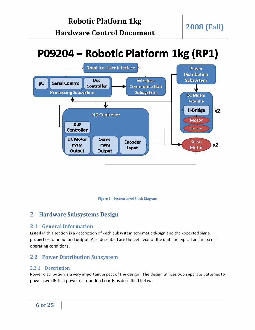
There are a total of seven subsystems, the Graphical User Interface, the Wireless Communications
subsystem, the Power Distribution subsystem, the Processing subsystem, the Motor Module Controller
subsystem, and lastly the Motor Module subsystem. A block diagram of these subsystems and their
interconnections is displayed in Figure 1.
The Graphical User Interface (GUI) is a software application written in JAVA and is thusly cross platform
compatible. Any operating system running the JAVA JRE (Java Runtime Environment) will be able to run

Robotic Platform 1kg 2008 (Fall)
Hardware Control Document
5 of 25
the GUI client software. The details of the GUI are described in the Interface Control Document (ICD).
Please see section 5 below for the location of the ICD.
The Wireless Communications subsystem is a subsystem dedicated to maintaining wireless control over
the robotic platform. The details of the communication properties and communication protocol of this
subsystem are described in the ICD. Please see section 5 below for the location of the ICD.
The Processing subsystem is the computational heart of the robotic platform. This subsystem contains
the processing core where all commands issued are computed through the communication channel into
motor controls and sensor feedback to the user. The details of this subsystem are not relevant within
the scope of the ICD. For more information please reference the Customer Needs, Design Specifications,
and any design documentation that may pertain to the Processing subsystem.
The Motor Module Controller subsystem and subsequent Motor Module subsystem are the logic and
device systems for actuating a motor. The Motor Module Controller subsystem contains logic to actuate
a motor, but does not contain the motor or driver circuitry itself. The controller subsystem simply
generates the timing and control signals, which are then fed into the Motor Module subsystem. There
are a variety of Motor Module controllers for the various supported motors. DC and Stepper motors
required extra controller and timing circuitry to operate, while Servos require only Pulse Width
Modulation (PWM) input. DC and Stepper motors require PWM inputs as well. Moving PWM generation
responsibility off chip onto a separate microcontroller, identified in the diagram as the PID Controller
module will allow for increased system modularity and less load on the core processing system.
The Motor Module system is not part of the RP1 control system platform, but is mentioned here only for
clarity of the design. The Motor Module will interface with the control system through the electrical
interface defined in the ICD. Please see section 5 below for the location of the ICD. The Motor Module is
expected to utilize the timing signals specified in this interface to control driver circuitry and the motor.
The driver circuitry, whether this may be a motor H-Bridge or some other device, shall be contained
within the Motor Module itself and not within the RP1 control system.
Robotic Platform 1kg 2008 (Fall)
Hardware Control Document
6 of 25
Figure 1 - System Level Block Diagram
2 Hardware Subsystems Design
2.1 General Information
Listed in this section is a description of each subsystem schematic design and the expected signal
properties for input and output. Also described are the behavior of the unit and typical and maximal
operating conditions.
2.2 Power Distribution Subsystem
2.2.1 Description
Power distribution is a very important aspect of the design. The design utilizes two separate batteries to
power two distinct power distribution boards as described below.

Robotic Platform 1kg 2008 (Fall)
Hardware Control Document
7 of 25
2.2.2 9V Power Distribution System
A 9V battery and distribution system is used to supply power to the microcontroller and other logic
subsystems. The current is limited to less than 700mA by a fuse at the input. A status LED is used to
indicate the operation of the system and a power sense output is used to supply a reading of the voltage
input. The 9V input is fed through a 5V regulator and subsequently fed to four identical 5V outputs.
Capacitors are utilized at both the input and output of the regulator to improve stability and prevent
rapid changes in current. This current is again limited through the use of a fuse to under 500mA. All
fuses are mounted with fuse clips to provide ease of access and replacement as necessary.
Figure 1 - 9v Power Distribution
Robotic Platform 1kg 2008 (Fall)
Hardware Control Document
8 of 25
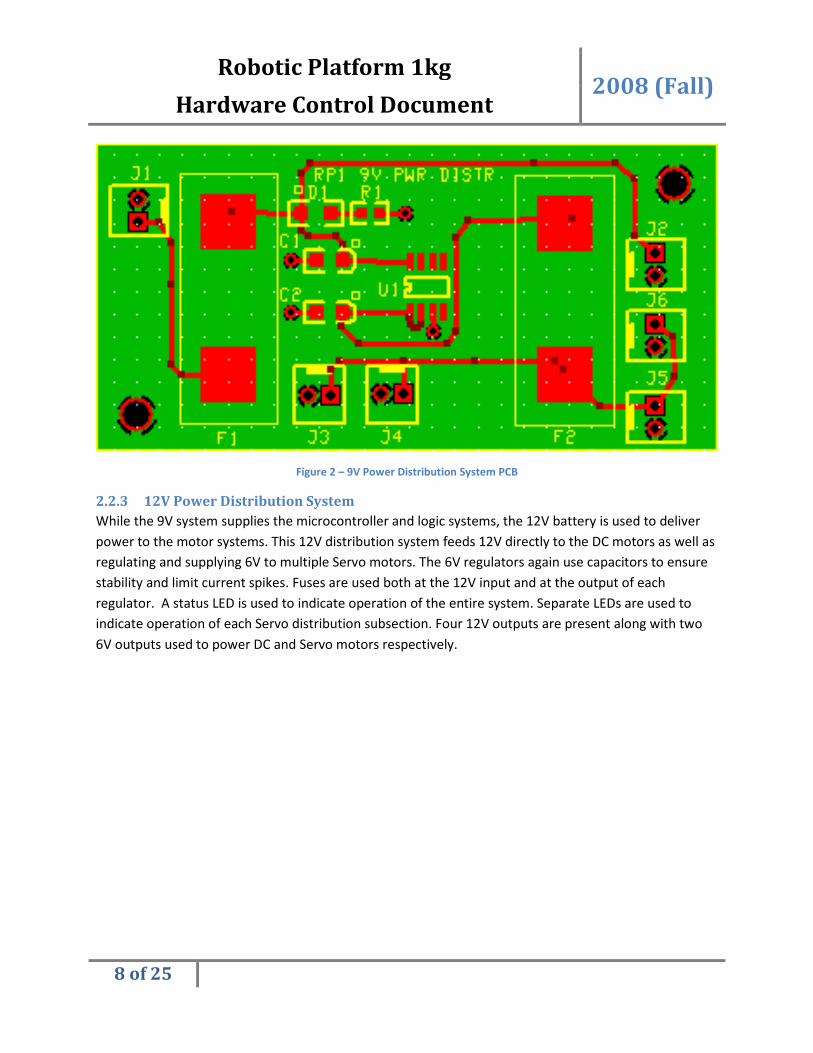
Figure 2 – 9V Power Distribution System PCB
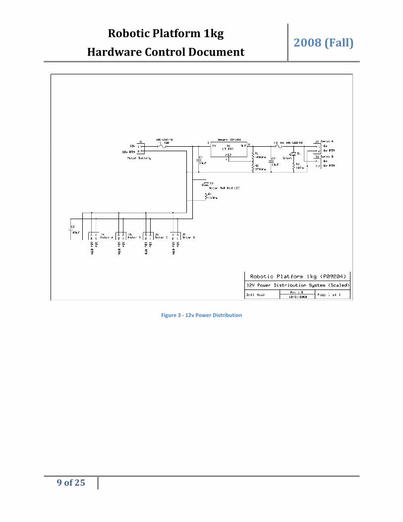
2.2.3 12V Power Distribution System
While the 9V system supplies the microcontroller and logic systems, the 12V battery is used to deliver
power to the motor systems. This 12V distribution system feeds 12V directly to the DC motors as well as
regulating and supplying 6V to multiple Servo motors. The 6V regulators again use capacitors to ensure
stability and limit current spikes. Fuses are used both at the 12V input and at the output of each
regulator. A status LED is used to indicate operation of the entire system. Separate LEDs are used to
indicate operation of each Servo distribution subsection. Four 12V outputs are present along with two
6V outputs used to power DC and Servo motors respectively.
Robotic Platform 1kg 2008 (Fall)
Hardware Control Document
9 of 25
Figure 3 - 12v Power Distribution
Robotic Platform 1kg 2008 (Fall)
Hardware Control Document
10 of 25
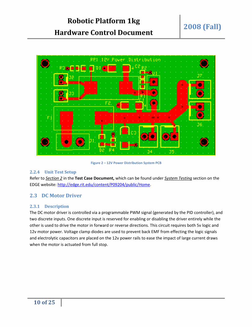
Figure 2 – 12V Power Distribution System PCB
2.2.4 Unit Test Setup
Refer to Section 2 in the Test Case Document, which can be found under System Testing section on the
EDGE website: http://edge.rit.edu/content/P09204/public/Home.
2.3 DC Motor Driver
2.3.1 Description
The DC motor driver is controlled via a programmable PWM signal (generated by the PID controller), and
two discrete inputs. One discrete input is reserved for enabling or disabling the driver entirely while the
other is used to drive the motor in forward or reverse directions. This circuit requires both 5v logic and
12v motor power. Voltage clamp diodes are used to prevent back EMF from effecting the logic signals
and electrolytic capacitors are placed on the 12v power rails to ease the impact of large current draws
when the motor is actuated from full stop.

Robotic Platform 1kg 2008 (Fall)
Hardware Control Document
11 of 25
2.3.2 Design Schematic
Figure 3 – Schematic of DC motor driver
2.3.3 PCB Layout
Robotic Platform 1kg 2008 (Fall)
Hardware Control Document
12 of 25
Figure 4 – PCB of DC motor driver
2.3.4 Unit Test Setup
Refer to Section 3 in the Test Case Document, which can be found under System Testing section on the
EDGE website: http://edge.rit.edu/content/P09204/public/Home.
2.4 Proportional Integral Derivative (PID) Controller
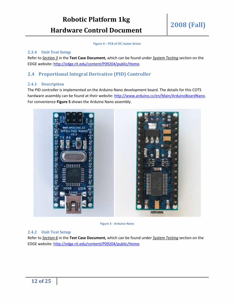
2.4.1 Description
The PID controller is implemented on the Arduino Nano development board. The details for this COTS
hardware assembly can be found at their website: http://www.arduino.cc/en/Main/ArduinoBoardNano.
For convenience Figure 5 shows the Arduino Nano assembly.
Figure 5 - Arduino Nano
2.4.2 Unit Test Setup
Refer to Section 6 in the Test Case Document, which can be found under System Testing section on the
EDGE website: http://edge.rit.edu/content/P09204/public/Home.
Robotic Platform 1kg 2008 (Fall)
Hardware Control Document
13 of 25
2.5 Microcontroller
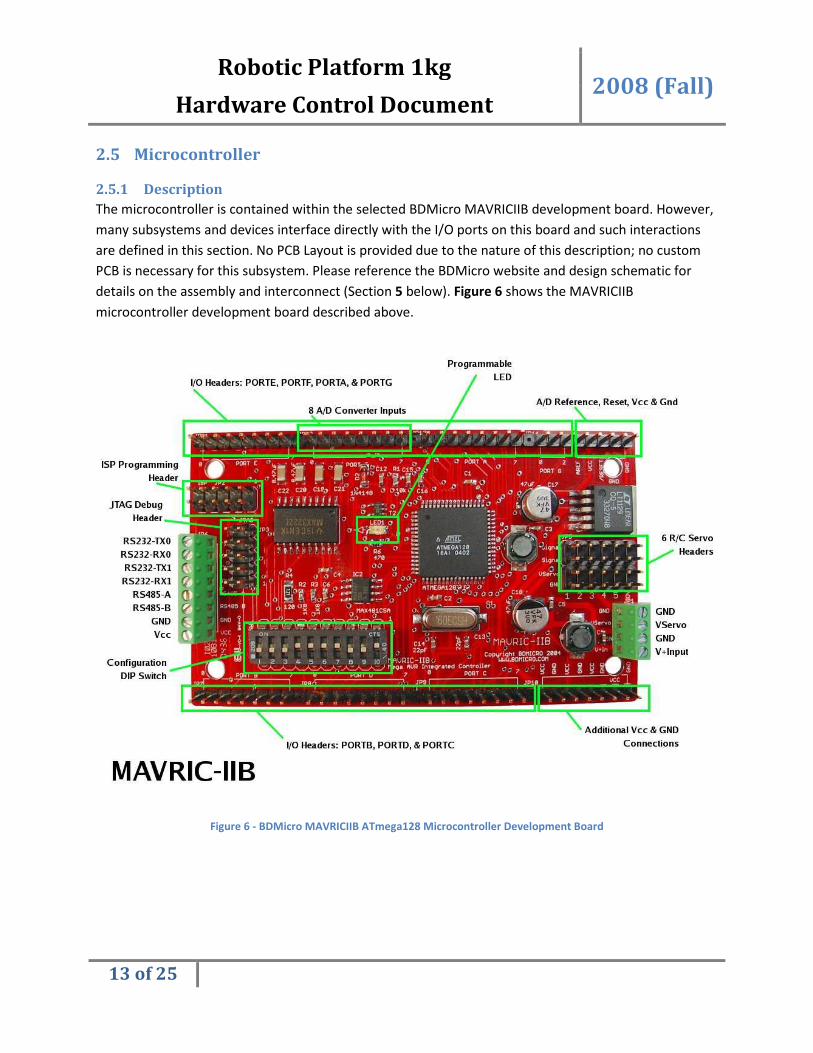
2.5.1 Description
The microcontroller is contained within the selected BDMicro MAVRICIIB development board. However,
many subsystems and devices interface directly with the I/O ports on this board and such interactions
are defined in this section. No PCB Layout is provided due to the nature of this description; no custom
PCB is necessary for this subsystem. Please reference the BDMicro website and design schematic for
details on the assembly and interconnect (Section 5 below). Figure 6 shows the MAVRICIIB
microcontroller development board described above.
Figure 6 - BDMicro MAVRICIIB ATmega128 Microcontroller Development Board
Robotic Platform 1kg 2008 (Fall)
Hardware Control Document
14 of 25
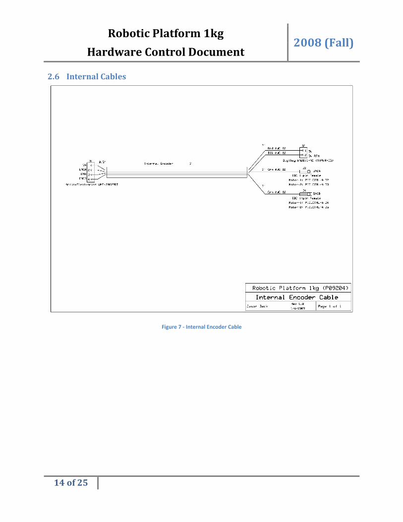
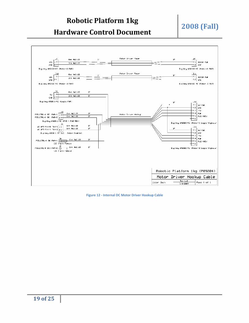
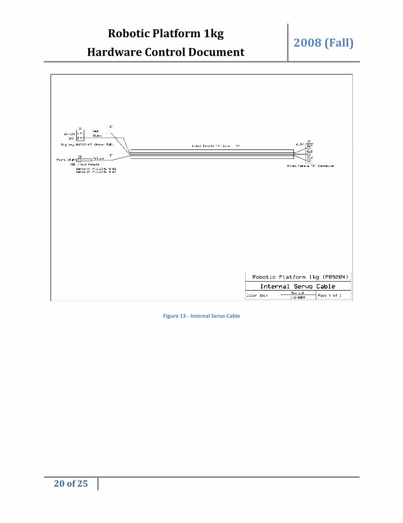
2.6 Internal Cables
Figure 7 - Internal Encoder Cable
Robotic Platform 1kg 2008 (Fall)
Hardware Control Document
15 of 25
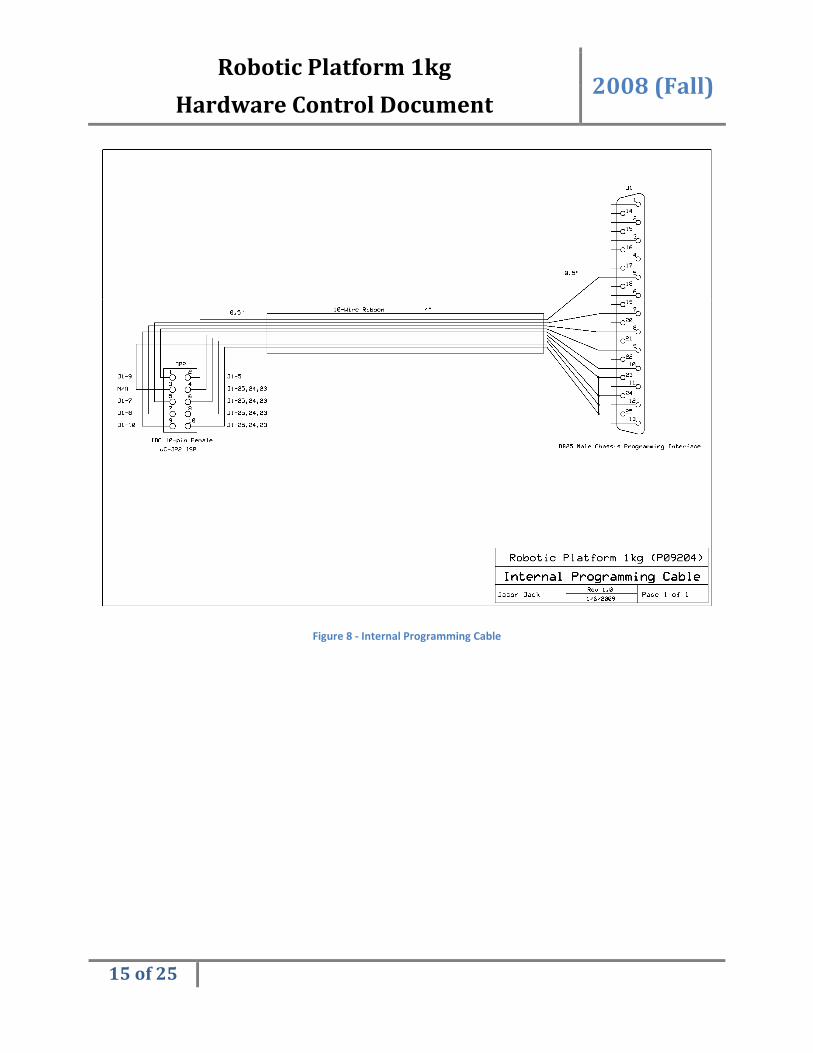
Figure 8 - Internal Programming Cable

Robotic Platform 1kg 2008 (Fall)
Hardware Control Document
16 of 25
Figure 9 - Internal Power-In Cable

Robotic Platform 1kg 2008 (Fall)
Hardware Control Document
17 of 25
Figure 10 - Internal Serial Cable
Robotic Platform 1kg 2008 (Fall)
Hardware Control Document
18 of 25
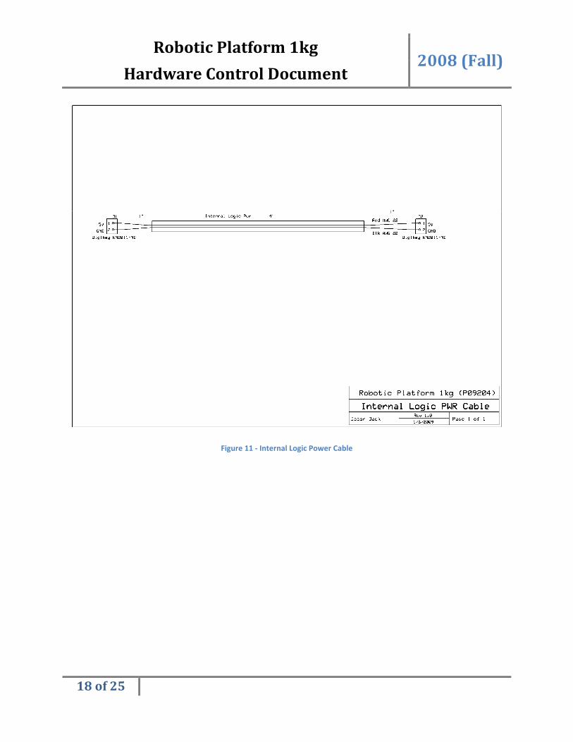
Figure 11 - Internal Logic Power Cable
Robotic Platform 1kg 2008 (Fall)
Hardware Control Document
19 of 25
Figure 12 - Internal DC Motor Driver Hookup Cable
Robotic Platform 1kg 2008 (Fall)
Hardware Control Document
20 of 25
Figure 13 - Internal Servo Cable

Robotic Platform 1kg 2008 (Fall)
Hardware Control Document
21 of 25
Figure 14 - Internal TWI Cable
Robotic Platform 1kg 2008 (Fall)
Hardware Control Document
22 of 25
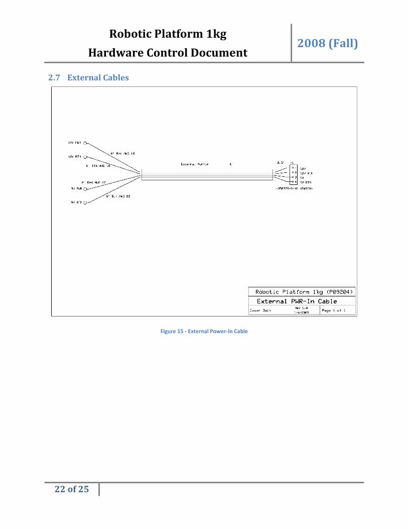
2.7 External Cables
Figure 15 - External Power-In Cable

Robotic Platform 1kg 2008 (Fall)
Hardware Control Document
23 of 25
Figure 16 - External DC Motor Hookup Cable
3 Hardware Wiring Below is a color coded internal and external wiring diagram. For users who are concerned only with
external wiring please disregard everything within the control box chassis. For information regarding the
pins to which each connector mates with please refer to the appropriate cable schematic in Sections 2.6
and 2.7.

Robotic Platform 1kg 2008 (Fall)
Hardware Control Document
24 of 25
3.1 Interconnect Wiring Diagram
Figure 17 - Interconnect Wiring Diagram
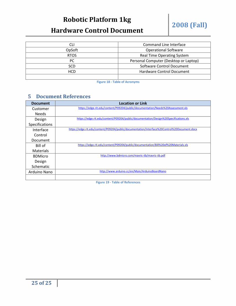
4 Acronyms
Acronym Description
RP1 Robotic Platform 1
ICD Interface Control Document
GUI Graphical User Interface
JRE JAVA Runtime Environment
Robotic Platform 1kg 2008 (Fall)
Hardware Control Document
25 of 25
CLI Command Line Interface
OpSoft Operational Software
RTOS Real Time Operating System
PC Personal Computer (Desktop or Laptop)
SCD Software Control Document
HCD Hardware Control Document
Figure 18 - Table of Acronyms
5 Document References
Document Location or Link
Customer
Needs
https://edge.rit.edu/content/P09204/public/documentation/Needs%20Assessment.xls
Design
Specifications
https://edge.rit.edu/content/P09204/public/documentation/Design%20Specifications.xls
Interface
Control
Document
https://edge.rit.edu/content/P09204/public/documentation/Interface%20Control%20Document.docx
Bill of
Materials
https://edge.rit.edu/content/P09204/public/documentation/Bill%20of%20Materials.xls
BDMicro
Design
Schematic
http://www.bdmicro.com/mavric-iib/mavric-iib.pdf
Arduino Nano http://www.arduino.cc/en/Main/ArduinoBoardNano
Figure 19 - Table of References