Embed Size (px)
Citation preview

1

2
Section 1 Summary of PDR Report 1.1 Team Summary 1.1.a School Name: Harding University 1.1.b Location: 915 E. Market Ave. Searcy, AR 72149 1.1.c Mentors: Edmond W. Wilson, Jr., Ph.D. James E. Mackey, Ph.D. David Stair 1.2 Launch Vehicle Summary 1.2.a Size: 3.9” ID, ~4.0” OD, ~9’ Full Length 1.2.b Motor Choice: K-265 Contrail Rockets Hybrid, 54mm 1.2.c Recovery System: Drogue - 24” Classic II Sky Angle Parachute Main - 60” Classic II Sky Angle Parachute PerfectFlite Ejection Charges 1.3 Payload Summary 1.3.a Name: REMSPEC 1.3.b Purpose: To collect emission spectra from the exhaust plume of the hybrid rocket motor, in order to study the spectra in situ for changes in the burn profile due to airflow and forward motion. 1.3.c Input: Light from the hybrid motor exhaust plume 1.3.d Output: Analog signal in time proportional to optical intensity of the portion of the spectrum incident on the photodiode 1.3.e Components: Fiber optic cable for presentation of light to the diffraction grating Diffraction grating for dispersion of the light source onto a mirror Motor for positioning of the mirror to sweep entire spectrum across the photodiode detector Photodiode detector for sampling spectrum as a time- based analog signal; will sample many spectra throughout the motor burn Eagle Tree Systems Flight Data Recorder with Dual Channel A/D Input Board for acquisition and synchronization of spectra signals

3
Section 2 Changes made since Proposal 2.1 Changes made to Vehicle Criteria
2.1.a The only major change made to the vehicle design or purpose since the Proposal has been a reduction of the number of fins from four to three, in order to decrease the overstability margin of the original rocket design.
2.2 Changes made to Payload Criteria
Several major changes have been made to the payload design, although the original purpose remains unchanged.
2.2.a A single photodiode will be used, instead of a photodiode array. The photodiode array has presented issues in interfacing and with cost in the past, so a single photodiode will be employed instead, with a rotating mirror assembly attached to a serve to allow sampling of the entire dispersed spectrum as a single analog time signal.
2.2.b The Atmel AVR microprocessor will no longer be used for data acquisition, as several issues in interfacing the subsystem with a telemetry subsystem arose. Since all cost-feasible telemetry systems include flight computers and data recorders, the original AVR microprocessor would be redundant and unnecessary. An Eagle Tree Systems Flight Data Recorder will replace this device as the data acquisition and storage subsystem.
2.2.c The Emhiser Research Telemetry Transmitter and Receiver package will not be employed due to budget requirements; further research revealed this system to be intended for much larger, possibly suborbital, rockets. An Eagle Tree Systems Seagull-HD Telemetry Transmitter and Receiver package will replace this device as the telemetry subsystem.
2.3 Changes made to Activity Plan
Due to several setbacks in arranging launch dates and the change in several project due dates, all activities listed on the timeline have been rescheduled to later times. The lack of available work time between the PDR and the CDR due to the holiday recess has also complicated scheduling. No activities have been removed or added; an updated timeline may be found in Section 5.1.b.

4
Section 3 Vehicle Criteria 3.1 Selection, Design, and Verification of Launch Vehicle
3.1.a Mission Statement, Requirements, and Mission Success Criteria The 2008-2009 Harding University “Flying Bison” ULSI Team is committed to the design, construction, launch, and safe recovery a reusable high-powered rocket for the study of hybrid motor exhaust plume emission spectra, with a target altitude of 5,280 feet. Critical Requirements for Project per SOW
• The vehicle shall carry a scientific payload. • The vehicle shall deliver the science payload to a specific altitude of
5,280 feet. • The launch vehicle and science payload shall be designed to me
recoverable and reusable. • Data from the science payload shall be collected, analyzed, and
reported by the team following the scientific method. • A tracking device shall be placed on the vehicle allowing the rocket
and payload to be recovered after launch. • Only commercially-available, NAR-approved motors shall be used. • All teams much launch their full-scale rocket prior to launch day. • The maximum amount teams may spend on the rocket and payload
is $5000 total. Mission Success Criteria
• Ignite and fire hybrid rocket motor at launch (no motor failure). • Sustain structural integrity throughout flight, including landing and
recovery. • Meet payload success criteria (see Payload Criteria, 4.3.b). • Reach 5,280-foot target altitude with minimal error. • Separate vehicle at apogee; deploy drogue parachute. • Separate vehicle at 800 feet; deploy main parachute. • Recover scientific payload and launch vehicle with only cosmetic
damage.
3.1.b Major Milestone Schedule September 1 – Project Initiation December 3 – Scientific Payload Design Complete December 5 – Launch Vehicle Design Complete

5
January 22 – REMSPEC Manufacture Complete – Recovery Subsystem Verification (Bench Test) – Data Acquisition Subsystem Verification (Bench Test) – Telemetry Subsystem Verification (Bench Test) – Tracking Subsystem Verification (Bench Test) January 30 – Propulsion Subsystem Verification (Test Stand Firing) February 6 – Launch Vehicle Airframe Manufacture Complete February 13 – Airframe & Recovery Subsystems Verification (Test Flight) – REMSPEC Subsystem Verification (Bench Test) February 20 – Integrated Scientific Payload Verification (Bench Test) – Integrated Scientific Payload Verification (Bench Test) February 27 – Integrated Systems Verification (Test Flight)
3.1.c Systems and Subsystems Scientific Payload
The scientific payload is required to collect light from hybrid motor exhaust plume during burn, sample the spectrum of the light as an analog signal in time, store this data in non-volatile memory for later recovery, and transmit this data to the ground wirelessly for analysis in real time. Selection rationale, concepts, subsystems, and performance characteristics are described in Section 4.1. Failure of the scientific payload system or any of its subsystems during flight involves several unique failure cases. If the REMSPEC subsystem fails during flight, the scientific payload will fail absolutely. In order to minimize risk of this failure case, the REMSPEC will be thoroughly bench-tested in collecting spectra from real hybrid rockets fired on our rocket test stand. If the data acquisition subsystem fails during flight, the scientific payload will fail absolutely. Once again, this subsystem will be bench-tested to minimize this risk, both against arbitrary analog signals and when interfaced with the REMSPEC. If the telemetry subsystem fails during flight, the ability to receive spectra in real-time will be lost, but the spectra will be stored in the data
Launch Vehicle
Scientific Payload
Tracking Propulsion Recovery
Telemetry Data Acquisition
[Spectrometer Name]
GPS Telemetry Hybrid Rocket
Support System
Avionics Parachutes

6
acquisition subsystem’s non-volatile memory, and will be recovered along with the launch vehicle. It should be noted that a failure of the telemetry subsystem would also affect the tracking system. The recovery system has been deliberately designed to be completely independent of the scientific payload system The electronics involved in the scientific payload play no role in the avionics subsystem; in fact, the two systems are physically separated by the drogue parachute chamber.
Tracking
The requirements of the tracking system are to determine the position of the launch vehicle relative to the launch site throughout the flight, and to transmit this information to the ground to facilitate recovery of the rocket and scientific payload after launch. The tracking system will continually poll the GPS subsystem for the location of the rocket system, and pass the location to the telemetry subsystem, which will bundle GPS coordinates of the rocket in a packet with other data to be transmitted. This data will be received on the ground and uploaded in real time to a laptop computer for tracking and plotting purposes. An Eagle Tree Systems (ETS) 5Hz GPS Expander has been chosen as the GPS subsystem. It will interface with the ETS Flight Recorder, which will route the GPS data to the telemetry subsystem. This component has an update rate of 5Hz, which will give approximately 100 data points throughout the flight. An ETS Seagull-HP 900 MHz 200 mW Transmitter has been selected as the Telemetry subsystem. It will be paired with a Seagull Dashboard Receiver for a 1.2-mile wireless signal range; if necessary, a yagi antenna will be constructed to increase the range by up to 2.4 miles. This transmitter operates in the frequency range of 902 – 928 MHz. Failure of the tracking system or any of its subsystems during flight will result in loss of GPS data at the time of failure. Risks from failure include an inability to quickly locate the launch vehicle after flight; in order to minimize this risk, the recovery system has been designed to return the launch vehicle within 1000 feet of the launch site. It should be noted that a failure of the telemetry subsystem would also affect the scientific payload subsystem.
Launch Vehicle
Scientific Payload
Tracking Propulsion Recovery
Telemetry Data Acquisition
[Spectrometer Name]
GPS Telemetry Hybrid Motor
Support System
Avionics Parachutes

7
Propulsion The requirements of the propulsion system are to impart a controlled thrust to the launch vehicle, in a manner conducive to stable flight, which will bring the vehicle to an altitude of 5280 feet with minimal error. The objectives of the scientific payload place an additional requirement on the system; it must employ a hybrid rocket motor. The propulsion system will ignite by passing a current through an electric match using the support subsystem, which will ignite several Pyrex pellets and begin a controlled oxidation reaction between the nitrous oxide and the fuel grain. This reaction is directed out the nozzle of the hybrid rocket motor, which generates a thrust that propels the rocket. The reactants ejected out of the nozzle are luminous, and can be analyzed with an emission spectrometer (REMSPEC) in order to learn about the reaction in the motor. A Contrail Rockets K-265SP hybrid rocket motor will be used as the Hybrid Motor subsystem. This motor has a total weight of 2.085 kg, with a recovery weight of 1.814 kg, and a nitrous oxide volume of 1490 cc. The burn time for this motor is 6.26 seconds with a total impulse of 1684, maximum thrust of 777.1 N, and average thrust of 268.94 N. A Pratt Hobbies RTLS-M1 Remote Tanking and Launching System will be used as the support subsystem. This module can control the filling of the Hybrid Motor subsystem with nitrous oxide, dump the nitrous oxide from the motor if necessary, and ignite the hybrid motor, all from a location 200 feet away from the launch pad. The igniter generates a 12V across the electric match with a 3000 mAh rechargeable battery. Failure of the propulsion subsystem clearly presents a great risk to the success of the project; in order to mitigate such risk, the motor will be test fired on our test stand and test flights will be conducted.
Launch Vehicle
Scientific Payload
Tracking Propulsion Recovery
Telemetry Data Acquisition
[Spectrometer Name]
GPS Telemetry Hybrid Motor
Support System
Avionics Parachutes

8
Recovery The requirements of the recovery system are to control the path and rate of descent of the launch vehicle after apogee so that the launch vehicle will pose no safety issue and will suffer no damage that would prevent an immediate reequip and launch. The recovery system will employ black powder charges to separate the rocket at two points along the airframe, in order to release the drogue and main parachutes. Two redundant systems for igniting the charges will exist, both of which will be configured to fire distinct ejection charges at apogee and at an altitude of 800 feet, corresponding to deployment of the drogue and main parachutes, respectively. Nomex flame guards and flame-resistant wadding will be used liberally to prevent any burning or melting of parachutes or recovery harness. A PerfectFlite MAWD flight computer and a G-Wiz LCX flight computer will serve as the cores for two completely redundant avionics subsystems. Both flight computers require a 9V operating voltage. The MAWD detects apogee with a barometric altimeter, which was likely the cause of the failure of last season. In order to prevent the barometer from detecting a premature apogee, the Mach timer feature will be employed to prevent the MAWD from firing any charges until after motor burn is completed (6.26 s). The LCX detects apogee with an accelerometer, which should not present the same risk as the MAWD. The MAWD audibly reports the peak altitude with a series of beeps after the flight is completed; this report will give the official peak altitude for the competition. The ejection charges will be built from the PerfectFlite ejection charge kit, which does not require the use of flashbulbs. Pyrex powder will provide the force necessary to separate the airframe. Ejection charges will be located so that the force of detonation will drive the shock cord and parachute out of the airframe, instead of into the airframe, to ensure quick deployment of the parachutes. Much of the recovery harness for the main parachute will be housed in the Public Missiles Intellicone, which has been cut and fitted with phenolic tubing. The parachutes subsystem consists of the drogue parachute, the main parachute, and the shock cord employed by each. The drogue parachute will be a b3 Rocketry 24” Classic II Sky Angle parachute, which, given our current mass projections, will give the launch vehicle
Launch Vehicle
Scientific Payload
Tracking Propulsion Recovery
Telemetry Data Acquisition
[Spectrometer Name]
GPS Telemetry Hybrid Motor
Support System
Avionics Parachutes

9
an approximate descent rate of 61 feet per second. The mass has been predicted to be approximately 14 pounds by entering specific masses for each component in RockSim, either from vendor specifications or from direct measurement when possible. 15 yards of 9/16” tubular nylon shock cord will secure this parachute to the avionics and scientific payload sections, and a Nomex flame guard will protect the parachute from the separation charge. The main parachute will be a b3 Rocketry 60” Classic II Sky Angle parachute, which will give the launch vehicle an approximate descent rate of 20 feet per second. 10 yards of 9/16” tubular nylon cord will secure this parachute to the interior of the nose cone and the avionics section, and a Nomex flame guard will protect this parachute as well.
3.1.d Dimensional Drawing
Figure 1: Dimensional Drawing of the Launch Vehicle. The brown section on the left side of the drawing houses the avionics subsystem; the brown section to the right houses the scientific payload and tracking systems. The leftmost section with a green rectangle houses the main parachute; the right section with a green rectangle houses the drogue.

10
3.2 Mission Performance Predictions 3.2.a Mission Performance Criteria
• Performance of the launch vehicle in flight will be subject to these criteria: • Vehicle reaches velocity for stable flight before leaving launch guide. • Vehicle maintains stable flight throughout. • Vehicle does not “weathercock” unreasonably. • Vehicle reaches apogee at target altitude. • Vehicle descends at 61 feet/sec under drogue. • Vehicle descends at 20 feet/sec under main.
3.2.b Simulations
Figure 2: Plots of Simulated Flight Profile.
These are the flight profile plots for a representative simulation in RockSim, with the first at apogee and the second at landing. All simulations were conducted with environmental conditions specific to Huntsville, Alabama, including average weather for the month of April. After running six simulations under Huntsville conditions, the average peak altitude for the rocket was 5800 feet. While this simulation factors in the masses of each component as best as can be predicted, from experience, the mass of the rocket will be greater in reality. The simulated mass was approximately 14 pounds. This simulated altitude gives a large, comfortable margin for additional weight in case of unforeseen design changes.

11
Figure 3: K-265SP Thrust Curve.
This is the K-265SP motor thrust curve from certification testing provided to Contrail Rockets by Tripoli Rocket Association.
3.2.c Stability Predictions Returning to the drawing in Section 3.1.d, the red dot shows the location of the center of pressure, and the blue dot shows the location of the center of mass. The center of pressure was calculated using the Barrowman stability equations. The simulated center of gravity is located at 60 inches from the nose of the rocket; the simulated center of pressure is located at 76.2 inches from the nose of the rocket. The resulting stability margin is 4.02 body diameters overstable, which increases to 4.67 as the rocket motor expends its fuel. With a user-specified stable-flight velocity of 44 ft/s, the rocket reaches the velocity for stable flight at 5 feet above the launch pad. Taking into account the location of the launch lugs, an eight-foot long launch guide should provide ample time for the rocket to accelerate into stable flight.
3.3 Payload Integration The need to integrate the scientific payload system (and the other subsystems) is understood; the REMSPEC has been designed as a <3.9” OD cylinder to allow the instrument to be fit into a coupler tube section. In manufacturing of the airframe, a piece of aluminum tubing will be run through small holes in the centering rings alongside the motor mount tube, to allow a fiber optic cable access to the exhaust plume for collection of light. Integration considerations for the data acquisition and telemetry subsystems will begin upon the arrival of these parts. Structurally, the launch vehicle will be designed to fly without the scientific payload and tracking systems; this scenario will actually occur during the first test flight. These systems will be housed in an 8” section

12
of fiberglassed coupler tube between the motor mount and the drogue parachute sections. Three ¼” stainless steel threaded rods will run through the tube and affix the bulkheads firmly to each end.
3.4 Launch Operation Procedures 3.4.a Launch System
The support subsystem will provide all necessary hybrid motor support, including a oxidizer fill control and ignition. What type of launch system will be used must be discussed with the panel members and support team in order to determine what launch guide types will be available at the launch event. If the panel is uncertain, the launch vehicle will be designed to launch off both a rod guide and a rail guide.
3.4.b Final Assembly and Launch Procedures 1. Upon arrival at the launch site, meet with range personnel and
determine the launch system to be used. 2. Build ejection charges and position disconnected in the airframe. 3. Fold and pack parachutes, shock cord, and flame-resistant
materials into rocket. 4. Build hybrid rocket motor; mount into launch vehicle. 5. Power up scientific payload and tracking systems, interface with
laptop, and determine operational status. 6. Test telemetry subsystem. 7. Connect ejection charges to avionics subsystem; use flight
computers to test continuity on all charges. 8. Assemble sections of airframe and insert power pins to avoid
draining batteries during wait. 9. Report ready status to range personnel. 10. When cleared, set rocket on launch guide and attach oxidizer fill
line to the support subsystem. 11. Check igniter leads for “disarmed” state, and then connect to the
motor igniter leads. 12. Remove power pins to activate all electronics. 13. Report to range personnel. 14. When cleared, fill hybrid motor with nitrous oxide using support
subsystem until venting of fluid occurs. 15. Notify range personnel to begin countdown. 16. At “three,” discontinue filling nitrous. 17. Ignite motor. 18. Track rocket during flight visually for safety. 19. Recover rocket.

13
3.5 Safety and Environment (Vehicle)
3.5.a Safety Officer The Safety Officer for the Harding University Flying Bison 2009 USLI Rocket team is Greg Lyons. Greg has been in the program for two years and is well equipped to fill this position. He will be responsible for monitoring all potentially hazardous activity throughout the project, and he will report to the Range Safety Officer during inspection and in the event of any safety concerns.
3.5.b Failure Analysis Several failure cases of the propulsion system exist. A failure of the hybrid rocket motor subsystem would include three scenarios, and a failure of the support system would include one scenario. The first scenario would be a catastrophic failure of the motor. The Harding University USLI team has been building hybrid rocket motors from Contrail Rockets for three years. We will observe and follow all procedure in constructing and launching our motor; a catastrophic failure is highly unlikely given proper construction procedure. Clearly, such a scenario would completely compromise the launch vehicle. The second scenario would involve an incomplete fill of the nitrous oxide tank, which occurred the first season that Harding submitted a launch vehicle to the USLI competition. This scenario poses no risk to safety, assuming no other systems fail, but the rocket would not reach the target altitude. The possibility of this failure risks absolutely compromising the success of the mission. This scenario will be avoided by using binoculars to observe the vent line of the motor, and to only ignite the motor when nitrous has been venting for several seconds. The motor must be ignited immediately after the fill is turned off, so arrangements will be made with the Range Safety Officer to allow a shortened count-down (as was done last season). The third and fourth scenarios both involve a failure to ignite, whether in the third case by a failure of the motor itself or in the fourth case by a failure of the support subsystem. Both scenarios will present the same characteristics, and in both, the Safety Officer will disconnect the ignition line from the support subsystem and report to the Range Safety Officer. Several failure cases of the recovery system also exist. A failure of the avionics subsystem would involve two scenarios, and a failure of the parachutes subsystem would involve one scenario. The first scenario would involve an early firing of an ejection charge during ascent. As was witness last season, such an event creates forces on the rocket that cannot be sustained, and the system would

14
lose structural integrity and become a safety concern. In order to mitigate this risk, redundant avionics subsystems are employed, and the barometric altimeter flight computer (MAWD) will have ejection-charge firing locked out until after the motor burn is finished. The LCX flight computer detects apogee with an accelerometer, and will not fire if the rocket is still coasting upwards. The second scenario would involve a failure of an ejection charge to separate and deploy a parachute. There are three cases: Failure to deploy drogue, failure to deploy main, and failure to deploy any. The first case would likely result in an extremely large impulse on the launch vehicle, and the recovery harness or the airframe would certainly lose integrity. This would result in subassembly component entering free-fall from 800 feet, which would be hazardous to all bystanders. The second case would result in a slowed descent of the vehicle to the ground, which would allow bystanders ample time to avoid, but the velocity of impact would likely damage components of the payload. The third case would result in a ballistic trajectory of the launch vehicle, which would be very hazardous to all bystanders and personnel. In order to mitigate these risks, the redundant avionics system has been employed, and thorough bench testing of both flight computers will occur. The third scenario would involve a failure of a parachute to open due to tangling or some other circumstance. This scenario can usually be avoided by following the manufacturer’s folding and packing instructions, and by leaving the interior of the parachute section free from anything the fabric or shock cord could catch on.
3.5.c Personnel Hazards No hazardous chemicals are to be employed in this launch vehicle. The hybrid rocket motor components are completely inert until ignition, and are safe to handle in any situation until fully assembled and upright. The many legal and safety concerns associated with solid fuel ammonium perchlorate motors are not issues when using hybrid motors. Standard range safety procedure will be followed when igniting the rocket motor; this should prevent any danger to personnel and bystanders. Care must be taken in the assembly of the ejection charges, as an accidental detonation could be hazardous. Hot gas and ejecta from a charge detonating in an unsealed airframe section would be harmful to personnel, so when ejection charges are being attached to the flight computers, all unnecessary personnel will be instructed to stand clear. When in transport, the leads of ejection charges will be twisted together, to prevent ignition by static discharge.
3.5.d Environmental Concerns One of the reasons for current interest in hybrid rocket motors (and, incidentally, for our study of hybrid rocket motors) is the environmentally

15
friendly products of a burn when compared to solid and liquid fuel motors. We are confident that the Contrail Rockets K-265SP motor will have a minimal impact on the surrounding environment. The major combustion products are carbon dioxide, water and heat. No waste material will be left at the launch site, assuming the rocket is reasonably intact and can be located. There is the danger of fire before liftoff. However, proper safety procedures greatly minimize the chance for a fire at launch.

16
Section 4 Payload Criteria 4.1 Selection, Design, and Verification of Payload Experiment
4.1.a System-Level Design Review The Science Payload is a Rocket EMission SPECtrometer, REMSPEC, that will measure the emission spectrum of the exhaust plume of our hybrid rocket motor in the spectral range of 280 nm through 1000 nm at a rate of five times per second starting with ignition and continuing through burnout at approximately four seconds. See Figure 1. It consists of the following subsystems: Fiber optic cable light gathering subsystem – A jacketed 1 meter multimode fiber optic cable transparent from 280nm through 1000nm with a light collecting lens on one end is required to transmit the electromagnetic radiation from the hybrid rocket motor exhaust plume to the spectrometer. Monochromator subsystem – An ultraviolet-visible-near infrared monochromator covering the spectral range of 280 nm through 1000 nm that can record spectra at a rate of 5 Hz and having a spectral resolution of 1 nm is required. The detector must give good response throughout the entire spectral range and have a response time of 10 µs or better. The detector must produce a current proportional to the amount of radiation striking it. The plastic holographic transmission grating has 750 grooves per millimeter and is blazed to a 550 nm wavelength. It has a 23.5 dispersion angle. See Figure 2. Detector subsystem -- The detector must give good response throughout the entire spectral range and have a response time of 10 µs or better. The detector must produce a current proportional to the amount of radiation striking it. It must contain a signal conditioning unit to convert the current from the detector into a voltage and amplify the voltage so that the minimum and maximum radiation intensities are scaled to a voltage between 0 and 4 volts to match the analog to digital converters. Data recording subsystem – A digital to analog converter with at least 8 bits of resolution and a conversion time of 1 µ is needed to record the spectrum at a 5 Hz rate and a resolution of 1 nm spectral width. A clock is needed to synchronize the measurement process. Power supply subsystem – The entire Science Payload must operate using batteries. A 6 VDC capable of producing 100 mA and run for 2 hours on 4 AAA batteries.

17
Figure 1: Schematic Drawing of Science Payload.

18
Figure 5: Photograph of REMSPEC Monochromator.
Microcontroller subsystem – A microcontroller computer system is needed to initiate the data collection of the analog to digital converter and to record the data into a memory device that can later be read into a computer for data analysis after the flight. It must fit into a 4” diameter airframe and weigh less than 200 grams. It must have a clock in order to synchronize the data collected with time into flight.
4.1.b Payload Subsystem Descriptions Fiber optic cable light gathering subsystem – A multimode optical fiber will be attached to the airframe of the rocket. It will be mounted on one of the rocket fins and aimed at the middle of the rocket motor exhaust plume. The fiber will have a light collecting lens attached to gather the light from the optical emission produced by the rocket motor and focus it into the fiber optic cable. The optical emission from the motor will be transmitted through the fiber optic cable and focused onto the entrance slit of the monochromator.

19
Monochromator subsystem – The monochromator subsystem consists of an entrance slit that will transmit a narrow beam of the light from the end of the fiber optic cable. A light collecting and focusing lens directs the beam to a square rotating, front-surfaced silvered mirror and focuses it onto the detector. During a portion of each mirror rotation, the light beam is sent through transmission grating and the dispersed light is sent sequentially across a silicon photodiode detector to record the entire spectrum at a rate of once per mirror revolution. Detector subsystem -- The silicon photodiode detector converts the light incident on it to a current which is sent to a signal conditioning module that amplifies it and converts it to a voltage between zero and four volts. The voltage then is transmitted to the microcontroller for conversion to digital data and stored. Data recording subsystem– The analog voltages, which have been conditioned to produce a zero to four volt signal response, are converted to digital form using an analog to digital converter. Power supply subsystem – The entire Science Payload will run on batteries and requires a maximum of 6 VDC at 100 mA. It will run for several hours on 4 AAA batteries. Microcontroller subsystem -- All of the subsystems are controlled and monitored by a SeaGull HP High Powered Rocketry Package. The microcontroller has the following additional subsystems:
• Wireless Telemetry Transmitter, 900 Mhz, 200 mW • Dashboard Receiver • Flight Data Recorder • GPS Expander • SMA Dashboard Antenna • Pitot Tube
20
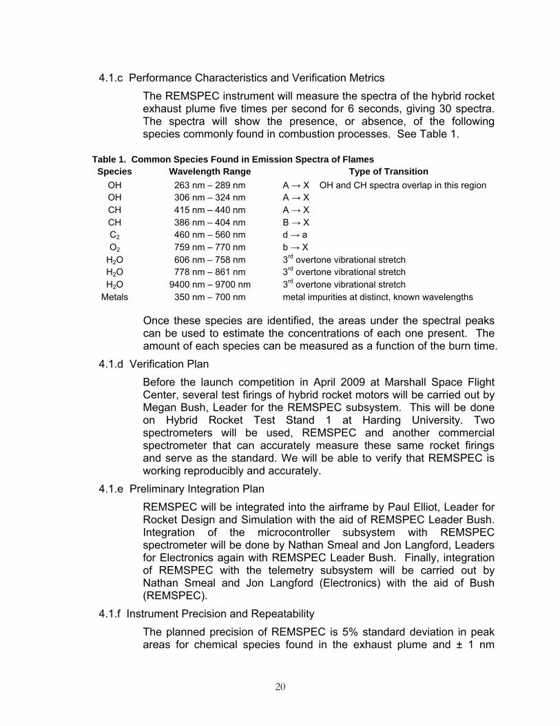
4.1.c Performance Characteristics and Verification Metrics The REMSPEC instrument will measure the spectra of the hybrid rocket exhaust plume five times per second for 6 seconds, giving 30 spectra. The spectra will show the presence, or absence, of the following species commonly found in combustion processes. See Table 1.
Once these species are identified, the areas under the spectral peaks can be used to estimate the concentrations of each one present. The amount of each species can be measured as a function of the burn time.
4.1.d Verification Plan Before the launch competition in April 2009 at Marshall Space Flight Center, several test firings of hybrid rocket motors will be carried out by Megan Bush, Leader for the REMSPEC subsystem. This will be done on Hybrid Rocket Test Stand 1 at Harding University. Two spectrometers will be used, REMSPEC and another commercial spectrometer that can accurately measure these same rocket firings and serve as the standard. We will be able to verify that REMSPEC is working reproducibly and accurately.
4.1.e Preliminary Integration Plan REMSPEC will be integrated into the airframe by Paul Elliot, Leader for Rocket Design and Simulation with the aid of REMSPEC Leader Bush. Integration of the microcontroller subsystem with REMSPEC spectrometer will be done by Nathan Smeal and Jon Langford, Leaders for Electronics again with REMSPEC Leader Bush. Finally, integration of REMSPEC with the telemetry subsystem will be carried out by Nathan Smeal and Jon Langford (Electronics) with the aid of Bush (REMSPEC).
4.1.f Instrument Precision and Repeatability The planned precision of REMSPEC is 5% standard deviation in peak areas for chemical species found in the exhaust plume and ± 1 nm
Table 1. Common Species Found in Emission Spectra of Flames Species Wavelength Range Type of Transition
OH 263 nm – 289 nm A → X OH and CH spectra overlap in this region OH 306 nm – 324 nm A → X CH 415 nm – 440 nm A → X CH 386 nm – 404 nm B → X C2 460 nm – 560 nm d → a O2 759 nm – 770 nm b → X
H2O 606 nm – 758 nm 3rd overtone vibrational stretch H2O 778 nm – 861 nm 3rd overtone vibrational stretch H2O 9400 nm – 9700 nm 3rd overtone vibrational stretch
Metals 350 nm – 700 nm metal impurities at distinct, known wavelengths

21
wavelength accuracy. The Science Payload is an integral part of the airframe and will use the same recovery procedures as the rocket itself. Data will be downloaded to a laptop computer once the rocket is recovered. As a redundancy, the data will also be sent during flight by telemetry to a computer on the ground.
4.2 Payload Concept Features and Definition 4.2.a Creativity and Originality
To our knowledge, no one has built a spectrometer specifically designed to operate during flight of a high powered rocket. The concept of a spinning mirror allows building the instrument without having to purchase an expensive photodiode linear array with its sophisticated electronics. This is a major factor when a malfunction and loss of the rocket is a distinct possibility.
4.2.b Uniqueness or Significance It is possible that no one has ever employed a spinning mirror spectrometer and the design is unique. The significance of these types of measurements is that it is moving us further to achieving the goals of our rocket research program at Harding University. The first goal is to determine what chemical species are present in hybrid rocket plumes both temporally and spatially as well as determine the amounts. The second goal is to use the above information during flight to provide a feedback loop to control (throttle) the rate of combustion. The third goal is the determine the impact of the firing on the environment (Green Chemistry).
4.2.c Suitable Level of Challenge In order to accomplish the tasks associated with the Science Payload, the team has to apply principles of spectroscopy, electronics, computer interfacing, including digital to analog conversions, and telemetry under very hostile conditions during the flight of a high powered rocket. This is a challenging project that is quite appropriate for college level juniors, seniors and beginning graduate students in chemistry, electrical and mechanical engineering.
4.3 Science Value 4.3.a Science Payload Objectives
The Science Payload Objectives are: • Obtain 30 measurements of the emission spectrum of rocket
exhaust plume beginning with rocket motor ignition and repeating at a frequency of 5 times per second for a total of 6 seconds.

22
The measurement will include the spectral range of 280 nm in the ultraviolet through 1000 nm in the near-infrared.
• Transmit the recorded emission spectra data wirelessly to a ground monitoring center during rocket flight.
• Identify chemical signatures in the rocket exhaust plume and graph the amount of each substance present as a function of time during the rocket burn.
4.3.b Payload Success Criteria The Payload Success Criteria is a successful flight returning at least three useable spectra stored in the onboard memory of the science payload.
4.3.c Variables Test measurement variables include the speed of the rotating mirror, the rate of conversion of the photodiode detector and analog to digital converter, rate of data storage and storage capacity of the computer memory. Also, the voltage produced by the photodiode detector is variable. All these variables will be tested multiple times before the FRR.
4.3.d Data Relevance and Error Analysis Optimal data collection would produce results that equal those of the commercial spectrometer which include 1 percent repeatability of the instrument under controlled laboratory conditions for both peak areas and wavelengths of the spectra. Plans are developed for full testing of the REMSPEC simultaneously with a commercial spectrometer both in the laboratory and using the Harding University Hybrid Rocket Test Stand 1 firing hybrid rocket fuel grains using nitrous oxide as the oxidizer.
4.3.e Experiment Process Procedures Science Payload Leader Megan Bush has carried out two test stand burns of a smaller hybrid rocket motor using nitrous oxide fuel. A commercial spectrometer was used to establish baseline spectra. The REMSPEC prototype has been completed and is now in the laboratory testing phase. A low pressure mercury vapor lamp will be used to produce spectra that are in industry standard for spectrometer testing in the wavelength range of REMSPEC. From this test, many of the accuracy metrics will be establish placing a limit on the accuracy and reproducibility of REMSPEC.

23
4.4 Safety and Environment (Payload) 4.4.a Safety Officer
The Safety Officer for the Harding University Flying Bison 2009 USLI Rocket team is Greg Lyons. Greg has been in the program for two years and is well equipped to fill this position.
4.4.b Failure Modes The Science Payload failure modes are: Battery failure. Fresh batteries will be installed in the Science Payload just prior to launch. Testing will be done before launch day to determine the length of time the batteries will have enough power to keep the instrument working. Failure to initiate operation of the spectrometer. Testing the spectrometer on the launch vehicle at least once before the competition is the only way to build confidence that REMSPEC will take data as planned. Failure of the mirror to rotate during flight. Thrust bearings will be installed on the motor to minimize the frictional forces encountered during a flight. Again, testing with a launch will help to minimize failure during competition.
4.4.c Personnel Hazards No chemicals are used in the Science Payload and the construction materials are commonly used, safe materials: plastics, copper wire, printed circuit boards, etc. There are no NAR rules that would cause safety concerns for this payload. The only conceivable danger would be if the rocket exploded and the tiny motor used to turn the mirror became a projectile. With the use of hybrid rockets, an explosion would be virtually impossible as the fuel grain is not an explosive material.
4.4.d Environmental Concerns The firing of a hybrid rocket has a minimal impact on the environment. The major combustion products are carbon dioxide, water and heat. No waste material will be left at the launch site, assuming the rocket is reasonably intact and can be located. There is the danger of fire before liftoff. However, proper safety procedures greatly minimize the chance for a fire at launch.

24
Section 5 Activity Plan 5.1 Budget Plan
Item Amount Rocket Airframe 300.00Parachutes and Safety Harness 100.00Construction Hardware and Consumables 200.00Perfect Flight MAWD 100.00Materials for Science Payload 600.00Contrail Rocketry Hybrid Motor System and Reloads 500.00Nitrous Oxide, Motor Fuel Grains, Launch Consumables 300.00NAR Level 1 and Level 2 Licensure 200.00Outreach 100.00Travel to Competition Launch at Marshall Space Flight Center (10 Travelers)
2600.00
Total Estimated Expense 5000.00 5.2 Timeline
October 8 • Proposal Due
October 20 • Proposal Submitted Late
October 24 • Notification of Selection
October 29 • Finalize Rocket Design and Drawings • USLI Teams Teleconference
November 12 • Establish Web Presence • Select Scientific Payload Design; Signal Type
November 28 • Finalize Telemetry and Data Acquisition Scheme • Preliminary Design Review Report Due
December 3 • Scientific Payload Design Complete

25
December 5 • Launch Vehicle Design Complete
Late January • NAR Level Two Certification Flight Attempts • Scale Model Flight
January 22 • REMSPEC Manufacture Complete • Recovery Subsystem Verification (Bench Test) • Data Acquisition Subsystem Verification (Bench Test) • Telemetry Subsystem Verification (Bench Test) • Tracking Subsystem Verification (Bench Test) • Critical Design Review Presentation Slides and CDR Report Due
January 30 • Propulsion Subsystem Verification (Test Stand Firing)
January 28 – February 6 • Critical Design Review
February – March • Test Flights of Competition Rocket • Phasing In of Systems as they are Completed
February 6 • Launch Vehicle Airframe Manufacture Complete
February 13 • Airframe & Recovery Subsystems Verification (Test Flight) • REMSPEC Subsystem Verification (Bench Test)
February 20 • Integrated Scientific Payload Verification (Bench Test) • Integrated Scientific Payload Verification (Bench Test)
February 27 • Integrated Systems Verification (Test Flight)
March 18 • Complete Test Flight of Rocket in Competition Format • Finalize Report on Motor Thrust Studies • Flight Readiness Review Presentation Slides and FRR Report Due
March 25 – April 3 • Flight Readiness Review

26
April 17 • Flight Hardware Check
April 18 • Launch Day
May 8 • Post-Launch Assessment Review Due • Finalize Report on Exhaust Plume Studies
May 25 • Announcement of Winning USLI Team
5.3 Outreach Summary
On December 2, 2008, Outreach Team member Cortney Owen and Team Official Ed Wilson held a water-bottle rocket competition afternoon for the fourth grade class at Westside Elementary in Searcy, Arkansas. Earlier in the semester, Owen and Wilson had visited the fourth grade classroom of Ms. Sherry Wilson (no relationship) to show the students how to build their rockets and to tell about NASA'sthe Mission to the Moon. They also explained about the USLI 2009 competition in which we were involved. The students and many parents were present for the competition. Prizes were given for the best design, highest flyer, longest hang time and most unique rocket. In all 20 students successfully flew and recovered their rockets. Three landed on the roof of the school and one hung in a tree. This only added to the excitement. Many of the parents and children expressed thanks for having this wonderful hands-on experience in science. Ms. Wilson, the teacher, was also very appreciative and felt the entire project was a huge success. Wilson and Owen were amazed at the skill level achieved by fourth graders in building their rockets. A reporter from the local newspaper was present and will publish an article with picture of the event. We have contacted the Arkansas Wing of the Civil Air Patrol and are working with them to develop a high school rocket program for them which would lead to their competing in the high school rocket competition at Marshall Space Flight Center. Our contacts are Captain Frank Warner, Director of Aerospace Education ([email protected]) and Morris Middleton, 42nd Composite Squadron, Little Rock ([email protected]). We are planning to provide a demonstration and workshop to the Little Rock squadron on how to build and fly a high power rocket. This will involve a minimum of twenty-five students. We will develop a feedback document for the student participants to help in evaluation of our educational outreach. A separate document will be requested from the Wing commander to help assess the impact of our interaction with the Wing. We will contact the Girls Scouts of Ouachita Council, 100 S. Spring Street, Searcy, AR 72143, phone: 501 279 3085 and offer to provide low power rocket or water bottle rocket programs for the local area Girl Scout troops. We will also offer to help with the scouts to complete requirements for science merit badges.

27
Again, assessment forms will be developed and given to the various participants to get feedback on the program. We will engage at least one other K-12 school in a rocket activity during the period of this USLI 2009 project. Press releases will be sent to the Arkansas Democrat (Little Rock), The Daily Citizen (Searcy) and the Journal of the Gedanken Society (Harding University Chemistry Department) as well as hometown newspapers of the participants. An article will be submitted to Harding University’s school paper, The Bison, for publication.

28
Section 6 Conclusion
The 2008-2009 Harding University “Flying Bison” USLI Team has finalized the design of their launch vehicle and scientific payload system. Simulations of the launch vehicle in flight show give encouraging flight performance predictions. All necessary components for the manufacture, verification, and integration of all systems and subsystems are either possessed or have been ordered as of the date of submission. All necessary manufacturing materials are also possessed. The focus after this review will shift toward manufacture and bench testing, with an expressed goal of testing and verifying each subsystem of the project independently before the Critical Design Review. The scientific payload, the REMSPEC, currently at the end stages of manufacturing, is ambitious, challenging, and scientifically valuable. The HU “Flying Bison” Team submits this Preliminary Design Review to the USLI Panel for review and suggestion on Friday, December 05, 2008.