Embed Size (px)
Citation preview

USER MANUAL
© 2017 Carmanah Technologies Corporation
Handheld Controller
Technical Support: Email: [email protected] Toll Free: 1.877.722.8877 (US & Canada) Worldwide: 1.250.380.0052 Fax: 1.250.380.0062 Web: carmanah.com
HANDHELD CONTROLLER USER MANUAL
© 2017 Carmanah Technologies Corporation 2
Contents 1.0 Safety & Usage .................................................................................................................................................. 3
1.1 Battery Precautions ......................................................................................................................................... 3
1.2 Wireless Precautions ....................................................................................................................................... 3 1.3 Regulatory ....................................................................................................................................................... 4
1.4 Warranty Disclaimer ........................................................................................................................................ 4 2.0 Introduction ....................................................................................................................................................... 5
2.1 Features .......................................................................................................................................................... 5
2.2 Applications ..................................................................................................................................................... 5 3.0 Installation ......................................................................................................................................................... 6
3.1 Antenna ........................................................................................................................................................... 7
3.2 Mounting .......................................................................................................................................................... 8 4.0 Operation ........................................................................................................................................................... 9
4.1 Theory of Operation ......................................................................................................................................... 9
4.2 Features .......................................................................................................................................................... 9 4.3 Modes ............................................................................................................................................................ 19
5.0 Maintenance .................................................................................................................................................... 25
5.1 Storage & Battery Charging .......................................................................................................................... 25
5.2 Battery Replacement ..................................................................................................................................... 26
5.3 Recycling ....................................................................................................................................................... 31 6.0 Troubleshooting .............................................................................................................................................. 32 7.0 Warranty ........................................................................................................................................................... 33
8.0 Appendices ...................................................................................................................................................... 34
8.1 Glossary ........................................................................................................................................................ 34
8.2 Specifications ................................................................................................................................................ 35
HANDHELD CONTROLLER USER MANUAL
© 2017 Carmanah Technologies Corporation 3
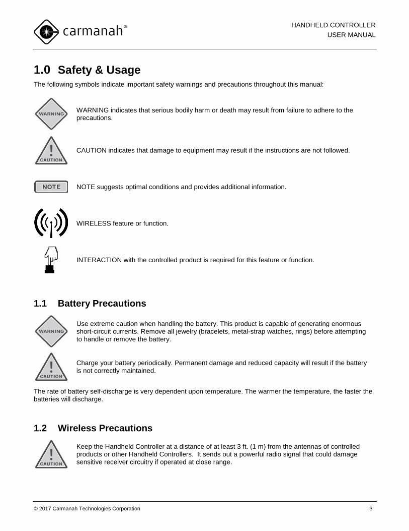
1.0 Safety & Usage The following symbols indicate important safety warnings and precautions throughout this manual:
WARNING indicates that serious bodily harm or death may result from failure to adhere to the precautions.
CAUTION indicates that damage to equipment may result if the instructions are not followed.
NOTE suggests optimal conditions and provides additional information.
WIRELESS feature or function.
INTERACTION with the controlled product is required for this feature or function.
1.1 Battery Precautions
Use extreme caution when handling the battery. This product is capable of generating enormous short-circuit currents. Remove all jewelry (bracelets, metal-strap watches, rings) before attempting to handle or remove the battery.
Charge your battery periodically. Permanent damage and reduced capacity will result if the battery is not correctly maintained.
The rate of battery self-discharge is very dependent upon temperature. The warmer the temperature, the faster the batteries will discharge.
1.2 Wireless Precautions
Keep the Handheld Controller at a distance of at least 3 ft. (1 m) from the antennas of controlled products or other Handheld Controllers. It sends out a powerful radio signal that could damage sensitive receiver circuitry if operated at close range.
HANDHELD CONTROLLER USER MANUAL
© 2017 Carmanah Technologies Corporation 4
1.3 Regulatory This device complies with Part 15 of the FCC Rules. Operation is subject to the following two conditions:
1. This device may not cause harmful interference, and
2. This device must accept any interference received, including interference that may cause undesired operation.
This equipment has been tested and found to comply with the limits for a Class B digital device, pursuant to Part 15 of the FCC Rules. These limits are designed to provide reasonable protection against harmful interference in a residential installation. This equipment generates, uses, and can radiate radio frequency energy and, if not installed and used in accordance with the instruction manual, may cause harmful interference to radio communications; however, there is no guarantee that interference will not occur in a particular installation. If this equipment does cause harmful interference to radio or television reception, which can be determined by turning the equipment off or on, the user is encouraged to try to correct the interference by one or more of the following measures:
• Reorient or relocate the receiving antenna; • Increase the separation between the equipment and receiver; • Connect the equipment into an outlet on a circuit different from that to which the receiver is connected; • Consult the dealer or an experienced radio/TV technician for help.
This Class [B] digital apparatus complies with Canadian ICES-003.
Cet appareil numérique de la classe [B] est conforme à la norme NMB-003 du Canada.
1.4 Warranty Disclaimer
This manual will familiarize you with the features and operating standards of the product. Failure to comply with the use, storage, maintenance, or installation instructions detailed in this manual could void the user warranty.
Changes or modifications not expressly approved by the party responsible for compliance could void the user’s authority to operate the equipment. Installation work must be done by a qualified person(s) in accordance with all application local codes and standards.
HANDHELD CONTROLLER USER MANUAL
© 2017 Carmanah Technologies Corporation 5
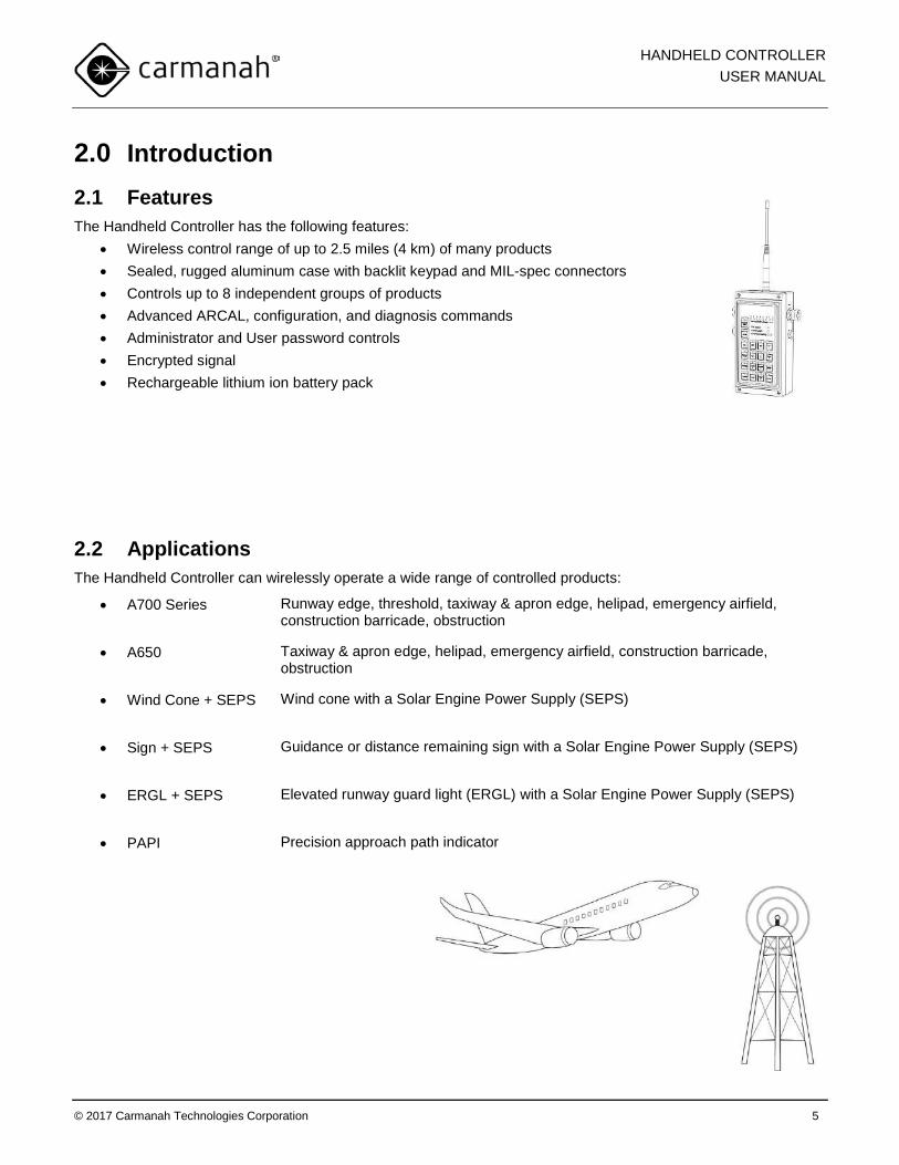
2.0 Introduction 2.1 Features The Handheld Controller has the following features:
• Wireless control range of up to 2.5 miles (4 km) of many products • Sealed, rugged aluminum case with backlit keypad and MIL-spec connectors • Controls up to 8 independent groups of products • Advanced ARCAL, configuration, and diagnosis commands • Administrator and User password controls • Encrypted signal • Rechargeable lithium ion battery pack
2.2 Applications The Handheld Controller can wirelessly operate a wide range of controlled products:
• A700 Series Runway edge, threshold, taxiway & apron edge, helipad, emergency airfield, construction barricade, obstruction
• A650 Taxiway & apron edge, helipad, emergency airfield, construction barricade, obstruction
• Wind Cone + SEPS Wind cone with a Solar Engine Power Supply (SEPS)
• Sign + SEPS Guidance or distance remaining sign with a Solar Engine Power Supply (SEPS)
• ERGL + SEPS Elevated runway guard light (ERGL) with a Solar Engine Power Supply (SEPS)
• PAPI Precision approach path indicator
HANDHELD CONTROLLER USER MANUAL
© 2017 Carmanah Technologies Corporation 6
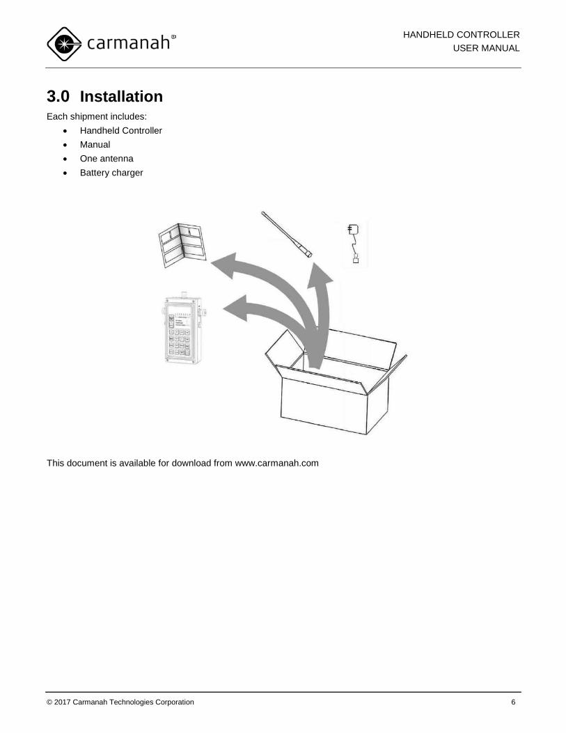
3.0 Installation Each shipment includes:
• Handheld Controller • Manual • One antenna • Battery charger
This document is available for download from www.carmanah.com
HANDHELD CONTROLLER USER MANUAL
© 2017 Carmanah Technologies Corporation 7
3.1 Antenna
Do not operate the Handheld Controller without the antenna fully engaged.
Failure to do so will permanently damage the unit.
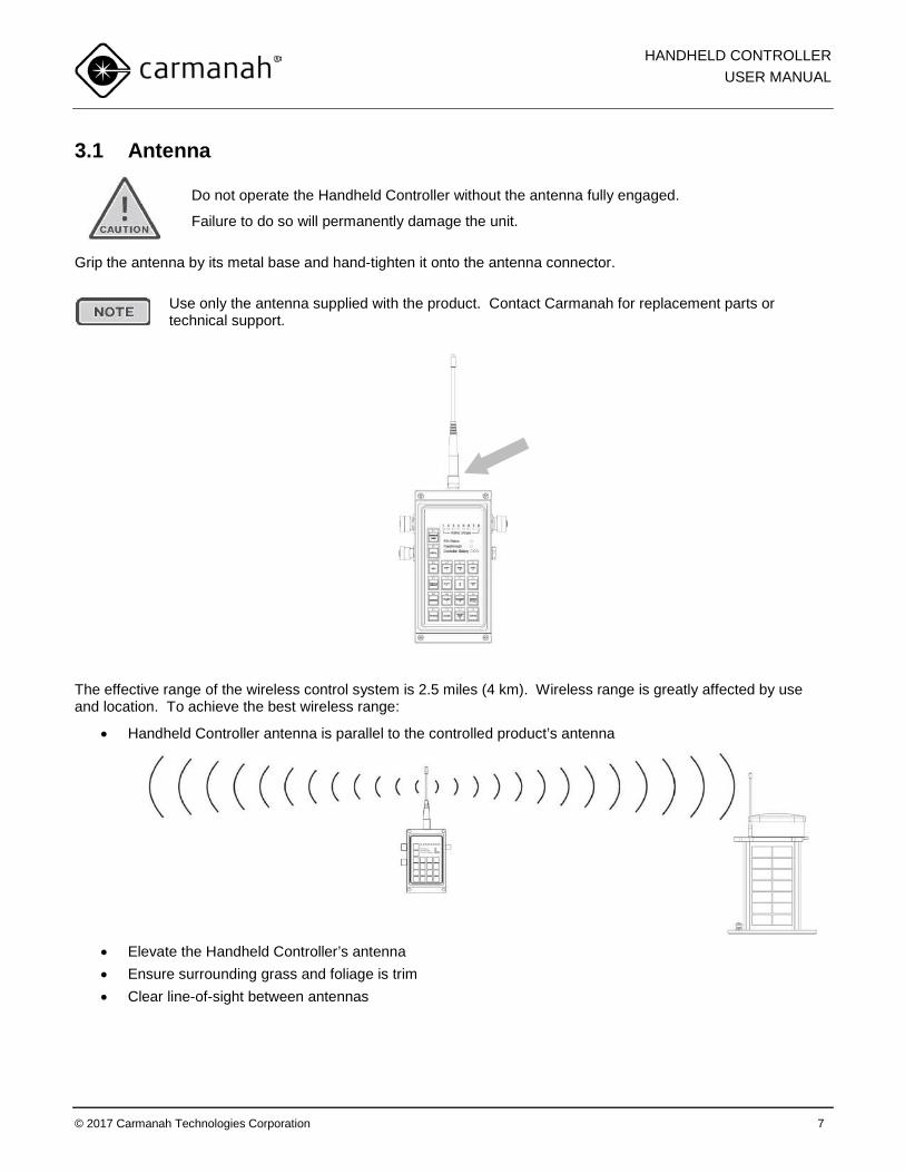
Grip the antenna by its metal base and hand-tighten it onto the antenna connector.
Use only the antenna supplied with the product. Contact Carmanah for replacement parts or technical support.
The effective range of the wireless control system is 2.5 miles (4 km). Wireless range is greatly affected by use and location. To achieve the best wireless range:
• Handheld Controller antenna is parallel to the controlled product’s antenna
• Elevate the Handheld Controller’s antenna • Ensure surrounding grass and foliage is trim • Clear line-of-sight between antennas
HANDHELD CONTROLLER USER MANUAL
© 2017 Carmanah Technologies Corporation 8
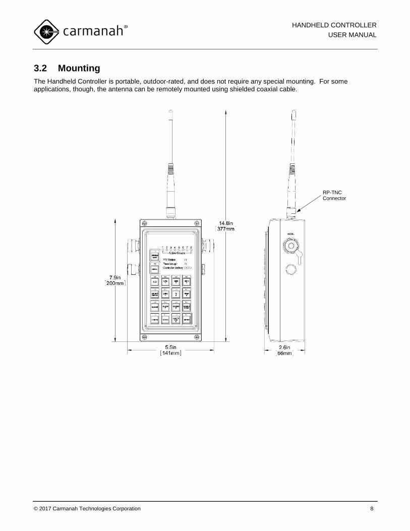
3.2 Mounting The Handheld Controller is portable, outdoor-rated, and does not require any special mounting. For some applications, though, the antenna can be remotely mounted using shielded coaxial cable.
RP-TNC Connector
HANDHELD CONTROLLER USER MANUAL
© 2017 Carmanah Technologies Corporation 9
4.0 Operation 4.1 Theory of Operation The Handheld Controller contains a radio that transmits commands to a receiving radio inside a controlled product. The controlled product operates in one of several modes. The most commonly used are Autonomous and Temporary Modes. For more details on the modes and features specific to a controlled product, see that product’s manual.
4.2 Features
If either the DIAGNOSE or CONFIG buttons are flashing, the controller is waiting for the ENTER button to be pressed to complete the command sequence.
4.2.1 Turning On and Off To turn on the Handheld Controller:
• Press CONTROLLER POWER
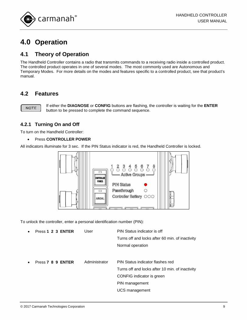
All indicators illuminate for 3 sec. If the PIN Status indicator is red, the Handheld Controller is locked.
To unlock the controller, enter a personal identification number (PIN):
• Press 1 2 3 ENTER User PIN Status indicator is off
Turns off and locks after 60 min. of inactivity
Normal operation
• Press 7 8 9 ENTER Administrator PIN Status indicator flashes red
Turns off and locks after 10 min. of inactivity
CONFIG indicator is green
PIN management
UCS management
HANDHELD CONTROLLER USER MANUAL
© 2017 Carmanah Technologies Corporation 10
ARCAL configuration
The keypad and indicators dim after 30 sec. of inactivity. To restore them:
• Press any key
The Handheld Controller enters standby to conserve power after 1 min. of inactivity. To exit standby:
• Press CONTROLLER POWER
To turn off the controller:
• Press and hold CONTROLLER POWER • Keypad and indicators turn off
To switch between User and Administrator, turn off and on the controller.
4.2.2 Changing PINs (Administrator feature)
User and Administrator PINs must be different.
To change the User PIN:
1. Unlock the controller using the Administrator PIN 2. Press 1 (1 indicator starts flashing) 3. Press ENTER (1 indicator turns on) 4. Enter new PIN using numeric keys (3 – 8 digits in length)
• Active Groups indicators will turn on indicating how many digits have been entered 5. Press ENTER
• ENTER indicator will turn green indicating an acceptable PIN or red indicating the PIN does not have enough digits
6. Re-enter the new PIN a second time to confirm • Active Groups indicators will turn off as the PIN is entered
7. Press ENTER • If both PINs match then the ENTER indicator will briefly turn green • If the PINs do not match, or the PIN is the same as the Administrator PIN, the ENTER indicator will
briefly turn red and you will need to start again To change the Administrator PIN:
1. Unlock the controller using the Administrator PIN 2. Press 2 (2 indicator starts flashing) 3. Press ENTER (2 indicator turns on) 4. Enter new PIN using numeric keys (3 – 8 digits in length)
• Active Group indicators turn on showing how many digits have been entered
HANDHELD CONTROLLER USER MANUAL
© 2017 Carmanah Technologies Corporation 11
5. Press ENTER • ENTER indicator will turn green indicating an acceptable PIN or red indicating the PIN does not
have enough digits 6. Re-enter the new PIN a second time to confirm
• Active Group indicators turn off as the PIN is entered 7. Press ENTER
• If both PINs match then the ENTER indicator will briefly turn green • If the PINs do not match, or the PIN is the same as the User PIN, the ENTER indicator will briefly
turn red and you will need to start again
Using the CLEAR key during Changing PIN:
• If the CLEAR key is pressed and no PIN digits have been entered, the controller will return to Administrator mode with no Administrator operations selected
• If the CLEAR key is pressed and at least one PIN digit has been entered, the controller will return to the start of the Changing PINs operation
4.2.3 Resetting PINs (Administrator feature) This operation will reset the User and Administrator PINs to factory defaults:
1. Unlock the controller using the Administrator PIN 2. Press 3 (3 indicator starts flashing) 3. Press ENTER (3 indicator turns off)
• The ENTER indicator will turn green for a correct operation or red for an incorrect operation
4.2.4 Display The keypad and indicators can be set to different illumination options.
Pressing and holding the CONFIG key cycles through:
1. Dim indicators keypad backlight dark nighttime conditions 2. Dim indicators no keypad backlight 3. Bright indicators no keypad backlight bright daytime conditions
4.2.5 Clear
The CLEAR function only applies to changing PINs (section 4.2.2)
HANDHELD CONTROLLER USER MANUAL
© 2017 Carmanah Technologies Corporation 12
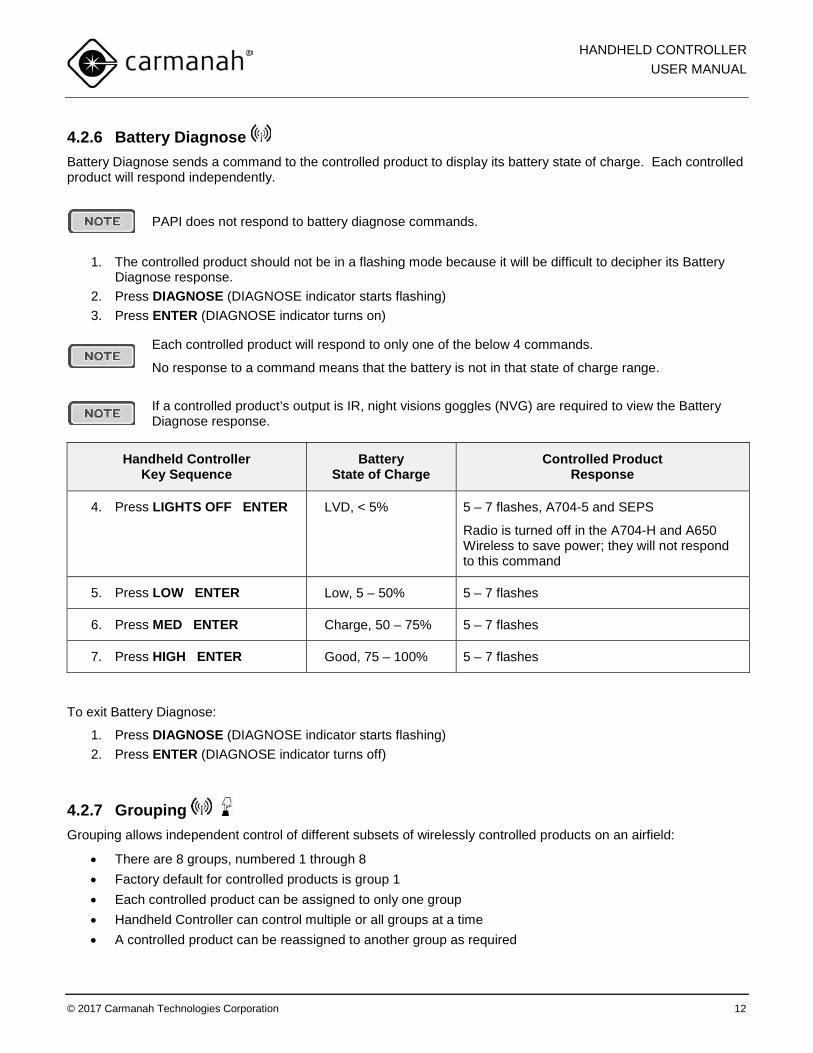
4.2.6 Battery Diagnose Battery Diagnose sends a command to the controlled product to display its battery state of charge. Each controlled product will respond independently.
PAPI does not respond to battery diagnose commands.
1. The controlled product should not be in a flashing mode because it will be difficult to decipher its Battery Diagnose response.
2. Press DIAGNOSE (DIAGNOSE indicator starts flashing) 3. Press ENTER (DIAGNOSE indicator turns on)
Each controlled product will respond to only one of the below 4 commands.
No response to a command means that the battery is not in that state of charge range.
If a controlled product’s output is IR, night visions goggles (NVG) are required to view the Battery Diagnose response.
Handheld Controller Key Sequence
Battery State of Charge
Controlled Product Response
4. Press LIGHTS OFF ENTER LVD, < 5% 5 – 7 flashes, A704-5 and SEPS
Radio is turned off in the A704-H and A650 Wireless to save power; they will not respond to this command
5. Press LOW ENTER Low, 5 – 50% 5 – 7 flashes
6. Press MED ENTER Charge, 50 – 75% 5 – 7 flashes
7. Press HIGH ENTER Good, 75 – 100% 5 – 7 flashes
To exit Battery Diagnose:
1. Press DIAGNOSE (DIAGNOSE indicator starts flashing) 2. Press ENTER (DIAGNOSE indicator turns off)
4.2.7 Grouping Grouping allows independent control of different subsets of wirelessly controlled products on an airfield:
• There are 8 groups, numbered 1 through 8 • Factory default for controlled products is group 1 • Each controlled product can be assigned to only one group • Handheld Controller can control multiple or all groups at a time • A controlled product can be reassigned to another group as required
HANDHELD CONTROLLER USER MANUAL
© 2017 Carmanah Technologies Corporation 13
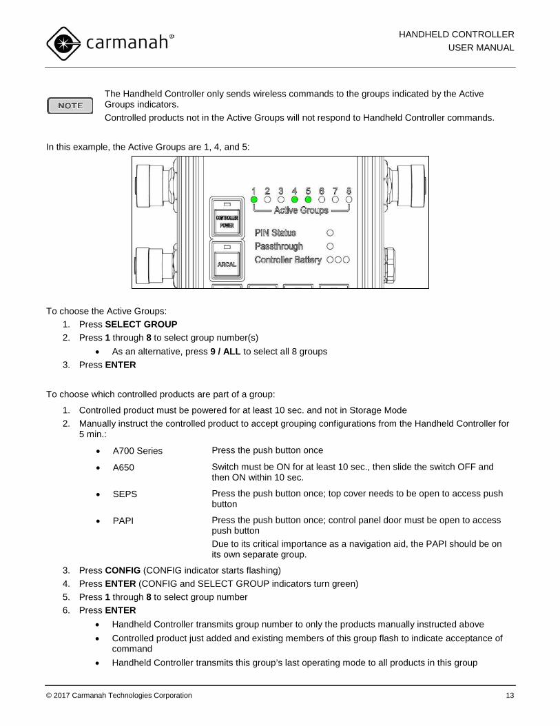
The Handheld Controller only sends wireless commands to the groups indicated by the Active Groups indicators. Controlled products not in the Active Groups will not respond to Handheld Controller commands.
In this example, the Active Groups are 1, 4, and 5:
To choose the Active Groups:
1. Press SELECT GROUP 2. Press 1 through 8 to select group number(s)
• As an alternative, press 9 / ALL to select all 8 groups 3. Press ENTER
To choose which controlled products are part of a group:
1. Controlled product must be powered for at least 10 sec. and not in Storage Mode 2. Manually instruct the controlled product to accept grouping configurations from the Handheld Controller for
5 min.:
• A700 Series Press the push button once
• A650 Switch must be ON for at least 10 sec., then slide the switch OFF and then ON within 10 sec.
• SEPS Press the push button once; top cover needs to be open to access push button
• PAPI Press the push button once; control panel door must be open to access push button Due to its critical importance as a navigation aid, the PAPI should be on its own separate group.
3. Press CONFIG (CONFIG indicator starts flashing) 4. Press ENTER (CONFIG and SELECT GROUP indicators turn green) 5. Press 1 through 8 to select group number 6. Press ENTER
• Handheld Controller transmits group number to only the products manually instructed above • Controlled product just added and existing members of this group flash to indicate acceptance of
command • Handheld Controller transmits this group’s last operating mode to all products in this group
HANDHELD CONTROLLER USER MANUAL
© 2017 Carmanah Technologies Corporation 14
• 5 min. window of accepting grouping configurations is ended for controlled products When you are finished configuring groups, exit CONFIG by:
1. Press CONFIG (CONFIG indicator starts flashing) 2. Press ENTER (CONFIG and SELECT GROUP indicators turn off)
When you add controlled products to a group, products already part of that group are not affected. In this way, you can add to a group as you go without having to re-assign all products in that group.
4.2.8 Unique Code Sequence (Administrator feature) Unique Code Sequence (UCS) allows one or more Handheld Controllers to be uniquely associated to one or more controlled products. When UCS is enabled, the Handheld Controller sends a code with each radio transmission. Only controlled products configured to accept that particular code will respond to the transmission. The benefits are:
Independence Nearby installations of controlled products can be operated independently by different Handheld Controllers without interference.
Security It is not possible for another Handheld Controller to interrupt airfield operation.
Configuring an airfield for UCS involves the following operations:
• Initialization generate an initial UCS in the Handheld Controller and transmit it to non-UCS products • Addition add one or more products to an existing UCS-configured airfield • Re-keying generate a new UCS and transmit it to an older UCS-configured airfield • Removal remove the UCS from the Handheld Controller and controlled products • Reception transmit a UCS from one Handheld Controller to another Handheld Controller
Initialization
The Handheld Controller and controlled products arrive from the factory with UCS removed. To initialize an airfield with a UCS:
1. Unlock the controller using the Administrator PIN 2. Press 7 (7 indicator starts flashing) 3. Press ENTER (7 indicator turns off)
• A new UCS has been generated
The Handheld Controller cannot control UCS configured and non-UCS configured products at the same time.
Only one UCS at a time can be stored by a Handheld Controller or controlled product.
There is no way to retrieve a UCS once it has been removed or replaced with a new UCS. It is recommended that the UCS is transmitted to a backup Handheld Controller.
The new UCS is not saved until it is transmitted to the controlled products.
HANDHELD CONTROLLER USER MANUAL
© 2017 Carmanah Technologies Corporation 15
4. Controlled product must be powered for at least 10 sec. and not in Storage Mode. Manually instruct the controlled product to accept UCS configurations from the Handheld Controller for 5 min.:
• A700 Series Press the push button once
• A650 Switch must be ON for at least 10 sec., then slide the switch OFF and then ON within 10 sec.
• SEPS Press the push button once; top cover needs to be open to access push button
• PAPI Press the push button once; control panel door must be open to access push button
5. Unlock the controller using the Administrator PIN, if it is not already so 6. Press 9 (9 indicator starts flashing) 7. Press ENTER (9 indicator turns on)
• Every time ENTER is pressed, the UCS is transmitted • Each controlled product that receives the UCS will flash 5 – 7 times
8. Press CLEAR to exit this UCS transmission operation
Addition
To add controlled products to an existing UCS-configured airfield:
1. Controlled product must be powered for at least 10 sec. and not in Storage Mode. Manually instruct the controlled product to accept UCS configurations from the Handheld Controller for 5 min.:
• A700 Series Press the push button once
• A650 Switch must be ON for at least 10 sec., then slide the switch OFF and then ON within 10 sec.
• SEPS Press the push button once; top cover needs to be open to access push button
• PAPI Press the push button once; control panel door must be open to access push button
2. Unlock the controller using the Administrator PIN 3. Press 9 (9 indicator starts flashing) 4. Press ENTER (9 indicator turns on)
• Every time ENTER is pressed, the UCS is transmitted • Each controlled product that receives the UCS will flash 5 – 7 times
5. Press CLEAR to exit this UCS transmission operation
This procedure applies to both UCS and non-UCS controlled products.
Products already on this transmitted UCS will flash in response to their UCS being re-transmitted.
Re-keying
Re-keying allows a new UCS to be generated and transmitted to products that are already UCS-configured. To re-key an airfield:
1. Unlock the controller using the Administrator PIN 2. Press 7 (7 indicator starts flashing)
HANDHELD CONTROLLER USER MANUAL
© 2017 Carmanah Technologies Corporation 16
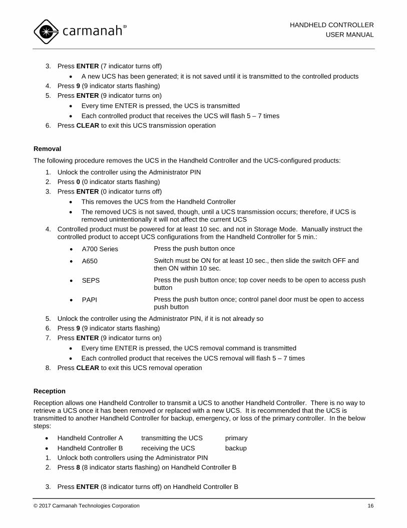
3. Press ENTER (7 indicator turns off) • A new UCS has been generated; it is not saved until it is transmitted to the controlled products
4. Press 9 (9 indicator starts flashing) 5. Press ENTER (9 indicator turns on)
• Every time ENTER is pressed, the UCS is transmitted • Each controlled product that receives the UCS will flash 5 – 7 times
6. Press CLEAR to exit this UCS transmission operation
Removal
The following procedure removes the UCS in the Handheld Controller and the UCS-configured products:
1. Unlock the controller using the Administrator PIN 2. Press 0 (0 indicator starts flashing) 3. Press ENTER (0 indicator turns off)
• This removes the UCS from the Handheld Controller • The removed UCS is not saved, though, until a UCS transmission occurs; therefore, if UCS is
removed unintentionally it will not affect the current UCS 4. Controlled product must be powered for at least 10 sec. and not in Storage Mode. Manually instruct the
controlled product to accept UCS configurations from the Handheld Controller for 5 min.:
• A700 Series Press the push button once
• A650 Switch must be ON for at least 10 sec., then slide the switch OFF and then ON within 10 sec.
• SEPS Press the push button once; top cover needs to be open to access push button
• PAPI Press the push button once; control panel door must be open to access push button
5. Unlock the controller using the Administrator PIN, if it is not already so 6. Press 9 (9 indicator starts flashing) 7. Press ENTER (9 indicator turns on)
• Every time ENTER is pressed, the UCS removal command is transmitted • Each controlled product that receives the UCS removal will flash 5 – 7 times
8. Press CLEAR to exit this UCS removal operation
Reception
Reception allows one Handheld Controller to transmit a UCS to another Handheld Controller. There is no way to retrieve a UCS once it has been removed or replaced with a new UCS. It is recommended that the UCS is transmitted to another Handheld Controller for backup, emergency, or loss of the primary controller. In the below steps:
• Handheld Controller A transmitting the UCS primary • Handheld Controller B receiving the UCS backup 1. Unlock both controllers using the Administrator PIN 2. Press 8 (8 indicator starts flashing) on Handheld Controller B
3. Press ENTER (8 indicator turns off) on Handheld Controller B
HANDHELD CONTROLLER USER MANUAL
© 2017 Carmanah Technologies Corporation 17
• Handheld Controller B is now waiting to receive a UCS transmission from Handheld Controller A 4. Press 9 (9 indicator starts flashing) on Handheld Controller A 5. Press ENTER (9 indicator turns on) on Handheld Controller A
• ENTER indicator briefly turns green on Handheld Controller B to indicate the UCS was received 6. Press CLEAR on Handheld Controller A to exit this UCS transmission operation
Both Handheld Controllers are now programmed with the same UCS and either can be used to control products configured with that same UCS.
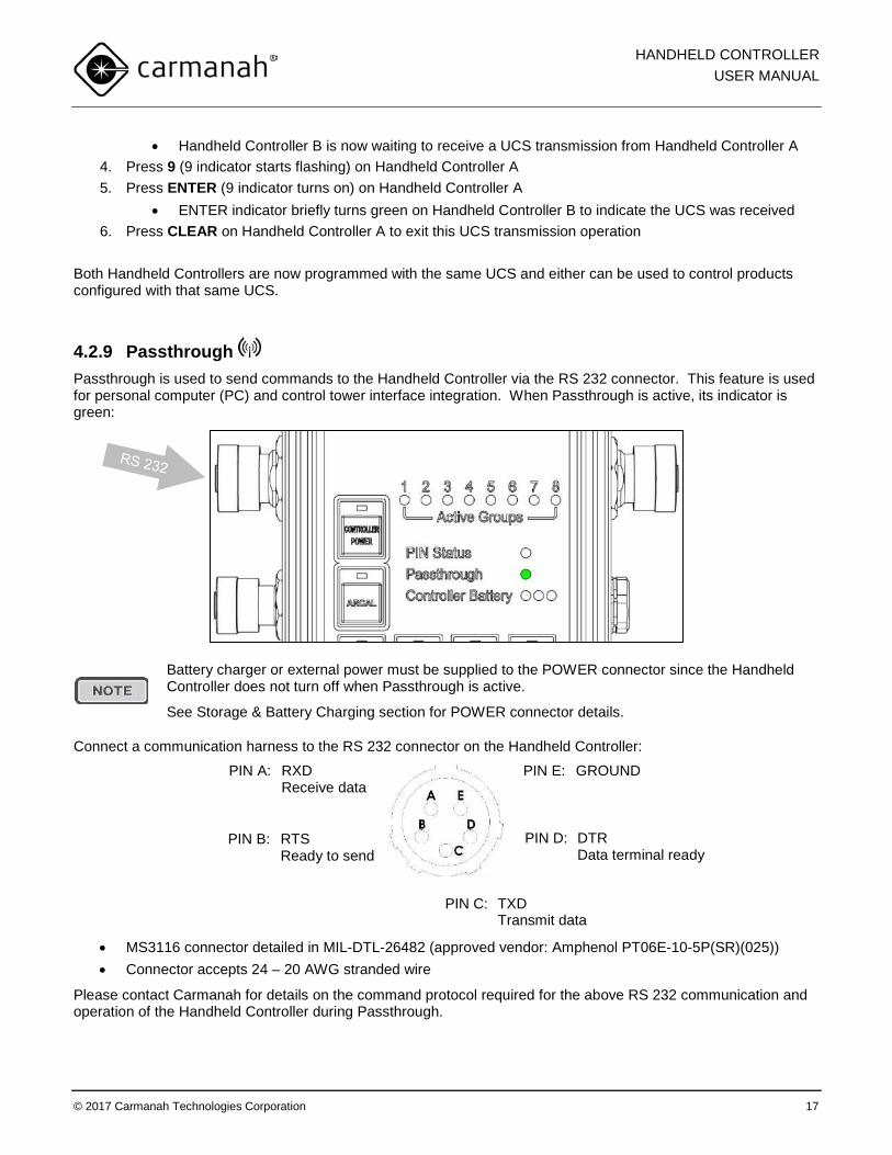
4.2.9 Passthrough Passthrough is used to send commands to the Handheld Controller via the RS 232 connector. This feature is used for personal computer (PC) and control tower interface integration. When Passthrough is active, its indicator is green:
Battery charger or external power must be supplied to the POWER connector since the Handheld Controller does not turn off when Passthrough is active.
See Storage & Battery Charging section for POWER connector details.
Connect a communication harness to the RS 232 connector on the Handheld Controller:
• MS3116 connector detailed in MIL-DTL-26482 (approved vendor: Amphenol PT06E-10-5P(SR)(025)) • Connector accepts 24 – 20 AWG stranded wire
Please contact Carmanah for details on the command protocol required for the above RS 232 communication and operation of the Handheld Controller during Passthrough.
PIN C: TXD Transmit data
PIN B: RTS Ready to send
PIN E: GROUND
PIN D: DTR Data terminal ready
PIN A: RXD Receive data
HANDHELD CONTROLLER USER MANUAL
© 2017 Carmanah Technologies Corporation 18
4.2.10 Factory Reset Factory Reset returns the Handheld Controller to its factory default settings. All PINs are reset, its local UCS is reset, and UCS is then disabled for only the Handheld Controller.
UCS settings are NOT removed from each controlled product.
UCS can be reset/disabled on a controlled product by performing its own factory reset procedure.
To perform a Factory Reset:
1. Press and hold CONTROLLER POWER to turn the Handheld Controller off 2. Press CONTROLLER POWER to turn the Handheld Controller on (PIN Status indicator turns red) 3. Enter the Factory Reset code: 1223334444 4. Press ENTER
• Keypad and indicators turn on and then off indicating a successful Factory Reset
HANDHELD CONTROLLER USER MANUAL
© 2017 Carmanah Technologies Corporation 19
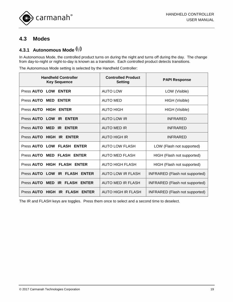
4.3 Modes
4.3.1 Autonomous Mode In Autonomous Mode, the controlled product turns on during the night and turns off during the day. The change from day-to-night or night-to-day is known as a transition. Each controlled product detects transitions.
The Autonomous Mode setting is selected by the Handheld Controller:
Handheld Controller Key Sequence
Controlled Product Setting PAPI Response
Press AUTO LOW ENTER AUTO LOW LOW (Visible)
Press AUTO MED ENTER AUTO MED HIGH (Visible)
Press AUTO HIGH ENTER AUTO HIGH HIGH (Visible)
Press AUTO LOW IR ENTER AUTO LOW IR INFRARED
Press AUTO MED IR ENTER AUTO MED IR INFRARED
Press AUTO HIGH IR ENTER AUTO HIGH IR INFRARED
Press AUTO LOW FLASH ENTER AUTO LOW FLASH LOW (Flash not supported)
Press AUTO MED FLASH ENTER AUTO MED FLASH HIGH (Flash not supported)
Press AUTO HIGH FLASH ENTER AUTO HIGH FLASH HIGH (Flash not supported)
Press AUTO LOW IR FLASH ENTER AUTO LOW IR FLASH INFRARED (Flash not supported)
Press AUTO MED IR FLASH ENTER AUTO MED IR FLASH INFRARED (Flash not supported)
Press AUTO HIGH IR FLASH ENTER AUTO HIGH IR FLASH INFRARED (Flash not supported)
The IR and FLASH keys are toggles. Press them once to select and a second time to deselect.
HANDHELD CONTROLLER USER MANUAL
© 2017 Carmanah Technologies Corporation 20
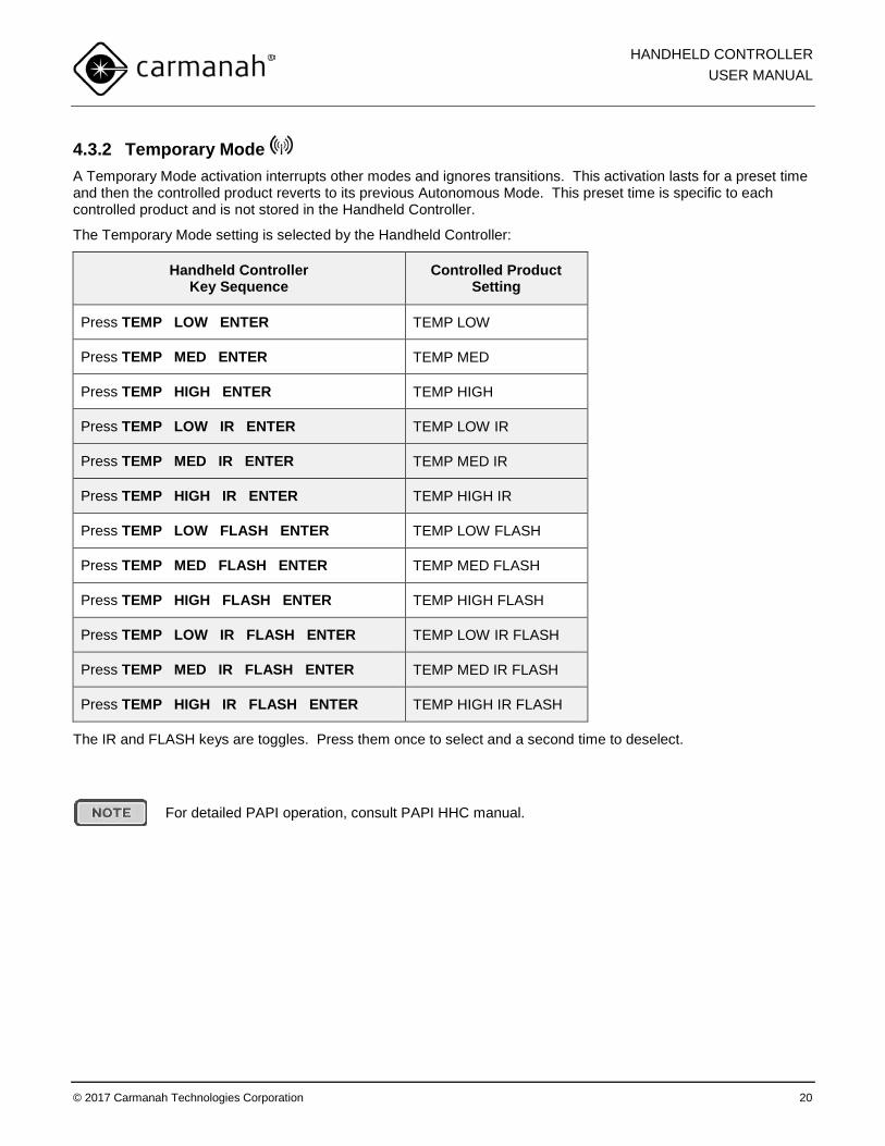
4.3.2 Temporary Mode A Temporary Mode activation interrupts other modes and ignores transitions. This activation lasts for a preset time and then the controlled product reverts to its previous Autonomous Mode. This preset time is specific to each controlled product and is not stored in the Handheld Controller.
The Temporary Mode setting is selected by the Handheld Controller:
Handheld Controller Key Sequence
Controlled Product Setting
Press TEMP LOW ENTER TEMP LOW
Press TEMP MED ENTER TEMP MED
Press TEMP HIGH ENTER TEMP HIGH
Press TEMP LOW IR ENTER TEMP LOW IR
Press TEMP MED IR ENTER TEMP MED IR
Press TEMP HIGH IR ENTER TEMP HIGH IR
Press TEMP LOW FLASH ENTER TEMP LOW FLASH
Press TEMP MED FLASH ENTER TEMP MED FLASH
Press TEMP HIGH FLASH ENTER TEMP HIGH FLASH
Press TEMP LOW IR FLASH ENTER TEMP LOW IR FLASH
Press TEMP MED IR FLASH ENTER TEMP MED IR FLASH
Press TEMP HIGH IR FLASH ENTER TEMP HIGH IR FLASH
The IR and FLASH keys are toggles. Press them once to select and a second time to deselect.
For detailed PAPI operation, consult PAPI HHC manual.
HANDHELD CONTROLLER USER MANUAL
© 2017 Carmanah Technologies Corporation 21
4.3.3 Standby Mode Standby Mode turns off the output of the controlled product and waits for the next day-to-night transition. After this transition, the controlled product enters its previous Autonomous Mode.
1. Press STANDBY 2. Press ENTER
Standby Mode can be interrupted at any time by another Handheld Controller command.
4.3.4 Lights Off Mode Lights Off Mode turns off the output of the controlled product indefinitely until it receives a command to turn its output on.
1. Press LIGHTS OFF 2. Press ENTER
Lights Off Mode can be interrupted at any time by another Handheld Controller command.
4.3.5 Emergency Mode Emergency Mode sets all controlled products in all groups to an emergency flash:
1. Press EMERG 9 / ALL (EMERG 9 / ALL indicator turns on) 2. Press ENTER
Emergency Mode is equivalent to TEMP HIGH FLASH sent to all groups. After the controlled product’s preset Temporary Mode activation time, the controlled products revert to their previous Autonomous Mode. To cancel Emergency Mode before this preset time:
1. Press EMERG 9 / ALL (EMERG 9 / ALL indicator turns off) 2. Press ENTER
HANDHELD CONTROLLER USER MANUAL
© 2017 Carmanah Technologies Corporation 22
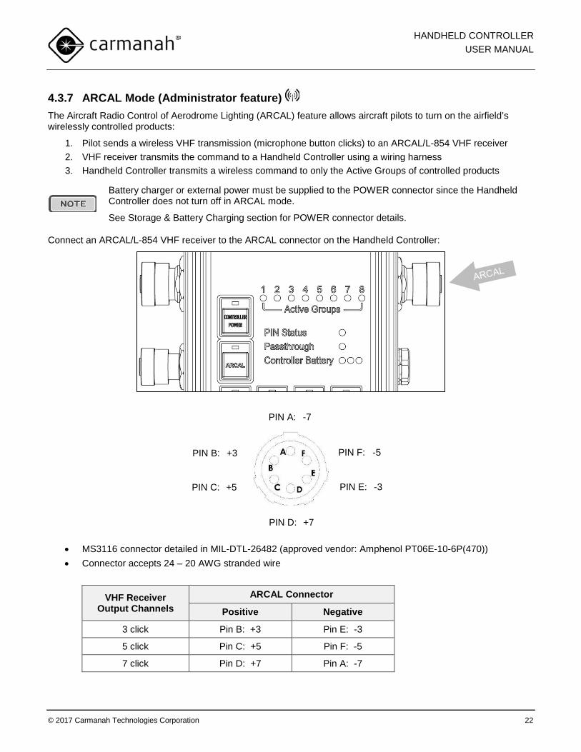
4.3.7 ARCAL Mode (Administrator feature) The Aircraft Radio Control of Aerodrome Lighting (ARCAL) feature allows aircraft pilots to turn on the airfield’s wirelessly controlled products:
1. Pilot sends a wireless VHF transmission (microphone button clicks) to an ARCAL/L-854 VHF receiver 2. VHF receiver transmits the command to a Handheld Controller using a wiring harness 3. Handheld Controller transmits a wireless command to only the Active Groups of controlled products
Battery charger or external power must be supplied to the POWER connector since the Handheld Controller does not turn off in ARCAL mode.
See Storage & Battery Charging section for POWER connector details.
Connect an ARCAL/L-854 VHF receiver to the ARCAL connector on the Handheld Controller:
• MS3116 connector detailed in MIL-DTL-26482 (approved vendor: Amphenol PT06E-10-6P(470)) • Connector accepts 24 – 20 AWG stranded wire
VHF Receiver Output Channels
ARCAL Connector
Positive Negative
3 click Pin B: +3 Pin E: -3
5 click Pin C: +5 Pin F: -5
7 click Pin D: +7 Pin A: -7
PIN A: -7
PIN C: +5
PIN B: +3 PIN F: -5
PIN E: -3
PIN D: +7
HANDHELD CONTROLLER USER MANUAL
© 2017 Carmanah Technologies Corporation 23
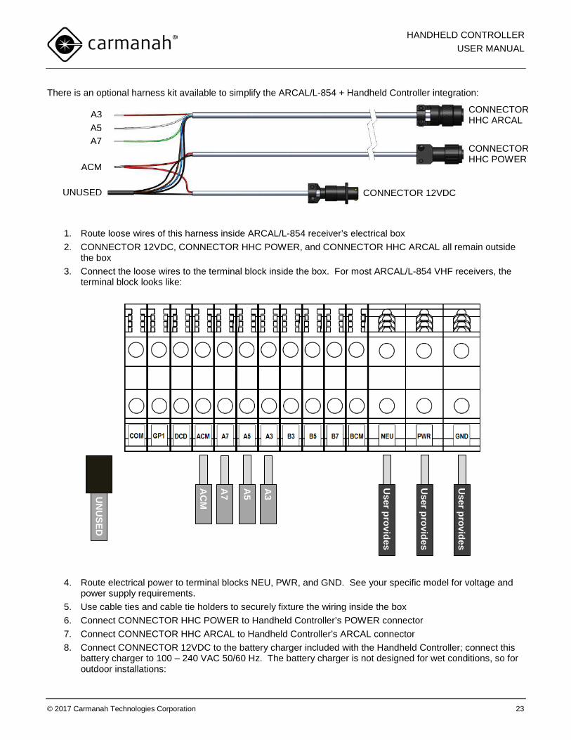
There is an optional harness kit available to simplify the ARCAL/L-854 + Handheld Controller integration:
1. Route loose wires of this harness inside ARCAL/L-854 receiver’s electrical box 2. CONNECTOR 12VDC, CONNECTOR HHC POWER, and CONNECTOR HHC ARCAL all remain outside
the box 3. Connect the loose wires to the terminal block inside the box. For most ARCAL/L-854 VHF receivers, the
terminal block looks like:
4. Route electrical power to terminal blocks NEU, PWR, and GND. See your specific model for voltage and power supply requirements.
5. Use cable ties and cable tie holders to securely fixture the wiring inside the box 6. Connect CONNECTOR HHC POWER to Handheld Controller’s POWER connector 7. Connect CONNECTOR HHC ARCAL to Handheld Controller’s ARCAL connector 8. Connect CONNECTOR 12VDC to the battery charger included with the Handheld Controller; connect this
battery charger to 100 – 240 VAC 50/60 Hz. The battery charger is not designed for wet conditions, so for outdoor installations:
AC
M
A7
A5
A3
User provides
UN
USED
User provides
User provides
CONNECTOR HHC ARCAL A3
A5 A7
ACM
UNUSED
CONNECTOR HHC POWER
CONNECTOR 12VDC
HANDHELD CONTROLLER USER MANUAL
© 2017 Carmanah Technologies Corporation 24
a. Route CONNECTOR HHC POWER and CONNECTOR HHC ARCAL down thru the box’s wiring grommet and out to the Handheld Controller
b. Keep CONNECTOR 12VDC inside the box and connect to battery charger c. Install the entire battery charger inside the box; use cable ties and holders to secure d. Connect the battery charger to 100 – 240 VAC 50/60 Hz via outdoor-rated cabling
Please contact Carmanah for details on the wiring connection to your specific ARCAL/L-854 VHF receiver.
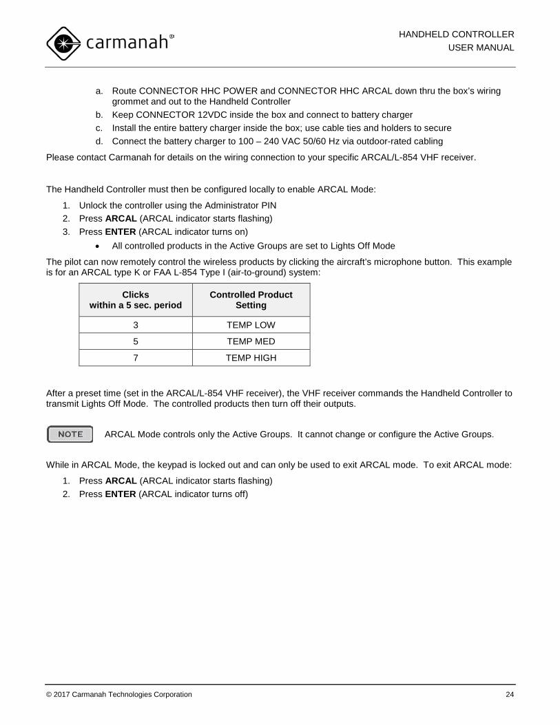
The Handheld Controller must then be configured locally to enable ARCAL Mode:
1. Unlock the controller using the Administrator PIN 2. Press ARCAL (ARCAL indicator starts flashing) 3. Press ENTER (ARCAL indicator turns on)
• All controlled products in the Active Groups are set to Lights Off Mode
The pilot can now remotely control the wireless products by clicking the aircraft’s microphone button. This example is for an ARCAL type K or FAA L-854 Type I (air-to-ground) system:
Clicks within a 5 sec. period
Controlled Product Setting
3 TEMP LOW
5 TEMP MED
7 TEMP HIGH
After a preset time (set in the ARCAL/L-854 VHF receiver), the VHF receiver commands the Handheld Controller to transmit Lights Off Mode. The controlled products then turn off their outputs.
ARCAL Mode controls only the Active Groups. It cannot change or configure the Active Groups.
While in ARCAL Mode, the keypad is locked out and can only be used to exit ARCAL mode. To exit ARCAL mode:
1. Press ARCAL (ARCAL indicator starts flashing) 2. Press ENTER (ARCAL indicator turns off)
HANDHELD CONTROLLER USER MANUAL
© 2017 Carmanah Technologies Corporation 25
5.0 Maintenance 5.1 Storage & Battery Charging When storing the Handheld Controller, it is important to maintain the battery:
• Press and hold CONTROLLER POWER to turn off • Store in a cool location • Periodically charge the battery
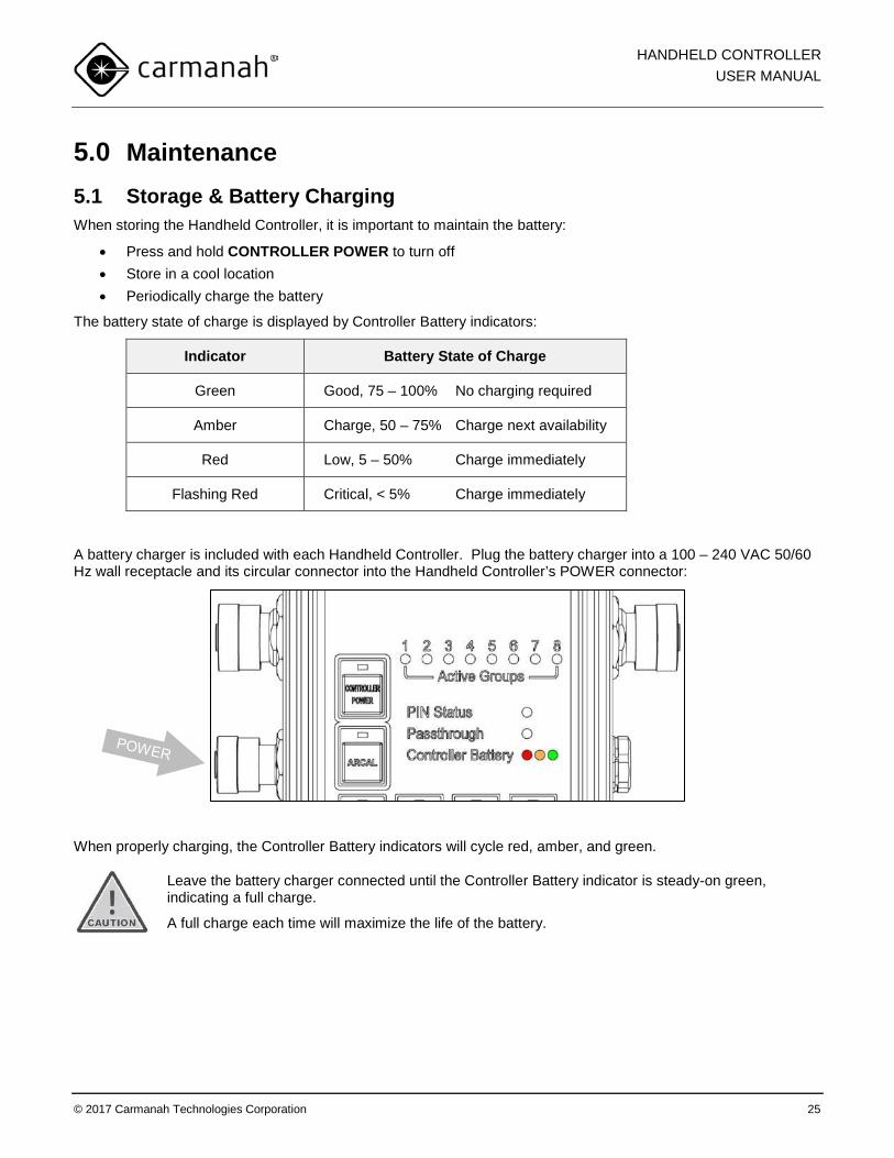
The battery state of charge is displayed by Controller Battery indicators:
Indicator Battery State of Charge
Green Good, 75 – 100% No charging required
Amber Charge, 50 – 75% Charge next availability
Red Low, 5 – 50% Charge immediately
Flashing Red Critical, < 5% Charge immediately
A battery charger is included with each Handheld Controller. Plug the battery charger into a 100 – 240 VAC 50/60 Hz wall receptacle and its circular connector into the Handheld Controller’s POWER connector:
When properly charging, the Controller Battery indicators will cycle red, amber, and green.
Leave the battery charger connected until the Controller Battery indicator is steady-on green, indicating a full charge.
A full charge each time will maximize the life of the battery.
HANDHELD CONTROLLER USER MANUAL
© 2017 Carmanah Technologies Corporation 26
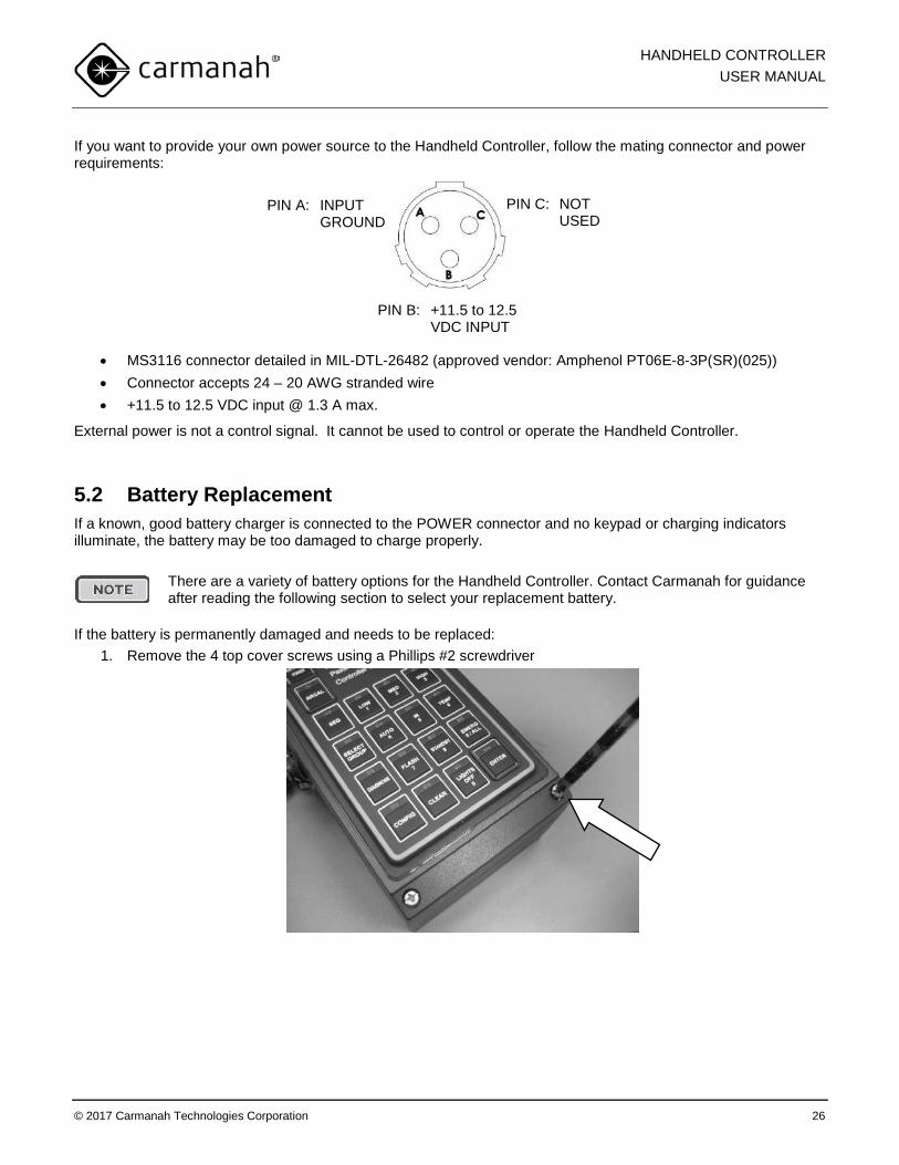
If you want to provide your own power source to the Handheld Controller, follow the mating connector and power requirements:
• MS3116 connector detailed in MIL-DTL-26482 (approved vendor: Amphenol PT06E-8-3P(SR)(025)) • Connector accepts 24 – 20 AWG stranded wire • +11.5 to 12.5 VDC input @ 1.3 A max.
External power is not a control signal. It cannot be used to control or operate the Handheld Controller.
5.2 Battery Replacement If a known, good battery charger is connected to the POWER connector and no keypad or charging indicators illuminate, the battery may be too damaged to charge properly.
There are a variety of battery options for the Handheld Controller. Contact Carmanah for guidance after reading the following section to select your replacement battery.
If the battery is permanently damaged and needs to be replaced: 1. Remove the 4 top cover screws using a Phillips #2 screwdriver
PIN A: INPUT GROUND
PIN C: NOT USED
PIN B: +11.5 to 12.5 VDC INPUT
HANDHELD CONTROLLER USER MANUAL
© 2017 Carmanah Technologies Corporation 27
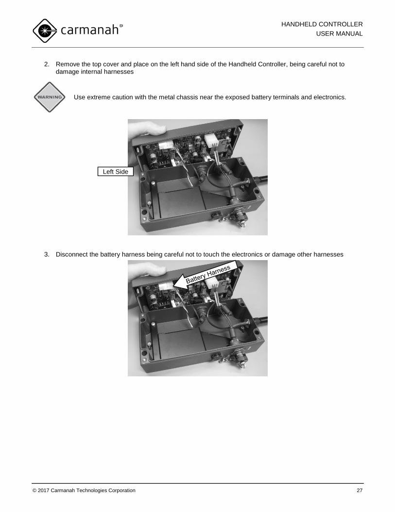
2. Remove the top cover and place on the left hand side of the Handheld Controller, being careful not to damage internal harnesses
Use extreme caution with the metal chassis near the exposed battery terminals and electronics.
3. Disconnect the battery harness being careful not to touch the electronics or damage other harnesses
Left Side
HANDHELD CONTROLLER USER MANUAL
© 2017 Carmanah Technologies Corporation 28
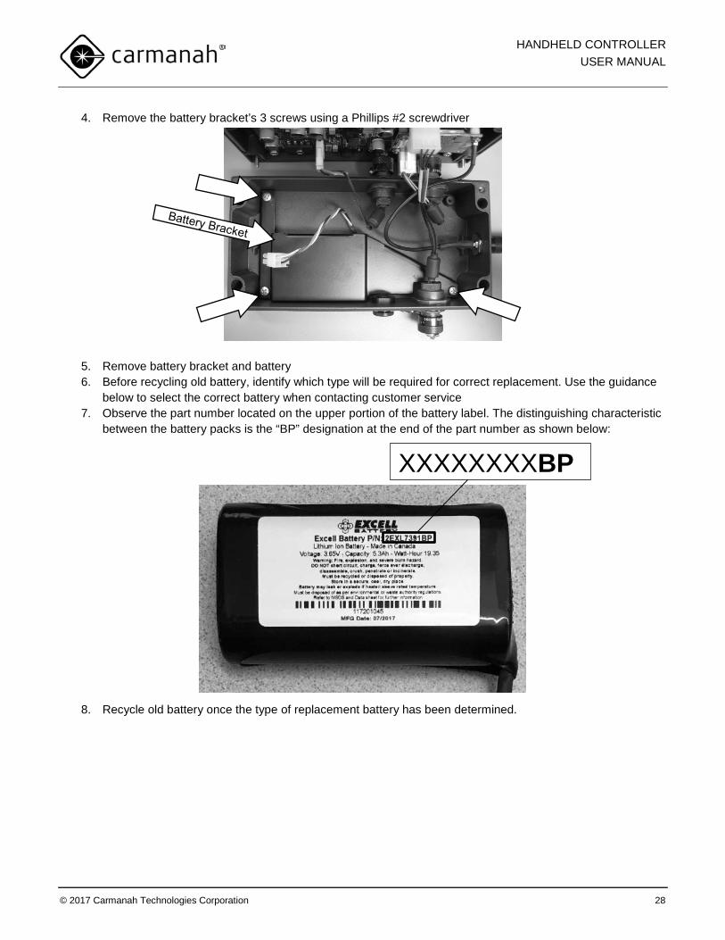
4. Remove the battery bracket’s 3 screws using a Phillips #2 screwdriver
5. Remove battery bracket and battery 6. Before recycling old battery, identify which type will be required for correct replacement. Use the guidance
below to select the correct battery when contacting customer service 7. Observe the part number located on the upper portion of the battery label. The distinguishing characteristic
between the battery packs is the “BP” designation at the end of the part number as shown below:
8. Recycle old battery once the type of replacement battery has been determined.
XXXXXXXXBP
HANDHELD CONTROLLER USER MANUAL
© 2017 Carmanah Technologies Corporation 29
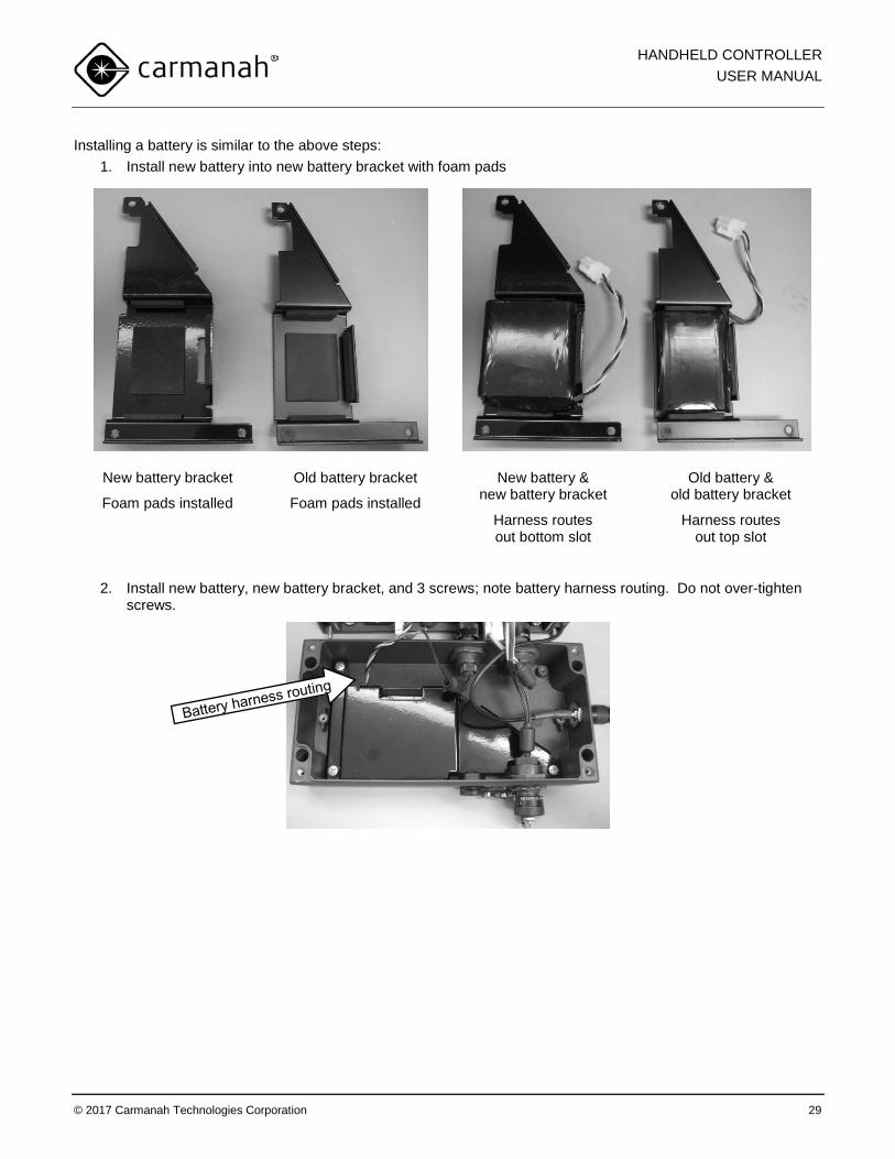
Installing a battery is similar to the above steps: 1. Install new battery into new battery bracket with foam pads
New battery bracket
Foam pads installed
Old battery bracket
Foam pads installed
New battery & new battery bracket
Harness routes out bottom slot
Old battery & old battery bracket
Harness routes out top slot
2. Install new battery, new battery bracket, and 3 screws; note battery harness routing. Do not over-tighten
screws.
HANDHELD CONTROLLER USER MANUAL
© 2017 Carmanah Technologies Corporation 30
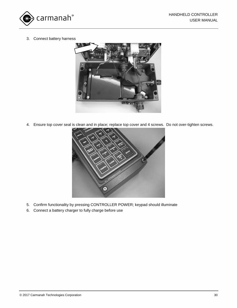
3. Connect battery harness
4. Ensure top cover seal is clean and in place; replace top cover and 4 screws. Do not over-tighten screws.
5. Confirm functionality by pressing CONTROLLER POWER; keypad should illuminate 6. Connect a battery charger to fully charge before use

HANDHELD CONTROLLER USER MANUAL
© 2017 Carmanah Technologies Corporation 31
5.3 Recycling This product required the extraction and use of natural resources. It may contain substances that could be harmful to the environment or human health if improperly handled at the product’s end of life. In order to avoid release of such substances into the environment and to reduce the use of natural resources, we encourage you to recycle the product in an appropriate way that will ensure most of the materials are reused or recycled appropriately. Check your local municipality for electronics recyclers.
The symbol indicates that this product complies with the European Union’s requirements according to Directive 2002/96/EC on waste electrical and electronic equipment (WEEE).
The battery is a rechargeable lithium ion battery. Consult your local laws for information on recycling.
HANDHELD CONTROLLER USER MANUAL
© 2017 Carmanah Technologies Corporation 32
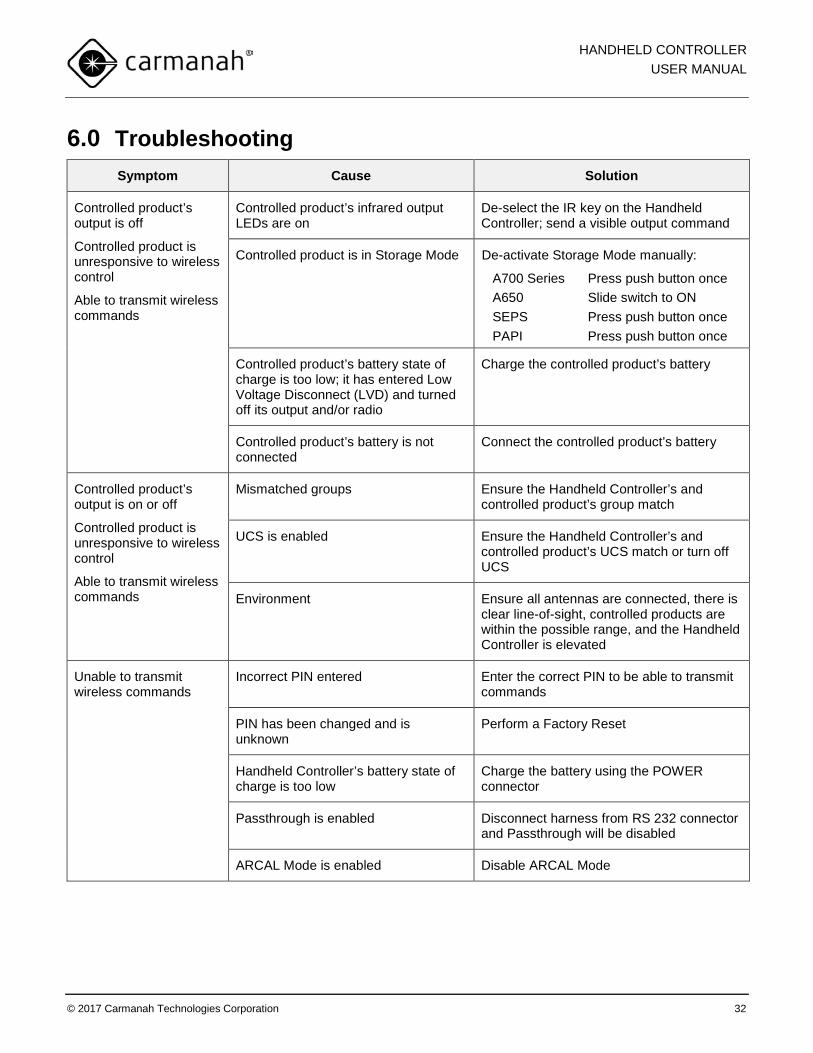
6.0 Troubleshooting Symptom Cause Solution
Controlled product’s output is off
Controlled product is unresponsive to wireless control
Able to transmit wireless commands
Controlled product’s infrared output LEDs are on
De-select the IR key on the Handheld Controller; send a visible output command
Controlled product is in Storage Mode De-activate Storage Mode manually:
A700 Series Press push button once A650 Slide switch to ON SEPS Press push button once PAPI Press push button once
Controlled product’s battery state of charge is too low; it has entered Low Voltage Disconnect (LVD) and turned off its output and/or radio
Charge the controlled product’s battery
Controlled product’s battery is not connected
Connect the controlled product’s battery
Controlled product’s output is on or off
Controlled product is unresponsive to wireless control
Able to transmit wireless commands
Mismatched groups Ensure the Handheld Controller’s and controlled product’s group match
UCS is enabled Ensure the Handheld Controller’s and controlled product’s UCS match or turn off UCS
Environment Ensure all antennas are connected, there is clear line-of-sight, controlled products are within the possible range, and the Handheld Controller is elevated
Unable to transmit wireless commands
Incorrect PIN entered Enter the correct PIN to be able to transmit commands
PIN has been changed and is unknown
Perform a Factory Reset
Handheld Controller’s battery state of charge is too low
Charge the battery using the POWER connector
Passthrough is enabled Disconnect harness from RS 232 connector and Passthrough will be disabled
ARCAL Mode is enabled Disable ARCAL Mode

HANDHELD CONTROLLER USER MANUAL
© 2017 Carmanah Technologies Corporation 33
7.0 Warranty This product is covered by the Carmanah warranty. Visit www.carmanah.com for additional information or to register your product online.
Before contacting Carmanah’s customer service department, please have the serial number of your product available, a brief description of the problem, as well as all details of the installation and recharging efforts.
To contact Customer Service:
Mail: Carmanah Technologies Corp. 250 Bay Street Victoria, BC Canada V9A 3K5
Phone: +1.250.380.0052 (worldwide) 1.877.722.8877 (toll-free, U.S. and Canada)
Fax: 1.250.380.0062
Email: [email protected]
Website: carmanah.com

HANDHELD CONTROLLER USER MANUAL
© 2017 Carmanah Technologies Corporation 34
8.0 Appendices 8.1 Glossary
AC Alternating Current
ACGIH American Conference of Governmental and Industrial Hygienists
ARCAL Aircraft Radio Control of Aerodrome Lighting
DC Direct Current
EMS Energy Management System
FAA Federal Aviation Administration
FCC Federal Communications Commission
ICAO International Civil Aviation Organization
ICES Industry Canada Equipment Standard
IR Infrared
ISM Industrial, Scientific and Medical
LED Light Emitting Diode
LVD Low Voltage Disconnect
NVG Night Vision Goggle
RoHS Restriction on Hazardous Substances
UCS Unique Code Sequence
WEEE Waste Electrical and Electronic Equipment
HANDHELD CONTROLLER USER MANUAL
© 2017 Carmanah Technologies Corporation 35
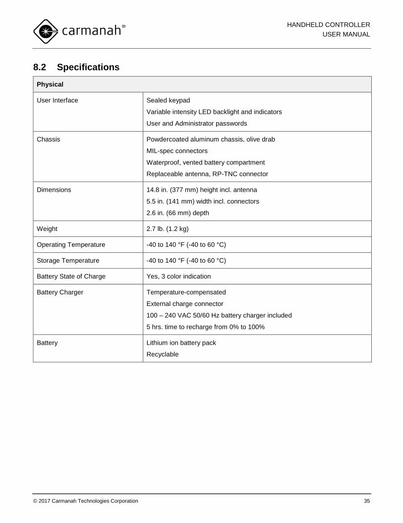
8.2 Specifications
Physical
User Interface Sealed keypad
Variable intensity LED backlight and indicators
User and Administrator passwords
Chassis Powdercoated aluminum chassis, olive drab
MIL-spec connectors
Waterproof, vented battery compartment
Replaceable antenna, RP-TNC connector
Dimensions 14.8 in. (377 mm) height incl. antenna
5.5 in. (141 mm) width incl. connectors
2.6 in. (66 mm) depth
Weight 2.7 lb. (1.2 kg)
Operating Temperature -40 to 140 °F (-40 to 60 °C)
Storage Temperature -40 to 140 °F (-40 to 60 °C)
Battery State of Charge Yes, 3 color indication
Battery Charger Temperature-compensated
External charge connector
100 – 240 VAC 50/60 Hz battery charger included
5 hrs. time to recharge from 0% to 100%
Battery Lithium ion battery pack
Recyclable
HANDHELD CONTROLLER USER MANUAL
© 2017 Carmanah Technologies Corporation 36
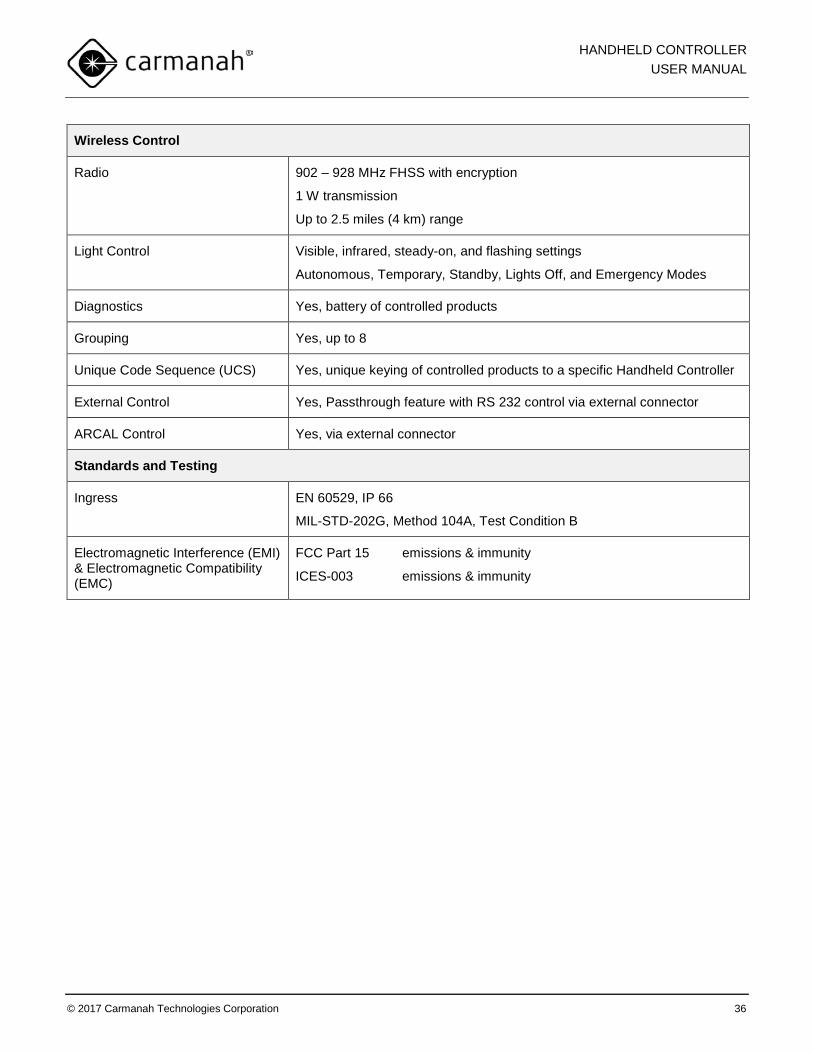
Wireless Control
Radio 902 – 928 MHz FHSS with encryption
1 W transmission
Up to 2.5 miles (4 km) range
Light Control Visible, infrared, steady-on, and flashing settings
Autonomous, Temporary, Standby, Lights Off, and Emergency Modes
Diagnostics Yes, battery of controlled products
Grouping Yes, up to 8
Unique Code Sequence (UCS) Yes, unique keying of controlled products to a specific Handheld Controller
External Control Yes, Passthrough feature with RS 232 control via external connector
ARCAL Control Yes, via external connector
Standards and Testing
Ingress EN 60529, IP 66
MIL-STD-202G, Method 104A, Test Condition B
Electromagnetic Interference (EMI) & Electromagnetic Compatibility (EMC)
FCC Part 15 emissions & immunity
ICES-003 emissions & immunity
© 2017 Carmanah Technologies Corporation 47125_HandheldController_UserManual_RevD
© 2017 Carmanah Technologies Corporation
Technical Support: Email: [email protected] Toll Free: 1.877.722.8877 (US & Canada) Worldwide: 1.250.380.0052 Fax: 1.250.380.0062 Web: carmanah.com