Embed Size (px)
Citation preview

HAMMAGThe first free & monthly Emagazine for amateurradio, SWL...
NUMBER 8 September 2009ISSN : 17606470 http://www.hammag.com
TThhee TTssuunnaammii AAmmppll ii ff iieerr
TThhee 44xx44 ssll iimmtteennnnaa
PPoowweerr SSoouurrccee

The HamMag Hall of fame................................................................ 34X4 Slimtenna By 4X4LH............................................ 4DB2TAM MUSEUM By G8DET.................................. 10The Tsunami Amplifier By DF5XV............................. 11The DXnews from the Web.................................... 20The DX Calendar By SM3CVM............................ 23Alternate Power Source By KD9KC...................... 28Keep Track WSJT QSOs By SM6NZV.................... 30Mongolian DX contest By JT1CD......................... 31Comic's HAM............................................................ 32
Thanks to : 4X4LH, DF5XV, F4FIS, G8DET, JT1CD, K3IXD, KD9KC, SM3CVM,SM6NZV, VE3SKPThanks also to the OM's who believe in this magazine, to all the donators andOM's who sent helpful messages.
You can contact us by EMail : postmaster@hammag.comOur websites :http://www.hammag.com (English)http://www.hammag.fr (French) ISSN N.17606470

TThhee Hall of FameDonators of AUGUST
NQ9A, CarolynN8SHZ, BelaRichard VuillequezTony HumphrisOM3AG, LadislavW9BF, Robert
Thanks a lot for your support !To live HAMMAG needs you.Any help is welcome.Send us articles, informations.Send your articles to :[email protected]
http://www.hammag.com

A Reprint by Courtesy of antenneX Online Magazine issue Number: 119http://www.antennex.com
Some of us prefer to spend a lot of money on towers, enormous in height and price, with lotsof elements antennas and on top of it using the highest legal power. The rest of us, that haveto deduct hard earned money from the family budget, have to make some delving in theintricacies of efficient transmitting, propagation problems and its many ingredients, if we wantto still enjoy our hobby. It seems that today’s Hi tech brought the hobby to a discouraging state we don’t build receivers and transmitters any more and on the operating side of it – anendless chasing of dx for a report and a QSL, which doesn’t seem to be the highest goal ofour hobby.What is left to us is indeed, directing our efforts in better understanding the proper use ofantennas, evaluating their radiation efficiency, getting to know the fouling behavior of theionosphere, along with better differentiating between dBi, dBd, dB, etc. and even find out whatRadiation resistance is.After long years of thorough combing the literature, internet and other sources of information,along with building and using many different antennas, I came to the conclusion that one ofthe best ways to reach efficiently a distant station for a QSO of not less than 1020 minutes, isthe use of vertical antennas with no more than 150200 watts.In spite of some “great sages” saying that “a vertical antenna transmits equally bad to alldirections”, my present “antenna of the house” is a pileup busting full wavelength wire DeltaLoop, vertically polarized. I realized that the 1/4 wavelength ground plane antenna and the 5/8wl antenna needing a good "mirror" underneath, are good choice on top of a car’s metal roof,but will put you in jeopardy with your wife’s garden and the lawn mower, if you try to bringthem into your home station for HF.I also realized that although a three or four elements Yagi beam concentrates its power in anarrow horizontal pattern, its vertical “take off ” suffers from a high radiation angle of ~30°,loosing a lot of dB’s in excessive number of hops to the ionosphere, while a good verticalmonobander reaches the dx with less hops, with almost the same strength!I further discovered that following the request of amateurs looking for a single knob (main’son/off) “no tuning” transceiver, made the manufacturers provide rather compact transceiversbut without any way of antenna tuning and loading. Instead promoting an external ATU to beadded to the paraphernalia of the station with, of course, additional expenditure. It happensalso because of the wish of amateurs and in many cases their necessity to use one singleantenna for as many bands as possible no matter how bad the transmission is. Here lays oneof the misunderstandings of many members of our fraternity. When feeding a dipole with itsbasic frequency it was built for, we get its basic well known clean pattern. Using the samedipole length on other frequencies with an ATU as a mediator, correcting wrong impedance,reactance and SWR for the tx to be happy, BUT:
The 4X4 SlimtennaBy Eli Kovo 4X4LH

1) The antenna will not provide the length the wave is looking for, according the rules ofPhysics.2) The clean basic pattern of the dipole is distorted into many additional lobes on account ofthe main lobe.3) The low take off angle desired for dx is elevated (to warm the clouds), causing morehops on its long way to the dx station.4) The radiation efficiency becomes so low that out of our 150 watts only 15 poor watts get outon the air.5) The ionosphere, acting as a mirror, absorbs some of our signal as a “payment for itsservices”, swallowing 810dB (for each hop) of our miserable signal, arriving at the dx stationwith less then 1 watt.A correctly transmitting antenna is the best “amplifier” I know. A 3 dB gain doubles the powerof your signal and a 6 dB quadruples it. Your 150 watts are sent out as 300 watts! Add theequivalent gain of low take off angle transmission (less hops) and you are better off than akilowatt!!I brought this long preface for my hobby fellows, pointing out some of the pitfalls. If we getaware of them we will benefit by better understanding of the how’s and why’s of antennas andenhance our station performance. This will hopefully encourage us to build and use simple,cheap and efficient, low take off angle monoband verticals.Here comes my modification of the Slim Jim antenna which I call “The 4X4 Slimtenna”.
The esteemed Slim Jim antenna was invented by Fred Judd G2BCX on the basis of the JPole antenna, which was based on the German Zepelin antenna. This one was an endfeddipole, fed by a 1/4 wavelength open wire ladder section, hanging out beneath the big airship.It was actually invented by an Austrian engineer in 1908 intended for use in balloons in asuspended mode. Niels Rudberg OZ8NJ found this astounding fact in an old textbookpublished quickly in the same year by Dr. J. Zenneck – Professor of Physics in Muenich(RadCom June 2006).Pic1 The Zepp and J Pole, the development of the Slim Jim and its upgrade for HF
“The 4X4 Slimtenna”

Both J Pole and the Slim Jim inventors kept its ¼ wavelength matching section in line with the½ wavelength long antenna, e.g. a half wavelength plus another quarter wavelength. Beneatha balloon or a dirigible this was a fine and suitable arrangement as the antenna and thematching feeder were rolled out at lift off from a drum and rolled back when landing. It iscertainly difficult for the ham to cope with these enormous lengths if he wants to use it as avertical aerial on the HF bands. This is probably the reason why these fine antennas wereconfined mainly to VHF.This type of feed can be in line with an endfed antenna or can be bent 90° to it. Both J Poleand Slim Jim can be put up vertically for HF easier, if the feeding section lays near theground or the roof. I will refrain discussing the J Pole as it doesn’t offer more than an endfedhalfwave dipole.On the other hand, the Slim Jim is one of the very good antennas offering a good radiationefficiency having:a) A driven element that combines the "efforts" of two halfwaves in phase, in a ratherrestricted space with about 3 dBd gain and an unbelievable 8° take off firing angle towardsthe horizon almost parallel to ground!b) Its overall height is no more than half wavelength.c) No need at all for (repulsive quantity of) radials to substitute a missing length for our waveto ride on (unlike the ¼ wavelength ground plane searching underneath for its "lost" other 1/4length, lifting its lobe up to Heaven for help… A pitifulscene).Although building verticals for HF is easiest for 10 meterband, we will plunge into building it for 20 meters bandand find out it isn’t out of the reach of the ham bothfinancially and mechanically. (See pic. 2)
Pic 3: The omega clamps and a flange at 4X4LH’s roof
Pic.2: An overall and detailed view of the components included in the 4X4 Slimtenna
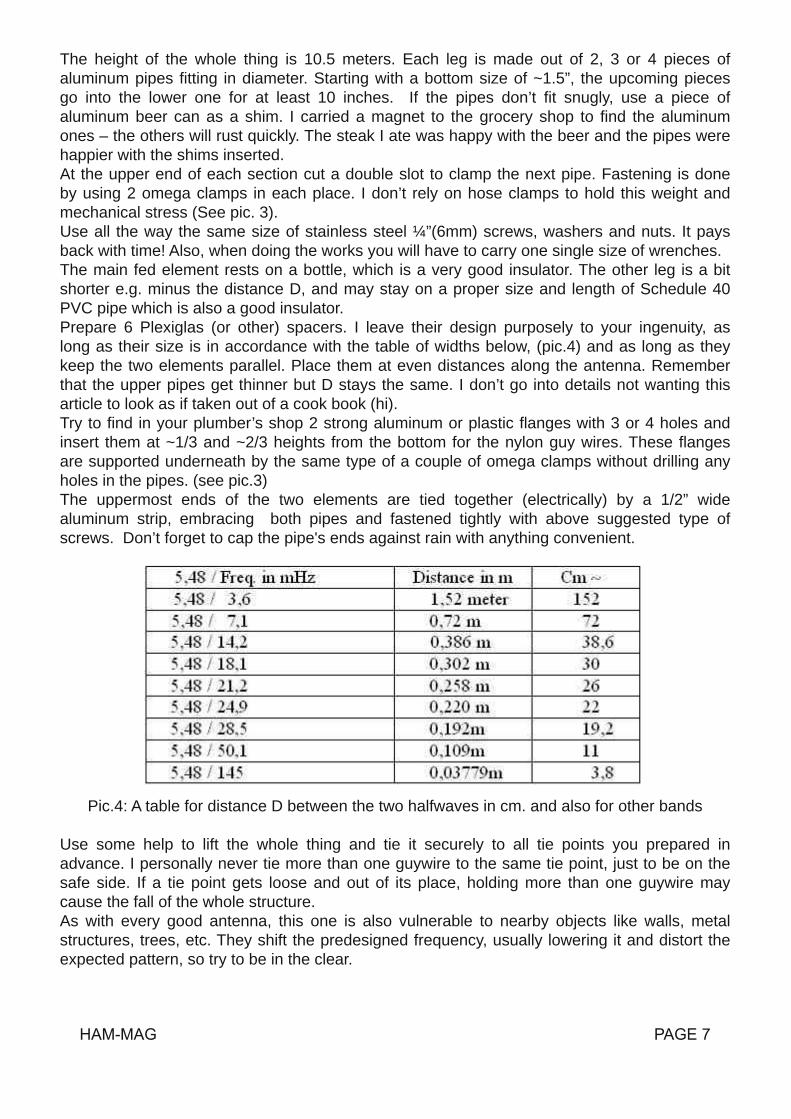
The height of the whole thing is 10.5 meters. Each leg is made out of 2, 3 or 4 pieces ofaluminum pipes fitting in diameter. Starting with a bottom size of ~1.5”, the upcoming piecesgo into the lower one for at least 10 inches. If the pipes don’t fit snugly, use a piece ofaluminum beer can as a shim. I carried a magnet to the grocery shop to find the aluminumones – the others will rust quickly. The steak I ate was happy with the beer and the pipes werehappier with the shims inserted.At the upper end of each section cut a double slot to clamp the next pipe. Fastening is doneby using 2 omega clamps in each place. I don’t rely on hose clamps to hold this weight andmechanical stress (See pic. 3).Use all the way the same size of stainless steel ¼”(6mm) screws, washers and nuts. It paysback with time! Also, when doing the works you will have to carry one single size of wrenches.The main fed element rests on a bottle, which is a very good insulator. The other leg is a bitshorter e.g. minus the distance D, and may stay on a proper size and length of Schedule 40PVC pipe which is also a good insulator.Prepare 6 Plexiglas (or other) spacers. I leave their design purposely to your ingenuity, aslong as their size is in accordance with the table of widths below, (pic.4) and as long as theykeep the two elements parallel. Place them at even distances along the antenna. Rememberthat the upper pipes get thinner but D stays the same. I don’t go into details not wanting thisarticle to look as if taken out of a cook book (hi).Try to find in your plumber’s shop 2 strong aluminum or plastic flanges with 3 or 4 holes andinsert them at ~1/3 and ~2/3 heights from the bottom for the nylon guy wires. These flangesare supported underneath by the same type of a couple of omega clamps without drilling anyholes in the pipes. (see pic.3)The uppermost ends of the two elements are tied together (electrically) by a 1/2” widealuminum strip, embracing both pipes and fastened tightly with above suggested type ofscrews. Don’t forget to cap the pipe's ends against rain with anything convenient.
Pic.4: A table for distance D between the two halfwaves in cm. and also for other bandsUse some help to lift the whole thing and tie it securely to all tie points you prepared inadvance. I personally never tie more than one guywire to the same tie point, just to be on thesafe side. If a tie point gets loose and out of its place, holding more than one guywire maycause the fall of the whole structure.As with every good antenna, this one is also vulnerable to nearby objects like walls, metalstructures, trees, etc. They shift the predesigned frequency, usually lowering it and distort theexpected pattern, so try to be in the clear.

The right sequence for adjusting the antenna (any antenna) is to resonate it by achievingminimal SWR on the preferred frequency, first by taking care of its length, then with thefeeding. Use your SWR meter while your TX is on AM and adjusted for minimum readablepower output. By making a graph. like the one below, checking the SWR every 100kHz (Seepic. 5), you will be able to decide whether the antenna is too long or too short. The adjustmentis done usually on the shorter leg, where the gap was, but in some cases also on the main leg.
Pic.5: On a math textbook sheet, mark frequency and SWR coordinatesFeeding a high impedance vertical could be done by a coil and a tap for the coax, but such acoil has its own many requirements ( Q, diameter, number of turns, rain cover etc.) and mayradiate by itself. This is why an easier, preferred feeder of lossless open wires is used, wherecurrent in one wire is out of phase with the current on the other, ensuring no radiation from it.A ¼ wavelength section of 300Ω Twin lead solves nicely our problem. Its far end shorted,twisted and soldered. One conductor of the Twin lead connects to the bottom of the mainelement by a hose clamp, while the other wire is left not connected. Keep the Twin lead awayof ground at the height of the bottle insulator. The necessary impedance of that speciallydesigned for one single band ¼ wavelength matching section, is found out by a very simpleformula for matching two (very) different impedances:
Zmatch = √ Zant x ZtxThe bottom end of the Slimtenna presents estimated impedance in the vicinity of ~1500Ω,which I could not actually measure. Adding it to our formula looks like this
= √ 1500 x 50 = √ 75000 = 273.86ΩA good quality 300Ω Twin Lead will be near enough for that matching purpose of ours.One more thing to be done is finding the real length of that ¼ wl section. We’ll have to takeinto account the slowdown speed of our wave, caused by the plastic insulation

covering the conductors of the Twin lead. Enter Velocity factor. For Twin lead it is about 0.73,while, for instance, for coax cable it goes down to 0,66. We'll have to multiply the ¼ wl of ourmatching section by that Velocity factor (0.73) which means actually shortening the way ourwave has to travel. To do that we have to decide what our working frequency is – say 14,200mHz.:Wavelength in meters = 300 / FmHz300 / 14,200 = 21,12 meters, but we need only the ¼ of it, so
21,12 / 4 = 5,28 meters, now times “Velocity factor”5,28 x 0,73 = 3.85 meters of Twin lead
This is the length of the Twin lead to be used to feed our Slimtenna. Not very difficult.Pierce the insulation of the Twin lead at a distance of ~40 inches from the cold end andconnect two alligator clips attached to the feeding coax end. You will probably need to do somemore piercing until you find the points of lowest SWR. As it is clear that Twin lead is after all abalanced component, attaching it to an unbalanced coax cable necessitates the use of a 1:1BalUn, connected to the points you found, with minor moving back and forth for fine tuning. Ifyou happen to have only a 4:1 BalUn, you can use it instead, by looking for the right connectionpoints (~200Ω) further on along the Twin lead, closer to the antenna leg.
Last but not least – from the upper end of the coax cable make a coil of 8 turns (close wound)with a diameter of about 8”, without cutting it. You can wrap it on a ~8”plastic coil form (“borrow”a cake form from your wife) or have it air wound. Fasten it in such a way that it looks like a coiland remains like that. This device will prevent the outer side of the coax braid from joining thegang, turning into an antenna by itself, while the inside stream of current is unobstructed. Thisphenomenon is called “Common mode currents”, meaning currents flow on the external sideof the coax braid during transmission. In common mode language it is simply an RF chokepreventing your joyful SSB gurgles from appearing on your “lovely” neighbors TV, Hi Fidelity,computer, wireless phone etc. etc.Make one last check for the lowest SWR –1.2:1 is very acceptable and you can now solder theBalUn wires to the Twin lead and cover all vulnerable joints with hot glue, RTV etc.This 4X4 Slimtenna, if adjusted properly and operated correctly as a monoband verticalantenna, will turn out to be your “pileupbuster of the house”– try it!
My best wishes for a good luck with this fine project – 73 de Eli 4X4LHReference:Y21BK Karl Rothamel “Antenenbuch” Telekosmos Verlag 1984 / W4RNL – L.B.CebikW7EL Roy Lewallen / The ARRL Antenna Compendium / Radio Rivista dell ARIRadCom RSGB Magazine / RSGB – Radio Communication Handbook 5th Edition 1976Eli Kovo 4X4LH has his license since 1958. At last, officially, he couldswitch on his long awaiting homebuilt tx (2 807’s modulated by 2807’s). Ever since he is active on the bands, striving for better gearand antennas. He was a Technical Supervisor in the Israeli Radio andafter a scholarship at Thomson college in Scotland, he became one ofthe founders of Israeli Television in 1968, raising to the post of Head ofthe Outside Broadcasts Dept. Now retired but still searching for betterantennas for his amateur station and building them if possible.email: [email protected] Kovo5 Carmel str. Jerusalem 90805 ISRAEL

The Chelmsford Amateur Radio Society (CARS) will be operating as GB2TAM from the ThorpeAbbotts 100th Bomb Group Memorial Museum, in Norfolk, on Saturday and Sunday 12/13thSeptember.Thorpe Abbotts was a Second World War air station, which was the home of the U.S.A.A.F100th Bomb Group from 1943 to the end of the war in 1945. During that time, 753 aircrewmade the supreme sacrifice and since then hundreds of veterans have returned to ThorpeAbbotts and continue to do so to this day. Although much of the air station has now gone, thecontrol tower still stands and has been restored to its former glory by a group of dedicatedvolunteers over the last 25 years, most of who are still working for the museum.GB2TAM has been organised to coincide with the weekend of the 100th Bomb Group reunion,which is held each year in Albuquerque, New Mexico. It is hoped that band conditions allowing,we will be able to make contact with the reunion and possibly speak to some of the dwindlingnumber of veterans who will be attending.The station will be operating on all HF bands using SSB as well as 2m FM and will be pleasedto contact stations regardless of location. A GB2TAM QSL card will be available for all contactswhich will show the control tower as it is today in a pristine restored condition.100th Bomb Grouphttp://100thbg.com/100th Bomb Group Thorpe Abbotts Museumhttp://www.100bgmus.org.uk/100th Bomb Group Memorial Museumhttp://www.aeroflight.co.uk/mus/uk/1b/100thmus.htmThe Chelmsford Amateur Radio Society run courses for the Foundation, Intermediate andAdvanced exams To find out more contact the CARS training coordinator Clive Ward G1EUConTel: 01245224577Mob: 07860418835Email: [email protected]: http://www.g0mwt.org.uk/training/Credit: GB2TAM article by Mark Sanderson M0IEOAttached Pictures:Thorpe Abbotts Control Towerby John Bowen G8DET
DDBB22TTAAMM –– TThhoorrppee AAbbbboottttss MMuusseeuumm

Burkhard, DF5XV, www.classicbroadcast.de , owns a MonsterPA of R&S called VK20. The liveweight of this PA amounts to 1.6 metric tons, it needs a big room on its own with a definedsupply and exhaust air and its output reaches frightening 20 Kilowatts, even for RTTY. As adriving transmitter a R&S SK01 is required. Burkhard has an official permission of the BNA for20 KW on shortwave for broadcast, although not for ham radio. Such enormous values oftransmitting power challenge even the creativity of an experienced high frequency engineer.Well, three years ago, the author of this article placed a bet against Burkhard to build a poweramplified with more than half the output power of the VK20 in SSB mode, yet would fit the trunkof a compact car as well as a manageable weight. Burkhard’s answer: No way! So the racewas on!After three years have passed, the project with working title „Tsunami“ is finally completed.Even the additional difficulty of a minimal required input power of only 100 Watts, achieved byevery amateur transceiver, in order to attain the full SSB transmit power of approximately 15Kilowatts was accomplished. A total amplification of about 21 dB is technically very ambitiousas it was not the goal to build a power oscillator. The tube which satisfies the technicalrequirements of the project „Tsunami“ for sure without reaching its limits is the 4CX10000D.According to the Eimac spec sheet for SSB linear amplification applications, this tetrodefeatures a plate dissipation of 12 Kilowatts (Ua, max: 7500 V, Ia, max: 4 A) and provides acontinuous output of 16 Kilowatts within the guaranteed values by Eimac. The plate inputpower results in 25 Kilowatts in this case. If the heating power of 563 Watts, the power of thescreen and control grid as well as for the fan and other system requirements is added, apowerfull threephase alternating current adapter is necessary. The fuse box of the singlefamily house owned by the author provides a connection with 3 times 40 Amps at 400 Volts,hence a continuous power rating of 28 KVA. This is barely enough for a 16 Kilowattscontinuous carrier – doing one’s laundry in a washing machine at the same time should beavoided, though.
Fig.1: Size comparison: 4X150A, Pv = 250 W / 4CX1500B, Pv = 1500 W / 4CX10000D, Pv =12000 W The 322 holes in the 8 mm floor panel (underneath the transformer) are used as acooling air intake.
The DF5XV's Project Tsunamior 3 years of work due to a betabout a crate of Bitburger beer

Of course, in SSB mode this calculation is different. Without a voice compressor the averagepower in an OMtypical continuous QSO is only 20 to 25 percent of the peak power, with the useof a compressor the average power increases up to 30 percent. The plate highvoltagetransformer of the Tsunami power amplifier is designed for 10 KVA, because for a SSB outputpower of 15 Kilowatts with an amplifier efficiency of 65 percent and an average voice power ofexcessive 33 percent (with dreadful contest modulation), the required transformer poweramounts to 7.6 KVA. Thus, a 10 KVA transformer is more than sufficient to conductcomprehensive continuous QSOs in SSB. In case one listens to the dialog counterpart once in awhile, the dimensions of the plate transformer is downright luxurious.
Fig. 2: 10 KVA threephase alternating current tape wound hypersil plate transformer, weighsonly 70Kilograms. Underneath the transformer one can see the 322 holes of 12 mm diameter,allowing for an especially quiet cooling air intake also cooling the transformer.
Additionally, the Tsunami power amplifier uses a 1.2 KVA toroidal core transformer fortheremaining voltages. To power on the whole amplifier, a 1 VA transformer on thecentralmotherboard is allotted. The turnon procedure is designed to be very soft and afterexactly 10seconds the amplifier is ready for full power.
Fig. 3: Mainboard with 1200 VA toroidal core transformer (green connectors: 7.5 V 75 Aheating current), 1 VA transformer (center right, partly beneath golden resistor) for poweringon,7800 V threephase alternating current rectifier (top right), gold colored poweringon resistors (3x 68 Ohms, 100 Watts, lower left), parts of the electronic controller of the control grid (center left)

After the dimensions of the main electronic components were determined, it was theconstructor’s ambition to build the world’s only desktop output stage using a 4CX10000Dwhich would fit on any reasonable station table. It is impossible to construct a smaller 15 KWSSB power amplifier: the total height of the “Tsunami” is only 31 cm. There is a voltage of 1000V but only 8 mm of space between the bottom of the housing and the tube socket. Betweenthe plate and the housing cover there is a voltage of 7000 V but only a gap of 22 mm. Althoughthese distances are sufficient even at high humidity (e.g. after DX activity), smaller clearancesare unfeasible. Also, the width of the amplifier is reduced due to the plate transformer and theroller inductor to an optimum of 57.5 cm. The same applies for its depth: 58.5 cm. A smaller 15KW SSB power amplifier is definitely impossible! The air flow for cooling was optimized. Coldair is sucked in bellow the anode transformer, keeping it cool at the same time. The warm air isthen taken out on the shortest path above the plate. Of course, the best and most quiet fanavailable is used and mounted to the housing with a rubber joint to minimize vibrations. Also,on reception, the fan speed is reduced to further minimize noise. Still, the radial fan isdimensioned to absolutely be on the safe side, so the air flow through the amplifier tube isincreased when transmitting, which is not quite inaudible. But the amplifier stays cool evenduring nonstop operation.
Fig. 4: On the bottom: threephase alternatingcurrent hypersil plate transformer with 10 KVA,on top the central controller board with a toroidaltransformer with 1200 VA (green connectors:7.5V / 75 A heating current), fan (blue), 7 Zenerdiodes (50 W each) for the screen grid (behindthe toroidal transformer). Two Zener diodes(50W each) as bias voltage of the preciseelectronic voltage control for the control grid aremounted to the rear panel. Plate fuse and feedthrough capacitor (top right), front panel with
display board and digital control system for all switching operations (10 ms timing) of theamplifier as well as the control logic for the motors of two variable vacuum capacitors (left).The configuration of the power amplifier without the front panel is depicted in Fig. 5. A ribboncable connects the central main board with the display and control board on the back of thefront panel. This display and control board also contains the complete processing logic of theamplifier as well as the Darlington transistors to directly control of all power relay. The power orRF relays will definitely not be triggered under load. Therefore, even the vacuum relays areworking under optimal conditions. Fig. 6 shows the configuration of the front panel withoutpushbuttons and switches. By the way: the advantage of LED displays is their ability to displayPEP values without indolence. In order to provide a stable operation of an power amplifierfeaturing an amplification of 21 dB, a transformation of the input voltage to the required drivingvoltage of the tube (approx. 245 V), an excellent RF insulation between tube input and outputas well as additional neutralization of the tube is required. The insulation between tube inputand output was achieved by galvanically grounding the screen grid and the installation of anadditional mechanical perforated grid between screen grid and the plate of the tube at thesame time. This mechanical effort depicted in Fig. 7 has never been reported before in publicdescriptions, so this might be a new idea. The screen grid was also grounded using 8 lowcapacitance connections. Fig. 7 also presents the RF plate choke of 112 uHy and the 8 KVfeed through capacitor. The plate choke was supplied with an adjustable short circuit ring(silver wire with Teflon hull) in order to put two resonance points in the center betweenamateur bands.

Fig. 5: Front view without front panel, side plates andback board. Threephase alternating current high voltageplate transformer (bottom right), central power supplyboard with toroidal transformer (above plate transformer),7 x Zener diodes for the screen grid (center top), rollerinductor (top left), cogwheel (bottom center) for switchingthe control grid transformer parts (compensating the inputcapacitance of the tube and neutralizing the tube itself, 11switching positions for all amateur short wave bands)
Fig. 6: Display and control board: the 8 ICs in thecenter control all PA functions with a 10 ms timing
Fig. 7: RF insulation of the grid area from theplate area by a perforated metal plate of 4 mmthickness. The eight low inductive groundconnection of the screen grid are visible directlybehind the perforated plate. Instead of the smallersecond RF plate choke a 2 pF capacitor was laterinstalled for neutralization
The modular tube package is depicted from the grid side in Fig. 8. The heating current (7,5 V /75 A) is provided by the blue wires (2 x 16 mm²) whereas the orange ceramic capacitors(4,7nF / 6,3 KV) are the bypass capacitors which will RF technically ground the cathode onthe shortest path. On the top right the input transformer is visible. This transformer with ratio1:4 was replaced by another transformer with ratio 1:9 (tripling the voltage). The generouslydimensioned RF input resistor has 450 Ohms at a 500 Watts input. The band switching isdone by an 11pole rotary switch. In the final version this switch was equipped with two layers,one for optimizing the input SWRs, and the other for neutralization. Also the coils forcompensation of the different bands are partly visible. The modular and compact constructionof the tube unit is very solid and easily accessible for service and optimization. Theneutralization of the unit is carried out with heating and control grid voltage applied. Each andevery band was optimized with respect to the input SWRs and neutralization with greatprecision, which was very tedious but the essential key for the success of the project. There isa distinct switch position for each band; the broad 10 m band however requires threepositions. But of course the Tsunami power amplifier works stable even without neutralization,but the amplification is lower in this case and is slightly dependant on the frequency. So forperfect operation at an amplification of 21 dB all technical possibilities must be exploited.

But the results of superior RF production with unrestrained power compensate for the costlycalibration work. With an input power of only 5 Watts an output of 750 Watts is achieved. With30 Watts input the output power reaches 4400 Watts. Even with an SSB input power of 100Watts the gain remains constant, i.e. the output power amounts to (40 m) 14.6 KW. The tube isnot really challenged and demonstrates wellbeing and nonchalant performance. Only theterms of license are not really humored if the antenna shall be used as a load resistor.Unfortunately, a 5 KW dummy load by Bird was not really humored as well and quit its servicewith a loud bang after about 6 seconds of a 10 KW load (taking the picture for figure 14 tookthis long). All in all the construction was the sole goal of this project, besides the crate ofBitburger beer in case the bet should be won, ofcourse …
Fig. 8: Grid input: adjustable input inductors (bottom),HF input resistor (right of center), RF transformer (topright), 11 pole band switch (bottom right), otherdetails: see text
The output transformer network (pi filter) can be seen in Fig. 9. Roller inductor and counter dailare on the right, the massive 10 m inductor at the top of the image. The 500 pF / 15 KVvacuum rotary capacitor in conjunction with the 2500 pF / 5 KV vacuum rotary capacitordetermine the adjustment of the tube output impedance (about 3700 Ohms) to the 50 Ohms ofthe coaxial connector, based on the ratio of their capacitances. Of course, the 500 pF isprimarily responsible for resonance adjustment. For a pi filter consisting of exactly thesecomponents, an operating frequency in the range of 1.8 – 29.7 MHz can be selectedcontinuously. Furthermore, the Q of the pi filter can also be continuously adjusted according tospecific needs. These are obvious advantages over pi filter with RF switches. The vacuumrotary capacitor can be turned while under full RF load without any problems; its variationrange is about 1:100 compared to 1:10 for variable air capacitors. The only disadvantage ofsuch a circuit is the high cost of its components in contrast to a switched network with air rotarycapacitors. Aside from this, the usual components would quickly go up in smoke due to theavailable RF output power. A keyed signal (1 KHz, keyed at 20 Hz, onoffratio 1:2) is used fora quick and precise adjustment of the pi filter. The signal is looped into the microphone cordand hence provides perfect SSB adjustment: http://www.mydarc.de/dc9tm/ .The author only has a 100 W transceiver available, which is the reason why the measurementof the output power ends at 14.6 KW SSB (40m). In case this is not enough, the Tsunamipower amplifier can produce even more output power by increasing the input power. But itremains the operator’s decision to observe the limitations, which is a question of character.
Fig. 9: Pi filter with roller inductor and counter dail (topright), 10 m coil (top center), two motor controlledvacuum rotary capacitors, 500 pF (15 KV) on top and2.5nF (5 KV) below. Bottom right: two MP capacitors (32uF / 6 KV each, so 16 uF / 12 KV combined) for the platevoltage

Fig. 10: Power amplifier without backboard, the motors for the two vacuum
Fig. 11: Finished Tsunami poweramplifier; top view, the brand new tubeis shining happily!
Fig. 12: Tsunami power amplifier; backview (left to right: 4 main fuses (circuitbreaker), threephase alternatingcurrent connection (5 x 32 A, 400 V),PTT (cinch), output (7/16), input(SO239))
Fig. 13: Finished Tsunami poweramplifier on a sustainable acryl glasstable, custommade
Fig. 15: Detailed view of the laserinscribed front panel
Fig. 14: Finished Tsunami poweramplifier: Does anybody know of asmaller 15 KW SSB output stage?

Data of Tsunami RF Linear AmplifierRF linear amplifier covers all amateur bands from 1.8 MHz to 29.7 MHz3 Power supply transformers 10000 VA , 1200 VA & 1 VAPlate voltage at full output power 6500 VScreen voltage, stabilized 1000 VGrid voltage, regulated 245 V +/ 20 VFilament 7.5 V / 75 AInput SWR in the middle of band
160 m – 30 m 1 : 1.2520 m 1 : 1.3515 m 1 : 1.4512 m – 10 m 1 : 1.65
Gain (1.8 – 29.7 MHz) 20 21.6 dBNeutralization 1.8 – 29.7 MHz:Isolation between input and output 45 – 50 dBOutput with:
5 W Input: 0.75 KW Input: SSB Signal:10 W Input: 1.5 KW 33% of full 1 KHz Modulation20 W Input: 2.9 KW on / off Ratio 1:2, Interruptions: 20 Hz30 W Input: 4.4 KW40 W Input: 5.8 KW Equipment:50 W Input: 7.3 KW R&S 20 KW Dummy Load60 W Input: 8.7 KW Bird Power Meter70 W Input: 10.1 KW80 W Input: 11.6 KW Measurements90 W Input: 13.1 KW on 7.1 MHz100 W Input: 14.6 KW
Harmonic output 50 dB below rated outputIntermodulation distortion 35 dB or betterTube Eimac 4CX10000DInput network:1:9 Transformation, 450 Ohm, 500 W HF Resistor, Tube Input Reactance Compensation &Neutralization for each band, 11 pol. bandswitch, two levelsOutput network:Roller inductor 20 uH & 2 motorized vacuum capacitors 500 pF / 15 KV and 2.5 nF / 5 KVMetering: Display of all parameters – no switchingComputer control of all switching functions: No relays switching under power conditionsSoft start inrush, 10 sec delay time for full powerTurbine blower with 2 speedsWell regulated screen and grid supply for +ve and –ve currents as well as current limiting toprotect the tube and minimize the IMD. It´s impossible to override the screen and griddissipation at any working conditionsThe finish is of high quality black eloxial aluminiaDimension 575w x 310h x 585d mmWeight 132 KgAccessory (for IcomTransceivers) Module for optimized tuning (1 KHz; on / off: 1:2, 20 Hz)Price: Very low: About 1.7 €/W (1.7 €/W x 14.6 KW = 24.8 K€)
Some comments on the measurementsMeasurements of the output power of the Tsunami power amplifier revealed a decreased outputat higher frequencies. It turned out that this is mostly due to the ICOM transceiver (IC 7400) asits output is reduced when frequency is increased. Although it still pretended an output power of100 W on its display, but the actual output at 10 m was only 74 W for example (with tuner). Ingeneral, the RF parts used in the Tsunami output stage are not small in terms of space due totheir high performance. Hence, the signal paths and stray capacitances are inevitably larger as,for instance, in a 1 KW power amplifier. Still, the Tsunami features an impressive output poweracross the full frequency range from 160 m up to 10 m. The complex roller inductor allows for acontinuous variation of the operating frequency across a broad frequency range, but thedisadvantage is that the requirements of frequency variation, e.g. the skin effect, cannot beaccounted for due to the constant turns of the coil. In switched pi filters, the respective inductorparameters like coil diameter, thickness of the conducting layer as well as the distance betweenthe coils can be adjusted according to the desired frequency range, thereby a uniform output isachieved across the full frequency range. However, the Q of the output circuit predetermined bya fixed number of taps, whereas it can be continuously adjusted using a roller inductor.For the Tsunami project, particular attention was devoted to resilience and reliability so the rollerinductor that is used was chosen from a set of 8 different inductors according to these aspects.With a modification of its contact finger, the shortest possible contact path between rollerinductor and the two vacuum rotary capacitors could be achieved. Also, motorized capacitorswere a requirement for the best possible placement of the two pi filter capacitors. It is only dueto these artifices that the frequency range of the Tsunami power amplifier completely coversshortwave, including the medium wave region of the 160 m band. The small variation in theamplification factor within the single bands can be easily compensated with a variation in inputpower. The performance of the fully assembled Tsunami is well beyond traditional amateur radiomeans. Of course, one has to especially deal with the performance of antennas, antennacouplers, cable connections and so forth. A 165 m loop antenna, a reasonable open wire feederand a well dimensioned antenna coupler permit for smooth operation on all bands discussedhere, but excessively exceeding legal constraints should not be considered. As the authorabides to the rules, the Tsunami is up for sale – but of course the bet has to be won first.Of course, interfering factors also increase with increasing power. So one has to deal withcomplications like, e.g. for the author, RF destroying DSL modems. Therefore, a great deal ofattention has to be paid to control strayed RF in the system. As soon as ferrite beads wereattached to the 230 V and 400 V power cords as well as the PTT and HF control cables,everything was fine again.
So are destroyed DSL modems acceptable for fellow human beings? Of course not! As theGerman philosopher Max Weber says: Every human is responsible for his own bondage. Thiscan be translated to: One should only create as much power as circumstances and fellowhumans permit. ??!

Fig.16: Proof of output power: Withan inputof only 70 W on 40 m theTsunami poweramplifier provides anoutput of 10.1 KW.
Accessories / Miscellaneous
Fig. 17 – 19: The exclusive Tsunami capableantenna coupler in acryl glas, working up to 15 KWSSB output in a frequency range from 160m up to10 m. The integrated power meter (original Bird)exactly indicates forward and reflectedtransmission power, allowing for quick andaccurate adjustment of the antenna. The couplersits ontop an amplifier with a 4CX1500B, whichprovides an output power of at least 2 KW SSB ata height of 16.5 cm.
Fig. 20: Ferrite bead for 3 x 400 Vpower cord, weighing about 4 Kg.
The author would like to thank his radio
colleagues for the valuable support and
assistance during the realization of the
Tsunami project.

TTHHEE DDXX NNEEWWSSFFrroomm tthhee WWeebb ((ttnnxx ooppddxx,, 442255 ddxx nneewwss,, aarrrrll......))
3D2, FIJIOperators Jacek/SP5EAQ and Jacek/SP5DRH will be active as 3D2MJ and 3D2KJ,respectively, from Viti Levu (OC016), starting October 1st for four weeks. Activity will be on allbands, but with an emphasis on the lower bands. They plan to use two stations with smallamps and vertical antennas. QSL via their home callsigns.
4W, TIMORLESTECurrently, two operators are active from here. Al, CT1GPQ, now active as 4W6AL, will bethere until October 3rd. Remember, this is "NOT A DXpedition"! CT1GPQ is in TimorLestewith a medical team and radio operations will take place only during his spare time. He washeard this past weekend on 20 meters CW at various times between 08001300z. QSL viaToze, CT1GFK. Online log is now available at: http://algarvedx.comSecond operator is Chris, VK4FR, now active as 4W6FR, will be there until midOctober. He isalso on a work assignment. Chris was heard this past weekend mainly on 30 and 20 metersusing PSK31. QSL 4W6FR via VK4FW.
5B, CYPRUS (New IPA Op!)Gab, HA3JB, will be active as 5B/HG3IPA between September 25th and October 2nd. This isa new IPA activation and is valid for HAIPARC Award (Hungarian International PoliceAssociation). Find IPARC Award info at: http://www.ha3jb.com/award.htmlGab plans to be in the CQWW RTTY Contest (September 2627th). Online log will beavailable on his Web page at: http://www.ha3jb.com
9H, MALTAMembers of the Dutch Society of Radio Amateurs (VRZA) will once again be active using theirspecial callsign 9H9PA from Qawra between September 528th. Activity will be on 806 metersusing CW, SSB and the Digital modes. QSL via PB9ZR, by the Bureau or direct to: Ruben vander Zwet, Van Speykstraat 238, 2161 VT Lisse, The Netherlands. NO IRC coupons, they arenot valid anymore in the Netherlands (2 USDs only).PLEASE NOTE: Operators will also operate under their individual callsigns. The followingcallsigns were mentioned: 9H3AB (QSL via PA1SL), 9H3DZ (QSL via PA2AM), 9H3FD (QSLvia PA3FHR), 9H3ON (QSL via PG9W), 9H3S (QSL via PA3HGP), 9H3X (QSL via PE1NGF),9H3YM (QSL via PE1OFJ) and 9H3ZR (QSL via PB9ZR).
9M6, EAST MALAYSIAOperators Miki, JJ2CJB/AC2AI will be active as 9M6/JJ2CJB from "Langkah Syabas BeachResort" located near the city of Kota Kinabalu on the Island of Borneo (OC088) for theCQWW DX SSB Contest (October 2425th). He plans to run 400 watts into a Force12 C4beam. QSL via LoTW, eQSL or the JA Bureau.
AH0, MARIANA ISLANDSKuny/W1FPU (7L1FPU) and his nineyear son Yoshiki/ KH0UA (JF1UCV), Tomo/N2QP(JQ1OCR), his wife Yuri/KE7TWK, Hajime/AH0BR and Moto/W1NDE will be active from theMariana Islands between September 47th. Activity will include a Multi/Multi entry in the AllAsian DX SSB Contest (September 56th) as AH0BT. QSL via 7L1FPU, by the Bureau anddirect.

EA6, BALEARIC ISLANDS (EU004)Adrian, AA5UK, will be active as EA6/AA5UK from Ibiza (JM09tb), October 1429th. Activitywill be holiday style on 16010 meters using mostly SSB and various Digital modes. Also, lookfor satellite activity on various birds. He will also be active during CQWW DX SSB Contest(October 2425th). QSL via his home callsign, by the bureau, LoTW or eQSL.
FT/G, GLORIOSO ISLAND (Update)Didier, F5OGL, Glorioso 2009 team leader, announced this past week (on August 19th) that"the Glorioso 2009 team has in hand the flight tickets from Paris CdG to the St. Denis ReunionIsland airport. The departure is scheduled on September 11th and the return on October 8th.The information about the French Forces Transall flight from Saint Denis to Grande Glorieusewill be published as soon as the FASZOI Hq will have confirmed them. (FASZOI = FrenchArmed Forces for the South Indian Ocean Zone) The stay on Grand Glorieuse is consideredhaving about three weeks length. All the gear has been picked up and is now ready packed onpallets to be sent to the Reunion island in the next few days. Thanks especially for that to theProvins ARC, F6KOP members Serge, F6AML and Frank, F4AJQ." For more details andupdates, visit the FT5GA Web page at: http://glorieuses2008.free.fr
HL9, SOUTH KOREA (Update/Attention PFX Hunters!)Mike, KE7WRJ, will be here for over 2 months starting September 9th. He plans to be activeas HL9QST, September 10th, but no later than 11th. This is a rare prefix only assigned to U.S.Service members assigned to Korea. His tentative schedule is to operate from 4 differentlocations in South Korea as follows: September 1012th: Seoul September 1424th: CampCasey September 25thOctober 18th: Camp Humphreys + October 1929th: Camp Carroll October 30thNovember 13th: SeoulActivity will be on 4010 meters, depending on the propagation, using CW and SSB.Operations will be at least 8 hours a day during the week and longer over the weekends. Lookfor him to be in both the Extra and General portions of the bands. His equipment will consist ofa 5000A by Flex Radio, a "3 element Yagi in a Bag" from Super Antennas. QSL via KE7WRJ,direct or LoTW.
JD/O, OGASAWARAOperators Makoto/JI5RPT (JD1BLY) and Taka/JO2JDJ (JD1BLP) will be active fromChichijima Island (IOTA AS031) between September 1922nd. Activity will be on 406 metersusing the satellites, CW, SSB and Digi modes. QSL via their home callsigns. Log search forJD1BLY will be available on the following Web site: http://www.ji5rpt.com/jd1/
LX, LUXEMBOURGOperators Theo/PA1TK, Kees/PA5WT and Rob/PA3GVI will be active as LX/homecallbetween September 47th. Look for Kees and Rob to focus on the HF bands between 8010meters using CW and SSB. While Theo operates in the IARU VHF Contest on 144 MHz (2m).QSL via their home callsigns.
P29, PAPUA NEW GUINEAAllan, VK2GR, will be active as P29CW from the Western Province between September andDecember. Activity will be only during his spare time because he is there working with"Australian Doctors International" ADI http://www.adi.org.auDue to the limited availability of power, Allan may not be active on the many field trips duringhis stay. QSL direct to Tommy, VK2IR, with 3 USDs or new IRCs. PLEASE NOTE: DO NOTsend QSLs to the Papua New Guinea address.

SN120, POLAND (Special Event)Look for special event station SN120OSP to be active between now and October 31st. Activitywill be on all bands and modes. Operations are to celebrate the 120th anniversary of theauxiliary fire brigade of the Polish City "Gorowo Ilaweckie". QSL via SP4CUF.
SPECIAL EVENTThe ARRL announced that the Hiram Percy Maxim Birthday celebration is back! This year, theARRL is honoring the 140th anniversary of the birth of the League's first president and cofounder. Hiram Percy Maxim, W1AW, was born September 2, 1869 and died February 17,1936. The special event is open to all amateurs, and the goal is to work the stations adding/140 to their callsigns, and contact as many as possible during the event period, September 29th.A special certificate is available for making at least 25 contacts with /140 stations, withendorsement increments of 25, and a maximum endorsement of 100. Who is eligible to sign/140? ARRL members who hold ARRL appointments, ARRL elected volunteers (such as ARRLDirectors and Section Managers), ARRL Life Members, ARRL Head quarters staff and VEs,AECs, QSL bureau workers and awards managers (who are ARRL members).The complete list of eligible positions can be found on page 20 of the September 2009 issueof QST. For more details, read ARRL Letter (Aug. 21st, Vol. 28, No. 33) or go to the ARRLWeb page at:http://www.arrl.org/news/stories/2009/08/17/11025/?nc=1
T31, CENTRAL KIRIBATICraig, N3BQR, will be on a research trip to Phoenix Island (OC043) and expects to be activeas T31AA between September 1025th. Part of his research will involve Craig trying to land onat least six of the eight islands in the chain, although this is subject to local sea stateconditions. Activity is expected on 20 meters SSB using vertical and/or dipole. QSL route to beannounced later.
TI5, COSTA RICAOperators Lewis/WW4LL and Andrei/EW1AR/NP3D will be active as TI5/homecall betweenSeptember 2328th. Activity will be on all bands using RTTY, SSB, and perhaps some CW.QSL via LoTW, also direct per (QRZ.com) address.
XW, LAOSBruce, XW1B, will be active during the CQWW DX CW Contest (November 2829th) as aSingleOp/AllBand entry. QSL via E21EIC.
ZK2, NIUEKoji, JM1CAX (exD2NX), will be active as ZK2NX between September 1925th. Activityshould be on all bands, especially 30/17/12 meters, mostly CW, but some SSB. QSL viaJM1CAX, by the Bureau or direct.

DXCALENDARBy SM3CVM
The calendar is available at http://www.sk3bg.se/
7/9 WEST EAST MALAYSIA and BRUNEI; 9M8QQ, 9M6QQ and V85QQfrom Sarawak (9M8QQ), Sabah (9M6QQ) and Brunei (V85QQ) by DF5UG. (QSL via homecall. 30/9 CROZET I.; FT5WO AF008by F4DYW says he will be working at Alfred Faure Base on Ile de la Possesson. He plans tooperate on 20, 15 and 40 metres SSB during his spare time, using 100 watts and dipoles.QSL via home call, direct or bureau. Look for updates onhttp://f4dyw.free.fr/index.php?langue=fr&contenu=ft5wo.html 31/9 MONGOLIA; JU85TTCto celebrate the 85th anniversary of "Technique Technology College of Mongolia. Activity overthe past weekend has been on 20 meters CW. QSL via JT1DN. ca 2/10 CHILE; CE73RGThe Radio Club Rancagua (CE4RG) was founded on July 22, 1936, and the 73rd anniversarywill be celebrated with the special event station. Operation will take place in CW, SSB andPSK on 80/40/20/17/15/12/10m. QSL via CE4WJK. 3/10 TIMORLESTE; 4W6ALfrom Timor Lorosae by CT1GPQ. Activity will be on 40/30/20/17 meters SSB, RTTY andpreferably CW. His station setup will be an Icom IC706 MK2g, a dipole for 40 and 30 metersand square loops for 20 and 17 meters. Pilot station and QSL Manager is Toze, CT1GFK. Thepilot station will be in daily contact with CT1GPQ. Any questions or suggestions should besent to [email protected] logs will be online (possibly daily) on http://algarvedx.com/All information will be sent first via the Algarve STAR DX Team Mailing List. Subscriptions areavailable on team's WEB site. PLEASE NOTE: This is "NOT A DXpedition"! CT1GPQ will be inTimorLeste with a Medical Team and radio operations will take place only during his sparetime. 31/10 JAPAN; 8J6SL AS077from the Kumamoto Museum to celebrate the 100th anniversary of Hisatsu (Railroad) Line(Steam Locomotive) on the Island of Honshu (JIIA AS077001). Activity will be on all bandsand modes. Possibly 5 stations will be on the air. QSL via the JARL Bureau. 1/11 ANTARCTICA; VKØBP AN016is currently working at Antarctic Davis Base Station, Gridsquare MC81xk. His activity is limiteddue to his workload, but he is expected to be on all HF bands. He seems to like 20 metersbetween 15001800z. Operations have been on SSB and PSK31, but he plans to operate onother modes later on during his stay at the Davis Station. QSL via VK2CA. PLEASE NOTE:There is also a possibility of activating other field huts in the area, and he will sign asVK0BP/P. Look for more details on his Web page at http://www.vk0bp.org/

ca 16/11 LEBANON; OD/W5YFNhas received approval from the local authorities while in Lebanon, for one year starting on 16November. 31/12 HONG KONG; VR2009EAGspecial event to promote the Hong Kong 2009 East Asia Games. Operations will be primarilyon the HF bands from 4010 metersand VHF on 6 meters. The modes used will be primarily SSB, RTTY, PSK31 and SSTV. QSLManager VR2XMT: Charlie Ho, PO Box 900, Fanling Post Office, Hong Kong. 2009 WEST MALAYSIA; 9M2TIby EA4ATI to work in Kuala Lumpur for the whole year 2009. He will work with 400 watts anda vertical in CW and SSB on 40m/20m/15m/10m. He also plans to take part in all majorcontests (if possible from stations better equipped). QSL via EA4ATI. May 2010 PHILIPPINES; DU9/DL5SDF OC130expects to be QRV from Mindanao Island. He operates CW only. QSL direct to Hans Bohnet,Purok 5, Lower BonBon, Libertad, Butuan City 8600, Philippines or via the DARC bureau toDL5SDF (bureau card requests will have to wait until June 2010, when he will go back toGermany). 31/10 2010 CANADA; VA7PX NA075from Mayne Island. QSL via VE7AXU via bureau or direct. 2010 MARSHALL IS.; V73NS OC028from the Kwajalein atoll by WD8CRT, who will have to work here for two years starting on Jan5, 2009. He will work mostly in CW on 1606m. QSL via bureau or direct to Neil Schwanitz,PO Box 8341, APO, AP 96557, USA. His website is http://www.qsl.net/v73ns/31/8 3/9 CANADA; VYØO NA230from the Ottawa Islands by VE3LYC. The islands are quite far from the mainland, and weatherconditions can influence his schedule.1/9 28/9 CANADA; K3GV/VY2 NA029from Prince Edward Island. Activity will be on 15 and 20 meters around the usual IOTAfrequencies. QSL via home callsign, direct or by the Bureau.4/9 16/9 AUSTRAL I.; FO/G3BJ OC050 and OC152from Rurutu and Tubuai by G3BJ and G4JKS on vacation. Operations will be mostly CW on8010 meters (no 17/12m). They will use a K3 transceiver and a Butternut HF6.6/9 7/9 FIJI; 3D2 OC016Requested call is 3D2G. This pacific dxpedition/tour by PG5M will be an ultra light soloDXpedition and CW only. He will use an Elecraft K3, and a 2x20m doublet plus verticalantennas. QSL via PG5M, by the Bureau or direct. For direct requests, please enclose aminimum of 2 USDs for return postage. More details and updates will be available onhttp://www.dx.to/

8/9 14/9 W. KIRIBATI; T3ØG OC017from Tarawa Island by PG5M on Pacific dxpedition/tour. This will be an ultra light soloDXpedition and CW only. He will use an Elecraft K3, and a 2x20m doublet plus verticalantennas. QSL via PG5M, by the Bureau or direct. For direct requests, please enclose aminimum of 2 USDs for return postage. More details and updates will be available onhttp://www.dx.to/8/9 17/9 ARUBA; P41USAby W3BTX (P49T) and W3TEF (P4/W3TEF) will once again activate P41USA this year overthe anniversary date of the USA attacks on September 11th, 2001. Look for them to be activeon all bands. Activity will include the September VHF Contest. All QSLs go to W3TEF.15/9 16/9 FIJI; 3D2Requested call is 3D2G. This pacific dxpedition/tour by PG5M will be an ultra light soloDXpedition and CW only. He will use an Elecraft K3, and a 2x20m doublet plus verticalantennas. QSL via PG5M, by the Bureau or direct. For direct requests, please enclose aminimum of 2 USDs for return postage. More details and updates will be available onhttp://www.dx.to/17/9 23/9 TUVALU; T2G OC015Pacific dxpedition/tour by PG5M. This will be an ultra light solo DXpedition and CW only. Hewill use an Elecraft K3, and a 2x20m doublet plus vertical antennas. QSL via PG5M, by theBureau or direct. For direct requests, please enclose a minimum of 2 USDs for return postage.More details and updates will be available on http://www.dx.to/18/9 25/9 NIUE; ZK2BJ OC040by G3BJ and G4JKS on vacation. Operations will be mostly CW on 8010 meters (no17/12m). They will use a K3 transceiver and a Butternut HF6.18/9 30/9 CHATHAM Is.; ZL7/N7OUby N7OU making a lightweight, solo Dxpedition. Activity will be on 8010 meters, CW only,using 100w into a vertical. QSL via N7OU.22/9 21/10 MAYOTTE; TO7RJ AF027by DJ7RJ. He will be leaving the island on 25 October, so he will be active as FH/DJ7RJduring the last days. Expect CW and SSB on 16010 metres and perhaps 6 metres. QSL viahome call.24/9 27/9 FIJI; 3D2Requested call is 3D2G. This pacific dxpedition/tour by PG5M will be an ultra light soloDXpedition and CW only. This will be an ultra light solo DXpedition and CW only. He will usean Elecraft K3, and a 2x20m doublet plus vertical antennas. QSL via PG5M, by the Bureau ordirect. For direct requests, please enclose a minimum of 2 USDs for return postage. Moredetails and updates will be available on http://www.dx.to/24/9 27/9 St. PIERRE & MIQUELON; FP/homecall NA032from Miquelon by MØTDG and G3ZAY. They will operate CW and SSB; low band operationwill depend on equipment availability (and airline baggage limits). QSL via home calls. G3ZAYwill also try to activate McNutt's Island (NA126) on 29 September.

24/9 7/10 BONAIRE, CURACAO; PJ2/PA1FJ SA006from the Island of Curacao. QSL via his home callsign, direct, by the Bureau or eQSL.26/9 1/10 ST. MAARTEN, SABA, ST. EUSTATIUS; PJ5/AH6HY NA145from Sint Eustatius. Activity will be holiday style with operations on 4010 meters, mostly SSBwith some CW. QSL via AH6HY, by the bureau or direct.27/9 15/10 DOMINICA; J79ZGby DL7AFS and DJ7ZG. Activity will be on 806 meters on the usual DX frequencies, mainlyon CW, SSB, RTTY and PSK, as well as 6 meters. They will look especially for JA stations.QSL via DL7AFS. Their Web page for this operation is
http://www.qsl.net/dl7afs/Index_J7.html29/9 12/10 AUSTRAL I.; TX5SPA (requested call) OC152from Tubuai by SP3DOI, SP3CYY, SP9PT, SP931029 and FO5QB. They will have threestations and will operate CW, SSB, RTTY and possibly PSK31 on 16010 metres, with anemphasis on working Europe on the low bands. QSL via SP9PT. The web site for theexpedition is at http://fo2009sp.pl/30/9 3/10 TOKELAU IS.; ZK3A multinational team of 4 operators led by YT1AD. Details are expected in due course.Updates will be posted to the expedition's website at http://www.yt1ad.info/t31/index.html1/10 10/10 CONWAY REEF; 3D2ØCRTime depending on weather conditions. There will be 7 operators, and they will be able to runup to four stations simultaneously on 1606 meters using CW, SSB and RTTY. QSL viaDJ8NK, direct or bureau. A web page will be active soon at http://www.conwayreef2009.de/5/10 10/10 CENTRAL KIRIBATI; T31A multinational team of 14 operators led YT1AD. Details are expected in due course. Updateswill be posted to the expedition's website at http://www.yt1ad.info/t31/index.html5/10 30/10 S. COOK Is; E51NOU OC013from Rarotonga Island by N7OU during his spare time. Activity will be on 8010 meters, CWonly, using 100w into a vertical. QSL via N7OU.9/10 19/10 MIDWAY I.; K4M OC030After a sevenyear hiatus, in late January 2009 the U.S. Fish &Wildlife Service announced that they would once again allow amateur radio operations fromMidway Atoll "on a trial basis". A multi national team will be active for ten days. They will have56 stations active on 1606 metres, with at least one station on 20m around the clock. Furtherinformation, including details on how contribute to this expensive expedition, can be found athttp://www.midway2009.com/10/10 27/10 BENIN; TY1MSfrom Grand Popo by PA8AD, PA3AN, PA3AWW and PD0CAV including an entry in the CQWW DX SSB Contest. Their goals are to activate this DXCC Entity on 16010 metres, toprovide onsite help and raise funds for the Mercy Ships Charity Project. QSL via PA3AWW,direct or bureau. Further information (including OQRS for direct QSLling) can be found athttp://www.benin2009.com/

11/8 29/8 AZERBAIJAN; 4J/hcby F2VX and F6FYD. They will operate SSB on the HF bands. QSL via home calls, direct orbureau.12/10 14/10 WALLIS & FUTUNA IS.; FWA multinational team of 14 operators led by YT1AD. Details are expected in due course.Updates will be posted to the expedition's website at http://www.yt1ad.info/t31/index.html12/10 25/10 MALDIVES; 8Q7AK AS013from Embudu Village, Embudu Island, WLOTA L3911 by G7COD. Activity will be on 8012meters including 30/17/12m using CWand SSB. Operating schedule (everyday) is as follows: 07300830z, 09001030z, 13001500zand 17301800z. Suggested frequencies are:
CW 3503, 7003, 10103, 14003, 18073, 21003 and 24893 kHzSSB 3795, 7063, 14147, 18133, 21253 and 24953 kHz
QSL via his home callsign, direct or by the bureau. Look for complete details at QRZ.comunder 8Q7AK.16/10 22/10 MARQUESAS IS.; TX5SPM (requested call) OC027by SP3DOI, SP3CYY, SP9PT, SP931029 and FO5QB. They will have three stations and willoperate CW, SSB, RTTY and possibly PSK31 on 16010 metres, with an emphasis on workingEuropé on the low bands. QSL via SP9PT. The web site for the expedition is athttp://fo2009sp.pl/17/10 1/11 SENEGAL; 6V7Qby F8IJV on his honeymoon. He plans to be active in the CQWW DX SSB Contest. He will tryto operate before and after the contest on 1606 meters, mainly on SSB and the Digitalmodes. He will be operating from JeanFrancois, 6W7RV, QTH in La Somone. QSL via F8IJV.More details will be forthcoming.19/10 7/11 NIUE; ZK2DL OC040by DL2FAG. He plans to operate mainly RTTY, PSK and SSB on 1080 metres, using a Tripleleg multiband and dipoles. After Niue and before Samoa he will be visiting New Zealand'sSouth Island (OC134) and be active sporadically as ZL4/DL2FAG. QSL via home call. Logsearches will be available at www.qsl.net/dl2fag/19/10 17/11 AUSTRALIA; VK7ACG OC006from Tasmania by GØWFH. He will operate SSB on 16010 metres, with a focus on the lowbands. QSL via home call, direct or bureau.19/10 26/10 SABLE I.; NØTG/CYØ, WA4DAN/CYØ and AA4VK/CYØ NA063They plan to have three complete HF stations, with three verticals, one "strategically placed"yagi and at least one wire antenna, and to operate CW and SSB on 16010 metres, with anemphasis on Asia. Twenty metres are likely to provide most contacts, and they will try to havetwo stations (CW and SSB) on that band at the same time. The CY0 Team will provide a CY0country multiplier to contesters during the CQWW DX SSB Contest weekend. The team plansto operate only one station in the contest and also continue to maintain CW and 30/17/12moperations for those DXers who are not in the contest. QSL for all callsigns via N0TG. Thewebsite for the expedition is at http://www.cy0dxpedition.com/

This project began because my wife, Monika, N5NHC, shows dogs, and we often travel todistant places for the shows. The full dog show info is athttp://www.vonbonehenge.comWhen the show is over, we get to go out exploring or hiking which is what I enjoy. Butsometimes the dog show goes on all day long, and I get bored.So in order to reduce my boredom, she bought me a Yaesu FT817 QRP radio. I have awonderful wife! In short order I had a complete portable stationin a brief case. Radio, mic andkey, antenna and tuner, balun and feed line, charts and logbook all ready to go.Very quickly I noticed that the internal battery in the Yaesu was only good for an hour or two ofsteady use so I started investigating alternate power sources. A tip from a friend led me to alocal Alarm Companywhere they change out batteries on the alarm systems every year.A “please” and a smile got me a box full of nice gelcell batteries in assorted sizes, since theywere happy to dispose of the old batteries.This was better, and I began carrying a 12 V 5 Ah gelcell along in the briefcase. It was agood battery for a day trip, but not big enough for a 4day outing. And now I needed a chargertoo. Shortly thereafter, I got to thinking about Field Day. I would like a power source goodenough to power a QRP station for Field Day.My first step was to decide how much battery I would really need, and I wanted to err on theconservative side. The FT817 uses about 380 mAh in receive, and about 1.9 Amps in fullkeydown transmit at 5 watts CW. Considering that CW is 50% duty cycle, and assuming 40% transmit and 60% receive operation, this will average about 600 mA an hour. Usingheadphones will keep the volume down and save the battery even more.This means a 7 Ah battery would last most of the night. So I checked the box of GelCellsfrom the Alarm Company, and there were a dozen or more 12 v 7 Ah batteriesin it. Therewere also a few 12 V 12 Ah gelcells in there too. Perfect. A 12 Ah battery would certainly lastall night. They all tested good, so I picked the best one and put it on the battery reconditioner.Now I needed to see just how large a solar panel I would need. Solar panels are rated inwatts. So, 13.8 x 0.380 = 5.25 watts for RX, and 13.8 x 1.9 = 26.2 watts for TX. Againfiguring CW at 50% duty cycle, and assuming 40% transmit and 60% receive operation.I need at least 14 watt solar panel just to meet the drain on the battery. This would notrecharge the battery, but only keep it from draining further. Friend who works for the local gascompany has been changing out all the metering stations.Some of the items being replaced were the batteries and the solar panels, andall the old stuffwas getting scrapped. The batteries were 12 V 75 Ah batteries, very large and heavy. Thesolar panels were 25 watt panels. The panels were a perfect size, and I began assemblingmy Field Day Alternate Power Source.
FINAL DRAFT.Alternate Power Source for QRP radiosBy KD9KC
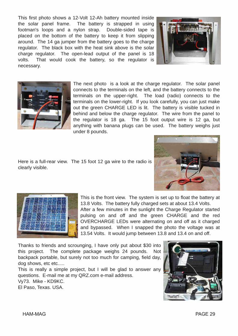
This first photo shows a 12Volt 12Ah battery mounted insidethe solar panel frame. The battery is strapped in usingfootman's loops and a nylon strap. Doublesided tape isplaced on the bottom of the battery to keep it from slippingaround. The 14 ga jumper from the battery goes to the chargeregulator. The black box with the heat sink above is the solarcharge regulator. The openlead output of the panel is 18volts. That would cook the battery, so the regulator isnecessary.
The next photo is a look at the charge regulator. The solar panelconnects to the terminals on the left, and the battery connects to theterminals on the upperright. The load (radio) connects to theterminals on the lowerright. If you look carefully, you can just makeout the green CHARGE LED is lit. The battery is visible tucked inbehind and below the charge regulator. The wire from the panel tothe regulator is 18 ga. The 15 foot output wire is 12 ga, butanything with banana plugs can be used. The battery weighs justunder 8 pounds.
Here is a fullrear view. The 15 foot 12 ga wire to the radio isclearly visible.
This is the front view. The system is set up to float the battery at13.8 Volts. The battery fully charged sets at about 13.4 Volts.After a few minutes in the sunlight the Charge Regulator startedpulsing on and off and the green CHARGE and the redOVERCHARGE LEDs were alternating on and off as it chargedand bypassed. When I snapped the photo the voltage was at13.54 Volts. It would jump between 13.8 and 13.4 on and off.
Thanks to friends and scrounging, I have only put about $30 intothis project. The complete package weighs 24 pounds. Notbackpack portable, but surely not too much for camping, field day,dog shows, etc etc.....This is really a simple project, but I will be glad to answer anyquestions. Email me at my QRZ.com email address.Vy73. Mike KD9KC.El Paso, Texas. USA.

C6APR Again Pete,W2GJ; Ed, K3IXD; Dallas,W3PP; and Randy, K4QO will operate in theMultiOperator, Two Transmitters (M/2) Class inthe CQ WW SSB contest from the CrookedIsland Lodge (Grid FL22), Crooked Island, TheBahamas. The team will be active from 22October thru 26 October.Before and after the contest look for C6AQO onHF CW and SSB, and C6AXD on HF RTTY.Both C6AQO and C6AXD will be on 160m thru10m including the WARC bands.All the QSOs are good for IOTA NA113 andARLHS light house BAH005.All QSLs via K3IXD.73, EdK3IXD
Hi all ! I am happy to report that 220 mhz is comming back to ottawa here we now haveabout 30 hams on the band including myself ve3skp with a adi rig works great and a 4 elbeam which get the same range as 2 meters i the thing that upsets me is the facticom/yaesu/kenwood put next to few radios with 220 mhz on them. I think its about time theystarted to remake radios including 220 mhz on them such as the ts 2000 when you look atthis rig it has all bands on it but not the 220 mhz so its not realy a all band radio is!so if they did put 220 mhz in it would be all band i know i have the kenwood ts 200x modelwhich you can rec 220 mhz so come on guys get on 220 mhz its a great band! if any ofyou out the have any thoughts on this?73 from VE3SKP, steve in ottawa

The Mongolian Amateur Radio Society (MARS) promotes and organizes the “Mongolian DXContest”. MARS has the honor to invite all Licensed Amateurs and SWLs throughout the Worldto participate the annual "Mongolian DX Contest.Purpose of contest• The objective of the contest is to establish as many contacts as possible between RadioAmateurs around the World and Radio Amateurs of Mongolia.Contest period: Third weekend of the November (21/22) / Time: Saturday 00:00 UTC –Sunday 23:59 (24 hours)Contest Mode: CW SSB RTTYAll participants must enter the contest only one of the category above. However, participantswho entered by different mode shall submit separate log for each mode.Bands: 16010 meter (no WARC, no cross bands)Categories: SOMBCWLP* SOMBSSBLP SOMBRTTYLP SOMBCWHP* SOMBSSBHP SOMBRTTYHP MOSTMixedHP SWLABMixedLP: Less than 100 W HP: Must not exceed the power in the regulations Governing theLicence of the station.Contest call: CQ JT TEST Number exchange: RST report plus CQ ZoneWork stations: Every station can be contacted once per band and mode.Points: QSO with own country 1 point QSO between JT stations 0 point QSO with a differentcountry on your continent 2 points QSO with another continent 3 points SWL One way QSOreception 1 point Two way QSO receptions 3 pointsMultipliers: A multiplier one for each different DXCC Country (Except JT) contacted on eachband A multiplier one for each different JT station contacted one each bandFinal scores: The final score is the results of the total QSO points multiplied by the sum ofDXCC countries and JT stations on all bands.Awards: A special plaque will be issued for the winners of first, second and third places of eachcategory.Logs: Deadline is December 31, 2009• Electronic logs should be submitted via email to [email protected]• Paper logs send toMongolian DX ContestP.O. Box 830,Ulaanbaatar24,Mongolia

CCOOMMIICC''SS HHAAMMHHaavvee ssoommee ffuunn
THE QSL OF THE MONTH
SPECIAL HOLIDAYS


![IPTV SD / HD Set-Top Box MAG-200 - infomir.com.uasoft.infomir.com.ua/mag250/Doc/User_Guide_rev1.2_[ENG].pdf · MAG-200. User Guide (Rev 1.2 05/02/2010,17:23) Precautions Read and](https://img.dokumen.tips/doc/110x75/5a79a1627f8b9ade698da4ae/iptv-sd-hd-set-top-box-mag-200-engpdfmag-200-user-guide-rev-12-050220101723.jpg)


![Ham [Read-Only] Ham Beetles, Cheese Skippers, Ham Mites](https://img.dokumen.tips/doc/110x75/5abdea347f8b9a7e418c3fd3/ham-read-only-ham-beetles-cheese-skippers-ham-mites.jpg)


