Embed Size (px)
Citation preview
H.264 SuccessorHigh Efficiency Video Coding (HEVC), H.265
HEVC or H.265 is the successor of H.264 in the MPEG standardization process.There was a Call for Evidence on High Performance Video Coding in 2009, and the first JCT-VC for reviewing the submission for HEVC was held in April of 2010 in Dresden.(from: “Special Section on the Joint Call for Proposals on High Efficiency Video Coding (HEVC) Standardization, IEEE Transactions on Circuits and Systems for Video Technology, Dec. , 2010, by G. Sullivan et al. [1]).
The goals of this standardization process:Application for video sequences also for higher resolutions, in application areas like HDTV, Blu-Ray video, HD video on demand, internet delivery, or video for mobile devices.At the higher resolutions we can use more of the redundancies in our videos, and especially for video-streaming over mobile devices lower bit rates and limited complexity are important. These emerging applications are the target for the HEVC standardization.
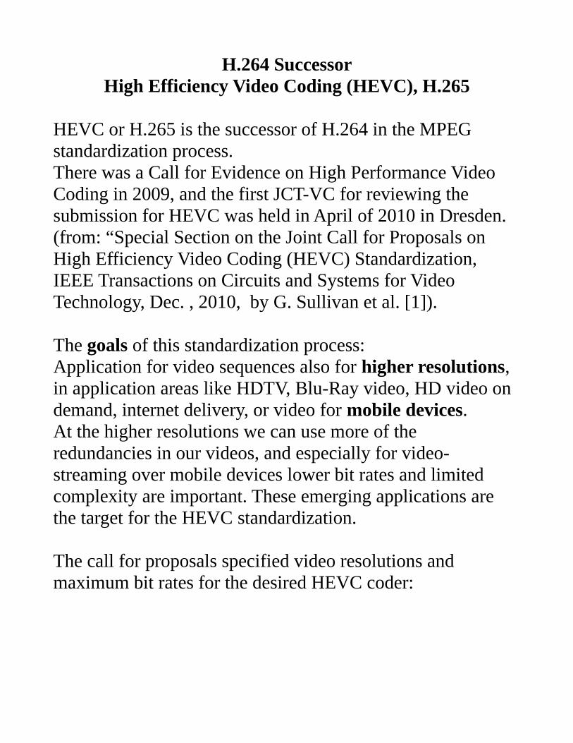
The call for proposals specified video resolutions and maximum bit rates for the desired HEVC coder:
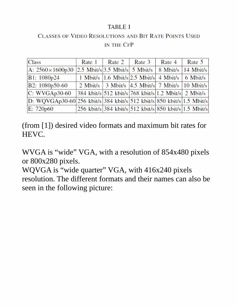
(from [1]) desired video formats and maximum bit rates for HEVC.
WVGA is “wide” VGA, with a resolution of 854x480 pixels or 800x280 pixels.WQVGA is “wide quarter” VGA, with 416x240 pixels resolution. The different formats and their names can also be seen in the following picture:
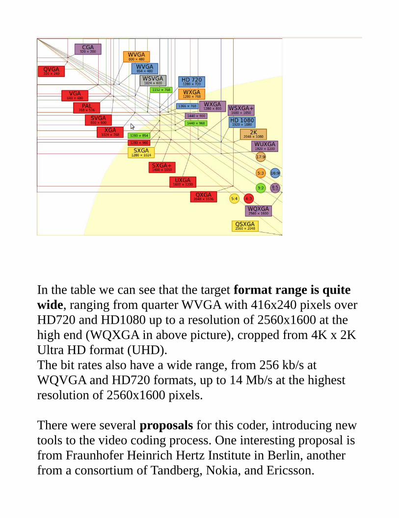
In the table we can see that the target format range is quite wide, ranging from quarter WVGA with 416x240 pixels over HD720 and HD1080 up to a resolution of 2560x1600 at the high end (WQXGA in above picture), cropped from 4K x 2K Ultra HD format (UHD).The bit rates also have a wide range, from 256 kb/s at WQVGA and HD720 formats, up to 14 Mb/s at the highest resolution of 2560x1600 pixels.
There were several proposals for this coder, introducing new tools to the video coding process. One interesting proposal is from Fraunhofer Heinrich Hertz Institute in Berlin, another from a consortium of Tandberg, Nokia, and Ericsson.
A few interesting tools are as follows:
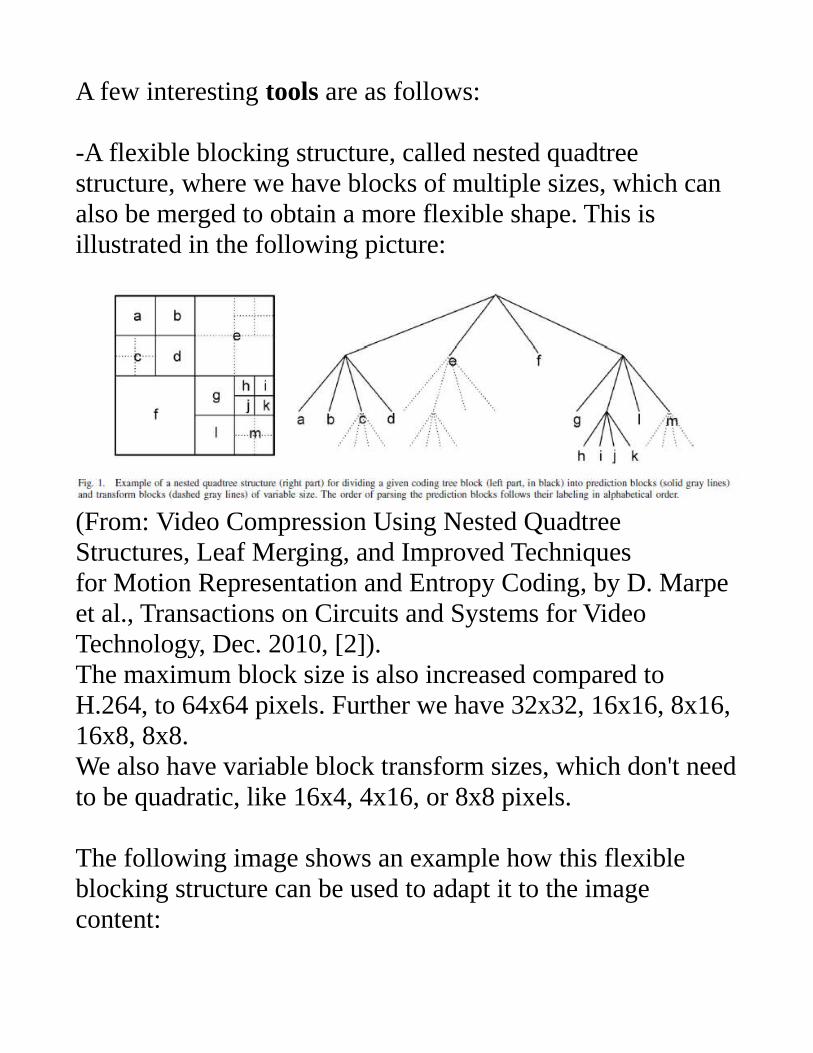
-A flexible blocking structure, called nested quadtree structure, where we have blocks of multiple sizes, which can also be merged to obtain a more flexible shape. This is illustrated in the following picture:
(From: Video Compression Using Nested QuadtreeStructures, Leaf Merging, and Improved Techniquesfor Motion Representation and Entropy Coding, by D. Marpe et al., Transactions on Circuits and Systems for Video Technology, Dec. 2010, [2]).The maximum block size is also increased compared to H.264, to 64x64 pixels. Further we have 32x32, 16x16, 8x16, 16x8, 8x8.We also have variable block transform sizes, which don't needto be quadratic, like 16x4, 4x16, or 8x8 pixels.
The following image shows an example how this flexible blocking structure can be used to adapt it to the image content:
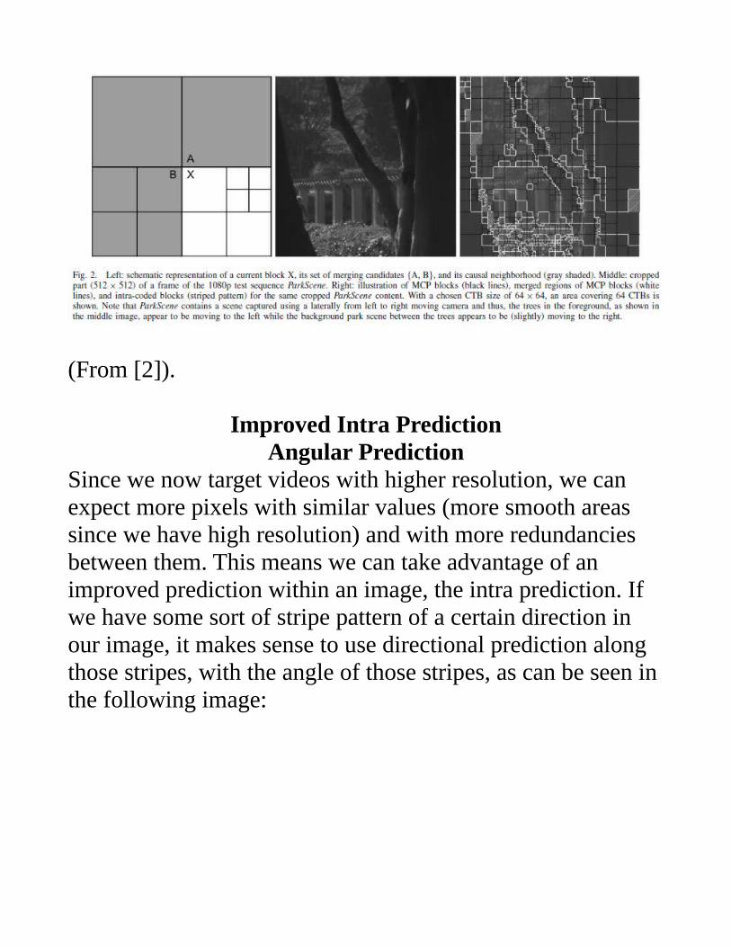
(From [2]).
Improved Intra PredictionAngular Prediction
Since we now target videos with higher resolution, we can expect more pixels with similar values (more smooth areas since we have high resolution) and with more redundancies between them. This means we can take advantage of an improved prediction within an image, the intra prediction. If we have some sort of stripe pattern of a certain direction in our image, it makes sense to use directional prediction along those stripes, with the angle of those stripes, as can be seen in the following image:
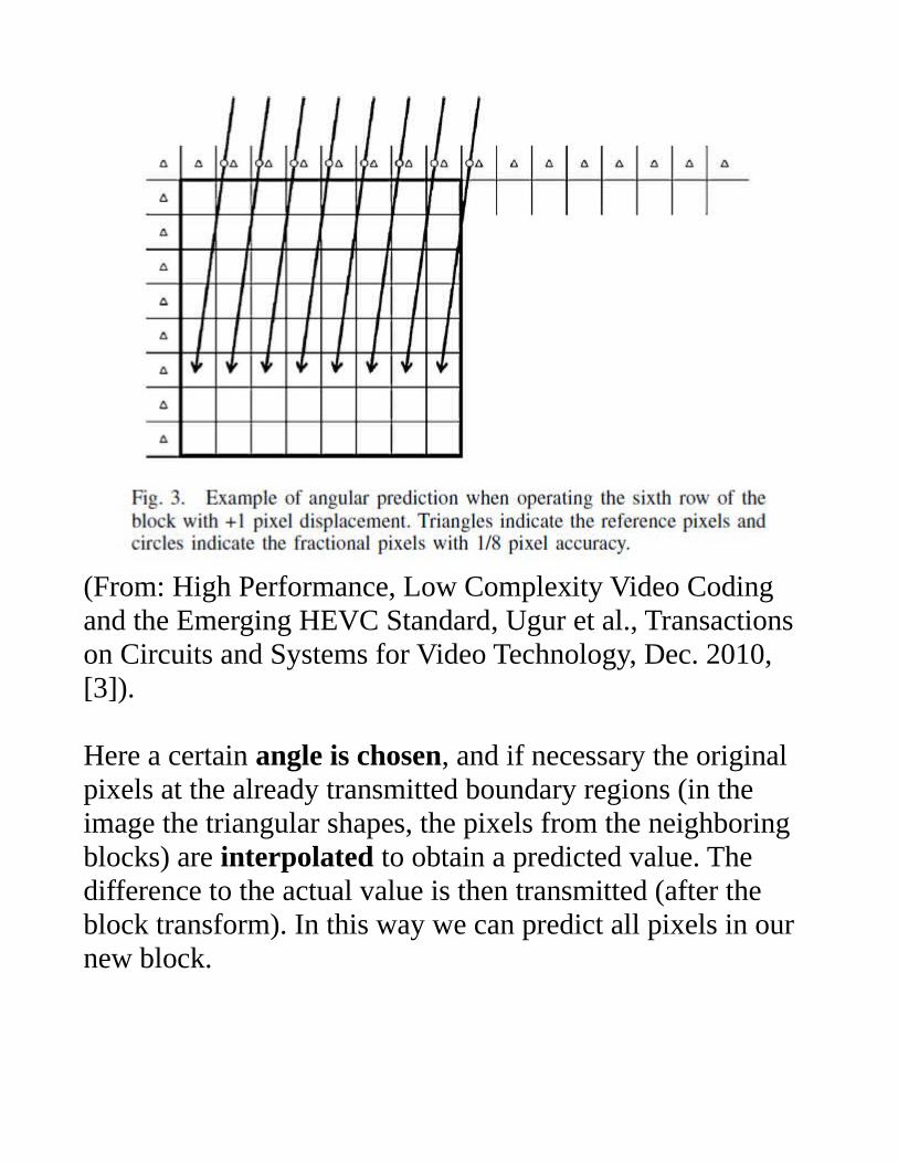
(From: High Performance, Low Complexity Video Codingand the Emerging HEVC Standard, Ugur et al., Transactions on Circuits and Systems for Video Technology, Dec. 2010, [3]).
Here a certain angle is chosen, and if necessary the original pixels at the already transmitted boundary regions (in the image the triangular shapes, the pixels from the neighboring blocks) are interpolated to obtain a predicted value. The difference to the actual value is then transmitted (after the block transform). In this way we can predict all pixels in our new block.
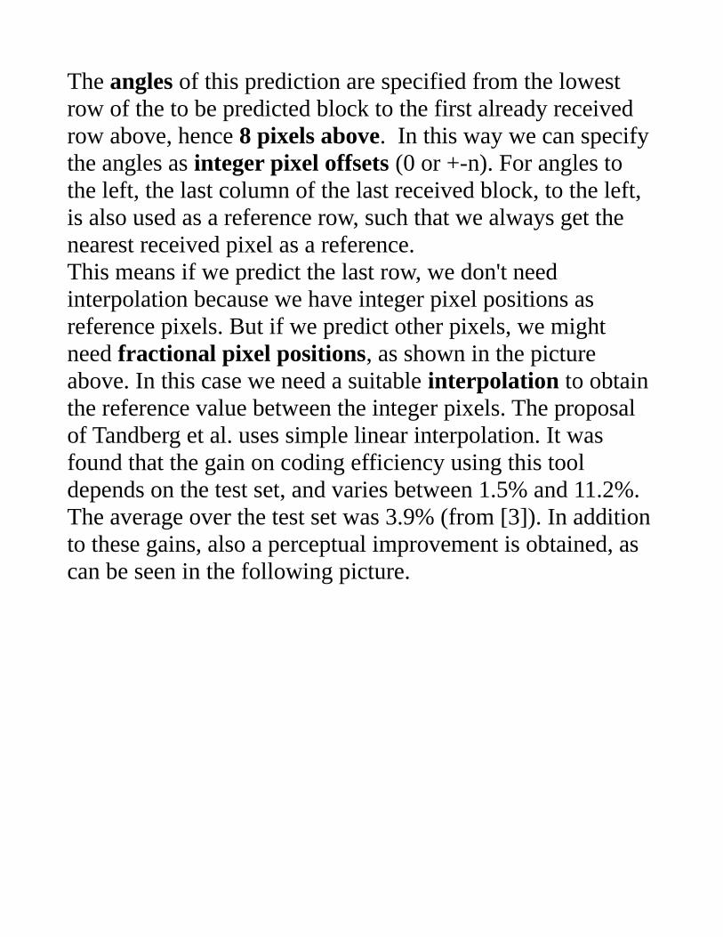
The angles of this prediction are specified from the lowest row of the to be predicted block to the first already received row above, hence 8 pixels above. In this way we can specify the angles as integer pixel offsets (0 or +-n). For angles to the left, the last column of the last received block, to the left, is also used as a reference row, such that we always get the nearest received pixel as a reference.This means if we predict the last row, we don't need interpolation because we have integer pixel positions as reference pixels. But if we predict other pixels, we might need fractional pixel positions, as shown in the picture above. In this case we need a suitable interpolation to obtain the reference value between the integer pixels. The proposal of Tandberg et al. uses simple linear interpolation. It was found that the gain on coding efficiency using this tool depends on the test set, and varies between 1.5% and 11.2%. The average over the test set was 3.9% (from [3]). In additionto these gains, also a perceptual improvement is obtained, as can be seen in the following picture.
(From [3])
This tools is useful for stripe like patterns. The encoder choses this tool if good prediction performance is found.For more even patterns, the following tool is intended:
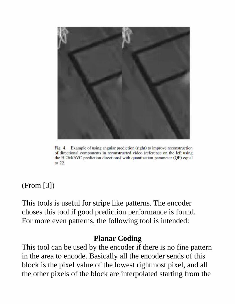
Planar CodingThis tool can be used by the encoder if there is no fine patternin the area to encode. Basically all the encoder sends of this block is the pixel value of the lowest rightmost pixel, and all the other pixels of the block are interpolated starting from the
already received pixels to the left and above.In this way we get smooth planar values for our pixels. This process is illustrated in the following picture:
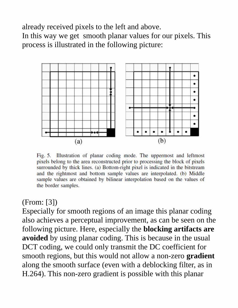
(From: [3])Especially for smooth regions of an image this planar coding also achieves a perceptual improvement, as can be seen on thefollowing picture. Here, especially the blocking artifacts are avoided by using planar coding. This is because in the usual DCT coding, we could only transmit the DC coefficient for smooth regions, but this would not allow a non-zero gradientalong the smooth surface (even with a deblocking filter, as in H.264). This non-zero gradient is possible with this planar
coding.
(From [3]).Observe that in planar mode, no residual signal is transmitted!This can also be seen as encoding a smooth region with only 1/8th of the pixels along each dimension (downsampling by afactor of 8 along dimension x and y), or with 1/64th the number of pixels for a 2-dimensional region. This donwsampling can be efficiently done since there are no high spacial frequencies in the smooth region. The decoder then just upsamples and interpolates the region to fit into the reconstructed image.
In-Loop FilteringThe proposal by HHI includes a deblocking filter and a

subsequent quadtree based separable 2-D Wiener filter.The Wiener filter is applied to reduce additional quantization noise after the deblocking filter.The deblocking filter is a straightforward extension of the oneused in H.264 for the HHI proposal. Tandberg proposes a more modified de-blocking filter.
Spatially Varying TransformThe Tandberg proposal has a spatially varying transform. Here we not only have transform blocks which are identical to the processing blocks, but also the possibility of smaller blocks, and even non-quadratic blocks. Here we also need an offset information, to specify the position of the transform inside the block. This can be seen on the following picture.
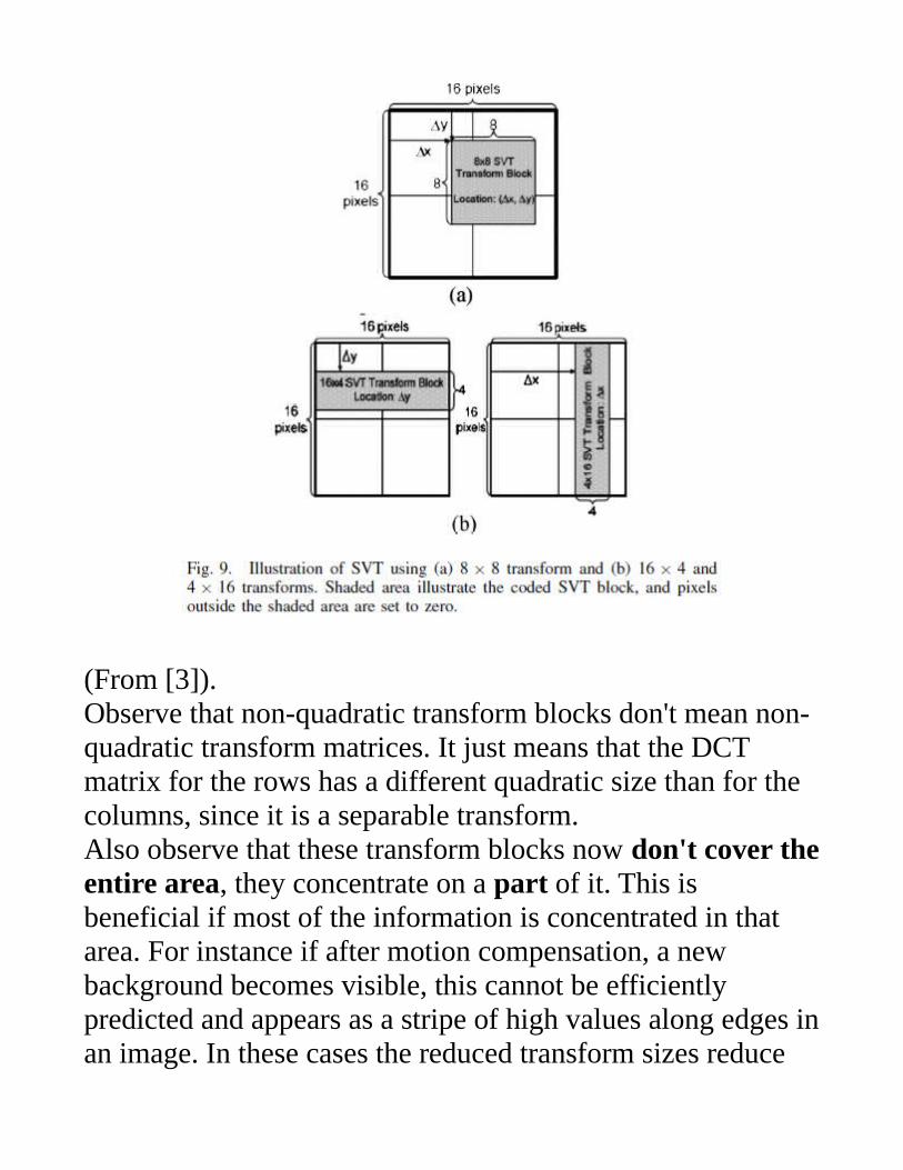
(From [3]).Observe that non-quadratic transform blocks don't mean non-quadratic transform matrices. It just means that the DCT matrix for the rows has a different quadratic size than for the columns, since it is a separable transform.Also observe that these transform blocks now don't cover theentire area, they concentrate on a part of it. This is beneficial if most of the information is concentrated in that area. For instance if after motion compensation, a new background becomes visible, this cannot be efficiently predicted and appears as a stripe of high values along edges inan image. In these cases the reduced transform sizes reduce
the complexity and also the information needed to be transmitted. The proposal uses transform block sizes of 16x4, 4x16, and 8x8.In this way we get some dependency of the transform block shape on the image content. In H.264 we had this dependencyonly for the transform block size. But it seems this tool did not make it into the final standard.
Skip Mode
In this mode, almost no information is transmitted to the decoder. This is useful for very smooth regions with common movement. For instance for the inner blocks of a moving object. The encoder just signals, which motion vector is to be used (1 of 2 candidates with 1 bit), and the decoder only uses this motion vector to reconstruct the block, without any residual.
Improved Fractional Sample Interpolation
The proposal from HHI includes an interesting improved fractional sample interpolation, which is used for the motion compensation/prediction. We need an interpolation, because usually the reference values are not at integer pixel positions.We had this approach with using a correspondingly increased reference picture. For instance, for a quarter pixel motion accuracy, we need to increase the reference picture size by a factor of 4 along each dimension, x and y. But how do we get
precise interpolated values, in between the original pixels?In this case, how do we get those 3 new pixel values for each old pixel along x and y? The simplest way would be to simplyrepeat the last pixel value, but this usually gives not a good estimate of the real image values. So far we used bi-linear interpolation, but it also turns out to be not precise enough for many natural images.On the other extreme, we have an ideal low pass filter, with which we filter the upsampled image (insert 3 zeros after eachpixel along x and y). This would give us very precise image values, if the original image is band limited according to Nyquist. But this requirement is also often not realistic, and also the ideal low pass filter would require a sinc impulse response, which is infinitely long, and hence would be very complex to apply.Hence we are looking for a good compromise, with low complexity, but also with good approximation properties. Theinterpolated values should be as close as possible to the “real”image.

Video DemoAcronyms:CU: Coding unit, the blocks for coding.PU: Prediction unit, the block for the predictionTU: Transform unit, the blocks for which we apply the transform.
-Above right: CU- Partitioning (red: intra, blue: inter, green: skip) with motion vectors. -Lower left: Reference-indices of each PUs (blue: previous frame, orange: second reference frame, green: third reference frame etc.)-Lower right: TU- Partitioning, white lines signal further (finer) sub division of the CU's into sub- TU's.
Videos courtesy of Dominic Springer, Lehrstuhl fuer Nachrichtentechnik, University Erlangen-Nuremberg.