Embed Size (px)
Citation preview

04.2019BAUSYSTEME
BUILDING SYSTEMS
METALLVERBUND & ALUMINIUM SYSTEME
METAL-COMPOSITE & ALUMINUM SYSTEMS
KATALOG
CATALOGUE
GUT�ANN FPS.I - Integrated Fall Prevention SystemGUT�ANN FPS.I - Integrierte Absturzsicherung
w w w . g u t m a n n - b a u s y s t e m e . d e
A LU M I N I U M S H A P E D BY G U T M A N N
DESIGNED ENGINEERED M A D E I N G E R M A N Y

GUTMANN GROUP
Die GUTMANN Bausysteme GmbH ist ein internationaler Anbieter von systembasierten Aluminiumlösungen für Gebäude. GUTMANN Bausysteme stehen für moderne Fenster-, Türen- und Fassadensysteme, die den vielfältigen Anforderungen von Architekten, Investoren und Bauherren an Stil, Design und Energieeffi zienz optimal gerecht werden.
Seit über 70 Jahren ist die GUTMANN Bausysteme GmbH in diesem Segment präsent und hat sich zusammen mit den anderen Unternehmen der Gruppe, der GUTMANN AG, der GARTNER EXTRUSION GmbH, der NORDALU GmbH und der GUTMANN ALUMINIUM DRAHT GmbH – auch im Bereich Aluminium-profi le und Spezialdrähte zu einem Hersteller von hochwertigen Produkten entwickelt.
Die Nähe zum Kunden, das Engagement der 1300 Mitarbeiterinnen und Mitarbeiter sowie die hohe Innovationskraft haben dieGUTMANN Gruppe zu einem zuverlässigen internationalen Partner für Aluminiumprodukte gemacht. Diese Qualitäten bilden gleichzeitig eine solide Basis für das weitere Wachstum des leistungsfähigen Unternehmensverbundes.
GUTMANN Bausysteme GmbH is an international supplier for sys-tem-based aluminium building solutions. GUTMANN Building Sys-tems are designed for modern windows, doors and curtain-wall systems that are optimised and customised for the wide range of stylistic, design and energy-effi ciency requirements demanded by architects, investors and fabricators.
With more than 70 years of presence in the fi eld, GUTMANN Bausysteme GmbH together with its holding companies, GUTMANN AG, GARTNER EXTRUSION GmbH, NORDALU GmbH and GUTMANN ALUMINIUM DRAHT GmbH, has also become a producer of high-quality Aluminium Profi les and Specialized Wire.
Customer proximity, 1300 committed employees and high innova-tive power have made the GUTMANN Group a trusted international partner for aluminium products. These qualities also form a solid base for continued growth in the future.
Aluminium SystemeAluminium Systems
Metallverbund SystemeMetal-Composite Systems
Holz-Aluminium SystemeWood-Aluminium Systems
Kunststoff -Aluminium SystemePVC-Aluminium Systems
SpezialdrähteSpecialized Wire
Baubeschlag SystemeBuilding-Fitting Systems
Aluminiumprofi leAluminium Profi les
BausystemeBuilding Systems
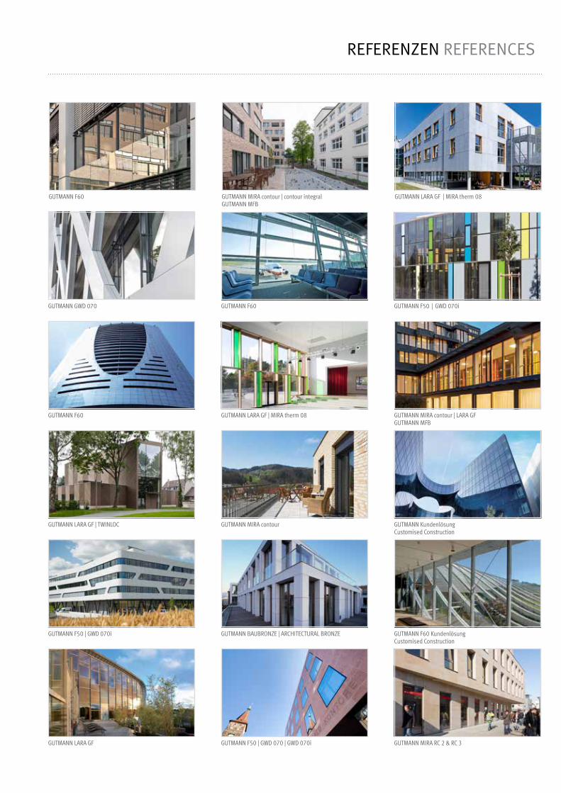
REFERENZEN REFERENCES
GUTMANN F60 GUTMANN MIRA contour | contour integralGUTMANN MFB
GUTMANN GWD 070 GUTMANN F60 GUTMANN F50 | GWD 070i
GUTMANN F60 GUTMANN LARA GF | MIRA therm 08 GUTMANN MIRA contour | LARA GFGUTMANN MFB
GUTMANN LARA GF | TWINLOC GUTMANN MIRA contour
GUTMANN F50 | GWD 070i
GUTMANN LARA GF GUTMANN MIRA RC 2 & RC 3
GUTMANN LARA GF | MIRA therm 08
GUTMANN BAUBRONZE | ARCHITECTURAL BRONZE GUTMANN F60 KundenlösungCustomised Construction
GUTMANN F50 | GWD 070 | GWD 070i
GUTMANN KundenlösungCustomised Construction
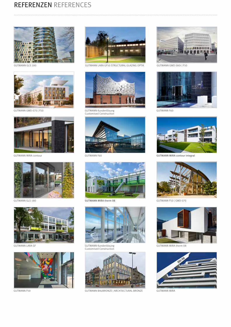
GUTMANN GLS 180 GUTMANN LARA GF50 STRUCTURAL GLAZING OPTIK GUTMANN GWD 080i | F50
GUTMANN GWD 070 | F50 GUTMANN KundenlösungCustomised Construction
GUTMANN F60
GUTMANN MIRA contour GUTMANN F60 GUTMANN MIRA contour integral
GUTMANN GLS 180 GUTMANN MIRA therm 08 GUTMANN F50 | GWD 070
GUTMANN LARA GF GUTMANN KundenlösungCustomised Construction
GUTMANN MIRA therm 08
GUTMANN F50 GUTMANN BAUBRONZE | ARCHTIECTURAL BRONZE GUTMANN MIRA
REFERENZEN REFERENCES

INHALT CONTENT
Kapitel 1Chapter 1
ArtikelübersichtArticle overview 6-10
Kapitel 2Chapter 2
HinweisNote 11
Kapitel 3Chapter 3
FPS.I Details MIRAFPS.I details MIRA 12 - 18
Kapitel 4Chapter 4
FPS.I Details MIRA contourFPS.I details MIRA contour 19 -30
Kapitel 5Chapter 5
FPS.I Details MIRA contour integral FPS.I details MIRA contour integral 32 - 41
Kapitel 6Chapter 6
VerarbeitungshinweiseProcessing guidelines 43- 48
Kapitel 7Chapter 7
GlasstatikGlass static 49 - 55
Kapitel 8Chapter 8
Technische HinweiseTechnical guidelines 56 - 59
Kapitel 9Chapter 9
Pflege und WartungCare and maintenace 60 - 61
Bitte beachten:Mit dem Erscheinen der neuen Kataloge erhalten alle Verarbeitungszeichnungen eine sogenannte „K-Nummer“,diese Nummer dient der eindeutigen Identifizierung einer Zeichnung und ihres Versionsstandes. Da diese Zeichnungen die technischen Entwicklungen dokumentieren und dem Änderungsdienst unterliegen, geben Sie zukünftig bei evtl. Rückfragen zur Verarbeitung stets diese Nummer an.
Die Weiterverarbeitung von GUTMANN Produkten bedarf grundsätzlich Fachkenntnisse des Tischlerei- oder Metallbauhandwerks.Diese Montageanleitung gilt nur in Verbindung mit weiteren produktspezifischen Dokumenten, im Besonderender Bestell- und Verarbeitungshinweise. Die aktuellen Systemunterlagen finden sie unter: http://www.gutmann-group.com
Please note:With the advent of new catalogs all processing drawings received so-called “K-number”. This number is used to uniquely identify a drawing and its version level.These drawings document the technical developments and are a subject for updating. For the future - in case of questions for processing, please refer to this number.
The further processing of GUTMANN products require specific knowledge of carpentry or metal construction craft.This assembly instruction are only valid in combination with other product-specific dokuments, particular with the order and processing guidelines. The current system documents are available at: http://www.gutmann-group.com

1
04.2019
6 | GUTMANN FPS.I Article overviewArtikelübersicht
ArtikelnummerItem number 598864ProduktbezeichungProduct designation BR 66.14 R2Produkt GruppeProduct group
BlendrahmenprofilFrame profile
SystemSystem
MaterialMaterial
VEPU
MIRA Aluminium 6,00 m
ArtikelnummerItem number 598862ProduktbezeichungProduct designation BR 86.14 R2Produkt GruppeProduct group
BlendrahmenprofilFrame profile
SystemSystem
MaterialMaterial
VEPU
MIRA Aluminium 6,00 m
ArtikelnummerItem number 553435ProduktbezeichungProduct designation BR 68.14-SKProdukt GruppeProduct group
BlendrahmenprofilFrame profile
SystemSystem
MaterialMaterial
VEPU
MIRA contour Aluminium 6,00 m
ArtikelnummerItem number 553808ProduktbezeichungProduct designation BR 88.14-SKProdukt GruppeProduct group
BlendrahmenprofilFrame profile
SystemSystem
MaterialMaterial
VEPU
MIRA contour Aluminium 6,00 m
ArtikelnummerItem number 554779ProduktbezeichungProduct designation BR 68.25-SKProdukt GruppeProduct group
BlendrahmenprofilFrame profile
SystemSystem
MaterialMaterial
VEPU
MIRA contour Aluminium 6,00 m
68
14.5
39
R0.5
EW 3000 NASW-BR
EW 3000 N EW 3000 NASW-BR
88
14.5
39 19.7
R0.5
ArtikelnummerItem number 554273ProduktbezeichungProduct designation WG 88.14-SKProdukt GruppeProduct group
EinspannrahmenFrame profile
SystemSystem
MaterialMaterial
VEPU
MIRA contour Aluminium 6,00 m
EW 770426
EW 3000 N
88
14.5
39
38.4
R0.5
ASW-BR
68
25.5
EW 3000 N
EW 770426
AW 7
-30
39
R0.5
66
37
14.5
R2
20°EW 3000 NASW-BR
86
14.5
37
R2
20°EW 3000 N EW 3000 NASW-BR
19.7

04.2019
GUTMANN FPS.I | 7Article overviewArtikelübersicht
1
ArtikelnummerItem number 587870ProduktbezeichungProduct designation SL 66.1Produkt GruppeProduct group
SchlagleisteRasp bar
SystemSystem
MaterialMaterial
VEPU
M/Mc Aluminium 6,00 m
ArtikelnummerItem number 588079ProduktbezeichungProduct designation SL 56.1Produkt GruppeProduct group
SchlagleisteRasp bar
SystemSystem
MaterialMaterial
VEPU
M/Mc Aluminium 6,00 m
16
56.5
37.51
66
16
37.5
1
108
14.5
62
R0.5
EW 3000 NEW 770426
EW 770426
35.4
ArtikelnummerItem number 554717ProduktbezeichungProduct designation WG 108.14 SK-IProdukt GruppeProduct group
EinspannrahmenFrame profile
SystemSystem
MaterialMaterial
VEPU
MIRA contour integral Aluminium 6,00 m
ArtikelnummerItem number 553541ProduktbezeichungProduct designation BR 88.14 SK-IProdukt GruppeProduct group
BlendrahmenprofilFrame profile
SystemSystem
MaterialMaterial
VEPU
MIRA contour integral Aluminium 6,00 m
EW 3000 NEW 770426
88
14.5
62
R0.5
ArtikelnummerItem number 553723ProduktbezeichungProduct designation SH 124.14-SKProdukt GruppeProduct group
SetzholzprofilMullion profile
VE | PU 6,00 mSystemSystem
MaterialMaterial
MIRA contour Aluminium
124
14.5
39
R0.5

1
04.2019
8 | GUTMANN FPS.I Article overviewArtikelübersicht
15.1
8.1
ArtikelnummerItem number 553336ProduktbezeichungProduct designation H 15/8Produkt GruppeProduct group
HalteprofilHolder profile
MaterialMaterial
VEPU
Aluminium 6,00 m
25
16
ArtikelnummerItem number 553264ProduktbezeichungProduct designation H 25/16Produkt GruppeProduct group
HalteprofilHolder profile
MaterialMaterial
VEPU
Aluminium 6,00 m
13
6
11.4
ArtikelnummerItem number 553368ProduktbezeichungProduct designation KTS 13.6Produkt GruppeProduct group
KantenschutzEdge guard
Für Glasdicke 10.76 | For glass thickness 10.76MaterialMaterial
VEPU
Aluminium 6,00 m
15.6
6
14
ArtikelnummerItem number 553584ProduktbezeichungProduct designation KTS 15.6Produkt GruppeProduct group
KantenschutzEdge guard
Für Glasdicke 12.76 | For glass thickness 12.76MaterialMaterial
VEPU
Aluminium 6,00 m
19.6
6
18
ArtikelnummerItem number 553586ProduktbezeichungProduct designation KTS 19.6Produkt GruppeProduct group
KantenschutzEdge guard
Für Glasdicke 16.76 | For glass thickness 16.76MaterialMaterial
VEPU
Aluminium 6,00 m
24.1
6
22.5
ArtikelnummerItem number 554659ProduktbezeichungProduct designation KTS 24.6Produkt GruppeProduct group
KantenschutzEdge guard
Für Glasdicke 20.76 | For glass thickness 20.76MaterialMaterial
VEPU
Aluminium 6,00 m
ArtikelnummerItem number E001621ProduktbezeichungProduct designation HA 3070 FPS.IProdukt GruppeProduct group
BlendrahmendichtungWindow frame gasket
Für Flügelversatz 15,5 | For sash offset 15,5MaterialMaterial
VEPU
EPDM 80,0 m
ArtikelnummerItem number E001545ProduktbezeichungProduct designation HA 3073 FPS.IProdukt GruppeProduct group
BlendrahmendichtungWindow frame gasket
Für Flügelversatz 17 | For sash offset 17MaterialMaterial
VEPU
EPDM 80,0 m
1.5
ArtikelnummerItem number 770009ProduktbezeichungProduct designation 770009Produkt GruppeProduct group
VerglasungsdichtungGlazing gasket
MaterialMaterial
VEPU
Silikon 50,0 m
12
5
ArtikelnummerItem number 7000125ProduktbezeichungProduct designation TD 12.5Produkt GruppeProduct group
VerglasungsdichtungGlazing gasket
MaterialMaterial
VEPU
EPDM 100 m
ArtikelnummerItem number 703062ProduktbezeichungProduct designation HA 3062Produkt GruppeProduct group
VerglasungsdichtungGlazing gasket
MaterialMaterial
VEPU
EPDM 100 m
1

04.2019
GUTMANN FPS.I | 9Article overviewArtikelübersicht
1ArtikelnummerItem number E000919ProduktbezeichungProduct designation GA 30.26Produkt GruppeProduct group
GlasauflagerGlass support
Für MIRA Glasstärke 10.76 | For MIRA glass thickness 10.76
MaterialMaterial
VEPU
Kunststoff | plastic 25,0 Paar | pair
ArtikelnummerItem number E000922ProduktbezeichungProduct designation GA 30.26-SKProdukt GruppeProduct group
GlasauflagerGlass support
Für MIRA contour Glasstärke 10.76 For MIRA contour glass thickness 10.76
MaterialMaterial
VEPU
Kunststoff | plastic 25,0+50,0
Paar | pair Keile | wedge
ArtikelnummerItem number E002558ProduktbezeichungProduct designation GA 30.28-SKProdukt GruppeProduct group
GlasauflagerGlass support
Für MIRA contour Glasstärke 12.76 / 16.76 / 20.76 For MIRA contour glass thickness 12.76 / 16.76 / 20.76
MaterialMaterial
VEPU
Aluminium 20,0 Stk.| pcs.
ArtikelnummerItem number E001083ProduktbezeichungProduct designation GA 51.30 SK-IProdukt GruppeProduct group
GlasauflagerGlass support
Für MIRA contour integral Glasstärke 10.76 For MIRA contour integral glass thickness 10.76
MaterialMaterial
VEPU
Aluminium 20,0 Stk.| pcs.
ArtikelnummerItem number 792398ProduktbezeichungProduct designation ASW-BRProdukt GruppeProduct group
AussteifungswinkelCorner brace
Für | For BR 66.14 R2, BR 86.14 R2, BR 68.14-SK, BR 88.14-SK
MaterialMaterial
VEPU
Kunststoff | plastic 100 Stk.| pcs.
ArtikelnummerItem number E003878ProduktbezeichungProduct designation AW 7-30Produkt GruppeProduct group
AussteifungswinkelCorner brace
Für | For BR 68.25-SK
MaterialMaterial
VEPU
Aluminium 20,0 Stk.| pcs.
4.2
14
ArtikelnummerItem number E002535ProduktbezeichungProduct designation VA 4,2 x 14Produkt GruppeProduct group
SchraubeScrew
Für Glasauflage GA 30.28-SK For glass seat GA 30.25-SK
MaterialMaterial
VEPU
V2A 100 Stk.| pcs.
16
3.9
ArtikelnummerItem number 833916ProduktbezeichungProduct designation VA 3.9 x 16Produkt GruppeProduct group
SchraubeScrew
Für Glasauflage GA 30.26 | GA 30.26-SK | GA 51.30 SK-I For glass seat GA 30.26 | GA 30.26-SK | GA 51.30 SK-I
MaterialMaterial
VEPU
V2A 100 Stk.| pcs.
30 3
ArtikelnummerItem number E000989ProduktbezeichungProduct designation VA 3 x 30Produkt GruppeProduct group
SchraubeScrew
MaterialMaterial
VEPU
V2A 200 Stk.| pcs.
40
4
ArtikelnummerItem number E000869ProduktbezeichungProduct designation VA 4 x 40Produkt GruppeProduct group
SchraubeScrew
MaterialMaterial
VEPU
V2A 200 Stk.| pcs.

1
04.2019
10 | GUTMANN FPS.I Article overviewArtikelübersicht
Hinweis: Bei MIRA contour integral sind zusätzlich folgende Artikel zu bestellen:
∙ Dichtung 770009 | Artikel Nr.: 770009 | VE = 50,0 m ∙ Glasauflage GA 51.30 SK-I | Art.-Nr.: E001083 | VE = 20 Stück
Note: The following items must be ordered additionally when usingMIRA contour integral:
∙ Gasket 77009 | Item number: 770009 | PU = 50,0 m ∙ Glass support GA 51.30 SK-I | Item number: E001083 | PU = 20 piece
Bei MIRA contour mit größeren Glasstärkensind zusätzlich folgende Artikel zu bestellen:
∙ Glasauflage GA 51.30 SK-I | Art.-Nr.: E001083 | VE = 20 Stück ∙ Glasstärke 12,76 = KTS 15.6 Art.-Nr.: E001083 | TD 12.5 Art.-Nr.: 7000125 ∙ Glasstärke 16,76 = KTS 19.6 Art.-Nr.: 553586 | HA 3062 Art.-Nr.: 703062 ∙ Glasstärke 21,52 = KTS 24.6 Art.-Nr.: 554659
The following items must be ordered additionally when usingMIRA contour with bigger glass thickness:
∙ Glass support GA 30.28 SKI | Item number: E002558 | PU = 20 piece ∙ Glass thickness 12,76 = KTS 15.6 item nr.: E001083 |
TD 12.5 item nr.: 7000125 ∙ Glass thickness 16,76 = KTS 19.6 item nr.: 553586 |
HA 3062 item nr.: 703062 ∙ Glass thickness 21,52 = KTS 24.6 item nr.: 554659
Zubehör Set Integrierte Absturzsicherung Art.-Nr.: E001022Accessory Set Integrated Fall Prevention System item no.: E001022
Produktbezeichnung Product designation
Artikelnummer Item number
OberflächeSurface
MaterialMaterial
Menge im SetAmount in set
H 15/8 55336 G220 (schwarz | black) Aluminium 2 x 1 m
H 25/16 553264 blank | shiny Aluminium 2 x 1 m
KTS 13.6 553368 EV1 Aluminium 2 x 1,5 m
770009 770009 schwarz | black Silikon 2 x 1 m
HA 3062 703062 schwarz | black EPDM 2 x 1 m
VA 3.9 x 16 833916 blank | shiny V2A 6 Stk.| pcs.
VA 3 x 30 E000989 blank | shiny V2A 16 Stk.| pcs.
VA 4 x 40 E000869 blank | shiny V2A 26 Stk.| pcs.
GA 30.26 SK E000922 schwarz | black ASA 1 Paar | pair

04.2019
GUTMANN FPS.I | 11NoteHinweise
2
Vorteile: ∙ Rahmenintegrierte Absturzhemmung mit perfekter Optik ∙ Glasscheibe kann an Baustelle montiert / demontiert werden ∙ Mit allen Profilen mit Bauhöhe 14,5 mm machbar ∙ Wirtschaftlich und montagefreundlich ∙ Allgemeines Bauaufsichtliches Prüfzeugnis vorhanden
Advantage: ∙ Frame integrated fall prevention with perfect optic ∙ Glass pane can be mounted / demounted on the construction site ∙ Available for all profiles with construction heights 14.5 mm ∙ Economical and easy to assemble ∙ German General Building Inspectorate Approval
Vorgaben für die Befestigung des Rahmens zum MauerwerkDie Befestigung des Rahmens im Mauerwerk ist nach den anerkannten Regeln der Technik und mit für den Anwendungsfall zugelassenen Befestigungsmitteln auszuführen.Die Befestigung ist mit einem zugelassenen Befestigungssystem(z.B. von Firma SFS / Würth / Illbruck) durchzuführen. Weitere Informationen zur Befestigung sind im „Leitfaden zur Monta-ge“, Ausgabe 2014 der RAL-Gütegemeinschaft Fenster und Haustüren, Kapitel 5 enthalten.
Rules for the fastening of the frame to the BrickworkThe fastening of the frame to the Brickwork must be done according to the acknowledged rules of technology and with authorized fasteners. The fixation can be done with a permitted fastening system (for example company SFS / Würth / Illbruck). For more information please see the “Leitfaden zur Montage” of the “RAL-Gütegemeinschaft Fenster und Haustüren”, issue 2014, chapter 5.
Checkliste für erforderliche Maßnahmen zur Ausführung französischer BalkoneImmer erforderliche Unterlagen:Vorgang:
∙ Allgemein bauaufsichtliches Prüfzeugnis muss an den Bauherrn übergeben werden
∙ Übereinstimmungserklärung (Bestätigung der Ausführung gemäß abP, Glasstatik und Standsicherheitsnachweis)
∙ Ansichtsplan mit Gebäudeachsen und Angaben über Stückzahl und Einbauorte im Gebäude
∙ Glasstatik gemäß DIN 18008-4 6.1.1
∙ Ansicht und Schnittzeichnung des Elementes mit Angabe zur Befestigung im Baukörper
∙ Standsicherheitsnachweis mit Lasteinleitung in das Bauwerk
Kommt von:
GUTMANN Bausysteme GmbH
Von Auftragnehmer zu erstellen
Vom Auftaggeber zu erstellen
GUTMANN Bausysteme GmbH
Von Auftagnehmer zu erstellen
Von Auftrageber zu erstellen
evtl. Statiker beauftragen
Das Bauordnungsrecht sieht für französische Balkone aus Glas gemäß DIN 18008 Teil 4 ein allgemein bauaufsichtliches Prüfzeugnis (abP) alsFunktionsnachweis vor. Die im abP beschriebenen Abmessungen sind die Prüfmaße für den Pendelschlag, diese können je nach Wind- undHolmlast durch die Glasstatik eingeschränkt werden.
Bei der Montage von Absturzsicherungen außerhalb von Deutschland sind die vorliegenden deutschen Zulassungen mit den nationalen Normen und Vorschriften des jeweiligen Landes abzugleichen.
Dies gilt besonders für Glastypen und Glasaufbauten. (ggf. sind zusätzliche Prüfungen und Nachweise erforderlich)
When installing the fall prevention outside Germany, the existing German approvals have to be reconciled with the national standards and regulations of the particular country.
This applies especially for glass types and glass superstructures (as the case may be additional tests and proofs are necessary).

3
04.2019
12 | GUTMANN FPS.I Details MIRA Details MIRA
78/81
Nr.
Version:
K-00307
00
78/68
"A"
HG
= H
15/
8
3
3
R3
H 2
5/16
25
12
50
8
17
H 15/8
Auflage GA 30.26-SK
Glasscheibe
FL 4
1.14
R2
BR 6
6.14
R2
WA
min. 10 mmEntwässerungsspalt
KTS 13.6 als Kantenschutz aufgeklebt mit PVB-Folien verträglichem Klebstoff
DH
5-8
DH
4-8
o.A
.
4
206.
53
8
105
16.5
18
16.5
bei RLGU> 30 mm ist ein untererKantenschutz vorzusehen
"HG" = Höhe Glas
"A" = Ausschnitt = HG + 6 mm
"H 25/16" = HG + 50 mm
Support GA 30.26-SK
Glass panel
min. 10 mmdrainage gap
Glue KTS 13.6 as edge guard with ÜVB foil compatible adhesive
when RLGU is bigger than30 mm use an additionaledge guard on thebottom edge
"HG" = Height glass
"A" = Section = HG + 6 mm
"H 25/16" = HG + 50 mm
HA 3073 FPS-I
RLG
U
"RLGU" = Rahmenlichte bis Glasunterkante
"RLGU" = Frame clearance to lower edge of glass
10.76

04.2019
GUTMANN FPS.I | 13Details MIRADetails MIRA
3
Nr.
Version:
K-00308
00
FL 41.14 R2
Glasauflage GA 30.26
78/68
78/81
H 15/8
HA 3062
H 25/16
770009
VA 4 / 40
BR 66.14 R2
VA 3 x 30
20.5
17
Öffnung an Oberkante Scheibe abdichten
1 14
Sichtkontrolle: bündig!
DH 4-8 o.A.
DH 5-8
Glass support GA 30.26
Seal opening on the top of the glass pane
Visual control: flush!
8
8
BR 66.14 R2
78/68
78/81
10.7
6VA 3,9 x 16
3

3
04.2019
14 | GUTMANN FPS.I Details MIRA Details MIRA
78/81
Nr.
Version:
K-00309
00
78/81
817 8
35.5 66 34.5
SL 66.1
HA
3060
m.F
.-NH
A 30
65/4
m.F
.
DH 4-8 o.A. DH 4-8DH 4-8
HA 3070 FPS.I!
! Halter weichen bei Stulpvariante vom Standard ab siehe hierzu Verarbeitungshinweise.Holder deviates from the standard when using double rebate see processing guidelines.
17
BR 6
6.14
R2
16.5
16.5
HA
3062
/2
6
DS 4-EK wird mit einem 1 mmniedrigeren Halter als der Halterdes Stulpprofil befestigt.DS 4-EK has to be mounted withan 1 mm lower holder than theholder for the double rebatedprofile.

04.2019
GUTMANN FPS.I | 15Details MIRADetails MIRA
3
Nr.
Version:
K-00310
00
"A"
HG
= H
15/
8
3
3
R3
H 2
5/16
25
10
50
H 15/8
Auflage GA 30.26-SK
Glasscheibe
KTS 13.6 als Kantenschutz aufgeklebt mit PVB-Folien verträglichem Klebstoff
16.5
20
1210
°
4
30
26
16.5
8
78/80
78/76
BR 6
6.14
R2
HA 3041 N
4
206.
53
Support GA 30.26-SK
Glass panel
Glue KTS 13.6 as edge guard with ÜVB foil compatible adhesive
DH
5-8
DH
4-8
o.A
.
"HG" = Höhe Glas
"A" = Ausschnitt = HG + 6 mm
"H 25/16" = HG + 50 mm
"HG" = Height glass
"A" = Section = HG + 6 mm
"H 25/16" = HG + 50 mm
RLG
U
"RLGU" = Rahmenlichte bis Glasunterkante
"RLGU" = Frame clearance to lower edge of glass
10.76
min. 10 mmEntwässerungsspalt
bei RLGU > 30 mm ist einunterer Kantenschutzvorzusehen
min. 10 mmdrainage gap
when RLGU is bigger than30 mm use an additionaledge guard on thebottom edge
Schrägfalz | Slope reabate

3
04.2019
16 | GUTMANN FPS.I Details MIRA Details MIRA
Nr.
Version:
K-00313
00
FL 41.14 R2
Glasauflage GA 30.26BR 66.14 R2
H 15/8H 25/16
770009
VA 3 x 30
VA 3,9 x 16Öffnung an Oberkante Scheibe abdichten
8
16.5
HA
3060
/5 N
m.F
.H
A 30
65/4
m.F
.
26
78/76
78/80
78/76
15.5
12
17.526
3
8
Im Bereich des vorgesetzten Glases ausfräsen(bandseitig). Nach erfolgter Glasmontage Ausfräsungmit Leiste schließen und abdichten.
Glass overly GA 30.26
Seal opening on the top of the glass pane
Notch in the overlaying glass area (hinge side).After installing the glass, close the hole with astrip and seal it.
HA 3062*
*bei einen Schrägfalzwinkel größer 10° ist die Dichtung HA 3062/2 einzusetzen.*if the slope rebate angele is bigger than 10 ° use gasket HA 3062/2
DH 4-8 o.A.
DH 5-8
DH 5-8
Sichtkontrolle: bündig!Visual control: flush!
BR 66.14 R2
10.7
6
VA 4 x 40
Schrägfalz | Slope reabate

04.2019
GUTMANN FPS.I | 17Details MIRADetails MIRA
3
Nr.
Version:
K-01420
00
FL 41.14 R2
BR 66.14 R2
H 15/8H 25/16
770009
8
16.5
26
78/76
78/80
78/76
15.5
1217.5
3
8
Im Bereich des vorgesetzten Glases ausfräsen(beidseitig). Nach erfolgter Glasmontage Ausfräsungmit Leiste schließen und abdichten.Notch in the overlaying glass area (on bothsides). After installing the glass, close the holewith a strip and seal it.
15
5
HA 3062*
DH 4-8 o.A.
DH 5-8
DH 5-8
HA
3060
/5 N
m.F
.H
A 30
65/4
m.F
.H 25/16
VA 3 x 30
Sichtkontrolle: bündig!Visual control: flush!
Glasauflage GA 30.26Glass overly GA 30.26
BR 66.14 R2
10.7
6
VA 4 x 40
VA 3,9 x 16Öffnung an Oberkante Scheibe abdichten
*bei einen Schrägfalzwinkelgrößer 10° ist die Dichtung HA 3062/2 einzusetzen.*if the slope rebate angele is bigger than 10 ° use gasket HA 3062/2
Seal opening on the top of the glass pane

3
04.2019
18 | GUTMANN FPS.I Details MIRA Details MIRA
Nr.
Version:
K-00317
00
78/76
16.5
20
HA
3065
/4 m
.F.
88
78/76
23.5
34 56.5 34
SL 56.1
HA
3060
m.F
.-N
DH 4-8 o.A. DH 4-8DH 4-8
!
! Halter weichen bei Stulpvariante vom Standard ab siehe hierzu Verarbeitungshinweise.Holder deviates from the standard when using double rebate see processing guidelines.
BR 6
6.14
R2
16.5
HA 3062/2
HA
3041
N 26
16.5
4
Schrägfalz | Slope reabate

04.2019
GUTMANN FPS.I | 19Details MIRA contourDetials MIRA contour
4
Nr.
Version:
K-00314
00
78/68
78/81
"A"
HG
= H
15/
8
3
3
R3
H 2
5/16
25
14
50
8
17
H 15/8
DH
5-8
FL 3
9.14
-SK
BR 6
8.14
-SK
8
105
16.5
4
206.
53
DH
4-8
o.A
.
Auflage GA 30.26-SK
Glasscheibe
KTS 13.6 als Kantenschutz aufgeklebt mit PVB-Folien verträglichem Klebstoff
"HG" = Höhe Glas
"A" = Ausschnitt = HG + 6 mm
"H 25/16" = HG + 50 mm
Support GA 30.26-SK
Glass panel
Glue KTS 13.6 as edge guard with ÜVB foil compatible adhesive
"HG" = Height glass
"A" = Section = HG + 6 mm
"H 25/16" = HG + 50 mm
RLG
U
"RLGU" = Rahmenlichte bis Glasunterkante
"RLGU" = Frame clearance to lower edge of glass
10.76
min. 10 mmEntwässerungsspalt
bei RLGU> 30 mm ist ein untererKantenschutz vorzusehen
min. 10 mmdrainage gap
when RLGU is bigger than30 mm use an additionaledge guard on thebottom edge

4
04.2019
20 | GUTMANN FPS.I Details MIRA contour Details MIRA contour
Nr.
Version:
K-00315
00
78/68
78/81
78/6878/81
H 15/8
HA 3062
H 25/16
770009
20.5
17
2 20
FL 39.14-SK
BR 68.14-SK
8
DH 4-8 o.A.
DH 5-8
DH 5-8VA 3 x 30
Sichtkontrolle: bündig!Visual control: flush!
Glasauflage GA 30.26-SKGlass overly GA 30.26-SK
BR 68.14-SK
10.7
6
VA 4 x 40
Öffnung an Oberkante Scheibe abdichtenSeal opening on the top of the glass pane
VA 3,9 x 16

04.2019
GUTMANN FPS.I | 21Details MIRA contourDetials MIRA contour
4
78/81
Nr.
Version:
K-00316
00
78/81
817 8
35.5 66 34.5
HA 3070 FPS.I
SL 66.1
HA
3060
m.F
.-NH
A 30
65/4
m.F
.
DH 4-8 o.A. DH 4-8DH 4-8
!
! Halter weichen bei Stulpvariante vom Standard ab siehe hierzu Verarbeitungshinweise.Holder deviates from the standard when using double rebate see processing guidelines.
17
16.5
1016.5
HA 3062/2
BR 6
8.14
-SK
8
DS 4-EK wird mit einem 1 mmkleineren Halter als der Halterdes Stulpprofils befestigt.DS 4-EK has to be mounted withan 1 mm smaller holder than theholder for the double rebatedprofile.

4
04.2019
22 | GUTMANN FPS.I Details MIRA contour Details MIRA contour
Nr.
Version:
K-00318
00
78/6
8
78/8
1
H 15/8
HA
3062
H 2
5/16
7700
09SH
124
.14-
SK
VA 3
x 3
0
20.5
VA 3
,9 x
16 Ö
ffnun
g an
Obe
rkan
te S
chei
be a
bdic
hten
2D
icht
ung
vorn
e be
schn
itten
2022
HA 3063 N m.F.HA 3060 m.F.-N
Prof
il SH
124
.14-
SK a
ls z
wei
flüge
liges
Fen
ster
mit
beid
seiti
ger
Abst
urzs
iche
rung
nic
ht m
öglic
h.
17
8
HA 3060/5 N m.F. HA 3065/4 m.F.
DH
5-8
DH
4-8
o.A
.4
206.
53
Seal
ope
ning
on
the
top
of th
e gl
ass
pane
cut g
aske
t in
the
front
Prof
ile S
H 1
24.1
4-SK
as
doub
le-s
ashe
d w
indo
w w
ith fa
ll pr
even
tion
syst
ems
on b
oth
side
s no
t pos
sibl
e.
Die
Ver
bind
ung
zwis
chen
Rah
men
holz
und
Set
zhol
z m
uss
den
Anfo
rder
unge
nfü
r Abs
turz
sich
erhe
it en
tspr
eche
n.Th
e co
nnec
tion
betw
een
fram
e w
ood
and
mul
lion
mus
t be
cond
ucte
d to
the
requ
irem
ents
for f
all p
rote
ctio
n.
!
10.76
VA 4
x 4
0
04.2019
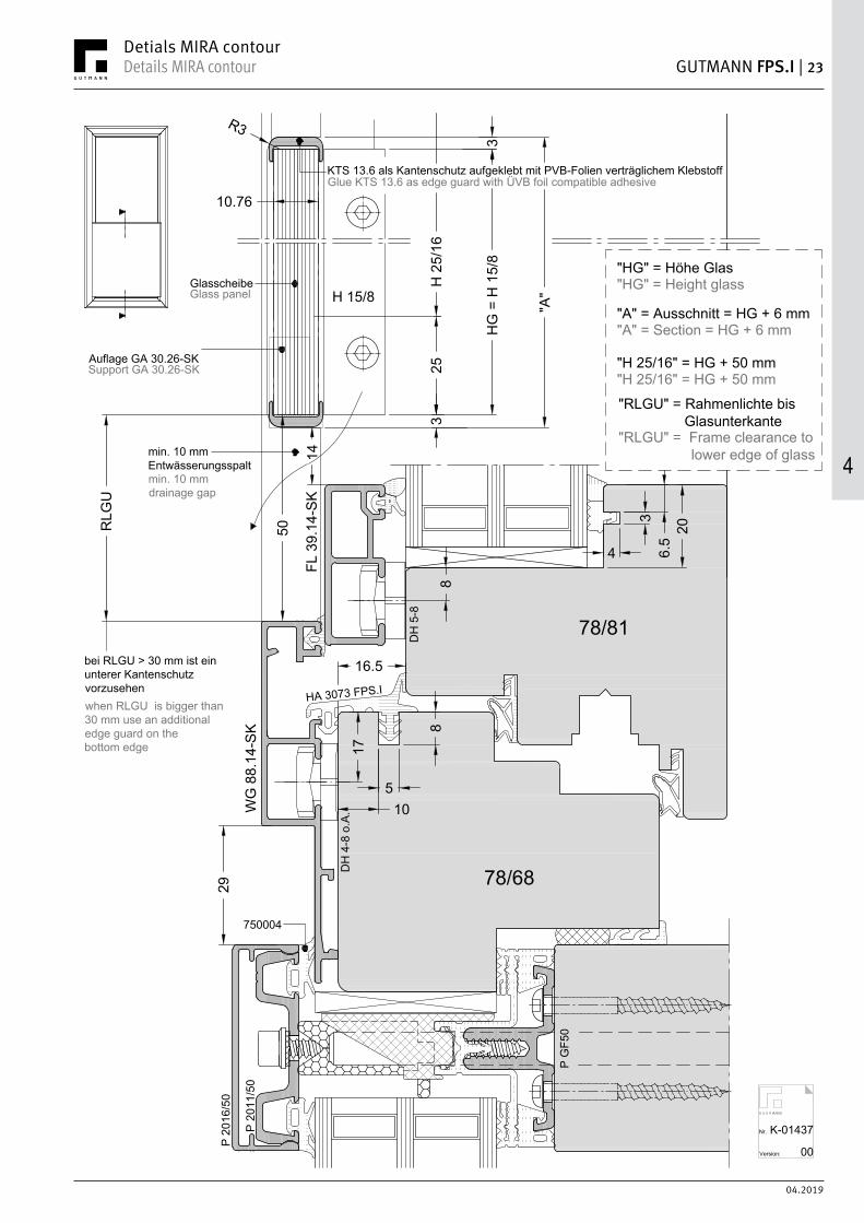
GUTMANN FPS.I | 23Details MIRA contourDetials MIRA contour
4
Nr.
Version:
K-01437
00
78/68
78/81
"A"
HG
= H
15/
8
3
3
R3
H 2
5/16
25
14
50
8
17
H 15/8
Auflage GA 30.26-SK
Glasscheibe
DH
5-8
FL 3
9.14
-SK
WG
88.
14-S
K 8
105
16.5
4
206.
53
Support GA 30.26-SK
Glass panel
HA 3073 FPS.I
P G
F50
P 20
11/5
0
P 20
16/5
0
750004
29
KTS 13.6 als Kantenschutz aufgeklebt mit PVB-Folien verträglichem KlebstoffGlue KTS 13.6 as edge guard with ÜVB foil compatible adhesive
DH
4-8
o.A
.
"HG" = Höhe Glas
"A" = Ausschnitt = HG + 6 mm
"H 25/16" = HG + 50 mm
"HG" = Height glass
"A" = Section = HG + 6 mm
"H 25/16" = HG + 50 mm
"RLGU" = Rahmenlichte bis Glasunterkante
"RLGU" = Frame clearance to lower edge of glass
RLG
U
min. 10 mmEntwässerungsspalt
bei RLGU > 30 mm ist einunterer Kantenschutzvorzusehen
min. 10 mmdrainage gap
when RLGU is bigger than30 mm use an additionaledge guard on thebottom edge
10.76

4
04.2019
24 | GUTMANN FPS.I Details MIRA contour Details MIRA contour
78/68
Nr.
Version:
K-01438
00
10
5
878/68
17
P 2011/50
P 2016/50
7500
04
P GF50
7500
04
H 1
5/8
VA 3 x 30
20.5
2 20
HA 3062
770009
8DH 5-8
FL 39.14-SK
WG 88.14-SK
16.5
HA 3073 FPS.I
Glasauflage GA 30.26-SKGlass overly GA 30.26-SK
8
4
206.5
3
WG 88.14-SK
DK 4-17
Locking screw stainlesssteel V2A Ø 5 every800 mm, min. 2 screwsper side
Sicherungsschraubeaus Edelstahl V2A Ø 5alle 800 mm, min. 2Schrauben pro Seite.
DH 5-8
GF5
0 P-
E3
*
*
78/81
*Optional Glasauflage zur Montagehilfe einsetzen.*Optional use glass support for mounting assistance.
10.7
6
60100
50
100
50
20 - 130
Bearbeitung WG 88.14-SKmechanical processingWG 88.14-SK
Ausfräsung erforderlichzum verschieben desHalteprofils H 25/16Notchig nessesary forshift the holding profileH 25/16

04.2019
GUTMANN FPS.I | 25Details MIRA contourDetials MIRA contour
4
Nr.
Version:
K-00319
00
"A"
HG
= H
15/
8
3
3
R3
H 2
5/16
25
12
50
H 15/8
16.5
20
1210
°
4
30
26
16.5
8
78/80
78/76
HA 3041 N
FL 3
9.14
-SK
BR 6
8.14
-SK
4
206.
53
DH
5-8
DH
4-8
o.A
.
Auflage GA 30.26-SK
Glasscheibe
KTS 13.6 als Kantenschutz aufgeklebt mit PVB-Folien verträglichem Klebstoff
"HG" = Höhe Glas
"A" = Ausschnitt = HG + 6 mm
"H 25/16" = HG + 50 mm
Support GA 30.26-SK
Glass panel
Glue KTS 13.6 as edge guard with ÜVB foil compatible adhesive
"HG" = Height glass
"A" = Section = HG + 6 mm
"H 25/16" = HG + 50 mm
RLG
U
"RLGU" = Rahmenlichte bis Glasunterkante
"RLGU" = Frame clearance to lower edge of glass
min. 10 mmEntwässerungsspalt
bei RLGU > 30 mm ist einunterer Kantenschutzvorzusehen
min. 10 mmdrainage gap
when RLGU is bigger than30 mm use an additionaledge guard on thebottom edge
10.76
Schrägfalz | Slope reabate

4
04.2019
26 | GUTMANN FPS.I Details MIRA contour Details MIRA contour
Nr.
Version:
K-00324
00
H 15/8
HA 3062*
H 25/16
8
16.5
HA
3060
/5 N
m.F
.H
A 30
65/4
m.F
.
26
78/7678/80
78/76
1217.5
3
8
Im Bereich des vorgesetzten Glases ausfräsen(bandseitig). Nach erfolgter Glasmontage Ausfräsungmit Leiste schließen und abdichten.
770009BR 68.14-SK 22
FL 39.14-SK
Notch in the overlaying glass area (hinge side).After installing the glass, close the hole with astrip and seal it.
DH 4-8 o.A.
DH 5-8
DH 5-8
VA 3 x 30
VA 3,9 x 16Öffnung an Oberkante Scheibe abdichtenSeal opening on the top of the glass pane
Sichtkontrolle: bündig!Visual control: flush!
Glasauflage GA 30.26-SKGlass overly GA 30.26-SKBR 68.14-SK
10.7
6
*bei einen Schrägfalzwinkelgrößer 10° ist die Dichtung HA 3062/2 einzusetzen.*if the slope rebate angele is bigger than 10 ° use gasket HA 3062/2
VA 4 x 40
Schrägfalz | Slope reabate

04.2019
GUTMANN FPS.I | 27Details MIRA contourDetials MIRA contour
4
Nr.
Version:
K-00325
00
78/76
16.5
20
HA
3065
/4 m
.F.
88
78/76
23.5
34 56.5 34
SL 56.1
HA
3060
m.F
.-NDH 4-8 o.A. DH 4-8DH 4-8
!
! Halter weichen bei Stulpvariante vom Standard ab siehe hierzu Verarbeitungshinweise.Holder deviates from the standard when using double rebate see processing guidelines.
16.5
HA 3062/2
HA
3041
N 26
16.5
BR 6
8.14
-SK
6
Schrägfalz | Slope reabate

4
04.2019
28 | GUTMANN FPS.I Details MIRA contour Details MIRA contour
Nr.
Version:
K-00326
00
78/9
0
16.5
DH
5-8
16.5
20
HA 3065/4 m.F.
8
78/7
6
12
10°
HA 3063 N m.F.
17.5
Überstand abfräsen
HA
3041
N
SH 1
24.1
4-SK
322
H 15/8
HA
3062
18
HA 3060/5 N m.F.
4
206.
53
Bevel the overlap
DH
4-8
o.A
.
Prof
il SH
124
.14-
SK a
ls z
wei
flüge
liges
Fen
ster
mit
beid
seiti
ger
Abst
urzs
iche
rung
nic
ht m
öglic
h.Pr
ofile
SH
124
.14-
SK a
s du
ble-
sash
ed w
indo
w w
ith fa
ll pr
even
tion
syst
ems
on b
oth
side
s no
t pos
sibl
e.
Die
Ver
bind
ung
zwis
chen
Rah
men
holz
und
Set
zhol
z m
uss
den
Anfo
rder
unge
nfü
r Abs
turz
sich
erhe
it en
tspr
eche
n.Th
e co
nnec
tion
betw
een
fram
e w
ood
and
mul
lion
mus
t be
cond
ucte
d to
the
requ
irem
ents
for f
all p
rote
ctio
n.
!
7700
09
VA 3 x 30
VA 3
,9 x
16 Öffn
ung
an O
berk
ante
Sch
eibe
abd
icht
en
Dic
htun
g vo
rne
besc
hnitt
en
Seal
ing
open
ing
on th
e to
p of
the
glas
s pa
ne
cut g
aske
t in
the
front
VA 4
x 4
0
Im B
erei
ch d
es v
orge
setz
ten
Gla
ses
ausf
räse
n(b
ands
eitig
). N
ach
erfo
lgte
r Gla
smon
tage
Ausf
räsu
ng m
it Le
iste
sch
ließe
n un
d ab
dich
ten.
Not
ch in
the
over
layi
nggl
ass
area
(hin
ge s
ide)
.Af
ter i
nsta
lling
the
glas
s,cl
ose
the
hole
with
ast
rip a
nd s
eal i
t.
10.76
Schrägfalz | Slope reabate

04.2019
GUTMANN FPS.I | 29Details MIRA contourDetials MIRA contour
4
Nr.
Version:
K-01367
00
78/68
78/81
"A"
HG
= H
15/
8
5
3
R3
H 2
5/16
258
17
H 15/8
FL 3
9.14
-SK
BR 6
8.25
-SK
8
10
5
16.5
4
206.
53
Glue KTS 15.6 as edge guard with ÜVB foil compatible adhesiveKTS 15.6 als Kantenschutz aufgeklebt mit PVB-Folien verträglichem Klebstoff
Auflage GA 30.28-SKSupport GA 30.28-SK
GlasscheibeGlass panel
15
50
DH
5-8
DH
4-8
o.A
.
"HG" = Höhe Glas
"A" = Ausschnitt = HG + 8 mm
"H 25/16" = HG + 50 mm
"HG" = Height glass
"A" = Section = HG + 8 mm
"H 25/16" = HG + 50 mm
"RLGU" = Rahmenlichte bis Glasunterkante
"RLGU" = Frame clearance to lower edge of glass
12.76
Achtung:Elementkopplungenmit StandardrahmenMIRA contour sind im Vorfeldzu planen (Bauhöhenversatz)Attention:Element coupling with standard frameMIRA contour has to be plannedpreviously (construction height offset)
min. 10 mmEntwässerungsspalt
bei RLGU > 30 mm ist einunterer Kantenschutzvorzusehen
min. 10 mmdrainage gap
when RLGU is bigger than30 mm use an additionaledge guard on thebottom edge
16.7621.76
KTS 24.6KTS 19.6
RLG
U
Glasklotz 2 mmGlass support 2 mm

4
04.2019
30 | GUTMANN FPS.I Details MIRA contour Details MIRA contour
Nr.
Version:
K-01368
00
17
FL 39.14-SK
BR 68.25-SK
8
H 15/8H 25/16
8
HA 3062
202
GA 30.28-SK
12.7
6
TD 12/5
DH 4-8 o.A.
DH 5-8
DH 5-8
Sichtkontrolle: bündig!Visual control: flush!
VA 3,9 x 16
Öffnung an Oberkante Scheibe abdichtenSealing opening on the top of the glass pane
VA 3 x 30
VA 4 x 40
H 15/8H 25/16
HA 3062
16.7
6Sichtkontrolle: bündig!Visual control: flush!
VA 3,9 x 16
Öffnung an Oberkante Scheibe abdichtenSealing opening on the top of the glass pane
H 15/8H 25/16
HA 3062
21.5
2Sichtkontrolle: bündig!Visual control: flush!
VA 3,9 x 16
HA 3062
770009
Öffnung an Oberkante Scheibe abdichtenSealing opening on the top of the glass pane

221
GUT�ANN MIRA NotesNotizen
NOTIZEN NOTES

5
04.2019
32 | GUTMANN FPS.I MIRA contour integral - KMIRA contour integral - K
Nr.
Version:
K-00327
00
"A"
HG
= H
15/
8
4
2R3
H 2
5/16
25
13
H 15/8
Glasscheibe
HA 3073 FPS.I
16.5
10
5
8
BR 8
8.14
SK-
I
8845
4
36.
5
20
18
16.5
8
78/68
78/81
17
GH
P 41
.14
SK-I
25.5 HA 3065/4 m.F.
HA 3068 PA SK-I
Glasklotz 2 mm
GA 51.30 SK-I
Glass panel
Glass support 2 mm
Glue KTS 13.6 as edge guard with ÜVB foil compatible adhesiveKTS 13.6 als Kantenschutz aufgeklebt mit PVB-Folien verträglichem Klebstoff
"HG" = Höhe Glas
"A" = Ausschnitt = HG + 6 mm
"H 25/16" = HG + 50 mm
"HG" = Height glass
"A" = Section = HG + 6 mm
"H 25/16" = HG + 50 mm
"RLGU" = Rahmenlichte bis Glasunterkante
"RLGU" = Frame clearance to lower edge of glass
RLG
U
DH
5-8
DH
4-8
o.A
.
10.76
VK 59.5
min. 10 mmEntwässerungsspalt
bei RLGU > 30 mm ist einunterer Kantenschutzvorzusehen
min. 10 mmdrainage gap
when RLGU is bigger than30 mm use an additionaledge guard on thebottom edge
DH
5-8
GH
P 39
.14-
IG
HP
39.7
-I

04.2019
GUTMANN FPS.I | 33MIRA contour integral - KMIRA contour integral - K
5
Nr.
Version:
K-00328
00
Glasauflage GA 51.30-SK
16.5
BR 88.14 SK-I
4
36.5
2016
.5
8
78/68
78/81
17
GHP 41.14 SK-I
HA
3065
/4 m
.F.
HA
3068
PA
SK-I
8
78/68
78/81
GHP 41.14 SK-I
HA
3068
PA
SK-I
H 1
5/8H 25/16
BR 88.14 SK-I
VA 3 x 30
20.5
VA 3,9 x 16
1 44
HA 3062
Ø 4:Entwässerung
770009
VA 3,9 x 16 DIN 7981 Glass overly GA 51.30-SK
Ø 4:Drainage
DH 5-8
DH 5-8
DH 4-8 o.A.
10.7
6
Sichtkontrolle: bündig!Visual control: flush!
Öffnung an Oberkante Scheibe abdichtenSeal opening on the top of the glass pane
VK 5
9.5
VK 5
9.5
HA 3004-17
HA 3004-17
VA 4 x 40

5
04.2019
34 | GUTMANN FPS.I MIRA contour integral - KMIRA contour integral - K
Nr.
Version:
K-00329
00
81/7881/78
817 8
38 66 37
HA 3070 FPS.I
SL 66.1
VK 59.5
VK 5
9.5
HA 3004-17DH 4-8 o.A. DH 4-8DH 4-8
!
! Halter weichen bei Stulpvariante vom Standard ab siehe hierzu Verarbeitungshinweise.Holder deviates from the standard when using double rebate see processing guidelines.
17
16.5
16.5
HA 3062/2
BR 6
8.14
-SK
30
10
DS 4-EK wird mit einem 1 mmniedrigeren Halter als der Halterdes Stulpprofil befestig.DS 4-EK has to be mounted withan 1 mm smaller holder than theholder for the double rebatedprofile.

04.2019
GUTMANN FPS.I | 35MIRA contour integral - KMIRA contour integral - K
5
Nr.
Version:
K-01421
00
HA 3073 FPS.I
16.5
10
5
8
WG
108
.14
SK-I
4
320
16.5
8
78/68
78/81
17
GH
P 41
.14
SK-I
HA 3068 PA SK-I
"A"
HG
= H
15/
8
4
2
R3
H 2
5/16
25
13H 15/8Glasscheibe
KTS 13.6 als Kantenschutz aufgeklebt mit PVB-Folien verträglichem Klebstoff
6.525
.5
Glasklotz 2 mm
Glass panel
Glue KTS 13.6 as edge guard with ÜVB foil compatible adhesive
Glass support 2 mm
72.6
29
P G
F50
P 20
11/5
0
P 20
16/5
0
750004
"HG" = Höhe Glas
"A" = Ausschnitt = HG + 6 mm
"H 25/16" = HG + 50 mm
"HG" = Height glass
"A" = Section = HG + 6 mm
"H 25/16" = HG + 50 mm
"RLGU" = Rahmenlichte bis Glasunterkante
"RLGU" = Frame clearance to lower edge of glass
RLG
U
DH
5-8
DH
4-8
o.A
.GA 51.30 SK-I
10.76
VK 59.5
min. 10 mmEntwässerungsspalt
bei RLGU > 30 mm ist einunterer Kantenschutzvorzusehen
min. 10 mmdrainage gap
when RLGU is bigger than30 mm use an additionaledge guard on thebottom edge

5
04.2019
36 | GUTMANN FPS.I MIRA contour integral - KMIRA contour integral - K
Nr.
Version:
K-01422
00
16.5
WG 108.14 SK-I
8
78/68
GHP 41.14 SK-I
HA
3068
PA
SK-I
Ø 4 mm: Entwässerung
VA 3,9 x 16 DIN 7981 Glass overly GA 51.30-SK
Ø 4 mm: Drainage
4
36.5
20
16.5
8
HA
3065
/4 m
.F.
H 1
5/8
VA 3 x 30
20.5
1 44
HA 3062
Glasauflage GA 51.30-SK
WG 108.14 SK-I
P 2011/50
P 2016/50
7500
04
*
78/68
GF5
0 P-
E3
P GF50
P 2011/50
P 2016/50
7500
04
Sicherungsschraubeaus Edelstahl V2A Ø 5 mm alle800 mm, min. 2 Schraubenpro Seite.Locking screw stainlesssteel V2A Ø 5 mm every800 mm, min. 2 screwsper side.
*
HA
3068
PA
SK-I
HA
3068
PA
SK-I
DH 5-8
DH 5-8
DH 4-8 o.A.
78/8110
.76
VK 5
9.5
HA 3004-17
HA 3004-17
*Optional Glasauflage zur Montagehilfe einsetzen.*Optional use glass support for mounting assistance.
770009
60100
50
100
50
20 - 130
mechanical processingWG 108.14 SK-I
Ausfräsung erforderlichzum verschieben desHalteprofils H 25/16Notchig nessesary forshift the holding profileH 25/16
Bearbeitung WG 108.14 SK-I

04.2019
GUTMANN FPS.I | 37MIRA contour integral - KMIRA contour integral - K
5
Schrägfalz | Slope reabate
Nr.
Version:
K-00333
00
GH
P 41
.14
SK-I
24.5
12
10°
30
26
8 VK 59.5
BR 8
8.14
SK-
I
88
78/80
78/76
"A"
HG
= H
15/
8
4
2
H 2
5/16
25
12
H 15/8
4
36.
5
20
Glue KTS 13.6 as edge guard with ÜVB foil compatible adhesiveKTS 13.6 als Kantenschutz aufgeklebt mit PVB-Folien verträglichem Klebstoff
"HG" = Höhe Glas
"A" = Ausschnitt = HG + 6 mm
"H 25/16" = HG + 50 mm
"HG" = Height glass
"A" = Section = HG + 6 mm
"H 25/16" = HG + 50 mm
"RLGU" = Rahmenlichte bis Glasunterkante
"RLGU" = Frame clearance to lower edge of glass
RLG
U
Glasscheibe
HA 3065/4 m.F.HA 3068 PA SK-I
Glasklotz 2 mm
GA 51.30 SK-I
Glass panel
Glass support 2 mm
DH
5-8
DH
4-8
o.A
.
min. 10 mmEntwässerungsspalt
bei RLGU > 30 mm ist einunterer Kantenschutzvorzusehen
min. 10 mmdrainage gap
when RLGU is bigger than30 mm use an additionaledge guard on thebottom edge

5
04.2019
38 | GUTMANN FPS.I MIRA contour integral - KMIRA contour integral - K
H 15/8H 25/16 VA 3 x 30
16.5
26
78/80
9
17.5
Im Bereich des vorgesetzten Glases ausfräsen(bandseitig). Nach erfolgter Glasmontage Ausfräsungmit Leiste schließen und abdichten.
3 44
8
78/81
GHP 41.14 SK-I
4
36.5
20
16.5
8
78/81
GHP 41.14 SK-I
Ø 4 mm: Entwässerung
Nr.
Version:
K-00334
00
Notch in the overlaying glass area (hinge side).After installing the glass, close the hole with astrip and seal it.
Ø 4 mm: Drainage
Glasauflage GA 51.30-SK
BR 88.14 SK-I
HA
3065
/4 m
.F.
HA
3068
PA
SK-I
VA 3,9 x 16 DIN 7981 Glass overly GA 51.30-SK
DH 5-8
DH 4-8 o.A.
HA
3068
PA
SK-I
DH 5-8
10.7
6VA 3,9 x 16
Öffnung an Oberkante Scheibe abdichtenSeal opening on the top of the glass pane
Sichtkontrolle: bündig!Visual control: flush!
VK 5
9.5
HA 3004-17
VK 5
9.5
HA 3004-17
VA 4 x 40
HA 3062*
*bei einen Schrägfalzwinkel größer 10° ist die Dichtung HA 3062/2 einzusetzen.*if the slope rebate angele is bigger than 10 ° use gasket HA 3062/2
770009
Schrägfalz | Slope reabate

04.2019
GUTMANN FPS.I | 39MIRA contour integral - KMIRA contour integral - K
5
Nr.
Version:
K-00337
00
78/76
16.5
20
HA
3065
/3 m
.F.
88
78//76
23.5
33 57
SL 56.1
33
VK 5
9.5
HA 3004-17
HA
3068
PA
SK-I
HA
3068
PA
SK-I
DH 4-8 o.A.DH 4-8
!
! Halter weichen bei Stulpvariante vom Standard ab siehe hierzu Verarbeitungshinweise.Holder deviates from the standard when using double rebate see processing guidelines.
DH 4-8
16.5
HA
3041
N 26
16.5
HA 3062/2
BR 6
8.14
-SK
29
Schrägfalz | Slope reabate

5
04.2019
40 | GUTMANN FPS.I MIRA contour integral - PAMIRA contour integral - PA
Nr.
Version:
K-00331
00
HA 3073 FPS.I
16.5
10
5
8
78/68
17
4
36.
5
20
18
16.5
78/76
HA 3065/4 m.F.
GHP 21.30 BA
Sonder-Senkkopfschraube 3 x 30 (Art.-Nr.: 801007)
HA 3068 PA SK-I
"A"
HG
= H
15/
8
4
2
R3
H 2
5/16
25
H 15/8
Glasscheibe
KTS 13.6 als Kantenschutz aufgeklebt mit PVB-Folien verträglichem Klebstoff
8826
Glasklotz 3 mm
Glasfalz-belüftung
Special countersunk screw 3 x 30 (item no.: 801007)
Glass panel
Glue KTS 13.6 as edge guard with ÜVB foil compatible adhesive
Glass support 3 mm
glass-grooveventilation
"HG" = Höhe Glas
"A" = Ausschnitt = HG + 6 mm
"H 25/16" = HG + 50 mm
"HG" = Height glass
"A" = Section = HG + 6 mm
"H 25/16" = HG + 50 mm
"RLGU" = Rahmenlichte bis Glasunterkante
"RLGU" = Frame clearance to lower edge of glass
RLG
U
min. 10 mmEntwässerungsspalt
bei RLGU > 30 mm ist einunterer Kantenschutzvorzusehen
min. 10 mmdrainage gap
when RLGU is bigger than30 mm use an additionaledge guard on thebottom edge
10.76
Zu beachten!Bei MIRA contour integral PAist zwingend darauf zuachten, dass mindestenseine doppelte Pvb-Folie(0.76 mm) eingesetzt wirdum die UV Belastung zu reduzieren.Please note!For MIRA contour integral PA it ismandatorily needed to use minimum adouble Pvb-foil (0.76 mm) to reduce the UV-load.
DH
4-8
o.A
.
GA 51.30 SK-I

04.2019
GUTMANN FPS.I | 41MIRA contour integral - PAMIRA contour integral - PA
5
Nr.
Version:
K-00332
00
Glasauflage GA 51.30-SK
HA
3073
FPS
.I16
.510
5
8
78/68
17
78/68
H 1
5/8H 25/16 20.5
1 44
HA 3062
Ø 4:Entwässerung
VA 3,9 x 16 DIN 7981
4
36.5
20
18 16.578/76
GH
P 21
.30
BA
Sond
er-S
enkk
opfs
chra
ube
3 x
30 (A
rt.-N
r.: 8
0100
7)
HA
3068
PA
SK-I
18 16.5
78/76
GH
P 21
.30
BA
HA 3068 PA SK-I
HA 3067 N imBereich derAbsturzsicherungausklinken!
Zu beachten!In der SystemvarianteMIRA contour integral PAsind zweiflügelige Fenster mitStulp nicht ausführbar.
DH 4-8 o.A.
Glass overly GA 51.30-SK
Ø 4:Drainage
Spec
ial c
ount
ersu
nk s
crew
3 x
30
(item
no.
: 801
007)
NotchgasketHA 3067 Nin the fallpreventionarear
Attention!In the system variantMIRA contour integral PAtwo-leaf windows with doublerebate are not possible.
Zu beachten!Bei MIRA contour integral PAist zwingend darauf zuachten, dass mindestenseine doppelte Pvb-Folie(0.76 mm) eingesetzt wirdum die UV Belastung zu reduzieren.Please note!For MIRA contour integral PA it ismandatorily needed to use minimum adouble Pvb-foil (0.76 mm) to reduce the UV-load.
BR 88.14 SK-I
VA 3 x 30
VA 3,9 x 16
Sichtkontrolle: bündig!Visual control: flush!
Öffnung an Oberkante Scheibe abdichtenSeal opening on the top of the glass pane
VA 4 x 40
770009

221
GUT�ANN MIRA NotesNotizen
NOTIZEN NOTES

04.2019
FPS.I | 43Processing guidelinesVerarbeitungshinweise
6

6
04.2019
44 | GUTMANN FPS.I Processing guidelinesVerarbeitungshinweise
PositionPositon
Bezeichnung Description ArtikelnummerItem number
Halteprofil H 25/16 Holder profile H 25/16 553264
Halteprofil H 15/8 Holder profile H 15/8 553336
Kantenschutz KTS 13.6 (für Glasdicke 10,76) Edge guard KTS 13.6 (for glass thickness 10,76) 553368
Kantenschutz KTS 15.6 (für Glasdicke 12,76) Edge guard KTS 15.6 (for glass thickness 12,76) 553384
Kantenschutz KTS 19.6 (für Glasdicke 16,76) Edge guard KTS 19.6 (for glass thickness 16,76) 553586
Kantenschutz KTS 24.6 (für Glasdicke 20,76) Edge guard KTS 24.6 (for glass thickness 20,76) 554659
Blendrahmendichtung H 3070 FPS.I (Flügelversatz 15-16,5 mm) Window frame gasket H 3070 FPS.I (sash offset 15-16.5 mm) E001621
Blendrahmendichtung H 3073 FPS.I (Flügelversatz 16,5-18 mm) Window frame gasket H 3073 FPS.I (sash offset 16.5-18 mm) E001545
Innere Verglasungsdichtung HA 3062 Inside glazing gasket HA 3062 703062
Äußere Verglasungsdichtung 770009 Outer glazing gasket 770009 770009
Glasauflage GA 30.26 ohne Keil (System MIRA) Glass support GA 30.26 without wedge (System MIRA) E000919
Glasauflage GA 30.26-SK (System MIRA contour) Glass support GA 30.26-SK (System MIRA contour) E000922
Glasauflage GA 30.28-SK (System MIRA contour für größere Glasstärken) Glass support GA 30.28-SK (System MIRA contour bigger glass thickness) E002558
Glasauflage GA 51.30 SK-I (System MIRA contour integral) Glass support GA 51.30 SK-I (System MIRA contour integral) E001083
Schraube VA 4 x 40 Screw VA 4 x 40 E000869
Schraube VA 3 x 30 Screw VA 3 x 30 E000989
Schraube VA 3.9 x 16 Screw VA 3.9 x 16 833916
Aluminiumblendrahmen Aluminum frame Variabel | Variable
Scheibe 2 x 5 ESG mit 0,76 mm Folie = 10,76 mm Glass panel 2 x 5 ESG with 0,76 mm foil = 10,76 mm Bauseits | Povided by the client
Scheibe 2 x 6 ESG mit 0,76 mm Folie = 12,76 mm Glass panel 2 x 6 ESG with 0,76 mm foil = 12,76 mm Bauseits | Povided by the client
Scheibe 2 x 8 ESG mit 0,76 mm Folie = 16,76 mm Glass panel 2 x 8 ESG with 0,76 mm foil = 16,76 mm Bauseits | Povided by the client
Scheibe 2 x 10 ESG mit 1,52 mm Folie = 21,52 mm Glass panel 2 x 10 ESG with 1,50 mm foil = 21,52 mm Bauseits | Povided by the client

04.2019
FPS.I | 45Processing guidelinesVerarbeitungshinweise
6
Nr.
Version:
K-01357
00
20.550
120
Halteprofil H 25/16 [1] (Länge = Höhe Glas + 50 mm) wird im Bereichder vorgesetzten Scheibe anstelle des Drehhalters DH 4-8 o.A.eingesetzt. Das Halteprofil wird in Position "A" 25 mm von UK Glaspositioniert und mit Schrauben VA 4 x 40 [8] im Abstand von 75 mmmäßig verschraubt d.h. das Halteprofil ist noch seitlichverschiebbar. Schrauben mit Ø 2.5 mm vorbohren.Mounting holder profile H 25/16 [1] (length = height glass + 50 mm)in the area of the forward-space pane instead of pivot holderDH 4-8 o.A.. The holding profile is to be fitted in position "A"25 mm from uk glass and screw it with VA 4 x 40 [8]. Screw with adistance of 75 mm. Screw it moderatly, meaning holding profilecan still move. Pre-drill Ø 2.5 mm.
Mounting glass support in the area of notched frame for the glassadmission. For the MIRA system use the glass support GA 30.26 [7]without the insertion wedge, for the MIRA contour system useGA 30.26-SK with insertion wedge, for MIRA contour with biggerglass thickness use GA 30.28-SK and for the MIRA contour integralsystem use GA 51.30 SK-I.
Glasauflage wird im ausgeklinkten Bereich des Blendrahmens zurGlasaufnahme eingesetzt. Im System MIRA wird die GlasauflageGA 30.26 [7] ohne Einschubkeil verwendet, im SystemMIRA contour wird die Glasauflage GA 30.26-SK mit Einschubkeil,bei MIRA contour mit größeren Glasstärken wird die GlasleisteGA 30.28-SK und im System MIRA contour integral wird dieGlasauflage GA 51.30 SK-I verwendet.
Aluminiumblendrahmen wird auf den Holzblendrahmen montiert,Halteprofil H 25/16 [1] wird in Position "B" geschoben.(Sichtkontrolle "bündiger Steg")Mount aluminium frame to the wood frame, move holding profileH 25/16 [1] to position "B".(Visual control "flush")
Verglasungsdichtung 770009 [6] wird auf den Aluminiumblendrahmenim ausgeklinkten Bereich aufgeklebt (selbstklebend). Dichtung ist erstunmittelbar vor der Glasmontage einzusetzen.Glue glazing gasket 770009 [6] in the notched area of the aluminiumframe (self adhesive). The gasket must be inserted immediatelybefore the glass is installed.
1
8
7
6
Pos. B
Pos. A
SichtkontrolleVisual control
1
101
11
Mit Schraube VA 3.9 x 16 [10] wird der Blendrahmen [11] mitH 25/16 [1] verschraubt. Bohrung Ø 3 mm im Profil H 25/16 [1]und Bohrung Ø 4,5 mm im Aluminiumblendrahmen [11].Eine Schraube 120 mm von oben, eine Schraube 120 mm vonunten und eine Schraube mittig.Screw H 25/16 [1] to the aluminium frame [11] withVA 3.9 x 16 [10]. Drill a Ø 3 mm drill hole in the profileH 25/16 [1] and a Ø 4,5 mm drill hole in thealuminium frame [10]. Screw one screw 120 mmfrom the top, one 120 mm distance from the bottomand the last screw in the center.
20.5

6
04.2019
46 | GUTMANN FPS.I Processing guidelinesVerarbeitungshinweise
Nr.
Version:
K-01358
00
30
Scheibe [12] zwischen Distanzklotz einsetzen (VSG 10 mm aus2 x 5 ESG mit Folie 0,76 mm).Insert the frontward-space pane [12] between the distance block(VSG 10 mm 2 x 5 mm ESG, 0.75 mm foil).
Cut the frame gasket in the front area and mount the gasket.For sash offset 15 - 16.5 mm use gasket HA 3070 FPS.I and forsash offset 16.5 - 18 mm use gasket HA 3073 FPS.I.
Blendrahmendichtung [4] im vorderen Bereich ausklinken undmontieren. HA 3070 FPS.I bei Flügelversatz von 15 - 16,5 mm oderHA 3073 FPS.I bei einem Flügelversatz von 16,5 - 18 mm.
Halteprofil H 15/8 [2] positionieren und mit SchraubenVA 3 x 30 [9] durch Blendrahmendichtung [4] auf denHolzrahmen verschrauben.Zusätzliche Bohrungen oben / unten mit einen Randabstandvon ≤ 30 mm bauseits erstellen.Bring holding profile H 15/8 [2] in position and screw it throughthe gasket [4] with screw VA 3 x 30 [9] to the wood frame.Additional boreholes must be drilled at the top / bottom with anedge distance of ≤ 30 mm by costumer.
Dichtung HA 3062 [5] in Halteprofil H 15/8 [2] (Länge = Höhe Glas)einziehen.Put gasket HA 3062 [5] into the holding profile H 15/8 [2](length = height glass).
Kantenschutzprofil KTS 13.6 zum Schutz oben auf dievorgesetzte Scheibe mit PVB-Folien verträglichem Klebstoffmontieren. Den oberen Eckbereich der vorgesetzten Scheibemit Dichtstoff (z.B. PVB-Folien verträgliches Silikon) abdichten.Glue edge guard KTS 13.6 for protection onto theforward-space pane with PVB foil compatible adhesive.Seal the upper edge area of the forward-space plane(for example with PVB foil compatible silicon).
4
3
12
4
4
2
2
49

04.2019
FPS.I | 47Processing guidelinesVerarbeitungshinweise
6
8
Nr.
Version:
K-01357
00
1.5
BR 6
6.14
R2
6
BR 6
8.14
-SK
30
BR 6
8.14
-SK
8
Halter [1] wird im Stulpbereich zum Standard um 1 mm reduziert(DH 5 = DH 4 | DH 4 = DH 3). Verglasungsdichtung außen [2] um1 mm reduziert (HA 3060/5 N m.F. = HA 3060 m.F.-N).Bei Dichtung HA 3060 m.F.-N [1] im Standard muss die innereVerglasungsdichtung um 1 mm reduziert werden (HA 3065/4 m.F. =HA 3065/3 m.F.).Holder [1] has to be reduced by 1 mm from the standard in the areaof the double rebate (DH 5 = DH 4 | DH 4 = DH 3). Reduce outerglazing gasket [2] by 1 mm (HA 3060/5 N m.F. = HA 3060 m.F.-N).When using gasket HA 3060 m.F.-N [1] in standard the inner glazinggasket has to be reduced by 1 mm (HA 3065/4 m.F. =HA 3065/3 m.F.).
Dichtstück DS 4-EK [5] an untere Holzkante des Stulps anschlagenund seitlich mit 8 mm Überstand mit einem 1 mm niedrigerenHalter [4] als im Stulpbereich verwendet montieren(DH 4 = DH 3 | DH 3 = DK 2).
1 2
3
4
5Zuschnittsmaß Aluminiumstulp:MIRA: Blendrahmenlichte + 2 x 6 mm (12mm)MIRA contour: Blendrahmenlichte + 2 x 8 mm (16 mm)MIRA contour integral: Blendrahmenlichte + 2 x 30 mm (60 mm)
Blendrahmendichtung auf Länge Aluminiumstulp zuschneiden undan Abrisssteg über die gesamte Länge ausklinken.Cut frame gasket to the length of the aluminium double rebate andnotch out on the tear web along the entire length.
Cutting dimension aluminium double rebate:MIRA: frame width + 2 x 6 mm (12mm)MIRA contour: frame width + 2 x 8 mm (16 mm)MIRA contour integral: frame width + 2 x 30 mm (60 mm)
Apply sealing part DS 4-EK [5] to the lower wooden edge of thedouble rebate and mount with 8 mm lateral projection with a holder [4]which is 1 mm lower than the holder used in the area of the doublerebate (DH 4 = DH 3 | DH 3 = DK 2).
Bei Stulpfenstern wird anstelle der Dichtung HA 3062 die DichtungHA 3062/2 eingesetzt.For double rebate windows use gasket HA 3062/2 insteadof HA 3062.

6
04.2019
48 | GUTMANN FPS.I Processing guidelinesVerarbeitungshinweise
Aus
fräsu
ng H
olz
= H
öhe
Aus
fräsu
ng A
lum
iniu
mbl
endr
ahm
en
Not
ch w
ood
= he
ight
not
ch a
lum
iniu
m fr
ame
ScheibeGlass panel
HolzleisteWood strip H 15/8
Schrägfalz | Slope reabate
Blendrahmen bandseitig im Glasbereich ausfräsen (siehe Abbildung).Notch frame in the glass area on hinge side (see drawing).
Scheibe über die Ausfräsung im Holz eindrehen. Turn in the glass panel through the notch.
Ausfräsung mit Holzleiste schließen und abdichten.
Holzleiste wird durch die Mon-tage von Halteprofil H 15/8 mit dem Blendrahmen verschraubt.Screw wood strip with holding profile H 15/8 to the frame.
Close the hole with a wood strip and seal it.

04.2019
FPS.I | 49Glass staticGlasstatik
7
a. Wind load: Simplified procedure as per DIN 1991-1-4, Wind Pressure Table *1
I. Wind zone determined using the DIBT wind zone table or wind zone chart II. Select the mixed profile (e.g. interior) III. Select the building height (height to ridge) IV. Read the wind load from the table
b. Crossbeam load: The crossbeam load to be used is specified by the planner (e.g. in the LV).
I. 0 kN/m = When no crossbeam load requirements are specified (load transmission crossbeam required) II. 0.5 kN/m = For private areas III. 1.0 kN/m = For public areas IV. 2.0 kN/m = For public areas with increased requirements (e.g. stadium)
a. The load combination is selected from the “Wind” column of the glass static loading table 3, using the wind load determined in 1a.
b. The next column is selected in parallel to the selected wind load, based on the crossbeam load specified in 1b.
c. The maximum permissible width in the right column dependig on the glass hight then results from the two specified values 1a / 1b.
The foil thickness stated above may be exceeded.
Anwendungshilfe für Glasstatik | Glass static loading application aid1. Ermitteln der Lasten| Determination of the loads:
a. Windlast [w]: vereinfachtes Verfahren nach DIN 1991-1-4, Tabelle Winddruck *1
I. Windzone ermitteln gem. Windzonenkarte oder Windzonentabelle DIBT II. Mischprofil wählen (z.B. Binnenland) III. Gebäudehöhe (Höhe bis First) wählen IV. Windlast duch Tabelle ablesen
b. Holmlast [v]: Welche Holmlast anzusetzen ist, wird vom Planer vorgegben (z.B. im LV).
I. 0 kN/m = Wenn keine Anforderungen für die Holmlast besteht (Lastabtragender Holm erforderlich) II. 0,5 kN/m = für nicht öffentliche Bereiche III. 1,0 kN/m = für öffentliche Bereiche IV. 2,0 kN/m = für öffentliche Bereiche mit erhöhter Anforderung (z.B. Stadion)
2. Statiktabelle auswählen | Select the static loading table:1. Glasaufbau | Glass construction ESG 5 - PVB 0,76 - ESG 5 = 10,76 mm2. Glasaufbau | Glass construction ESG 6 - PVB 0,76 - ESG 6 = 12,76 mm3. Glasaufbau | Glass construction ESG 8 - PVB 0,76 - ESG 8 = 16,76 mm4. Glasaufbau | Glass construction ESG 10 - PVB 0,76 - ESG 10 = 20,76 mm
Die oben genannten Foliendicken können überschritten werden.
3. Ablesen der zulässigen Glasbreiten in Tabelle | Read the permissible glass thicknesses from the table:a. In der Glasstatik - Tabelle wird in der Spalte „Wind“ die nach 1a ermittelte Windlast ausgewählt.
b. Parallel zu der ausgewählten Windlast wird in der nächsten Spalte die nach 1b vorgegebene Holmlast ausgewählt.
c. Durch die zwei angegebenen Werte 1a / 1b ergibt sich dann in der rechten Spalte abhängig von der Glashöhe die maximal zulässige Breite.
Glasaufbau | Glass construction Glasbreiten | Glass width Glashöhe | Glass heightESG 5 - PVB 0,76 - ESG 5 = 10,76 mm 500 mm bis | to 1300 mm 700 mm bis | to 1200 mmESG 6 - PVB 0,76 - ESG 6 = 12,76 mm 500 mm bis | to 2200 mm 700 mm bis | to 1200 mmESG 8 - PVB 0,76 - ESG 8 = 16,76 mm 500 mm bis | to 1700 mm 500 mm bis | to 1200 mmESG 8 - PVB 0,76 - ESG 8 = 16,76 mm 500 mm bis | to 2200 mm 700 mm bis | to 1200 mm
ESG 10 - PVB 0,76 - ESG 10 = 20,76 mm 400 mm bis | to 1700 mm 350 mm bis | to 1200 mmESG 10 - PVB 0,76 - ESG 10 = 20,76 mm 400 mm bis | to 2200 mm 700 mm bis | to 1200 mm
4. Geprüfte Größen bauaufsichtliches Prüfzeugnis | Audited size building approval:

7
04.2019
50 | GUTMANN FPS.I Glass staticGlasstatik
Wind load zones based on DIN 1991-1-4 only for initial dimensioning. The exact val-ues used for the final implementation are to be taken from the standard.
Windzonenkarte | Wind zone map
Windlastzonen in Anlehnung an DIN 1991-1-4 nur zur Vorbemessung. Genaue Werte bei Ausführung sind der Norm zu entnehmen.
Windzone | Wind zone 1
Windzone | Wind zone 2
Windzone | Wind zone 3
Windzone | Wind zone 4

04.2019
FPS.I | 51Glass staticGlasstatik
7
Table for determining wind loads as per DIN EN 1991-1-4 (simplified procedure)
Tabelle zur Ermittlung der Windlast nach DIN EN 1991-1-4 (vereinfachtes Verfahren)
Windzone | Wind zoneWindlast w [kN/m²] bei einer Gebäudehöhe h in den Grenzen von |
Wind load w [kN/m²] for a building height h within the limits of
h ≤ 10 m 10 m < h ≤ 18 m 18 m < h ≤ 25 m
1 Binnenland | inland 0,85 1,11 1,28
2Binnenland | inland 1,11 1,36 1,53
Küste und Inseln der Ostsee | coast and islands of baltic sea 1,45 1,7 1,87
3Binnenland | inland 1,36 1,62 1,87
Küste und Inseln der Ostsee | coast and islands of baltic sea 1,79 2,04 2,21
4
Binnenland | inland 1,62 1,96 2,21
Küste Nord -und Ostsee und Inseln der Ostsee | coast of north and baltic see and islands of baltic sea 2,13 2,38 2,64
Inseln der Nordsee | islands of north see 2,38 - -
h = Gebäudehöhe bis First | h = Building height to ridge
*1 zur Ermittlung der Windlast sind auch andere Verfahren mit höherer Genauigkeit zulässig, wodurch in der Regel auch günstigere Werte erzielt werden.*1 Other methods with a higher accuracy are also permitted to determine the wind load. Thereby normally favorable values are attained.

7
04.2019
52 | GUTMANN FPS.I Glass staticGlasstatik
Windlast | Wind load [w] [kN/m²]
Holmlast | Crossbeam load
[v][kN/m]
max. Glasbreite bei Glashöhe ≥ 700 mm |max. glass width at glass
top ≥ 700 mm [m]
max. Glasbreite bei Glashöhe ≥ 900 mm |max. glass width at glass
top ≥ 900 mm [m]1
0,00
0,5 1,300 1,300
2 1,0 1,300 1,300
3 2,0 0,800 0,900
4
0,85
0,0 1,300 1,300
5 0,5 1,300 1,300
6 1,0 1,200 1,200
7 2,0 0,700 0,700
8
1,00
0,0 1,300 1,3009 0,5 1,300 1,30010 1,0 1,200 1,200
11 2,0 0,700 0,700
12
1,11
0,0 1,300 1,300
13 0,5 1,300 1,300
14 1,0 1,100 1,200
15 2,0 0,700 0,700
16
1,28
0,0 1,300 1,30017 0,5 1,200 1,200
18 1,0 1,100 1,100
19 2,0 0,700 0,700
20
1,36
0,0 1,300 1,300
21 0,5 1,200 1,200
22 1,0 1,100 1,100
23 2,0 0,700 0,700
24
1,45
0,0 1,300 1,300
25 0,5 1,200 1,200
26 1,0 1,000 1,000
27 2,0 0,700 0,700
28
1,53
0,0 1,300 1,300
29 0,5 1,200 1,200
30 1,0 1,000 1,000
31 2,0 0,700 0,700
32
1,62
0,0 1,300 1,300
33 0,5 1,200 1,200
34 1,0 1,000 1,000
35 2,0 0,600 0,600
36
1,79
0,0 1,200 1,200
37 0,5 1,100 1,100
38 1,0 1,000 0,900
39 2,0 0,600 0,600
40
2,00
0,0 1,200 1,200
41 0,5 1,100 1,100
42 1,0 1,000 0,900
43 2,0 0,600 0,600
44
2,21
0,0 1,100 1,100
45 0,5 1,100 1,000
46 1,0 0,900 0,900
47 2,0 0,600 0,600
1. Glass static loading glass thickness table 10.761. Tabelle Glasstatik Glasdicke 10,76

04.2019
GUTMANN FPS.I | 53Technical guidelinesTechnische Hinweise
8
Windlast | Wind load [w] [kN/m²]
Holmlast | Crossbeam load
[v][kN/m]
max. Glasbreite bei Glashöhe ≥ 700 mm |max. glass width at glass
top ≥ 700 mm [m]
max. Glasbreite bei Glashöhe ≥ 900 mm |max. glass width at glass
top ≥ 900 mm [m]1
0,00
0,5 2,000 2,100
2 1,0 1,500 1,500
3 2,0 0,800 0,800
4
0,85
0,0 1,900 1,900
5 0,5 1,600 1,600
6 1,0 1,400 1,400
7 2,0 0,700 0,700
8
1,00
0,0 1,700 1,7009 0,5 1,500 1,50010 1,0 1,300 1,300
11 2,0 0,700 0,700
12
1,11
0,0 1,700 1,70013 0,5 1,500 1,50014 1,0 1,300 1,300
15 2,0 0,700 0,700
16
1,28
0,0 1,600 1,60017 0,5 1,500 1,500
18 1,0 1,300 1,300
19 2,0 0,700 0,700
20
1,36
0,0 1,600 1,600
21 0,5 1,400 1,400
22 1,0 1,200 1,200
23 2,0 0,700 0,700
24
1,45
0,0 1,600 1,600
25 0,5 1,400 1,400
26 1,0 1,200 1,200
27 2,0 0,700 0,700
28
1,53
0,0 1,500 1,500
29 0,5 1,400 1,400
30 1,0 1,200 1,200
31 2,0 0,700 0,700
32
1,62
0,0 1,500 1,500
33 0,5 1,400 1,400
34 1,0 1,200 1,200
35 2,0 0,700 0,700
36
1,79
0,0 1,500 1,500
37 0,5 1,400 1,400
38 1,0 1,200 1,200
39 2,0 0,700 0,700
40
2,00
0,0 1,400 1,400
41 0,5 1,300 1,300
42 1,0 1,100 1,100
43 2,0 0,600 0,600
44
2,21
0,0 1,400 1,400
45 0,5 1,300 1,300
46 1,0 1,100 1,100
47 2,0 0,600 0,600
1. Glass static loading glass thickness table 12.761. Tabelle Glasstatik Glasdicke 12,76
8
04.2019
54 | GUTMANN FPS.I Technical guidelinesTechnische Hinweise
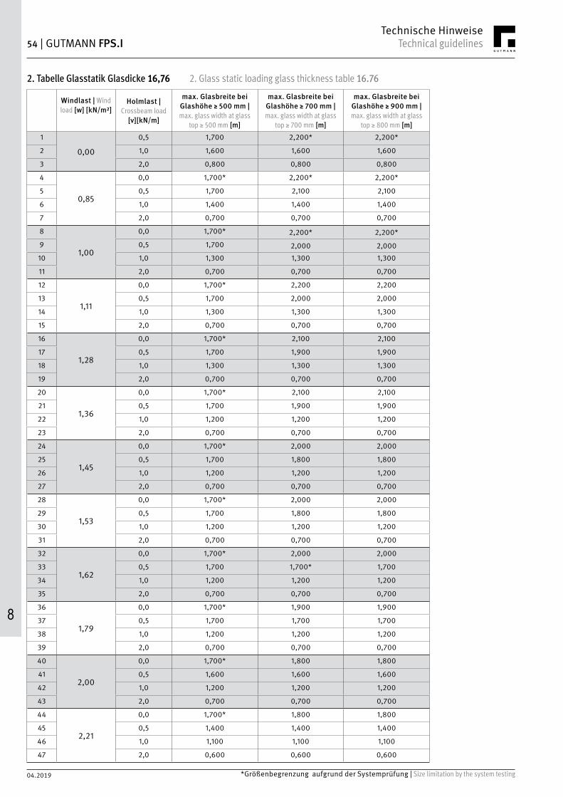
2. Glass static loading glass thickness table 16.762. Tabelle Glasstatik Glasdicke 16,76
Windlast | Wind load [w] [kN/m²]
Holmlast | Crossbeam load
[v][kN/m]
max. Glasbreite bei Glashöhe ≥ 500 mm |max. glass width at glass
top ≥ 500 mm [m]
max. Glasbreite bei Glashöhe ≥ 700 mm |max. glass width at glass
top ≥ 700 mm [m]
max. Glasbreite bei Glashöhe ≥ 900 mm |max. glass width at glass
top ≥ 800 mm [m]1
0,00
0,5 1,700 2,200* 2,200*
2 1,0 1,600 1,600 1,600
3 2,0 0,800 0,800 0,800
4
0,85
0,0 1,700* 2,200* 2,200*
5 0,5 1,700 2,100 2,100
6 1,0 1,400 1,400 1,400
7 2,0 0,700 0,700 0,700
8
1,00
0,0 1,700* 2,200* 2,200*9 0,5 1,700 2,000 2,00010 1,0 1,300 1,300 1,300
11 2,0 0,700 0,700 0,700
12
1,11
0,0 1,700* 2,200 2,200
13 0,5 1,700 2,000 2,000
14 1,0 1,300 1,300 1,300
15 2,0 0,700 0,700 0,700
16
1,28
0,0 1,700* 2,100 2,100
17 0,5 1,700 1,900 1,900
18 1,0 1,300 1,300 1,300
19 2,0 0,700 0,700 0,700
20
1,36
0,0 1,700* 2,100 2,100
21 0,5 1,700 1,900 1,900
22 1,0 1,200 1,200 1,200
23 2,0 0,700 0,700 0,700
24
1,45
0,0 1,700* 2,000 2,000
25 0,5 1,700 1,800 1,800
26 1,0 1,200 1,200 1,200
27 2,0 0,700 0,700 0,700
28
1,53
0,0 1,700* 2,000 2,000
29 0,5 1,700 1,800 1,800
30 1,0 1,200 1,200 1,200
31 2,0 0,700 0,700 0,700
32
1,62
0,0 1,700* 2,000 2,000
33 0,5 1,700 1,700* 1,700
34 1,0 1,200 1,200 1,200
35 2,0 0,700 0,700 0,700
36
1,79
0,0 1,700* 1,900 1,900
37 0,5 1,700 1,700 1,700
38 1,0 1,200 1,200 1,200
39 2,0 0,700 0,700 0,700
40
2,00
0,0 1,700* 1,800 1,800
41 0,5 1,600 1,600 1,600
42 1,0 1,200 1,200 1,200
43 2,0 0,700 0,700 0,700
44
2,21
0,0 1,700* 1,800 1,800
45 0,5 1,400 1,400 1,400
46 1,0 1,100 1,100 1,100
47 2,0 0,600 0,600 0,600
*Größenbegrenzung aufgrund der Systemprüfung | Size limitation by the system testing *Größenbegrenzung aufgrund der Systemprüfung | Size limitation by the system testing

04.2019
GUTMANN FPS.I | 55Technical guidelinesTechnische Hinweise
8
3. Glass static loading glass thickness table 20.763. Tabelle Glasstatik Glasdicke 20,76
Windlast | Wind load [w] [kN/m²]
Holmlast | Crossbeam load
[v][kN/m]
max. Glasbreite bei Glashöhe ≥ 350 mm |max. glass width at glass
top ≥ 350 mm [m]
max. Glasbreite bei Glashöhe ≥ 700 mm |max. glass width at glass
top ≥ 700 mm [m]
max. Glasbreite bei Glashöhe ≥ 900 mm |max. glass width at glass
top ≥ 900 mm [m]1
0,00
0,5 1,700 2,200* 2,200*
2 1,0 1,700 1,800 1,800
3 2,0 0,900 0,900 0,900
4
0,85
0,0 1,700* 2,200* 2,200*
5 0,5 1,700 2,200* 2,200*
6 1,0 1,500 1,500 1,500
7 2,0 0,800 0,800 0,800
8
1,00
0,0 1,700* 2,200* 2,200*9 0,5 1,700 2,200* 2,200*10 1,0 1,400 1,400 1,400
11 2,0 0,800 0,800 0,800
12
1,11
0,0 1,700* 2,200* 2,200*
13 0,5 1,700 2,200* 2,200*
14 1,0 1,400 1,400 1,400
15 2,0 0,800 0,800 0,800
16
1,28
0,0 1,700* 2,200* 2,200*17 0,5 1,700 2,100 2,100
18 1,0 1,400 1,400 1,400
19 2,0 0,700 0,700 0,700
20
1,36
0,0 1,700* 2,200* 2,200*
21 0,5 1,700 2,100 2,100
22 1,0 1,300 1,300 1,300
23 2,0 0,700 0,700 0,700
24
1,45
0,0 1,700* 2,200* 2,200*25 0,5 1,700 2,000 2,00026 1,0 1,300 1,300 1,300
27 2,0 0,700 0,700 0,700
28
1,53
0,0 1,700* 2,200* 2,200*
29 0,5 1,700 1,900 1,900
30 1,0 1,300 1,300 1,300
31 2,0 0,700 0,700 0,700
32
1,62
0,0 1,700* 2,200* 2,200*33 0,5 1,700 1,800 1,800
34 1,0 1,300 1,300 1,300
35 2,0 0,700 0,700 0,700
36
1,79
0,0 1,700* 2,200* 2,200*
37 0,5 1,700 1,700 1,700
38 1,0 1,200 1,200 1,200
39 2,0 0,700 0,700 0,700
40
2,00
0,0 1,700* 2,200* 2,200*41 0,5 1,600 1,600 1,600
42 1,0 1,200 1,200 1,200
43 2,0 0,700 0,700 0,700
44
2,21
0,0 1,700* 2,100 2,100
45 0,5 1,500 1,500 1,500
46 1,0 1,100 1,100 1,100
47 2,0 0,700 0,700 0,700
*Größenbegrenzung aufgrund der Systemprüfung | Size limitation by the system testing

8
04.2019
56 | GUTMANN FPS.I Technical guidelinesTechnische Hinweise
HolzteilFür die Qualität des Holzes gilt DIN 68360 Teil 1 „Holz für Tischlerarbei-ten; Gütebedingungen bei Außenanwendungen“. Der maximale Wert des Feuchtigkeitsgehaltes der Einzelteile darf 15 % nicht übersteigen. Der Streubereich des Feuchtigkeitsgehaltes darf allgemein nicht größer sein als 4 % und bei Verwendung von Keilzinken als Längsverbindung sowie bei Verwendung von lamellierten Querschnitten nicht größer als 2 %. Die Messung des Feuchtigkeitsgehaltes ist vor Beginn der form-gebenden Verarbeitung durchzuführen und aktenkundig zu erfassen.
Profilausbildung – HolzDie Profilausbildung ist in Anlehnung an DIN 68121 „Holzfenster- und -türenprofile“ und DIN 18361 „Verglasungsarbeiten“ vorzunehmen. Rahmenverbindung Holzprofile: Die Rahmenverbindungen sind mit Schlitz/Zapfen auszuführen. Alle Rahmenverbindungen ab einer Holzdicke von 45 mm sind mindestens mit Doppelzapfen auszuführen; die äußeren Wangen dürfen dabei nicht dicker als ca. 16 mm sein.
Oberflächenschutz – HolzFür den Holzschutz gilt DIN 68805. Als Holzschutzmittel sind nur solche Mittel anzuwenden, deren Anstrichverträglichkeit nachgewiesen sind. Das Anstrichmittel muss DIN 18363 und den „Technischen Richtlinien für Fensteranstriche“ entsprechen.
Perfekte Systemprofile von GUTMANN für den FensterbauerGUTMANN Aluminium Systemprofile für die Holzindustrie werden in enger Zusammenarbeit mit dem Institut für Fenstertechnik in Rosen-heim sowie den Fenster-, Beschläge- und Fräswerkzeugherstellern entwickelt. Die auf GUTMANN Systemprofile genau abgestimm-ten Werkzeuge für Holz-Fenster und -Türen liefern u. a. folgende Hersteller von Fräswerkzeugen.
Aluminium-StrangpressprofileNachdem es 1886 gelungen war, Aluminium mit Hilfe der Schmelz-flusselektrolyse in großtechnischem Maßstab herzustellen, hat sich dieser Werkstoff rasch zu einem der wichtigsten Ge-brauchsmetalle entwickelt. Aufgrund des geringen Gewichtes, der dekorativen oberflächenbehandlung, der leichten Bearbeit-barkeit und der enormen Witterungsbeständigkeit hat Alumi-nium gerade im Baubereich eine große Bedeutung erlangt.
Das Strangpressen von Aluminium-Werkstoffen ermöglicht – wie keine andere Halbzeugfertigung – die Herstellung vielfältigster Formen, vom einfachen Vollprofil bis zum komplizierten Hohlprofil.
Beim Strangpressen ist das Werkzeug (Matrize) fest eingespannt. Der Pressstempel mit vorgesetzter Pressscheibe drückt den ange-wärmten Pressbolzen gegen den Werkzeugsatz, der den Rezipienten an der Austrittseite verschließt und staucht den Pressbolzen gegen die Rezipienten-Innenwand. Dann beginnt das Austreten des Press-stranges in gleicher Richtung wie die Stempelvorwärtsbewegung.
Legierung der Aluminiumprofile: EN AW 6060 T 66 (AlMgSi 0,5 F 22)
GUTMANN System Profile entsprechen der DIN EN 12020 bzw. DIN EN 755.
Was Sie noch wissen solltenWir empfehlen dringend, die Profile und Zubehörteile vor dem Einbau genau zu überprüfen. Wir weisen darauf hin, dass eine Haftung auf die Höhe des Warenwertes der Profile und des Zubehörs begrenzt ist. Dies gilt insbesondere für Kosten und Schäden, die bei einem evtl. erforderlichen Austausch beim Ausbau und ggf. Neueinbau entstehen. Dies gilt ferner für Sachschäden nach §§ 823 ff BGB und Gewährleistungsansprüche infolge Material- und Konstruktionsfeh-lern, Instruktionsfehler, Bearbeitungs- und Einbaufehler sowie für mittelbare Schäden. Gesetzliche Ansprüche bleiben unberührt.
Aluminium-Bausysteme von GUTMANNDurch die Herausgabe dieses Kataloges werden alle früheren Unter-lagen ungültig. Alle Abbildungen entsprechen dem neuesten Stand (Maßstab 1:1). Änderungen im Rahmen des technischen Fortschrittes behalten wir uns vor. Für Artikel, die aus früheren Unterlagen nicht mehr übernommen wur-den, ist die Serienfertigung eingestellt. Sie sind zum Teil noch lieferbar. Liefermöglichkeiten sind auf Anfrage erhältlich. Für Druckfehler und andere Irrtümer übernehmen wir keine Haftung. Die Lieferung erfolgt nur über den Fachhandel.

04.2019
GUTMANN FPS.I | 57Technical guidelinesTechnische Hinweise
8
Wooden partDIN 68360 Part 1 “Wood for Carpentry; Quality Requirements for Exterior Applica-tion” must be consulted when choosing the quality of the wood. The maximum moisture percentage of the individual parts may not exceed 15%. The scatter of the moisture percentage may not exceed 4% in general and may not exceed 2% when us-ing wedge-shaped prongs as a splice or when using laminated cross sections. Mois-ture percentage must be recorded and measured before any shaping work begins.
Profile formation – WoodThe formation of profiles must follow DIN 68121 “Timber Profiles for Windows and Doors” as well as DIN 18361 “Glazing Works”. Wood profile frame con-nection The frame connections must be realized with tongues and grooves. All frame connections thicker than 45 mm must be realized at least with dou-ble tongues; the outer frame thickness may not exceed approx. 16 mm.
Surface protection – WoodDIN 68805 applies to wood protection. only wood preservatives with proven coating compatibility are to be used. Liquid coating materials must follow DIN 18363 and the “Technical Guidelines for Window Coating”.
Perfect system profiles for window builders from GUTMANNGUTMANN aluminium system profiles for the wood industry are developed in close collaboration with the IFT Rosenheim (Institute for Window Engineering) as well as window, fitting, and milling tool manufacturers. The tools for wood windows and doors closely coordinated with the GUTMANN system profiles are delivered by some of the following milling tool manufacturers.
Extruded aluminium profilesAfter aluminium could finally be produced on a large scale by means of fusion elec-trolysis in 1886, the material quickly became one of the most important utility met-als. The low weight, decorative surface, easy workability and outstanding weather resistance have made aluminium very significant for the building industry. Like no other semi-product manufacturing, aluminium extrusion has facilitated the production of an enormous variety of shapes, from simple solid profiles to compli-cated hollow profiles. During extrusion the tool (mold) is clamped tightly. The extrusion die with a pro-jected disk pushes the heated ram against the tooling, which closes off the recipient at the exit and forces the ram against the inner recipient wall. The extruded profile then exits in the same forward direction as the extrusion die.
Aluminium profiles - Alloy:EN AW 6060 T 66 (AlMgSi 0.5 F 22)
GUTMANN system profiles follow DIN EN 12020 as well as DIN EN 755.
Final notesWe urge you to examine the profiles and accessories very closely before installing them. We would like to stress that liability is limited to the monetary value of the profiles and accessories. This especially applies to costs and damage caused during possible disassembly and reassembly. It furthermore applies to property damage according to Section 823 ff of the German Civil Code and warranty claims as a result of material defects, constructional faults, faulty instruction, fashioning defects, installation errors, as well as consequential damages. Legal claims remain unaffected.
GUTMANN aluminium construction systemsThe release of this catalog renders all previous editions invalid. All illustrations are up to date (1:1 scale). We reserve the right to make modifications in the event of technological progress. Volume production has ceased for items discontinued from previous editions of this catalog. They may, however, still be in stock. Delivery options for those items are available upon request. We do not assume liability for misprints and other errors. Delivery only from specialty stores.

8
04.2019
58 | GUTMANN FPS.I Technical guidelinesTechnische Hinweise
Pulverbeschichten von AluminiumDurch das Pulverbeschichten von Aluminiumprofilen kann jedem Farbwunsch nach der RAL-Karte Rechnung getragen werden. Gerade für die dekorative Verwendung in der Außenarchitektur bietet sich die breite Farbpalette an.
Die elektrostatische Pulverbeschichtung ist ein relativ junges, aber bewährtes Lackierverfahren, welches dekorative und wertbeständige sowie dauerhafte Oberflächen erzeugt.
Die Pulverbeschichtung unserer Aluminiumprofile wird von Partnerfirmen Durchgeführt die der "Internationalen Gütergemeinschaft für die Stückbeschichtung von Bauteilen - GSB" angeschlossen sind.
Verbindlichkeit hinsichtlich Farbton und Glanz können aus dem GUTMANN-Farbfächer nicht abgeleitet werden, da Farbunterschiede zu den Originalfarben aufgrund unterschiedlicher Herstellungs-verfahren und Pigmentirung nicht ausgeschlossen sind.Der GUTMANN-Farbfächer dient deshalb nur zur orientieren-den Übersicht und ist nicht als Produktionsvorlage geeignet.
Zur besonderen BeachtungPulverlacke in ihrem Farbton, wie alle anderen Lacke und Farben sind fertiggunstechnischen Toleranzen und Schwankungen unterworfen.
Ebenso kann davon ausgegangen werden, dass RAL-Farbtöne, die von unterschiedlichen Beschichtern stammen, in der Regel nicht optisch übereinstimmen, da meist Pulverlacke unterschiedlicher Hersteller verwendet werden.
Das bedeutet, dass seitens des Kunden unbedingt darauf geachtet werden muss, dass sämtliche Bauteile, die nebeneinander am Gebäude ingebaut werden, gleichzeitig in einer Charge zu beauftragen sind. Ist dies nicht möglich, sind unbedingt besondere Absprachen mit unseren Mitarbeitern zu treffen.
In puncto Nachfolgewerke bedarf es diesbezüglich generell einer separaten Abstimmung.
Zudem kann es insbesondere bei Metallicfarben - wie z.B. RAL 9006, RAL 9007 sowie den DB-Oberflächen 701, 702, 703 etc., bedingt durch die verschiedenen physikalischen Gegebenheiten bei der elek-trostatischen Applikation dieser Pulverlacke vorkommen, dass Unterschiede im Erscheinungsbild dieser Oberfläche auftreten.
Kontaktstellen bei EloxalbeschichtungAn den Enden von eloxierten Aluminiumprofilen kommt es im Bereich von ca. 50 mm zu Kontaktstellen, die nicht für Sichtflächen geeignet sind.
Filiformkorrosion und VoranodisationIm küstennahen Bereich bis zu einer Entfernung von 30 km zum Meer können bei pulverbeschichteten Bauteilen Schädigungen durch Filiformkorrosion auftreten. Zur Vermeidung der Filiformkorrosion wird empfohlen, statt der herkömmlichen Vorbehandlung (Chro-matieren) eine Voranodisation durchzuführen, die dann ausdrück-lich in der Anfrage und der Bestellung gefordert werden muss.
Transport-/Schutzfolie bei veredelten Profiloberflächen:Die bei Stangenware und mechanisch konfektionierten Metallprofilrah-men zum Schutz der veredelten Profiloberfläche aufgeklebte Schutzfolie ist nicht UV-beständig. Sonneneinstrahlung während der Lagerung ist zu vermeiden. Die Folie ist sofort nach Montage der Metallprofile auf der Fassadenkonstruktion bzw. des Metall-profilrahmens auf dem Fensterelement zu entfernen!
Powder Coating AluminiumAluminium profiles may be powder coated in any color on the RAL chart. This board selection of colors is especially useful for decorative purpses in outdoor architecture.
Electrostatic powder coating is a rather young yet proven lacquering method, which produces decorative, consistent, and long-lasting surfaces.
Our aluminium profiles are powder coated by partner companies, which all follow the "Guidelines for the Piecework of Coating Building Componens by GSB-International"
.
The exact shade and luster from GUTMANN color chart may not be guaranteed as different color outcome. Therefore the GUTMANN color chart should not be used as a model for production but rather as an overview.
Important NoticePowder paints, like all other lacquers and paints, are subject to product tolerances and variations.
In the same way, RAL colors from different coating plants do generally not look exactly alike since the plants procure powder paints from different manufacturers.
This means that customers must order all compnents to be placed next to one another on the building in one charge. If this is not possible, be sure to make special arrangements with one of our employees.
Subsequent works must be arranged separately as well.
Different physical conditions in electrostatic application of powder paints may make the surfaces appear different, especially those of metal paints such as RAL 9006, RAL 9007 and DB surface 701, 702, 703, and so on.
Contact points dor anodizingThe ends of anodized aluminium profiles from contact points within 50 mm, which are not suitable for face sides.
Filiform corrosion and pre-anodizationStructural components may suffer damage from filliform corrosion in coastal areas up to 30 km from the ocean. In order to avoid filliform corrosion, it is recommended to pre-anodize instead of the typical pretreating (chromating) This must be indicated separately in inquiries and orders.
Transport -/Protective foil for processed profile surfaces:The foil put on the processed profile surfaces (simple profiles or frames) is not resistant to UV radiation. Avoid putting profiles in the sunlight when being stocked. The foil is to be pulled away from the profiles immediately after the profiles or the frames have been mounted on the fassade.

04.2019
GUTMANN FPS.I | 59Technical guidelinesTechnische Hinweise
8
Montageanweisungen für Aluminium und Systemzubehör
Aluminium ist eines der edelsten und dekorativsten Metalle, die in der Baubranche Verwendung finden. Entsprechend sorgfältig ist bei der Montage von Aluminiumteilen auf die folgenden Hinweise zu achten. Die Montage und Bauandichtung der Aluminium-Systemprofile von GUTMANN sollte nach den „Richtlinien der RAL-Gütesicherung Montage" erfolgen.
Oberflächenschutz Aluminiumbauteile dürfen Kratz- und Stoßbeanspruchungen nicht ausgesetzt werden. Ihr Einbau sollte erst nach Beendigung der Mauer-, Stuck- und Putz- sowie Werkstein- und Plattenarbeiten erfolgen, um eine Einwirkung von z.B. Kalk- und Zementspritzern auf die Oberfläche zu vermeiden.Verunreinigungen durch alkalische Substanzen müssen sofort entfernt werden, da Schäden an der Baustelle meistens nicht mehr behoben werden können. Werden Mauer- und Putzarbeiten erst nach dem Einbau der anodisch oxidierten oder beschichteten Aluminium-Bauteile durchgeführt, sind diese zum Schutz vor Beschädigung und Verschmutzung durch Baumaterialien mit dazu geeigneten selbsthaftenden, UV-beständigen Kunststoff-Folien abzudecken. Die Schutzfolie ist vor der Auslieferung anzubringen, da diese zusätzlich vor Transportschäden schützt.
Materialverträglichkeit GUTMANN Systemprofile werden wetterbeständig und dauerhaft be-schichtet. Das Systemzubehör wird aus hochwertigen Materialien hergestellt. GUTMANN Systeme können daher problemlos mit vielen Materialien verbaut werden, die bei der Montage am Bau zur Anwen-dung kommen. Bei Einsatz von Substanzen, die üblicherweise keinen Kontakt zu GUTMANN Systemprofilen oder -zubehör haben, ist die Verträglichkeit vorab zu prüfen.
Metalle wie Blei, Kupfer oder kupferhaltige Legierungen (z. B. Messing) dürfen nicht zusammen mit Aluminium eingebaut werden (auch nicht im Flüssigkeitsbereich). Bauteile aus Edelstahl können mit Aluminium problemlos verarbeitet werden.
Befestigung Die Befestigung von Aluminiumprofilen (z. B. Rolladenprofile, Metallfensterbänke, Regenschutzschienen) muss grundsätzlich mit Schrauben aus Edelstahl V2A vor- genommen werden.
Längenausdehnung Da Aluminium ein anderes Ausdehnungsverhalten hat, sollte keine feste Einbindung in Putz oder Baukörper vorgenommen werden. Die Befestigung zwischen Aluminium und Baukörper sollte grundsätzlich gleitend ausgebildet sein. Die Längenänderung beträgt ca. 1,2 mm/m bei 50 ° Temperaturunterschied.
Längen über 3000 mm sollten nicht ohne Stoßverbindung (Dehnungsfuge) eingebaut werden.
Assembly instructions for aluminium and system accessories
Aluminium is one of the most precious and decorative metals used in construction. Therefore the following guidelines must be observed when installing aluminium components: Installation and sealing of GUTMANN aluminium system profiles should follow the "RAL Quality Assurance Guidelines for Installation".
Surface Protection Aluminium components must not be exposed to scratching or impact stresses. The components should only be installed after all bricklaying, stucco decoration, plastering, natural stone work, and stone flooring is completed so that the surface remains free of lime or cement splatter. Contamination by alkaline substances must be removed immediately as this type of damage can often not be repaired on site.
If brickwork and plastering are completed after installing anodized or color coated aluminium components, the components must be protected from damage and soiling with construction material by applying appropriate self-adhesive UV-resistant plastic foils. The protective foil must be applied before delivery of the item as it serves as additional protection from transport damage. Compatibility of MaterialGUTMANN system profiles are weatherproof and permanently coated. System accessories are made from high-quality materials. GUTMANN systems therefore work well with many materials commonly used in construction. When introducing substances not normally related to GUTMANN system profiles or accessories, compatibility must be tested beforehand.
Metals such as lead, copper, or cupreous alloys (e.g. brass) must not be installed together with aluminium (not in liquid state either). Stainless-steel elements may be processed together with aluminium without a problem.
Fastening Aluminium profiles (such as rolling shutter profiles, metal window sills, and weather bars) must always be fastened with V2A stainless-steel screws.
Linear Extension Due to differing linear extension, aluminium should not be directly incorporated into the plaster or structure. Connections of aluminium and building structure should always be gliding. At a temperature difference of 50 °C, linear extension amounts to 1.2 mm/m.
Lengths of over 3000 mm should not be installed without expansion joints.

04.2019
60 | GUTMANN FPS.I Care and maintenancePflege und Wartung
Sie haben ein hochwertiges Qualitätsprodukt mit absturzhemmenden Eigen-schaften erhalten. Der französische Balkon wurde unter den Gesichtspunkten Sicherheit, Langlebigkeit und Design entwickelt. Die Funktion und Sicherheit dieses Produktes ist nur bei richtiger Nutzung, Wartung und Pflege gewährleistet.
[A] Nutzung
Der französische Balkon ist eine Sicherheitseinrichtung, die gegen Absturz sichern soll. Er ist keinesfalls eine Sitzgelegenheit oder Haltevorrichtung für Blumenkästen o.Ä.
Sicherheitshinweise
Bei der Reinigung der äußeren Glasfläche besteht evtl. Ab-sturzgefahr! Deswegen beim Putzen der Glasaußenfläche z.B. Abzieher mit langem Stil und ggf. Sicherheitsgeschir-re nutzen oder andere Sicherheitsvorkehrungen treffen![B] PflegeSichern Sie die Funktion Ihres französischen Bal-kons dauerhaft! Ihr französischer Balkon benötigt eine regelmäßige Inspektion und Wartung. Gewalteinwirkung auf das Produkt führt zu Schäden und ist zu vermeiden. Sollten Sie während der Nutzung Unregel-mäßigkeiten feststellen, ziehen Sie gegebenenfalls einen Fachmann hinzu. Erfragen und beachten Sie die vorgeschrie-benen Intervalle. Achten Sie dabei grundsätzlich auf:
Pflege der außenseitigen Alu-Oberflächen mit geeigneten Reinigungsmitteln (Regelpflegeintervall: jährlich)
Verwenden Sie einen weichen Schwamm und viel Wasser unter Zusatz eines neutralen Netzmittels. Zugelassene Reinigungsmit-tel erhalten Sie bei GUTMANN. Keinesfalls geeignet sind stark abrasive oder lösungsmittelhaltige Substanzen. (Vergleiche auch hierzu: Merkblatt A5 der Aluminium-Zentrale, Düsseldorf) Verwen-den Sie zur Reinigung keine scharfen oder spitzen Gegenstände.Pflege der Verglasung
Das nachträgliche Aufbringen von absorbierenden Folien und Farben führt bei Sonneneinstrahlung zu einer starken thermischen Belastung der Gläser mit der Gefahr eines thermisch induzierten Scheiben-bruchs. Eine erhöhte thermische Belastung wird für ein Glas auch erzeugt, wenn ein Teil der Scheibe der direkten Sonne ausgesetzt ist, während ein anderer Teil im Schatten liegt. Solche teilbeschat-teten Gläser werden ungleichmäßig erwärmt und es besteht auch hier die Möglichkeit des thermisch induzierten Scheibenbruchs.Aufkleber und Etiketten auf den Gläsern sind mit einem für diesen Zweck besonders geeigneten Spezialkleber versehen. Sie sollten aber schnellstmöglich von den Glasscheiben entfernt wer-den. Insbesondere sollten die Aufkleber nicht für längere Zeit der Sonneneinstrahlung ausgesetzt sein. Nicht völlig vermeidbar ist ein gegenüber dem Rest der Glasoberfläche anderes Benetzungsverhalten an den Stellen, an denen Aufkleber und Etiketten entfernt wurden.
You have chosen a high quality product with fall prevention properties. The French balcony was designed with safety, longevity and design in mind. The function and safety of this product is guaranteed only when used, maintained and cared for properly.
[A] Usage
The French balcony is a safety device intended to protect against falling. It is by no means a seat or holding device for flower boxes or similar.
Safety instructions
When cleaning the outer glass surface, there may be a risk of falling! Therefore, when cleaning the glass outer surface, use for instance squeegees with a long handle and, if necessary, safety harnesses or other safety precautions![B] CareEnsure the proper function of your French balcony at all times! Your French balcony requires regular inspection and maintenance. Excessive force on the product will cause damage and must be avoided. If you notice any irregularities during use, consult a specialist if necessary. Ask about and observe the prescribed intervals. In doing so, always ensure the following:
Servicing of the outer aluminium surfaces with suitable cleaning agents (standard servicing interval: yearly)
Use a soft sponge and plenty of water with the addition of a neutral moistening agent. You can purchase approved cleaning agents from GUTMANN. Highly abrasive substances or those containing solvents are by no means suitable. (please also refer to: Leaflet A5 from "Aluminium-Zentrale", Düs-seldorf) Do not use sharp or pointed objects for cleaning.Care of the glazing
The subsequent application of absorbent films and colours leads to a strong thermal load of the glass in sunlight with the risk of thermally induced pane breakage. An increased thermal load is also generated for a pane of glass when one part of the pane is exposed to direct sun while another part is in shadow. Such par-tially shaded glass panes are heated unevenly and there is also the possibility of thermally induced pane breakage here.Stickers and labels on the glass panes are provided with a special adhesive suitable for this purpose. But they should be removed from the glass as quickly as possible. In particular, the stickers should not be exposed to the sun for a long time. Different mois-tening behaviour compared to the rest of the glass surface at the places where stickers and labels were removed cannot be com-pletely avoided. Cork stoppers can also leave residues on glass surfaces or change the moistening behaviour of the glass surfaces. They must therefore also be removed as soon as possible.
!auf Veränderungen achten
Pay attention to any changes
Dichtungen prüfenCheck gaskets
Lockere Teile befestigenSecure loose parts

04.2019
FPS.I | 61Care and maintenancePflege und Wartung
Auch Korkstapelscheiben können Rückstände auf Glasoberflächen hinterlassen oder das Benetzungsverhalten der Glasoberflächen verändern. Sie sind deshalb ebenfalls schnellstmöglich zu entfernen.Bei der Reinigung von Glas ist viel und möglichst saube-res Wasser zu verwenden, um einen Scheuereffekt durch Schmutzpartikel zu vermeiden. Auf keinen Fall die Dichtungs-oberflächen „sauber rubbeln“, sondern abgelagerte Verun-reinigungen ebenfalls mit reichlich Wasser abspülen.Als Handwerkszeuge sind zum Beispiel weiche, saubere Schwämme, Leder, Lappen oder Gummiabstreifer geeignet. Unterstützt werden kann die Reinigungswirkung durch den Einsatz neutraler Reinigungs-mittel oder handelsüblicher Haushalts-Glasreiniger. Handelt es sich bei den Verschmutzungen um Fett oder Dichtstoffrückstände, so kann für die Reinigung auf handelsübliche Lösungsmittel wie Spiritus oder Isopropanol zurückgegriffen werden. Von allen chemischen Reinigungs-mitteln dürfen alkalische Laugen, Säuren und fluoridhaltige Mittel generell nicht angewendet werden. Der Einsatz von spitzen / scharfen metallischen Gegenständen, z. B. Klingen oder Messern, kann Oberflä-chenschäden (Kratzer) verursachen. Das sogenannte „Abklingen“ mit dem Glashobel zur Reinigung ganzer Glasflächen ist nicht zulässig.
Schutz während der Bauphase (in der gesamten Bauzeit)
Schützen Sie Ihre Fenster mit geeigneten Maßnahmen vor Verschmut-zung und Beschädigung während der Bauzeit. Metallteile, Rahmen oder Kunststoffoberflächen sind häufig durch eine Folie werkseitig geschützt, die nach dem Ende der Montagearbeiten zu entfernen ist. Alle Fenster sind bei Mörtel- und Putzarbeiten bauseits mit Folie abzudecken; diese ist mit geeigneten Klebebänder, wie z. B. Tesa 4438 oder 4838, zu befestigen (im Zweifelsfall beim Fensterherstel-ler nachfragen). Die Bänder müssen sich rückstandslos abziehen lassen und dürfen dabei eine Holzfensterlackierung nicht beschä-digen. Folien und Klebebänder sind so bald wie möglich, spätes-tens jedoch nach 2 Wochen, wieder zu entfernen! Sollte es durch Putz- oder Mörtelreste zu Verunreinigungen gekommen sein, so ist der Rahmen umgehend mit viel Wasser, einem neutralen Allzweck-reiniger (ohne aggressive Stoffe, Lösungs- oder Scheuermittel) und einem weichen Schwammtuch zu säubern. Von den Glasflächen sind Putz- oder Mörtelreste sofort mit viel Wasser abzuspülen! Aufkle-ber und Kleberreste mit warmer Seifenlauge und einem Schwamm oder mit einem Kunststoffspachtel vorsichtig ablösen - keine Rasierklingen, Stahlspachtel oder Scheuermittel einsetzen!Bei Arbeiten mit Winkelschleifern, Sandstrahlgeräten oder Schweiß-brennern müssen Glas- und Rahmenoberflächen vor möglichen Oberflächenschäden durch Funkenaufschlag geschützt werden. Bei Arbeiten in Scheibennähe sind die Oberflächen gegen Kratzer, Spritzer, Dämpfe, Schweißnebel oder starke Wärmeentwicklung (Heißasphaltarbeiten) zu schützen.[C] Wartungsarbeiten
Fenster und Türen werden tagtäglich benutzt und dabei je nach Einsatzort (Wohnhaus, Hotel, Schule) mehr oder weniger stark strapaziert. Zusätzlich sind sie wechselnden Witterungsbedingun-gen wie Sonne, Regen, Schnee und Wind ausgesetzt. Deswegen bedürfen Fenster und Türen, sowie daran befestigte Absturzsi-cherungen der regelmäßigen Pflege, Wartung und Instandhaltung – und das auch schon innerhalb der Gewährleistungsfristen! Die Instandhaltung aller baulichen Anlagen und Einrichtungen wird im Übrigen auch durch die Bauordnungen der Länder gesetzlich gefordert. Folgende zeitliche Intervalle werden empfohlen:
When cleaning glass, use a lot of water that is as clean as possible to avoid a scrubbing effect caused by dirt particles. Under no circumstances are the sealing surfaces to be "rubbed clean". Instead, rinse off contaminants with plenty of water.For example, soft, clean sponges, leather, cloths or rubber scrapers are suitable tools. The cleaning effect can be aided by the use of neutral detergent or commercial household glass cleaner. If the conta-minants are grease or sealant residues, it is possible to resort to commercial solvents such as spirit or isopropanol for cleaning. Of all chemical cleaning agents, alkaline solutions, acids and fluoride-containing agents should generally not be used. The use of sharp / pointed metallic objects, e.g. blades or knives may cause surface damage (scratches). Scraping clean with a glass blade for cleaning entire glass surfaces is not allowed.
Protection during the construction phase (throughout the construction period)
Protect your windows against pollution and damage during construc-tion with suitable measures. Metal parts, frames or plastic surfaces are often factory-protected by a film, which must be removed after the end of the assembly work. All windows must be covered with film during mortar and plaster work; this must be secured with suitable tapes, for instance such as Tesa 4438 or 4838 (in case of doubt ask the window manufacturer). The tapes must be able to be removed without residue and must not damage a wood window finish. Films and adhesive tapes must be removed as soon as possible, but no later than after 2 weeks! Should there be any impurities due to plaster or mortar residues, clean the frame immediately with plenty of water, a neutral all-purpose clea-ner (without aggressive substances, solvents or abrasives) and a soft sponge cloth. Rinse plaster or mortar residues off the glass surfaces with plenty of water immediately! Carefully peel off stickers and ad-hesive residues with warm soapy water and a sponge or with a plastic spatula - do not use razor blades, steel spatulas or scouring agents!When working with angle grinders, sandblasting equipment or welding torches, glass and frame surfaces must be protected against possible surface damage due to sparking. When working near the window, the surfaces must be protected against scratches, splashes, vapours, welding fog or excessive heat generation (hot asphalt work).
[C] Maintenance work
Windows and doors are used on a daily basis and depending on the location (home, hotel, school) or varying degrees of wear and tear. In addition, they are exposed to changing weather con-ditions such as sun, rain, snow and wind. That's why windows and doors, as well as attached safety barriers, require regular care, maintenance and servicing - even within the warranty peri-od! Incidentally, the maintenance of all structures and facilities is also legally required by the building regulations of the German federal states. The following intervals are recommended:
Sicherheitsrelevante Inspektionsintervalle der Absturzsicherung /Safety-relevant inspection intervals of fall protection equipmentSchul- und Hotelbauten / School and hotel buildings halbjährlich / Every six months
Büros und öffentliche Gebäude / Offices and public buildings halbjährlich bis jährlich / Every six to twelve months
Privater Wohnungsbau / Private housing ein- bis zweijährlich / Every one to two years

221
GUT�ANN MIRA NotesNotizen
NOTIZEN NOTES

A LU M I N I U M S H A P E D BY G U T M A N N
Möglichkeiten der OberflächengestaltungAvailable Colors for Surface Design
Die richtige Farbauswahl ist somit ein entscheidendes Kriterium bei
der Gestaltung von Gebäuden. GUTMANN bietet Ihnen unzählige
Kombinations- und Variationsmöglichkeiten. Sämtliche Farben
nach RAL, NCS, Dekor- und Sonderfarben sind erhältlich. Auf diese
Weise lassen sich Fenster, Türen und Fassaden farblich exakt auf die
Umgebung abstimmen.
Choosing the right colors is, therefore, an important factor in
designing residential buildings. GUTMANN off ers countless options
for combination and variation. All RAL, NCS, decorative or special
colors are available. This allows windows, doors, and curtain walls
to perfectly match their environment in color.
Farben und Formen bilden eine harmonische Einheit. Die Farbgebung
unterstützt die Form und bringt sie besonders gut zur Geltung. Im
Gegenzug dazu wird durch eine gelungene Form die Wirkung der
Farbe unterstrichen und hervorgehoben.
Colors and shapes form a harmonious unit together. The choice of
colors can reinforce and accentuate the shapes. At the same time,
appealing shapes can emphasize and bring out the eff ect of the
colors.
Aus drucktechnischen Gründen sind die abgebildeten Farben nicht verbindlich. Bitte bestellen Sie unseren GUTMANN EXCLUSIV Farbfächer.For technical reasons, the colors shown are not authoritative. Please order our GUTMANN EXCLUSIV color fan deck.
→ RAL Standardfarben und DB Farben | Standard RAL and DB colors,
gemäß GUTMANN Farbfächer | referred to GUTMANN fan deck
→ Decoralfarben/Holzdekore | Decoral colors/Wood look
→ Eloxalfarben | Anodised colors
→ AOC Farben (nachgestellte Eloxalfarben, beschichtet) |
AOC colors (simulated anodised colors, coated)
→ Mikrolierte Oberflächen | Micro-polished surfaces
→ Trendfarben | Trend colors
→ PREMIUM Farben | PREMIUM colors
Hochwertige Farbauswahl in unserem GUTMANN EXCLUSIV Farbfächer.High-quality color selections can be seen in our GUTMANN EXCLUSIV fan deck.
© Adobe Stock

GUT�ANN Bausysteme GmbHNuernberger Str. 57 | 91781 Weissenburg, GermanyT +49 (0) 9141-995 11 36 | F +49 (0) 9141-995 11 37www.gutmann-bausysteme.de | [email protected]
GUT�ANN ALUSWISS AG – SwitzerlandChaltenboden Str. 16 | 8834 Schindellegi, SwitzerlandT +41 (0) 58-310-1210 | F +41 (0) 58-310-1211www.gutmann-aluswiss.com | [email protected]
GUT�ANN Middle East LLCDubai Investment Park 1 P.O. Box 54563 | Dubai, United Arab EmiratesT +971 (4) 88 5333-6 | F +971 (4) 88 5333-9www.gutmann.ae | [email protected]
gutmann-bausysteme.de 1/30
00/0
4.19
/GUT
MAN
N/Fr
ank/
7821
9/de
_en