Embed Size (px)
Citation preview

SUSQUEHANNA STEAM ELECTRIC STATION
REPORT
DP/ESTIGATION OF UNIT ONE
SMALL PIPING SYSTEM DESIGN
INSTALLATION Ai%) INSPECTION
PROGRAM ADEQUACY AND IMPLEMENTATION
f . H. GulliverInvestigation Team Leader
B. . oyerInvestigation Team Leader
R. J. Shovlinnvestigation Manager
82p9Zpp+87 9pp908
9

SUSQUEHANNA STEAM ELECTRIC STATION — UNIT 1
REPORT — INV/ESTIGATION OF SMALL PIPING SYSTEM DESIGNINSTALLATIONAND INSPECTION — PROGiU48 ADEQUACY
AND IMPLEMENTATIONAUGUST 3 — 12, 1982
I. INVESTIGATION OBJECTIVES
The ultimate objective is to ensure Pennsylvania Power 5 LightCompany that recently encountered problems in the design, installa-
~tion and inspection of small pipe'ystems do not pose a threat to thesafe and reliable operation of Susquehanna Steam Electric Station.
In support of the ultimate objective, there are several principleobjectives:
A. To assess the adequacy of small pipe design/installation/in-spection programs and their implementation for a representativesample.
B. To document inadequacies (in the form of Findings andObsezvations).
C. To address the program implications of specific concerns raisedby the NRC, and in the allegation letter dated May 3, 1982.
D. To transmit all Findings/Observations (defined in Section III ofthis report) to the independent Rev"ew Committee with an assess-ment of broader implications for other design/installation/in-spection activities.
II. CONDUCT OF THE INVESTIGATION
The conduct of the Investigation was handled in accordance withNuclear Quality Assurance Procedures 9.1 and 19.0 to the extent thatPlans, Checklists and Findings/Observations were documented and afull Investigation Report was to be developed.
Two Investigat-on Teams were assembled. Their responsibilities were:
A. Investi ation Team //1
The primary responsibility of Investigation Team //1 was thedesign/installation program. They reviewed all relevant docu-ments, specifications, and procedures, and a representativepiping system to determine:

1. How the original/revised design intent was developed anddocumented.
2. The format for conveying design intent, verifying itsimplementation and evaluating the functionality of as-builtdesigns.
3. If the individual Design and Installation Program/Pro-cedures were unique and exclusive to each function, or werethey complementary?
4. The impact of a transfer of certain design responsibilitiesto various field organizations.
5. The strength and weaknesses of the Design/InstallationPrograms.
Investigation Team 82
The primary responsibility of Investigation Team 82 was theInspection Program. They reviewed all relevant documents,specifications, procedures, a representative piping system, andthe Bechtel and the PPSL Inspection funct'ons to determine:
l. If the Bechtel Inspection program is complementary to theD'esign/Installation Program.
2. If the Bechtel Inspection Program provides adequate feed-back to the Design/Installation organizations to assurehardware implementation in accordance with design intent.
3. If the Bechtel Inspection functions'esponsibility toverify "as-built" documentation is adequate and provides afeedback loop in the design verification process.
4. To determine if there are appropriate interfaces estab-lished between the Bechtel and PPKL Inspection functions.
5. The extent to which the Bechtel and PPSL Inspection func-tions are responsible to verify the functionality ofhardware as installed.
6. The strength and weaknesses of the Inspection Programs.
Pinin System Nalkdown
Coincident with the "Invesrigations, two representative smallpipe systems were selected'or, walkdown. The InvestigationTeams „"'ointly developed a'alkdown plan to verify that the
I
'7

design intent was implemented in the specific hardware of thosesystems.
D. Processin of Investi ation Team Findin s
When either of the Investigation Teams developed Findings duringtheir investigation, those Findings were to be forwarded immedi-ately to the Investigations Hanager, who was in turn responsibleto:
Immediately inform the Plant Superintendent of Findingswhich may impact the safe operation of Susquehanna, Unit 1.
Inform the independent Review Committee of the Findings sothat they may be considered for applicability to otherDesign/Installation/Inspection programs.
III. Definitions
Items identified by the Investigation Teams were broken down intothree categories with the following definitions:
A. ~Fdnddn — A Findint is an item that impacts the adequacy cfsmall pipe design, hardware, or the quality program, or haspotential generic implications that may impact other aspects ofdesign, installation or inspection. It may or may not impactthe safety of the plant.
B. Potential Findin — A Potential Finding is an item that requiresfurther investigation and may impact the adequacy of small pipedesign, hardware, or the quality program, or may have potentialgeneric implications and impact on other aspects of design,construction or inspection. It may or may not impact the safetyof the plant.
C. Observation — An Observation is an item that does not impact theadequacy of small pipe design, hardware, or the quality programand does not impact the safety of the plant. An Observationimplies the inconsistent application of practices in the smallpipe program or the application of less conservative practicesin the small pipe program that those normally used in otherdesign/installation/inspection programs.
IV. SCOPE
The scope of the Investigation included the following:

e
~ ~
A. ~Sam le
The sample selected consisted of the following small pipe linesand included the investigations as listed under each sampleitem:
1. Diesel Fuel Oil Transfer Pipe as defined on Bechtel ProjectEngineering Stress Isometric drawing number SK-P.-5418,Rev. C, and Bechtel Fabrication Isometric drawing numberSP-HBC-78-8, Rev. 13, was investigated for:
a. Program adequacy for the design, installation andinspection functions,
b. Program implementation during the design, installationand inspection functions,
c. Effectiveness of the design, installation and in-spection process in achieving original design intent,
d. Adequate final installation determined through awalkdown to assess:
(i) The "as-built" system hardware configuration forcompliance to the design drawings identified as"as-built,"
(ii) The "as-built" system for functionality andcompliance to design intent.
2. Suppression Pool Water Level Instrumentation -"FieldFabri. cation Isometric drawing numbers SP-HCB-133-1, 2, and3, Revisions 16, 8 and 8 respectively and SP-HBD-1538-1,Revision 8, was investigated for:
a. Program implementation during the design and installa-tion functions,
b. Adequate final installation determined through awalkdown to assess:
(i) The "as-built" system hardware configuration forcompliance to the design drawings identified, as"as-built,"
(ii) The "as-built" system for functionality andcompliance to design intent.
3. Drain from Core Spray Pumps as defined on "As-Built"Isometric ESP-GBB-102-2, Rev. 7, was assessed for the

effectiveness of the design of the vent and drain criteria,Bechtel Specification 8856-M-242.
4. Wetwell Atmospheric Sample Supply System as defined on"As-Built" Isometrics f$ 's SP-HCB-109-1, Rev. 14, andSP-HCB-109-2, Rev. 16, was investigated for various aspectsof the:
a. Program adequacy and implementation of the designfunctions.
b; Effectiveness of the design process in achievingoriginal design intent.,
B. Controllin Documents
1. 10CFR50 App. B, Criteria III, V, VI, X, and XIV
2. Bechtel NOAH — Construction - I-8 (2), I-9 (1), II (2),(4), (5),,IV-1 (2-C), 5 (3-A), 7 (1-A), 10 (O-B), 12 (1-A)
'3. Bechtel gCNH — SF/PSP G-6.3, Rev. 1
4. FP-P-11, Rev. 6 (Bechtel Field Procedures Hanual)
5. FP-P-16, Rev. 2 (Bechtel Field Procedures Manual)
6. FP-P-20, Rev. 2 (Bechtel Field Procedures Manual)
7. Bechtel Specification 8856-H-213, Rev. 11
8. Bechtel Specification 8856-H-241, Rev. 3
9. Bechtel Specification 8856-H-391, Rev. 3
10. Bechtel EPM Rev. 10 App. B. Int. Chg. 45
VI ASSESSMENT OF SHALL PIPE PROGRAM
A. General
The objective of Bechtel's small pipe program to insure safe andreliable design and installation of small pipe systems is basedon the "as-built" reconciliation portion of their program.Initial "as-built" information was utilized to recalculate loadsand stresses to the latest design criteria. The changes insti-tuted into the final "as-built" configurations were to bereconciled against these revised calculations. This resulted inthree (3) phases of this "as-built" program that were important

to meet the objective. The following constitutes an assessmentresulting fr'om the investigation of these areas.
1. Design — The purpose of the design portion of the"as-built" reconciliation was to assure that the stressesand loadings of the final piping system configuration metthe original design intent. To do this, it was necessaryto have controls in place to transmit the latest designcriteria and the latest configuration to the engineersperforming the evaluation of the adequacy of the pipingsystem. The Investigation indicated that there were someaspects of these design controls that lacked the appro-priate controls or definition. For the samples chosen, theInvestigation indicated that there was no direct impactfrom these deficient controls, except for the indeterminatecondition described in Investigation Item 81-2.
The general areas that lacked the proper controls are:
a ~ The design criteria as outlined in Bechtel Specifica-tion 8856-~if-241, Rev. 3, was supplemented, clarified,and changed by numerous uncontrolled and informalmemos. There is no assurance that all this informa-tion had been available to all design personnel, whowere to utilize the latest design criteria.
b. The interface between the Resident Engineering Group(a field arm of San Francisco Project Engineering),who performs the "as-built" reconciliation calcu-lations and has the design responsibility, and theField Engineering Group (a group within the fieldConstruction organization), who performs the"as-built" configuration, is normally outlined andcontrolled procedurally. Cases were found where an
,undocumented, unofficial interface system was insti-tuted and utilized, particularly during the first halfof 1982 when efforts were acceleratej to achieveschedule milestones. This would indicate thatdesign/document control system in some instances isinadequate to assure that documents are processedcorrectly and were readily available 'to all personnel.There is no assurance that all the latest "as-built"configuration/reconciliation information wastransmitted or received by the appropriate personnel,or, in some isolated instances, used to performreconciliation, calculations.
c. Various conditions indicated that the Residen" Engi-neering Group did not have the latest documentation by

which to perform their duties, including the smallpipe standard hanger supports and details issued fromSan Francisco Project Engineering showing support loadallowables.
d. The "as-built" design calculation relied on theindividual Resident Engineer and the Resident Engi-neering Checkers to utilize their judgment in areaswhere definition or direction may have beenappropriate.
2. Definition and Documentation of Hardware "As-Built" Config-uration
The Investigation Team noted, based on a review of BechtelSpecification 8856-M-213, Rev. 11, that the definition anddocumentation of hardware "as-built" configuration actuallyconsisted of three (3) distinct walkdown efforts.
a ~ Field Engineering performs a walkdown of the pipingsystem as installed and documents the actual dimen-sions and physical condition of the lines and hangersvia a mark-up of Field Fabrication Isometric andUnique Hanger Detail drawings.
b. A Stress Engineer (Resident Engineering Group) per-forms a thermal walkdown of the piping system usingthe Field Engineering prepared "as-built" FieldFabrication Isometric drawings. This walkdown isintended to ensure adequate clearance from adjacentobjects for thermal expansion and identify any thermalinterferences.
C ~ A Stress Engineer (Resident Engineering Group) per-forms a stress walkdown of the piping systems toassure that all supports are performing their intendeddesigned function.
The Investigation Team's assessment is that th''s walkdownprogram was adequate. Specifics regarding theimplementation of these walkdowns are:
a ~ The Field Engineering walkdown was determined to havebeen 'implemented satisfactorily. Puring the Investi-gation Team's walkdown activity, it was found thatField Engineering was able to reproduce the dimen-sional measurements as shown on the current "as-built"Fabrication Isometric and Hanger drawings with excel-lent correlation.

b. The thermal walkdowns were performed in accordancewith requirements. During the Investigating Team's
.walkdown, two (2) areas were identified (Ref.Investigation Item 81-15) which were questionable interms of thermal clearance. Although these two (2)clearance problems were assessed to have no impact onthe sample piping system investigated, it was notedthat these diminished clearances were related to workthat was performed after the system wasjurisdictionally transferred to PPKL. The assessmentof the Team was that controls over the installation ofadjacent. components or structures must includecriteria for maintaining the thermal clearances ofpiping systems intact. The Investigation Team did notpursue these installations (such as electrical con-duits and supports) due to time constraints.
Co The Investigation Team walkdown results led to anassessment that the Bechtel Resident EngineeringStress Vialkdown (which had been determined to havebeen performed in accordance with program require-ments) was effective in ensuring that the pipingsystem supports were performing their intended func-tion.
As a result of the Investigation Team's own walkdown, theyobserved that any -"fixes" identified during the stress andthermal walkdowns were implemented.
Quality Control — The overall assessment of the Investi-gation was that, with the exception of Investigation itemnumbers 2-2 and 2-4 (see Attachment A and Section IV-B ofthis report), the Bechtel QC Program and its implementationfor small pipe and small pipe hanger installation iseffective in providing the desired independent verificationof the quality of small pipe line installations at SSES.The basis and justification for this assessment is providedin Section VI.
Based on the Investigation Stems 2-'2 and 2-4, the Teamnoted that there are, weaknesses in the engineering defini-tion of attr'butes to be*:inspected by Bechtel,QC. However,the Team's general assessment is that''most of'.the: small-"pipe system attributes and acceptance criter'a.have*been.provided in Bechtel Specifications, Drawings and Proceduresand referenced in Bechtel Inspection Records.
The Investigation Team also assessed that the documentationand records reviews were adequately performed by Bechtel QC

including all required inspections of piping systems'ndhangers. The documentation of these inspections and theirresults, to provide assurance that the "as-built" pipinglines and hangers have been installed in accordance withthe design definition of the "as-built" configuration, wasalso adequate.
In addition, Bechtel gC had adequately completed documenta-tion to prov"'de assurance that in-process activities wereadequately assessed involving piping and hanger instal-lations, including welding.
B. Summar of Investi ation Items (See Attachment A for detaileddescriptions)
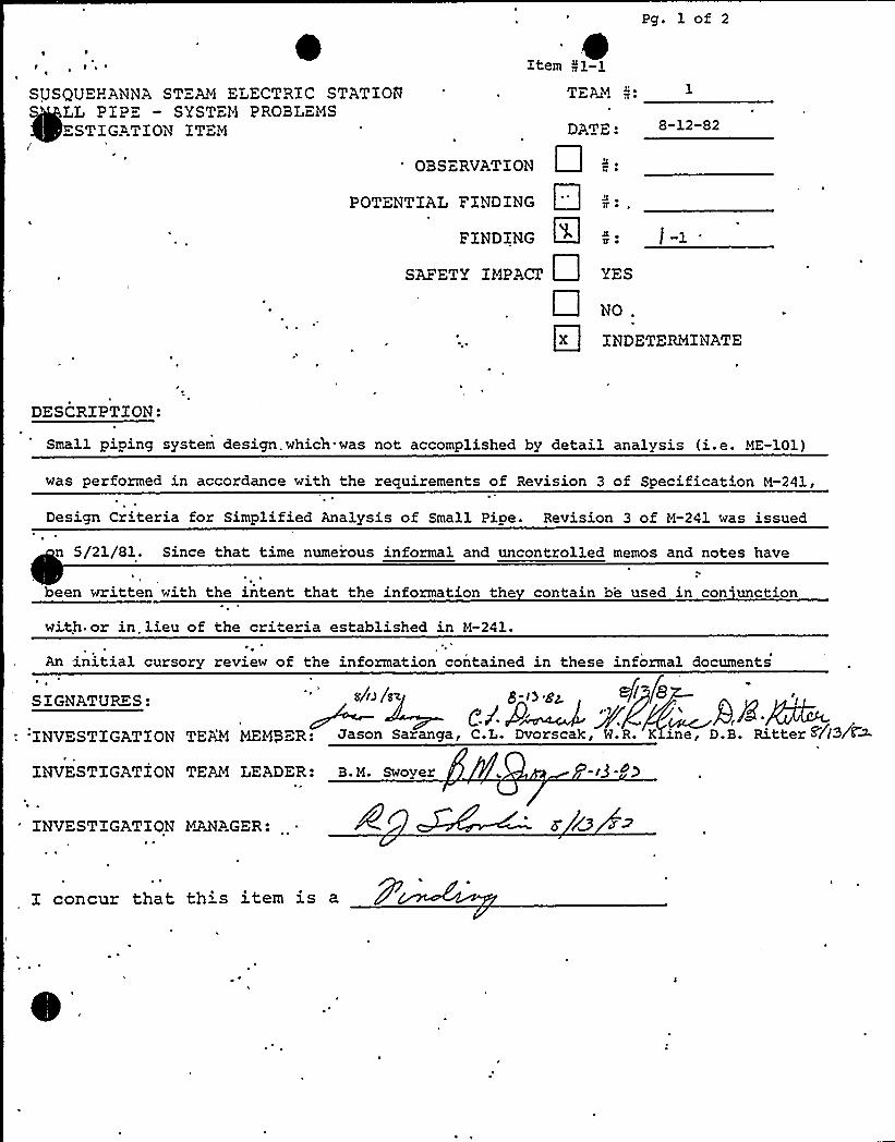
Item Prl-1: For the small piping system "as-built" designperformed by simplified analysis, Bechtel SpecificationN-241, Revision 3, was used. In addition, numerousinformal and uncontrolled memos and notes have been wr'ttenwith the intent that the information they contain be usedin conjunction with or in lieu of the criteria establishedin i&241. From the investigation sample, no impact couldbe determined on the "as-built" calculations reviewed.
2. Item f/1-2: Various discrepancies were, found on the Fab IsoESP-HBD-1538-1 and associated Hanger Detailtr'SP-HBD-1538-H-1. See Attachment A for specif'c details ofthis finding. These discrepancies indicate that thedesign/document control system was not adequate to assureproper processing of the documents in question andavailability of these documents to the appropriatepersonnel. It also appears that the interface between theResident and Field Engineering groups are not clearlydefined and controlled. The impact of not using the latestrevision of the Hanger Detail during the "as-built"reconcil'ation could not be determined during the time ofthe Investigation.
3. Item f/1-3: Identification of major and minor changes andhow these changes are reconciled are based on ResidentEngineering's conception/judgment. The 'sample investigatedshowed that some calculations contained major changes thatwere reconciled using engineering judgment, while otherscontained specific calculations (including computer calcu-lations) for both major and minor changes.
4. Item fil-4: The Stress Engineer's (Resident EngineeringGroup) Thermal Interference Walkdown requirements do notconte'n the controls to assure that the latest revision of

~ I
~~
the "as-built" iso is being utilized. See Attachment A forspecifics. Further investigation revealed that there wasno impact for the discrepancy identified.
5. Item Pr1-5: Combining several Findings and Observationsidentified during the Investigation lead to this Finding.Some areas in the small pipe Program itself and in theProgram's implementation are deficient. As a result,Bechtel cannot assure design and installations in everyinstance were carried out in accordance with Programcommitments. Reference Attachment A - Items /!1-5 for moredetail. (Note that Investigation Items (f1-6 through 1-14pertain to this Finding.)
6. Item Pl-15: During the Investigation Team's walkdown ofthe Diesel Generator Over-Flow Line, three (3) areas wereidentified as resulting from work performed after finalBechtel inspection and the system was transferred to PPSLjurisdiction. These items were determined to have noimpact, but this observation was noted to make allorganizations (PP&L and Bechtel) aware of the requirementto maintain the design intent of the systems.
7. Item //2-1: Small Pipe Hanger Standard Support and Detail(SP and SPA) drawings issued from San Francisco were notprocessed and distributed in accordance with Field Pro-cedures. Two hundred seventy-four (274) drawings werereceived in the field and not processed for distributionbecause the Lead Field Small Pipe Hanger Engineer (FieldEngineering Group) determined that these were not usefulfor installation or hanger design by Field personnel. Thehanger installations were completed and were designed usingunique hanger detail drawings. It was not recognized thatsome information contained on these SP and SPA drawingsimpacted Resident Engineering's final "as-built"reconciliation. This inforrmtion was the support loadallowables which had been revised to include the increasedPhase III loads.
This finding was verified to have had no adverse impact onthe design of the selected sample because it was verifiedthat any SP and SPA drawings referenced in the reconcilia-tion or original calculations did contain Phase III loadinformation.
The safety impact was classified as indeterminate becauseof the potential that incorrect (pre-Phase III) loadallowables might have been used for other small pipe
-10-

~~
\
systems. (Note Phase III reconciliation was performed inlate 1981.)
8. Item 82-2: Bechtel Specification 8856-M-213, Appendix F,was issued by Project Engineering to provide Bechtel gCwith definition of the inspection attributes and acceptancecriteria required to be verified to assure that hangers areinstalled correctly. These are the critical attributesdefined by Project Engineering. A review of Appendix Frevealed that it contained no criteria for clamp ear gap"measurements for friction type anchor clamps to assurepositive contact of the pipe by the clamp. The Investi-gation Team noted that this deficiency resulted inPL-NCR-728 which identifies that there are anchor clampsinstalled without adequate pipe gripping. The team deter-mined this to be a Potential Finding with no safety impactbecause the clamps in question have been identified forcorrection and the only question remaining regards anyother critical attributes that may be omitted in Appen-dix F.
9. Item 82-4: Identified that the criteria for inspection ofattributes associated with vendor fabricated components wasnot contained in Bechtel Specification 8856-M-213. Spe-cific examples .were the criteria for inspection"Detail 600" anchor clamp gaps and the criteria for in-specting sway strut installation and jam nut tightening.
This was identified as a Finding with safety impact becauseof the generic implication of this finding on small pipeinstallations and the installation of other systems andcomponents. There was no safety impact identified on thesample included in the Investigation.
IV INVESTIGATION ITEMS IN COMPLIANCE
For the sample investigated, the following Xnvestigation aspects werefound to be in compliance. (Reference Attachment B for documentssampled.)
A. Bechtel Desi n Control
1. The design criteria listed in Bechtel Specification H-241,such as support load tables, maximum pipe spans, responsespectra curves, piping flexibility, proper "SIF" and otheroriginal design definitions and intents, were checked.Based on a limited sample reviewed, they were found to beproperly utilized so as to have a technically adequate"as-built" calculation.
11

2. "As-Built" calculations for the sample considered recon-ciled all the changes reflected in the final "as-built"drawings with the initial "as-built" calculations.
3. The vent and drain criteria, Bechtel Specification8856-N-242, was properly implemented.
4. Based on discussions with R.E. Group Supervisors, thepersonnel involved in the "as-built" program appears to bequalified in the appropriate engineering activities. Hoqualification records were reviewed.
5.
6.
The Stress Engineer's (R.E. Group) Stress walkdown used toensure that all supports are performing their intendedfunction was found to be implemented properly.
All "as-built" calculations checked contained the appro-priate level of signatures and checks.
7. Field Engineering's "as-built" walkdown was performed tothe criteria outlined procedurally.
8. The transposition of redline information into final"as-built" drawings were investigated and found to be incompliance with procedural requirements.
B. As-Built Walkdown Performed b Investi ation Teams
1. The Team verified Zield Zngineering's walkdown to have beenperformed effectively in that all "as-built" dimensionswere reverified to be consistent with the current revisionof as-built fabr'cation isometrics and hanger details.
2. The team generally (with the exception of InvestigationItem fi'1-13) verified the effectiveness of Quality ControlInspections as defined in applicable Quality ControlInstructions.
3. The Teams genera'ly verified the adequacy of the ResidentEngineering Stress and Thermal Walkdowns to establishcompliance with the requirements of Bechtel Specification8856-H-213.
C. Bechtel Oualit Control
The following aspects of Quality Control were investigated andfound to be in compliance with the controlling documents.
1. QC Instructions (QCIs)
12»
a ~ QCIs were found to exist to cover all aspects ofpiping system installation including anchor plateinstallation, grouting, piping subass'embly, pipinginstallation and rework', piping system completionverification, pipe support installation, pipe systemleak testing inspection and pipe support final review.
b. QCIs were found to contain adequate description of thevarious inspection tasks associated with the in-spection subject, reference to governing proceduresand specifications, identification of referencescontaining inspection criteria, identification of themethod to be u'sed in completing inspection tasks,identification of any supplementary records pertainingto each inspection task.
C ~ QCIs were verified to 'be controlled documents andshowed evidence of required approvals.
2. Inspection Records (IRs)
a ~ Inspection Records were found to exist for each QCIshowing that all aspects of the piping system selectedwere inspected. This included, as applicable,in-process and final inspections of all hangers andpiping installation.
b. IRs were found to establish that QC final inspectionswere done to the drawings identified as "as-built."
Ce ~ IRs established that inspections performed during thedesign and installation process were completed inaccordance with the applicable revision of designdocuments.
IRs show the acceptability of the inspection tasksverified.
e. IRs are approved for close-out.
IRs reference the item inspected.
go IRs reference the documents which provide the'ccep-tance criteria.
h. IRs reference the applicable QCIs.
IRs document and reference nonconformances identifiedduring inspect"ons.
— 13—

~I ~
Hold Points are established where required; e.g.,welding, completion of weld records, hydrotestingapplication of pressure.
3. Engineering/QC Interface
a. QC was found to be receiving all necessary drawingrevisions as evidenced by correct references torevisions on IRs.
b. QC was found to be receiving Project/Resident engi-neering dispositions for nonconformance when required.
c. QC,hold points were found to be completed in a timelymanner.
4. Drawing Control Logs, Inspection Record Logs, InstallationReview Form Logs and the Hanger Punchlist (MAPPER) werereviewed and found to be maintained according to proceduralrequirements.
V. CONCLUSIONS
Within the time constraints of the two-week review, the InvestigationTeams conducted numerous interviews, assessed the adequacy of Bechtelsmall pipe program and its implementation, and" completed a walkdownof two small piping systems. Based on their joint effort, theconclusions regarding the small pipe Program and the potentialgeneric implication for other design/installation/inspection programsfollows:
A. Small Pi e Pro ram
1. Due to the loosely implemented program controls for designcriteria, specifications, "as-built" drawings, and recon-ciliation calculations, the Investigating Teams concludethat additional investigation of other small pipe systemsis required.
2. The, problems encountered in managing and administering thesmall pipe design program indicate that program controlswere not sufficient for the size of effort and time framerequired for performance. The Investigating Teams 'concludethat the small pipe design program for Unit,P2 needs to beevaluated for implementation practicability and should beredefined on the basis of such an evaluation. The Investi-gating Teams also conclude that increased attention isrequired in defining the organizational interface respon-sibilities in design particularly between Project
r
14

~ ~ ~ ~
Engineering in San Francisco, Project Engineering in itsrole as Resident Engineering, and the Field Engineeringorganization within the construction group.
3. Olhile the scope of the Investigation Teams'ctivities didnot include an assessment of training, the InvestigatingTeams, based on the complexity of the small pipe programand the number of contract personnel, particularly inResident Engineering, conclude that a review of program-matic training is required.
4 ~ awhile the scope of the Investigating Teams'ctivities didnot include an assessment of the Quality Assurance coverageof this effort by Bechtel and PP8L, a concern existsregarding Quality Assurance coverage, particularly duringthe final hectic period. The Investigating Teams concludethat Quality Assurance coverage for the small pipe programneeds to be evaluated.
5 ~ As a result of the Investigation Teams'alkdowns; theyconcluded that the Bechtel walkdown program was adequate.Thermal interferences and dimensional problems were con-sistently picked up and resolved. The Teams'alkdown alsoshowed that Bechtel Field Engineering's "as-built" programis adequate from a field dimension/hardware standpoint.
6. As a result of the Investigation Teams'eview of Bechtel'sinspection efforts, they concluded that Bechtel's QualityControl program was adequate, effective,and fully. met allcommitments.
~ B. Generic Im lications
Based on the problems encountered in the small pipe programat the interface between Resident Engineering a'nd FieldEngineering, the Investigating Teams conclude that all suchsafety related design/installation areas need to beinvestigated as a separate effort. The Investigating Teamsalso conclude that similar programs with "split" designresponsibilities should be investigated.
2.. As, a result of the difficulties encountered in controlling,.;:,'-".';: "::: "dist'rib'uting and utilizing all types of documentation
relative to the small pipe program, the Investigating Teamsconclude that a review of the documentation control programis required.
3. The character of the discussions with Bechtel field per-sonnel point out that some Bechtel and .PP&L managers
— 15—

~ ~lt
involved in the day-to-day activities were not sufficientlysensitive to the schedule pressures and their impact on ahighly complicated quality effort. The Investigating Teamsconclude that increased management attention to theseaspects of the Susquehanna project is required.
Vl. GENERAL INFORMATION
tA. Investi ation Makeu
1. Team Pl
B. M. SwoyerC. L. DvorscakW. R. KlineJ. SarangaD. B. Ritter
NQA (Team Leader)NPENPENQAProject Construction
2. Team if2
W. H. GulliverD. M. SattarF. X. McCreeshJ. D.-Murray
NQA (Team Leader)NPENPEProject Construction
3. Investigation Manager
R. J. Shovlin Asst. Project Director
B. Persons Contacted
Rajan ParekhBasudeb MukherjeeA. T. MorrowMohammed KazounWayne HuynhRuthann ZeitlerJules ColkerKen BuchananTim MinorDan GoodDan MontreuilDan HollingsheadDave YensonTerry McHenryGreg GelinasJames A. DahnertJitendra Khandha"George Bell
Plant Design Gp. Sup. (SFHO)Resident Engineering Gp. Sup.Resident Engineering, Hanger Gp. Ldr.Resident Engineering — Stress Gp. Ldr.Stress Engineer (RE)Plant Admin. (RE)Piping Field EngineeringField Engineering (Hangers)Field EngineeringField EngineeringDocument ControlAdmin. (Piping Hangers)Field Engineering (Piping)Bechtel OC
Bechtel QCBechtel QCBechtel QAProject QA Engineer
— 16—

Gene GlorvigenRobert SlaughterDave CronomizCharles KircherBruce HellsMike ScarcellaSal Di PippaBruce BaileyGeorge Drummer
Bechtel QALead QCE — HangersField Engineer Unit I Completion TeamQCE - PipingAsst. Lead QCE - Piping and MechanicalSmall Pipe EngineerSmall Pipe EngineerSmall Pipe Hanger EngineerSmall Pipe Hanger Engineer

~~
0
ATTACEIENT A
INVESTIGATION ITEMS: Nos. 1-1 through 1-15and 2-1 through 2-4
Pg. 1 of 2
SUSQUEHANNA STEAM ELECTRIC STATIONLL P1PE — SYSTEM PROBLEMSESTIGATION ITEM
JI
Xtem gl-1TEED
DATE: 8-12-82
OBSERVATION
POTENTiAL FINDING
FINDING
S'AFETY IMPACT
1, ~
4 ~TT ~
YES
NO
INDETERMINATE
DESCR1PTION:
Small piping system design. which.was not accomplished by detail analysis (i.e. ME-101)
was performed in accordance with the requirements of Revision 3 of Specification M-241,
Design Criteria for Simplified Analysis of Small Pipe. Revision 3 of M-241 was issued
n 5/21/81. Since that time numerous informal and uncontrolled memos and notes have
been written with the intent that the information the contain be used in con'unction
with or in lieu of the criteria established in M-241.
An .initial cursory review of the information contained in these informal documents
cd/~~. i 8A~INVESTIGATION TEAM MEMBER: Jason Saranga, C.L. Dvorscak, W.R. K ine, D.B. Ritter+(I3ff~
INVESTIGATION TEAM LEADER: B.M. Swoyer 13 d)
INVESTIGATION V~AGER: s lD
I concur that this item is a

I ~
Pg. 2 of 2
Item 01-1
indicates that Spec. M-241, Rev. 3 did not provide the Resident Fngineering Groupwith pertinent technical direction in certain areas of small pipe design.
Note: Revision 4 of Spec. M-241 was .also reviewed. As of 8/11/82 the spec wasin a final state, but lacked final sign-off (per Bechtel).

Pg. 1 of 2
~ ~ \ Item N1-2
SUSQUEHANNA STEAM ELECTRIC STATlONSi~L P ZPE - SYSTEYi PROBLEMSZB~STZGATION ITEM DATE: 8/13/82
OBSERVATION
POTENTIAL FINDINGs
FINDING
SAFETv IMPACT
1?p ~
NO .
INDETERMINATE
DESCRIPTION:
As a result of the walkdown of tne piping shown on SP-HBD-1538-1 (Rev. 8, 5/7/82) and
review'of the associated documents the following discrepancies were noted:
A.. Fab ISO SP-HBD-1538-1
(1) "Final As-built Drawing" stamp, required by PP-P-ll, Paragraph 8.0, was signed-
off on 6/7/82 approving rev. 7. ( One month after'issuance'f rev. 8, which does
not contain the ."as-built revision/reconcilliation" stamp)
(2) Hanger 51 had been removed on revision 9 (dated 8/3/82) on final
SIGNATURES:
INVESTIGATION TEAM MEMBER:
INVESTIGATION TEAM LEADER: n-/ - 2
INVESTIGATION MANAGER:a
I concur that this item is a

'

go oz
Item 51:1-2~ ~ ~
~ eI
(3) Subsequent to the walkdown the team 'was advised that rev. 9 (8/3/82) had beenissued to show deletion of Hl. Rev. 9 contained a 2nd "Final As-builtDrawing" sticker approving rev. 9 which was signed off on 8/4/82. Thisviolated paragraph 8.5.2 of FP-P-ll which requires a revision stamp and not ~
an as-built stamp.
Comment: Rev. 8 was given to the team by the RE group who apparently thoughtit was the latest revision even though they had signed-off rev. 9..The FE group, who had revised the drawing, produced a copy. of rev.9 only afte questioning.
B, Hange Detail, SP-HBD-1538-H1
(1) Rev, lF3 given to team for walkdown.
(2) "Final As-built Drawing" sticker for rev. 1P3 did not have RE approval sign-off.
(3) RE Calcs (final as-built reconcilliation) were done to rev. 1F3.
(4) Rev. 1F2 was issued'or cancellation.
Note: The document control system has no mechanism for assuring acancelled drawing does not re-appear.
(5) During the program for removing the "Q" from the first support after the endof a Seismic I line, this hanger detail was up-rev'd to 1P3 and identifiedas "insp. As-Built".
(6) After considerable investigation the original drawing, which had been up-rev'd to lF4 to "Reissue For Cancellation", was located on the desk of afield engineer'ho had neglected for several weeks to put it back into thesystem.
(7) Rev. 1F4 had both a "Final As-built Drawing" and a revision reconciliationstamp. Both stamps had RE sign-off.
(8) The revision reconciliation stamp indicated that there was no affect oncalcs.
(9) RE failed to enter the signed-off as-built in the log required by EPM rev.10 Section XII Paragraph 5.
(10) On 4/22/82 and on 5/21/82 the RE stress group walkdown revealed that hangerHl did not exist'.
(11) As of Thursday 8/12/82, the RE group was revisin loads on hanger Hl and theengineer was not aware that the hanger had been deleted.
" .Conclusion: The discrepancies noted above indicate that the design/document controlsystem was not adequate to assu e the pr'oper processing of the documentsin question. It appears that the interface between the FE group and RE
group was not clearly defined and that communicat'ons within the RE groupwas not uniformly established.


SUSQU ".-:ANNA ST AM ELECTR'C STATXQNSMALL PXP- " SYST"M PROBLEMS
ESTIGA'XON ITEM
TEAM
DATE
OBSERVATXOiV
POTENTIAL FINDING N:
FlNDING ~ ': 1- 5SAFETY XMPACZ'ES
NO .
X INDETERMINATE de ~44$ 'lS.
DESCRIPTION:
The use of en ineerin .iud ement to reconcile as-built conditions
in the small piping program is not defined in either M-241 or 8-213.
Discussions with R. E. Group (Bechtel) indicated that distinction
between major and minor changes defined in P.-213 Sections 4.15 and
4.16 were applied to large piping ()2") only, Identification of
ma or and minor chan es on small i in is based solelv on Resident enaineer's
conception ud ement. On th calcut'hangeis reconcilled, by engineering judgement and that for major changes - refe ence
SIGNATURES: attached calculatio er to attac ed des r'') ~
C./'XNVESTXG TION TEAM HEMPER: r i3/g~
INVESTXGA'TXON TEAM LEADER: B.M. Swover
ZNVESTXGATION MANAGER:
X concur that this item is a

Item 41-3Page 2 of 3
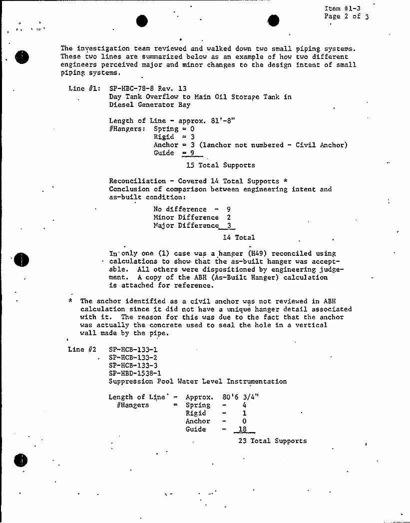
The investigation team reviewed and walked down two small oiping systems.These two lines are summarized below as an example of how two differentengineers perceived major and minor changes to the design intent of smallpiping systems.
Line 81: SP-HBC-78-8 Rev. 13Day Tank Overflow to Main Oil Storage Tank inDiesel Generator Bay
Length of Line — aporox. 81'-8"PHangers: Spring ~ 0
Rigid ~ 3Anchor ~ 3 (lanchor not numbered — Civil Anchor)Guide 9
15 Total Supports
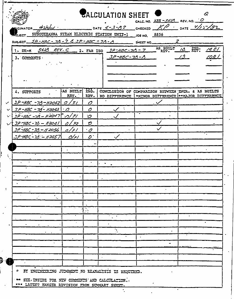
Reconciliation — Covered 14 Total Supports *Conclusion of comparison between engineering intent andas-built condition:
No difference — 9Minor Difference 2Major Difference 3
14 Total
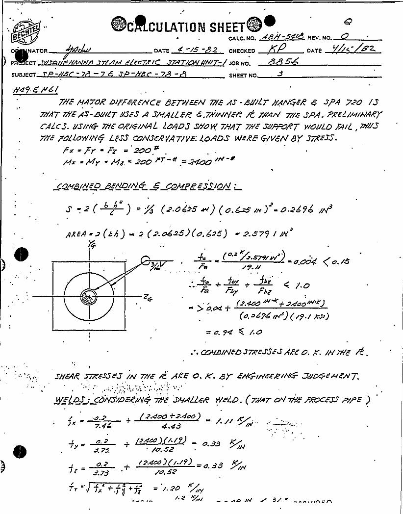
In'only one (1) case was a hanger (H49) reconciled usingcalculations to show that the as-built hanger was accept-able. All others were dispositioned by engineering judge-ment. A copy of the ABH (As-Built Hanger) calculationis attached for reference.
* The anchor identified as a civil anchor was not reviewed in ABHcalculation since it did not have a unique hanger detail associatedwith it. The reason for this was due to the fact that the anchorwas actually the concrete used to seal the hole in a verticalwall made by the pipe.
Line Pr2 SP-HCB-133-1SP-HCB-133-2SP-HCB-133-3SP-HBD-1538-1Suppression Pool Water Level Instrumentation
Length of Line" - Approx. 80'6 3/4"f/Hangers = Spring - 4
Rigid — 1Anchor - 0Guide — 18
23 Total Supports
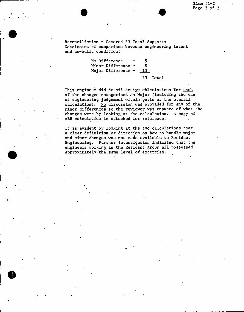
item 01-3Page 3 of 3
~ ~~
Reconciliation — Covered 23 Total SupportsConclusion of comparison between engineering intentand as-built condition:
No Difference — 5Minor Difference - 8Major Difference - 10
23 Total
This engineer did detail design calculations 'for eachof the changes categorized as Major (including the useof engineering judgement within parts of the overallcalculation). No discussion was provided for any of theminor differences so...the reviewer was unaware of what thecha'nges were by looking at the calculation. A copy ofABH calculation is attached for reference.
It is evident by looking at the two calculations thata clear definition or direction on how to handle majorand minor changes was not made available to ResidentEngineering. Further investigation indicated that theengineers working in the Resident group all possessedapproximately 'the same level of expertise.

I
0

I
RIG lNATDR/
+z+OJE|-, SQSQQiZA]~
SUSJECT Z/
OwLcULiTioN STREET 4DATE CHEC)CED DATE
ELE~C STATION ~ i 8
1 ~ SX-8 4/3 ~ CO~ITS
A'fV. C 2 ~ FAB ISO
SHEET ND
p- A/A - 8-7 A'//
SUPPORTS
>P P8C-78 -ff4O'P -//8C- >8 - HSOZi -HBC-7(9
"h'5/''P
H8C 78 "HSZ-ffBC-7' H53
S -//8C - 78 - ff54-ffBC«74 -h'5'5
S -ffaC-rdZ/ -H8C "78 -845
AS BUILTRVa
/'/sz
/'lrsA
&CoRZV o
I 2
CONL USTOH OF COHPARZSQH B~i~ ACR+ fc AS BUXL S
e+HQOR DX'0DE~ACE ~~nOR DZ~ VC=
ZP -HBC-Z -HS I Z/r~h.-HBC- 7a -Hd/
Z - -78-ff<ZSIC - 7 -H43
rP -//8C -78 -ZS4gp -ABC - 7<9 -ff45S -SIC -7d-P44Jj'fBC —78 -HgZP- BC'- 7 -H49
-ffdC - Zd.-ff7O-tlBC -78-ff7/
SP -ABC —7-HZ'ff8(-78 -h&94
3'P -fag - 78-ff>N-HaC -7d -ff~4
SP -//BC —7d -ff>o<O
ieger/ F2
zlzz/
oPsz0/rz
~d// /4* 7 . 1~~~+
C-ewe LA~a ~g~
l'O.Z:-~VW Sa ZS ~~V~. m ~ /> /</J p ~ 4/'/ '/-
CR ~iS hZD CLL ~~~OH. ~
R~SEON . ROH SUMMARY S~ e
I6 INATDR
OJEC i
OALf ULAT10N SHEETCA|.C. NO.
Q~~HA F~~~ KZCTRXC SZAX'EON UNIT-1
-7 3'HEET Na
8856
REV. Na.
2
3. 'O~TS-z~v. c 2. re ZSO
AS BUZL gg Pg. ~g+/
4. SUF. ORTS AS BUXLTRVe
ENCEREV+
COHCLQSXOH OZ'CHP~~OH B~DP~ '~i ~ AS BUTYL S
HO DE~~~ ~NZHOR DI~K9C= ~~Y3LDOR D
DP-PM -z -z~Mz olsi OS -hM-w -a~49
) n/ar3P -HSC - 78 —ffzoct/
-ffc9C -7 — ~Q y/ /-M(-y -'~cS'l~i
P . iW~~VG Z~MH~. BO RMaLYSD ~Q ~GZ~M.S-. s i~Z:OR H-~ CO~ S RR ~L'a OE ~
LA~ HQ u~ RZVTSXOH .ROM SVM~T S~.
I
'<'+DONATORPR ECT
SUSJECT
o \
ec%cu~Tiam sH<~TO. oDATE
J'~ r /tN~ -/JCBNo.
SHEET NO
7'A7OR >~FFFRFiYC'z 5ETlVEEA'iYE AJ'-8//87 ffA/VCj~R 4 >r A 740 IS7HA7 rVZE'AS-Buldl ASFZ A ZWAgZZg 4.7p'Wh'FR / ZpWA'Z SPA- PRES/mwAg7rAZ.S. usa+ rivzoEr'WuYAL doADS stol w87 mz su~ET'cuZO Fiid w>Ssf'olloeiNQ lZZS conlZ~RVA7/yz.'odDs WsRE &Yah') ZrR~~S-
g» «Py lP = 2aC7
~x ~Ay «hQ ~z~+~
cawgxHEo 8ztYo/A'Q 8 cc~+zs+tohf:
Z 2 ( g ) = Pq'z Otic ~.) (O.~ io) -O Zoll ZQs
h'ARLA
o (kh) > (~ o6»)(e.425) RS7$ IA'q
~
~-("r'', <(...sr9. rr
Fa Fop
~~ ~4 <zw-kgp o~+
(e.>694uv ) (rg.r pzi)
= o. 94 w+ /.O
. - mesa'F8 z7zazSEs AI'zo. g. w'P/z 8,~
'h'Std STgzsSES /A 7M 4 /ZE O. k. gP Z~irveERWCr Qz~FaEA'7.
HlslaS~ cu SzssR>rt+ %z zeadlzR eoZD (rswr cW eP )ÃMFzS azpz )2.405 +'2 4dd r )r i//
rW4
~
h
o. o >.ooo < tP o ~g~p'.79'o.<2
ro oooo i.r9).o.73 ''o. SZ
4 g s WrsA') ) +f — r go reJAI
Kg r 3r . ~ (nrn

~y$
DONATOR
PROJECT
SUBJECT
ecaLcuuz~oN svEET ='SdDATE CHECKED
C C - / JOB NO.
'SHEET NO
Hw gzmguv'uv4 PYr/zS~ zu~~7-ZZz a. <
DATE
., AS-c5C/ll7~~E'RD H<$ 4 H4/ AA'8 O. K'..WR i7/F Lt7FZ7WADS'IVY&
ASOYF.
h'58 /S 3 AATOR DiFFFREAIC~. BECAuSS AS tailer HAh'+~R Has DF& r AS'rAECeD
yh'li.E ZudznlEE'Rzh'$ DrDIVT CALi ~R ll . Adsc7 WE NeZDS oiv 7/tz EBS or/pe~ 2 ARE /z Ac-A/.'orat'h4) 5'Htlz ENCrezeRIN+ oA'd7 GdlcvlA7FD FoR 4Fl/ZZT ON TWO S/DFZ. AlSO.ADO'7/WZ ~ g 4'AZOR CpaoHF 7RQbt~/EZEN<F. HoPEYPR SdPFMT IO'o. k. clap &/4/AEpR/A'+ ~@NFL'EW7,
e+ ts A HA7OR DIFFFA'FA'CF 8876'FZh'i'F AS-WIL7 ffA~E 4 7ffF cVALJ87FD OrVF,
/A NAT 7/rF'&77'eZ p cmsro~R'zO aoAos ave 7O 4 arracS/wzk7S, Wrote
,4Z -u'tLT 4 ~vAlttd7FO cavo/7./AS.Ac7'uALAS -atr/8.7 /rAN4.zR /AS zg~acagzw7Z ~ 2/s7za azdoegR'E m'Z
Ht/
HZd~9
ff>os%
Hzo57
ZoACZ dJBDIe
FYA/vATrcA'x
Fz =47
Fx =5g ~gpy>
Fx ~ 4/4Fz =~o
awZZDÃrb
pz = ~sO"
A5'-~IZ7 ~DSj»Fe ~47
zsr"gx ~
Jr'z
= Wo~
Fx Fy =? P4
—gyp 8
W~H~R $7FESSFS;
grrtCE IN~57 ~FJ'~pZ, 7HF &7<87 ECHOES AAF &e~R AHA~ OE aud4L
7VOJF I/SZb W rgZ pyAt.uA 7/a&, Ah'0 7rYZ mEA'8FR ZrsFSJZZ FROrV VYF J 14>DL
~PE7ARF ~ow', /r/F gaorrrorbg/ FFFF<7$ MF'D wF ph'ccvYs/~zEc-bhah'4'vl.l
h'o jovzg zTRFZZ 7v wF zxis7/iver@'YF'M8FR2 8Ep'owo ~z Azro/ABLE~,

'gt:~
INATOR
PROJECT
SUBJECT
~+Lac Z'rc7~+;
eclccuuaioN sH<vCANC. NO.
CHECYEO
/C hl / - JOB NO.
SHEET NO
OATE
jp'E'Fjdzc7roh's IppAgl pj'PRE oiz~c7ravs ARz cohzlDegaBD. ~a~«i@A~/7fftgd&WABL5 Pch W4 7ftF vAMA7FD +Ah'Q HA~R - 8) zMfPEH~~jg~z+EA7 7FF ADDED zppEC7 Cg/Z /23 ~p gpp/7r~gg 44hl&g'//L ><7 Mz~s< ezAC o~Pzzc7rohS m acmic wiv ALZowA<cF.
- ~ DzPdzc7roAS ZZE'. K'.
pgzauzwcg >
FZaauzNC ) /S o. g. g) reSp/. c'Trod op ~NZT~~Q $%4/DZ &7Pd7 4z+6in ~~RuV$ Ju~wzA7.
~gzg g &fsE 4
Z -auI87 ~~+
MJZHDS'

DATE <- »
~ ', ~ICALClllATiCNEHEETG
INATOR CHECKED
) ~ /PROJECT / I JOB NO.
SUBJECT t - C- SHEET NO
rz A wave DID/'FRF~(E. 8'Ec44'Jz As Mil7~nv~4 'g/y HAS A A'E+b'ZAP
.,:,.;~Cp~ Cud. HO6eYFR'ff/LP FA4uv'FE4W'+ CALLZ4)
gS ~/g7 ~D/r/oa/3 O. k'. r Z SPA Z7/.
, ~ P~ PrggF 7'aive ~/~~ AA/IVOR'D/FrÃRFiV(Z. cFFC'ASST AS-BCl/Lj WELD iZ O//'
, g /g O: rt; By'~+ih'WR~~cAleulgiED Fog'< jidlz;7. Po+zy'M 77//J')iP/&PE/~
gila~ZH7.
/td4 /SA ~/hgR o/t7FRFA'CF .8FC4!leaf AS-ou/c7 WE'D /S/8/~~~lcu&rfD~E /''/if'. uoezvfR mis or~rRFI/ /
XIV+:r/E&PrtVg 3/~E~&V7;
i;@" ~HIER vSM uY87/S A gi+OE C /SF~RE'~(E . 'BZCAl/SZ AS -~F7 T/rl/ZLD rZ E~ ~~Maw7;CALCULATED~R. AOWPV~R'HrZ DlmaPZAC(Z /J O. K: ~j
~ RF:re~+CEWZ~j~/r' ISA hllkoR D/~iFRFA'CE. VFGfuSEEiV4/WFFR/w(g CAEZ f/
,). lD 4 . rVORPVFP|.'Z. Of/LF As - aurd7 r54v+ER Pds rrlvEF/ r/'
8u]CQ cONO/Tldpl rS O. K. ~4 SPA 44/.
~rP A /< "r'/QZ7u~S~ IS A OIAoR o/FFFRF~CF. 8zcduSF z>6ravFFRIN+ c'Al///
i<~ . hoesVFQ %/SWFLD oh'F ~~FD g. g"/ZF At -udt WED /S'0+81
O/PPFR~h'CZ /Z O. K. 8f'+rPHR)N$ Su+caZA'/
y ) ME H&099,HZO34 /Z A heaOR D>PFFRE'h!CZ gc(Al/SF'F ~Z SMF ~8><r'/
„- mfa -Hilr +NOIR Dbrc7~aAC IS A ~A~OR O/IFERfefo. 8ECAVSF fYALVATFDff888C>
<y FWGWZZgrkg ~Z~HZeirA'cO/HF'747. ffoS'EVE/ /4S'7AEZ FQ ffAnlgFR rO'.


~~
CALI:ULATIGI'"SHEETe gP"'ALC.N
~ ~
OAIG)NATOA DATE ~ + CXECKED
PANDECT SUSQv Rat EA Sl 4 IRCKC S»~ OH uaa' IQQ L)Q
SVmECT
P'~~ )
8856
C.TE
3 ~ 'Q~~S .
5 = 6'R~6JUANA)'7 KQC -I
F'-Hc6->~- W
' ~
4 ~ SQPPOBZS AS SUZ
RVo- )CoR Vs
CONC USEOH OP'A~~SON B-„8~ =t~e E AS BUT S
HO DL~MIC. I ~H ~ NOR DT~DfC. I~«3JCR DI~ HC-
SP-4 >Z -H.t 1/WP H 8-i --DM o/~~ I
t Hc -> -Ha oft'> l
ROC S-le~ V4, t O/P uC -i -4 I ~/Fl
SAVE,a- l="-0 lC I =-/P]F"-Hgg l- All t, lz
F'~C.S W~ uiZj ~/aa -O~lj OIJ-I
9'-llr$ -l~-&mal 0/CI<Cl-o'IE --Aw 0r <l
Cr
Ci,
Cj (.
Cj
Ci
Fa -i-~-v~ ~2~ 0/t=f l oIc
I WM lmS-Pr~ j 0/~ZIe
F. Oc,<-l~ - uZmoQ /<Z.w -r -Aza Vi o/F'IJPCR- l -Lj) l 0/~
r VC -l~e-0»ll CJP'ZF'-H. s- -o~~nl O/Fz.
L4 B. )- llama>50/P'l"--HZD>AO/Pao/7
j*
j
j i+
* E. ~~",„~~~ ZO ~~
w p ~ pa ~ i ~ e'~I"8 'Iw ~ a ~W ~e+,e w "~ ~ ~
see g~~ BBK R=-PSZOH BCH SPMPZ S~
~ ~

- RZ Od-
CALDULPTtQf'ir~<"-"'i'
ORIGINATOR~tAl < ZC-r3 DATEI
PROJECT
SUBJECT P
SH ~"-TCALC. N
CHECKED
JOB NO.
SHEET NO
REV. NO.
DATE
yg '+X+IYz
12
13
14
KFF. Lcp~<
WG'5)@Al LcA>5 m&a . Rl
1
1P
19
20~ SX ~7.+x/C Xllifgl
o, oug)or DO
22
27
30
31
32'
33 ~.35
pQ = 54-A = o,bcGG)bAB .4 /+X~I @X/D (o Oof
C.HGcK [email protected] +Ppx Y~//~
Mx = ZSo X+% + 5'// xz75
hllbx Novi@fL WTPE5.5. = )>A'~ e 5!)5 7o ~/+
= zd-4o,=~: /1)iu Pszo.4
SPP 20168 Aev. I6/76I, 60 69 IQ/y6

I ~
ORIG INATOR
PROJECT
SUB'JECT
C JINNI:U |STR 0 N
I,N DATE
St-! EETCALC. N
CHECKED
JO8 NO.
SHEET NO
8l~e
9
IO
12
~ 3
14
15
16
17
'!3
O20
21
22
Ap't RDs puL.t oUT
p,yo / ~47wx8
~SAN = Fii+
t Micah)G &%
gg PM X'A'<)1.x w>'I~
I+
23
24
25
26
27
28
30
32.
33
SFP 20766 Rev. I6/76) ED@9 16/76)

4~ P A t P I ) f p "fl 6" p I Q f ' ~,HT6 C~ L M c3 mH c h ~ s'~ 8 i i i ~
gE CALC. N~p
ORIGINATOR ~ OATE ~ CHECKEO
PROJECT JOB NO.
Sue JECT P- SHEET NO.
@8,SF 'HC8 -I» -HZcc I 4 Qzoc~H$g OP-'HcB-.)~h ~G 9omo<v- FQRp~
4 ~~5 PZmI
OATE
II
/g~l 5 //
9
10iQ
ll12
13
14!
$ ~05 s
Ak~r~
je18 ".
19 ~20
21
22
23
P ~~Jp'x
GI=F. 39'
5G&if'~a,25
27
Fl7
5&&/4// "I 4 ..
.30
31
32
'ht-~o5RES)QN
lx'7N
35
SF P.207SS Rev.(6/761'D.69 tS/7!

g ~
gfjl""P
OR IG I NATO R
PROJECT
SVSJECT
DATE CHECKEO
JOB NO,
SHEET NO
'~I.ALCUL-"<T!Qi'! Sll."E ICALC. N REV. NO.
OaTE
@gag gzycy c g
10
11
12
13
F.Py GZ
l7 X3.~~5 ~ ) 7x)z 43.9)cz7+xt Ro.>l 3x>7$N xl 7L
0 ooo27 (o,oogI xaam
A — I xZf.=Z:6< = ~ S'xi J, = o ~'~+
18
19
20 O21
22
23
24
26
27
30
31
Z->JR.
H moo
Pl -> ~ PLr.AK 'B'>m
' 7z- xQ Yg ~ 7z x/2 4E~pg z7 fgg) Q/ z7+4/+wl'7D
o- co(g (oi ooP
PI<-6 = ~'—Ehx'F.b> ~ %Ax~~g,~y~z7,+gg - ~xz/.+,Wfa x 1/.
o oo3-L" (ooog'2
I QHt II. gag, Q+ +X4-W j~
35
Mx- SF>-207/8 Rev..(6/76)'~
— w7>~pp + y~ex+ 5.+.i Tk.xt'43
= X H x') z ' = ~~'77ED 69 I6fr6
I ~
s<'0
11
12
13
14
)qadi~ 8
P
ORIGINATOR
PROJECT
SUBJECT
CALa U&7iQ[J:llEEfCALC. N
OATE ' 8 + CHECKED
j JOB NO,
zco5 SHEET NO.
rAl;
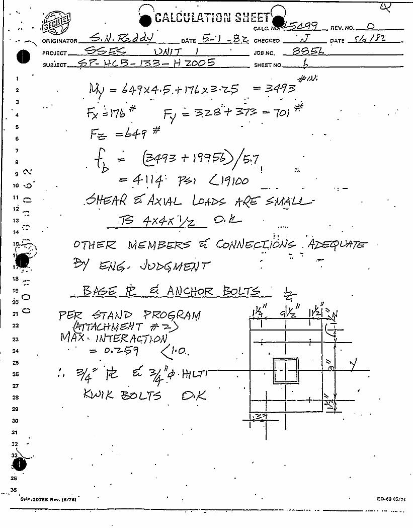
Mq = Ap >'+ f+nL>~ ~g = 3+vs
Fg =)7L p = BzG+ E73 = 7g)
Fw =407 +
/+V~ ~ )9~54)I
7+I C I9(oo
~P <AXI/)< L/~I ~ +~ SaZ~-)S AX4-X'.
REY. NO. 0DATE + ~ EZ
18
19C)
20'1 ~22
23
24
25
26
27
OTH c ~ M& Iv)PER~ 0 Co//AIO'CI /D/JQ
W ~84 J.~vgugsgr
5~+8 @ 6 Agc~F.
psk WIAQE Pvoq~g/AT/IQtV(~//-T m )
g/IX IQT.gggc)ID/.= o,~Fg (fo
~ >/ P HICVi
IK ~g~g ~,y30
31
"2
35
36
SFP.20766 Rw. 16/76I <0 69 t~/7<


. E~~~))I E
g)C
ORIGINATOR
PROJECT
SUBJECT P U
I'ALL'LIL'~VI0 M
DQTE +
Ytl�at)
E )EE (a/ ~ltsf~~ b
CAI.C. N
CHECKED
JOB NO,
SHEET NO
REV. NO.
slv Er.
8
9
11
12'
13
'l4
,~~RzooqF~
F~ Hzeoe
C)'021
22
Ltg Ses7
, 23
24
25
PSGIQA)
30
31
32
33 ~
0 ~oo
F rZ.IY)
'DG51Q)J
SFP 20788 Rev, (8/78I 8O.ee land

0

.~pl Cp,( ~;lw~
OR(GINATOR DATE0
~ PROJECT
SUBJECT ~~ IW '9 Ztoo
CHECKED
JOS NO,
SHEET NO. 8
9
10 ~Q
FR~gOSA''~ ~A'~~ god% CAO7 P V7. 7
I Jp, 7) —ooo,g3. +A/ o,oog
Q4 l, 7) o.oto72 (o.tooq
12
13
14
R a Far guaÃcy'.
~19
- G20
21
24
26
27
28
MIGLl>5, &AS.C 8, +@~Ho& Kw7K
B/ - 4$ ~ ~Z>glrl~A/7
go(o $ Zo(S-
30
31
32
Ig rrg'7iM6 $/RrMcp ~j g g rg F~6 G-Z g 8 gf p f coOt
PZ . (o~rtas cRRsti) fptzctt tn'csttrc7cd
J'5
SFP.20768 Aev.16/76). 6 049 (Sn<

OATE
Mj)jf "t ~I:~ LCUt RT!Ut'3 Sl-! EE)ggG CAI.C, r
ORIGINATOR -Bz „„„,~PROJECT JOB NO.
SUBJECT - Qt-8- )3E- SHEET NO
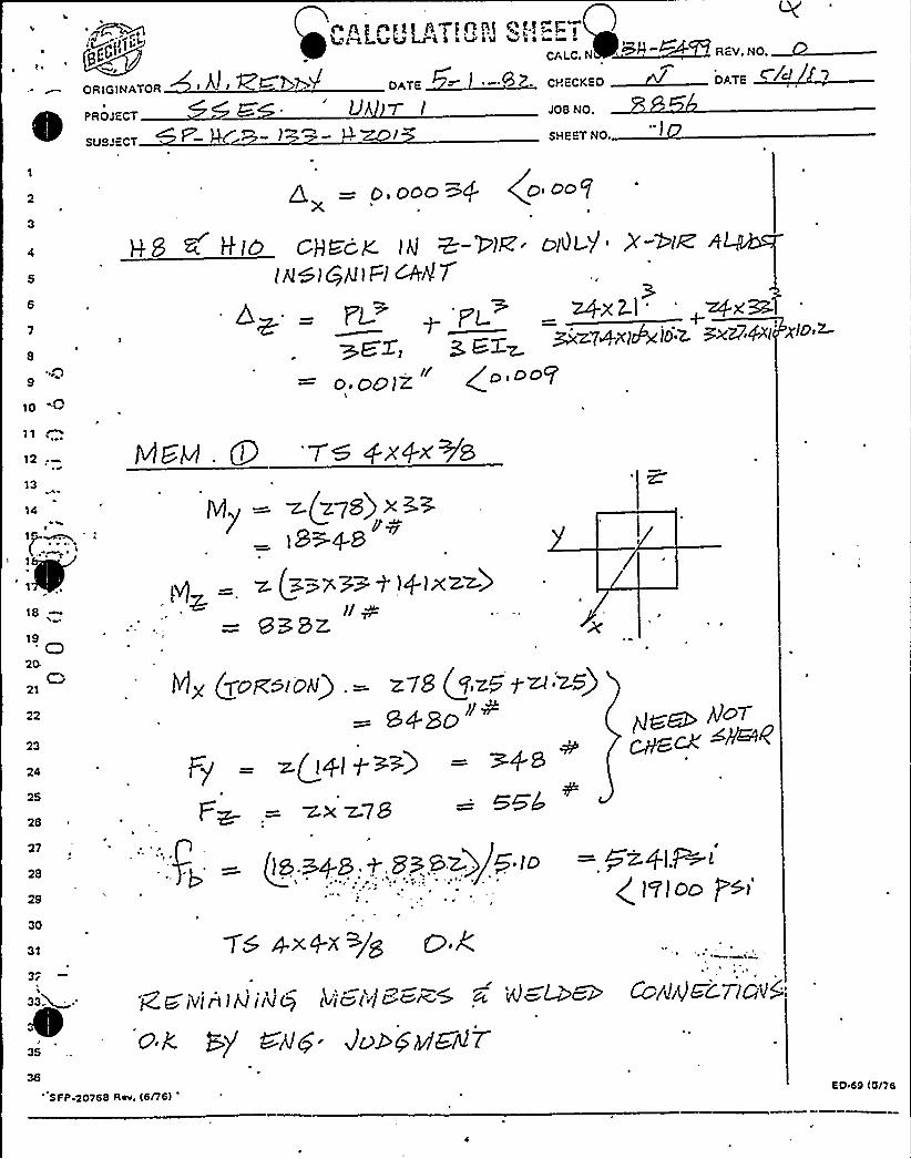
HQI7+ gP -'WS-)9>-8&, lflO Egest>g5oF7c R7ZV t=go@ HgZ'~y~ o- SF'-H~~-l~>-P,m
H~ly . HB
Hzol4 ' ~ic ( yyx+~ 8
rrIf //W
10
11
12
13
14
I
Fx
T'I~I+
L.zxsx ~/g
18
19
20
21
22
23
24
25
26
21
2B
l'y +x4.</0
H zen 5 Ifmi4--
.HS EHlo
zesiqA. ~4
~F
GLGu, Lf g., <DL'f78
30
31
32
35
r ZK6? UGAlC.V
H z.ol> 6 I-Imlf
SPI'.20768 Rev. IS/76)
PL ~ P'l+X P~ y~z.
M~ j9E7»I%27.Ix) Bxw7.$p lop E,z. SD 89 (6/76
I~ ' r
ewe ro
F r r
J pJ
rP r r~
f
~r r
J
./
r r

g)l ""
ORIGINATOR
PROJECT
SUBJECT
('>x~ Q
6 LPi")J lj'PI+ fjI
~dA OATE
SHEE."
'I 5/JOB NO.
SHEET NO.
n
10
11
12
1~«
14I
IB
1
9 A&~ 4: Z AfjcpoR'oL.(N
I/PGKP%')@RAN.f (47 7RCH VENT
ww)((J(sRAcv(od
= ~.+~7 ((o
f 9(LTI
~N)< <D G g~
19
20
21
22
23
24
26
30
31
35
SFP.20768 Aev, Ie/76) 60 69 Iene

g'4444'4'4444444444444444444444444%404ei40e444
UHIVAC 1100 SERIES ICES s
APR 29, 1982 ! . 10i52:14VERSIOtt 2.9
'j
. ~ 04444. '44444444444444444444:i4:i4:iW4:if i4:i4:i4'i4
>OADD l:CB1331I2009.1. ''.i'(RUDL 'S.S.E.S.'885&'
~
3 ~
4.5.6.7 ~
8.9.
10.11 ~
12.13.
'14.~ 15.
1&.17.18.19
'0.
21.
:i0:i:i0:I i4:i:C 0:i 444:i 4:i 0:i 4:i444:i t:C 0:i 44 i:Ii:i4:I
ICES STRUDL-IITHE STRUCTURAL DESIGtt LAttGUAGE
CIVIL EHGIHEERIHG SYSTEtIS LABORA
MASSACHUSETTS IHSTITUTE OF TEClltlO
CAHBRIDOE i HASSACIIUSETTS
10.52.52 29 APR 82
UHIVAC 1100 SERIES EXEC 8
VERSIOH 2.8
444444444444444440 4444444444:if:i4:If 4f:)Cl
T ITLE 'SP-HCB-133-II2009 SE ISHHIC CLASS
0 IHPUT BY) SH. REDDY DATEi CHEC
(YPE SPACE FRANE
ltHITS IHCH KIP DEG
JOItlT COORDItlATES
00 0S2 0 0 3&.75 S
3 -3&.75 0 0 S
405505 0 55 -40& 7.5 55 -407 19.5 55 -40HEHBER ItlCIDEtlCES
1
224334145
".i 5 &
')&7i'']'-; 5 EHD JOI SIZE STA 2.0

26.27.20.29;30.31.32 ~
33.34.35.36.37.'8.39.40
')
~
42.43.44.
IAB 'lu)!t.b''lalA')5 6 TAD
'STUDES'T3X3X4'<)HSTAHT
L 27400.0 ALLli 10540.0 ALL'HSITY .000284 ALLi'))I 3 ALL
ETA 0.0 ALL ..LOADIHG 1
.)l)I 6 LOA FOR X -2?1 Z .220U)I 7'OA FOR X ~ 154 Z ~ 395
l OADIHG 2 FREO Z
JOI 7 LOA FOR Z .044DEADLOAD.Z FAC 0.5I.OADIttG 3 'FREQ
X'!
0 I 7 LOA FOR X . 028).:EADLOAD X FAC 0.5:-. (IFFHESS At)ALYSISI)UTPUT BY HEHBER
IIIIIPUT DEC 4
).)ST FQ!tCES REACTIOHS DISPLACEHEt)TS ALL
{) {! {.'! '0(! ' '!:! [) n ')
0 I 4:W:I 0:) 'i:j:)4:) 44:h4 f04:i4404444
'RESULTS OF LATEST AHALYSIS*4 l h ff44) 4) 4 I 4) 4 l444$ 44444044
) ROBLE)t - S.S.E.S. TITLE - 8856
ACTIVE Ut)ITS'HCH l(IPS DEGREE DEGF SECOHD
ACTIVE STRUCTURE TYPE St'ACE FRAHE
ACTIVE COORDIHATE AXES X Y Z
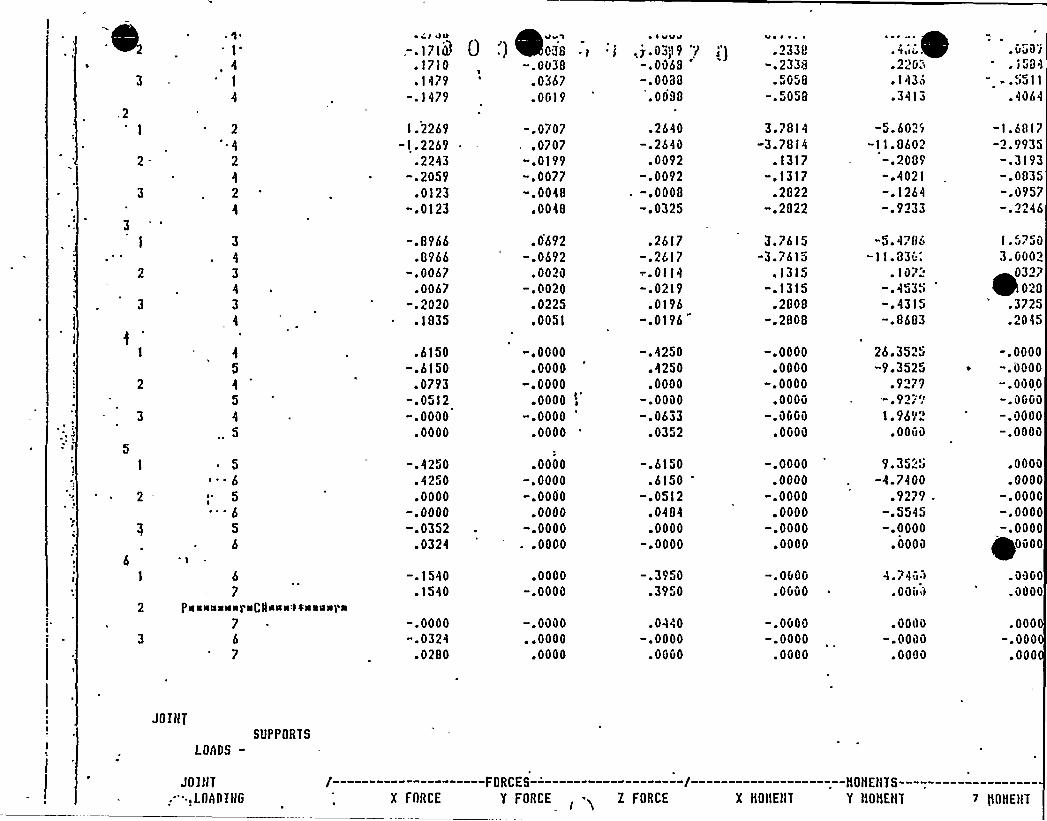
i)EHBER FORCES
t)EHi:RLG .)>IHG JOIH T AXIAL
FORCES
S))EAR Y SHEAR Z TORS IOHAL
-HOHEHTS-DEHDI)IG Y OEHDIHG Z

0
1'~ r'I JII
.,-. I? 10~
.1710
.11?9-.1479
,~v ~
0 .') m03S .)-.0038
.0367
.0019
~ I vugg
.j.03~)I9 7-.Oa'&8
'.0088
.0088
.2338-.2338
~ 5G5S
058
I~ 'I ~ Iu. 220..143&.3413
~ VJO I~ I J8'1
- .5511.4064
1.2269-1.2269
.2243-. 205'9
.0123".0123
-.0707.0707
".0199-.0077".0048
.0048
.2&40-.2640
,.0092
-.0092-.0008-.0325
3.7814-3.7814
.1317-.1317
.2822«.2822
-5.6029-11.8602
—.2089-.4021-.1264-.9233
-1.6817-2.'9935".3193-.0835-.0957
J'I46
3
3
4
3
-.89&6.896&
-.0067.0067
-.2020.1S35
.0692-.0692
.0020-.0020
.0225
.0051
.2617-.2617—.0114-.0219
.0196-.0196
3.?6 15-3.?&15
.1315-.1315
.2808-.2808
"5.4?86"11.330:
.10?'.4315
".8603
l ~ rIr JO
3.G002032?
028.3725.2045
.6150".6150
.0793".0512-.0000
.0000
".0000.0000
-F 0000.0000
-.0000'0000
-.4250.4250.0000
".0000-.0633
.0352
-.0000.0000
-.0000.0000
-.OGGO
.OGOO
26.3525"9.3525
.92?99');II
1.9692.0000
-.0000~ ".0000
-.OOOO-.OGGG-.0000-.0000
~ 5
6~ 5I
6
5
6
".4250.4250.0000
-.0000-.0352
.0324
.0000-.0000-.0000
.0000-.0000..0000
-.6150.6150
".0512.0484.0000
" 0000
-.0000.0000
-.0000.0000
".0000.0000
9.35"5-4.7400
.92?9-.5545-.0000
.0000
.0000
.0000-.0000".0000-.0000
0000
&
7pgssassspaCIIags44saQSIrS
76
7
-.1540.1540
-.0000-.0324
.0280
.0000-.0000
-.0000. F 0000
.0000
-.3950.3950
.0440-.0000
.OGGO
-.OGOG.OGGO
-.OGOO".0000
.OGOO
4r?40 )
~ 0 nilil
.0000-.0000
.0000
.OGGO
.0000
.000-.000
.000
JOIHT
LOADS-
JOIHT,', LOAD IHG
Supl'ORTS
X FORCE
FORCES
Y FORCE -5 Z FORCE X HOHEHT
-HOHEHTS-
Y HOHEtlT 7 QOHEHT
2-I2
3
I2
3
GI.O
~ GLO
~ ) J8'I-.003g-.0367
.2640
.0092-.0008
556-.0054-.13IO
0 0i~~ 1479
.9809
.17 5
.00?5
—.7071-.0044".15S4
~ I GOO
'i i ;j.0339 1-.0088
-.7404-.1412-.0108
.2617--0114
.0196
4 ~ I I I v".4&89".1436
- I . 681?'-.3193-.0957
6.6451".0161
.5147
V ~ IllI
.2338~
.505i
.0311-.0066
.164'0830
.1689'.0062
&0 ~ I ~ ~ I
.05G9
.5511
he?595- "168-.2619
1.5?50.0327.3725
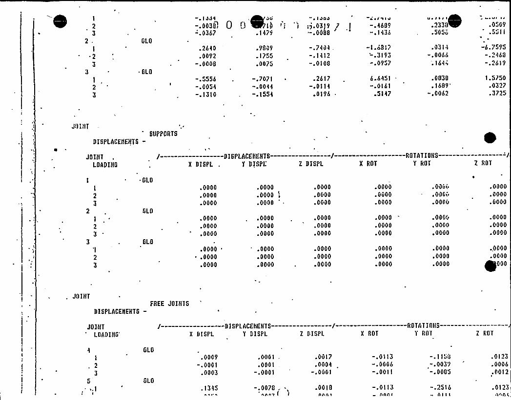
DISPLACEIIEHTS-
JOIHTLOADIHG
SUPPORTS
X DISPLDISPLACEHEHTS-
Y DISPL' DISPL X ROT
ROTAT IOHS-Y ROT Z ROT
I2
3
'I
2
3
GLO
GLO
GLO
.0000
.0000
.0000
.0000
.0000
.0000
.0000'0000
.0000
.0000
.0000
.0000
.0000
.0000
.0000
.0000
.0000
.0000
.0000
.OGOO
.OGOO
.0000
.0000
.0000
.0000
.0000
.0000
.0000
.Gvoo
.0000
.0000
.0000
.0000
.0000
.0000
.0000
~ OOvv
.GOGO
.oooo
.0000
.GOGO
.0000
.0000
.0000
.0000
.0000
.0000
.GOGO
.0000
.0000
.0000
.0000
.0000+000
JOIHT
DISPLACEliEHTS-FREE JOIHTS
JOIHTLOADIHG'DISPLACEHEHTSX DISF'L Y DISPL Z DISPL X ROT
ROTAT IOHS-T rar Z ROT
GLO
GLO
.0009".0001
.0003
.OOG1
.0001-.0001
-.0078 .hhh'7 1 )
.Ovl7
.0004-.OGG1
.0018Anne
-.0113-.OGG6-.Ooll
—.0113nnni
-.1158".0039".0005
-.2516nI 'I I
.0123
.0006
.0012
.0123nnn l.

(IU
I
2
3
I'X
.00
.00F 00.00
I I
.35".35
.35
.35
;56 ()-.56
.56
.56
I IA
-P.ll'.48
8.40
llI, IIL3" l f B.'30,)
"'10.35 -8.3810.35 -8.30
"18.38 8.30
ll I A&Ii)'I . PP g )
I.?b'.70
1.70
." T A H D —STREHGTH DESIGH OF A»CHORS -- VERSIO» 01
SW-It t:B"133 "H2013
.LL IHPuT AHD ouTPUT la IH KIP-rtlCH uHITS
PAGE'
DATE 050402
"HcuoR Ig GHEcI<ED FDR 4 LGPD co»DITIGHs As TABULATED BEL'ou
LOAD
COIID
1
2
3
FORCE
X
F 00
~ .00.00.00
FORCE
.35~ 35.35.35
FORCE
Z
.56-.56
.56
.56
HONEtlT
XX
8.48"8.48
a.4S0.48
IIOIIEHTvv
18.35-18.35
18.35"10.30
tlOHEHT
Zz8.308 ~ )a .
-8.3aa.3a
K-fACTOR
1.7001.7001.7001.?00
S T A H D"" STREHGTH DESIGH OF AHCHORS -- VERSION 01
SP-HCB"133-82013
PAGE 4
DATE 050482
ALL I»PUT htID OU'[PUT IS IH KIP-IHCH UHITS
ouipuT Fon LOAD cn»DITIDH
DOLT SIIEAR FORCES htID TEHSILE CAPACITIES
I:Ol.T J-"--SIIEhlt»0 v
I -.1072 ".107
.201t
FORCE- —.-jZ
-.055.333.333
J —TENSILE CAPACITV"-JDOLT PLATE
1.595 3.1431.561 3-143l.539 5.650

5'fl(ESS BLOCK ItlFORHATIOH .
/--~————tlOtlEHT YY--"—""—--/ /-—--—""-"tfMEttT lZ"—"—--"-"/ftIDTH(B) LEHGTH(L) DEPTH(A) llIDTII(B) LEHGTH(L) DEPTH(A)
7.057 . 2;000 .175 7.057 6.620 .176
FfttAL RESULTS ~
pax-'.27
liOY
39.97
HOliEHT ItlTERACTIOH CHECK
tlOZ tfY/IIOY>R IIZ/tfOZ4R40 13 .4591 .2089
SUH CIIECK
.366 OK
S T A H P"- STREHGTll t)ESIGH OF AHCHORS "- VERSIOII 01
GP-lfCB" f 33-lf2013
PAGE 5
DATE 050482
ALL IHPU't AHD OUTPUT IS IH KIP-IHCH UHITS
OUTPUT FOR LOAD COtlDI TI OH
I~ S, ~ ~
DOLT SHEAR FORCES AHD TEttSILE CAPACITIES .
BOLT /—--SHEARHO Y
I .1072 '1073 -.281
-.281
FORCE ——/ /--TEtlSILE CAPACITY—/Z BOLT PLATE .
.055 1.595 3.143-.333 1.561 3. 113-.333 1.539 5.658
.055 1.574 10.718 .
fEIISILE CAPACI'IY FROH BOLT IHCLUDLS SHEAR REDUCTIOHS
5'IRESS BLOCK ItlFORHATIOH .
/---—--.---HOIIEH'f YY—-————/ /—-—---—-HOHEHT ZZ——-—----/illDTII(B) LEtlGTH(L) DEPTH(A) UI DTH(D) LEtlGTH(L) DEPTH(A)
7.057 6.836 .I73 '.057 3.630 .172

0

,FOX
6.27IIOY
3S.03
(Q ~
tlOHEtlT I tlTffiAOPI OtDCH ECtf-" .->"~a---'.'- —..i--~j—-,"lg
HOZ HY/HOY'g IIZ/HOZ.-R SU)I 'CIIECi
39.27 .S241 .2134 .437, . OK
S T A H D —STREHGTH DESIGH OF AtlCHORS -- VERSIott 01
-HCB")33-H2013
(!.L IHPUT AHD OUTPUT IS IH KIP-IHCII UHITS
PAGE 6
DATE 050482
OUTPUT FOR Lf)AD COllDITI OH 3
tlOLT SHEAR FORCES AHD TEtlSILE CAPACITIES .
I:OLT /"-"-SHEARHO Y
".1072 . -.1073 .2814 .281
FORCE——/ /"-TERS ILE CAPACITY—/'BOLT PLATE
".055 1.595 3.143.333 I.S61 3.143.333 1.539 5.658
-.055 1.574 10.718
TEHSILE CAPACITY FROH BOLT IHCLUDES SHEAR REDUCTIOtlS
srREss BLocK. IHFGRHATIotl .
/"——"-""—tlONEtIT YY-"-"---—-"/ /"-"-"—---"IIOHEttT ZZ—----""---/UIDTH(B) LEtlGTHlL) DEPTHIA) MIDTHlB) LEHGTHfL) DEf'TlllA)
7.057 2.000 . I?5 7.057 3.630 .172
FIHAL RESULTS
FOX
6.27
ttatIEttr IorEr AcTIoH cllECI,. )IOY tlOZ tIY/IIOY>R HZ/HOZ~R39.97 39.27 .4591 .2134
SUH CllECK
.369 Ol<

~s -tiCu- l 3D-tl2v I 0
if ~
/
f.) 0 '.) '~ ~ ..')ALL INPUT AHD OUTPUT IS IH KIP-ItlCII UtlITS
~ n'.)
OIITPUT FOIST LOAD COND IT IOtl
IULT SIIEAR FORCES AND TENSILE CAPACITIES .
i '.LT
llO
I
2
3
/—-"SIIEARY
;-.107-.107
.281
.281
FORCE-- —/ /--TEHSILE CAPACITY—/Z DOLT PLATE
-.055 1.595 3.143.333 '.561 3.143.333 1.539 5.650
-.055 1.574 10-718
it tlSILE CAPACITY FROtI BOLT IHCLUDES St(EAR REDUCTIOHS
SIRES'LOCK ItlFORIIATIOH .
/————.;—IIOtIEHT;YY—————-/ /—————.—IIOt'Et(T ZZ—,————-/IIIDTH(B) LEHGTII(L) DEPTH(A) WIDTH(B) LEtlGTH(L) 'EPTII(A)
7.057 .: 6.836 . 173 7.057 -. 6.620 ' 176
."ItlAL RESULTS .
-IIOtIEHT . It(TERACTI ON CIIECN-
FOX :. '(OY llOZ t(Y/ttOY~R t(Z/i(OZ~R6.27 ":". 35.03 - 40.13 .5249 .2089
/ ~
SUif CHECK
. 435 Ol(

Z gl-4TEAM I'USQv»i~ANNA STEAN ELECTRZC STATXON
SMALL PXP'" — SYS 'N PROBLEMSZNVESTXCATZON XTEN DATE: 8-13"82
OBS ERVATXON ';POTENTXAL FENDING I o
FIND XNG X I:SAFETY XMPACZ YES
NO,
XNDETERMXNATE
DESCRXPTXON:
Zt was found during review of the thermal interference walkdown (reauired b Ã-213)
performed by the Stress Engineer (R.E. Group) that the field ZSO I SP-HCB-133-1 Rev. 9
was used for the walkdown (done on 10-27-81). The latest revision of this ZSO was
Revision 12 (issued 9/28/81) ~ There is no procedural guidance criteria that requires the RE
latest revision.
SXGNATURES:
ZNUESTXGATXON TEAM MENPER:
XNVESTIGATXON TEAM LEADER:
~-RV > 8-t -Sz
- l3-~ ~
XNVESTXGATXON MANAGER:
X concur that this item is a

SUSQUEHANNA STEAM ELECTRIC STATIONSMALL PIPE — SYSTEM PROBL MS
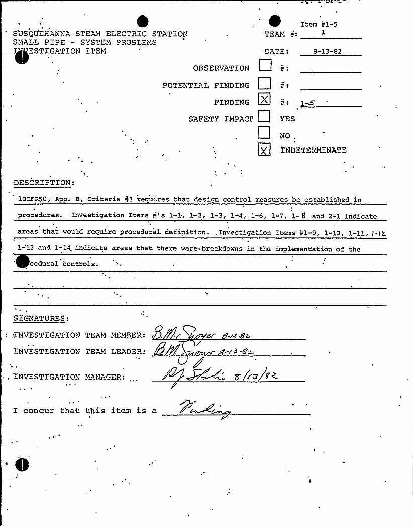
Item I1-5TEAM ~ 1
ESTIGATZON ITEM 8-13-82DA>E
OBSERVATION
POTENTIAL FINDING
FINDING X
SAFETY IMPACT YES
NO .
INDETERMINATE
DESCRIPTION:
10CPR50, App. B, Criteria 53 requires that design control measures be established in
procedures. Investigation Items 5's 1-1, 1.-2, 1-3, 1-4, 1-6, 1-7, 1- 8 and 2-1 indicate
areas that would require procedural definition. .Znvestig'a'tion Items I1-9, 1-10, 1-11, J-t2.
1-'13 and 1-14 indicate areas that there were- breakdowns in the implementation of the
cedural controls.
SIGNATURES:
INVESTIGATION TEAM MEMBER:
INVESTIGATION TEAM LEADER:
8r 8-r .8~
-r3 -Ox
. INVESTIGATION MANAGER:
I concur that this item is a
~ ~
s
/


Pg, or 2
Item Prl-6
SUSQUEHANNA STEAM ELECTRIC STATIONSi~ ALL P IP E - SYSTEM P ROBLEMS.I STZGATZON ITEM
TEL%
DAT": 8/13/82
OBSERVATION X
POTENTIAL F ZNDING
FINDING
SAFETY IMPACT
Cl ~
YES
1-6
No
INDETERMINATE
DESCRIPTION.-,
~ ~
There was no documented evidence to show that as-built ISO ISP-HCB-133-2 Rev. 8 was
formally transmitted to the RE Group for reconciliation. The program for As-Built approval
required the FE grouo to assemble a document package containing all as-built drawin s (Fab
1 and Hanger Details) related to an SKM, attach a transmittal form, ahd forward it 'to
the RE group. he RE rouo would then reconcile the Packa e, sian-off the documents and
advise FE.. The team was told that this drawing and approximatel 265 others were handled
by. handcarrying the revisions from Field Engineering to the RE Group and not by a
SIGNATURES:
INVESTIGATION,TEAMMEMBER:
INVESTIGATION TEAM LEADER:
5 /3
INiVESTIGATION V~AGER:
I concur that this item is ag


Item -"..i-6
transmittal form. The direction for tnis was given in a meeting be-tween the two groups.
As a result of not having a dated transmittal form there is no as-surance that the RE group had sufficient time to perform a substantivereview/reconciliation of the as-built packages.


~ or
S USQUEHANNA STEAM "LECTRXC STATIONSHALL PIPE - SYSTEM PROBLEMS
ESTXGATlON ITEM
I1-7
TE>2i
DATE: 8/13/82
OBSERVATION X
POTENTIAL FINDING
FINDING
SAFETY XMPACZ
~i ~
2! ~
)-7
NO,
INDETERMINATE
DESCRIPTION:
Calculation 55268 — Isometric SP"'HCB-109-1, Rev. 14; SP-HCB-109-2, Rev. 16. Sheet P6
of the above calculation shows that the span len th between suooort H2008
exceeds the maximum dynamic support span by 2". Auditor was told bv A. T. Morrow ofthe RE Support Group that overspans of up to 6 or 7 inches are sometimes allowed by
ineering judgement. 'Spec. M-241 does not indicate any tolerances are to be a nlied
to.the maximum support spans.
SIGNATURES:
INVES ~ IGATXON TEAM MEMQER:
INVESTXGATXON TEAM LEADER:
ez a~C. L. Dvorscak.
B. M. Swoyer
- r9ga
'I'NVESTIGATXON MANAGER: R. J. Shovlin
'I concur that this item is a> CP

Page 1 of 2
I ~ ' Item il-8SUSQUEHANNA STEAM ELECTRIC STATIONS~L PIPE SvSTEM PROBLEMSIFF=STZGATZON ITEM
TE~ <
DATE: 8/13/82
OBS"RVATZON
POTENTIAL FINDING
FINDING
SAFETY IMPACT
In:
4 ~I ~
YES
1-8
NO .
INDETERMINATE
DESCRIPTION:
SDecif ication 8856-M-241 Rev. 3 paragraph 4. 2.3. requires satisfaction of nrimar stress
allowables "b rovidin ~ d namic su orts on strai ht ipe at s acing less than or ecual to
the maximum allowable spans given in Appendix B tables B-l. 1 to B-l . 11. " Table B-l . 11 pre-
i m all wable span of 9 5'or 2" schedule 80 carbon steel 'pipe located in the
diesel generator rooms.
Contrar to .this requirement calculation F5418 sheet 3 does not consider maximum allowable
span for the followin oi e runs': 10'-3" s an between sup orts SP-HBC-78-7-H63 and H64;10'-0"
SIGNATURES:
INVESTIGATION TEAM MEMBER: 8/mrs~
ZNV"STIGATZON TEAM LEA'DER:
INVESTIGATION MANAGER: rP~
I concur that this item is aa

~(
E
~ ~
Item 51-8Page 2 of 2
span between supports Sp-HBC-78-7-H64 and H65>10'-0" span between supports
SP-HBC-78-7-H65 and H66~10'-4j" span between supoorts SP-HBC-78-8-H51 and
H52J 9 '-ll 3/4" span between supports SP-HBC-78;8-H52 and H53J 10 '0" span
between supports SP-HBC-78-8-H53 and H54. All six of these pipe runs have
spans in excess of the 9.5'llowable, by slight amounts.
Investigation indicates that these spans were within the length allowable
by an earlier, superseded revision of specification M-241.
As-built reconciliation calculation ABS-5418 does not address reconciliation
of these six overlength spans in clear fashion. Only 'a brief general
note, "Referenced computer output for calc. SABS-5416" is supoosed to
imply performance of this reconciliation. The investigation team was unable
to make that inference due to lack of sufficient detail in. this note(shown.
above). Only after a lengthy investigation was the team satisfied that the
above span lengths are adequate.
There appears to be no adverse safety impact resulting from this action.


T.tern- 5 l-e
~
~~
APPFN&ix —5IQN CR)7ERw 8P>(-8->t
PCVI Sioà 2
+~ Ns ~'s -g195 oF MX. OFAY
i,o -80 O.o 7.0j 0 225
I V~ 80
2Q-80 0 0 9 g

Item Nl"8
Design C" '856-M-241Revision 3 'I
APPe&ix B
XNS'LOCI'ICHS FOR UM OF TABL-„- B-l,ly
1 CALCIUM SILICATE USM AS INSULATION.
2. PIP WITH NAX7.R.
3 ~ MVZ~ SPAN FOR STRAIGHT PIPE IS BARD CH EESXGN P~~tJrK O." 2000PSI FRCH PIPING CEASS SQ'KQK K " TS WZTS CDNSIZKRAION OF U~EtKiGM Y AND FAUL~ ICED CCYBINKTION FOR GQU3CH ~i~ Q = %000PSI.
4, FORCM ~ FOR MAXIMUMSPAN AK) FOR 7~ W KQQMUM WAN AREKSIK FORC LCM'OR SUPEORZS AND NCKRS AND R~~V CGA)FORCES FRCH PIPING ON BClIH SIDES OF'AHMDR OR SUPP'. IF PIPESPANS OR PXP AND XNRJEATICM PRO~~ ARE NVr TiK SIP ON R7HiSIZES QF SUPPORT OR ANCHOR, OhE PELF 'DK TAKJLgQM VAU3=-S
APPLIC-'BLE
VD PIP~ CH EAM SIM SHCULD BE ADDED TO OBI'AIN TER ~I&iElRZS.
5. TiK TKEiIA~FO~ S ~TS AR ~ ON TER COhTBOLLXbG LMDCCMBImVZON OF (m + OBE). n-~ rmCS AR mr ZNaZ~.
6. ~ = 1.3 USED FOR S'~~S EVALUATION.
7. KERMIS Fi1CM FOR MAXQCJH SPAN AND FOR 75K CF MMQMUM SPM AREEKSX(K KN~S SCADS FOR ANCZBDRS AND ~~7 CDHBXhiD~ S
FRY P~ ON EVE SIZES CP T.:" ANCHOR. ZF PIP SPANS OR PIPEAND INSULATION PKPERFXES ARE H7I'" SAM" CH iKlZH SEES CF %"ÃZZOR, QHE HMZ 'QK TABULATED VALUE APPLICABLE TO PIPEh6 ON
'EACH SIDE SBX1LD BE ADDED TO OBTAIN TEA AN~ RESIDE ElRES
8. RES~ SPECTRA XNFORRTICH XS T~ FBCM CEVIL SPM ~ 885&G-24,RM. l.
P154/12-3
B-12m


Page 1 of 2
~ken ~ /-~/
SU UEHANNA STEAM ELECTRIC STATIONS. PIPE - SYS EM PROBLEMSIN STZGATION iTEM
r
T~r&1 ~ o
DATE: 81382
OBSERVATION m: /-0'OTENTIALF ENDING,. Pr:
FINDING
SAFETY IMPACZ YES
NO .
INDETERMINATE
DESCRIPTION:
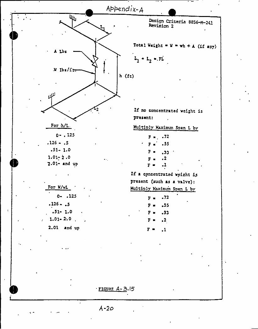
o i Air 4 ( v ooendix A ficure A-3.15 oresents ceometrv ad'ustment
factors for concentrated weights and.dvnamic loads for one ining geometry. As the figure
is self exolanator , no-additional. instructions are provided for its use. The figure states,
"F /WL = 0.51 to 1.0 ... Nultiply maximum span L by F 0.33."
Contrary. to this, calculation I5268 (Rev. 2), sheet 4, span "H2000 to H2011" shows for W/WL =
0.78'... multiol'cation of maximum span L b F = 0.42. lnvestiaation indicates that this
'alu'e of F was obtained bv interpolation of the values for F given in figure A-3.15. Such
SiGNATURES:
Z~i STIGATION TEAM MEMBER: ri/we~ZNVESTZGA'TION TEAM LEADER:
INVESTIGATION MANAGER:I
I concur that this item is a>

(I
~ ! ~
Page 2 of 2
X'+e.m )-5"
interpolation of the values for F presented in Figure A-3.15 are not authorized
within the specification. Application of this larger value for F, obtained by
interpolation, resulted in acceptance of a 2'-5$ " span, which should have been
identified as being 4$ " overlength, by spec M-241 criteria.q'here appears to be no adverse safety impact resulting from this action.
885~2'~isbn 2r
Total MeiZht ~ M ~ eh + g (gf a~)
.9 lbs/ih (ft)
Ll + L2 ~,FL
For h/L.
0-, 125
. 126 .5.Sl- 1.0
1.01- ) .0>.Ol- and up
For N/xL
0- ~ 125
.126- .5~ Sl- 1.0
1.01- 2;0
2.01 and up
If no concentrated xeight ispresent:
Hultia1 Maxim . Soan L b
F s .72
F ~ '55F ~ ,33F g ~ 2
Fe ..1
If a concentrated veizht ippresent (such as a valve):Multi@1 Raxiamw Span L bv
F a ~ 72
F a +55
F s .33
F s ~ 2
F a ]


~' s
SUSQUEHANNA STEAM ELECTRIC STATIONSHALL PIPE — SYSTEM PROBLEMSI
ESTIGATION ITEH
TEAM
DATE: 8/13/82
OBSERVATION X I: I-xo
POTENTIAL FINDING
FINDING Pr
SAFETY IMPACZ YES
NO,
INDETERMINATE
DESCRIPTION:
Support SP-HBC-78-8-H2041, as shown on. the as-built support detail drawing, shows the
pipe running along the north-south direction. The pipe actually runs along the east-
west d'irection.
SIGNATURES:
INVESTIGATION TEAM HEHQER:
INVESTIGATION TEAM LEADER:
e.e. 8~C. L. Dvorscak g- 13-8'A
B. M. Swoyer
INVESTIGATION MANAGER: R. J. Shovl in*
'a <~8~z
I concur that this item is an C5
~ ~

Pg. 1 of 1
I - II
SUSQUErIAMNA STEP"I ELECTRIC STATIONS. LL PIPE - SYSTEM PROBLEMS
STIGATION ITEM
T" AM
DATE: 8/13/82
OBSERVP<ION XP J -/I
POTENT'IAL FINDING I:FINDING
SAFETY IMPACT YES
NO .
INDETERMINATE
DESCRIPTION:
Calculation I5499 — Xsometric SP-HCB-133-1, Rev. 16., Sheet I9 of the above
calculation shows the minimum span reguired to accommodate oiping thermal expansion
and diffe&tial building movements. This calculation does not correctly account for
differential building movements as per Spec. M-241.
SIGNATURES:
,INVESTIGATION T"AM MEHQER:c.y S~C. L. Dvorscak - / - 2
INVESTIGATION TEAM LEADER: B. M. Swoyer
INVESTIGATION MANAGER: R. J. Shovlin g/DCS w
I concur that this item is aw

Pg. 1 of 2
.e )-/2
TEAMSUSQUEi'.ANNA ST"AM EX.ECTRIC STATIONSMALL PIP — SySTEM PROBLEMS~
~
STIGATZON ITEM 8/13/82DATE:
OBSERVATION x z .'-/2POTENTIAL FINDING
FINDING
SAFETy IMPACT yES
X NO,
INDETERMINATE
DESCRIPTION:
Calculation 55268 - Zsometric SP"HCB-109-1, Rev. 14; SP-HCB-109-2, Rev. 16. Sheet I5
of the above calculation shows the reauired span length between H2000 and H2002.
~engineering judgement was used in the distribution of load between the two supports. (See
attached for details). The same type of assumotion was applied to the span calculation
be ween penetration X-221A and H2011. Spec. M-241,, Rev. 3 does not indicate any
tolerances can be applied to the above condition.
SIGNATURES:
INVESTIGATION TEAM MEMBER:
INVESTIGATION TEAM LEADER:
c..e. S~C. L. Dvorscak
M. - iz -8~k
INVESTIGATION MANAGER: R. J. Shovl in
I concur that this item is a~
~ ~


The span between H2000 and H2002 can be represented as shown below.
g [ /ROOFS.
.r
The calculations indicate that all of the dynamic loads associatedwith the concentrated pipe and valve weights is taken by H2000.Strict interpretation of Spec. M-241, Rev. 3 would indicate thatthe load should be split up between the both supports and the spanadjusted accordingly.
Spec. M-241, Rev. 4 provides direction for this type of condition,that is, when all the load can be lumped on one support and notsplit up. The calculations noted above appear to go beyond theseguidelines also.
~y e I-IQSUSQUEHANNA S 'AM ELECTRIIC STATIONSMALL PiPE — SYSTEM PROBLEMSI STZGATION ITEM
TEVl
8/13/82DATE:
OBSERVATION X 1-lS
POTENTIAL FINDING
FINDING
SAFETY IMPACZ YES
NO .
INDETERMINATE
DESCRIPTION:
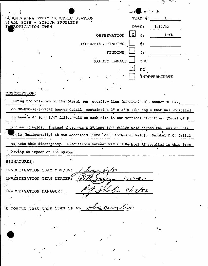
During the walkdown of the Diesel gen. overflow line (SP-HBC-78-8), han er NH2042,
on SP-HBC-78-8-H2042 hanger detail, contained a 3" x 3" x 3/8" ancle that was indicated
to have a 4" long 1/4" fillet weld on each side in the vertical direction, (Total of 8
inches of. weld). Instead there was a 3". lone 1 4" fillet weld ac~os
gle (horizontally) at two locations (Total of 6 inches of weld). Bechtel Q.C. failed
to note'this discrepancy. Discussions between NPE and Bechtel RE resulted in this item
having no impact on the system.
SIGNATURES:
INVESTIGATION TEAM MEMBER:
INVESTIGATION TEAM LEADER:
INVESTIGATION MANAGER: g pg 72.
I concur that this item is aw

Page 1 of 2
I>
o I
SU QU HANNA STEAN ELECTRZC STATZONS L PZP SYSTEM PROBLEMSZ STZGATZON ZTEH DATE: 8/13/82
OBSERVATZON
POTENTiAL FZNDZNG
FZNDZNG
SAFETY 'ZHPAC1
2 ~
4 ~
YES
NQ .
ZNDETERHZNATE
DESCRZPTZON:
f nces fabrication isometric
8VQ 1 B-109-2 Rev'. 7 as its sources of data.
ation 45268 utilizes sun orts SP-HCB-109-1-H2010 and H2011 (on pages 3, 4, 8, 9, 25,
These suooorts were not depicted .on approved revision 9 of this iso. .The following
revision 10 to this iso drawing, which added these two supports, was not, issued until
8/06/81. This use of other than an approved iso appears to be contrary to the requirement
of specification 8856-M-241 paragraph 2.3.
S ZGNATURES:
ZNVESTZGATZON TEAM MEMBER: rJ(st<~
ZNVESTZGATION TEAN LEADER:
ZMi ESTZGATZON MANAGER: 8r~ IZ
i concur that this item is aw

Page 2 of 2
XVc~ sr /-/r/
There appears to be no aaverse safety impact resulting from this action.

I
~ Q I
Page 1 of 2a'he~ w 1 - 15
SUSQUEHANNA STEM4 ELECTRIC STATIONPIP" — SYSTEM PROBLEMS
INSTIGATION ITEM
TEAM
DAT": 8/13/82
OBSERVATION X
POTENTIAL FINDING
FINDING
SAFETY IMPACT
2 ~lt ~
JL ~
4 ~
1-15
NO
INDETERMINATE
DESCRXPTXON:
Three .items were found during the walkdown of the Diesel Generator Overflow Line (SP-HBC-78)
that would indicate there- might be an oversite in the. area of additional work performed
(like repair) after the System has been turned over or after final inspection. It is PP&L's
an echtel's responsibilities to make the a ro riate eo le aware of an areas that re uiregt4AL e
any additional design review or inspection. The three items are: .(1)~no clearance between
the. pipe and unistrut at a point approx. 2'est of hanger 8H53~was repaired (shimmed and bolts
tightened) under the SP600 Hanger repair program.
SIGNATURES:
INVESTIGATION TEAM MEMBER:
INVESTIGATION TEAM LEADER:
INVESTIGATION MANAGER:,
concur that this item is a 0

0

t ~ /-)aPage 2 oz 2
(2) A conduit was supported by being clamped to piece of unistrut. This
unistrut was supported by being clamped to the Diesel Gen. Overflow line.
This work is done afte" turnover.
(3) On Hanger H2047, one of the anchor bolts on the baseplate attached to the
wall had the torque paint removed. The Bechtel QC documents had veri ied that
the torque paint was intact prior to turnover A second bolt, although extendinp.
slightly above the nut, allowed two threads in the nut to be visible. This
condition was a result of the taper at the end of the bolt.

il2-ly Page 1/3
SU~~HANNA STEP% ELECTRIC STATION:-'A~ PIPE — SYSTEM PROBLEMSINVESTIGATION ITEM
TEM
8/13/82
OBSERVATION
POTENTIAL ."INDING
FINDING
SAFETY. IMPACZ
OII
YES
NO .
INDETERMINATE
DESCRIRTION:
Please refer to 'attached.
SIGNATURES:
INSTIGATION TEAiM PLUMBER:~MEMBER
I~i STIGATION TEAN LEADER:~INVESTIGATION TEAN LEADER
INVESTIGATION MANAGER:
8/9 gz
s'I/9/g k
8 r3 az.
I concur that this item is a
0I
'Page 1 of 3

Page 2-1 Page 2/2
Aug. 13, 1982
Team 82
SUSQUEHA.WA STEAM ELECTRIC STATIONSKKL PIPE — SYSTEM PROBLEMS
INVESTIGATION ITEM
DESCRIPTION:
Field Procedure P-ll, Rev. 6, Section 6.2.7.1 outlines the requirements for theissuance of SP and SPA Details.
The proc dure is as follows:
1. The SP and SPA Details are received by'he site Print Room from SFHO.
-2.. The Print Room logs one copy into a suspense file and forwards one copyto the Lead Field Small Pipe Hanger Engineer for review and comment.
3. The LFSPHE then forwards the document to the Lead Field Welding Engineerfor review and comment.
4. The LFWE then returns the document to the Print Room for appropriatedistribution to the field, i.e. one copy to the Resident Engineer Group.
Contrary....to the procedure, the L'FSPHE did not forward 274 SPA drawing revisions whichhe received in January, 1982. Although the procedure does not specify a time limitfor the above routing activity, a seven (7) month delay violates the .intent of theprocedure.
Bechtel JAR i/8856-F-859 (copy attached) was issued on 7/30/82 to expedite correctiveaction.
The LFSPHE stated that he "sat on" the SPA's because the field design work wasessentially complete at the time he received them, and that the SPA's are used fordesign guidance (Ref: FP-P-11, Rev. 6, Sect. 6.2.5).
'In discussions with the LFSPHE, he stated that the SP and SPA Details were seldomincorpora'ted as-is in the field, since as construction progressed and the plantbecame more comples, standard details became difficult to apply in the plant.Therefore, unique hanger drawings ere developed for each hanger in the plant. Thesmall pipe hanger group generated .the unique drawing, the field installed the hangeron a "risk" basis, and it wasn't until Project Engineering accepted the installedas-built hanger that the "risk" was removed. These steps are described in FP-P-ll,Rev. 6 and M-213 Rev. 11.

IJII
1~ A
I/2-2 Page 1/
SU~EHANNA STEAN ELECTRIC STATIONS? 1RPb PIPE — SYSTEM PROBLEMSINVESTIGATION ITEM
TEAM
DATE . 8/12/82
OBSERVATION 5:
POTENTiAL FINDING X
FINDZNG
SAFETY IMPACT YES
x NO Resolution of "potential fn~.'ould change.
INDETERMINATE
DESCRIPTION:
Bechtel specification 88S6-M-213, Rev. 11, appendix F contains Project Engineering
definition of the attributes of pipe hangers requiring QC inspection and provides
the acceptance criteria. Appendix 'F fails to include friction hanger clamp ear gaps
as an attribute to be inspected to'ssur'e adequate gripping of the pipe by the clamp.J
k
This attribute is not identified in any other documents used by QC forinspection.'onsequently,
numerous "detail 600" clamps (friction type) .have been installed without
'QC inspection of the clamp ear gaps (Ref. Bechtel FCR-4066, PL-NCR 82-728). The
SIGNATURES:Bechtel FCR does not request a change to Appendix F of M«213.
ENVESTIGATION TEAM MEMBER:
INVESTIGATION TEAN LEADER:
INVESTIGATION MANAGER:
I concur that this item is a Findin


Page 1/182-3
SUSQUEHANNA STEMS ELECTRIC STATION.PIP" — SYSTEM PROBLEMS
Z~TZGATXON ZT
TEAM
DATE: 8/13/82
OBSERVATION X
POTENTIAL FINDING
FXNDlNG
SAFETY iMPACT
INDETERMINATE
DESCRIPTION:
Han er drawin SP-HBC-78-H53; Revision 1, Field Revision 3, indicates the location of
Hanger, Number H65. (For reference only). But .the drawing erroneously indicates the
hanger number as H69. The proper hanger is installed in the field. Considering the
n ~ of "evisions, reviews, and inspections, this error should have been corrected.
SlGNATURES:
Z~i STIGATXON TEAM PKMBER:
iNVESTEGATXON TEAM LEADER:
"NVESTlGATiON 'MANAGER:
i concur that this item is an

k
4
It2-4 ~ Sheet' of 2
«U~~HANiNA STEAM "LECTRICSTATION'-:w~
PIPE — SYSTEM PROBLEMS I
NVESTIGATION 1TEM DATE: 8/13/82
TERA I'. 2
OBSERVATION
POTENTIAL FINDING
FINDING
SAFETY INPACZ X
r. ~
2 ~1J ~
YES
NO
INDETERMINATE
DESCRIPTZOH:
S ecification 8856-M-213 "Technical S ecification for Installation Ins ection andP t P p
Documentation of pipe supports, hangers and restraints" does not provide criteria with regard
to installation and inspection for all vendor fabricated components such as "Detail 600"
and''swa struts.
Examples:
1... There is no'nspection criteria regarding the gap requirements on installed "Detail 600"
Some of these were found to have no gap as documented in NCR No.. 82-728 (PP&L's)
"=IGNATURES:I
ZbVTESTIGATION TEAM MEMBER:
INVESTIGATION TEAM LEADER:PAe ~e,cleric cowJu'bio< gra~rr fro~ /he
I~i STZGATZON MANAGER-
ldll L serlcckorg reg'o,v J i qJ gI C CA~~Pc'4 A%7 cd:"
rz ~"~
E concur that this item is a Finding based on the generic implications of not
utilizing ve'ndor information for inspections (not spelled out as a requirement in a QCIR),
niche'wo examples cited.

82-4
8-13-82 Sheet 2 of 2
2. There is no criteria for installation and inspection of sway struts. Thesestruts are a complete vendor supplied assembly with jam nut(s). The vendorhas specific requirements covering how to install the sway struts and how totighten the jam nut(s) . Yet many struts are found that have their nut(s)not tightened properly as is documented in PP&L HCR 82-794.

Page 1 of 2
ATTACHMENT BDOCUMENTS REVIEWED BY THE INVESTIGATION TEAMS
1. "As-built" Fabrication Isometric PSP-HBC-78-8 and associated"as-built" Hanger Detail Drawings — Diesel Generator Over-Flow Lines.
2. "As-built" Fabrication Isometrics f/SP-HCB-109-1 and PSP-HCB-109-2 andtheir associated "as-built" Hanger Detail Drawings - Wetwell Atmo-sphere Sample Supply Lines.
3. "As-built" Fabrication Isometrics ESP-HCB-133-1, //SP-HCB-133-2, and//SP-HCB-133-3 and associated "as-built" Hanger Detail Drawings—Suppression Pool Water Level Instrumentation Lines.
4. "As-built" Fabrication Isometrics !ESP-HBD-1538-1 and associated"as-built" Hanger Detail Drawings - Instrumentation Drain from 1"HCB-133-1 to Floor Drain.
5. "As-built" Fabrication Isometric PSP-GBB-102-2 (no hanger) — DrainLine from Core Spray Pumps Suppression Pool Instrumentation LineStress Isometric, SK-M-5499.
6. Diesel Genexator Over-Flow Line Stress Isometric, SK-M-5418.
7. Wetwell Atmosphere Sample Supply Line Stress Isometric, SK-M-5268.
9. Drain Line from Core Spray Pumps Stress Isometric, SK-M-5158.
10. Calculation f/5418, Diesel Generator Over-Flow Lines and associated"as-built" reconciliation calculations (ABS 85418 and ABH 85418).
I
Calculation //5268, Wetwell Atmosphere Sample Supply and associated"as-built" reconciliation calculations (ABS //5268 and ASH f/5268).
12. Calculation 85499, Suppression Pool Water Level, and associated"as-built" reconciliation calculations (ABS f/5499 and ABH //5499).
13. The SP/SPA Drawing Book.
14. Stress and Thermal Walkdown Records for "as-built" Fab. Iso. fl'sSP-HBC-78-8, SP-HCB-133-1, SP-HCB-133-2, SP-HCB-133-3, SP-HBD-1538-1,SP-HCB-109-1, and SP-HCB-109-2.
15. ualitv Contxol Documentation Sam led
QCI P-1:00 Verification of ASME III Documentation and N-Type CodeSymbol Stamping
Page 2 of 2
QCI P-1.10 Piping Subassembly Fabrication, Installation andRework
QCI C-1.10 Installation of Grouting and Drypacking
QCI C-1.50 Installation and Testing of Expansion Anchors
QCI P-2.00 Pipe Hanger, Support, Restraint and Shock SuppressorInstallation — Final Review
QCI P-2.10 Pipe Hanger, Support, Restraint and Shock SuppressorInstallation
QCI T-1.00 Hydrostatic, Pneumatic and Preoperational In-ServiceLeak Testing
IRs were reviewed and associated with the above QCIs as applicable for theDiesel Fuel Oil Transfer Pipes as defined on Field Fabrication Isometricand for all (14) the hangers associated with that Isometric (SP-HBC-78-8).
WR-5A forms were reviewed for each weld on the piping system (IsoSP-HBC-78-8) for 2'Inch and Less Socket Welds.
WG:lecGA-7