Embed Size (px)
Citation preview

environment.act.gov.au
Surveyor-General of the Australian Capital Territory
Guideline No.2 – Cadastral Control Surveys
In the event of an inconsistency between these guidelines and any Act, Regulation or Direction, the Act, Regulation or Direction takes precedence.
1.0 IntroductionCanberra benefits from one of the world’s best cadastral systems. The close link between the cadastral framework and the survey control network provides efficiencies in many areas of design and construction. Other Australian jurisdictions are spending millions of dollars attempting to establish similar systems. These guidelines are intended to assist surveyors understand the requirements established to maintain this valuable link between the cadastre and the control network.
The guidelines have been prepared to assist Surveyors who are required to connect to and/or place survey Coordinated Reference Marks, pursuant to Sections 35, 38, 39 & 43 of the Surveyors (Surveyor-General) Practice Directions (SPD). They outline the standard of accuracy expected for coordinates, and the recommended field practices required to obtain that accuracy. They also give further guidance on connecting to existing survey control marks.
These guidelines should be read in conjunction with the current version of the SPDs and the Standards and Specifications for Deposited Plans.
2.0 Coordinated Reference Marks (CRMs and SRs)
2.1 Coordinated Reference Marks (CRMs)
SPD 43(4) requires Coordinated Reference Marks (CRMs), to be placed along roads at intervals of not more than 150m throughout the length of the land surveyed. In greenfield subdivisions the installation and coordination of CRMs as defined in SPD 35 is the responsibility of the Surveyor.
The Surveyor will supply the Surveyor-General with a copy of a plan of the development area showing the road pattern, section numbers and the proposed location of CRMs and SRs. The Surveyor-General will review the proposed CRM and SR locations. Upon approval, the Surveyor can then purchase the appropriately numbered CRM plaques and SRs from the Environment and Sustainable Development Directorate (ESDD).
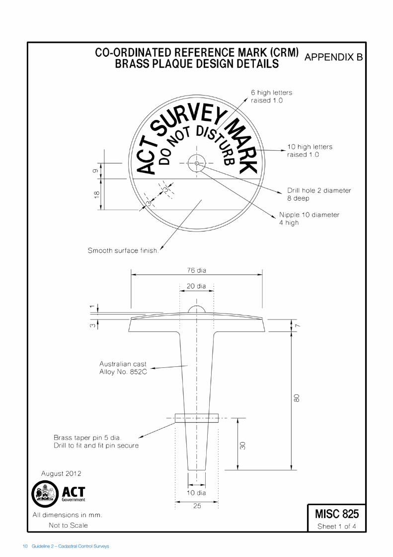
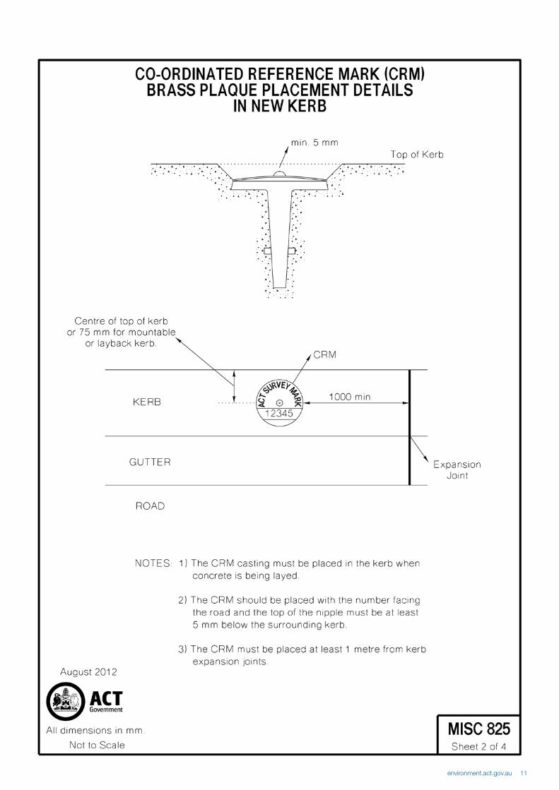
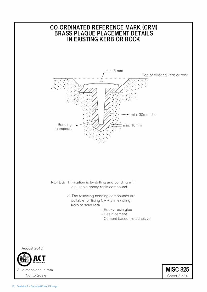
CRMs must be placed in new kerb in accordance with plan MISC825, (a copy of this plan is attached as Appendix B) and are to be:
• located at least 1m from any expansion joint and in an area away from cracks;
• not more than 150m apart (SPD 43(4));
• placed such that no part of the CRM, including the raised nipple, is above the surrounding concrete;
• placed such that clear lines of sight will exist after nature strip trees have matured; and
• placed in consideration of the long term stability of the mark and the safety of surveyors using the mark in the future.
SPD 37(4) requires that coordination of CRMs is not to be carried out until kerbs are completely stable, i.e. final road surfacing and consolidation of earth works behind kerb lines must have been completed.
SPD 43(6) requires the Surveyor to determine the AHD71 reduced level of all CRMs.

2 Guideline 2 – Cadastral Control Surveys
2.2 Steel Rod (SR) Mark Requirements
2.2.1 SPD 43(3) requires that stable survey marks of a type described in either SPD 35(b) or 35(c) be placed at approximately one mark for every 100 blocks in subdivisions of land. For the purpose of this Guideline, deep driven steel rods (SRs) are defined by SPD 35(c) as a special type of CRM. SRs form a stable framework for horizontal position and level after the development has been completed.
As of 1 July 2014, Surveyors will be responsible for the positioning and construction of SRs in greenfield subdivisions, as well as their horizontal and vertical coordination. Although the precise levelling of SRs to Class LA standards will be the responsibility of the Surveyor-General, SRs must be included in the Surveyor’s Class LC levelling networks.
Each SR shall be located and constructed in such a fashion that its long-term stability, usability and safety is maximised. SRs must be placed in accordance with plan MISC827 (a copy of this plan is attached as Appendix C).
As part of the survey plan examination process, the positioning and construction of SRs will be regularly audited for compliance with this Guideline. Failure to comply may result in a delay in plan processing while the surveyor rectifies any problems disclosed by the audit.
2.2.2 The following items must be considered for each SR placed:
a. The mark shall be accessible to allow for its proper use and be located in a position fit-for-purpose;
b. The location of all nearby underground utilities must be verified prior to the construction of the SR;
c. The chosen SR position must comply with minimum setbacks, as specified by each utility provider;
d. Be located in a position that minimises any danger to future users;
e. Be positioned at a minimum of 0.9m from the back of kerb;
f. Be installed in stable ground, such that it will not be subject to local displacement or other seasonal or periodic movements;
g. Should have clear line of sight (both current and future) to adjoining CRMs and to distant trigonometrical stations; and
h. Have a sky view with minimal obstructions above 15˚ above the horizon, to support GNSS surveying techniques;
2.2.3 The construction of each SR shall comply with the following requirements:
a. All components of the survey mark are to be made of high quality, durable and corrosion resistant materials;
b. Robust construction techniques shall be employed;
c. A copy of the latest underground service plans must be supplied to the person(s) placing each SR;
d. Each 2m long stainless steel rod is to be driven to its full length, or driven to refusal to a minimum length of 1.1m;
e. To avoid the risk of being a trip hazard, the top of the SR cover box and the surrounding concrete collar must be flush with the surrounding surface; and
f. To ensure unambiguous identification, the mark identifier shall be stamped on a durable, non-corrosive metal tag and placed in the wet concrete collar during installation.
2.3 Connection to Established Survey Control
‘Established Survey Control Mark’ means a survey mark that has a horizontal positional accuracy equal to or better than Class C as defined in SP1 v1.7. In accordance with SPD 39 and 45, Surveyors are required to connect to established survey control marks that are within 200m of the land being surveyed, to ensure:
• The link between the survey control network and the cadastral framework is maintained and enhanced; and
• CRM coordinate values can be established, or verified, while connecting the marks to the cadastre.
The connections referred to in SPD 45 shall include at least two (2) established survey control marks, with an angular confirmation of the datum orientation to a third mark. The third mark may be a distant trigonometrical station.

environment.act.gov.au 3
It is acknowledged that complying with these directions may be impractical in some areas of the ACT. Surveyors are therefore encouraged to seek advice from the Surveyor-General if they are unsure of their obligations.
2.4 AccuracyClassifications
ICSM Publication No.1 Standards and Practices for Control Surveys (SP1) version 1.7 recommends accuracies and procedures for survey observations and uses Class and Order to classify the accuracies of all types of control surveys. The Surveyor-General has determined that coordinates of horizontal control marks placed for cadastral surveys must meet SP1 v1.7 Class C Order 3 standards of accuracy.
SPD 43(6) requires that the levelling of control marks placed for a cadastral survey must meet SP1 v1.7 Class LC standards of accuracy and that the results be supplied promptly to the Surveyor-General.
When the Surveyor has coordinated the CRMs and SRs, the Surveyor-General will have the details of all survey marks entered into Control Base and made available to the public via ACTMAPi.
3.0 Horizontal Control Procedures
3.1 Responsibility
The Surveyor will ensure that there is an adequate density of survey control in or adjacent to the area of development, and that the existing control meets Class C Order 3 standard of accuracy or better. If it is found that the published coordinates of the existing control network do not meet these standards, the Surveyor should notify the Surveyor-General at the earliest opportunity.
Any additional survey control required to comply with the SPDs will be at the Surveyor’s expense.
3.2 Accuracy of Horizontal Control
The horizontal coordination of control marks placed for a cadastral survey must, as a minimum, meet SP1 v1.7 Class C Order 3 standards of accuracy.
3.3 Observation Requirements
Sufficient observations to new control marks, along with sufficient redundancies, are to be measured to coordinate the new CRMs and SR marks. Additional observations between local control marks and to distant trigonometrical stations, over and above the traditional closed traverse, are highly recommended. The observations should then be adjusted using a least squares computation program or other approved method of adjustment.
The following field practice is recommended:
• All horizontal angles, directions or bearings should be determined by two (2) rounds of face left/face right observations. If the difference between the two rounds exceeds 15”, then another round should be observed to determine which round to reject.
• Ambient temperature and atmospheric pressure should be observed before each distance observation, recorded in the field notes, and the resulting first velocity (ppm) correction entered into the EDM. General weather conditions as observed should also be noted in the field book.
• All distances should be measured in both directions. A minimum of six (6) individual observations should be measured in each direction. If the difference between the forward and reverse distances is greater than 4mm + 20ppm, the distance should be independently re-observed to determine which observation to reject.
• Observations between control marks must be performed using forced centring methods (i.e. plumbing poles are not to be used).
3.4 Network Connections
Section 2.3 above and SPD 45 require surveys to be connected to the existing control network if established survey control marks lie within 200 metres of the survey site. This connection should be in accordance with the requirements below:

4 Guideline 2 – Cadastral Control Surveys
• All control marks shall be included in a closed survey network. No mark, including CRMs at the head of a cul-de-sac, should be left “hanging” at the end of a radiation. A connection to the cadastre shall not be used to close a survey network.
• New CRMs and SRs should be enclosed on all sides by a network of established control marks. The more established control marks that are included in the survey network, the better the adjustment can be fitted into the existing control.
• All new and existing local control marks are to be occupied, and have observations made from them, to adjacent control. No mark, with the exception of distant trigonometrical stations, should only have observations to it (i.e. radiated from one or more marks).
3.5 EDM Calibration
Electronic Distance Measuring (EDM) equipment used in the establishment of horizontal control marks must be verified at least once every 12 months on a certified baseline pursuant to SPD 17(2). The Surveyor-General maintains an EDM baseline at Watson. Surveyors wishing to use the EDM baseline should refer to the EDM Calibration Handbook for more information. Contact the Surveyor-General (ph: 6207-1639) to make a reservation to use the EDM baseline.
The additive constant, scale error and cyclic error, as determined by the EDM calibration, shall be applied to the observed distances prior to the network adjustment.
3.6 GNSS Equipment
Surveyors choosing to use GNSS techniques to establish control for cadastral surveys must follow the procedures described in Surveyor-General’s Guideline No.10: GNSS and Cadastral Surveys.
Pursuant to SPD 17(3) GNSS equipment used in the establishment of horizontal control marks must have been verified on a GNSS test network or on an approved geodetic network within the 12 months preceding the survey. The Surveyor-General maintains a GNSS test network that incorporates the Watson EDM baseline. Surveyors wishing to use the GNSS test network should refer to Surveyor-General’s Guideline No.9: GNSS Equipment Verification and contact the Surveyor-General (ph: 6207-1639) to make a reservation to use the GNSS test network.
3.7 Plan of Survey
Connections between the new CRMs and SRs, along with connections to existing control marks and to the cadastre, are to be shown on the plan of survey (the X Plan) in accordance with SPDs 39(a)(i) & 62(c) and the Standards and Specifications for Deposited Plans.
The derived coordinates of the CRMs and SRs will be shown on the plan of survey in accordance with SPD 39(a)(ii) and the Standards and Specifications for Deposited Plans.
As well as showing the above information on the plan of survey, it is recommended that the Surveyor make a separate survey control plan showing all observed angles and distances and derived coordinates. This plan may be lodged with the Surveyor-General who shall keep a register of such plans. Such plans are invaluable for the resolution of discrepancies between surveys. Lodgement of a control plan does not excuse the Surveyor from the obligation to keep original field notes pursuant to SPD Division 6 but a comprehensive control plan will generally make it unnecessary for the Surveyor-General to require the Surveyor to submit field notes.
4.0 Vertical Control Procedures
4.1 Responsibility
The vertical control framework within the ACT consists of a series of precise levelling networks and traverses linking Permanent Bench Marks, SR marks and Sectional Control marks to which the CRM network and the old Kerb Bench Mark network is tied by Class LC levelling traverses.
The Surveyor is responsible for the differential levelling of CRMs and SRs within land developments as required by SPD 43(6). By virtue of SPD 43(6), the levelling of CRMs is a survey under the Surveyors Act 2007 and SPD 14 – supervision applies equally to the vertical and horizontal survey of CRMs.

environment.act.gov.au 5
4.2 Equipment
All levelling shall be carried out with modern automatic collimation levels in good working order.
Levelling staves should be calibrated regularly, with particular attention being paid to the stability of joins between staff sections. Similarly, staff bubbles are to be checked regularly, to ensure the verticality of the staff.
As an interim measure between staff calibrations, the Office of the Surveyor-General has established a levelling test network at the Watson EDM baseline, comprising of six SRs, enabling Surveyors to perform a system test on their levelling equipment and technique.
Contact the Surveyor-General (ph: 6207-1639) to make a reservation at the levelling test network .
4.3 Network Design
The Surveyor shall connect their new CRMs and SRs into existing control marks that surround their survey network, even if the control marks are some distance from the development. The cantilevering of a new levelling network off the side of an existing network is considered poor survey practice. Spur lines, spur loops and single check lines (legs into which no adjustment will be placed) are to be kept to a minimum.
The levelling network shall be designed so that the route between CRMs will be kept as short as possible and shall strive for the minimum amount of vertical separation. Levelling loops should generally follow the road network, with the inclusion of some additional lines to form closed figures.
The Surveyor should seek advice from the Surveyor-General if they encounter any doubt or difficulty with the design of their levelling network.
4.4 Collimation
A collimation test (two peg test) shall be carried out each day before levelling commences, and is to be recorded in the numbered level book (see 4.14). The collimation error of the level must not exceed 2mm over a distance of 40m, and is to be re-observed and recorded after any adjustment.
4.5 Accuracy of CRM Levelling
The levelling of CRMs and SRs placed for a cadastral survey must meet SP1 v1.7 Class LC Order L3 standards of accuracy.
4.6 Datum Marks
The datum marks will be Trigonometrical Stations, Sectional Control marks, SRs or existing CRMs, KBMs or RBMs. Subdivision Reference marks (SRMs) are not to be used as datum marks unless they have a vertical accuracy of class LC or better.
The levelling network must connect into a minimum of three (3) existing bench marks, which have AHD71 heights with a vertical accuracy of Class LC Order L3 or better.
The maximum allowable discrepancy between original and observed height difference between existing bench marks shall not differ by more than 12√K mm (where K is the distance in kilometres between the bench marks measured along the levelling route). Where this discrepancy exceeds 12√K mm, then additional levelling connections to other existing bench marks must be performed, until agreement is found between a minimum of three (3) marks.
4.7 Variations
A surveyor using existing control marks and discovering variations, either physical or mathematical, should report such variation to the Surveyor-General as soon as possible.
4.8 Allowable Misclose
The maximum allowable misclose of two level runs of each section between CRMs shall not exceed 12√K mm (where K is the distance in kilometres between the CRMs measured along the levelling route). Circuit closures shall not exceed this same limit.

6 Guideline 2 – Cadastral Control Surveys
4.9 Length of Sights
The length of any levelling sight should be such as to permit the certain reading of the staff, and shall never exceed 80m for CRM levelling. The lengths of foresights and backsights shall be measured and, as near as practicable, shall be of equal length. The total length of backsights should in no case differ from the total length of foresights between bench marks by more than 2% for Class LC levelling.
4.10 Temperature and Refraction
All sight lines shall clear the intervening ground between level and staff by at least 0.30m. Staff readings of less than 0.300m will not be accepted. Levels shall only be taken when atmospheric conditions allow reading the staff with certainty. If unfavourable conditions are encountered, the length of sight shall be reduced until certainty can be achieved, or the work discontinued.
The ambient temperature shall be recorded, together with the time of reading, at the commencement of each new page of observations. If levelling is performed in temperatures markedly different from the standard for the staves being used, in an area of large elevation differences, and especially a combination thereof, corrections should be applied to staff observations. These corrections should be applied according to the composition of the staves or by applying the staff scale factor, as determined by its most recent calibration.
4.11 Units of Measurement
All readings shall be recorded in metres to a minimum of 3 decimal places of a metre for Class LC levelling.
4.12 Change Points
Change points should be checked for stability, both vertical and lateral, and be of such nature as to have a definite high point. All CRMs, SRs and datum marks must be observed as change points.
4.13 Lines of Levelling
The levelling of each section shall be carried out twice, once in each direction between marks, and preferably at substantially different times (e.g. one way in the morning and the reverse in the afternoon).
4.14 Level Books
The Surveyor-General will provide numbered level books to the Surveyor, which will be returned to the Surveyor-General at the completion of the levelling.
4.15 Records
All level observations and relevant survey observations - taken in the field - are to be neatly recorded in ink in the numbered level book. Reduced levels or results deduced from field records are to be recorded in pencil. Only original notes will be accepted and transcription of original notes is expressly forbidden.
Notation in level books, other than actual observed readings, is to be neatly made in pencil to avoid confusion with field readings. No field notation is to be over-written. Incorrect readings may be lightly ruled through in ink, with the corrected field reading noted in ink on the next line below the cancelled reading.
When digital levels are used a complete hard-copy output of the each level run will be supplied to Surveyor-General, along with a copy of the raw data files and reduced (or formatted) data.
When levelling fails to reach the specified accuracy and is repeated, an entirely separate record is to be entered in the level book and appropriate cross-references made. Complete re- levelling must be done for the complete section between bench marks.
Subject to specific approval by Surveyor-General, if re-levelling on one direction agrees satisfactorily with either of the previous two level runs, the work may be accepted.

environment.act.gov.au 7
4.16 Use of Automatic Collimation Levels
Tripod legs must always be set firmly so as to ensure complete stability during observations. Each time the level is set to take readings, the dislevelment indicated by the circular bubble shall not exceed the tolerance laid down in the manufacturer’s handbook. The circular bubble must be in precise adjustment at all times.
To mitigate against systematic error due to dislevelment of the horizontal plane definition, the following routine is to be followed:
• ensure that the circular bubble is in the correct adjustment and level carefully at each station; and
• at consecutive bays, level the instrument with the telescope pointing in opposite directions. For example at 1st and 3rd stations the telescope should point towards the backsight, and at the 2nd and 4th stations the telescope should point towards the foresight when levelling the instrument. When staff persons are “leap frogging”, this is resolved by always pointing the telescope to the same staff when levelling the instrument.
4.17 Placement of Staves
Bases of staves are to be inspected and, if necessary, cleaned at every change point. When setting the staff for a levelling sight it shall be placed on a stable and firm footing, such as a portable change point (“frog”), a firmly driven spike or peg. Spikes should be removed on the completion of the levelling where they constitute a danger to vehicular traffic or to the public generally.
4.18 Holding Marks
Holding marks between control marks will not be permitted.
4.19Certification
Each page of the level book shall be signed and dated by the Surveyor performing the work. Immediately on completion of a particular levelling project the Surveyor performing the work shall certify on the final page as follows:
“The observations recorded on Pages …... to …... were made by me and completed on (date).”
The Surveyor shall certify each level book and result sheet, and such certificate shall declare that the work has been carried out in strict conformity with this Guideline.
4.20 Presentation
Results of all levelling and adjustments are to be recorded on adjustment sheets at a suitable scale on A3 paper (see Appendix A for an example).
The sheet will contain the following information:
• the results (unadjusted observations) of each way levelling, for each leg of the traverse;
• the misclose of each levelling loop;
• adopted datum marks and their RLs (red underlined);
• certification that the sheet is free from transcription errors (from level book to adjustment sheet), and that each adjustment has been independently checked;
• level book(s) used;
• Surveyor’s name;
• completion date of project, and completion date of any amendment or addition;
• section numbers and the division name; and
• the estate name.
Preliminary RLs of the new CRMs may be shown on the plan in pencil.

8 Guideline 2 – Cadastral Control Surveys
4.21 Lodgement of Results
At the completion of the levelling all level books and adjustment sheets are to be submitted to Surveyor-General for inclusion in the public record.
4.22 Network Adjustment
When the levelling results have been returned to the Surveyor-General, AHD71 reduced levels of the survey marks will be calculated by least squares adjustment. Existing networks may be readjusted when levelling data from adjoining subdivisions has been received.
5.0 Advice on Cadastral Control SurveysQuestions relating to horizontal or vertical control surveys can be directed to the Surveyor- General ph: 6207 1639.
Numbered CRM plaques and components for SR construction can be purchased from the Environment and Planning Directorate, 16 Challis Street, Dickson, ACT.
6.0 Contacts:Office of the Surveyor-General – Environment and Planning Directorate16 Challis Street, Dickson , PO Box 158 Canberra ACT 2601
Tel 02 6207 1965
Web: www.actpla.act.gov.au/tools_resources/maps_land_survey/surveying_data/surveyors_information
Bill Hirst Surveyor-General of the ACT 10 June 2014
Record of Document Issues
Version No Issue Date Nature of Amendment1 7/10/2005 Approved Initial Public Release2 31/08/2009 Commissioner of Surveys changed to Surveyor-General, s2.3 added3 18/03/2010 General revision4 5/02/2014 Placement of SRs in greenfield subdivisions and general revision. Draft Public Release.5 10/06/2014 Public Release with minor amendments to version 4.

environment.act.gov.au 9
10 Guideline 2 – Cadastral Control Surveys
environment.act.gov.au 11
12 Guideline 2 – Cadastral Control Surveys

environment.act.gov.au 13

environment.act.gov.au