Embed Size (px)
Citation preview

Guided Propagation Along
the Optical Fiber
The Nature of Light
• Quantum Theory – Light consists of
small particles (photons)
• Wave Theory – Light travels as a
transverse electromagnetic wave
• Ray Theory – Light travels along a
straight line and obeys laws of
geometrical optics. Ray theory is valid
when the objects are much larger than
the wavelength (multimode fibers)

Refraction and reflection
Snell’s Law: n1 Sin Φ1 = n2 Sin Φ2
Critical Angle:
Sin Φc=n2/n1
the refractive index (n) of
a material is :
adimensionless number that
describes how light propagates
through that medium. It is
defined as c/v
https://www.youtube.com/watch?v=yfawFJCRDSE&t=28shttps://www.youtube.com/watch?v=dwmF9f65WWs

Classification based on Refractive index
1. Step-index Optical Fiber
2. Graded-index Optical Fiber
Step Index Fiber
Core and Cladding are glass with appropriate optical
properties while buffer is plastic for mechanical
protection
n1 n2
n1>n2

Step Index Fiber
Single Mode Step Index Fiber
Protective polymerinc coating
Buffer tube: d = 1mm
Cladding: d = 125 - 150 m
Core: d = 8 - 10 m
n
r
The cross section of a typical single-mode fiber with a tight buffertube. (d = diameter)
n1
n2
© 1999 S.O. Kasap, Optoelectronics (Prentice Hall)

Meridian Ray Representation
1
2
2
1
2
2
2
1 12 n
n
n
nn
Total Internal Reflection
Cladding
Corem ax
A
B
< c
A
B
> c
m ax
n0
n1
n2
Lost
Propagates
Maximum acceptance anglemax is that which just gives
total internal reflection at thecore-cladding interface, i.e.when = max then = c.
Rays with > max (e.g. ray
B) become refracted andpenetrate the cladding and areeventually lost.
Fiber axis
© 1999 S.O. Kasap, Optoelectronics (Prentice Hall)

Comparison of fiber structures
Graded Index Fiber
nb
nc
O O'Ray 1
A
B'
B
AB
B' Ray 2
M
B' c/nb
c/na12
B''
na
a
b
c We can visualize a graded indexfiber by imagining a stratifiedmedium with the layers of refractiveindices na > nb > nc ... Consider two
close rays 1 and 2 launched from Oat the same time but with slightlydifferent launching angles. Ray 1just suffers total internal reflection.Ray 2 becomes refracted at B andreflected at B'.
© 1999 S.O. Kasap, Optoelectronics (Prentice Hall)

n1
n2
21
3
nO
n1
21
3
n
n2
OO' O''
n2
(a) Multimode stepindex fiber. Ray pathsare different so thatrays arrive at differenttimes.
(b) Graded index fiber.Ray paths are differentbut so are the velocitiesalong the paths so thatall the rays arrive at thesame time.
23
© 1999 S.O. Kasap, Optoelectronics (Prentice Hall)
Step and Graded Index Fibers
n decreases step by step from one layerto next upper layer; very thin layers.
Continuous decrease in n gives a raypath changing continuously.
TIR TIR
(a) A ray in thinly stratifed medium becomes refracted as it passes from onelayer to the next upper layer with lower n and eventually its angle satisfies TIR.(b) In a medium where n decreases continuously the path of the ray bendscontinuously.
(a) (b)
© 1999 S.O. Kasap, Optoelectronics (Prentice Hall)
Total Internal Reflection

Fiber axis
12
34
5
Skew ray1
3
2
4
5
Fiber axis
1
2
3
Meridional ray
1, 3
2
(a) A meridionalray alwayscrosses the fiberaxis.
(b) A skew raydoes not haveto cross thefiber axis. Itzigzags aroundthe fiber axis.
Illustration of the difference between a meridional ray and a skew ray.Numbers represent reflections of the ray.
Along the fiber
Ray path projectedon to a plane normalto fiber axis
Ray path along the fiber
© 1999 S.O. Kasap, Optoelectronics (Prentice Hall)
Skew Rays
Skew rays
Skew rays circulate around the core and
increase the dispersion
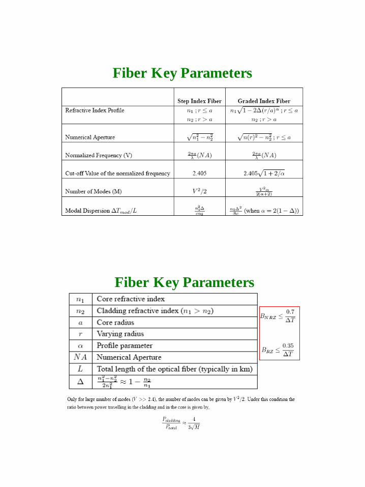
Fiber Key Parameters
Fiber Key Parameters

Major Issues in fiber-optic
Effects of Dispersion and Attenuation
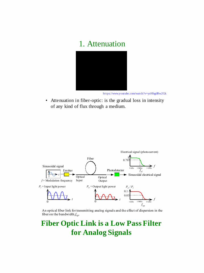
1. Attenuation
• Attenuation in fiber-optic: is the gradual loss in intensity
of any kind of flux through a medium.
https://www.youtube.com/watch?v=yzHhgdRw2Gk
t0
Pi = Input light power
Emitter
Optical
InputOptical
Output
Fiber
Photodetector
Sinusoidal signal
Sinusoidal electrical signalt
t0
f1 kHz 1 MHz 1 GHz
Po / Pi
fop
0.1
0.05
f = Modulation frequency
An optical fiber link for transmitting analog signals and the effect of dispersion in thefiber on the bandwidth, fop.
Po = Output light power
Electrical signal (photocurrent)
fel
10.707
f1 kHz 1 MHz 1 GHz
© 1999 S.O. Kasap, Optoelectronics (Prentice Hall)
Fiber Optic Link is a Low Pass Filter
for Analog Signals

Attenuation Vs Frequency
Attenuation in Fiber
Attenuation Coefficient
• Silica has lowest attenuation at 1550 nm
• Water molecules resonate and give high
attenuation around 1400 nm in standard fibers
• Attenuation happens because:
– Absorption (extrinsic and intrinsic)
– Scattering losses (Rayleigh, Raman and Brillouin…)
– Bending losses (macro and micro bending)
dB/km dB)(dB)0(
z
zPP

All Wave Fiber for DWDM
Lowest attenuation occurs at
1550 nm for Silica A
tten
uati
on
ch
ara
cte
rist
ics

Escaping wave
c
Microbending
R
Cladding
Core
Field distribution
Sharp bends change the local waveguide geometry that can lead to wavesescaping. The zigzagging ray suddenly finds itself with an incidenceangle that gives rise to either a transmitted wave, or to a greatercladding penetration; the field reaches the outside medium and some lightenergy is lost.
© 1999 S.O. Kasap, Optoelectronics (Prentice Hall)
Bending Loss
Power loss in a curved fiber
Power in the evanescent field evaporates first

Bending-induced attenuation
Micro-bending losses

2. Dispersion
• Dispersion is the phenomenon in which the phase velocity of a
wave depends on its frequency.
• Media having this common property may be termed dispersive
media.
• Sometimes the term chromatic dispersion is used for specificity.
https://www.youtube.com/watch?v=SAEQND4NyoM
Dispersion for Digital Signals
t0
Emitter
Very short
light pulses
Input Output
Fiber
Photodetector
Digital signal
Information Information
t0
~2²
T
t
Output IntensityInput Intensity
²
An optical fiber link for transmitting digital information and the effect ofdispersion in the fiber on the output pulses.
© 1999 S.O. Kasap, Optoelectronics (Prentice Hall)
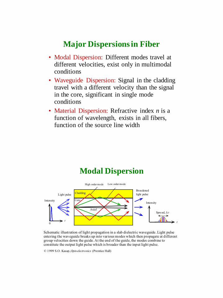
Major Dispersions in Fiber
• Modal Dispersion: Different modes travel at different velocities, exist only in multimodal conditions
• Waveguide Dispersion: Signal in the cladding travel with a different velocity than the signal in the core, significant in single mode conditions
• Material Dispersion: Refractive index n is a function of wavelength, exists in all fibers, function of the source line width
Low order modeHigh order mode
Cladding
Core
Light pulse
t0 t
Spread,
Broadened
light pulse
IntensityIntensity
Axial
Schematic illustration of light propagation in a slab dielectric waveguide. Light pulseentering the waveguide breaks up into various modes which then propagate at differentgroup velocities down the guide. At the end of the guide, the modes combine toconstitute the output light pulse which is broader than the input light pulse.
© 1999 S.O. Kasap, Optoelectronics (Prentice Hall)
Modal Dispersion

Polarization Mode Dispersion (PMD)
Each polarization state
has a different
velocity PMD
PM dispersion
• https://www.youtube.com/watch?v=DKCHYUxXYXo

t
Spread, ²
t0
Spectrum, ²
12o
Intensity Intensity Intensity
Cladding
CoreEmitter
Very short
light pulse
vg(
2)
vg(
1)
Input
Output
All excitation sources are inherently non-monochromatic and emit within aspectrum, ² , of wavelengths. Waves in the guide with different free spacewavelengths travel at different group velocities due to the wavelength dependenceof n1. The waves arrive at the end of the fiber at different times and hence result in
a broadened output pulse.
© 1999 S.O. Kasap, Optoelectronics (Prentice Hall)
Material Dispersion
Material Dispersion
Zero
Dispersion
Wavelength
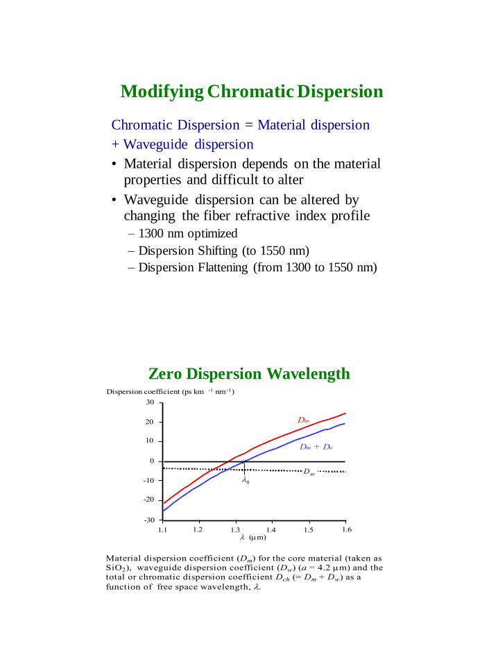
Modifying Chromatic Dispersion
Chromatic Dispersion = Material dispersion
+ Waveguide dispersion
• Material dispersion depends on the material properties and difficult to alter
• Waveguide dispersion can be altered by changing the fiber refractive index profile
– 1300 nm optimized
– Dispersion Shifting (to 1550 nm)
– Dispersion Flattening (from 1300 to 1550 nm)
Zero Dispersion Wavelength
0
1.2 1.3 1.4 1.5 1.61.1
-30
20
30
10
-20
-10
(m)
Dm
Dm + Dw
Dw0
Dispersion coefficient (ps km -1 nm -1)
Material dispersion coefficient (Dm) for the core material (taken asSiO2), waveguide dispersion coefficient (Dw) (a = 4.2 m) and the
total or chromatic dispersion coefficient Dch (= Dm + Dw) as a
function of free space wavelength,
© 1999 S.O. Kasap, Optoelectronics (Prentice Hall)
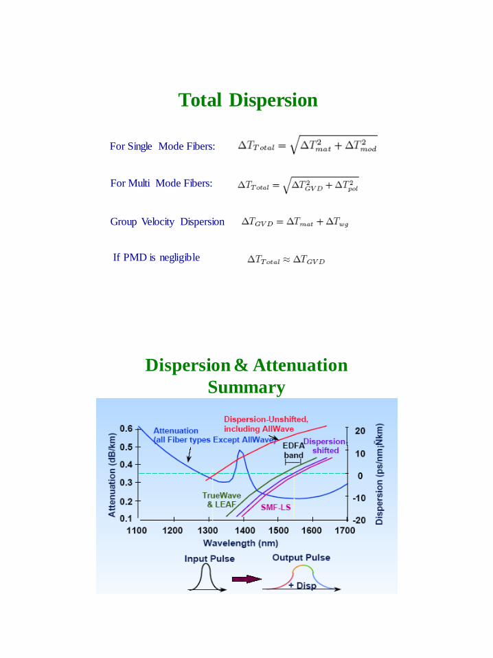
Total Dispersion
For Single Mode Fibers:
For Multi Mode Fibers:
Group Velocity Dispersion
If PMD is negligible
Dispersion & Attenuation
Summary

Fiber
Production, Installation, Maintains tools
• Left to group of students (25 minutes) next
time.
• Who?

![Excitation and Propagation of Guided Waves in Multilayer ... · propagation in hollow cylindrical structures. Li et al.[9] modeled the guided wave propagation in a pressure vessel](https://img.dokumen.tips/doc/110x75/60610ee6bd7e2a0a42396346/excitation-and-propagation-of-guided-waves-in-multilayer-propagation-in-hollow.jpg)


![6.0 Optical Propagation and Communication - [email protected]](https://img.dokumen.tips/doc/110x75/62073f9049d709492c2f791a/60-optical-propagation-and-communication-emailprotected.jpg)


