Embed Size (px)
Citation preview

SSERC Guide to practical physics 1
Guide to practical
physics

SSERC Guide to practical physics 2
Contents
Who is this guide for? 3
Basic health and safety in physics 4
Light gates and timers 9
Ray boxes 15
Alpha electronics kit 21
Meters 26
Oscilloscopes 33
Power supplies 36
Signal generators 39
The gas laws 43
Working with lasers 51
UV (including the photoelectric effect) 56
Circuits revisited 64
Working with high tension and extra high tension 67
Teltron tubes 70
EHT and discharge tubes 80
Detecting radiation 81
Vacuum pumps and bell jars 92

SSERC Guide to practical physics 3
Who is this guide for?
This guide is for teachers of physics and for technicians. It is derived from the course notes given out at our Introductory and Intermediate Physics for Technicians courses. We have produced it following suggestions that teachers, particularly new teachers and those whose specialism isn’t physics, would find it useful too. Some parts will suit teachers who are teaching physics components of BGE courses but who don’t have a formal physics qualification. Such teachers are unlikely to be interested in the sections on working with high tension supplies. Other parts will suit physics teachers with senior phase classes. Teachers with a formal physics qualification are likely to find some material, for example the section on using a multimeter, fairly trivial. We have retained the “For interest” explanations. These too are unlikely to be needed by physics teachers. Whilst every Pyrex test tube is pretty much the same as every other Pyrex test tube save for size, there are a bewildering variety of meters, timers and so forth in use in physics teaching. We can’t cover everything, but we have a large store of equipment and an archive of equipment manuals. Please get in touch to see if we can help. The guide gives basic set up information, safety advice and hints and tips. It is intended to be an ever-evolving document, so please do feed back with your comments and suggestions for new sections. [email protected] [email protected]

SSERC Guide to practical physics 4
Section 1: Basic Health and Safety in Physics
Introduction As with any activity, those involving physics apparatus must be risk assessed. Generic risk assessments may be used but it is vital that these are checked to ensure that they are suitable for the particular equipment and set of circumstances you find yourself dealing with. If they are not suitable, they must be amended. Risk assessment is covered in SSERC safety courses and we can always help by email etc. A blank risk assessment template and generic risk assessments can be found on the SSERC website: www.sserc.org.uk. Many of the topics below are covered in greater depth in the relevant section of this document. Electrical Safety - Portable Appliance Testing (PAT) Portable electrical appliances must be inspected and tested regularly to ensure that they are properly maintained so as to prevent danger. The prime responsibility for this lies with employers and it is their duty to set up a routine inspection and maintenance programme as a recognised means of ensuring that appliances remain in a safe condition. In this context it is assumed that a portable appliance is:
• any appliance fitted with a plug top;
• any appliance capable of being readily disconnected from and reconnected to an electrical system;
• any appliance that requires a supply voltage in excess of 33 V ac rms or 70 V dc ripple free.
A sticker that claims that a piece of electrical equipment has been PAT tested only tells you that the equipment was satisfactory on the day of the test. It is rather like the MoT test for a car. An MoT certificate issued in June does not tell you much about the state of the tyres or brake pads in December. Whilst you should check that any portable electrical appliance you are issuing has indeed been tested, you should also conduct a quick visual test before, during and after use as follows:
• Check the supply cable throughout its length for signs of deterioration or damage;
• Check that the casing of the appliance is free from cracks;
• Check that the plug is free from cracks and that the outer insulation of the cable is firmly gripped by the cable clamps at both the plug and the appliance ends.

SSERC Guide to practical physics 5
Power Supplies
The classification of power supplies used in education is shown below.
Power supply type Voltage output
Current output Hazard
LT (Low Tension) Usually no more than 25 V*
<9 A
Generally no risk of electric shock except in applications with inductors. Risk of burns or fire
HT (High Tension) Generally 400 V maximum
Unlimited. Maximum values typically lie between 80 mA and 400 mA
Hazardous live Risk of electrocution
EHT (Extra High Tension)
5 kV 5 mA absolute limit Typical maxima are 2 mA or 3 mA
Either outwith, or just inside, the hazardous live regime. Risk of harm is unlikely
Table taken from SSERC Bulletin 208 Power supplies are classified by their electrical outputs and the hazards presented *For more information, please see the notes on Power Supplies
The only power supply type that clearly presents a risk of electrocution is the HT power supply. These have a limited application in physics and are used chiefly with certain Teltron tubes and for neon lamp excitation. Transformer Experiments
Some activities in S4 and S5 physics involve pupils constructing transformers which can be used to step-up low voltages to higher ones. This usually involves using pairs of pre-wound transformer coils and harm can be avoided by following these rules:
• Use an ac power supply that is either designed or locked to give no more than 2 V;
• Give out coils such that it is impossible for pupils to use a pair of coils where one set has more than 12 times as many turns as the other. In other words, if the smallest coil has 60 turns, it’s OK for your largest coil to have 500 turns, but not 5000 turns. This guidance ensures that the output of your transformer is not a hazardous live.

SSERC Guide to practical physics 6
Van De Graaff Generators Although these devices seem to break the rules in that they can charge up to more than 100,000 V, we allow pupils to hold on to them and inevitably some receive shocks. It is a myth that charging pupils up using a Van De Graaff Generator is now banned, but the safety rules shown below should be followed. If your department is considering buying a new machine, consult the SSERC website (or a SSERC physicist) first to make sure the one you buy conforms to our current guidelines. The following rules should be applied:
• Before using a Van De Graaff generator teachers should check the appropriate school records for any relevant heart condition and should warn the class that it should not be used by anyone with such a heart condition;
• The dome should be discharged immediately after every operation ensuring that it never stands idle in a charged condition;
• The dome can be safely discharged by touching it with an earthed, metal conductor. The usual means is by a spark discharge to an earthed metal sphere mounted on a stand, or hand-held with a handle, which need not be insulated. If this is earthed, the operator does not receive a shock;
• The dome can also be safely discharged by touching it with a pointed metal wand which is earthed. The resulting corona discharge is accompanied by little or no sparking;
• The dome may be safely discharged through the human body by a corona discharge. With one hand firmly on the workbench, rapidly bring up an outstretched finger of the other hand to touch the charged dome. The shock is mild and not unpleasant. This is a safe way to discharge the dome. In contrast, were you to bring up a raised fist to the dome, the machine discharges all its energy in one burst as a hurtful spark.
• The demonstration with hair standing on end may be done safely by adapting the above procedure. Begin with the generator off and dome uncharged. The pupil should stand on an insulated platform (such as a plastic basin), placing one hand on the dome while ensuring that no part of the body or clothing is in contact with the bench, or another person. Start the generator and run until hairs stand on end. Stop the generator and instruct the pupil to place his or her free hand on the benchtop while still keeping the other hand firmly on the dome. Wait several seconds until completely discharged. Then tell the pupil to remove the hand from dome,

SSERC Guide to practical physics 7
step off the platform and walk away from the apparatus. The dome at this stage will not be carrying a charge and will be safe for another person to touch;
• Persons being charged should be limited to volunteers;
• Pupils can be charged in a chain. The number needn’t be limited unless standing on insulated platforms, in which case no more than three;
• The demonstration of lighting a Bunsen flame by discharging through a human body via a pointed fingertip to the Bunsen funnel would seem also to be fairly harmless. Being a corona discharge, the spark energy is low;
• Because a human body has capacitance, do not let someone who has been in contact with a charged dome walk away without discharging. In these circumstances such a person may carry quite a lot of charge and experience a disagreeable and possibly unexpected electric shock on touching earth. Any other person touching such a charged person is also at risk of receiving a shock;
• If the capacitance of the system were to be greatly increased, for instance by connecting the dome to a Leyden jar, the stored electric energy can increase dangerously. If it really is necessary to work with a Leyden jar then the person working with the apparatus must be a teacher who is competent to do the demonstration;
• Do bear in mind that any person getting a shock is at risk of harm from jerking or falling over in fright. There is then an indirect risk of a blow to the head, or damage to muscles, bones, or other parts;
• During spark discharges, electromagnetic energy is radiated from the spark gap. This radiated energy will be picked up by any nearby electrical leads across which extra-high voltages can be induced. These voltages can destroy electronic apparatus. Vulnerable equipment includes anything supplied from a plug-top power supply such as a laptop computer, digital balance or digital camera because the long supply lead can act as an effective pick-up aerial. No such equipment should be within 2 m of a spark gap;
• All science staff should be trained in how to work with the Van de Graaff generator and should be instructed to avoid a direct path through the human body to a good earth.
• As we are unable to obtain information on medical implants such as pacemakers and cochlear implants, we advise that not only do you not charge people with implants, they should also stand 6 m or more from an operating Van de Graaff generator. This only applies to implants with electrical or electronic parts, though pupils with artificial joints or limbs may be at risk of falling when charged.

SSERC Guide to practical physics 8
Lasers Lasers are good light sources for use in schools. They produce beams that are bright enough to be seen even when the classroom lights are on. Pupils in S1 to S6 can use lasers, provided that safety guidelines are followed. These are described in the section on Lasers. Mercury Mercury is used in the Charles’ Law experiment in N5 physics where a small thread is used to trap air in a capillary tube. These tubes are immersed in very hot water and some teachers and technicians worry about mercury vapour being released as a result. However, SSERC has investigated this and has been unable to detect any vaporisation of mercury from this activity. There is more detail in the Gas Laws section. Soldering Soldering is only carried out on rare occasions in some schools whilst in others it is fairly routine. The following practices should be adopted:
• Use rosin-free solder;
• Ensure that windows and doors are open to ventilate the workplace;
• Install LEV (local exhaust ventilation) if a lot of soldering is done. This is a legal requirement if rosin-based solders are used;
• Clean worktop surfaces, at least, at the end of each lesson by:
(1) sweeping debris into a dustpan, and (2) wiping clean with a damp disposable towel. Hands should then be washed and clothes brushed.
• SSERC recommends using low voltage (e.g. 24 V) soldering irons with stands.
Working With Radioactive Sources This guide contains advice on setting up certain experiments on natural radioactivity. If you wish to use sealed sources, please see the appropriate section of the Physics Health and Safety area of the SSERC website.

SSERC Guide to practical physics 9
Section 2: Light Gates and Timers Electronic Timers Physics pupils are often asked to calculate speed by measuring a distance and finding the time to cover that distance. Speed is found by dividing distance by time. Stopwatches are fine for times of around five seconds or more, but because of human reaction time they are no use for short times. In such cases, we use timers that can be started and stopped electronically.
Figure 1: Electronic timer
Light Gates The most common way of starting and stopping a timer is to use a light gate.
Figure 2: Light gate
On the right is a light source, pointing at a light detector. The source is connected to a power supply (timers such as the one shown in Figure 1 have a built-in power supply for light sources - note the 2 V 0.5 A sockets). The detector is connected to the START or STOP sockets. Picture a beam of light going from the source to the detector. Breaking the beam starts or stops the timer. The beauty of this arrangement is that there is no human reaction time to affect the measurement of time. Also, the object whose time you are measuring is not slowed down when passing through the beam. If you are measuring the speed of a trolley, model car or similar, it has to be fitted with a “mask” to cut the light beam.

SSERC Guide to practical physics 10
Timing Using Light Gates Average Speed
Figure 3: Trolley with a mask.
The light gates shown in Figure 2 are mounted on a clamp stand with the source on one side of a trolley ramp and the detector on the other. They can be difficult to line up and some manufacturers make light gates with the source and detector in a single unit. One such device is shown in Figure 4 below:
Figure 4: Combined light source and detector. The photodiode is the light detector.

SSERC Guide to practical physics 11
The following diagram shows a typical set-up to measure the average speed of a trolley going down a slope:
Figure 5: Measuring average speed using two light gates
The teacher or pupils will measure the distance between the light gates. It makes sense to put them a memorable distance apart, e.g. 50 cm, 100 cm, measuring from the same point on each gate.
• Connect light gate 1 to the start sockets of the timer;
• Connect light gate 2 to the stop sockets.
Each light gate’s light source needs to be connected to a suitable power supply unless the light gate is battery operated. Some timers, as mentioned previously, have sockets for light sources.
• Pass your hand through light gate 1. The timer should start. It should stop when you pass your hand through light gate 2.
If this doesn’t happen, or if the timer runs without stopping as soon as you connect things, try the following:
• Are the lights in the sources on?
• Are they bright? If not, you may be using the wrong power supply voltage
• Have you accidentally connected the detectors to the power supply instead of the sources?
• Try swapping the detector leads around (black where red was, for example)
• Switch the timer off
• Switch it back on and try again
• If the timer has a mode switch (usually “mode 1/2"), try a different setting
Trolley and mask Light gate 1
Light gate 2
Timer

SSERC Guide to practical physics 12
• Substitute a different light gate.
• For the light gate unit shown in Figure 4, the fledgling supervillain can cause havoc by removing the small, black collar screwed into the ring on the detector part of the light gate. This is almost impossible to spot unless you know to look for it, but it lets too much light into the detector and make it very difficult to start or stop the timer.
Once the timer starts and stops properly, check that the trolley runs freely down the slope and that the mask cuts both beams without hitting against any of the equipment.
Reset the timer to zero. Instantaneous Speed The previous experiment showed how to measure the average speed of a trolley as it ran down a ramp. However, if we want to measure the speed at a particular point (the instantaneous speed) the last experiment would be of no use because the speed of the trolley would be changing all the time - slow at the first light gate, faster at the second. To get the instantaneous speed, the average speed over a short distance has to be measured since the speed does not have much chance to change over a short distance. It could be possible to do this by putting the light gates closer together; but there is a much better way. (See figure 6 below) It involves using one light gate only and a mask of known width. The timer is set to start when the beam is broken and stop when it is restored, i.e. when the mask comes out of the light gate. The speed is calculated by dividing the length of the card by the time on the timer. If setting this up, make the mask length something like 4 cm or 5 cm rather than 3.4567 cm. How you set the timer up depends on the model of timer.

SSERC Guide to practical physics 13
Figure 6: Measuring instantaneous speed using a single light gate
To check this set-up, put your hand in the beam. The timer should run for as long as the beam is blocked out.
Timers with Built-in Microprocessors Figure 7 (below) shows two devices used in many schools- the Unilab QED (background) and the DJB TSA (foreground). They are timers with built-in processors. They can record more than one time and, if you enter the width of the mask into them, can calculate speed and acceleration.
Figure 7: Timers with built-in microprocessors
Trolley and mask Light gate
Timer
Known width

SSERC Guide to practical physics 14
Trolley with Double Mask If using timers like those shown in figure 7 and a single light gate to find acceleration, you will need to fit your trolley with a double mask (figure 8). This is because acceleration is found from 2 speeds and the time it takes to get from one speed to another. Each of the two parts of the mask has to be the same width but the width of the gap is not important.
Figure 8: Trolley with a double mask.

SSERC Guide to practical physics 15
Section 3: Ray Boxes Lenses, Prisms and Mirrors Ray boxes are frequently used with mirrors, glass or Perspex shapes. The pictures shown in Figure 9 below are often used in student notes and work cards to represent these shapes, as seen from above.
Figure 9: Representations of optical components
The shapes shown above are two dimensional representations of the apparatus shown on the left.
Figure 10: Optical components
Triangular prism
Semi-circular prism
Mirror (concave and convex
mirrors are sometimes used)
too)
Convex or converging lens
Concave or Diverging Lens ('Caves' curve in the way!)

SSERC Guide to practical physics 16
Using a Ray Box Most ray boxes contain a 12 V filament bulb rated at around 24 W. However, laser and LED light sources are beginning to find their way into schools but for the purposes of this course we will deal chiefly with the filament bulb variety. These are connected to a 12 V supply and it is usual, though not essential, to use ac. Safety warning! The metal parts of a ray box can become quite hot if it is switched on for any significant length of time.
The light coming from the box on the left is not suitable for carrying out experiments. We usually want either one or more rays and often we want the rays to be parallel, not diverging as the light is in Figure 11.
Figure 11
To make a parallel beam of light, we use a cylindrical lens similar to that shown in Figure 12. The ray box shown below has a number of grooves into which the lens can be placed. Find the place where the lens makes the beam parallel as shown in Figure 13.
Figure 12
Some ray boxes there may only be one fixed slot for the cylindrical lens but to obtain a parallel beam the position of the lamp is changed using a slider control. Now put the slits in place. Different configurations are shown in Figure 14.
Figure 13

SSERC Guide to practical physics 17
Figure 14
If diverging rays are required, leave out the cylindrical lens (rightmost image).

SSERC Guide to practical physics 18
Common Ray Box Applications The pictures below show common ray box applications. To make the photographs clearer, a laser ray box was used in most cases.
Here a convex lens is bringing rays of light to a point of focus. If the lens was more curved (often described in physics text books as “fatter”), the point of focus would be closer to the lens. If the ray box was set to give diverging rays, the point of focus would be further away.
This is a concave or diverging lens. Parallel rays from the ray box are made to spread out by the lens. What we are seeing in all these cases where light changes direction when going from one substance to another is a phenomenon called refraction.
Here a single ray enters a rectangular block. It emerges parallel to the direction it entered at. Note that some of the light is reflected at the surface of the block. This always happens when light goes from one substance to another, unless it enters “head on” at 90 degrees to the surface.
The experiment on the left is one of the most important, not to say beautiful ones, in physics. Here we are using a Perspex prism. More expensive glass prisms will give better spectra as will more sophisticated set-ups. See SSERC Bulletin 220 for details on how to produce the ultimate spectrum.
Red light is passed through a triangular prism. Try to follow the ray, ignoring reflections.
White light follows the same path as the red light but it splits up into different colours, forming a visible spectrum. White light is a mixture of all colours but red light is a single colour so it does not split.
A single ray reflects from a plane (flat) mirror. It leaves the mirror at the same angle it struck it.
This concave mirror brings rays to a point of focus. Satellite dishes work in this way, concentrating weak signals from space on a single point.
Inside the glass block, a special kind of reflection called Total Internal Reflection is taking place. The ray is striking the mid point of the semi-circular prism’s flat face.

SSERC Guide to practical physics 19
Colour Mixing Some companies now market colour mixers that use LEDs and SSERC also has a number of different designs that can be assembled in school. Colour mixing can also be performed using ray boxes and filters. The best results will be obtained using three ray boxes, one with a red, one with a blue and the third with a green filter in the slots where the slits usually go. Shine the ray boxes on to a white surface and make the colours overlap. What you will see may surprise you if your experience of colour mixing has been limited to mixing paints. The kind of colour mixing that happens with ray boxes is called additive colour mixing.
Here is what you should see:
Red + Blue = Magenta (purplish colour)
Blue + Green = Cyan (turquoise)
Red + Green = Yellow
Red + Blue + Green = White Figure 15
It can be difficult to get a pure white. Should this be the case, try altering the brightness of the individual colours - if each ray box has its own variable power supply. Some ray boxes are designed to be able to colour mix using a single ray box. Some require additional mirrors to do this, while others have the mirrors built in.
In the picture (left) we see a ray box with a red filter in the front slots, a green filter on its right and a blue filter on its left. A mirror has been used to reflect the green light so that it overlaps with the red light, forming the colour yellow.
Figure 16

SSERC Guide to practical physics 20
LED (Light Emitting Diode) Sources SSERC Bulletins 212 and 220 give details on how to use bright white LEDs for school optics experiments. These can be effective replacements for ray boxes. Lasers Many schools have a laser that is used by teachers for demonstrations. A number of companies now make laser ray boxes. Section 10 of this guide looks at lasers in detail.

SSERC Guide to practical physics 21
Section 4: Alpha Electronics Kit Alpha kit, which is used in schools to teach electronics, consists of boards and components that are built up to make circuits. The boards fit together using yellow links with screw fittings that are hand-tightened. Power Supplies for Alpha Boards Figure 17 (below) shows a battery being used to power the boards, but other methods are possible and will be dealt with below. Refer to Section 7: Power Supplies for explanations of terms such as “smoothed” and “regulated”.
Figure 17: Board powered by a battery
Regulated/Smoothed Power Supply The power supply shown below (Figure 18) gives an unregulated, unsmoothed output. On its own this is unsuitable for use with Alpha kit and the board shown (Figure 19) is used to smooth and regulate its output.
Figure 18: Power Supply Figure 19: Regulator Board

SSERC Guide to practical physics 22
The leftmost sockets on the power supply shown (Figure 20) provide a suitable output for Alpha kit but most schools use battery connector boards and 6V batteries, as shown in Figure 21.
Figure 20: Suitable power supply Figure 21: Battery connector
board with 6V battery
Joining Boards To join boards together, slacken the screws on the yellow link shown in Figure 22. Note: Links have a raised bit on them which matches a notch on the boards and care should be taken to ensure that the link is fitted the correct way round, with the raised bit in the notch. It is possible to join boards with the links connected the wrong way, but the circuit will not work. When both boards are in place, tighten all three screws. The screws are not simply holding the boards together - they are also making electrical connections.
Figure 22: Link Figure 23: Board showing notch Figure 24: Board with link

SSERC Guide to practical physics 23
Fault Finding There will be occasions when you set up a circuit and it doesn't appear to work. The first thing to consider is, “Is it actually not working?” Some circuits will only do something if it gets dark, cold or damp. For example, the circuit shown in Figure 17 would only light the bulb if it got dark. It therefore helps to know what a circuit is supposed to do before you build it. Variable Resistor Some circuits contain a variable resistor like the one in the picture to the left. This may need to be adjusted for the circuit to work properly. For example, suppose that the light in the circuit shown in Figure 17 comes on all the time. The variable resistor should be adjusted until the light goes off when the room is bright. The light should then come on when the light detector is covered.
Figure 25: Variable resistor
Thermistor A thermistor is a temperature-sensitive component that is used in circuits where a buzzer, light or motor has to be switched on when it gets hot. Warm the thermistor by holding it between your finger and thumb, not by heating it with a Bunsen! Connections Most other faults are caused by slack links or by poorly connected batteries. All connections should be checked for tightness. In many cases, a circuit will work if the blue battery connector is removed and refitted.

SSERC Guide to practical physics 24
Microchips
Faulty boards which have microchips fitted should be checked to ensure that the connecting pins of the microchip haven't been damaged while being fitted. It's not uncommon for pupils to remove microchips (more out of curiosity than badness) and then damage the pins when trying to put them back in.
Figure 26: Board with microchip
Poorly Fitted Components The board shown below (Figure 27) has sockets cut out to allow components to be plugged in. These components do not always fit well and if a fault occurs when the circuit is built, the components should be moved gently from side to side to see if the circuit works temporarily.
Figure 27: Board with component socket
Replacing Components Substituting components or complete boards is a good fault finding technique. Start with the battery, then the blue battery connector, working your way through the circuit. The best way to check is to swap components one at a time from a circuit that is known to be working.

SSERC Guide to practical physics 25
Fault Finding Using a Voltmeter A voltmeter (see next section) can be used as an aid to fault diagnosis. Start with it connected across the first yellow link in the circuit, as shown on the left. It should read just over 6 V and this should not drop much below 6 V when the circuit is operated. If it does, check the battery. It may require to be replaced with a fresh one. Voltage should also remain fairly constant as you move from one link to another. There are more sophisticated fault finding techniques you can do using a voltmeter. Connect the meter between the lower (zero line) socket of the link before the transistor board or transducer driver board. Now connect the other socket of the voltmeter to the centre socket on the link. A transistor will switch on the output device (LED, buzzer) when this voltage rises above around 0.7 V. Around 2.1 V is required to switch the transducer driver. If your battery is OK and all your connections are good but you still can’t get these voltages, try a different value of variable resistor. Note that the Transducer Driver board is required if your output device is a motor or filament bulb. The Transistor board doesn’t work with these components as they require a larger current than it can handle.
Figure 28: Fault finding using a meter

SSERC Guide to practical physics 26
Section 5: Meters Multimeter The meter shown below (Figure 29) is known as a multimeter. This is because it can be set to measure a number of different electrical quantities.
Current Current is measured in Amperes (Amps or A for short) and is a measure of the flow of electric charge in a circuit. Voltage Sometimes referred to as potential difference or pd, voltage is a measure of the electrical pressure or “push” on charges. It is measured in volts (V). Resistance Resistance is a measure of how hard it is to make charges flow through substances. Electrical conductors have low resistances and insulators have high ones. Resistance is measured in ohms (Ω).
Figure 29: Multimeter
Most meters can be set to work with alternating current (ac) and direct current (dc). See Section 7: Power Supplies for the difference between ac and dc. kilo, Mega, milli, micro
Kilo (k) = 1000 (1 kΩ is 1000 Ω); Mega (M) = 1,000,000 (3 MΩ is 3 000 000 Ω); milli (m) = 1/1000 (200 mA is 200/1000 A or 0.2 A);
micro () = 1/1,000,000 (30 A is 30/1,000,000 A or 0.00003 A).

SSERC Guide to practical physics 27
Measuring Current Using a Meter
Figure 30: Typical circuit with circuit diagram (right)
To measure the current in the circuit in Figure 30, there are 3 things that have to be done: 1 select the correct meter settings; 2 use the correct sockets; 3 connect the meter in the correct position in the circuit.
Figure 31: Switch with Figure 32: Selector dial (set Figure 33: One lead in the COM (common) socket DC selected to 10 A) with the other in the 10 A socket
Since the circuit is battery powered the current to be measured will be dc. The dc setting should be selected using the slide switch as shown (figure 31). The meter shown has a slide switch to select dc or ac measurements but some meters have separate settings on the selector dial for ac and dc The dial is set to 10 A (Figure 32) which is the greatest current that the meter can measure. If you are unsure of what range the current is likely to be in, it makes sense to start at the largest setting. No matter what we are measuring, we will always have one lead in the COM (common) socket. In this case, the other lead goes in the 10 A socket (figure 33).

SSERC Guide to practical physics 28
Figure 34: Circuit with meter connected for measuring current / circuit diagram (right)
As current is a flow of charge we have to let the charge flow through the ammeter in order to measure it. To do this we have to break the circuit and put the ammeter in the gap, using an extra lead to complete the circuit again. This is described as “connecting in series”. Notes
• If the reading on the meter is negative, you can make it read positive by swapping the leads around (i.e. put the lead that was in COM into 10 A and vice versa).
• If the reading on the meter is zero, or very small, try a more sensitive setting on the selector, e.g. 200 mA but you will have to use the mA socket instead of the 10 A one. Disconnect the meter when changing settings.
• If a '1' appears on the left hand side of the meter display, the reading is off the scale and you will have to select a less sensitive setting. This will not happen with the 10 A setting used with the circuit above.
• Some meters autorange; set the selector to 'A' and the best range will be selected automatically for you.
• Meters usually have a protective internal fuse. A sure sign that the fuse is blown is that the meter appears fine – the display can be seen, but the low current setting does not work. A tip on how to use one meter to test the fuse on another will be given later.
A

SSERC Guide to practical physics 29
5.3 Measuring Voltage Using a Meter If we want to measure the voltage (potential difference) across the left hand bulb in the above circuit we will once again have to consider the settings, sockets and meter position. We also need to consider whether we are measuring ac or dc.
Figure 35: Selector dial set to 20V Figure 36: Leads connected to COM and V sockets
The 20 V setting is a good bet for most classroom work. It is very unlikely that you would use a higher setting. Pupils are not allowed to work with voltages over 33 V ac or 70 V ripple-free dc (see Section 7: 'Power Supplies' for an explanation of “ripple-free”). The 'V' and 'COM' sockets are always used when measuring voltage.
Figure 37: Circuit with meter connected for measuring voltage / circuit diagram (right) In this case we are measuring the voltage across a component. This gives us a clue as to how the voltmeter is connected. The circuit is not broken to connect the meter. Instead, the meter is connected across the bulb using stackable leads. This is described as “connecting in parallel”.
V

SSERC Guide to practical physics 30
Fault Finding Using a Meter Checking the Power Supply Suppose you have a circuit like the one above but connected to a power supply rather than batteries. You are sure that you have wired it correctly and that the bulbs have the correct ratings but they do not light. How can you find the fault? Firstly, you could check the output from your power supply. Don't assume that because the light is on in your power supply that it is actually working.
• Set your meter to 20 V;
• select ac or dc (this will depend on whether you are using the yellow or black and red sockets);
• connect 'V' and 'COM' to your power supply.
If the power supply is working, the meter should give a reading. The reading may not be exactly the same as your power supply selector dial claims but an explanation for this can be found in Section 7: Power Supplies. Warning! Under no circumstances should you attempt to measure mains voltages, HT or EHT voltages with this meter. Meters for measuring such voltages should be two-socket, high impedance meters with probes to the standard outlined in HSE Guidance Note GS 38. Fault Finding Using the Resistance Setting
Figure 38: Selector dial set for Figure 39: Connections used for measuring resistance measuring resistance
The pictures above (figures 38 / 39) show the settings and sockets for using a multimeter to measure resistance. Used like this, the meter is very useful for identifying faulty components such as wires, switches and bulbs.

SSERC Guide to practical physics 31
Warning! When testing wires, bulbs, etc with a resistance meter, they must be removed from the circuit. Also, do not test batteries with a meter that has been set to measure resistance. Use the voltage setting instead. It is not unsafe to do so, it just does not work.
a) Testing Connecting Wires Connecting wires should have a low resistance (eg 0.1 Ω or so) as shown in Figure 40.
Figure 40: Meter display showing typical reading
When testing a wire, it should be connected from the 'COM' socket to the 'Ω' socket. If you get a reading like the one shown below (Figure 41), the wire is faulty (usually a break somewhere along its length or a poor connection between the wire and socket).
This fault is known as an 'open circuit'.
Figure 41: Meter displaying an 'Open Circuit' fault

SSERC Guide to practical physics 32
b) Testing Bulbs Bulbs can also be tested using a meter and should have a resistance of a few ohms (as shown in figure 42). If you get an open circuit reading, like the one above, either the bulb (or its holder) is faulty. In such cases the bulb should be checked to ensure that it is properly screwed in!
Figure 42: Testing a bulb using a meter
Occasionally, a bulb will fail to light and have a much lower resistance than it should (about the same as the resistance of a wire).
This fault is known as a 'short circuit'. c) Testing Switches Switches should have a very low resistance when they are switched on and an open circuit resistance when they are off. d) Testing the internal fuse of a meter You can remove the fuse from a meter and test it the same way that you would test a wire. Alternatively, you can test one meter using another.
• Set the meter that you suspect to be faulty to a low current setting (eg 200 mA).
• Set the meter you are using as a test instrument to 200 ohms.
• Connect COM to COM.
• Connect the V/ohm socket on the test meter to the low current socket on the suspect meter.
• If the fuse has blown, there will be an open circuit reading on the test meter.

SSERC Guide to practical physics 33
Section 6: Oscilloscopes
Oscilloscopes are used for examining electrical signals. In schools, they are often connected to signal generators, microphones and power supplies, usually to show pupils the difference between ac and dc. Some schools are now using LCD or USB oscilloscopes. The instructions below are for older Cathode Ray Oscilloscopes (CROs). LCD and USB oscilloscopes often have an automatic mode that chooses settings for you but a knowledge of what the controls on a CRO do can still be helpful.
Figure 43: Typical oscilloscope
Getting a Trace The following instructions assume that you are going to connect a working signal generator to the oscilloscope (signal generators are covered in Section 8).
• Don’t connect anything to the oscilloscope initially;
• Plug in the oscilloscope;
• Switch the oscilloscope on (note that on some models, the switch is on the back);
• Wait. Like old television sets, some oscilloscopes need time to “warm-up”. Before connecting anything to the oscilloscope, you should try to get a horizontal line across the middle of the screen. The line that appears on the screen is referred to as the trace.

SSERC Guide to practical physics 34
If you switch on your oscilloscope and don’t see either a line on the screen or a dot moving across it, try the following in the order shown:
• Locate the control marked trig level and turn it to auto;
• Turn up the brightness control;
• Adjust the x pos or x shift controls and the y pos or y shift controls. The trace may actually be lying off the screen and these controls move it left and right (x) or up and down (y) to bring it into view;
• If the trace appears as a splodge rather than a sharp dot or line, adjust the focus control and turn down the brightness.
The signal generator can now be connected to the Y input socket and switched on. It should be noted that, while many oscilloscopes have BNC sockets, some have 4 mm sockets.
The illustrations on the next page show the desired wave pattern that should be seen on the screen and the adjustments that have to be made in order to achieve this.

SSERC Guide to practical physics 35
Just right Adjust y pos or y shift
Adjust x pos or x shift Adjust y gain anti-clockwise (y gain may also be called y amplifier or sometimes just marked volts/div, v/div, v/cm etc)
Adjust y gain clockwise (y gain may also be called y amplifier or sometimes just marked volts/div, v/div, v/cm etc)
Adjust timebase anti-clockwise (timebase may simply be marked time/div or time/cm or ms/cm etc)
Adjust timebase clockwise (timebase may simply be marked time/div or time/cm or ms/cm etc)
An ideal trace is stationary. If it drifts or looks like this, look for a stability control or a variable timebase control.
SSERC Guide to practical physics 36
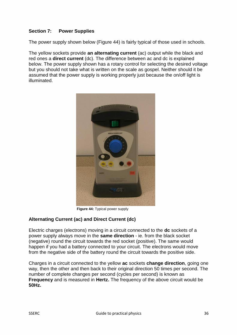
Section 7: Power Supplies The power supply shown below (Figure 44) is fairly typical of those used in schools. The yellow sockets provide an alternating current (ac) output while the black and red ones a direct current (dc). The difference between ac and dc is explained below. The power supply shown has a rotary control for selecting the desired voltage but you should not take what is written on the scale as gospel. Neither should it be assumed that the power supply is working properly just because the on/off light is illuminated.
Figure 44: Typical power supply Alternating Current (ac) and Direct Current (dc) Electric charges (electrons) moving in a circuit connected to the dc sockets of a power supply always move in the same direction - ie. from the black socket (negative) round the circuit towards the red socket (positive). The same would happen if you had a battery connected to your circuit. The electrons would move from the negative side of the battery round the circuit towards the positive side. Charges in a circuit connected to the yellow ac sockets change direction, going one way, then the other and then back to their original direction 50 times per second. The number of complete changes per second (cycles per second) is known as Frequency and is measured in Hertz. The frequency of the above circuit would be 50Hz.

SSERC Guide to practical physics 37
Rectification The UK mains supply is rated at 230 V ac. A power supply has to make this voltage into one that is safe for pupil use. If a dc output is required, the power supply must also be able to turn ac into dc. This is called Rectification and is illustrated in the oscilloscope traces below.
This is ac. The trace switches between being above and below the centre line. This shows that the electric charges change direction regularly.
This is dc which has been produced by rectifying an ac supply. It has not been "smoothed" as can be seen by the large “ripple”.
This is also dc. A trace like this would be produced using a battery or by smoothing a rectified ac supply. This is known as being "ripple-free".
As stated previously, most power supplies take the mains voltage of 230 V ac and bring it down (using a transformer) to a safe level for use in experiments. Voltage Loss Most school power supplies turn ac into dc using components called rectifiers or diodes and this will lead to a loss of voltage. If you set your power supply to, say, 6 V, you may well get an output of 6 V from the ac sockets but only around 4 V from the dc sockets. Some power supplies have two scales on their selectors, one for ac and one for dc. Others have information on their casings about the voltage difference between the two sets of sockets.

SSERC Guide to practical physics 38
Regulated Power Supplies In many power supplies (and all batteries), drawing current causes a small voltage drop. The larger the current drawn, the greater the drop in voltage (due to something called “internal resistance”). This does not happen with a regulated power supply (Figure 45). Its output remains steady.
Figure 45: Regulated power supply
This power supply is also smoothed. These features make it suitable for use with electronic circuits. The sockets on the right provide a dual rail output. This is used for circuits known as operational amplifiers (op amps). Protection School power supplies are often protected against misuse. Figure 46 shows the reset button on a Unilab power supply. It 'pops out' if too much current is drawn.
Should this happen, switch off, disconnect the circuit, check the circuit to see what was overloading the power supply, wait for a minute and push it back in again. The same power supply also has a mains fuse (Figure 47). School power supplies should require some sort of tool to remove the mains fuse.
Figure 46: Power supply with Figure 47: Mains fuse Reset button

SSERC Guide to practical physics 39
Section 8: Signal Generators Types and Common Uses Signal generators are mostly used in schools connected to loudspeakers to produce a variety of sounds. They may also be used with oscilloscopes to look at the electrical signals associated with sounds. As can be seen from the picture below (Figure 48), there are a number of different kinds of signal generator in use in schools.
Figure 48: Selection of signal generators
Common Controls Although there are many kinds of signal generators, they all have certain controls in common. The main ones are shown in Figure 49.
Waveform or Function Frequency Range Amplitude or Output
Figure 49: Signal generator controls

SSERC Guide to practical physics 40
Attenuator Control In addition, signal generators may have an Attenuator Control. Leave this set to '0'
(or '1' or '1' depending on the model being used).
Figure 50: Attenuator Controls
Connecting a Loudspeaker
• Turn the waveform control to: ~
• Turn the range control to: x100 Hz (not kHz)
• Turn the frequency control to: 2 or 3 (it isn’t vital exactly where).
• Turn the amplitude control right down.
• Connect your loudspeaker to the sockets.
Note Some signal generators may have three sockets as shown below (figure 42). The green socket and the one marked 'Lo' are used for connecting a loudspeaker.
Figure 51
Others may have two pairs of sockets. In this case, the ones marked “amplified output” or “power output” should be used. Signal generators without amplifiers will still be able to drive small loudspeakers.

SSERC Guide to practical physics 41
Switch the signal generator on (note that older ones will have a significant “warm up” time). Slowly bring the amplitude control up and you should hear a sound that gets louder as you increase the amplitude. If you are using a Unilab signal generator and can’t hear anything, check that the switch shown below (figure 51) is in the position shown.
Figure 52: Switch (Unilab)
To see an oscilloscope trace, connect the oscilloscope across the same sockets as the loudspeaker. If stackable leads have been used (ie. leads you can plug another lead into), it is possible to have both connected at the same time. This is a common set-up in physics classes. For instructions on setting up the oscilloscope, see section 6. Note that your oscilloscope sockets may be red and black rather than yellow and green. In general, matching black to green will work.

SSERC Guide to practical physics 42
Signal Generator Controls
Waveform or Function
Sine wave You will use this setting when a loudspeaker is connected to your signal generator.
Square wave If required to demonstrate a digital signal- one with only high and low values, with nothing in between- this is the setting you would use.
Sawtooth Wave Not often used in schools.
Amplitude or Output (sometimes labelled Voltage Output)
Small Amplitude Large Amplitude
Increasing the amplitude of the electrical signal increases its voltage. If these signals were fed into a loudspeaker, the one on the right would produce a louder sound.
Frequency Control
Low Frequency High Frequency
Frequency, measured in Hertz (Hz), is a measure of the number of electrical oscillations per second. If these signals were fed into a loudspeaker, the high frequency signal shown on the right would have a higher pitch than the one on the left.
Looking at the picture of the frequency control above, it appears to be showing a selected frequency of 7 Hz. However, because the range setting is on x10, it is actually set to 70 Hz. An ideal setting for setting up a signal generator and loudspeaker is 200 Hz - ie. 2 on the frequency control, x 100 on the range selector). Note that part of the range is marked as kHz (kilohertz). 1 kHz is 1000 Hz. Humans can hear sounds in the range 20 Hz to 20 kHz. This varies from person to person and the ability to hear high frequencies often decreases with age. Our ears hear some frequencies better than others, so sometimes changing the frequency control also seems to affect the amplitude. However, if you look at the oscilloscope screen, you should see that the amplitude of the signal isn't actually changing, it just sounds louder or quieter.
Range Selector

SSERC Guide to practical physics 43
Section 9: The Gas Laws
The gas laws are relationships between three quantities associated with a gas –
pressure, volume and temperature.
All the laws apply only to a fixed mass of gas – in each experiment to verify a gas
law, the gas will be inside some sort of container that prevents its escape. Pressure
(P), volume (V) or temperature (T) may change, but the actual mass of the gas
doesn’t.
There is a gas law called the General (or Combined) Gas Law that incorporates all
three quantities, P, V and T. This may be taught in schools, but it is rarely, if ever,
investigated. Instead, we investigate:
Gas law What we investigate What has to be kept
constant
Boyle’s Law The relationship between
pressure and volume
Temperature
Charles’ Law The relationship between
volume and temperature
Pressure
The Pressure law The relationship between
pressure and temperature
Volume
Theory:
• The particles in a gas are always moving.
• The speed of their motion depends on temperature – heat a gas and its
particles speed up.
• The pressure from a gas on a surface (e.g. air pressure) is caused by the gas
particles colliding.
Note that all the gas laws can be expressed mathematically but we won’t be
concerned with that here. For the maths to work, temperature has to be converted to
a scale called the Kelvin Scale. A rise of 1 Kelvin is the same as a rise of 1 ⁰C, but
the Kelvin scale has its zero at -273 ⁰C. This is the theoretical temperature at which
gas particles would stop moving.

SSERC Guide to practical physics 44
Boyle’s law
Boyle’s Law describes the variation of the pressure of a fixed mass of gas with
volume. Temperature is kept constant.
This setup for investigating Boyle’s
law is found in many schools
(Figures 53 and 54).
There is a volume scale on or
behind the air column.
Air from the pump is forced into the
air chamber below the pressure
gauge.
This forces the oil up the tube,
decreasing the volume of the air
column.
This volume can be read from the
scale on the column.
The pressure in the air chamber will be
the same as the pressure of the air in
the column.
This pressure can be read from the pressure gauge (sometimes called a Bourdon
gauge). At the start of the experiment it should display the value of atmospheric
pressure. Some do not, so users will have to add this on to every reading.
Users often pump a lot of air into the chamber then close the tap. They take a
reading then open the tap slightly to let air out and close it again. They then take
another reading before releasing more air and so on.
The temperature of the air in the column will be the same as the temperature of the
classroom which should not change.
air
oil
pressure gauge
pump tap
air
Figure 53: Boyle's Law apparatus

SSERC Guide to practical physics 45
The mass of gas does not change – although we’re pumping more air into the
chamber, it’s the air in the column we’re investigating and this mass
doesn’t change.
Problems and tips
The pressure gauge can be sticky and may benefit from a gentle rap
from the knuckles between readings.
Some equipment is so old that the gauges do not read in SI units
(Pascals (Pa) or kPa). This is not a problem - see the theory section if
interested.
Sometimes the oil takes time to run back down the walls of the tube.
Always store the equipment in the upright position.
Use only a hand pump, never a foot pump or electrically driven pump.
Boyle’s Law – alternative equipment
The oil-filled Boyle’s Law kit is still
on sale, but more compact, pupil-
friendly alternatives are available.
These often have syringes and
electronic sensors and displays
(figure 55).
Note that the one in the picture
has a small correction “+0.2 ml”
that has to be added to the
syringe volume to take account of
the air in the tubing.
Other syringe-based kits are
available that can connect
directly to data loggers.
Figure 54: Typical
school set up
Figure 55: Boyle's Law apparatus with electronic sensor and
digital readout

SSERC Guide to practical physics 46
Boyle’s Law Theory (for interest)
If you have the same number of gas particles moving at the same speed (i.e. same
temperature) and restrict them to half the volume, they are going to collide twice as
often. In other words, halving the volume doubles the pressure of a gas.
As mentioned above, the initial pressure of the air in the column will be atmospheric
pressure and this most certainly isn't zero, as a number of great, simple experiments
can show. It would be nice if manufacturers always fitted Boyle's Law apparatus with
gauges that showed the absolute value of the pressure in the column. Annoyingly,
some do not. Their gauges initially read zero and only show the value of the
pressure relative to atmospheric pressure. In other words, a reading of 60 kPa
means "60 kPa greater than atmospheric pressure". If you are investigating the
mathematical relationship between pressure and volume, the pressure has to be
changed to its true value. The standard value of atmospheric pressure is taken to be
101 kPa (14.7 PSi in old units).
The fact that some gauges do not use the standard Pascals (or Newtons per square
metre) units doesn’t matter as the experiment is designed to show that pressure x
volume is a constant value.

SSERC Guide to practical physics 47
Charles’ Law
Charles’ Law describes the variation of the volume of a fixed mass of
gas with temperature. The pressure is kept the same throughout the
experiment.
Most schools use equipment like that in the picture on the right
(Figure 56). A small bead of mercury traps a column of air in a
capillary tube (Figure 57). The tube is attached to a ruler with the
bottom of it lined up with zero millimetres. The length of the air
column is proportional to the volume of air in the tube. A
thermometer is placed alongside the tube so that temperature can be
found.
The experiment is carried out by placing the apparatus in a water
bath. The water is heated using a Bunsen and readings of
temperature and volume are taken at intervals of, say, 10 degrees
Celsius. Alternatively, the water can be heated up until it begins to
boil, and readings taken as it cools down. This takes a long time and
moves the experiment into the “watching paint dry” zone. Some
people start with water chilled using ice, to give a greater range.
The mass of the gas cannot change because it is trapped beneath
the mercury plug. The pressure remains the same (provided that
atmospheric pressure does not change) because the mercury plug
will move until the pressures above it and below it are equal.
Some people worry about heating a tube that has mercury in it. Will
the mercury vaporise? SSERC conducted research, heating the
tubes for much longer than would normally be the case in such an experiment. No
loss of mercury to the atmosphere could be detected. You may hear of an alternative
set up using concentrated sulphuric acid. SSERC has found the mercury method to
be more effective and no more hazardous.
Problems and tips
There can be a lag between the temperature of the water and the temperature in the
air column. When the temperature gets to the desired value, remove the heat, stir
the water and wait for 2 minutes.
The tapering of the tube can introduce an error. This won’t affect the shape of the
graph that pupils draw, but if they try to find “absolute zero” (the temperature at
which, in theory, the gas would have zero volume) by extending the graph
backwards, their result could be out by a few percent.
Use a large beaker so that the trapped air is fully surrounded by water.
Figure 56: Charles'
Law apparatus
Figure 57: mercury plug

SSERC Guide to practical physics 48
Keep an eye on the mercury plug to ensure it doesn't get too close to the top of the
tube. If it does, carefully remove the tube from the water bath.
See SSERC Bulletin 197 for the definitive guide on carrying out this experiment.
See the Mercury entry in SSERC’s online Hazardous Chemicals Manual for advice
on handling mercury and dealing with a spill.
Charles’ Law Theory (for interest)
If you heat a gas, the particles speed up. This makes them collide with the walls of
their container more often and more violently. These collisions push the mercury
plug up the tube until the pressure inside the tube is the same outside. In other
words, as temperature increases, volume increases for a fixed mass of gas at a
constant pressure.
The relationship isn’t as simple as “if temperature doubles, volume doubles” unless
the Kelvin temperature scale is used. To change a Celsius temperature to Kelvin,
add 273. In other words, 0 ⁰C = 273 K, 100 ⁰C = 373 K and so on. Note that we don’t
talk about “degrees Kelvin", just "Kelvin".

SSERC Guide to practical physics 49
The Pressure Law
This law describes the variation of the pressure of a gas with temperature. The
volume of the gas does not change.
The equipment uses a stoppered flask of air in a water bath (Figure 58). A tube from
the stopper is connected to a pressure gauge – either a mechanical Bourdon gauge
or an electronic sensor, perhaps connected to a computer interface.
The water bath is heated
with a Bunsen to the
desired temperature
(perhaps starting with
chilled water to give a
greater range). Heat should
be removed when the
desired temperature is
reached and the water
stirred. Around 2 minutes
should be allowed for the air
to reach the temperature of
the water before a reading
is taken. Repeat at intervals
of 10 degrees Celsius.
A version of this apparatus
is called Jolly’s Bulb (Figure 59).
In the case of the model illustrated, the
gauge shows atmospheric
pressure at the beginning of the
experiment when the kit is at room
temperature.
to pressure gauge
flask of air
thermometer
water
bath
Figure 58: Pressure Law set up
Figure 59: Jolly's Bulb

SSERC Guide to practical physics 50
Tips and Problems
Clamp the flask so that it is submerged, otherwise it will float.
The pressure gauge can be sticky and may benefit from a gentle rap from the
knuckles between readings.
Some equipment is so old that the gauges do not read in SI units (Pascals (Pa) or
kPa). This doesn’t matter as the experiment will still show the mathematical
relationship between pressure and temperature. However, see previous comments
about absolute pressure.
The set up in the drawing has appeared in exam papers with the question, “Suggest
an improvement to the experiment.” Many students write (and are marked correct for
doing so), “Put the thermometer in the flask, not the water.” This sounds plausible
but it does not work! The air in the flask gets to the same temperature as the water
fairly quickly, but if the thermometer is in the flask, through a hole in the bung, it can
take a lot longer for the thermometer to reach the temperature of the air and hence
display an accurate reading. Not everyone will believe you when you tell them this,
but it has been researched by SSERC and found to be the case.
Normally, we would never suggest putting glassware at a positive pressure (a
pressure greater than the surrounding air). We have, however, never heard of any
problems relating to glassware exploding when this experiment has been carried out.
For more information, see SSERC Bulletin 198.
Pressure Law Theory (for interest)
When a gas is heated, its particles speed up. If it is constrained to the same volume,
the collisions the particles make will be more frequent and more violent. In other
words, the pressure increases. The relationship isn’t as simple as “if temperature
doubles, pressure doubles” unless the Kelvin temperature scale is used. See the
theory section of the Charles’ law experiment for more details.

SSERC Guide to practical physics 51
Section 10: Working with Lasers
Most people know that light can behave
like a wave. The diagram (Figure 60)
shows a wave, a series of crests and
troughs. When describing a wave, we can
talk about the wavelength. This is the
distance between two adjacent crests or
troughs. The wavelength of light is very
small – less than a thousandth of a
millimetre. The wavelength of light is
often given in nanometres (nm), where a
nanometre is a thousand millionth of a metre.
Different colours of light correspond to different wavelengths. Most light is made up
of a range of wavelengths – see the prism experiments in the Ray Box section,
where we split while light into a spectrum.
Laser light is different from ordinary light in 3 ways:
• It is highly monochromatic – the range of wavelengths given out is very
narrow. (Monochromatic means “one colour”).
• It is coherent – light comes out in a continuous, unbroken wave. Most light
sources aren’t like this – their light comes out in fragmented bursts. Being
coherent makes laser light especially suitable for interference experiments.
More of that later.
• It is intense – classroom lasers are not powerful but the power is concentrated
on a narrow area. Just as a lightweight person can hurt you if they stand on
you when they are wearing stiletto heels, laser light can be harmful because
the power is concentrated on a small area.
Laser Classification
Lasers are classified, for example Class 1, Class 2, Class 2M, Class 3A.
The only lasers suitable for school use are Class 2 (not 2M or 2A, just Class 2).
Class 1 lasers are safe enough but not sufficiently powerful for school activities.
There is an American classification system that uses Roman numerals. Class 2 and
Class II are equivalent, but the same is not always true for other classes.
Why class 2? There are two reasons.
• Class 2 lasers give out only visible light.
• Class 2 lasers are restricted to a power level of 1 mW (milliwatt) or less.
Figure 60: Light as a wave - series of crests and troughs

SSERC Guide to practical physics 52
Since they give out visible light, your eye will detect and respond to it. Your aversion
response will be triggered if laser light enters your eye. You will close your eye and
perhaps turn away. On average, this takes about a quarter of a second to happen.
This is too short a time for a 1 mW laser to do permanent damage.
Suitable Lasers
The device to the left of the picture (Figure 61)
is a helium-neon laser. It has a gas tube inside
of it to produce laser light. At the top right is a
semi-conductor laser. Below that is a laser
diode module (LDM), clamped in a boss head.
The final picture shows a laser raybox.
Note that a green laser may well look brighter
than a red laser of the same power because our
eyes are more sensitive to green light.
Laser diode modules often need to be wired
up. SSERC can supply guidance.
When buying laser diode modules, it is best to consult SSERC first. We will
recommend models that have automatic power control (APC). These diodes contain
light sensors that detect when the output is becoming too high. Circuitry then
reduces the brightness.
Unsuitable Lasers
Only lasers classified as Class 1 and
Class 2 are suitable. Even 1M, 2M and
2A are not suitable. One real problem is
with laser pointers (Figure 62). Firstly,
SSERC advises against the use of laser
pointers for experiments. It is too easy
for a pupil to pick one up and wave it
around. Secondly, in our experience,
the labelling of laser pointers is notoriously untrustworthy. We know of many cases
when a laser pointer has had a sticker on it claiming that it is Class 2. Testing
reveals that it is beyond the 1 mW. Limit. We have heard of one supposed Class 2
device that was 35 times more powerful than it should have been. This means that
you have 1/35 of the time to shut your eyes or turn away to avoid harm. Have a look
at some of the adverts on eBay – “Powerful Class 2 laser pointer”! How can a pointer
be Class 2 and powerful?
Teachers can use laser pointers as presentation aids. Our advice is to stick to red
ones such as those built in to laptop remote controls provided that they are marked
as Class 2.
Figure 61: some school laser devices
Figure 62: beware of certain laser pointers

SSERC Guide to practical physics 53
Laser Safety Rules
• Use only Class 1 or 2 lasers (and not 1M, 2M, etc).
• Lasers should be stable. In the case of laser diode modules, clamp them in a
boss head or similar.
• Do not stare into the beam.
• Do not point the laser at anybody.
• Use a beam stop – some sort of shield to terminate the beam (a photocopy
paper box is ideal).
• Beware of stray reflections. Use beam stops if necessary.
• Pupils can use lasers at secondary schools provided they are told of the
above rules and are supervised.
Laser experiments
We will not cover experiments using a laser ray box here as they are essentially the
same as those described in Section 3, the only difference being the type of ray box.
“Seeing” a Laser Beam
Despite what science fiction films would have us believe, laser
beams are not visible in air unless there is dust, water vapour or
smoke to scatter the light. In other words, for light to be seen, it has
to reflect off of something.
The easiest way to do this is to shine the beam through water to
which you have added a small amount of skimmed milk. Start by
trying one drop per litre. Colloidal silica (Ludox) may also be used,
but be sure to wash the container thoroughly after use. If the
colloidal silica dries out, tiny, harmful particles may be left behind.
This activity requires low background light or a blackout.
The milk goes off after a day or two.
Figure 63: laser beam
scattering from milk in
water

SSERC Guide to practical physics 54
Interference
This is a very important experiment because it is
proof that light behaves like a wave.
A typical interference experiment is shown on in
Figure 64. A laser is shone through a set of slits or
a diffraction grating. The slits have to be very
narrow and close together – commercial ones are
available because making your own is very hard.
A diffraction grating is just a series of very fine
lines etched on a slide (or produced
photographically). It is like a series of evenly-
spaced slits. In the picture on the right, the slits or
lines would be running vertically.
On the wall, a series of evenly-spaced bright dots
appears. This is called an interference pattern
(Figure 65).
Where everything goes depends on the slit spacing. Diffraction gratings quote this in
lines per mm. The more lines per mm, the closer the lines are together. This makes
the dots in the interference pattern further apart. Ideally, set the laser-to-screen
distance such that there are a few dots visible on the screen.
A plain wall is as good as a screen.
Place the grating or slits close to the laser – light will
reflect back from it and having it close will minimise
stray reflections.
Using a wall rather than a card screen means that
there is no need for beam stops.
The picture (Figure 66) was taken by mounting red,
green and violet laser diode modules one on top of
the other and shining their light through a grating. We
see that the red dots (often called “fringes”) are
further apart than the green ones which in turn are
further apart than the violet fringes.
If you look through a grating at a white light you
should see several spectra. Of course, you would never look through a grating at a
laser.
Figure 64: laser interference experiment
Figure 65: an interference pattern
Figure 66: interference using different colours
(wavelengths)

SSERC Guide to practical physics 55
Theory (for interest)
We talked about light being a wave made up
of equally-spaced crests and troughs. Now
imagine the light passing through slits. You
then have two or more sets of waves and
they are going to meet up again on the other
side of the grating.
Where crests meet crests, larger crests will
be formed. Where troughs meet troughs,
larger troughs will occur. But when a crest
meets a trough, they cancel out – this is a
point where the wave has been annihilated
(Figure 67).
The bright fringes on the screen are points where crests meet crests and troughs
meet troughs. The effect here is known as constructive interference. Between the
bright fringes are dark bands. This is where crests meet troughs. Here, the
interference is destructive.
Sound interference
As an aside, you can demonstrate interference with sound. Connect two
loudspeakers to the output of a signal generator at the front of the class. Put them 1
metre apart. Set the frequency to about 300 Hz. Walk along the back of the class,
preferably with a hand over one ear. You should move through loud (constructive
interference) regions and quiet (destructive interference) zones.
Figure 67: how interference occurs

SSERC Guide to practical physics 56
Section 11: Ultraviolet Light
Most people are familiar with the idea that there are sounds too high-pitched or low-
pitched for humans to hear. Similarly, there are types of light that we cannot see.
One example is ultraviolet (UV) light. This light is given out by the sun and is
responsible for sunburn and sun tanning. In schools, we may well use artificial
sources of UV – UV lamps and LEDs.
Just as there are different colours of visible light, corresponding to different
wavelengths, there are different bands of UV. They are called UV-A, UV-B and UV-
C. The sun is a source of all three bands, but no UV-C gets to the earth’s surface.
Hazards of UV
Note that the likelihood of harm from school UV sources is generally low. Having
said that, it is particularly important that the control measures for UV-C lamps are
adhered to rigorously.
Biological
effect
Part of
body
affected
Effect and symptoms Comments
Photokeratitis Cornea Feeling of “sand in the eye”.
Sudden, violent, involuntary
contraction of eye muscles.
Some clouding of vision.
Reaction delayed by 4 to 12
hours following exposure.
Tends to clear in 24 to 48
hours, except for extremely
severe exposures.
Sometimes known as
arc eye, as arc welding
apparatus produces UV
light.
Very unlikely to happen
with school sources
unless stared at from
close range (a few cm).
Ultraviolet
cataract
Lens Clouding of vision due to
opacification of lens. (It
becomes no longer
transparent). Generally
delayed by 4 or more hours.
Sometimes clears within days
but may be permanent.
Again, very unlikely to
happen with school
sources unless stared
at from close range.
Ultraviolet
erythema
Skin “Sunburn”, reddening of skin
where exposed. Reaction
generally delayed by 4 to 12
hours. Clears within 24 to 48
hours, except for severe
exposures.
UV-A and UV-B are
likely causes of skin
cancer. There is a high
risk of harm with UV-C.
A combination of UV-A,
B and C is a known
carcinogen.

SSERC Guide to practical physics 57
School Sources of UV
“Hand held” security lamp
We’ve put “hand held” in inverted
commas because we don’t
recommend holding these by hand
(Figure 68). Sometimes called
“blacklights”, they are often used in
sun cream experiments with
electronic detectors or colour-
changing beads. They can also be
used to demonstrate fluorescence
(see later). They are no use for the
Higher Physics photoelectric effect
experiment.
These lamps are low power and give out UV-A. They are suitable for pupil use if
supervised. Pupils should be told not to stare at the light and to avoid irradiating their
skin unnecessarily. The lamp should not be held the way it is in the picture if
switched on. Be aware that one supplier sells a UV-C lamp that looks quite similar
but which requires more stringent control measures.
Philips TUV-6 lamp
This is very common in physics
departments (Figure 69). It gives
out UV-C, which makes it suitable
for photoelectric effect
experiments (see later). It is not
suitable for sun cream
investigations.
UV-C is more hazardous than UV-A. This lamp must be used with a shroud like the
one in the picture. It should not be looked at and the skin should not be irradiated.
This lamp is for teacher and technician use only, though S6 may use it if safety
instructions are given to them.
Figure 68: "handheld" UV-A lamp
Figure 69: TUV-6 lamp and shroud

SSERC Guide to practical physics 58
Sterilising Wand
(Figure 70) These give out UV-C, so the control
measures are the same as those for the TUV-6 lamp
above. A shroud can be made from a card tube with a
hole cut in it to let the light out.
UV LEDs
A small number of devices use UV LEDs and they can be bought as individual
components. Control measures depend on whether they give out UV-A or C. UV-C
LEDs are expensive at the time of writing and unlikely to be used in schools.
Car Headlights
Halogen headlight bulbs give out a broad spectrum of UV light (in other words some
A, some B and some C). They present no significant hazard as part of a headlight
unit shielded by glass or plastic, but are subject to the above control measures if
used unshielded.
Further Safety Information
• Beware of reflected UV light.
• Some people have abnormal responses to UV radiation. This is called
photosensitivity and may be caused by genetic or metabolic abnormalities or
by contact with certain drugs or chemicals. Pupils or students with this
condition may have to sit in another room when work with UV is taking place
in their classroom.
• It should be noted that people who are missing the lens of an eye due to
cataract surgery are at a higher risk of suffering retinal damage when working
with a UV source as the lens would normally absorb a substantial amount of
UV.
A, B, C - How can I tell?
If a lamp is not labelled as UV-A, B or C, try to find out which wavelengths of UV it
gives out.
• UV-A is from 315 nm to 400 nm
• UV-B is from 280 nm to 315 nm
• UV-C is from 100 nm to 280 nm
Figure 70: UV-C sterilising wand

SSERC Guide to practical physics 59
Experiments with UV
Fluorescence
Some materials absorb UV and re-emit visible light. This is called
fluorescence. Certain cleaning products and washing powders
contain fluorescent dyes (that’s where one washing powder gets
its “blue whiteness” from).
Tonic water fluoresces with a beautiful blue colour (figure 71)
when UV-A light is shone through it. This works best in a darkened
room.
Light from a violet laser diode module can also cause fluorescence
in tonic water.
Sun cream experiments
SSERC has detailed guides to carrying out
sun cream experiments with UV beads. Here
we look at possible set ups for the type of
investigation that might be carried out as part
of an investigation (figure 72). UV beads are
not reliable enough for this, so electronic
detectors and meters are used.
In our set up, the UV-A lamp is sitting on a
block of wood. It could also be clamped. A UV
detector faces it. The sun cream has been
smeared evenly over an old CD case.
Students investigate the effect of sun cream factor on the transmission of UV, or the
effect of thickness. In the latter case, it is best to use several CD cases smeared with
the same factor of sun cream rather than to try to vary the thickness on a single
case. How would you design the experiment to take into account possible absorption
of UV by the CD cases themselves?
Some detectors are all-in-one units where a button is pressed to take a reading. We
recommend using a shield to protect hands with these ones.
Note that many sun creams don’t absorb much UV-A. They are designed to absorb
UV-B. In our experience, the experimental set-up above still gives acceptable
results.
Figure 71: fluorescence in
tonic water
Figure 72: sun cream investigation

SSERC Guide to practical physics 60
The Photoelectric Effect
This is a very important Higher Physics demonstration that forces students to rethink
their understanding of light.
You need –
• an electroscope with a clean zinc plate on top. Use sandpaper to clean the
plate
• A UV-C source (Philips TUV-6 lamp in holder with shroud, shrouded sterilising
wand, compact battery-operated UV-C lamp)
The electroscope must be negatively charged. Here’s how to do this.
Bring a positively-charged object close to (but not touching) the plate of the electroscope. The leaf or rod should rise (Figure 73). Suitable objects are:
• A charged acetate rod
• A positively charged electrophorus (metal disc with insulated handle, pictured in Figure 73)
Charging an electrophorus will be covered later.
With the positively charged object still in place, touch the cap to
earth it (figure 74). The leaf or rod should fall.
Remove your hand from the cap.
Remove the electrophorus. The leaf or rod should rise and remain so.
It’s very easy to test whether or not it is negatively charged – bring up a charged polythene rod. Polythene will have a negative charge after being rubbed by a dry duster. If the leaf rises further, the electroscope must also be negatively charged.
Shining UV-C light on to the zinc plate (from a distance of a couple of centimetres) should cause the electroscope to discharge.
See the control measures for UV-C lamps above.
Figure 73: rod rising
as charged object is
brought close
Figure 74: touching the
electroscope cap

SSERC Guide to practical physics 61
Giving an electrophorus a positive charge
(Your electrophorus doesn’t need to be as large as the one in the picture).
Charge a polythene slab by rubbing it with a dry cloth (Figure 75).
Figure 75: charge a polythene slab
Place the electrophorus (a metal disc with an insulated handle) on the polythene slab (Figure 76). When placing it, do not touch the metal part.
Figure 76: place the electrophorus on the slab
Earth the electrophorus by touching it (Figure 77).
Figure 77: earth by touching
Remove your finger from the plate. Lift the electrophorus by the handle (Figure 78). If you were now to touch the plate, you might feel a mild spark as it discharges (in which case you would of course have to charge it again).
Figure 78: lift off by handle

SSERC Guide to practical physics 62
Photoelectric Effect Theory (for interest)
Everything is made of atoms. Atoms have a relatively heavy
nucleus made of protons and neutrons. Electrons, which have a
negative electric charge, orbit the nucleus.
It is possible to knock electrons off a metal plate using the right
kind of light.
One way to tell whether this has happened is to put the metal
plate (we use zinc) on top of an electroscope (Figure 79) and give
the electroscope a negative charge. The electroscope has a leaf
or swinging arm that rises if it is charged.
If electrons are knocked off the zinc plate, there will be a smaller
number of negative electric charges on the electroscope, so its
leaf or rod will go down.
It takes a certain amount of energy to knock an electron off a zinc plate using light.
The correct name for this “knocking off an electron using light” is photoelectric
emission.
The really surprising discovery is that no matter how bright a visible light you use, the
electroscope does not discharge. This does not make sense if we think of light as a
wave, because a bright light should have lots of energy.
Instead, what we find is that even low intensity UV-C light causes the electroscope to
discharge.
This led to a new theory of light – it was behaving as if it was made up of a stream of
particles, each a little bundle of energy. These particles were given the name
“photons”.
No photon of visible light has enough energy to cause photoelectric emission. UV-C
photons do.
We have talked about the wavelength of light. There’s another property we can use,
called the frequency. Just as the frequency of a bus service is how many buses
come in a particular time, the frequency of a wave is the number of waves per
second (lots, in the case of light). It has a see-saw relationship with wavelength – the
longer the wavelength of light, the lower the frequency.
UV light has a shorter wavelength and therefore a higher frequency than visible light.
Photons of high frequency light have been shown to have more energy than low
frequency ones.
Figure 79: charged electroscope
with zinc cap

SSERC Guide to practical physics 63
Imagine you could see the electrons on zinc. Along come billions of photons of
visible light. But none has enough energy to cause an electron to be emitted. It
doesn’t matter how many there are.
Along comes a photon of UV-C light. It has enough energy to cause an electron to
be emitted. It doesn’t matter that it’s just on its lonesome.
So, is light waves or particles (photons)? The best answer is that it shows wave-like
behaviour under some circumstances, and particle behaviour under others!

SSERC Guide to practical physics 64
Section 12: Circuits Revisited
Resistors Connected in Series
Simply add up the resistances to get the
total (Figure 80).
Resistors Connected in Parallel
This time, it’s not so simple:
How can adding another resistance make
the total resistance smaller?
Imagine you are an electron, trying to get
from the left to the right of the resistors. If
there is just one six ohm resistor, you have
only one route from left to right. Add a
second 6 ohm resistor in parallel and there’s
now another possible route. It is twice as
easy to get from one side to the other – twice
as many charges can flow, so there’s only half
the resistance – 3 ohms
(Figure 81).
If the two resistances are not the same, it’s
less straightforward (Figure 82). There is a
way of calculating the combined resistance
but we’ll stick to the following rule:
The total resistance will always be smaller
than the smallest resistance.
It is a bit like building a bypass for a village.
Even if it wasn’t a very good bypass it would
still allow a better traffic flow.
3 Ω 6 Ω
9 Ω
is the same as
3 Ω
is the same as
6 Ω
6 Ω
2 Ω
is the same as
6 Ω
3 Ω
Figure 80: resistors in series
Figure 81: equal resistors in parallel
Figure 82: unequal resistors in parallel

SSERC Guide to practical physics 65
Current in Circuits
Imagine a circuit with a 3 Ω resistor in it (Figure 83).
The current is measured using an ammeter.
Without changing anything else, a 6 Ω
resistor is connected in series with the 3 Ω
resistor (Figure 84).
This is the same as having a 9 Ω resistor in the
circuit.
The resistance is greater, so the current
decreases.
Suppose that we had connected our 6 Ω
resistor in parallel (Figure 85).
We now have the equivalent of a 2 Ω resistor
in the circuit.
The resistance is smaller, so the current
increases.
A Practical Example
Every electrical appliance has a resistance. When
you plug two or more pieces of equipment in to a
multiblock (Figure 86), you are connecting them in
parallel. As a consequence, you are decreasing
the total resistance. The current you draw will
therefore increase with each appliance.
You need to take care that you do not exceed the
current the flex or plug can handle (the fuse
should blow to protect the flex).
3 Ω
A
3 Ω
A
6 Ω
3 Ω
A
6 Ω
Figure 83: circuit with one resistor
Figure 84: resistor added in series
Figure 85: resistor added in parallel
Figure 86: a multiblock allows you to connect
appliances in parallel

SSERC Guide to practical physics 66
The Resistor Colour Code
Most resistors are too small for it to be practical to print the value of their resistances
on them. A system using coloured bands was devised to get around this (Figure 87).
The value of each colour is given below.
Colour Value
Black 0
Brown 1
Red 2
Orange 3
Yellow 4
Green 5
Blue 6
Violet 7
Grey 8
White 9
Gold ±5%
Silver ±10%
This means that the resistor has:
First digit 2
Second digit 4
Followed by 3 zeroes
In other words it is 24000 ohms (24 kΩ).
The silver band means there is a manufacturing tolerance of ±10%. What this tells us
is that the maker is not claiming that the resistor is exactly 24000 Ω. 10% of 24000 is
2400. The true value of the resistor's resistance could be anywhere between 24000 -
2400 and 24000 + 2400 Ω.
So the best we could say about a 100 Ω resistor with a gold tolerance band is that its
resistance lies between 95 Ω and 105 Ω.
If there is no tolerance band on your resistor, take the tolerance to be ±20%. Some
resistors are made with smaller tolerances but you are unlikely to come across them
in schools, so we have not included the coding for them in the table.
First digit
Second digit
Tolerance
Number of
zeroes
Figure 87: using the colour code

SSERC Guide to practical physics 67
Section 13: Working With High Tension and Extra High Tension
Hazardous Live
This is anything that, if you were to come into contact with it, could give you a
dangerous electric shock or electrical burn. An example might be a terminal
(connecting point) on a high voltage power supply.
Looking at the output of a power supply, it would be deemed to be hazardous live if
either:
• The output was over 70 V smooth dc.
• The output was over 33 V ac or unsmoothed d. (i.e. dc with a ripple).
That's in dry conditions. For equipment designed to be used in wet conditions, the
limits are:
• Over 35 V smooth dc
• Over 16 V ac or unsmoothed d. (i.e. dc with a ripple).
You can probably work out for yourself why the wet limits are lower.
Peak and r.m.s. Values - For Interest
You may remember that ac swings between a positive voltage peak through zero to
a negative value. The figures such as 33 V ac and 16 V ac are what are known as
r.m.s. values. This stands for root mean square and is a special kind of average. It is
approximately 0.7 times the peak value.
Classification of Power Supplies
Low Tension
Low tension (LT) power supplies typically have outputs up to around 12 V. Some
schools have 25 V power supplies. Anything with an output greater than the
thresholds for hazardous live would not be classed as LT.
High Tension
School HT power supplies (Figure 88) typically
have outputs of 200 - 400 V. Some electrophoresis
power supplies are also in this category as they
are above the threshold for hazardous live. HT
power supplies are required for certain Teltron®
tubes and (rarely) operating neon bulbs. These
power supplies require strict control
measures for safe use. Figure 88: HT supply retrofitted with shrouded
sockets

SSERC Guide to practical physics 68
Extra High Tension
These can be up to 5 kV (5000 V). Any more
than that and there's the possibility of creating
X-rays with certain equipment, something that
is not allowed in schools. These are used in
electric field demonstrations, with spark
counters, some discharge tubes and with
certain Teltron tubes. You might expect them to
be even more dangerous than HT supplies, but
they are "current-limited". Typically, the
maximum current will be of the order of 3 mA.
We will look at why that matters below.
Electrical Safety
There is an old saying "it's the volts that jolts but the mills that kills". Here, "mills"
refers to milliamperes, a measure of electrical current. There is an element of truth in
it. A current of only a few milliamperes, sustained for a few seconds, can interfere
with the workings of your heart. What is more, it can cause your muscles to spasm
so that you can't let go of whatever it is that you touched to give you a shock. As we
saw in a previous section, increasing voltage increases current. LT supplies cannot
pass a fatally-large current through the human body, but HT supplies can. However,
school EHT supplies are designed so that they cannot produce a dangerous current,
no matter what their output voltage. Whilst it would be possible to apply the same
design principles to HT supplies, this would prevent them from being able to do
some of the tasks that they are required to.
Figure 89: EHT supplies

SSERC Guide to practical physics 69
Control Measures for HT Supplies
• HT supplies and circuits are not to be used by pupils. The exception is that an
S6 student, in a class where there were no pupils under 16, could use one
under supervision, following instruction.
• The power supply should be labelled "not for pupil use"
or similar. A warning notice should be placed beside
any HT circuit.
• Shrouded leads (Figure 90) must be used. The
conducting parts are covered unless it is plugged in to
a suitable socket.
• Shrouded sockets should be used on power supplies
and apparatus. These can be retrofitted, as has been
done to the HT supply in Figures 88 and 91. The
shrouded sockets fit over the existing ones. An Allen
key then fixes them in position. In the picture, the 0-
35 V sockets are not shrouded (and don't have to be)
but the 35-350 V sockets are. You can tell by the deep
groove.
• Any hazardous live parts should be enclosed within the apparatus.
• Only specialist meters and leads should be used to take measurements.
Contact SSERC if more information is required.
It is still possible to plug a standard 4 mm lead into a socket designed for a shrouded
lead. In the case of an HT supply, this must not be done. Some newer EHT supplies
also have sockets for shrouded leads. If you have shrouded leads, there is no
reason not to use them, but from a safety point of view, it is not essential.
When we say, " Any hazardous live parts should be enclosed within the apparatus",
we mean that it should not be possible to touch a hazardous live part. Sometimes an
"interlock" is used. For example, the terminals inside some models of electrophoresis
tank may only become live when a lid is securely in place.
Figure 90: shrouded lead
Figure 91: unshrouded and
shrouded sockets

SSERC Guide to practical physics 70
Section 14: Teltron Tubes
These tubes are, quite literally, particle accelerators for the classroom. A diagram is
shown in Figure 92. Where the actual connections are located depends on the tube.
Why have we said, "large voltage" instead of saying "HT" or "EHT"? This is because
some tubes require an HT supply and others an EHT. The diagram is general
purpose.
Heater (a few
volts ac)
Cathode
(large - voltage)
Hollow cylindrical
anode (large + voltage)
Deflector plate
(large voltage)
Deflector plate
(large voltage)
Figure 92: inside a Teltron tube

SSERC Guide to practical physics 71
How a Teltron Tube Works
The glass tube is either evacuated or, in the case of a tube called the Dual Beam
Tube, contains helium gas at a low pressure. A plate called the cathode is connected
to the negative terminal of a HT or EHT supply (depending on the tube). A low
voltage supply operates a heater. This is designed to warm up the cathode,
releasing electrons (some people say that electrons are "boiled off").
Electrons have a negative charge. They are repelled away from the negative
cathode and attracted towards the positive anode. The anode is hollow. The
electrons pass through it and emerge as a beam from the other side. This part of the
tube is called the "electron gun" and was a fundamental part of old-style TV tubes,
oscilloscopes and monitors (sometimes referred to as "cathode ray tubes").
The electron beam may now pass between two parallel metal plates (sometimes
called the "capacitor"). These plates may be in the position shown in the Figure 93,
or in the main spherical part of the tube. If one plate is connected to the positive
terminal and the other to the negative, the beam will be deflected towards the
positive one.
Another way of deflecting the beam with some tubes is to
use coils carrying a current (Figure 94). This creates a
magnetic field that exerts a force on the electrons in the
beam.
The coils will be connected to a LT power supply, so
shrouded leads are not needed.
+
_ Figure 93: beam deflection
Figure 94: tube plus deflection
coils

SSERC Guide to practical physics 72
Connecting Teltron Tubes to Power Supplies
We will be using the newer S Series tubes. Some tips on using the older D Series
models will also be given.
The S Series has labelled sockets. The
labelling is visible from the front of the tube
(Figure 95).
A1 is the Anode and will connect to the red
terminal on a power supply.
C5 is the Cathode and will connect to the
black terminal on a power supply.
F3 and F4 are the heater connections
(think: "F is for (heating) filament")
G7 is used for different things on different
tubes. For example, it is used for the
deflector plate on the Thomson Tube.
Note that F4 and C5 are connected
internally. Some tubes have internal connections between A1 and other plates.
Because of this, if you are using an HT supply with your tube, you should use
shrouded leads and sockets for your heater supply too.
If this is confusing then either:
• Use shrouded leads and sockets for everything except Helmholtz coils.
Or at least:
• Use shrouded leads and sockets for everything if any part of the circuit is
connected to an HT supply.
Figure 95: labelling on the S-Series stand

SSERC Guide to practical physics 73
Before You Start
Switch off all power supplies. Turn down all variable power supplies to zero.
We'll assume you're using a tube that requires an EHT supply for the electron gun.
Most tubes used in current courses do, except for one called the Dual Beam Tube.
We'll also assume that an HT supply is required for the deflector plates.
If you are going to be using deflector coils, put them in the grooves in the tube holder
before fitting the tube in place.
Connect the Heater
A quick look in the SSERC store revealed that every HT and
EHT supply that we could find also had heater sockets (Figure
96). They are typically rated at around 6 V a.c. Not all of them
had shrouded sockets but conversion kits are available. SSERC
can advise. These connect to F3 and F4 on the tube.
If you are using an EHT and HT supply with the same
tube, connect the heater to the heater sockets on the EHT
supply.
Switch on the EHT supply with only the heater connected.
Don't turn the voltage up as this does not affect the heater
anyway. You should be able to see a faint glow from the
heater (Figure 97), though you may need to dim the lights
to do so.
Connect Earths
Make sure the power supply is switched off.
Earthing - connecting one of your EHT terminals to 0 V - is
quite a tricky concept to explain. It is best done by analogy. If
you were given a wooden board and asked to raise one end so
that it was, say, 30 cm higher than the other, the board would
be much more stable if the lower end was on the ground (zero
height). Most Teltron tubes earth the anode, i.e. the positive
terminal. This is just a matter of connecting a lead from the
appropriate red terminal to the (usually green) earth socket
(Figure 98)
Figure 96: heater
sockets
Figure 97: glow from heater
Figure 98: earthing

SSERC Guide to practical physics 74
Note that some EHT power supplies have two positive sockets, with a resistor
between them. Using the power supply above, we would use the socket to the right.
This incorporates an extra protective resistor.
Note that, in our picture, we have removed the heater connections for clarity.
The lead used for earthing needs to be stackable, i.e. you can plug another lead in
on top of it.
Connect the Electron Gun
Make sure the power supply is off.
Connect the black socket on your EHT to C5, the cathode.
Connect the red socket, the one that you earthed, to A1, the
anode.
Switch on your EHT supply but don't turn it up just yet. Some of
us are old enough to remember when your TV had to warm up
and Teltron tubes are the same. Now gradually turn up your
EHT voltage. The beam should appear. On some tubes, a dot
will appear on a screen at the front of the tube (Figure 99).
On other tubes, the beam appears on a screen that runs almost
parallel to it (Figure 100).
In the Dual Beam Tube, the beam causes the helium gas to
glow.
Connecting the HT Supply
Switch all power supplies off. Turn all voltage controls down to
zero. Take two shrouded leads. Connect the negative (black)
terminal of your HT power supply to G7. Connect the positive
(red) terminal of your HT supply to A1, stacking the lead on to
the one that is already there.
Switching on
Switch on the EHT supply. This should start the heater.
Turn up the EHT voltage. The beam should now be visible.
Switch on the HT supply.
Figure 99: beam spot on Perrin
tube screen
Figure 100: beam in Thomson
Tube
Figure 101: deflected beam
in Thomson Tube
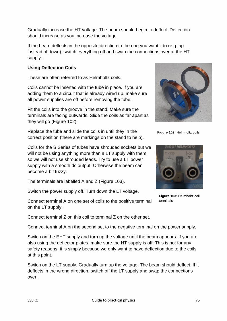
SSERC Guide to practical physics 75
Gradually increase the HT voltage. The beam should begin to deflect. Deflection
should increase as you increase the voltage.
If the beam deflects in the opposite direction to the one you want it to (e.g. up
instead of down), switch everything off and swap the connections over at the HT
supply.
Using Deflection Coils
These are often referred to as Helmholtz coils.
Coils cannot be inserted with the tube in place. If you are
adding them to a circuit that is already wired up, make sure
all power supplies are off before removing the tube.
Fit the coils into the groove in the stand. Make sure the
terminals are facing outwards. Slide the coils as far apart as
they will go (Figure 102).
Replace the tube and slide the coils in until they in the
correct position (there are markings on the stand to help).
Coils for the S Series of tubes have shrouded sockets but we
will not be using anything more than a LT supply with them,
so we will not use shrouded leads. Try to use a LT power
supply with a smooth dc output. Otherwise the beam can
become a bit fuzzy.
The terminals are labelled A and Z (Figure 103).
Switch the power supply off. Turn down the LT voltage.
Connect terminal A on one set of coils to the positive terminal
on the LT supply.
Connect terminal Z on this coil to terminal Z on the other set.
Connect terminal A on the second set to the negative terminal on the power supply.
Switch on the EHT supply and turn up the voltage until the beam appears. If you are
also using the deflector plates, make sure the HT supply is off. This is not for any
safety reasons, it is simply because we only want to have deflection due to the coils
at this point.
Switch on the LT supply. Gradually turn up the voltage. The beam should deflect. If it
deflects in the wrong direction, switch off the LT supply and swap the connections
over.
Figure 102: Helmholtz coils
Figure 103: Helmholtz coil
terminals

SSERC Guide to practical physics 76
Beam Control
We have seen that the beam can be deflected by applying an HT voltage across the
plates (electric field deflection) or by a current in the coils (magnetic field deflection).
Increasing the HT voltage increases the deflection. Increasing the LT voltage
increases the current in the coils, also increasing the deflection.
The EHT voltage also affects the amount of deflection. With the LT and HT supplies
off, increasing the EHT voltage appears only to make the beam brighter. The reason
the beam is brighter is that the electrons have more energy. A higher "gun" voltage
accelerates them to a greater speed.
It is fairly easy to work out that fast moving electrons will spend less time between
the deflector plates so won't be deflected as much. Working out what happens when
gun voltage is increased when coils are used for deflection is more complicated.
D Series Tubes
Many schools still have the older D Series tubes. These
have an upright stand rather than the angled holder with
labelled sockets. D Series tubes cannot be used in S
Series stands and vice versa.
Looking at the picture, we can see that older D Series
tubes had protruding 4 mm terminals. It was common
practice to connect to those by reversing a stackable 4
mm lead on to them. This is no longer acceptable (Figure
104). In the particular case of HT connections, it is
astonishing that it was ever thought to be a good idea.
The distributors of Teltron tubes still sell the D Series, but
with a collar that prevents this type of connection. The
collars are available as an add-on for older tubes, as are
safety leads (Figure 105). SSERC can help you identify
the parts you need.
Figure 104: this is no longer
acceptable
Figure 105: this collar is now
fitted to the D-Series and can
be retrofitted at school.

SSERC Guide to practical physics 77
Once you have made these adaptations, there is no reason not to keep using these
tubes. We also recommend fitting shrouded sockets (figure 56) to the rear of the
tube (heater and cathode connections). If you are using an HT supply to the cathode,
you don't have an option. You must use shrouded sockets and leads.
The distributors have produced very clear documentation
showing how to connect Teltron tubes. This is freely
available on line. SSERC can help you to access it.
The pictures below show the beam in the Dual Beam Tube. They are included simply
because they are beautiful (Figures 107 and 108).
Figure 106: retro-fitted
shrouded connectors to
cathode / heater.
Figure 107: helical beam
path in Dual beam Tube
Figure 108: circular beam in
Dual Beam Tube

SSERC Guide to practical physics 78
Common Tubes in Schools
Tube Uses Comments
Maltese Cross Create a shadow of a
Maltese Cross on a
screen to demonstrate the
production of "cathode
rays" i.e. electron beams.
Coils can be used to alter
the pattern.
Requires an EHT supply
for the gun and a LT
supply if coils are used.
Perrin Tube Show that the gun
produces a beam of
negative charges.
Lissajous figures.
Deflection using electric
and magnetic fields.
Lissajous Figures (not
covered in our course).
Calculation of e/m*
Requires an EHT supply
for the gun and an HT
supply if deflection plates
are used. If this is the
case, shrouded leads and
sockets must be used. An
LT supply is required if
coils are used.
Thomson Tube (S Series) Electric and magnetic
deflection. Calculation of
e/m.
Requires an EHT supply
for the gun and an HT
supply if deflection plates
are used. If this is the
case, shrouded leads and
sockets must be used. An
LT supply is required if
coils are used.
Electron Deflection Tube
(D Series)
Electric and magnetic
deflection. Calculation of
e/m.
Requires an EHT supply
for the gun and deflection
plates, if used. An LT
supply is required if coils
are used.
Dual Beam Tube Electric and magnetic
deflection. Calculation of
e/m. Helical movement of
electrons (not covered in
this course but see
photos above).
Has two guns and
deflector plates. All
require HT. Shrouded
leads must be used.

SSERC Guide to practical physics 79
*The calculation of e/m - the ratio of the charge to mass of an electron - is a popular
Advanced Higher investigation.
Some schools still have diode and triode valve tubes but these do not feature in
current courses.

SSERC Guide to practical physics 80
Section 15: EHT and Discharge Tubes
Some discharge tubes (also called spectral lamps)
need special power supplies, for example sodium
lamps. Others can run from an EHT supply. If you
are going to do this, it is best to use them in a
proper holder (Figure 109).
The one in our picture has a metal rod that can be
attached using a screw. This enables the holder to
be mounted in a clamp stand.
Slide the ends with the sockets so that the metal
caps on the tube fit into the clips.
Hold the tube in place using the straps, as shown
(Figure 110). We've left the mounting rod off just to
make photography easier.
If you look closely, you will see that we have
used a piece of adhesive tac to make the set up
less rickety. Mount the tube holder in a boss head
(Figure 111).
Make sure the power supply is switched off. Turn the voltage
down.
Connect the tube to the power supply. It doesn't matter which
way round you make the connections.
Switch the power supply on and gradually turn up the voltage.
At a particular voltage, the lamp should come on. Don't be
surprised if the voltage on the display drops when this
happens.
You can now look at the light from the tube through a
spectroscope (Figure 112).
Figure 109: discharge tube holder
Figure 110: securing the tube with straps
Figure 111: tube and holder mounted
and connected
Figure 112: spectrum from helium tube

SSERC Guide to practical physics 81
Section 16: Detecting Radiation
This section is not about handling radioactive sources. Instead, this is about using
common instruments used for detecting radiation. We'll also suggest some
experiments that you can do with them that use materials that don't require special
handling. If you are running a "Laboratory Skills" course, you might find these
activities to be worth incorporating.
In this section, when we say "radiation" we should really say "ionising radiation" to
distinguish it from other forms such as visible light, UV etc.
Geiger-Müller Tubes
If you asked a member of the public to name a radiation detector, they would
probably say "a Geiger counter". Every Geiger counter consists of the counter itself
and a Geiger-Müller (GM) tube. Radiation enters the tube through a thin window.
Inside the tube is a low pressure gas and an electrode. The radiation interacts with
the gas, creating a pulse at the electrode. This pulse is counted.
Below are three common tubes used in schools.
Figure 114
Figure 115
Figure 116
ZP1481 tube in holder.
The tube is stored with a
protective end cap in
place. Here, it has been
removed before the tube
is used.
This Frederiksen tube also
has an end cap. The cap
has a small hole to allow
air to escape when it is
fitted, otherwise the tube
would burst. Be careful not
to cover this hole with your
finger when refitting the
tube. Frederiksen tubes
are also used by some
interface manufacturers
(for example, Pasco, Alba
and Data Harvest).
SEP produce this
combined tube and
counter.
GM tube windows have to be thin to let radiation through. Handle with great care.

SSERC Guide to practical physics 82
Know Your Connectors
GM tubes come with different connectors (Figure 117). On
the left, we see a BNC connector which is a "push and
twist" bayonet fitting. On the right is a PET 100 "push and
screw" connector. They are not interchangeable. Adaptor
leads are available.
Common Counters
This counter is made by Philip Harris and can
connect to a GM tube or to light gates. (Figure
118).
GM tubes run at a high voltage but the system is
very safe and requires no special control measures. They have an
optimum voltage. Usually, setting the control to 400 V is fine (Figure
119). If you do this and it doesn't count, turn it up little by little until it
does.
To begin counting, plug in the tube,
switch the counter on and set the
Function switch to counting (Figure
120).
Flick the silver switch to start.
We usually count for a certain time
period. When it is over, flick the
switch to stop.
To start counting afresh, press Reset
and return the switch to the start position.
Figure 67: BNC (left) and PET 100
connectors
Figure 118: Philip Harris counter
Figure 119: GM
tube voltage
control
Figure 120: Philip Harris counter controls

SSERC Guide to practical physics 83
The SEP counter is more straightforward. There is an On/Off
switch (not shown in the picture, but hard to miss) and a Reset
button (Figure 121). Switch on, time using a stopwatch and
reset when you are ready to take a new count.
This Unilab counter (Figure 122) is more complicated than both
the SEP and Philip Harris units.
Make sure that the yellow control is turned to Radioactivity
(Figure 123).
Connect the GM tube.
Make sure the switch that says g.m s.s.d is set to g.m.
Set the voltage control to 400 V. You can turn this up if it
doesn't register any counts when you begin.
If the audio on switch is in the position shown, you will hear a
chirp every time radiation is detected.
Figure 121: SEP combined
tube and counter controls.
Figure 122: Unilab counter
Figure 123: essential controls
to get the Unilab counter
operating.

SSERC Guide to practical physics 84
Set the blue control to freq rate (Figure 124)
Set the little switch to single reading.
The red control lets us set the counting time. For
example, turning it fully anticlockwise will make it count
for 1000 seconds then stop. Turning it one notch
clockwise reduces this time to 100 seconds, another
notch 10 seconds and so on.
Ignore decimal points.
If you want to time manually, make sure the little switch
shown in Figure 125 is in the up position. Set the blue
controller to count. Use the start / stop button to start or
stop counting.
Whatever mode you are using, you can tell if the device is
running by looking at the red LED. When it goes out, the
counting period is over (or you have manually stopped it).
The hold button freezes the display but does not stop
counting.
Figure 124: setting the counting period
Figure 125: more controls

SSERC Guide to practical physics 85
Measuring Background Radiation
You may have noticed that in all our pictures of GM tubes and counters, there is a
reading on the counter despite there being no obvious radioactive source present.
This is due to background radiation. Radioactivity is a natural phenomenon that we
cannot avoid. Radioactive substances are present in:
Rocks
Soil
Building materials
Foodstuffs
The atmosphere (in particular, radon gas)
Cosmic rays also account for some of the dose of radiation that each person
receives.
Additionally, everyone receives a dose of radiation due to human activities - nuclear
power plants, nuclear weapons deployment and testing, and medical procedures.
If you set up a GM tube and counter and let it run for 100 seconds, you will get a
reading. It will probably be between 20 and 40 counts in this time. Note that some
parts of Scotland are more radioactive than others. If you now repeat the activity, you
will probably get a reading in the same range, but it is unlikely that it will be exactly
the same. Radioactivity is a random process. Working in this field often involves
statistics - taking averages and so on.
Potassium Compounds
A small percentage of potassium is radioactive. It is
impossible to isolate or avoid this but it poses a negligible
risk. Schools can work with potassium compounds without
taking any special control measures. Some foods are rich in
potassium, for example bananas and LoSalt®.
We can show this by putting a few grams of potassium
chloride (KCl) into a cupcake case (Figure 126), watch glass
or similar and place a GM tube close to, but not touching the
compound. When we measure the count over 100 seconds,
we should be able to see that it is significantly above the
background count taken over the same time interval.
It is also worth comparing this with the count from the same mass of sodium
chloride.
Figure 126: GM tube and
KCl.

SSERC Guide to practical physics 86
Brazil Nuts
Brazil nuts are also mildly radioactive. We crushed a few into a mortar dish and the
number of counts in 100 seconds proved to be greater than background. However, it
turned out that the mortar dish was also mildly radioactive. When we tried the nuts
on their own, the readings we got in 100 seconds did not prove the nuts were
radioactive. We tried repeating readings and taking an average but again the
randomness of radioactivity meant that we could not say for sure that there was an
elevated level or radioactivity in the Brazil nuts. In the end, we had to use counting
intervals of 1000 seconds.
Radioactivity Theory - For Interest
Radioactivity is all about events taking place in the nuclei of atoms. We know that an
atom's nucleus contains protons and neutrons and that it is the number of protons
that determines what the atom actually is. If it has 19 protons, for example, it is
potassium. Most potassium atoms have 20 neutrons in their nuclei but some have
21. The latter nuclei are unstable- the ratio of protons to neutrons is not quite right for
the nucleus to remain as it is forever.
A nucleus can become more stable by emitting radiation in the form of a particle.
When we say "particle" we include high energy photons. Once the particle has been
emitted, we say that the nucleus has decayed (Figure 127).
Depending on the particle emitted, the nucleus may now be that of a different
element. For example, unstable potassium nuclei may decay and turn into calcium. It
depends on the type of particle emitted.
We've said "daughter nucleus" rather than "stable nucleus" because there may be
further decays. The daughter nucleus may also be radioactive.
There are three main types of radioactive decay, called alpha, beta and gamma.
Whilst it is usual to talk about alpha particles and beta particles, we usually say
"gamma photons". If we're talking about the radiation as a whole rather than from a
single decay, we may say "gamma rays".
Particle Decays
Daughter
nucleus
+
Unstable
nucleus
Figure 127: radioactive decay.

SSERC Guide to practical physics 87
The activity of a radioactive substance is the number of decays happening every
second. Once an atom has decayed, its nucleus has changed so the same thing
cannot happen again. In other words, over time radioactive substances become less
radioactive.
Radioactive decay is a random process. If we could see an individual nucleus, we
could not tell if it was going to decay in the next minute, hour or indeed year.
However, since we are dealing with colossal numbers of atoms at a time, we can
make certain predictions.
Each different radioactive substance has a time associated with it called the "half
life". This is the time taken for the activity to half. Whilst it depends on the substance,
it is completely independent of the mass of radioactive material. Half lives range from
tiny fractions of seconds through to millennia. For example, the half life of potassium
is over a billion years. We won't see a significant drop during a school science
lesson.
Radiation emitted from radioactive substances may cause ionisation. It can charge
the atoms it comes into contact with. This ionisation can cause harm to living cells. It
is also the mechanism by which we detect radiation.

SSERC Guide to practical physics 88
Balloon Experiment (Daughters of Radon)
This experiment was developed by a predecessor in the SSERC Physics team.
Inflate a balloon and suspend it on a line between to
clamp stands. Charge the balloon by rubbing it with a
dry duster or similar (Figure 128).
Leave it for about 45 minutes.
Burst the balloon and put the pieces under a GM tube as
shown in figure 129.
Take the count over a minute and record it. Repeat several times over.
The count rate will fluctuate but should decrease over time.
Explanation
Radon is an unreactive, colourless, odourless gas present in the
atmosphere. Some radon nuclei are unstable. When such a nucleus
emits a radioactive particle, the daughter nucleus may be electrically
charged. This can lead to it being attracted to and adhering to the
charged balloon.
The daughter nuclei have short half lies. Measuring the count rate from
the balloon fragments should show that it is radioactive but that the
count rate is falling as more and more atoms have decayed.
Corrected Count Rate
In some radioactivity experiments we need to start by finding the background
radiation. This is then subtracted from readings taken with the substance in place,
giving the corrected count rate.
Example:
Average background count rate = 24 counts per 100 seconds
Count rate with balloon in place = 138 counts per 100 seconds
Corrected count rate = 138 - 24
= 114 counts per 100 seconds
Figure 128: a charged balloon.
Figure 129: GM tube and
balloon

SSERC Guide to practical physics 89
The Cloud Chamber
The cloud chamber was invented by CTR Wilson, until recently the only Scot to
receive the Nobel Prize for Physics. It is an instrument for detecting radiation, which
creates wispy trails in the device.
In 2015, SSERC gave each local authority a
cloud chamber (Figure 130) on permanent
loan. To create the conditions for the vapour
trails requires the base of the chamber to be
very cold compared with the top. In some
cloud chambers, this is done using solid
carbon dioxide. The SSERC-supplied
chamber uses electrical cooling and requires
only the addition of some isopropyl alcohol
(propan-2-ol) each time it is used.
The kit is supplied with a piece of thoriated TIG welding rod.
Thorium is radioactive and, if small amounts are added to
tungsten inert gas welding rods, the quality of the weld is
improved. The activity of the rod is low - it is no more radioactive
than the average person - so no special controls are needed.
Having said that, if your school borrowed the cloud chamber and
you had a radioactive source cabinet in the building, it would
make sense to keep the rod there for the duration. Handle it by
the end caps, as shown in Figure 131.
Figure 130: electrically cooled cloud chamber
Figure 131: thoriated TIG
welding rod

SSERC Guide to practical physics 90
Using the cloud chamber
Figure 132
Place the TIG welding rod
in the base of the
chamber.
Turn the top to open the
slots.
Figure 133
Add the propan-2-ol to the
felt pad. Don't add too
much - it should not be
running down the walls of
the chamber or dripping
from the top. We found
about 1.5 ml was fine.
Figure 134
Close the slots. Switch
on the cloud chamber
and the LED. After two
minutes or so, you
should begin to see
tracks. This works best in
low light conditions.
Even without the TIG rod in place, you should be able to see tracks. These will be
due to cosmic rays reaching the earth from space.
You can use school sealed radioactive sources with the cloud chamber. Some are
small enough to be placed in the chamber.
Cloud Chamber Theory - For Interest
In an earlier theory section, we spoke about alpha and beta particles and gamma
photons causing ionisation. This was another way of saying that they could
electrically charge the atoms they interacted.
A cloud chamber creates the conditions where clouds are just about able to form. A
charged atom can act as a "seed" that brings droplets together, so a trail forms along
the track where ionisation was caused.
Alpha particles are the best ionisers, gamma photons the poorest. Unfortunately,
alpha particles cannot penetrate the walls of the cloud chamber, so any alpha-
emitting source has to be inside it.

SSERC Guide to practical physics 91
Rules For Working With Radioactive Materials - For Interest
(These rules do not apply to potassium compounds, Brazil nuts, balloons etc)
By including these rules, we are not implying that we would expect technicians
should have sole responsibility for record keeping or indeed any other aspect of
working with radioactive sources.
• Never directly handle radioactive sources unless the source has been
designed to be handled.
• Handle sources with tongs, tweezers or handle.
• Carry the source in its box or pot on a tray.
• When using a sealed source, do not direct the source at yourself or anyone
nearby. While manipulating the source, stand to the side of, or behind, the
source. When the source is in use, stand back.
• When using a beta source, screen the source with Perspex.
• Keep sources in the locked store except when in use.
• Make a record in the logbook of every usage of radioactive substances.
• In any class where pupils are under the age of 16, practical work with
radioactive sources is restricted to teacher demonstrations.
• Before any student can work with radioactive sources, they must be informed
of the working procedures, shown what to do and supervised throughout.
• If a student wishes to do project work with radioactive substances, a risk
assessment must be made, but you do not need to estimate the dose to the
student, or others who may be affected by the work.
• Trainee teachers must be supervised all the time.
• Check stock monthly (except in the summer holidays), keeping a record in the
logbook.
• Test sources for leakage at least every 2 years.

SSERC Guide to practical physics 92
Section 17: Vacuum Pumps and Bell Jars
Vacuum pumps and bell jars are used in a number of experiments. The most
common ones are:
• Demonstrating the effects of low pressure;
• Showing that air has mass;
• Demonstrating that sound cannot travel through a vacuum.
When working with vacuum apparatus, the greatest hazard is implosion - the air
pressure outside the apparatus is so much greater than that inside that it can cause
the bell jar to collapse in on itself, sending glass or plastic shards flying. This can
cause major cuts or eye damage. The energy of an implosion is proportional to the
volume of the vessel, so using a small vessel reduces the risk.
Working with Microscale Apparatus
The first and second of these can be demonstrated
using a piece of kit called the Microscale Vacuum
Apparatus (also called the Student Bell Jar).
The jar and the base it sits upon are made of
polycarbonate. A syringe and a system of valves are
used to extract air, dropping the pressure inside the
jar (Figure 135).
A sealed balloon can be placed
inside the jar and "inflated" by
extracting the surrounding air
(Figures 136 and 137).
This also works beautifully with a
marshmallow.
Figure 135: Microscale vacuum
apparatus
Figure 136: tie up a balloon Figure 137: inflate by extracting
the air around it

SSERC Guide to practical physics 93
If hot water from a freshly-boiled kettle is placed in a container inside the jar,
it can be made to boil again by reducing the pressure around it (Figure 138).
We can show that air has mass by fitting the tap accessory to the
apparatus. We find its mass on a balance that reads to 0.01 g
or better. If we then extract some air and close the tap (Figure
139), when we disconnect and find the mass again, it should
have decreased.
Note that the experiment where the mass of a balloon is found
before and after inflation is not a credible one to find out
whether air has mass.
Microscale Vacuum Safety
Check the apparatus for flaws and cracks before use. Use only the supplied syringe
to evacuate the Student Bell Jar. Never use an electric vacuum pump. Always use
the jar with its base. On no account place the jar on skin and extract air.
Figure 88: boiling
water
Figure 139: air tap on Student
Bell Jar

SSERC Guide to practical physics 94
Full-Sized Vacuum Apparatus
The above experiments can be carried out using full-sized apparatus. As we said,
larger volumes mean a greater risk of severe cuts or eye damage. It follows that our
control measures will be more stringent.
Types of Jar
Most glass vessels are made of soda lime glass.
When this glass breaks, it does so into large
shards. This makes it unsuitable for vacuum
experiments. Borosilicate glass breaks into small
pieces, making it suitable for bell jars. Plastic bell
jars are also available. Make sure that they are
designed for vacuum work.
Safety
When using full-sized bell jars, always:
• Use a jar made of a suitable material (see
above). Conical flasks should never be
used;
• Wear eye protection;
• Use a safety screen;
• Keep pupils at a distance of 2 metres;
• Use tape or a mesh on jars whose volume is greater than 1 litre to restrain
fragments in the event of an implosion;
• Check apparatus for cracks and flaws (especially star cracks) before use;
• Never positively pressurise a vessel (never pump air into it).
Other control measures will be given for specific experiments when necessary.
Sound in a Vacuum Experiment
This is a popular and important experiment (Figure 140). Pupils, having carried out
activities illustrating that sound can travel through solids, liquids and gases, are
shown a demonstration where a sound is produced in an environment where there
are no particles. In truth, "no particles" is not quite accurate, as we shall see.
The apparatus uses a bell jar suitable for vacuum work which has a bung fitted with
two conducting rods. A bell dangles from the rods which are connected to an
Figure 140: full-sized bell jar apparatus, set up to
show the "sound in a vacuum" experiment.

SSERC Guide to practical physics 95
external power supply. The bell jar sits on a base which has a fitment for a vacuum
pump, usually via a tap that can be opened or closed.
When the power supply is switched on, the bell can be heard ringing. As air is
extracted, the bell sounds quieter and quieter until it cannot be heard above the
noise of the pump. At this point, the teacher switches off the pump and disconnects it
after closing the tap.
It is probable that the bell can still be heard very faintly. The main reasons for this
are:
• It is impossible to extract all the air from the jar;
• Some vibrations will travel through the wires suspending the bell.
Making sure there is a good seal between the bell jar and base will help with the first
situation. Vacuum grease will be better than petroleum jelly for maximum air
extraction, but petroleum jelly is what most schools will have to hand and the
experiment works well using it.
The bell can still be seen to be working. This is an important point. Extracting the air
has not affected the bell, only the ability for sound to travel. Secondly, we see that
light is not affected by the removal of air, otherwise the bell would become harder to
see as well as hear.
If the tap is opened slightly to allow air back in, the sound from the bell will become
louder with time. Most pupils will accept that if we could extract all the air and
completely isolate the bell it would be impossible for sound to travel. There is a little
more physics going on here than we are letting on.
You may remember the film Alien being promoted with the line, "In space, no one
can hear you scream!" Sound cannot travel through the vacuum of space (but light
can).
There are two reasons why we do not simply sit a self-contained bell or buzzer unit
on the base of the jar for this experiment. One is that too much sound would escape
through vibrations being passed through the base. The other is a safety reason. A
self contained unit would have to have batteries and these should not be put in a
vacuum chamber. It could cause them to burst.
Do not leave the jar connected to the pump after the air has been extracted. When
we did this, our apparatus drew oil from the pump into the jar. This was very messy.

SSERC Guide to practical physics 96
Looking After Your Vacuum Pump
Most vacuum pumps require oil to work. There are
two checks you should make if the pump has not
been used for a while.
• Is there enough oil?
• Is it clean?
How you check will depend on the model of pump.
One example is given in Figure 141.
Do not run your pump for more than a couple of
minutes if it is not connected to anything and do not use it in a dusty environment.
This will help prolong the life of your pump and will keep it effective. Top up or
replace the oil as necessary, using only recommended vacuum oil.
Figure 141: check your vacuum
pump oil


![Gerador de Van de Graaff...[1]](https://img.dokumen.tips/doc/110x75/55721341497959fc0b91ee5a/gerador-de-van-de-graaff1.jpg)


