Embed Size (px)
Citation preview
Page 2
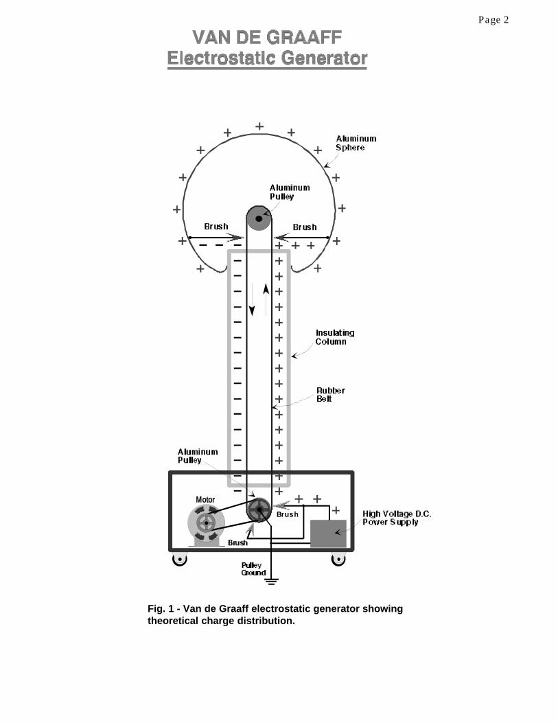
Fig. 1 - Van de Graaff electrostatic generator showingtheoretical charge distribution.
Motor
Brush

Page 3
HIGH PERFORMANCEVAN DE GRAAFF GENERATORS
Van de Graaff Generators are a “must” for any science museum, physics classroom, orexperimenter’s lab. The generators produce high voltage electrostatic charges for entertainingdemonstrations of electrostatic induction, attraction and repulsion, spark discharge, capacitance,and more.
Unlike the Tesla Coil, which produces a continuousbarrage of loud, writhing sparks, the Van de GraaffGenerator quietly builds up a d.c. charge on itsmetal sphere, or collector, over several seconds. Thecharge can then be drawn to an electrode in theform of a lightning-like spark or used in a variety ofexperiments.
Since the generator’s collector can only hold a verylimited charge, even at a very high voltage, theamount of energy the generator can deliver is small.Except for the very large machines, Van de GraaffGenerators are generally quite safe.
Triboelectric, or friction, Van de Graaff Generatorscommonly found in classrooms and science muse-ums can perform quite well under good conditions.However, when the humidity of the surroundingatmosphere increases, the machines’ performancewill rapidly degrade, or they will cease to workaltogether.
This manual will show design and constructiontechniques for Van de Graaff Generators that willdeliver good output even under conditions of highhumidity, and which will deliver superior perfor-mance when conditions are favorable.
Detailed plans for a small (4' tall) Van de Graaff Generator are included, as well as design param-eters that will allow the builder to construct a generator of virtually any size.
HISTORY
The Van de Graaff Generator was invented in the Princeton University labs around 1929 by RobertJ. Van de Graaff. He had used Wimshurst machines to generate positive ions for experiments, butrealized that he needed far higher potentials.
Around 1933, while at M.I.T., he constructed his giant “twin” generator (Fig. 3-D) in a dirigiblehangar in Dartsmouth, Massachussetts. Another large generator, built by Van de Graaff in 1931, isnow housed in the Boston Museum of Science, where it is used for daily shows.
Fig. 2 - This science-show Van de Graaff Genera-tor can deliver a spark over 48" long. The gen-erator is 10' tall and has a 42" diameter collector.The author constructed the machine in 1988 forThe Science Place museum in Dallas, Texas.

Page 4
Supposedly, the first electrical generator was a device constructed by Otto Von Guericke in the 17thcentury in Germany. His “generator” was simply a ball of sulphur on a stick. When the ball wasrotated and a hand or leather pad was brought into contact with it, the friction created static elec-tricity.
Later machines used rotating glass cylinders (Fig. 3-A), then rotating glass disks. Many permuta-tions of the basic friction machine occurred as experimenters tried to increase the voltages andcurrents their apparatus could produce.
Electrostatic devices using belts to carry charges may have existed prior to Van de Graaff’s genera-tor, but he is the one who deserves credit for first developing large, effective machines for seriousresearch into nuclear physics.
Van de Graaff Generators are still used today to provide ion sources for nuclear accelerators and, insome cases, to serve as the principal accelerator. These generators are housed in pressurized, gas-filled tanks to allow higher voltages than could be achieved at normal atmospheric pressure.
Fig. 3 - (A) Eighteenth century electrostatic generator consisted of a rotating glass sphere charged byfriction between a hand and the glass. (B) James Wimshurst invented his famous electrostatic generatoraround 1880. A crank turns two contra-rotating disks having metal sectors. (C) This large Holst generatorcould produce 30-inch discharges. (D) Robert Van de Graaff built his giant "twin" generators around 1933.The collectors were 15' in diameter; insulating columns were 24' high and 6' in diameter. They were housedin a dirigible hangar. (From The Electrical Experimenter, 1915, The Burndy Library, and The ScientificAmerican, 1934.)
BA
C D
Page 5
THEORY OF OPERATION
Classical explanations of Van de Graaff Generator operation usually state that electrical chargesare deposited on a moving belt, and that the belt transports the charges to a metal Collector wherethey are picked off and arrange themselves on the Collector’s surface (Fig.1).
The following theories elaborate a bit further and are based on the author's experience.
Friction Excited Van de Graaff Generators
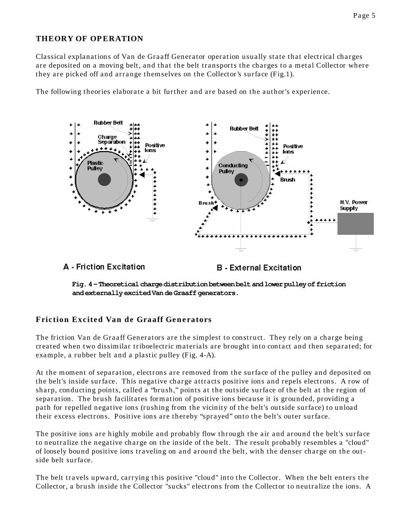
The friction Van de Graaff Generators are the simplest to construct. They rely on a charge beingcreated when two dissimilar triboelectric materials are brought into contact and then separated; forexample, a rubber belt and a plastic pulley (Fig. 4-A).
At the moment of separation, electrons are removed from the surface of the pulley and deposited onthe belt's inside surface. This negative charge attracts positive ions and repels electrons. A row ofsharp, conducting points, called a “brush,” points at the outside surface of the belt at the region ofseparation. The brush facilitates formation of positive ions because it is grounded, providing apath for repelled negative ions (rushing from the vicinity of the belt's outside surface) to unloadtheir excess electrons. Positive ions are thereby “sprayed” onto the belt's outer surface.
The positive ions are highly mobile and probably flow through the air and around the belt's surfaceto neutralize the negative charge on the inside of the belt. The result probably resembles a "cloud"of loosely bound positive ions traveling on and around the belt, with the denser charge on the out-side belt surface.
The belt travels upward, carrying this positive "cloud" into the Collector. When the belt enters theCollector, a brush inside the Collector "sucks" electrons from the Collector to neutralize the ions. A
Fig. 4 - Theoretical charge distribution between belt and lower pulley of frictionand externally excited Van de Graaff generators.

Page 6
Collector
Conducting Pulley
BrushConducting Pulley
Plastic Pulley Covered With Vinyl Tape
Brush
Brushes
Belt Belt
Conducting Pulley
Brush
Brush
H.V. Power Supply
BA
Fig. 5 - Recommended Brush/Pulley combinations for friction (A) andexternally-excited (B) machines.
positive charge thereby builds on the Collector's surface. Even though the voltage on the Collectorclimbs to many times that of the belt, the charge continues to build because the density of thecharge is lower on the Collector.
As the belt leaves the Collector, it obviously carries a lower positive charge than when it entered.Conventional depictions of Van de Graaff Generator charge distribution usually show a negativecharge on the belt as it leaves the Collector. My measurements show that the charge is positivewith respect to ground, and I've indicated this in Fig. 4.
When the belt approaches the bottom pulley, the triboelectric effects are sufficiently strong to placea temporary negative charge on the inside of the belt, so the charging process continues.
One pulley should be made of a conducting material, like aluminum. The other (friction) pulleyshould be made of a good insulating material, like Plexiglas. The Collector brush in friction ma-chines seems to work best when placed near the center of the pulley. I don't have a theory to ex-plain why.
Collector polarity is determined by the materials used and whether the friction pulley is at the topor the bottom. For example: A common combination is a belt made of rubber and a pulley wrappedwith vinyl tape. If the pulley is in the top of the generator, the Collector will be charged negatively;if it is in the bottom, it will charge positively.

Page 7
External Excitation
Externally excited machines use a high voltage power supply to spray ions onto the belt. Becausetriboelectric effects can hinder the charge transfer, both pulleys should be made of conductingmaterial.
If the power supply voltage is positive, positive ions will be formed by the lower brushes andsprayed onto the belt (Fig. 4-B). A negative charge is supplied by the grounded pulley. The nega-tive charge attracts the positive ions, leaving a positive charge on the outside surface of the belt.
When the belt and pulley separate, positive charges migrate to the inside surface of the belt, cancel-ling the negative charge residing there, as they do in the friction machine.
Somewhat mysteriously, performance is enhanced by the addition of a second brush placed at aboutthe pulley's 230 degree mark. Perhaps this arrangement works because this second, or "auxiliary"brush causes a denser charge on the belt, producing a denser cloud of ions when the belt separatesfrom the pulley.
As the belt enters the Collector, a brush picks off the positive ions, building a positive charge on thesurface of the Collector. The author's experiments have shown that a second brush, located oppositethe first, on the down side of the belt, improves performance. For some reason, a brush located inthe center of the pulley gives poor performance. Usually, performance is slightly enhanced if theupper pulley makes electrical contact with the Collector.
FACTORS AFFECTING PERFORMANCE
COLLECTORS
The theoretical maximum voltage the Collector can develop is 70,000 times its radius in inches.However, allowance must be made for the hole through which the belt travels. The "average" ma-chine will lose around 20% of its maximum potential to this entrance hole. A generator with a 12"diameter sphere would then develop approximately 336,000 volts under good conditions.
A smooth Collector surface is essential, but polishing to a mirror finish helps very little (some say aslittle as 1% voltage increase). The most important considerations are that the Collector be clean,have no sharp protruding edges, and that the entrance hole be properly radiused.
The Collector entrance hole edge radius should be generous; about 8% to 10% of the Collector'sradius (Fig. 6). A 12" diameter Collector, for instance, should have an entrance hole with an edgeradius no smaller than 1/2".
Several different shapes can be used successfully. The author has experimented with shapes A, B,and C, in Fig. 6. Whether a sphere or "spheroid" is used, leakage along the column appears to beadditionally reduced if the bottom of the Collector is slightly flattened (Fig. B & D). Otherwise, aplain sphere is hard to beat.
The diameter of the entrance hole should be no larger than around one-half the diameter of theCollector. Entrance holes smaller than one third the diameter of the Collector will limit the beltsize too much. A wide belt allows the charge to build more rapidly and reduces the effects of leak-age.

Page 8
Fig. 6 - Cross sections of various Collectorshapes showing radiused support column en-trance holes.
Fig. 7 - Removable sphere halves with attach-ment lip rolled on lower half.
Sometimes it is desirable that the top of the sphere be detachable. In this case, any lip or attach-ments should be on the inside, so the sphere retains a smooth surface (Fig. 7).
A removable hemisphere allows for a slightly wider belt to be used, which is good for performance.However, if portability is important, it's usually much more convenient to use a permanently as-sembled sphere that slips easily on and off the support column.
Most Collectors are made of spun aluminum hemispheres (see Appendix for sources). If the twohalves are to be permanently attached, theycan be epoxied or welded together. The seammust be sanded smooth and polished.
Inexpensive Collectors can sometimes befashioned from aluminum or stainless steelsalad bowls or something similar. Lips,handles, or other protrusions will need to beremoved and the surface sanded and polishedsmooth.
Techniques for hand-finishing aluminum orstainless steel hemispheres, including cuttingand radiusing the column entrance hole, arecovered in the construction section.
BELTS
Belts can be made of a variety of materials,but I recommend gum rubber. Neopreneserves very well but lacks "memory," that is,it tends to stretch and not snap back as wellas gum rubber. Latex rubber works fine, butis much more expensive.
I've never tried silk or nylon, although they'resupposed to work fairly well. They're prob-ably not worth the trouble, as they tend tofray and have little elasticity.
The belt should be as wide as possible, asgreater width means the Collector will chargefaster. The belt/pulley combination must bechosen carefully so the belt fits inside thecolumn with adequate clearance.
Chemical engineer Franklin B. Lee, whoexperimented with Van de Graaff Genera-tors, wrote that 50 square inches of belt persecond passing over the pulleys produces onemicroampere current delivered to the Collec-

Page 9
tor. This finding seems to agree fairly well with my own measurements. Maybe this is some sort of"universal constant" for Van de Graaff machines.
The belt should be fairly tight. A rule of thumb for gum rubber belts 1/8" thick and from one tothree inches in width is that the belt should be approxi-mately three inches shorter than the distance betweenthe pulleys. Belts up to eight inches wide should be aboutsix inches shorter.
I suppose elasticity could vary from manufacturer tomanufacturer, so you may want to use the highly scien-tific method I used to determine the proper belt length...Iwent to the rubber supply company, stretched the mate-rial out by hand and said, "Ok, this is about right!"
If you want to build a horizontal Van de Graaff, as shownin Fig. 8, you'll need the belt to be extra tight to reducesagging.
The belt should be as clean as possible. You can curl itup and wash it in a bucket with dish washing detergent,then rinse well and stretch it out in a clean area to dry.
Gum and latex rubber belts will eventually deterioratefrom the effects of ozone and exposure to light. Expect aheavily used gum rubber belt to last about 2 1/2 years.Latex belts may only last a year.
PULLEYS
Aluminum is the preferred material for conducting pul-leys. Plastic pulleys can be made conducting by wrapping them with aluminum tape, but the tapewill eventually wear out and need to be replaced. Use ball bearings with the pulleys; they're notexpensive, and they're much better than the cheaper sleeve types.
Pulleys should have a crown 1/8" to 1/4" to help keep the belt centered (Fig 9-A). Although a crownis best, an alternative for small generators is to wrap the pulleys in the center with several turns oftape (Fig. 9-B). Use aluminum tape on the conducting pulley, plastic tape on the friction pulley.
Non-conducting pulleys for friction-excited machines can be made from Plexiglas, nylon, UHMWplastic, or any other serviceable plastic. Different plastics will give different levels of performance,but I've found very little experimental comparison data. UHMW, which is similar to nylon, butcheaper and easier to machine, works well with gum rubber. Other experimenters have tried poly-ethylene with success. Vinyl tape wrapped on the pulley surface works very well with rubber belts.
A good combination for small friction machines would be: A friction pulley made of Plexiglaswrapped with vinyl tape, and a conducting pulley made of aluminum or Plexiglas wrapped withaluminum tape.Pulley diameter isn't critical, but it's necessary to compromise between a very small diameter,
Fig. 8 - A horizontal Van de Graaff genera-tor the author constructed for a companyinvestigating effects of static electricity onaircraft components.

Page 10
Crown
Pulley tapered1/8" to 1/4"
Shaft
Tape
A
B
Fig. 9 - To keep belt from wandering, the pulleysshould have a crown (A) or be taped (B).
which would allow for a wider belt, and a larger diameter, which would allow smoother running andless stress on the belt and bearings.
A "rule of thumb" is that the pulley diameter should be about 33% to 42% of the inside diameter ofthe column.
BELT SPEED
The higher the belt speed, the faster the charge buildup on the Collector, and the less susceptiblethe machine will be to current leakage.
However, most of the machines I have built operate at a very conservative speed; one belt revolutionper second for large machines (10' tall) and two revolutions per second for machines up to five feettall. Higher speeds can sometimes cause the belt to wander and pull away from the pulleys. Lowerspeeds may not supply charge fast enough to compensate for leakage, lowering performance.
BRUSHES
Somewhere, there's a perfect design forbrushes. I've tried brass window screen, brassstock cut into a series of points, "whiskers" ofcopper wire, and double brushes (Fig 10). All ofthese approaches seem to work about the same.All that seems to be required is a row of sharp,conducting points placed at the correct locationand distance from the belt. If there are betterdesigns, I haven't found them.
From a practical standpoint, I like to use brassscreen or copper wire whiskers. Brass stockcan damage the belt, and there seems to be noadvantage to using thick or multiple brushesper location.
BRUSH PLACEMENT
Correct positioning of the brushes is critical toperformance (Fig. 5 - A&B). Brush locationsfor friction machines are "standard" and wellknown. However, there's a dearth of informa-
tion about externally excited machines, and I had to experiment quite a bit to arrive at the arrange-ment in Figure 5 - B. More elaborate arrangements have appeared in various publications, but I'vehad no particular success with them.
The precise alignment of the brushes must be determined experimentally, as belt and pulley materi-als, motor speed, and other variables (such as proximity of lower pulley to ground) can alter theoptimum locations. It's a good idea to leave plenty of space to experiment with brush positionswhen designing a generator.

Page 11
Fig. 10 - Three effective brush styles. Brass window screen iseasy to work with; brass sheet can damage the belt; copperwhiskers are very adjustable but more difficult to manage.
A simple analog microammeter can help tremendously when experimenting with brush locations.Connect the meter between the Collector and ground and monitor the current. Maximum currentindicates optimum brush positioning. About one microampere per 50 square inches/second of belttravel should be developed. Don't use a digital or electronic meter! The high voltage will ruin theinstrument very quickly.
The belt is surprisingly efficient in transporting its charge, once the correct brush locations arefound. You can check this out simply by taking a current reading between the power supply andthe lower brushes and then between the Collector and ground. If the system is working well, therewill be very little difference in the two readings.
SUPPORT COLUMN
PVC, Plexiglas, and fiberglass are excellent materials for the support column. PVC is the cheapest.It is strong, easily machined, and comes in many sizes. Plexiglas, although it's expensive andsomewhat fragile, is the preferred material for small to medium size machines. Plexiglas hasexcellent electrical properties and is clear. Plexiglas cylinders are usually sold in six foot lengths.Fiberglass is strong and light, but it can be expensive, and it's doubtful that the correct size andfinish can be found. Paper cylinders and most phenolics will allow far too much leakage.
The distance between the Collector and the base of the generator should be two or three times theCollector diameter. If the column is too close to the base, leakage and sparking along the column'souter surface will become a problem.
POWER SUPPLY
Practical exciter voltages range from around 5,000 to 15,000 for all but the largest machines. Thegiant Van de Graaff Generator in the Boston Science Museum uses 20,000 volts. The machines Ihave built, which range from 4' tall to 15' long (horizontal), use around 10,000 to 15,000 excitervolts.
One of the simplest means of obtaining this voltage is to rectify the current from a 15,000 volt neonsign transformer (Fig. 11). If you're designing a fairly large generator, the size and weight of such atransformer will be negligible. A smaller generator can use a smaller, lower voltage neon signtransformer and a voltage multiplier (Fig. 12).The so-called "core and coil" neon sign transformers are small, cheap, and fairly lightweight. These

Page 12
transformers are usually available with outputs from 3,500 to 6,500 V. However, the secondarymidpoint may be grounded on some units, which will cut the usable voltage in half. If there is nomidpoint ground, one leg of the secondary can be grounded and the full voltage can be used.
Caution: If the grounded leg of a transformer with no midpoint ground loses contact with earthground, it can develop half of the secondary voltage rating and can cause a dangerous shock iftouched. For safety, add a 500 kΩ to one megohm resistor in series with the output. (Oddly, thegenerators seem to work a little better with little or no resistance in series, even though the currentdemand is in the microamp range).
Another approach is to build a power supply consisting of a television flyback transformer or auto-mobile ignition coil, oscillator, and rectifier (Fig. 12). It's difficult to justify the construction effortrequired for these designs, however, because they provide only minimal savings in weight and cost,if any.
Although I've never tried it, a personaldefense "zapper" might be converted into apower supply. They're advertized in maga-zines and sold in various gun stores. I'malmost certain that the output is DC. If not,a high voltage rectifier could easily be added.
The high voltage circuits mentioned aboveproduce dangerous currents that can causeserious shock. If you're not experiencedworking with high voltage, find someone tohelp who is.
When you work on the generator, unplug themachine and short out the power supply toremove any residual charge. If you use avoltage multiplier, you may wish to install a500 meg., 1 watt bleeder resistor across theoutput.
The power supply voltage should be high enough to form a faint corona on the lower brushes' pointswhen viewed in the dark. No sparks should jump to the lower pulley. Sparking reduces themachine's performance and can eventually damage the belt. The distance between the brushes andthe belt can vary from around 1/8" to 1/2".
Five thousand volts will jump about 1/4"; 10 kV about 1/2", and 15 kV about 3/4".
The polarity of the supply voltage will determine the polarity of the Collector, i.e., a positive supplywill produce a positive Collector, and a negative supply will produce a negative Collector.
Fig. 11 - Neon sign transformer used as a high voltagepower supply for large Van de Graaff Generators.

Page 13
Fig. 12 - Schematic for power supply using a typical neon sign trans-former with secondary midpoint grounded to case. Transformers witha secondary rated less than 12 kV will need a voltage multiplier.
Fig 13 - Cascade voltage tripler. Capacitors and rectifiers must havea voltage rating twice the AC peak voltage. Capacitors typicallywould be ceramic, 500 to 2,500 pF.
MOTORS
I prefer 1,725 or 3,450 rpm split phase motors or, for large generators, capacitor start motors.Speed can be varied by changing pulleys or by using a variable speed pulley. Experimenters maywant to use an AC/DC motor so the speed can be easily varied over a wide range. Once a goodoperating speed is determined (see P. 10), there's rarely a need to vary it.
The 4' Van de Graaff Generator described in this manual uses a 1/6 h.p. split phase motor. Thelarge vertical machine pictured on Page 3 uses a 1 h.p. capacitor start motor, and the horizontal Vande Graaff (Fig. 8), because of its wide, tight belt, uses a 2 h.p. capacitor start motor.

Page 14
The high voltage power supply in Fig. 14 consists of an auto ignition coil driven by an electroniccircuit.
Power for the circuit is provided by a 12 V. transformer, full wave rectifier, and filter capacitor (C1).A 555 Timer IC produces positive pulses which switch the power transistor on and off. Each timethe transistor conducts, current pulses through the ignition coil, causing high voltage to appear atthe coil's output terminal. The output can be further increased with a voltage multiplier. Theignition coil's output is regulated by R2 and R5, which control pulse frequency and power, respec-tively.
Ignition coils require experimental adjustment of R2 and R5 for maximum voltage. Output rangesfrom around 4,000 to 10,000 volts, although higher voltages might be produced if one were tostumble across the "perfect" coil and design an improved pulse circuit. The author has used severalvarieties of inexpensive, common, replacement coils for breaker-type ignitions, each yielding aboutthe same voltage.
For more detailed information about using auto ignition coils and TV flyback transformers as a highvoltage source, see "Books and Literature" in the Appendix.
Fig. 14 - Ignition Coil High Voltage Supply. C1 = 1,000 to 2,000 mFd, 35 V; C2 = .01 mFd., 50 V; R1= 330 ohm, 1/4 W; R2 = 100 K; R3 = 100 K, 1/2 W; R4 = 100 ohm, 1/2W; R5 = 5K, 1/2W.

Page 15
MAINTENANCE
Dust, sharp points, and humidity are the enemies of electrostatic generators.
Dust on the Collector and column will rapidly bleed off charge. Hair or lint can frequently becomelodged where the support column enters the Collector. If you can't see the lint or dust, you canprobably hear it hissing and crackling as it bleeds off charge.
Avoid touching the column or belt. Hands and fingers leave oily acids that can render the columnslightly conducting. Stubborn hand prints or dirt can be removed with dishwashing detergent, thenby wiping the surface with rubbing alcohol on a lint-free rag (remember that Plexiglas scratcheseasily). Do not use Windex or similar cleaners that contain ammonia or other electrolytes; they'llleave a conducting film on the column.
Sharp pointed conductors in the vicinity of the generator will bleed away charge. Deep scratches,dings, or gouges on the Collector surface will prevent maximum charge.
Humidity will bleed off charge along the support column and through the air. Humidity also inter-feres with charge deposition on the belt. Sometimes drying the belt and column with a hair dryerhelps reduce the effects of humidity or moisture. I've also tried placing moisture-absorbing silica gelin a porous container inside the base, but I'm not certain how effective this is.
PERFORMANCE SUMMARY
• Use a charge sprayer with an output from 5 kV to 15 kV.• Adjust system to avoid sparking between lower brushes and pulley.• Use the widest belt possible.• Use the largest feasible Collector.• Use a high belt speed.• Make the distance between the Collector and base equal to two or
three times the Collector diameter.• Properly radius the Collector column entrance hole.• Experiment with brush placement.• Keep Collector and column surfaces smooth and clean (do not use
Windex or cleaners containing electrolytes).• Avoid touching column and belt.• Keep belt and pulleys clean.• Keep sharp pointed conductors away.• Keep moisture condensation down with hair dryer if necessary.

Page 16
HOW TO BUILD A4' VAN DE GRAAFF GENERATOR
Fig. 15 - 4' Van de Graaff Generator is de-signed for classrooms and science shows.Unit shown has a 12" dia. Collector.
The 4' tall Van de Graaff Generator described on the following pages can produce from 340,000 to390,000 volts (depending upon the size Collector used) and visible sparks over a foot long. Thegenerator will provide enough charge for demonstrations on humid days, and is an outstandingperformer when conditions are good.
Virtually all of the high performance parameters set forth in the preceding pages are recognized inits design. The rugged, portable machine is perfectfor small science shows and classrooms. TheCollector slides easily on and off the column, andthe instrument can be placed inside a road case forstorage or transport.
COLLECTOR
The Collector consists of a 12" or 14" diameteraluminum flagpole sphere (or flagpole "ball" in thetrade vernacular). The "ball" consists of twohemispheres, the bottom half having a turned-inlip over which the top is placed. The 14" ball ismuch more expensive than the 12", but it will yieldaround 390,000 volts...50,000 more than thesmaller diameter.
The support column entrance hole is cut in thebottom hemisphere and radiused by hand, and thetwo hemispheres are epoxied together.
The support column has a 5" O.D., so the radiusedhole will need to be about 5 3/16" in diameter toallow clearance.
Find the center of the bottom hemisphere. Oneway to do this is to use a piece of #20 copper wireand "guestimate" the distance from the rim to theinside center. Run the wire around the rim, ad-justing the wire until the correct length is deter-mined.
Another way is to mark a 9 1/2" section on a length of wire and run it from the outside of the hemi-sphere to the approximate center. Run the wire from several different locations around the rim,

Page 17
Fig. 16 - Scribe for marking column hole in bottom Collectorhemisphere.
marking each "center." A cluster of marks will show the center. Once the center is found, punch itand drill a 1/4" hole.
Make a scribe as follows: Cut a length of straight wood 3/4" x 3" x 10" long. Drill two 1/4" holesthrough the wood 2 3/8" apart (Fig. 16). The holes must be straight, so a drill press or drill guide isrecommended.
Sharpen the end of a 1/4" x 1 1/2" bolt and insert it into the end hole, with nuts and washers, asshown. Bolt the scribe to the hemisphere and adjust the sharpened bolt until the scribe is level as itrests on the sharp point.
Rotate the scribe and carefully score a circle in the hemisphere's surface. Make the scratch heavyenough that it can be easily seen.
Using a skil saw, cut along the scribed line. The resulting hole should be 4 3/4" in diameter, readyto be radiused.

Page 18
Note: Flagpole balls normally have a thickness of about 1/16" (.0625"). The balls are made from flataluminum stock that is placed over a spinning die or chuck. During the spinning process, a steeltool is pressed against the aluminum, forcing it to conform to the shape of the chuck. The toolcreates a series of shallow, concentric rings in the surface of the aluminum. These rings will notreduce the charge-holding ability of the Collector so long as they are smooth.
FORMING THE COLLECTOR ENTRANCE RADIUS
The entrance radius is created by hammering the edge of the lower hemisphere's entrance holeagainst a radiused wooden die. Because the aluminum is so malleable, this process is easier thanyou might expect.
The die is made as follows: Cut a ring of 3/4" thick plywood measuring 5 5/16" I.D. and 7 3/8"O.D. Screw the ring to a plywood disk 7 3/8" in diameter and, using a 1/2" radius router bit, routthe inside edge of the ring (Fig. 17). The assembly can be secured for routing by screwing it to aworkbench surface. Bevel the outside edge at about a 45 degree angle. This can be done with arouter or with a disk sander.
Cut a plywood disk that will fit snugly justinside the lower hemisphere (about 11 7/8" dia.).This disk will be the bottom of the die.
Using various thicknesses of wood, raise the diejust enough that the hemisphere, when placedover it, just barely touches the workbenchsurface (Fig. 18-C).
Attach the pieces as shown and screw the as-sembly to the workbench surface.
Using a small or medium size ball-peen ham-mer, firmly tap the entrance hole edge allaround the perimeter, forcing it to conform tothe radius of the die (Fig. 18-C). Strike only thepart of the aluminum that should curve backinto the hemisphere.
Remove the hemisphere from time to time to check its fit on the Plexiglas column. The fit should beloose enough that the hemisphere will slide on and off freely.
Remove the hemisphere and file the rough hammer marks smooth with a round file. Use sandpaperto smooth out the file marks.
ASSEMBLING THE COLLECTOR
The two hemispheres are epoxied together so the Collector can be quickly slipped on and off thecolumn. Just about any epoxy, like the common "Two Ton" epoxy, will work. "Five Minute" epoxywill set up too quickly. I prefer a grey paste epoxy, "PC-11" epoxy, which allows plenty of working
Fig. 17 - Top view of wooden die.

Page 19
Fig. A
Fig. B
Fig. C
Fig. 18 - (A) Cross section ofdie (B) Dimensions (C)Hammering hemisphereagainst die to create radius

Page 20
Fig. 19 - Bottom of Collector, showing radiused columnentrance hole.
time and can be smoothed to virtually eliminate the seam.
Clean and lightly sandpaper the two surfaces to be joined. Apply the epoxy to the rolled lip andpress the two halves together. Weights may be needed to keep the halves tightly and evenly to-gether while the epoxy hardens. Wipe off excess epoxy with a rag moistened with acetone.
Before the epoxy hardens, check the conductivity between the two hemispheres with a VOM. Al-though I haven't experienced any conductivity problems, it's possible that the epoxy could acciden-tally insulate one hemisphere from the other. If this happens, it may be necessary to remove theepoxy from the seam and try again.
After the epoxy has cured, carefully file and sand the seam smooth...no sharp edge should protrude.The file marks and scratches around the seam should be wet sanded with 120, 220, and 400 gritsandpaper. If the Collector has any deep or unsightly scratches, wet sand the damage smooth andthen polish as described below.
POLISHING THE COLLECTOR
For appearance, the entire Collector, especially areas that have been sanded, will need polishing.Use a 7", heavy duty 1,950 rpm polisher and a wool buffing pad. Use a fast-cutting polishing com-pound such as 3M fast-cutting machine cleaner. An effective way to hold the Collector steady whilepolishing is to place it on a piece of carpet or soft cloth and kneel, holding the Collector between yourknees. Carefully apply the polisher, rotating the Collector as needed. Use special caution whenpolishing around the column entrance hole, as the polisher can snag the Collector and send it flying!
CONSTRUCTING THE BASE

Page 21
The base is a box made of 3/4" cabinet grade plywood with inside dimensions measuring 20" by 16"by 11" tall (Fig. 20). The top consists of two removable panels of 1/4" Plexiglas. The front of the boxis removable for maintenance and adjustments. The box interior and exterior can be painted,stained and varnished, or covered with Formica.
Use wood screws and glue to assemble the three sides and bottom of the box. The front panel isscrewed on but not glued. If Formica is to be applied to the exterior, it should be done before begin-ning installation of components. If you're applying Formica to the interior, it must be done prior toassembling the box. In case you're not familiar with Formica technique, a cabinet shop should beable to do the job at a reasonable cost.
Cut two braces of 3/4" x 2 1/2" hardwood and install them flush with the top, as shown. Don't gluethe braces in place, as they will need to be removed from time to time when installing and adjustingthe components. They should be stained and varnished.
After the cabinet is constructed, install four swiveling castors (two with brakes).
Cut two panels of 1/4" Plexiglas for the cabinet top (Fig. 21-B). A 5 1/4" diameter hole will be cut inthe front panel to accommodate the Plexiglas support column. An excellent way to cut a clean,precise hole is to use a router and a simple guide, as described below.
ROUTING A PERFECT HOLE
Cut a piece of 1/4" thick Plexiglas or cabinet grade plywood 11" or 12" long and as wide as the baseof the router (Fig. 21-A). Unscrew the router's base plate and use it as a template for drilling holesin the guide so the router can be screwed to the guide.
If the hole you need to cut with the router is 5 1/4" in diameter, measure exactly 2 5/8" from theoutside of the router bit (1/4" bit works best) to a point on the center line of the guide. Drill a 1/4"hole at this point. Countersink the hole and install a 1/4" flat head bolt long enough to go all theway through the material you will be routing. Screw the router to the guide.
Drill a 1/4" hole in the material to be routed; place the guide over the material and insert the 1/4"bolt through the hole. The addition of a nut and washer will help stabilize the guide while the holeis being cut.
Adjust the router so the bit will just penetrate through the material. Loosen the 1/4" bolt enough sothe router bit can be lowered slowly into the material, allowing it to drill its own starting hole. Turnthe router off, tighten the nut on the 1/4" bolt "finger tight", turn the router back on, and slowlyrotate it in a complete circle, cutting a 5 1/4" diameter hole. Proceed very slowly as the bit nears theend of its travel so it doesn't wander as the hole is completed.
This same technique can be used to rout out the clamp that holds the column in place (see below).
COLLAR

Page 22
Fig. 20 - Van de Graaff Generator cabinet

Page 23
A
B
Fig. 21 - (A) Making a Router Guide that will allow cutting perfect circles. (B)Two Plexiglas panels that comprise the top of the cabinet. The 5 1/4" hole is forthe Plexiglas column.

Page 24
Fig
. 22
- P
lexi
gla
s C
olla
r m
ou
nts
to
to
p o
f ca
bin
et a
nd
tig
hte
ns
aro
un
d t
he
colu
mn
, ho
ldin
g it
fir
mly
in p
lace
.

Page 25
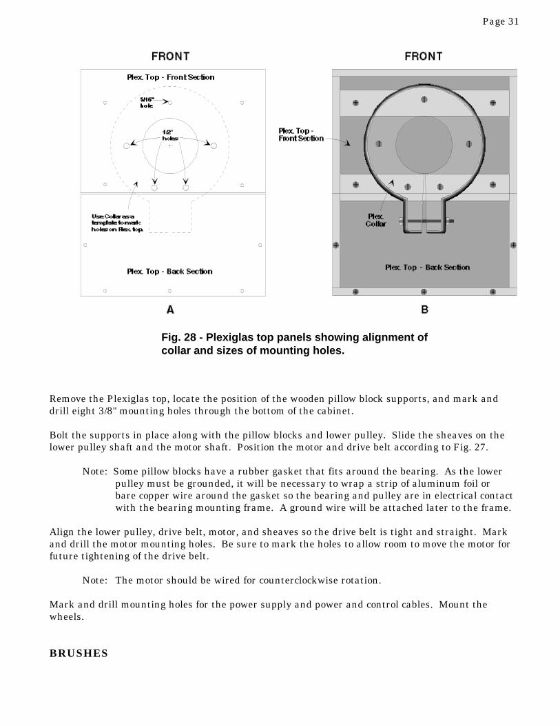
The collar holds the Plexiglas column firmly in place. It can be made from 1 1/2" thick wood,Plexiglas, or phenolic.
The router technique described earlier can be used to cut the clamp material but, because of itsthickness, the material will have to be routed from both sides. Draw an outline of the clamp on thePlexiglas, as shown in Fig. 22. Rout the outside circle first, starting at point "A" and ending at point"B." Make certain you measure to the inside of the router bit when cutting the outside circle andmeasure to the outside of the bit when cutting the inside circle.
Cut the tongue and center notch using a bandsaw (best) or jigsaw. You may find it easier to makethese cuts while the material is still square, before routing.
Drill and countersink five 5/16" holes in the collar, as shown. Make sure the countersink is deepenough that the FH bolts will fit flush with or slightly below the surface of the Plexiglas. Boltsprotruding above the surface of the collar can bleed off charge from the Collector.
For a finished appearance, rout the collar's outside edge with a 1/2" radius bit. Wet sand the edgeand any scratch marks with 120, 220, and 400 grit sandpaper. If a clear, high-gloss finish is de-sired, polish the clamp with the 7" polisher and a polishing compound like Maguire's MachineCleaner. For the highest gloss, follow up with Maguire's Plexiglas Polish.
COLUMN
The column is fabricated from a Plexiglas cylinder with a 5" O.D. and 1/4" wall thickness.
If you're fairly experienced working with Plexiglas, cutting the cylinder shouldn't be difficult. Oth-erwise, you may want to have the cylinder finished out by a plastics fabricator.
If you plan to cut the cylinder yourself, here are some tips:
When shortening the cylinder or squaring-up the ends, wrap a couple of turns of com-puter paper or lightweight poster board around the cylinder as a guide for marking a lineat a right angle to the cylinder's axis.
Use a special Plexiglas blade when using a reciprocating saw to cut the cylinder. Rub auto wax or soap on the blade to keep it from sticking to the plastic. Keep the saw
flat against the cylinder. Cut slowly and let the blade cool from time to time. Use special Plexiglas drill bits when drilling holes 1/4" and larger.
Cut the cylinder to 42" length, keeping both ends as square as possible. The top of the cylinder willneed two slots 4" long and 5/8" wide for the upper pulley shaft (Fig. 23-A&B). The shaft should fitsnugly, but should not be forced. If the slots are cut too narrow, use a file or sandpaper to widenthem. Make certain the slots are exactly 180 degrees apart.
Four brush slots will also be needed (Fig 23-C&D). All brush slots, both top and bottom, are of thesame dimensions (Fig. 23 "Insert").
Two 2 1/4" diameter holes should be cut near the bottom of the cylinder to allow insertion of the

Page 26
Fig. 23 - Plexiglas column

Page 27
Fig. 24 - Plexiglas column with belt and brushes installed

Page 28
Fig. 25 - Upper part of column. (A) Front of column showing aluminum tape,brush slot, brush, pulley, and aluminum contact strip. (B) Left side of col-umn showing brushes, pulley, connecting wires, and contact strips.
lower pulley (Fig. 23-A&B), and two bottom brush slots will added (Fig. 23-C&D). The rear brushslot is inverted and lower than the front brush slot (Fig. 23-C).
Make two aluminum Contact Strips 1 1/2" x 6 1/4" (Fig. 24-A&B). Thickness should be around 1/16"(.0625"). Drill 1/4" mounting holes in both the contact strips and the column, but do not attach the stripsuntil after the belt is installed. Countersink the holes in the column.
Apply two pieces of 2" wide aluminum tape to the inside of the column as shown in Fig. 24. Thetape will conduct charges collected by the brushes to the contact strips, and then to the Collector.
PULLEYS
The pulleys are machined from solid aluminum stock and are 2" in diameter and 3.6" long. A 1/8"taper is turned in the pulleys to help keep the belt centered. Ball bearings are pressed into the endsof the upper pulley, and these should be recessed about 1/8" to allow room for shaft collars (Fig. 26-A). The upper pulley shaft is steel 5/8" dia. and 5" long.
The lower pulley will have two 1/4" or 5/16" set screws to tighten against its shaft (Fig. 26-B). Thelower shaft is steel 14" long and 3/4" diameter.
It's a good idea to provide the machine shop with the actual bearings that will be pressed into the endsof the upper pulley (see Parts List). The shop may have aluminum and shaft material available.
BA

Page 29
Fig. 26 - Upper & lower pulleys.
Two ball bearing pillow blocks hold the lower pulley. In order to provide clearance for the sheave,the pillow blocks must be raised about 3". Cut eight pieces of 3/4" hardwood 2 1/2" x 7 1/2". Twostacks of four pieces each will be drilled and attached to the cabinet base to raise the pillow blocks(Fig. 27).
Center a pillow block on one of the pieces of wood, then mark and drill the mounting holes. Use thepiece as a template to mark and drill the remaining pieces. Clamps and a long drill bit will makethe job easier. To provide strength and stability, 3/8" bolts are recommended. Once the pieces aredrilled, give them one or two coats of varnish.
ASSEMBLY
Cut a disk of 1/2" or 3/4" wood or Plexiglas to fit snugly in the bottom of the column. This disk willstabilize the column when it is mounted in the cabinet. Drill and countersink two 1/4" holesthrough disk and bolt it to the bottom of the cabinet (Fig. 27). You should be able to easily press thecolumn on and off the disk.
Screw the plexiglas top sections onto the box and insert the column through the hole. Press thecolumn over the disk. If the alignment is off, now is the time to correct it!
If the alignment is o.k., slip the locking collar over the column. Place a strip of rubber 1/8" thickand 15 5/8" long between the column and the collar. The rubber will serve as a gasket to preventthe column from rotating and to distribute stresses from the clamp. The rubber should be about the

Page 30
Fig. 27 - Cabinet parts layout.
same height as the collar.
Align the collar with the cabinet as shown in Fig. 28. Slide a 1/4" x 5" bolt through the clamp'stongue and tighten until the column is held firmly. Mark the collar holes on the Plexiglas top.
Remove the assembly and drill one 5/16" hole in the location indicated in the Plexiglas top (Fig. 28-A). Drill all the way through the top wooden braces. Drill 1/2" holes in the positions indicated inFig. 28. These larger diameter holes will allow the mounting bolts room to move when tighteningand loosening the collar.
Page 31
Fig. 28 - Plexiglas top panels showing alignment ofcollar and sizes of mounting holes.
Remove the Plexiglas top, locate the position of the wooden pillow block supports, and mark anddrill eight 3/8" mounting holes through the bottom of the cabinet.
Bolt the supports in place along with the pillow blocks and lower pulley. Slide the sheaves on thelower pulley shaft and the motor shaft. Position the motor and drive belt according to Fig. 27.
Note: Some pillow blocks have a rubber gasket that fits around the bearing. As the lowerpulley must be grounded, it will be necessary to wrap a strip of aluminum foil orbare copper wire around the gasket so the bearing and pulley are in electrical contactwith the bearing mounting frame. A ground wire will be attached later to the frame.
Align the lower pulley, drive belt, motor, and sheaves so the drive belt is tight and straight. Markand drill the motor mounting holes. Be sure to mark the holes to allow room to move the motor forfuture tightening of the drive belt.
Note: The motor should be wired for counterclockwise rotation.
Mark and drill mounting holes for the power supply and power and control cables. Mount thewheels.
BRUSHES

Page 32
The brushes are made from clusters of copper wire crimped orsoldered into the ends of solderless terminals. The terminals arethen attached to threaded brass rod or brass bolts (Fig. 29).
The clusters of copper wire can be extracted from ordinary linecord. Strip the insulation off several inches of line cord, cut off atwo inch length of wire strands, twist one end of the cluster to-gether, and insert it into the solderless terminal. A "cluster" iscomprised of around 100-250 strands.
Upper Brushes: (Two needed) Solder a solderless terminal to a 1/4" brass nut and washer. A 1/4" x 1" FH brass bolt will screw intothe assembly from outside the column.
Lower Brushes: (Two needed) Solder a solderless terminal, brassnut, and washer to the end of a 1/4" x 2" threaded brass rod.
During soldering, alignment of nuts and washers can be main-tained by using steel nuts to hold the asssembly together. Thesolder will not sick to the steel nut, which can be removed aftersoldering. The upper brushes can be soldered while threaded on asteel bolt. When removed from the steel bolt, the assembly will beperfectly aligned. The brushes will be trimmed and adjustedduring final assembly of the components.
HIGH VOLTAGE POWER SUPPLY
Any DC source providing 10 kV to 15 kV will work. The currentrequired is virtually nil (6-10 microamps), so almost any sourcewill do. Oddly enough, I found a slight increase in performance if
the current capacity of the power supply is at least 1 mA. I can't explain this, because the currentdemand, including leakage, is only around 5 microamps, max.
An inexpensive, "gorilla proof" supply is described below. The transformer and rectifiers can with-stand short circuits and can provide more than 15,000 volts of either polarity. For safety, currentlimiting resistors are placed in series with the output.
The transformer specified is a 6.5 kV "core and coil" unit manufactured by Actown Electrocoil, Inc..The company manufactures top-quality transformers and sells factory-direct, so the price is low.Output from the transformer is doubled to approximately 15 kV with a simple voltage multiplier.
One leg of the transformer's output is grounded, and although this is not a standard practice in theneon sign business, the technique works for this low-current power supply.
To reduce shock hazard, a 1 to 2 megohm, 6 W resistance is placed in the ground leg. A direct shortcircuit will burn this resistor out, so make certain that the power supply wiring is correctly spacedand the lower brushes are far enough from the pulley that sparks cannot jump. A bleeder resitoracross the voltage doubler isn't really needed, although the capacitors store enough of a charge foran irritating shock if you come between the output and ground. Always unplug the generator and
Fig. 29 - Brushes

Page 33
Fig. 30 - High voltage power supply. (A) Schematic (B) Pictorial
short out the capacitors when working inside the unit.
The Collector will develop the same polarity as the power supply's output. Before deciding whichpolarity to use, you might want to review "Experiments," p. 40.
CHARGING BELT
The charging belt is made of gum rubber 1/8" thick, with an inside circumference (or "IC") of 68".Although the belt will have to be custom made, the cost will be fairly low...around $20.00. A sup-plier is listed in the Appendix.
Installing the Charging Belt: Place two 5/8" shaft collars on the upper pulley shaft. Adjust theshaft and collars so the pulley is centered in the column and the shaft is even with the outside of thecolumn. If the shaft protrudes slightly past the column, file it off until it's flush. Apply a drop ofLoctite to the threads of the collars' set screws and tighten. Set the upper pulley aside.
Remove the lower pulley. Tie a 1/2" or 3/4" nylon rope around the charging belt and lower the beltthrough the top of the column (touch the belt as little as possible). You may find the task easier ifyou lay the column on the floor or across a bed, keeping it fairly horizontal.
B
A

Page 34
Insert the lower pulley through the columnand through the charging belt (Fig. 31). Pullthe free end of the belt up through the top ofthe column and carefully insert the upperpulley through the belt. (This operation willrequire two people, one to pull the rope andone to push the upper pulley under the belt).
Lower the pulley, placing the shaft into theslots. Untie the rope and pull it from the belt.Straighten the belt so it's even.
Installing the Column: Slide the column ontothe disk mounted inside the cabinet and alignthe column. Place the pillow blocks on the lowerpulley shaft and loosely bolt the assembly inplace on the wooden supports (Fig. 32).
Note: Make certain that the pillowblocks' bearings make electrical con-tact with the pillow block frame. If arubber gasket surrounds the bearing,wrap some aluminum foil or barecopper wire around the gasket.
Align the assembly and begin tightening themounting bolts. Center the belt on bothpulleys and rotate it a few times by hand.Once a reasonable alignment is achieved,tighten the mounting bolts.
Attach the Plexiglas top and locking collar,and align and tighten the entire assembly.
Installing the Motor: Place the V-belt onthe lower pulley and motor sheaves. Bolt themotor in place and temporarily wire the motorso it can be run to test the alignment. ApplyLoctite to the sheave threads before final tightening.
After the assembly is aligned and tested by hand, switch the motor on briefly and check for beltwandering or vibration. If the charging belt wanders, check to see that the pillow blocks are tight,that the front-to-rear alignment of the column is correct (twisting the belt can make it wander), andthat the pulleys are parallel. If the overall alignment is fairly close, the wandering belt can nor-mally be fixed by placing shims under the pillow blocks.
Once the belt is balanced, it usually stays that way. (Surprisingly, a balanced belt can sometimes
Fig. 31 - Belt installation requires stretchingthe belt using a rope.

Page 35
be thrown slightly off when the charging circuit is turned on. The electrostatic charge on the insideof the column is apparently strong enough to sometimes pull the belt off center!)
Install the two aluminum contact strips shown in Fig. 24-A&B.
Be especially careful when installing hardware on the column. A nut or bolt dropped inside thecolumn will be difficult to extract, and may necessitate removing the entire column.
Installing the Upper Brushes: The front upper brush should lightly contact the belt. Screw thebrush/nut/washer/ combination onto the 1" FH brass bolt and insert the assembly into the upperbrush slot, fitting the bolt into the countersunk hole. Tighten the assembly and check the length ofthe copper wires.
If the wires need to be trimmed, remove the assembly and cut the wires as evenly as possible,forming a fan shape that spans the width of the charging belt, as shown in the drawings. Reinstallthe assembly and check the fit. The wires should lightly touch the belt. You may find it helpful touse a screwdriver to bend and adjust the wires.
Repeat the procedure to install the rear upper brush, but space the brush about 1/8" away from thebelt. The rear brush should line up approximately with the front brush.
Installing the Lower Brushes: The front lower brush should line up as closely as possible withthe area where the charging belt separates from the lower pulley as the belt travels upward. (Fig.24-C&D). When the belt is moving, this area will sometimes shift slightly downward, as the cen-trifugal force tends to pull the belt away. The brush should be spaced about 1/8" away from the belt,but not so close as to allow sparks to jump to the pulley when the power supply is turned on. Trim-ming the brush wires for a perfect fit may be a bit tedious, but essential for high performance.
The lower rear brush should be positioned as shown in Fig. 24-C. The brush should be around 1/8"from the pulley. Both the front and rear brushes will be connected to the power supply, so the rearbrush must also be adjusted so no sparks will jump between it and the pulley.
Installing the Power Supply: The core & coil transformer can be screwed directly to the cabinetbase or mounted in an aluminum box. Mount the voltage multiplier on the side of the cabinet nearthe transformer (Fig. 27). Use nylon bolts and spacers to keep the multiplier about an inch awayfrom the cabinet side. Keep all wiring and conducting materials at least two inches from the multi-plier.
WIRING
Twist wires around each end of the upper pulley shaft and run them inside the column to the alumi-num contact strips, as shown in Fig. 33-A. If you can't wrap the wires around the shaft, wrap themaround the shaft collar (the shaft doesn't rotate...only the pulley). Any convenient wire size willwork, but #16 or #14 will probably be easiest. Route the wires away from moving parts, and makesure they can't vibrate out of position.
Connect a jumper wire between the front and rear lower brushes (Fig. 33-B). Well-insulated hookup

Page 36
wire will work, but 15 kV neon sign wire is preferred.
Run a length of 15 kV neon sign wire between the voltage multiplier output and the front lowerbrush. This wire should be routed clear of all other wiring and conductors.
Connect a ground wire between one of the pillow block bolts and the 5/16" brass ground lug installedin the rear of the cabinet. This wire must ground the lower pulley, so make certain that no rubbergasket material insulates it from the pillow block bearing.
Install the fuse and terminal strip, and bring in the a.c. power and control cables. The cables can besecured with nylon wire stays and straps.
The remote switch box wiring is straightforward. You can bring the control cable into the box anduse a strain relief or, for a deluxe version, you can install a military type connector that will allowyou to disconnect the box (see Parts List). If you want to ground the box, you'll need to use a four-
Fig. 32 - Parts Layout

Page 37
conductor control cable instead of the three-conductor specified. The control cable can be just aboutany length, but 8' to 15' fulfills most requirements.
TESTING
Connect the ground lug to an earth ground and attach a hand-held electrode to the ground lug (see"Experiments" for details on building and using a hand-held electrode).
Leave the collector off. Turn the motor "on," then the power supply. The aluminum contact stripsshould immediately charge and make a crackling sound. You should be able to draw a steadystream of 1/2" to 1" sparks between the strips and the hand-held electrode. No sparking shouldoccur at the lower brushes, and the belt should run true.
Place the Collector over the column and level it by eye. Turn the generator on again. The Collectorshould start making a crackling sound in 3-5 seconds, indicating full charge. Bring the hand-heldelectrode close to the Collector. Fat, noisy sparks 3" to 4" long should jump to the electrode. Whenpulled farther away, the electrode should draw thinner sparks 12" to 18" long, depending uponconditions.
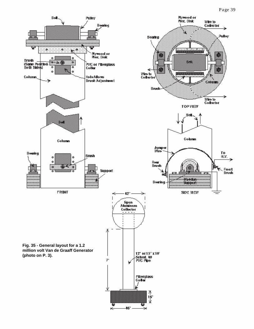
General layout for a 1.2 million volt Van de Graaff Generator (photo on P. 3) is shown in Fig. 35.
Fig. 33 - (A) Wiring from upper pulley to contact strips. (B) High voltagewiring to lower brushes.
A B

Page 38
Fig. 34 - Completed 4' Van de Graaff Generator. (A) Rear view (B) Front (C) Front panel removed, showingbearings, wooden supports, and a front brush made from brass screen. (D) Rear view showing motor and aH.V. power supply circuit described on P. 14.
A B
DC
This generator is very similar to the 4' model. The top half of the Collector is removable, so theupper bearings are mounted outside the column, allowing for a slightly larger belt width. The powersupply consists of a 15,000 volt neon sign transformer with the center tap grounded and the highvoltage taken from one leg (see Fig. 11, P. 12). The brushes are made of brass screen, and placementis identical to the 4' model, except that none of the brushes touches the belt; they're positioned about1/8" away from the belt.
The cabinet is Formica over plywood. Front, rear, and top panels are removable. Motor is a onehorsepower, 1,725 r.p.m., split phase, turning the charging belt at about 1 1/4 revolutions per sec-ond. Sparking distance to a 12" grounded sphere is around 48", sometimes longer.
EXPERIMENTS
Page 39
Fig. 35 - General layout for a 1.2million volt Van de Graaff Generator(photo on P. 3).

Page 40
1. Free-Air Discharge: Good conditions and a very dark room are required to properly observefree-air discharge phenomena. Allow time for your eyes to adjust to the dark.
A positive Collector produces a very interesting discharge: a violet-colored streamer about 8" to12" long will dart from the Collector and terminate in a beautiful fan shape. A faint, muffled"snap" accompanies this discharge. When conditions are good, the generator will produce one ofthese streamers every few seconds.
A negative Collector tends to produce fewer air discharges and, when they occur, they are moreconcentrated and tend to form a more common lightning-like form, with minimal branching.
2. Discharge to a Hand-Held Electrode: Drawing long sparks takes the right configuration anda bit of practice. Under good conditions, the 4' Van de Graaf can produce visible sparks morethan 12" long between the Collector and the proper ground electrode (Fig. 36).
Large diameter electrodes work better than small ones. For maximum spark length, use adischarge electrode 8" to 12" in diameter. It's essential that the electrode's surface be smooth.Attach a small acorn nut or small diameter brass ball "bullet" to one side of the electrode, asshown. The nut or ball serves as a "discharge initiator, assisting in the formation of sparks.
Stand about three feet from the Collector. Make sure your clothing is free of sharp conductors(pins, watch, etc.), and keep your free hand by your side.
Turn the generator on and slowly bring the electrode close to the Collector, presenting thesmooth side of the electrode. A fat, loud spark will jump about three or four inches to the elec-trode. Pull the electrode back and rotate it so the "initiator" faces the Collector. With a littlepractice, you can draw sparks 8" to over 12" long from the collector. The electrostatic charge
Fig. 36 - Drawing sparks with a hand-held electrode

Page 41
Fig. 37 - "Hair Raiser"
exerts a noticeable force on the electrode, tugging at it as the charge builds up. The long sparksare quite dim and can be seen only in subdued lighting. However, they make a quite audible"snap" as they strike.
Hold the electrode approximately 18" away. Occasionally, you will see very faint, relatively fatstreamers discharge between the electrode and the Collector. These streamers seem to havedistinct segments, or portions. The main channel is perhaps two or three inches in diameter.There is sometimes a dark band near one end, and sometimes slightly brighter blue-white stria-tions appear throughout the discharge. The streamers are so faint that nearly total darkness isrequired to see them.
3. "Hair Raiser": For young audiences, this is undoubtedly the most entertaining demonstrationVan de Graaff Generators provide. Place a plastic (not wood or metal) step or stool 10" to 12"tall beside the generator. Choose a "victim" with medium long, loose hair...the finer and drierthe hair, the better. Have the person stand on the stool, keep his/her free hand by her side, andplace her other hand flat on the Collector (Fig. 37).
Make sure the individual is not wearing a sharp-pointed, conducting object, like a hair pin.Instruct the individual to keep her hand on the Collector, as she can receive a mild shock if herhand is lifted. Stand back five or six feet and turn the generator on.

Page 42
Fig. 38 - Electric Spinner
In a few moments, her hair should begin to rise. If her hair becomes tangled and stubborn, haveher shake her head a few times to loosen it. The demonstration works best if the "victim" is tallenough that her head is above the Collector. When the demonstration is finished, bleed thecharge from the individual by bringing a sharp-pointed, grounded wire slowly toward her.
The "Hair Raiser" demonstrates the principle that like charges repel.
4. Lightning Rod: This demonstration shows how Benjamin Franklin's lightning rod works.Turn the generator on and bring a sharp-pointed conductor slowly toward the Collector. Thepoint will make a hissing sound as it approaches the Collector. In darkness, you'll be able to seea faint corona..."Saint Elmo's Fire"...glowing at the point. No sparks will jump to the conductorbecause the sharp point bleeds the charge off before it has a chance build up.
The effect can be dramatized further by taping several lightweight ribbons or lengths of threadto the Collector's top. The ribbons will stand out as the Collector becomes charged and willdroop as charge is bled off. Try using some of the very lightweight, colorful, twine used for tyinggifts. Attach five or six strands about 10" long.
5. Recalcitrant Styrofoam: Have another "victim" stand on the insulated platform. Have himplace one hand on the Collector, and in the other have him hold up a styrofoam cup. Fill the cupwith styrofoam excelsior (the hemispherical kind works best). Turn the generator on. Thestyrofoam will jump out of the cup, sailing several feet. The foam sometimes sticks to otherobjects before losing its charge and dropping off.
6. Orbiting Satellites: Cut several small pieces of aluminum foil into narrow triangular shapeswith tabs at the base. Twist the tabs in opposite directions, so that if the foil were dropped, itwould tend to rotate. Make the triangles about 3/4" to 1" long. Place the triangles on top of theCollector and turn the generator on. The foil triangles will jump off and "orbit" the Collectorbelow the seam, hitting the Collector from time to time.

Page 43
Fig. 39 - Leyden Jar
The trick is to get the foil shape and size just right, so the foil spends as much time as possiblein the air.
7. Electric Spinner: A pinwheel made from lightweight aluminum will spin slowly when placedatop the Collector (Fig. 38). Theoretically, the sharp points form ions, which are repelled. Thereaction causes the spinner to rotate.
8. Lightning in a Bottle: Caution! This experiment can cause a shock. A Leyden Jar is a capaci-tor and can store a powerful charge. The jar was invented (partly by accident!) by Pieter vonMusschenbroek in Leyden, Holland in the 1700's.
The larger the Leyden Jar, the greater the charge it will hold. You can make as large a jar asyou wish, or wire a number of them in parallel, but keep in mind that, if enough capacitance isused, a lethal charge can be stored (See section on safety). I suggest using a relatively small jar,approximately a pint, as shown in Fig. 39.
Hold a ground wire against the outside foil of the jar and hold the center electrode close to theCollector. After about 10 seconds, remove the jar and set it on a table. Use the shorting bar todischarge the capacitor. The spark will be short but quite loud. The jar will also cause a fluores-cent or neon lamp to flash brightly. Use high voltage wire to make the connections.
9. Versorium: The Versorium was one of the first electrical instruments. It's simply a metal rodpivoted on a needle so it can rotate freely. Use a lightweight copper or brass tube about sixinches long. Drill a hole at the balance point, punch an indentation in the tube, and insert asharpened nail or needle. The nail can be mounted on a Plexiglas base. Hold the Versoriumnear the generator, and one end will be attracted to the Collector. Hold a charged Leyden jar

Page 44
Fig. 40 - Smog Eater
near the Versorium and make it rotate by moving the jar in a circle.
10. Smog Eater: You can demonstrate the principle of electrostatic precipitation with the "SmogEater." Take a large glass or plastic container and insert a metal rod with copper wire "whis-kers" (Fig. 40). Glue a strip of aluminum foil to the inside of the jar and run a ground wirethrough the jar to the foil, as shown. Introduce smoke from a cigarette (sorry!) or some othersource through the plastic tube. Connect a wire between the Collector and the rod, or simplybring the jar close to the Collector. Turn on the generator and, voilá, the smoke disappears. Therod charges the smoke molecules, which are repelled from the rod and deposited on the alumi-num foil.
11. Electrostatic Motor: Two variations of electrostatic motors are shown in Fig. 41. The DiskMotor is relatively complex, but offers higher performance than the simpler "Pop Bottle" motor.
The Pop Bottle motor will rotate at around 200 rpm. Properly adjusted, and under the rightconditions, the disk motor can achieve better than 500 rpm. For publications offering moreinformation about electrostatic motors, see the Appendix.
The key to performance is low-friction; the spindles must be fitted to allow very free rotation ofthe disk or pop bottle. There should be about a 1/8" gap between the brushes and the foil seg-ments. Wiring should minimize electrostatic leakage.
12. High-Voltage Human: You can preserve a charge on yourself by donning rubber boots and aplastic raincoat. Eliminate metal objects. Expose as little skin to the air as possible. Stand onthe insulated platform and charge yourself up. When you step down, your boots will crackle asyou walk. If you touch someone...you know the rest. Be careful, you can startle your victims;and don't even think about coming close to a computer!
13. Charging with Ions: Attach a short wire to the Collector and point it toward an individualstanding on the insulated platform. The person will become charged even if he's several feetaway. The charge from the Collector creates ions at the sharp ends of the wire. The ions driftthrough the air and are initially attracted to the person's body.
14. Charging by Induction: Place the insulated platform about four feet from the generator.

Page 45
Fig. 41 - Electrostatic Motors

Page 46
Have someone stand on it and turn on the generator. While keeping yourself away from theCollector and the individual, bring a grounded rod in contact with the person. Remove theground and turn off the generator. Touch the individual with one input wire from a DCmicroammeter or a neon lamp (lamp and microammeter have one wire grounded). The personwill have a charge, which will discharge to ground through the meter or lamp. The person'scharge will be opposite that of the Collector. (The electrode of the neon lamp that glows is theone receiving the negative charge.)
TROUBLESHOOTING
1. Belt Wanders: If the belt wanders to the right, for instance, add washers under the leftpillow block until the belt runs true.
If the pulleys are properly tapered and reasonably well aligned, the belt will stay centered. Thebelt itself must be accurately made. If it is very uneven, it will wander and vibrate.
2. Sparking Between the Lower Brushes and Pulley: Move the brushes back until thesparking stops. Sparking should not be a problem with the power supply specified, but if itpersists, the output voltage of the power supply must be reduced. The simplest way to reducevoltage is to remove the multiplier and use the transformer in a simple half-wave rectifiercircuit.
A 10-watt potentiometer can be wired in the primary of the transformer for broad voltage con-trol, but remember that a short circuit could quickly destroy it.
3. Low Collector Voltage:
• Collector and column must be free of dust, lint, fingerprints, and moisture.• Belt must be clean and dry.• Brushes must be correctly aligned (best alignment is experimentally determined).• No sharp conductors should be nearby.• Collector should be smooth, without sharp metal seams or gouges.• Power supply must produce enough voltage (10,000-15,000 V).• Humidity must be fairly low (using a hair-dryer on the column and belt may help when the
humidity is very high).• Lower pulley must be at ground potential. Any rubber gasket existing between the bearing
and its frame should be wrapped with a strip of aluminum foil or a piece of bare copper wireto maintain electrical contact with the ground wire.
• Brushes must be in their proper positions.• Belt must rotate in the proper direction; forward-facing part of belt travels upward.
SAFETY
The high-voltage power supply can produce a serious shock. Always unplug the generator anddischarge the capacitors before working inside the cabinet.
The electrostatic charge that resides on the Collector is generally consideded safe for human con-tact. Exceptions may include individuals wearing heart pacemakers. Keep in mind that although ashock from the generator's Collector is not sufficient to cause injury, the shock can startle.

Page 47
The generator can charge capacitors, such as Leyden Jars. If a sufficient charge is stored in a largeLeyden Jar or other capacitor, a dangerous, or even fatal, shock could occur. How big a Leyden Jaris considered safe? A pint-sized jar can deliver an uncomfortable shock. A gallon-size would bepainful. Although studies have been conducted to determine approximate energy levels that can besafely taken by the body, the author makes no claim regarding safety limits. Just exercise greatcaution when storing a charge in any capacitor.
Static electricity from the generator can be damaging to computers and sensitive microprocessors.Keep the generator away from electronic equipment, including diskettes, videotapes, and othermagnetic media.
Keep in mind that you can carry a computer-damaging charge on your body for several minutes. Besure to ground yourself before using a computer.
APPENDIX
Components for 4' Van de Graaff Generator
1. Collector: 12" or 14" diameter aluminum sphere. Source: W.F. Norman Corp., 214-32N. Cedar Street, Nevada, MO 64772-0323 (800) 641-2708.
2. Column: 5" diameter x 42" long x 1/4" wall Plexiglas tube3. Belt: 3 1/8" wide x 68" inside circumference x 1/8" thick gum rubber. Source: Texas Rubber
Supply, Inc. P.O. Box 565067, Dallas, TX 75356-5067 (214) 631-3651. Ask for the Belt Division.4. Motor: 1/6 hp., 1725 rpm, split phase Dayton or equivalent (W.W. Grainger stock # 6k551).
Note: W.W. Grainger is world wide. To find the store nearest you, check Yellow Pages or call(214) 637-2380.
5. Upper pulley: See PP. 28 & 29.6. Lower Pulley: See PP. 28 & 29.7. Upper Bearings: Upper pulley bearings should be ball bearings for a shaft diameter of 5/8"
(Fafnir S7KDD or equivalent; W.W. Grainger stock # 1L006).8. Pillow Blocks: Self-aligning, light duty ball bearing (W.W. Grainger stock #2X899).9. Motor sheave: 2" OD, 1/2" bore (W.W. Grainger stock # 3X760)10. Pulley sheave: 2.8" OD, 3/4" bore (W.W. Grainger # 3X771)11. V-belt for motor: See P. 34. Best way to determine proper size is to wrap a 1/2" nylon rope
around the sheaves with the motor in its proper location. The rope will give the circumference ofthe v-belt.
12. Power supply: • Transformer• Rectifiers• Capacitors• Resistor(s)• PC board or Plexiglas• Nylon bolts & spacers
13. Fuse: 5 A. slow-blow14. Two S.P.S.T. 10 A. toggle switches15. Switch box: Radio Shack or, for a deluxe version, a cast aluminum Bud Econobox type
CU-234 (Available through Allied Electronics (800) 433-5700).16. Power cable: Three conductor #16 or #18.
17. Control cable: Three conductor #16 or #18

Page 48
18. High voltage wire: 15 kV neon sign wire.19. Contact strips: Cut from 1/16" (.0625) aluminum sheet20. Locking collar: Cut from 1 1/4" Plexiglas or phenolic21. Top panels: Cut from 1/4" Plexiglas22. Casters: Four 2" dia., swiveling (at least two should lock)23. Cabinet: 3/4" cabinet-grade plywood. Can be covered with Formica.24. Terminal strip: Available through Allied Electronics and most electrical supply stores.25. Upper brushes: Made with F.H. brass screws, solderless terminals, copper wire "whiskers,"
and brass nuts & washers.26. Lower brushes: Made with 1/4" threaded brass rod, solderless terminals, copper wire
"whiskers," and brass nuts & washers.27. Connectors: Optional military style connectors for control box. Allied Electronics has
several styles to choose from.
BOOKS & LITERATURE
Dibner, Bern. Early Electrical Machines. The Burndy Library, Norwalk, CT, 1957. This book is filled withinteresting history, woodcuts, photos, and drawings of electrostatic machines dating from pre-Von Guericketo Wimshurst.
Ford, R.A. Homemade Lightning, Creative Experiments in Electricity. TAB Books, Blue Ridge Summit, PA,1991. An excellent "how-to" book concerned mainly with the construction of a sectorless Wimshurst ma-chine. The author, R.A. Ford, developed a high performance model that can produce a substantial spark upto 10" in length. Considering the size of the machine (disks are only 14" in diameter), I'd say it rivals a goodVan de Graaff in performance! Book also contains much additional material and many sources for parts andinformation.
Scientific American. "Possibilities of Electro-Static Generators." March, 1934. An interesting article byNikola Tesla, who analyzes the new electrostatic generator built by Van de Graaff. Tesla computes thevoltage, charge, energy, etc. of the machine and elaborates on its uses as an "atom smasher." Unfortunately,Tesla exposes his ignorance of the new atomic physics, thinking of atoms as basically inert, with little possi-bility of anything useful coming from their being smashed.
Scientific American. Title unknown. 1952 (?). This article can be found through the Reader's Guide toPeriodical Literature under the heading, "Van de Graaff Generators." The article gives generalized plansand parameters for both friction and externally-excited machines.
Popular Electronics. "200,000 Volt Van de Graaff Generator." October, 1990. Article shows construction of asmall friction machine and includes several experiments.
National Geographic. "Lightning, Nature's High-Voltage Spectacle." July, 1993. Great shots of natural andman-made lightning. Includes excellent photo of a large Van de Graaff Generator at the Boston Museum ofScience, as well as several interesting Tesla Coil discharges.
Van de Graaff Generator Parts & Kits
Two Van de Graaff Generator kits (assembled available also) are offered by SCIENCE FIRST, 95 BotsfordPlace, Buffalo, NY 14216-2696 (716) 874-0133. The company offers generators with a 14" and a 7" Collector.Both machines are friction excited, which means, of course, that they are very susceptible to humidity.However, the generators are very inexpensive and should be perfect for the experimenter who hasn't thetime or resources to build an externally-excited machine.