Embed Size (px)
Citation preview

IN COMPLIANCE WITH MACHINERY DIRECTIVE 98/37/EC
COMPLETE WITH DECLARATION OF CONFORMITY,
MAINTENANCE
RECORD AND SYSTEM COMPONENTS
DIAGRAM TO BE FILLED IN AND GIVEN
TO THE END USER
GB2003
PROCEDURES FOR AUTOMATICGATES AND BARRIERS IN CONFORMITY WITHEN 12453 AND EN 12445 SAFETY STANDARDS
GUIDE TO INSTALLATION

2
Meccanica Fadini has compiled this guide in order to provide the installer and all professional figures working in the sector of automatedcivil and industrial entrance systems with a summary of the essential guidelines for the installation of automatic gates, starting withrisk analysis and resolution in keeping with EN 12455 and EN 12453 safety standards, within Machinery Directive 98/37/EC.All contents of this guide must be strictly adhered to when installing or checking automatic entrances.The manufacturer does not guarantee installations performed using methods and procedures not described in this booklet, and declinesall responsibility for consequent damage to persons, animals and material goods.
GENERAL INFORMATIONAs in most sectors today, the installation and motorization of an automatic gate or entrance is supported and governed by countlessregulations and laws, primarily in terms of safety for both the installer and the end user.For years, the UNI 8612 standard in force until May 2001 was used as a reference by all professional figures working in the automaticgate sector for the correct installation and construction of a power operated gate.Today, UNI 8612 has been replaced by the EN 12445, EN 12453, EN 12604 and EN 12605 standards, etc. These standards indicate theinstaller as the appropriate professional figure for installing the gate and testing the whole system in order to ensure that it complieswith safety standards and is in good working order.According to the current Machinery Directive 98/37/EC, all automated barriers are effectively “machines”, therefore it raises the problemof barrier safety through a typical machine approach.
According to the standards, anyone who sells and installs a power operated gate or entrance becomes the “constructor” and is“responsible” towards the end user of the “machine/automatic gate”. This responsibility entails compiling and conserving (for at leastten years following the installation date) the system’s Technical File, which should include such documentation as a complete poweroperated system design, a list of all the components, the Electrical Diagram (provided in the Installation Guide), the Installation andUser Guide, the Maintenance Record, the Declaration of Conformity and the Risk Analysis: this will be explained in greater detail laterin order to assist the installer in his/her work.
What must an installer do? He/she must firstly assess the suitability of the gate to be automated, install the system following principlesof good practice in order to ensure the system’s correct working order, test the system and then compile the Technical File: carry outthe risk analysis, include a copy of the Declaration of Conformity, draw up the electrical diagram, list all the system components, fill inthe Maintenance Record and apply the CE plaque to the automated entrance.What should be consigned to the end user? At the end of this safety procedure, the end user must be provided with the installed system’sUser Manual, Maintenance Record and Declaration of Conformity; the end user is thus responsible for the correct use of the entireautomated system.
The EN 12445 and EN 12453 safety standards specify methods and components for ensuring the safety of automatic entrances, proposingmethods for the reduction or complete removal of probable risks to people found during the risk analysis, which must be carried outby all installers.However, while these standards are strict and detailed, they leave the installer with the possibility to interpret them in keeping with aprofessionally performed installation, with all the minimum safety accessories required by the Fadini range.
Technical TerminologyRisk Analysis = List of risks in an automatic system (mechanical, electric, electromagnetic, etc.) and finding the most suitable solutionsfor removing the various risk situations.Main Edge = Automatic gate surface that poses a possible risk while the system is in operation.Sensitive Edge = This indicates an electromechanical or electro-pneumatic type device or an electromagnetic plate to be applied tothe Main Edge or in zones that present a risk of entrapment, thereby making it possible to interrupt or invert the gate’s movement.Operator command = This indicates a command in order to make the gate move in a “controlled” fashion (without relay self-holdingfunction), thereby implying the active presence of the operator throughout the gate’s progress until the button or switch key is released.EN 12445 = Safety standard indicating test and classification methods for safety devices.EN 12453 = Safety standard obtained through the risk analysis and successive risk elimination or reduction operation.EN 12635 = Standard regulating installation, maintenance and repair procedures and parameters.EN 12987 = Standard that defines the characteristics of pressure sensitive protective equipment (PSPE) such as plates and sensitiveedges, while photocells, capacitive sensors and electro-sensitive sensors are in the ESPE category.Technical File = Technical documentation encompassing (in compliance with Attachment V of the MD):
- Complete automatic entrance design - Electrical diagram- Risk analysis encompassing the entire installation - Installation Booklet- User Instructions and General Safety Warnings - Compiled Maintenance Record- EC Declaration of Conformity- Compiled CE plaque attached to the automatic gate.
Risk = The overall probability that a dangerous situation may arise.Dangerous Zone = Area in the vicinity of the power operated system that poses a risk to the health and safety of persons or materialgoods.

3
MAIN EDGE PROTECTIONThe main closing or opening edge is simply the gate’s profile that may pose a danger or physical risk to people while in movement. Itmust therefore be made “safe”. The following table summarizes the figures able to control the movement of the gate with respect tothe type of installation.The table should be understood as a minimum level of protection and must be referred to when compiling the Risk Analysis.
1) Expert personnel working in a private area: authorized personnel within a company2) Authorized personnel in an area facing onto a public street3) Any personnel working in an area facing onto a public street
N.B: If an automatic gate’s movement is controlled by the operator command, the presence of photocells or a sensitive edge is sufficientin order to ensure that the system is safe, without the need for measuring the forces in play.
MAINTENANCE:In order to ensure a long working life it is very important to keep all automatic gate components in a good state of maintenance, sincethis makes it possible to prevent, and therefore reduce, any avoidable faults or repairs; saving money and end user disappointment.Therefore, the Directive requires the maintenance and inspection operations to be scheduled by the installation company and the finaluser, in relation to the provisions suggested by this document in the Maintenance Record.
APPLICABLE STANDARDS:A list follows of all applicable European and Italian standards:EN 349 - Indicates minimum safety distances in order to prevent body parts being crushedPR EN 12453 - Safety and use requirements and classifications for industrial, commercial and residential gates and doorsPR EN 12445 - Safety and use test methods for industrial, commercial and residential gates and doorsPR EN 12604 - Requirements and classifications for industrial, commercial and residential gates and doors - mechanical aspectsPR EN 12605 - Test methods for industrial, commercial and residential gates and doors – mechanical aspectsPR EN 12635 - Procedures for safe installation and use of industrial, commercial and residential gates and doorsPR EN 12650-1 - Accessories for doors and windowsEN 12987 - Standard defining the characteristics of pressure sensitive protective equipment (PSPE) such as plates and sensitive
edges, while photocells, capacitative sensors and electro-sensitive sensors are in the ESPE category.EN 60204-1 - General regulations regarding the safety of the system’s machinery and electrical equipmentEN 60335-1 - General regulations regarding the safety of the system’s machinery and electrical equipmentUNI 8612 - Power operated gates and entrances – Construction criteria and accident prevention devicesCEI 64-8 - Electric plants not exceeding 1˙000 V in AC and 1˙500 V in DCOther Standards: .............
Type of Command
Operator Command
Impulse commandwith gate in sight
Impulse commandwith gate OUT of sight
Automatic command(i.e. timed closure)
Employment
1) Expert personnel inprivate area
2) Expert personnel inpublic area
3) Any personnel inpublic area
Sustained action command
Force reduction, orphysical presence sensors
Force reduction or physicalpresence sensors
Force reduction andphotocells, or physical presencesensors
Sustained action keycommand
Force reduction,or physical presencesensors
Force reduction and photocells,or physical presence sensors
Force reduction and photocells,or physical presence sensors
The Operator command is NOTpossible
Force reduction and photocells,or physical presence sensors
Force reduction and photocells,or physical presence sensors
Force reduction and photocells,or physical presence sensors

4
TO BE ENCLOSED IN THE TECHNICAL FILE AND A COPY GIVEN TO THE END USERDECLARATION OF CONFORMITYThis document must be filled in and enclosed in the Technical File and a copy given to the client (we recommend making a copy of theoriginal, in reference to Machinery Directive 98/37/EC – Enclosure 2 – Part AThe Declaration must include the name and address of the system manufacturer and installer, a product description, the requirementsthat the product conforms to and the name and position of the person authorized to sign the declaration on the manufacturer’s behalf.The Declaration of Conformity certifies that the automatic system meets all requirements in the aforementioned standards. It is thereforevalid for installations consisting of Fadini products and accessories and for all compliant authorized interventions which respect theprinciples for which the installation was designed and tested, while improper use of the system by the end user voids this documentand the objective responsibility of the installer/constructor.
DECLARATION OF CONFORMITY-Machinery Directive 98/37/EC, Enclosure 2, part A
Constructor/Installer
Constructor/Installer Address
Declares that (system description and type)
System Address
Conforms to Machinery Directive 98/37/EC
Conforms to Electromagnetic Compatibility Directive EMC 89/336/EEC and 93/68/EC
Conforms to Low Voltage Directive LV 73/23/EEC and 93/68/EC
Conforms to Radio and Telecommunication Terminal Equipment Directive R&TTE 99/05/EC
Harmonized Standard EN 12453 – Power operated gate requirements – has been applied
Harmonized standard EN 12445 – Power operated gate test methods – has been applied
………….
The following national standards and technical specifications have been applied
CEI 64-8 Electrical plants not exceeding 1˙000 V in AC and 1˙500 V in DC
....
Date Signature of legally responsible person
CONFORMITY PLAQUE – TO BE INSTALLED IN A VISIBLE POSITION ON THE GATEThe mark that attests that the system has been installed in full respect of the safety standards is certified through the plaque to beattached to the gate, complete with the information as described in Enclosure I of the Machinery Directive:- Name of Manufacturer or Installer and address- CE Mark- Designation of Series No. and Type- Year of Construction- Technical information such as weight and speed
This manual provides instructions on how to apply the Directive. The company assumes no responsibility for any errors or damage to people or things.
RETAIL OUTLET
Via Mantova,177/A37053 Cerea (VR)Italy
No.FAB. Year REG. N.m. m/s.Weight kg. Type
!®
AUTOMATIC GATE
GATE AUTOMATION FACTORY
®
the gate opener

5
A -Impact B -Crushing C -Shearing D -Entrapment E -Cuts F -Hooking
SLIDING INSTALLATION – TO BE ENCLOSED IN THE TECHNICAL FILE
RISK ANALYSIS AND SOLUTIONS ADOPTEDEvery automatic gate must be complete with an analysis of the possible risks to people, therefore a table follows below that shouldbe filled in (after having made a copy of the original) with the main mechanical risks found and relative solutions to be adopted (numberednext to the table) in the most hazardous points listed in Pic. 1.
UNAVOIDABLE RISKSIn the mechanical risk analysis, not all hazards found are avoidable, therefore the EN 12445 and EN 12453 standards make provisionsfor written warnings, both in the Risk Analysis and above all on the hazardous points of the system itself that cannot be protected. Thesesigns should be standard danger signs in black on a yellow background (i.e. protruding handles or doors, or excessive steps or risesin the ground), while for forbidden zones the prohibition and danger signs provided for by the highway code should be used.
Main mechanical risks to look out for in the system’s danger zones
A - Impact and CrushingB - Impact and CrushingC - ShearingD - Entrapped handsE - Entrapped feetF - Entrapped hands
If the gate surface is not closed,we recommend installing a protectivemesh in order to cover the entiresurface of the sliding gate.
List of main danger points in a moving sliding gate.PIC. 1
Solutions Adopted:
1 - OPERATOR COMMAND2 - FORCE REDUCTION3 - SENSITIVE EDGES OR RIBS4 - PHOTOCELLS5 - SENSITIVE PLATES6 - VISUAL WARNING SIGNS7 - ACOUSTIC WARNINGS8 - COVER9 - other
Installation Type Client: Address:
Date:
Instal lat ion Firm Stamp
Installer Signature
Danger Points (see Pic.1) Mechanical Risks Solutions Adopted
This manual provides instructions on how to apply the Directive. The company assumes no responsibility for any errors or damage to people or things.
B
D
F
C
EA

6
COMPLETE INSTALLATION OF CONFORMING FADINI SYSTEMThe Technical File, to be enclosed together with the Risk Analysis described above, must include a system diagram showing all theaccessories that guarantee its safe working order.Indicate the presence of the accessories making up the system on the figure below, referring to the numbered list that follows.
AUTOMATED FADINI SYSTEM PRODUCTS AND COMPONENTSNumbered list to use in order to complete the figure above.For a complete, exhaustive description of the individual products listed, we recommend reading the corresponding Instruction Book,enclosed with each supply.
Sliding Automations: Electromechanical1 - GIRRI 1302 - NYOTA 1153 - MEC 200 HORIZ.4 - MEC 200 VERT.5 - FIBO 300 (1.5 HP)6 - FIBO 400 (3.0 HP)Swinging Automations: Oil-hydraulic7 - NUPI 668 - HINDI 880 SPRINT9 - HINDI 88010 - MEC 800 SPECIAL11 - APROLI 280 BATT12 - DRIVE 70013 - COMBI 740Industrial Gates:14 - MEC 200 LB: sliding electromechanical15 - APROLI 380 LB: double folding oil-hydraulicUp-and-over Door Opener: Oil-hydraulic16 - APROLI 480Traffic Barriers: Oil-hydraulic17 - BARRI 8818 - MEC 900Rising Posts: Oil-hydraulic19 - STRABUC 91820 - ARMOURED STRABUC 930
Electronic Programmers21 - ELPRO 6 exp22 - ELPRO 7 Intell.23 - ELPRO 9 exp24 - ELPRO 10 CEI25 - ELPRO 10 DSA26 - ELPRO 12 exp27 - ELPRO 13 CEI28 - ELPRO 13 exp29 - ELPRO 14 exp30 - ELPRO 15 exp31 - ELPRO 33 exp32 - ELPRO 88Radio Receivers33 - ASTRO 7834 - ASTRO 40 AUT35 - ASTRO 43 SAW36 - JUBI 433Pushbuttons and Key Switches37 - PULIN 338 - SECH 1539 - PRIT 1940 - TREPU 2541 - EDI 60Photocells42 - TRIFO 1143 - DIFO 3344 - POLO 44
Card Reader45 - LESCHE 3046 - MAPUL 68Token Operated Machinefor Access Control47 - GECO 9Flashing Lights48 - LAPI 249 - BLILIG 350 - MIRI 4Pneumatic Ribs or Edges51 - Thin rubber profile52 - Thick rubber profile53 - Mechanically operated
wire ribs or edgesAntennae54 - ANTENNA A 4355 - ANTENNA BIRIO A856 - Altro:................................
System No. System Address: Installer:
GearmotorInternalPhotocells
Pushbuttons
Key Switch
Card Reader
Flashing LightElectronicProgrammer
External RadioReceiver
SensitiveEdge
SensitiveEdge External
Photocells
Antenna
Sensitive Plate
InternalPhotocells
SensitiveEdge
SensitiveEdge
SLIDING INSTALLATION - TO BE ENCLOSED IN THE TECHNICAL FILE
This manual provides instructions on how to apply the Directive. The company assumes no responsibility for any errors or damage to people or things.

FAC - SIMILE
FAC - SIMILE
7
Solutions Adopted:
1 - OPERATOR COMMAND2 - FORCE REDUCERS3 - SENSITIVE EDGES OR RIBS4 - PHOTOCELLS5 - SENSITIVE PLATES6 - VISUAL WARNING SIGNS7 - ACOUSTIC WARNINGS8 - COVERS9 - other
Type of Installation: Client: Address:
Date
Installation Firm Stamp
Installer’s Signature
Danger Points (see Pic. 1) Danger Points (see Fig. 1) Solutions Adopted
EXAMPLE OF HOW TO FILL IN THE RISK ANALYSIS TABLEIn Pic. 1 – Sliding gate, the danger point B presents the mechanical risks of A – Impact and B – Crushing while opening, therefore itcan be made safe by installing a 3 – Contact sensitive edge which intervenes by reversing or stopping the gate, or a 1 – OperatorCommand (Main Edge Protection Table).
EXAMPLE OF HOW TO INDICATE A COMPLETE CONFORMING INSTALLATIONFill in the boxes with the number relative to the type of accessory installed, referring to the list below each individual figure representingthe installation carried out.
System No. System Address: Installer:
GearmotorInternalPhotocells
Pushbuttons
Key Switch
Card Reader
Flashing LightElectronicProgrammer
External RadioReceiver
SensitiveEdge
Sensitive EdgeExternalPhotocells
Antenna
Sensitive Plate
InternalPhotocells
SensitiveEdge
SensitiveEdge
SLIDING NYOTA 115 - 0,5 HP BIANCHI G.
Rossi Giovanni
A
B
C
D
E
F
A, B
B, B
C
D
D
D
3
1
8
1
3
8
24
35
52
44
52
72
54 52
2
44
48
40
38
44
52
This manual provides instructions on how to apply the Directive. The company assumes no responsibility for any errors or damage to people or things.

8
MAINTENANCE RECORDThis document must provide a record of all ordinary and extraordinary installation, maintenance and repair operations and anymodifications using original Fadini spare parts.As such, this document must be available for inspections by authorized bodies, and a copy must be given to the end user.The installer will only guarantee the system’s good working order and safety if qualified technical personnel of his employment performthe maintenance operations.Maintenance and cleaning operations must be performed in proportion to the automatic gate’s workload; an indication is given ofoperation schedules for a system with a normal workload.Mechanical operations every 6 months: general lubrication, check wheels and hinges, motor rotation, balance and stability of the leaves,tightness of screws and metal cables, welding, and total and partial integrity of the springs.Monthly electronic operations: motor function, end of stroke, photocells, flashing light, sensitive edges and plates, control devices,electronic programmer and radio receivers.
SLIDING INSTALLATION - TO BE ENCLOSED IN THE TECHNICAL FILE AND A COPYGIVEN TO THE END USER
GENERAL INSTALLER AND SYSTEM INFORMATION:
Technical Assistance (Name, address, telephone)
Client (Name, address and reference person)
Gate Description (Model)
Gate Leaves (No., material, dimensions, weight)
Power Supply (Power, voltage and absorption)
Function Type (Operator, impulse, automatic)
Installer (Name, address, telephone)
Installation Date
List of Remaining RisksList any risks that have not been completely eliminated with signals, informing the user about the risks that may arise due to incorrect system use.
Date Operation Description Technician’s Signature Client’s Signature
This manual provides instructions on how to apply the Directive. The company assumes no responsibility for any errors or damage to people or things.

9
SLIDING INSTALLATION
Safety Distances in Points of EntrapmentThe EN 12604 and EN 12605 standards specify requirements and test methods for structurally checking the mechanical characteristicsof the installation to be automated. Appendix C of EN 12604 also indicates the required safety distances for the points of entrapment.This standard must always be respected by installers who follow good installation practice, using additional safety devices such asphotocells or presence sensitive edges to delimit the points of entrapment.The principal minimum measures recommended by the EN 12604 standard are illustrated below (distances of less than 8 mm and over25 mm are not considered dangerous).
Note: the test blocks are used to check the correct working order of the photocells and the presence sensory devices. The blocks arein the form of parallelepipeds measuring 700 x 300 x 200 mm and in cylindrical form Ø 50 x 300 mm, which the standard describes ashaving 3 opaque surfaces and 3 shiny reflective surfaces (parallelepiped) and half an opaque surface and half a shiny surface (cylinder).
Protection Devices: PhotocellsTests in order to check that the photocells are working correctly are described as an illustration of ESPE devices, while the sameconsiderations are also valid in order to test the working order of PSPE type accessories.
Test blocks700x300x200 mm
Pair of internal photocells
Pair of external photocells
Sliding Automation
View of installation planPIC. 2
PIC. 3
This manual provides instructions on how to apply the Directive. The company assumes no responsibility for any errors or damage to people or things.
≤ 8 mm
>200 mm
>100
mm
≤ 8 mm
≥500 mm
Sensitive Edges
Sliding leaf
Sensitive Edges
Sliding leaf

10
RISK ANALYSIS AND SOLUTIONS ADOPTEDEvery automatic gate must be complete with an analysis of the possible risks to people, therefore a table follows below that shouldbe filled in (after having made a copy of the original) with the main mechanical risks found and relative solutions to be adopted (numberednext to the table) in the most hazardous points listed in Pic. 4.
UNAVOIDABLE RISKSIn the mechanical risk analysis, not all hazards found are avoidable, therefore the EN 12445 and EN 12453 standards make provisionsfor written warnings, both in the Risk Analysis and above all on the hazardous points of the system itself that cannot be protected. Thesesigns should be standard danger signs in black on a yellow background (i.e. protruding handles or doors, or excessive steps or risesin the ground), while for forbidden zones the prohibition and danger signs provided for by the highway code should be used.
SWINGING INSTALLATION - TO BE ENCLOSED IN THE TECHNICAL FILE
A - Impact and CrushingB - Impact in the opening areaC - Impact in the closing areaD - Crushed handsE - Entrapped feetF - Entrapped handsG - Entrapment, Hooking and Cuts
ist of main danger points in a swinging gate
Main mechanical risks to look out for in the system’s danger zones
PIC. 4
A - Impact B - Crushing C - Shearing D- Entrapment E - Cuts F - Hooking
Solutions Adopted:
1 - OPERATOR COMMAND2 - FORCE REDUCTION3 - SENSITIVE EDGES OR RIBS4 - PHOTOCELLS5 - SENSITIVE PLATES6 - VISUAL WARNING SIGNS7 - ACOUSTIC WARNINGS8 - COVER9 - other
This manual provides instructions on how to apply the Directive. The company assumes no responsibility for any errors or damage to people or things.
A
B
BC
D
E
E
F
G
Installation Type Client: Address:
Date:
Instal lat ion Firm Stamp
Installer Signature
Danger Points (see Pic.4) Mechanical Risks Solutions Adopted

11
SWINGING INSTALLATION - TO BE ENCLOSED IN THE TECHNICAL FILE
COMPLETE INSTALLATION OF CONFORMING FADINI SYSTEMThe Technical File, to be enclosed together with the Risk Analysis described above, must include a system diagram showing all theaccessories that guarantee its safe working order.Indicate the presence of the accessories making up the system on the figure below, referring to the numbered list that follows.
System No. System Address: Installer:
AUTOMATED FADINI SYSTEM PRODUCTS AND COMPONENTSUse the numbered list in order to complete the figure above.For a complete, exhaustive description of the individual products listed, we recommend reading the corresponding Instruction Book,enclosed with each supply.
This manual provides instructions on how to apply the Directive. The company assumes no responsibility for any errors or damage to people or things.
Pushbuttons
Key Switch
Card Reader
Flashing Light
ElectronicProgrammer
Hydraulic Unit
SensitiveEdge
ExternalActuatorAntenna
SensitivePlate
External RadioReceiver
UndergroundActuator
UndergroundActuator
InternalPhotocells
InternalPhotocells
ExternalActuator
HydraulicUnit
Sliding Automations: Electromechanical1 - GIRRI 1302 - NYOTA 1153 - MEC 200 HORIZ.4 - MEC 200 VERT.5 - FIBO 300 (1.5 HP)6 - FIBO 400 (3.0 HP)Swinging Automations: Oil-hydraulic7 - NUPI 668 - HINDI 880 SPRINT9 - HINDI 88010 - MEC 800 SPECIAL11 - APROLI 280 BATT12 - DRIVE 70013 - COMBI 740Industrial Gates:14 - MEC 200 LB: sliding electromechanical15 - APROLI 380 LB: double folding oil-hydraulicUp-and-over Door Opener: Oil-hydraulic16 - APROLI 480Traffic Barriers: Oil-hydraulic17 - BARRI 8818 - MEC 900Rising Posts: Oil-hydraulic19 - STRABUC 91820 - ARMOURED STRABUC 930
Electronic Programmers21 - ELPRO 6 exp22 - ELPRO 7 Intell.23 - ELPRO 9 exp24 - ELPRO 10 CEI25 - ELPRO 10 DSA26 - ELPRO 12 exp27 - ELPRO 13 CEI28 - ELPRO 13 exp29 - ELPRO 14 exp30 - ELPRO 15 exp31 - ELPRO 33 exp32 - ELPRO 88Radio Receivers33 - ASTRO 7834 - ASTRO 40 AUT35 - ASTRO 43 SAW36 - JUBI 433Pushbuttons and Key Switches37 - PULIN 338 - SECH 1539 - PRIT 1940 - TREPU 2541 - EDI 60Photocells42 - TRIFO 1143 - DIFO 3344 - POLO 44
Card Reader45 - LESCHE 3046 - MAPUL 68Token Operated Machinefor Access Control47 - GECO 9Flashing Lights48 - LAPI 249 - BLILIG 350 - MIRI 4Pneumatic Ribs or Edges51 - Thin rubber profile52 - Thick rubber profile53 - Mechanically operated
wire ribs or edgesAntennae54 - ANTENNA A 4355 - ANTENNA BIRIO A856 - Altro:................................

12
MAINTENANCE RECORDThis document must provide a record of all ordinary and extraordinary installation, maintenance and repair operations and anymodifications using original Fadini spare parts.As such, this document must be available for inspections by authorized bodies, and a copy must be given to the end user.The installer will only guarantee the system’s good working order and safety if qualified technical personnel of his employment performthe maintenance operations.
SWINGING INSTALLATION - TO BE ENCLOSED IN THE TECHNICAL FILEAND A COPY GIVEN TO THE END USER
GENERAL INSTALLER AND SYSTEM INFORMATION:
Technical Assistance (Name, address, telephone)
Client (Name, address and reference person)
Gate Description (Model)
Gate Leaves (No., material, dimensions, weight)
Power Supply (Power, voltage and absorption)
Function Type (Operator, impulse, automatic)
Installer (Name, address, telephone)
Installation Date
List of Remaining RisksList any risks that have not been completely eliminated with signals, informing the user about the risks that may arise due to incorrect system use.
Date Operation Description Technician’s Signature Client’s Signature
This manual provides instructions on how to apply the Directive. The company assumes no responsibility for any errors or damage to people or things.

13
SWINGING INSTALLATION
Safety Distances in Points of EntrapmentThe EN 12604 and EN 12605 standards specify requirements and test methods for structurally checking the mechanical characteristicsof the installation to be automated. Appendix C of EN 12604 also indicates the required safety distances for the points of entrapment.This standard must always be respected by installers who follow good installation practice, using additional safety devices such asphotocells or presence sensitive edges to delimit the points of entrapment.The principal minimum measures recommended by the EN 12604 standard are illustrated below (distances of less than 8 mm and over25 mm are not considered dangerous) Pic. 5.
Plan of Swinging External or Underground Automations
Protection Devices: PhotocellsTests in order to check that the photocells are working correctly are described as an illustration of ESPE devices, while the sameconsiderations are also valid in order to test the working order of PSPE type accessories (Pic. 6 and Pic. 7)
Note: the test blocks are used to check the correct working order of the photocells and the presence sensory devices. The blocks arein the form of parallelepipeds measuring 700 x 300 x 200 mm and in cylindrical form Ø 50 x 300 mm, which the standard describes ashaving 3 opaque surfaces and 3 shiny reflective surfaces (parallelepiped) and half an opaque surface and half a shiny surface (cylinder).
PIC. 5
PIC. 6 PIC. 7Plan of Closed Swinging Automation Open Swinging Automation – View of Plan
Piston
≥200
Piston
≥500
≥500
≥250
Pair of externalphotocells fixed at a height
of 500 mm above ground
300
200
Test blocks700x300x200 mm
Test blocks700x300x200 mm
Pair of internalphotocells fixed at a height
of 500 mm above ground
300
200
Pair of externalphotocells
This manual provides instructions on how to apply the Directive. The company assumes no responsibility for any errors or damage to people or things.

14
RISK ANALYSIS AND SOLUTIONS ADOPTEDEvery automatic gate must be complete with an analysis of the possible risks to people, therefore a table follows below that shouldbe filled in (after having made a copy of the original) with the main mechanical risks found and relative solutions to be adopted (numberednext to the table) in the most hazardous points listed in Pic. 8.
UNAVOIDABLE RISKSIn the mechanical risk analysis, not all hazards found are avoidable, therefore the EN 12445 and EN 12453 standards make provisionsfor written warnings, both in the Risk Analysis and above all on the hazardous points of the system itself that cannot be protected. Thesesigns should be standard danger signs in black on a yellow background (i.e. protruding handles or doors, or excessive steps or risesin the ground), while for forbidden zones the prohibition and danger signs provided for by the highway code should be used.
UP-AND-OVER INSTALLATION - TO BE ENCLOSED IN THE TECHNICAL FILE
C - Shearing D - Entrapment E - Cuts F - Hooking
A - Impact and CrushingB - Impact and CrushingC - Shearing on lateral edgesD - Shearing on lateral armsE - Impact, Crushing and Cuts on lateral guidesF - Passage Door
Solutions Adopted:
1 - OPERATOR COMMAND2 - FORCE REDUCERS3 - SENSITIVE EDGES OR RIBS4 - PHOTOCELLS5 - SENSITIVE PLATES6 - VISUAL WARNING SIGNS7 - ACOUSTIC WARNINGS8 - COVERS9 - other
List of main danger points in an up-and-over door
Main mechanical risks to look out for in the system’s danger zones
A - ImpactB - Crushing
PIC. 8
A
F
E
E
B
D
C
This manual provides instructions on how to apply the Directive. The company assumes no responsibility for any errors or damage to people or things.
Installation Type Client: Address:
Date:
Instal lat ion Firm Stamp
Installer Signature
Danger Points (see Pic.8) Mechanical Risks Solutions Adopted

15
COMPLETE INSTALLATION OF CONFORMING FADINI SYSTEMThe Technical File, to be enclosed together with the Risk Analysis described above, must include a system diagram showing all theaccessories that guarantee its safe working order.Indicate the presence of the accessories making up the system on the figure below, referring to the numbered list that follows.
AUTOMATED FADINI SYSTEM PRODUCTS AND COMPONENTSNumbered list to use in order to complete the figure above.For a complete, exhaustive description of the individual products listed, we recommend reading the corresponding Instruction Book,enclosed with each supply.
Key Switch
Electron icProgrammer
Antenna
External Radio Receiver
Up-and-overDoor Opener
UP-AND-OVER INSTALLATION - TO BE ENCLOSED IN THE TECHNICAL FILE
This manual provides instructions on how to apply the Directive. The company assumes no responsibility for any errors or damage to people or things.
PushbuttonsE x t e r n a lPhotocells
InternalPhotocells
SensitiveEdge
SensitivePlate
InternalPhotocells
SensitiveEdge
SensitiveEdge
Up-and-overDoor Opener Flashing Light
External Radio Receiver
Card Reader
SensitiveEdge
Sliding Automations: Electromechanical1 - GIRRI 1302 - NYOTA 1153 - MEC 200 HORIZ.4 - MEC 200 VERT.5 - FIBO 300 (1.5 HP)6 - FIBO 400 (3.0 HP)Swinging Automations: Oil-hydraulic7 - NUPI 668 - HINDI 880 SPRINT9 - HINDI 88010 - MEC 800 SPECIAL11 - APROLI 280 BATT12 - DRIVE 70013 - COMBI 740Industrial Gates:14 - MEC 200 LB: sliding electromechanical15 - APROLI 380 LB: double folding oil-hydraulicUp-and-over Door Opener: Oil-hydraulic16 - APROLI 480Traffic Barriers: Oil-hydraulic17 - BARRI 8818 - MEC 900Rising Posts: Oil-hydraulic19 - STRABUC 91820 - ARMOURED STRABUC 930
Electronic Programmers21 - ELPRO 6 exp22 - ELPRO 7 Intell.23 - ELPRO 9 exp24 - ELPRO 10 CEI25 - ELPRO 10 DSA26 - ELPRO 12 exp27 - ELPRO 13 CEI28 - ELPRO 13 exp29 - ELPRO 14 exp30 - ELPRO 15 exp31 - ELPRO 33 exp32 - ELPRO 88Radio Receivers33 - ASTRO 7834 - ASTRO 40 AUT35 - ASTRO 43 SAW36 - JUBI 433Pushbuttons and Key Switches37 - PULIN 338 - SECH 1539 - PRIT 1940 - TREPU 2541 - EDI 60Photocells42 - TRIFO 1143 - DIFO 3344 - POLO 44
Card Reader45 - LESCHE 3046 - MAPUL 68Token Operated Machinefor Access Control47 - GECO 9Flashing Lights48 - LAPI 249 - BLILIG 350 - MIRI 4Pneumatic Ribs or Edges51 - Thin rubber profile52 - Thick rubber profile53 - Mechanically operated
wire ribs or edgesAntennae54 - ANTENNA A 4355 - ANTENNA BIRIO A856 - Altro:................................
System No. System Address: Installer:

16
UP-AND-OVER INSTALLATION - TO BE ENCLOSED IN THE TECHNICAL FILE ANDA COPY GIVEN TO THE END USER
MAINTENANCE RECORDThis document must provide a record of all ordinary and extraordinary installation, maintenance and repair operations and anymodifications using original Fadini spare parts.As such, this document must be available for inspections by authorized bodies, and a copy must be given to the end user.The installer will only guarantee the system’s good working order and safety if the maintenance operations are performed by qualifiedtechnical personnel of his employment.
GENERAL INSTALLER AND SYSTEM INFORMATION:
Technical Assistance (Name, address, telephone)
Client (Name, address and reference person)
Gate Description (Model)
Gate Leaves (No., material, dimensions, weight)
Power Supply (Power, voltage and absorption)
Function Type (Operator, impulse, automatic)
Installer (Name, address, telephone)
Installation Date
List of Remaining RisksList any risks that have not been completely eliminated with signals, informing the user about the risks that may arise due to incorrect system use.
Date Operation Description Technician’s Signature Client’s Signature
This manual provides instructions on how to apply the Directive. The company assumes no responsibility for any errors or damage to people or things.

17
UP-AND-OVER INSTALLATION
Safety Distances in Points of EntrapmentThe EN 12604 and EN 12605 standards specify requirements and test methods for structurally checking the mechanical characteristicsof the installation to be automated. Appendix C of EN 12604 also indicates the required safety distances for the points of entrapment.This standard must always be respected by installers who follow good installation practice, using additional safety devices such asphotocells or presence sensitive edges to delimit the points of entrapment (Pic. 9).The principal minimum measures recommended by the EN 12604 standard are illustrated below (distances of less than 8 mm and over25 mm are not considered dangerous).
Protection Devices: PhotocellsTests in order to check that the photocells are working correctly are described as an illustration of ESPE devices, while the sameconsiderations are also valid in order to test the working order of PSPE type accessories.
Note: the test blocks are used to check the correct working order of the photocells and the presence sensory devices. The blocks arein the form of parallelepipeds measuring 700 x 300 x 200 mm and in cylindrical form Ø 50 x 300 mm, which the standard describes ashaving 3 opaque surfaces and 3 shiny reflective surfaces (parallelepiped) and half an opaque surface and half a shiny surface (cylinder).
Up-and-over door
N.B: A second pair of photocells at1˙000 mm above the ground is recommendedfor Jeep or Truck entrances.
Pair ofPhotocells
Test block
200
1˙00
0
300
700200
PIC. 9
This manual provides instructions on how to apply the Directive. The company assumes no responsibility for any errors or damage to people or things.

18
RISK ANALYSIS AND SOLUTIONS ADOPTEDEvery automatic gate must be complete with an analysis of the possible risks to people, therefore a table follows below that shouldbe filled in (after having made a copy of the original) with the main mechanical risks found and relative solutions to be adopted (numberednext to the table) in the most hazardous points listed in Pic. 10.
UNAVOIDABLE RISKSIn the mechanical risk analysis, not all hazards found are avoidable, therefore the EN 12445 and EN EN12453 standards make provisionsfor written warnings, both in the Risk Analysis and above all on the hazardous points of the system itself that cannot be protected. Thesesigns should be standard danger signs in black on a yellow background (i.e. protruding handles or doors, or excessive steps or risesin the ground), while for forbidden zones the prohibition and danger signs provided for by the highway code should be used.
SIDE FOLDING DOOR INSTALLATION – TO BE ENCLOSED IN TECHNICAL FILE
A – Impact B – Crushing C – Shearing D- Entrapment E – Cuts F - Hooking
A - Impact and CrushingB - Impact in the opening areaC - Crushed handsD - Crushed bodyE - Entrapped feetF - Entrapped hands
Solutions Adopted:
1 - OPERATOR COMMAND2 - FORCE REDUCERS3 - SENSITIVE EDGES OR RIBS4 - PHOTOCELLS5 - SENSITIVE PLATES6 - VISUAL WARNING SIGNS7 - ACOUSTIC WARNINGS8 - COVERS9 - other
List of main danger points in side folding door -
Main mechanical risks to look out for in the system’s danger zones
PIC. 10
A
D
E
C
F
D
B
Installation Type Client: Address:
Date:
Instal lat ion Firm Stamp
Installer Signature
Danger Points (see Pic.10) Mechanical Risks Solutions Adopted

19
SIDE FOLDING DOOR INSTALLATION – TO BE ENCLOSED IN TECHNICAL FILE
COMPLETE INSTALLATION OF CONFORMING FADINI SYSTEMThe Technical File, to be enclosed together with the Risk Analysis described above, must include a system diagram showing all theaccessories that guarantee its safe working order.Indicate the presence of the accessories making up the system on the figure below, referring to the numbered list that follows.
AUTOMATED FADINI SYSTEM PRODUCTS AND COMPONENTSNumbered list to use in order to complete the figure aboveFor a complete, exhaustive description of the individual products listed, we recommend reading the corresponding Instruction Book,enclosed with each supply.
E lect ron icProgrammer
Gearmotor
Antenna
External RadioReceiver
Flashing Light
External Photocells
InternalPhotocells
SensitiveEdge
Sensitive Plate
Pushbuttons
Key Switch
Card Reader
External Photocells
Internal Photocells
SensitiveEdge
Sliding Automations: Electromechanical1 - GIRRI 1302 - NYOTA 1153 - MEC 200 HORIZ.4 - MEC 200 VERT.5 - FIBO 300 (1.5 HP)6 - FIBO 400 (3.0 HP)Swinging Automations: Oil-hydraulic7 - NUPI 668 - HINDI 880 SPRINT9 - HINDI 88010 - MEC 800 SPECIAL11 - APROLI 280 BATT12 - DRIVE 70013 - COMBI 740Industrial Gates:14 - MEC 200 LB: sliding electromechanical15 - APROLI 380 LB: double folding oil-hydraulicUp-and-over Door Opener: Oil-hydraulic16 - APROLI 480Traffic Barriers: Oil-hydraulic17 - BARRI 8818 - MEC 900Rising Posts: Oil-hydraulic19 - STRABUC 91820 - ARMOURED STRABUC 930
Electronic Programmers21 - ELPRO 6 exp22 - ELPRO 7 Intell.23 - ELPRO 9 exp24 - ELPRO 10 CEI25 - ELPRO 10 DSA26 - ELPRO 12 exp27 - ELPRO 13 CEI28 - ELPRO 13 exp29 - ELPRO 14 exp30 - ELPRO 15 exp31 - ELPRO 33 exp32 - ELPRO 88Radio Receivers33 - ASTRO 7834 - ASTRO 40 AUT35 - ASTRO 43 SAW36 - JUBI 433Pushbuttons and Key Switches37 - PULIN 338 - SECH 1539 - PRIT 1940 - TREPU 2541 - EDI 60Photocells42 - TRIFO 1143 - DIFO 3344 - POLO 44
Card Reader45 - LESCHE 3046 - MAPUL 68Token Operated Machinefor Access Control47 - GECO 9Flashing Lights48 - LAPI 249 - BLILIG 350 - MIRI 4Pneumatic Ribs or Edges51 - Thin rubber profile52 - Thick rubber profile53 - Mechanically operated
wire ribs or edgesAntennae54 - ANTENNA A 4355 - ANTENNA BIRIO A856 - Altro:................................
System No. System Address: Installer:

20
SIDE FOLDING DOOR INSTALLATION - TO BE ENCLOSED IN THE TECHNICALFILE AND A COPY GIVEN TO THE END USER
MAINTENANCE RECORDThis document must provide a record of all ordinary and extraordinary installation, maintenance and repair operations and anymodifications using original Fadini spare parts.As such, this document must be available for inspections by authorized bodies, and a copy must be given to the end user.The installer will only guarantee the system’s good working order and safety if the maintenance operations are performed by qualifiedtechnical personnel of his employment.
GENERAL INSTALLER AND SYSTEM INFORMATION:Technical Assistance (Name, address, telephone)
Client (Name, address and reference person)
Gate Description (Model)
Gate Leaves (No., material, dimensions, weight)
Power Supply (Power, voltage and absorption)
Function Type (Operator, impulse, automatic)
Installer (Name, address, telephone)
Installation Date
List of Remaining RisksList any risks that have not been completely eliminated with signals, informing the user about the risks that may arise due to incorrect system use.
Date Operation Description Technician’s Signature Client’s Signature
This manual provides instructions on how to apply the Directive. The company assumes no responsibility for any errors or damage to people or things.

21
SIDE FOLDING DOOR INSTALLATION
Safety Distances in Points of EntrapmentThe EN 12604 and EN 12605 standards specify requirements and test methods for structurally checking the mechanical characteristicsof the installation to be automated. Appendix C of EN 12604 also indicates the required safety distances for the points of entrapment.This standard must always be respected by installers who follow good installation practice, using additional safety devices such asphotocells or presence sensitive edges to delimit the points of entrapment (Pic. 11 and Pic. 12).The principal minimum measures recommended by the EN 12604 standard are illustrated below (distances of less than 8 mm and over25 mm are not considered dangerous) Pic. 13.
Protection Devices: PhotocellsTests in order to check that the photocells are working correctly are described as an illustration of ESPE devices, while the sameconsiderations are also valid in order to test the working order of PSPE type accessories.
Note: the test blocks are used to check the correct working order of the photocells and the presence sensory devices. The blocks arein the form of parallelepipeds measuring 700 x 300 x 200 mm and in cylindrical form Ø 50 x 300 mm, which the standard describes ashaving 3 opaque surfaces and 3 shiny reflective surfaces (parallelepiped) and half an opaque surface and half a shiny surface (cylinder).
Plan of side folding and double folding doors
PIC. 11 PIC. 12
PIC. 13
This manual provides instructions on how to apply the Directive. The company assumes no responsibility for any errors or damage to people or things.
Plan of closed side folding door
External Photocells External Photocells
ClosedDoor
Plan of open side folding door
External PhotocellsDoor open withleaves folded
>500 mm
200
200
300
300
Test blocks700x300x200 mm
Pair of InternalPhotocells
Pa i r o f Ex terna lPhotocells

22
RISK ANALYSIS AND SOLUTIONS ADOPTEDEvery automatic gate must be complete with an analysis of the possible risks to people, therefore a table follows below that shouldbe filled in (after having made a copy of the original) with the main mechanical risks found and relative solutions to be adopted (numberednext to the table) in the most hazardous points listed in Pic. 14.
UNAVOIDABLE RISKSIn the mechanical risk analysis, not all hazards found are avoidable, therefore the EN 12445 and EN 12453 standards make provisionsfor written warnings, both in the Risk Analysis and above all on the hazardous points of the system itself that cannot be protected. Thesesigns should be standard danger signs in black on a yellow background (i.e. protruding handles or doors, or excessive steps or risesin the ground), while for forbidden zones the prohibition and danger signs provided for by the highway code should be used.
Main mechanical risks to look out for in the system’s danger zones
DOUBLE FOLDING DOOR INSTALLATION - TO BE ENCLOSED IN THE TECHNICAL FILE
A - Impact and CrushingB - Impact in the opening areaC - Crushed handsD - Crushed bodyE - Entrapped feetF - Entrapped hands
Solutions Adopted:
1 - OPERATOR COMMAND2 - FORCE REDUCERS3 - SENSITIVE EDGES OR RIBS4 - PHOTOCELLS5 - SENSITIVE PLATES6 - VISUAL WARNING SIGNS7 - ACOUSTIC WARNINGS8 - COVERS9 - other
List of main danger points in a double folding gatePIC. 14
A -Impact B -Crushing C -Shearing D -Entrapment E -Cuts F -Hooking
This manual provides instructions on how to apply the Directive. The company assumes no responsibility for any errors or damage to people or things.
A
D
EC
F
B
D
BC
Installation Type Client: Address:
Date:
Instal lat ion Firm Stamp
Installer Signature
Danger Points (see Pic.14) Mechanical Risks Solutions Adopted
23
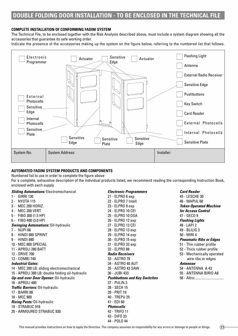
COMPLETE INSTALLATION OF CONFORMING FADINI SYSTEMThe Technical File, to be enclosed together with the Risk Analysis described above, must include a system diagram showing all theaccessories that guarantee its safe working order.Indicate the presence of the accessories making up the system on the figure below, referring to the numbered list that follows.
AUTOMATED FADINI SYSTEM PRODUCTS AND COMPONENTSNumbered list to use in order to complete the figure aboveFor a complete, exhaustive description of the individual products listed, we recommend reading the corresponding Instruction Book,enclosed with each supply.
E lect ron icProgrammer
Actuator
E x t e r n a lPhotocells
InternalPhotocells
SensitiveEdge
SensitivePlate
DOUBLE FOLDING DOOR INSTALLATION - TO BE ENCLOSED IN THE TECHNICAL FILE
Sensitive Edge
SensitiveEdge
SensitivePlate
Actuator
SensitiveEdge
This manual provides instructions on how to apply the Directive. The company assumes no responsibility for any errors or damage to people or things.
Flashing Light
Antenna
External Radio Receiver
Sensitive Edge
Pushbuttons
Key Switch
Card Reader
External Photocells
Internal Photocel ls
Sensitive Plate
Sliding Automations: Electromechanical1 - GIRRI 1302 - NYOTA 1153 - MEC 200 HORIZ.4 - MEC 200 VERT.5 - FIBO 300 (1.5 HP)6 - FIBO 400 (3.0 HP)Swinging Automations: Oil-hydraulic7 - NUPI 668 - HINDI 880 SPRINT9 - HINDI 88010 - MEC 800 SPECIAL11 - APROLI 280 BATT12 - DRIVE 70013 - COMBI 740Industrial Gates:14 - MEC 200 LB: sliding electromechanical15 - APROLI 380 LB: double folding oil-hydraulicUp-and-over Door Opener: Oil-hydraulic16 - APROLI 480Traffic Barriers: Oil-hydraulic17 - BARRI 8818 - MEC 900Rising Posts: Oil-hydraulic19 - STRABUC 91820 - ARMOURED STRABUC 930
Electronic Programmers21 - ELPRO 6 exp22 - ELPRO 7 Intell.23 - ELPRO 9 exp24 - ELPRO 10 CEI25 - ELPRO 10 DSA26 - ELPRO 12 exp27 - ELPRO 13 CEI28 - ELPRO 13 exp29 - ELPRO 14 exp30 - ELPRO 15 exp31 - ELPRO 33 exp32 - ELPRO 88Radio Receivers33 - ASTRO 7834 - ASTRO 40 AUT35 - ASTRO 43 SAW36 - JUBI 433Pushbuttons and Key Switches37 - PULIN 338 - SECH 1539 - PRIT 1940 - TREPU 2541 - EDI 60Photocells42 - TRIFO 1143 - DIFO 3344 - POLO 44
Card Reader45 - LESCHE 3046 - MAPUL 68Token Operated Machinefor Access Control47 - GECO 9Flashing Lights48 - LAPI 249 - BLILIG 350 - MIRI 4Pneumatic Ribs or Edges51 - Thin rubber profile52 - Thick rubber profile53 - Mechanically operated
wire ribs or edgesAntennae54 - ANTENNA A 4355 - ANTENNA BIRIO A856 - Altro:................................
System No. System Address: Installer:

24
DOUBLE FOLDING DOOR INSTALLATION - TO BE ENCLOSED IN THE TECHNICALFILE AND A COPY GIVEN TO THE END USER
MAINTENANCE RECORDThis document must provide a record of all ordinary and extraordinary installation, maintenance and repair operations and anymodifications using original Fadini spare parts.As such, this document must be available for inspections by authorized bodies, and a copy must be given to the end user.The installer will only guarantee the system’s good working order and safety if the maintenance operations are performed by qualifiedtechnical personnel of his employment.
GENERAL INSTALLER AND SYSTEM INFORMATION:Technical Assistance (Name, address, telephone)
Client (Name, address and reference person)
Gate Description (Model)
Gate Leaves (No., material, dimensions, weight)
Power Supply (Power, voltage and absorption)
Function Type (Operator, impulse, automatic)
Installer (Name, address, telephone)
Installation Date
List of Remaining RisksList any risks that have not been completely eliminated with signals, informing the user about the risks that may arise due to incorrect system use.
Date Operation Description Technician’s Signature Client’s Signature
This manual provides instructions on how to apply the Directive. The company assumes no responsibility for any errors or damage to people or things.
25
DOUBLE FOLDING DOOR INSTALLATION
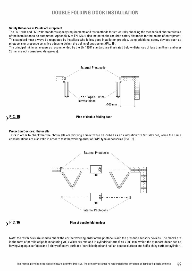
Safety Distances in Points of EntrapmentThe EN 12604 and EN 12605 standards specify requirements and test methods for structurally checking the mechanical characteristicsof the installation to be automated. Appendix C of EN 12604 also indicates the required safety distances for the points of entrapment.This standard must always be respected by installers who follow good installation practice, using additional safety devices such asphotocells or presence sensitive edges to delimit the points of entrapment (Pic. 15).The principal minimum measures recommended by the EN 12604 standard are illustrated below (distances of less than 8 mm and over25 mm are not considered dangerous).
Protection Devices: PhotocellsTests in order to check that the photocells are working correctly are described as an illustration of ESPE devices, while the sameconsiderations are also valid in order to test the working order of PSPE type accessories (Pic. 16).
Note: the test blocks are used to check the correct working order of the photocells and the presence sensory devices. The blocks arein the form of parallelepipeds measuring 700 x 300 x 200 mm and in cylindrical form Ø 50 x 300 mm, which the standard describes ashaving 3 opaque surfaces and 3 shiny reflective surfaces (parallelepiped) and half an opaque surface and half a shiny surface (cylinder).
Plan of double folding door
PIC. 15
PIC. 16
This manual provides instructions on how to apply the Directive. The company assumes no responsibility for any errors or damage to people or things.
200
300
Internal Photocells
External Photocells
200
300
Plan of double folding door
Door open withleaves folded
>500 mm
External Photocells

26
RISK ANALYSIS AND SOLUTIONS ADOPTEDEvery automatic gate must be complete with an analysis of the possible risks to people, therefore a table follows below that shouldbe filled in (after having made a copy of the original) with the main mechanical risks found and relative solutions to be adopted (numberednext to the table) in the most hazardous points listed in Pic. 17.
UNAVOIDABLE RISKSIn the mechanical risk analysis, not all hazards found are avoidable, therefore the EN 12445 and EN 12453 standards make provisionsfor written warnings, both in the Risk Analysis and above all on the hazardous points of the system itself that cannot be protected. Thesesigns should be standard danger signs in black on a yellow background (i.e. protruding handles or doors, or excessive steps or risesin the ground), while for forbidden zones the prohibition and danger signs provided for by the highway code should be used.
TRAFFIC BARRIER INSTALLATION - TO BE ENCLOSED IN THE TECHNICAL FILE
A - Impact and CrushingB - Shearing, Entrapment and CutsC - LiftingD - Impact and Crushing
Solutions Adopted:
1 - OPERATOR COMMAND2 - FORCE REDUCERS3 - SENSITIVE EDGES OR RIBS4 - PHOTOCELLS5 - SENSITIVE PLATES6 - VISUAL WARNING SIGNS7 - ACOUSTIC WARNINGS8 - COVERS9 - other
List of main danger points in a traffic barrier with single and counterbalanced arm
Main mechanical risks to look out for in the system’s danger zones
PIC. 17
C - Shearing D - Entrapment E - Cuts F - HookingA - ImpactB - Crushing
This manual provides instructions on how to apply the Directive. The company assumes no responsibility for any errors or damage to people or things.
A
C
D
B
Installation Type Client: Address:
Date:
Instal lat ion Firm Stamp
Installer Signature
Danger Points (see Pic.17) Mechanical Risks Solutions Adopted
27
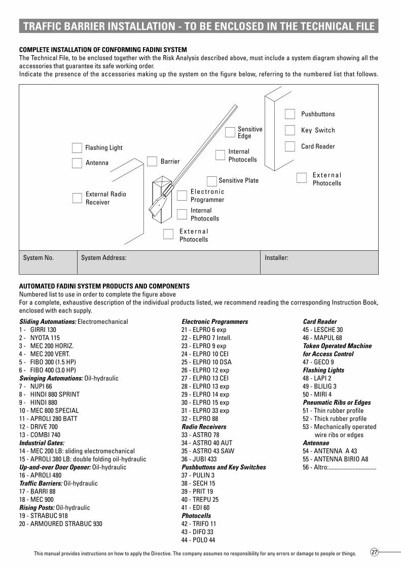
COMPLETE INSTALLATION OF CONFORMING FADINI SYSTEMThe Technical File, to be enclosed together with the Risk Analysis described above, must include a system diagram showing all theaccessories that guarantee its safe working order.Indicate the presence of the accessories making up the system on the figure below, referring to the numbered list that follows.
AUTOMATED FADINI SYSTEM PRODUCTS AND COMPONENTSNumbered list to use in order to complete the figure aboveFor a complete, exhaustive description of the individual products listed, we recommend reading the corresponding Instruction Book,enclosed with each supply.
E lect ron icProgrammer
External RadioReceiver
SensitiveEdge
Flashing Light
Pushbuttons
Key Switch
Card Reader
E x t e r n a lPhotocells
E x t e r n a lPhotocells
InternalPhotocells
Sensitive Plate
TRAFFIC BARRIER INSTALLATION - TO BE ENCLOSED IN THE TECHNICAL FILE
Antenna Barrier
Sliding Automations: Electromechanical1 - GIRRI 1302 - NYOTA 1153 - MEC 200 HORIZ.4 - MEC 200 VERT.5 - FIBO 300 (1.5 HP)6 - FIBO 400 (3.0 HP)Swinging Automations: Oil-hydraulic7 - NUPI 668 - HINDI 880 SPRINT9 - HINDI 88010 - MEC 800 SPECIAL11 - APROLI 280 BATT12 - DRIVE 70013 - COMBI 740Industrial Gates:14 - MEC 200 LB: sliding electromechanical15 - APROLI 380 LB: double folding oil-hydraulicUp-and-over Door Opener: Oil-hydraulic16 - APROLI 480Traffic Barriers: Oil-hydraulic17 - BARRI 8818 - MEC 900Rising Posts: Oil-hydraulic19 - STRABUC 91820 - ARMOURED STRABUC 930
Electronic Programmers21 - ELPRO 6 exp22 - ELPRO 7 Intell.23 - ELPRO 9 exp24 - ELPRO 10 CEI25 - ELPRO 10 DSA26 - ELPRO 12 exp27 - ELPRO 13 CEI28 - ELPRO 13 exp29 - ELPRO 14 exp30 - ELPRO 15 exp31 - ELPRO 33 exp32 - ELPRO 88Radio Receivers33 - ASTRO 7834 - ASTRO 40 AUT35 - ASTRO 43 SAW36 - JUBI 433Pushbuttons and Key Switches37 - PULIN 338 - SECH 1539 - PRIT 1940 - TREPU 2541 - EDI 60Photocells42 - TRIFO 1143 - DIFO 3344 - POLO 44
Card Reader45 - LESCHE 3046 - MAPUL 68Token Operated Machinefor Access Control47 - GECO 9Flashing Lights48 - LAPI 249 - BLILIG 350 - MIRI 4Pneumatic Ribs or Edges51 - Thin rubber profile52 - Thick rubber profile53 - Mechanically operated
wire ribs or edgesAntennae54 - ANTENNA A 4355 - ANTENNA BIRIO A856 - Altro:................................
System No. System Address: Installer:
This manual provides instructions on how to apply the Directive. The company assumes no responsibility for any errors or damage to people or things.
InternalPhotocells

28
TRAFFIC BARRIER INSTALLATION - TO BE ENCLOSED IN THE TECHNICAL FILEAND A COPY GIVEN TO THE END USER
MAINTENANCE RECORDThis document must provide a record of all ordinary and extraordinary installation, maintenance and repair operations and anymodifications using original Fadini spare parts.As such, this document must be available for inspections by authorized bodies, and a copy must be given to the end user.The installer will only guarantee the system’s good working order and safety if the maintenance operations are performed by qualifiedtechnical personnel of his employment.
GENERAL INSTALLER AND SYSTEM INFORMATION:Technical Assistance (Name, address, telephone)
Client (Name, address and reference person)
Gate Description (Model)
Gate Leaves (No., material, dimensions, weight)
Power Supply (Power, voltage and absorption)
Function Type (Operator, impulse, automatic)
Installer (Name, address, telephone)
Installation Date
List of Remaining RisksList any risks that have not been completely eliminated with signals, informing the user about the risks that may arise due to incorrect system use.
Date Operation Description Technician’s Signature Client’s Signature
This manual provides instructions on how to apply the Directive. The company assumes no responsibility for any errors or damage to people or things.

29
TRAFFIC BARRIER INSTALLATION
Safety Distances in Points of EntrapmentThe EN 12604 and EN 12605 standards specify requirements and test methods for structurally checking the mechanical characteristicsof the installation to be automated. Appendix C of EN 12604 also indicates the required safety distances for the points of entrapment.This standard must always be respected by installers who follow good installation practice, using additional safety devices such asphotocells or presence sensitive edges to delimit the points of entrapment (Pic. 18).The principal minimum measures recommended by the EN 12604 standard are illustrated below (distances of less than 8 mm and over25 mm are not considered dangerous).on sono considerati pericolosi).
Protection Devices: PhotocellsTests in order to check that the photocells are working correctly are described as an illustration of ESPE devices, while the sameconsiderations are also valid in order to test the working order of PSPE type accessories (Pic. 19).
Traffic Barriers
Traffic Barrier
Note: the test blocks are used to check the correct working order of the photocells and the presence sensory devices. The blocks arein the form of parallelepipeds measuring 700 x 300 x 200 mm and in cylindrical form Ø 50 x 300 mm, which the standard describes ashaving 3 opaque surfaces and 3 shiny reflective surfaces (parallelepiped) and half an opaque surface and half a shiny surface (cylinder).
PIC. 18
PIC. 19
Protective covers are necessaryto protect spaces of less than 300 mmbetween the counterbalanced arm andthe adjacent wall
This manual provides instructions on how to apply the Directive. The company assumes no responsibility for any errors or damage to people or things.
<300 mm
500
Pair of InternalPhotocells
700
300
Test blocks200 70
0
300200 Pair of ExternalPhotocells
500

30
RISK ANALYSIS AND SOLUTIONS ADOPTEDEvery automatic gate must be complete with an analysis of the possible risks to people, therefore a table follows below that shouldbe filled in (after having made a copy of the original) with the main mechanical risks found and relative solutions to be adopted (numberednext to the table) in the most hazardous points listed in Pic. 20.
UNAVOIDABLE RISKSIn the mechanical risk analysis, not all hazards found are avoidable, therefore the EN 12445 and EN 12453 standards make provisionsfor written warnings, both in the Risk Analysis and above all on the hazardous points of the system itself that cannot be protected. Thesesigns should be standard danger signs in black on a yellow background (i.e. protruding handles or doors, or excessive steps or risesin the ground), while for forbidden zones the prohibition and danger signs provided for by the highway code should be used.
RISING POST INSTALLATION - TO BE ENCLOSED IN THE TECHNICAL FILE
A - Impact, Lifting and HookingB - Entrapment Solutions Adopted:
1 - OPERATOR COMMAND2 - FORCE REDUCERS3 - SENSITIVE EDGES OR RIBS4 - PHOTOCELLS5 - SENSITIVE PLATES6 - VISUAL WARNING SIGNS7 - ACOUSTIC WARNINGS8 - COVERS9 - other
List of main danger points in a rising post
Main mechanical risks to look out for in the system’s danger zones
A - Impact B - Shearing C- Entrapment D – Cuts – E Hooking
PIC. 20
This manual provides instructions on how to apply the Directive. The company assumes no responsibility for any errors or damage to people or things.
A
B
Installation Type Client: Address:
Date:
Instal lat ion Firm Stamp
Installer Signature
Danger Points (see Pic. 20) Mechanical Risks Solutions Adopted

31
COMPLETE INSTALLATION OF CONFORMING FADINI SYSTEMThe Technical File, to be enclosed together with the Risk Analysis described above, must include a system diagram showing all theaccessories that guarantee its safe working order.Indicate the presence of the accessories making up the system on the figure below, referring to the numbered list that follows.
AUTOMATED FADINI SYSTEM PRODUCTS AND COMPONENTSNumbered list to use in order to complete the figure aboveFor a complete, exhaustive description of the individual products listed, we recommend reading the corresponding Instruction Book,enclosed with each supply.
ElectronicProgrammer
External RadioReceiver
Flashing Light
Pushbuttons
Key Switch
Card Reader ExternalPhotocells
ExternalPhotocells
InternalPhotocells
Sensitive Plate
Antenna
RISING POST INSTALLATION - TO BE ENCLOSED IN THE TECHNICAL FILE
SensitivePlate
Internal Photocells
This manual provides instructions on how to apply the Directive. The company assumes no responsibility for any errors or damage to people or things.
Sliding Automations: Electromechanical1 - GIRRI 1302 - NYOTA 1153 - MEC 200 HORIZ.4 - MEC 200 VERT.5 - FIBO 300 (1.5 HP)6 - FIBO 400 (3.0 HP)Swinging Automations: Oil-hydraulic7 - NUPI 668 - HINDI 880 SPRINT9 - HINDI 88010 - MEC 800 SPECIAL11 - APROLI 280 BATT12 - DRIVE 70013 - COMBI 740Industrial Gates:14 - MEC 200 LB: sliding electromechanical15 - APROLI 380 LB: double folding oil-hydraulicUp-and-over Door Opener: Oil-hydraulic16 - APROLI 480Traffic Barriers: Oil-hydraulic17 - BARRI 8818 - MEC 900Rising Posts: Oil-hydraulic19 - STRABUC 91820 - ARMOURED STRABUC 930
Electronic Programmers21 - ELPRO 6 exp22 - ELPRO 7 Intell.23 - ELPRO 9 exp24 - ELPRO 10 CEI25 - ELPRO 10 DSA26 - ELPRO 12 exp27 - ELPRO 13 CEI28 - ELPRO 13 exp29 - ELPRO 14 exp30 - ELPRO 15 exp31 - ELPRO 33 exp32 - ELPRO 88Radio Receivers33 - ASTRO 7834 - ASTRO 40 AUT35 - ASTRO 43 SAW36 - JUBI 433Pushbuttons and Key Switches37 - PULIN 338 - SECH 1539 - PRIT 1940 - TREPU 2541 - EDI 60Photocells42 - TRIFO 1143 - DIFO 3344 - POLO 44
Card Reader45 - LESCHE 3046 - MAPUL 68Token Operated Machinefor Access Control47 - GECO 9Flashing Lights48 - LAPI 249 - BLILIG 350 - MIRI 4Pneumatic Ribs or Edges51 - Thin rubber profile52 - Thick rubber profile53 - Mechanically operated
wire ribs or edgesAntennae54 - ANTENNA A 4355 - ANTENNA BIRIO A856 - Altro:................................
System No. System Address: Installer:

32
MAINTENANCE RECORDThis document must provide a record of all ordinary and extraordinary installation, maintenance and repair operations and anymodifications using original Fadini spare parts.As such, this document must be available for inspections by authorized bodies, and a copy must be given to the end user.The installer will only guarantee the system’s good working order and safety if the maintenance operations are performed by qualifiedtechnical personnel of his employment.
RISING POST INSTALLATION - TO BE ENCLOSED IN THE TECHNICAL FILE
GENERAL INSTALLER AND SYSTEM INFORMATION:Technical Assistance (Name, address, telephone)
Client (Name, address and reference person)
Gate Description (Model)
Gate Leaves (No., material, dimensions, weight)
Power Supply (Power, voltage and absorption)
Function Type (Operator, impulse, automatic)
Installer (Name, address, telephone)
Installation Date
List of Remaining RisksList any risks that have not been completely eliminated with signals, informing the user about the risks that may arise due to incorrect system use.
Date Operation Description Technician’s Signature Client’s Signature
This manual provides instructions on how to apply the Directive. The company assumes no responsibility for any errors or damage to people or things.

33
RISING POST INSTALLATION
Safety Distances in Points of EntrapmentThe EN 12604 and EN 12605 standards specify requirements and test methods for structurally checking the mechanical characteristicsof the installation to be automated. Appendix C of EN 12604 also indicates the required safety distances for the points of entrapment.This standard must always be respected by installers who follow good installation practice, using additional safety devices such asphotocells or presence sensitive edges to delimit the points of entrapment.The principal minimum measures recommended by the EN 12604 standard are illustrated below (distances of less than 8 mm and over25 mm are not considered dangerous).
Protection Devices: PhotocellsTests in order to check that the photocells are working correctly are described as an illustration of ESPE devices, while the sameconsiderations are also valid in order to test the working order of PSPE type accessories (Pic. 21).
Rising post
Note: the test blocks are used to check the correct working order of the photocells and the presence sensory devices. The blocks arein the form of parallelepipeds measuring 700 x 300 x 200 mm and in cylindrical form Ø 50 x 300 mm, which the standard describes ashaving 3 opaque surfaces and 3 shiny reflective surfaces (parallelepiped) and half an opaque surface and half a shiny surface (cylinder).
PIC. 21
This manual provides instructions on how to apply the Directive. The company assumes no responsibility for any errors or damage to people or things.
Test blocks

34
Electrical and Electromagnetic Compatibility RisksMeccanica Fadini manufactures and markets electronic control and management accessories in compliance with current regulations:- LV Low Voltage Directive (50 V – 1000 V A/C) 73/23/EEC and subsequent 93/68/EC- EMC Electromagnetic Compatibility Directive 89/336/EEC and subsequent 93/68/EC- R&TTE Radio & Telecommunications Terminal Equipment 99/05/ECTotal reliability and safety in complete compliance with regulations is only guaranteed for electronic and electromechanical appliancesif installed in an automatic system consisting of original Fadini components.
- Use CE marked components and materials in compliance with Low Tension Directive 73/23/EEC andsubsequent amendments 93/68/EC
All electrical components in the system must be expertly installed in keeping with current standards,and relative tests must be performed.
- Use CE marked components and materials in compliance with the EMC Directive on ElectromagneticCompatibility 89/336/EEC and subsequent amendments 93/68/EC
- Use activation devices that conform to EN 12453 Standards and safety accessories that comply withEN 12978 Standards
- If using hydraulic activation devices, they must conform to the EN 982 standard... Or:- If using pneumatic activation devices, they must conform to the EN 983 standard
- Check that the activation device resumes normal function after a fault or power failure
- Install an omnipolar switch for electrical isolation, positioning it in a place protected from involuntaryor unauthorized use
- Install the command devices in safe places, ensuring that the individual activation commands areunderstood by the user
- Use CE marked radio control units in compliance with R&TTE Directive 99/05/EC, which comply withthe frequencies permitted by the legislation of each individual country
- Install and instruct the user about how to operate the activation device unlocking operations in orderto open and close the gate. Check that the user understands the unlocking device or alternativesolutions
- If necessary, install a stop device in compliance with standard EN 418, ensuring that this device doesnot entail additional risks or prevent the safety devices from operating correctly
Direct and IndirectContacts.Electrical energy dispersion
ElectromagneticCompatibility Risks
Risk Type Assessment criteria and solutions to be adopted
- Install the flashing light that signals the automatic gate’s movement in a visible position; upon request,integrate this with some reflectors on the gate.
- Attach a sign to the gate indicating danger while the automatic gate is in movement. Also attach signsindicating all the remaining risks and indicating all unsuitable forms of use
- Attach the plaque with the CE mark and current standard indications
- Provide the user with the User Instructions, safety warnings and CE declaration of conformity
- General control and maintenance every 6 months, especially for the safety devices; record all operationsin the Maintenance Record in keeping with standard EN 12635
- Provide written information in the Maintenance Record and User Instructions about the presence ofany remaining risks
Safety limitations due tofaults or power failure
Energy types other thanelectricity
Turning the ActivationDevice On and Off
Mains Switch
Command Uniformity
Entrapment Risks
Emergency Stop
Risk Type Assessment criteria and solutions to be adopted
Risk Type Assessment criteria and solutions to be adopted
Safety of Activation Devices and Control and Safety Accessories
Signal Accessories
Signs
Marks
User Instructions
Maintenance
Remaining risks
Added safety through warning signs
This manual provides instructions on how to apply the Directive. The company assumes no responsibility for any errors or damage to people or things.

35
Measuring the impact and crushing forcesStandards EN 12445 and EN 12543 consider the forces manifested by a gate during movement as a way for learning about risks duringthe Risk Analysis and intervening quickly in order to prevent them.The standards make provisions for the use of an appropriate tool for measuring the impact and crushing force of the main opening andclosing edge, providing detailed descriptions of all this device’s technical characteristics and measurement procedures. Therefore,all measurements should be made three times in each point indicated and for three different gate openings. The measurement of themaximum peak and the progress of the force measured must respect the maximum values given in the following table and in Pic. 22.
FD = Dynamic force of impact, max. value 1˙400 NSF = Crushing force, max. value 150 NDT = Dynamic time, max. value 0.75 sTo = Total time, max. value 5 s
Force [N]
Time [s]
1˙400 N
400 N
150 N
25 N
0,75 s
5 s
Dynamic Force ofImpact DF
Static Force ofCrushing SF
Remaining force
PIC. 22
400 N 1˙400 N 1˙400 N
400 N 1˙400 N 1˙400 N
400 N 400 N 1˙400 N
400 N 400 N 1˙400 N
Type of Automation
Sliding and SideFolding Doors
Swinging Doors andDoubleFolding Doors
Sectional Doors
Barriers,Up-and-over Doors,Rising Posts
Closure Edge andOpposite Edges Between flat areas
>0,1 m2 with longsides <100 mm50 - 500 mm >500 mm
Dynamic Forces DF
This manual provides instructions on how to apply the Directive. The company assumes no responsibility for any errors or damage to people or things.

Via Mantova, 177/A - 37053 Cerea (Verona) Italy - Tel. 0442 330422 r.a. - Fax 0442 331054 - e-mail: [email protected] - www.fadini.net
®
s.n.c.
This manual provides instructions on how to applythe Directive. The company assumes noresponsibility for any errors or damage to peopleor things.
The manufacturer reserves the right to makechanges to this guide at any time without advancenotice and recommends reading the cited safetystandards in order to gain a better understandingof them.
AUTOMATIC GATE MANUFACTURERS
Line
agra
fica
12-2
003