Embed Size (px)
Citation preview

1
Safe Work Australia Contact Information Phone 1300 551 832 | Email [email protected] | Web www.swa.gov.au
978-1-74361-749-6 [Multi-Vol. Set] 978-1-74361-743-4 [PDF] 978-1-74361-744-1 [DOCX]
This Guide provides information for people who design, redesign or modify plant to be used in a workplace. Plant includes machinery, equipment, appliances, containers, implements and tools and components or anything fitted or connected to those things. Some examples of plant include lifts, cranes, computers, machinery, scaffolding components, conveyors, forklifts, vehicles, power tools and amusement devices.
This Guide should be read and used together with the:
� Code of Practice: Safe design of structures – this Code covers safe design more generally including the duties of designers, the key elements of a safe design process and integrating design and risk management, and
� Code of Practice: Managing risks of plant in the workplace – this Code covers managing health and safety risks of plant from installation, commissioning and use through to its decommissioning and dismantling. It also includes information on plant hazards, risks and control measures.
The Guide is part of a series of guidance material for plant that includes information on the safe design, manufacture, import and supply of plant.
This Guide applies to the design of structures where items of plant are designed as a structural component or are assembled to form a structure, for example scaffolding. A structure is anything constructed, whether fixed or moveable, temporary or permanent. Further information on the safe design of structures is in the Code of Practice: Safe design of structures.
WHAT IS SAFE DESIGN?Safe design means the integration of control measures early in the design process to eliminate or, if this is not reasonable practicable, minimise risks to health and safety throughout the lifecycle of the plant being designed.
Safe design begins at the concept development phase when choices are made about design, materials used and methods of manufacture. In these early phases there is more chance to design-out hazards or incorporate compatible risk control measures with the original design concept and functional requirements of the product.
Safe design applies to every phase in the plant lifecycle, from design to disposal. This means thinking about potential hazards and design solutions as the plant is manufactured, transported, installed, commissioned, used, maintained, repaired, de-commissioned, dismantled, disposed of or recycled.
WHO IS A DESIGNER?A designer is a person conducting a business or undertaking whose profession, trade or business involves them in:
� preparing sketches, plans, drawings or models including prototypes for plant to be used, or could reasonably be expected to be used at a workplace including variations to a plan or changes to the plant, and
� making decisions—for incorporation into a design—that may affect the health or safety of people who manufacture, use or carry out other activities with the plant.
Designers include design professionals like engineers, industrial designers and designers of plant systems, for example software and electrical systems.
A person will also have the duties of a designer if they change the design during manufacture or change existing plant so that new measures for controlling risk are needed. For example, if the maximum working radius of a mobile crane is increased by fitting a longer boom, a new load chart should be prepared to control the increased risk of the crane overturning. The person designing the boom extension should contact the original designer to check the new boom extension does not compromise the existing design criteria or safety factors.
GUIDE FOR SAFE DESIGN OF PLANT

2
JULY 2014
GUIDE FOR SAFE DESIGN OF PLANT
WHAT HEALTH AND SAFETY DUTIES DO PLANT DESIGNERS HAVE?A designer must ensure, so far as is reasonably practicable, plant is designed without risks to health and safety throughout the plant’s whole lifecycle.
Risks to health and safety may exist throughout the lifecycle of the plant from manufacturing through to installing, commissioning, using, maintaining, repairing, decommissioning and disposing of the plant. There are often a number of people involved with plant during its lifecycle. A person conducting a business or undertaking can have more than one duty and more than one person can have the same duty at the same time. For example, sometimes a plant manufacturer, importer or supplier will also have the duties of a designer.
Providing and obtaining informationDesigners have obligations to provide information about plant so other duty holders can fulfil their responsibility to manage risks and plant users are protected from risks to health and safety.
Information must be passed on from the designer through to the manufacturer, importer, supplier and the end user. This information includes:
� the purpose for which plant was designed (the intended use)
� the results of calculations, analysis, testing or examination necessary to use, inspect, commission and maintain plant safely
� details about plant design registration, if applicable, and
� any conditions necessary for the plant to be used safely.
It is also helpful for designers to provide information on the relevant technical standards used in the plant’s design so the plant can be manufactured, installed and used in accordance with those standards.
Information should be easily understood by the person receiving it. Information may be a combination of writing or visual information like drawings, signs, symbols, diagrams or videos. Where visual information is provided it should meet the relevant standard.
The designer should record details of testing and examination carried out and must ensure they are made available to the design verifier if plant design registration is required. For example, if plant is required to be located a specific distance from other plant written instructions must be provided for the manufacturer, supplier, installer, owner and end user.
Information flow between the designer and manufacturerDesigners must provide specific information to the manufacturer to enable the plant to be manufactured in accordance with the design specifications. If relevant, information must be provided on:
� installing, commissioning, using, handling, storing, decommissioning and dismantling the plant
� hazards and risks associated with using the plant
� testing or inspections to be carried out
� systems of work and competency of users necessary for the plant to be used safely, and
� emergency procedures if there is a malfunction.
If the manufacturer tells the designer there are safety issues with the design, the designer must revise the information to take account of these concerns, or tell the manufacturer in writing the reasons why revisions are not necessary.
Designer information that can be provided to the manufacturer is in Table 1.

3
JULY 2014
GUIDE FOR SAFE DESIGN OF PLANT
Table 1 Designer information that should be provided to the manufacturer
Designer information that can be provided to the manufacturer
Manufacturing plant � specific conditions relating to the method of manufacture
� instructions for fitting or refitting plant parts and their location on other components of the plant or their housings where errors could be made when installing the plant
� instruction where hot or cold parts or material may create a hazard
� specifications of material
� wiring diagrams
� specifications for proprietary items e.g. electric motors
� component specifications including drawings and tolerances
� assembly drawings
� assembly procedures including specific tools or equipment to be used
� manufacturing processes e.g. requirements for welding
� details of hazards presented by materials during manufacturing, and
� safety outcomes for programming.
Transporting, handling and storing plant
� dimensions and weight
� handling instructions e.g. application points for lifting equipment, and
� conditions for storage.
Installing and commissioning plant
� exposure to dangerous parts before installing guards
� lifting procedures
� plant interacting with people
� plant interacting with other plant e.g. connected services and installations
� stability during installation
� the proposed method for installing and commissioning including tests that should be carried out
� using special tools, jigs, fixtures and appliances necessary to minimise the risk of injury during installation
� concealed installations e.g. gas or fuel lines, and
� environmental factors affecting installation and commissioning.
Using, inspecting and testing plant
� intended uses for the plant including prohibited uses
� operating procedures
� safe entry and exit
� requirements for maintenance and repair e.g. nature and frequency of maintenance, disposal of hazardous by-product and consumables
� emergency situations e.g. types of firefighting equipment
� exposure to hazardous chemicals
� how environmental conditions effect using the plant
� the results or documentation of tests and examinations carried out on the plant and design
� de-commissioning, dismantling and disposing of plant
� known residual risks i.e. those that cannot be eliminated or sufficiently minimised by design

4
JULY 2014
GUIDE FOR SAFE DESIGN OF PLANT
Designer information that can be provided to the manufacturer
� details of control measures e.g. personal protective equipment (PPE) to further minimise the risks associated with plant
� information on administrative control measures, and
� requirements for special tools needed to use or maintain plant.
Design verification and registrationThe Work Health and Safety (WHS) Regulations lists the plant that requires design registration before the plant can be supplied (registrable plant). For registrable plant, the information to be provided by the designer to the manufacturer should include the plant design registration number. This provides evidence the plant design has been registered under the WHS Regulations. The plant design registration number is not necessary where the manufacturing process relates to the development of a prototype to test the design.
To register a plant design it must be verified by a design verifier who must provide a statement that the design is in accordance with published technical standards or engineering principles nominated by the designer. The statement must:
� include the design
� be in writing and signed by the design verifier and include their name and business address
� have drawings or other documents capable of being kept in electronic form, and
� if applicable, also include the design verifier’s qualifications and the name and business address of the organisation for which the design verifier works.
Design verifierA design can only be verified by a person who is eligible to be a design verifier under the WHS Regulations. People who are competent to verify the design of plant include those who:
� have educational or vocational qualifications in an engineering discipline relevant to the design to be verified, or
� have knowledge of the technical standards relevant to the design to be verified, or
� have the skills necessary to independently verify the design was produced in accordance with the published technical standards and engineering principles used in the design, or
� are certified by a body accredited or approved by the Joint Accreditation System—Australia and New Zealand or an equivalent overseas body to carry out conformity assessments of the design against the relevant technical standards.
For example, a person accredited by a third party certifier may have the qualifications and experience to be a design verifier for a particular type of plant.
Similarly, a design verifier could also be someone who is:
� registered on the National Professional Engineers Register administered by the Institution of Engineers Australia and is determined by that institution as competent to verify the design, or
� a member of the Institution of Engineers Australia with the status of Chartered Professional Engineer.
The design verifier, who may be in-house or an independent contractor, must not have been involved in the plant design process. However a design verifier may verify more than one design at the same time as long as the verifier was not involved in the plant design process. For example, a company designs passenger lifts and vehicle hoists—once a lift design is finalised a design verifier starts to verify the lift design. Part way through verifying the lift design, a new vehicle hoist design is finalised and the company asks the same design verifier to also verify the new vehicle hoist design. This is allowed because the design verifier was not involved in either design process and the verifier is only verifying plant designs already
5
JULY 2014
GUIDE FOR SAFE DESIGN OF PLANT
developed. This also applies if the designs are within the same plant category, for example two different passenger lift designs.
Where the design verifier is engaged by the person conducting a business or undertaking that produced the design that person must have a quality system in place that has been certified by a body accredited or approved by the Joint Accreditation System – Australia and New Zealand.
DESIGNING PLANT TO CONTROL RISKThe design brief should include a requirement to apply a risk management process in the design phase. A systematic approach to integrating design and risk management is described in Figure 1 below.
The safe design of plant is usually a repetitive process. After the initial control measures are incorporated into the design, the design should be reviewed to determine whether there are remaining risks and whether redesign can eliminate or minimise these risks. Various parts of plant design and risk management process are discussed below.
Pre-design and concept development phaseThis phase involves:
� establishing the intended use of the plant, its functions and limitations
� identifying the roles and responsibilities for the project and establishing co-operative relationships with clients, manufacturers and users of the plant including those who maintain and repair the plant, and
� researching and consulting to assist in identifying hazards and assessing and controlling risks.
Intended use of plantThe intended use of the plant including its functions and limitations (see Table 2) can be determined by looking at:
� the expected place of use e.g. environment and supporting surfaces
� intended functions and operating modes
� safe use requirements including reasonably foreseeable misuse
� planned service life
� relevant standards and specifications e.g. what is produced and materials to be used
� possible malfunctions and faults
� testing, maintenance and repair requirements
� the people interacting with the plant, and
� other products interacting with or related to the plant.
Table 2 Examples of plant functions and limits
Plant limitations Examples
Use Intended use, production rates, cycle times and working load limits
Space Range of movement and access for maintenance
Time Wear and tear of materials and use of fluids
Environment Temperature, humidity, noise and location
Interface Other plant, energy sources and user interface
Technology Intuitive decision making and visual stimulus overload

6
JULY 2014
GUIDE FOR SAFE DESIGN OF PLANT
FIGURE 1 A systematic approach to integrating design and risk management

7
JULY 2014
GUIDE FOR SAFE DESIGN OF PLANT
Identifying the hazardsThe first step in the risk management process is to identify all hazards. Hazard identification should be done as early as possible in the concept development and design phases. This involves finding the things and situations that could potentially cause harm to people throughout the plant’s lifecycle and the reasonably foreseeable hazards associated with each activity. Hazards relating to plant are often caused by:
� the plant itself e.g. hazards associated with a forklift could include the plant’s mobility, electrical, hydraulic and mechanical power sources, moving parts, load-carrying capacity and user protection, and
� how and where the plant is used e.g. forklift hazards may arise from the load being lifted, the size of the area where it is used and the slope or evenness of the ground.
Hazards may be identified by looking at the workplace and how work is carried out. It is also useful to talk to workers, manufacturers, importers, suppliers and health and safety specialists and review relevant information, records and incident reports.
Table 3 lists things to consider when looking for plant hazards.
Table 4 shows examples of potential plant hazards and phases of the plant lifecycle after the design has been completed where people might be exposed to plant hazards.
Table 3 Things to consider to identify plant hazards
Things to consider to identify plant hazards
Hazards � Can the plant cause injury from entanglement, crushing, trapping, cutting, stabbing, puncturing, shearing, abrasion, tearing or stretching?
� Can the plant create hazardous conditions from pressurised content, electricity, noise, radiation, friction, vibration, fire, explosion, temperature, moisture, vapour, gases, dust, ice, hot or cold parts?
� Can the plant cause injury from lack of guarding of moving parts?
� Can the plant cause injury as a result of unexpected start-up?
� Can the plant cause injury or ill health from poor ergonomic design?
Suitability � Is the plant fit for its intended purpose? What is likely to happen if it is used for a purpose other than the intended purpose?
� Are the materials used to make the plant suitable?
� Are plant accessories fit for their intended purpose?
� Is the plant stable? Could it roll over?
� If the plant is intended to lift and move people, equipment or materials, is it capable of doing this?
Access � Is access to the plant necessary when installing, using and maintaining the plant or in an emergency?
� Can workers access the plant safely without being injured by the plant or the risk of slips, trips and falls e.g. a walkway, gantry, elevated work platform or fixed ladder?
Location � Does the plant affect the safety of the area where it will be located e.g. what is its impact on the design and layout of the workplace?
� Does the location affect the safety of the plant e.g. environmental conditions, terrain and work area?
� Will there be people or other plant nearby? What effect would this have?

8
JULY 2014
GUIDE FOR SAFE DESIGN OF PLANT
Things to consider to identify plant hazards
Systems of work
� Do the systems of work for the plant create hazards?
� Does the plant’s safety depend on the competency of its users?
� Have users and others working near the plant received relevant training, information, instruction and supervision needed to ensure they are safe?
Unusual situations
� What unusual situations or misuse could occur?
� What would happen if the plant failed? Would it result in loss of contents, loss of load, unintended ejection of work pieces, explosion, fragmentation or collapse of parts?
� Is it possible for the plant to move or be operated accidently?
Table 4 Examples of plant hazards and phases of the plant lifecycle
Potential hazards Phases of the plant lifecycle
� mechanical e.g. crushing, cutting, trapping, shearing and high pressure fluids
� electrical
� thermal
� noise
� vibration
� radiation
� hazardous chemicals
� slipping, tripping and falling
� manual handling
� confined spaces
� environmental conditions, and
� hazards resulting from a combination of the above.
� manufacture
� storage
� packing and transportation
� unloading and unpacking
� assembly
� installing
� commissioning
� using
� cleaning and adjustment
� inspection
� planned and unplanned maintenance or repair
� decommissioning
� dismantling, and
� disposal and recycling.
Assessing and controlling risksA risk assessment involves considering what could happen if someone is exposed to a hazard and the likelihood of it happening. A risk assessment can be done with varying degrees of detail depending on the complexity of the plant and the type of information available. Specific risk analysis tools and techniques may be needed to assess the different types of plant used at the workplace.
Risk controls are ranked from the highest level of protection and reliability to the lowest. This ranking is known as the hierarchy of risk controls. Risk controls must effectively eliminate the risk or, where that is not reasonably practicable, minimise the risk. Elimination is the most effective control measure and must always be considered before anything else.
Many hazards can be addressed at the design phase. For example, designing machinery to produce low noise levels is more effective than providing workers with PPE. This also avoids costly changes to plant after it has been manufactured.
If eliminating the risk is not reasonably practicable, you must consider using substitution, isolation or engineering controls, or a combination of these control measures, to minimise the risk. The designer should aim to use higher level controls and avoid administrative controls and the use of PPE as these are provide the lowest form of control.

9
JULY 2014
GUIDE FOR SAFE DESIGN OF PLANT
Further information on risk assessment and control is in the:
� Code of Practice: How to manage work health and safety risks, and
� Code of Practice: Managing the risks of plant in the workplace.
Information sources on managing risksThere are a range of information sources to help manage risks associated with plant and the systems of work used in connection with the plant including:
� the WHS Act and Regulations, codes of practice and technical standards about designing, manufacturing, testing and using plant
� injury, faults, incident reports and plant failure data kept by manufacturers and users of the same or similar types of plant
� statistics, hazard alerts or other reports from regulators, unions, employer associations, specialists, professional bodies representing designers, manufacturers, or engineers
� information and documentation supplied by designers or manufacturers on safety and health issues e.g. test reports on previous designs or similar plant, and
� reports or articles from work health and safety journals, technical references or data bases.
Specific information may come from:
� inspecting failed plant returned by users
� developing prototypes and inspecting and testing their design and manufacture, and
� conducting ‘walk-through’ surveys of the workplace where the plant will be used before beginning the design process and while the plant is being installed or erected—the latter to look for hazards which may be introduced during installation.
Where possible, talk to other plant designers, manufacturers, installers and users. People working with the same or similar plant are often well aware of what can go wrong and why and how the work environment can change. It also enables issues to be discussed, for example whether it is possible to use alternative design materials for a safer design.
Design phaseThe design phase may involve:
� developing a prototype or initial design
� testing, trialling or evaluating the prototype or design
� redesigning to control any remaining risks, so far as is reasonably practicable, and
� finalising the design and preparing risk control plans for the lifecycle of the product.
Some hazards may be addressed by applying existing solutions in published technical standards. Alternatively a risk management process should be used to develop and select the most effective control measure. Proven engineering best practice may also be applied if there are no relevant standards.
Technical standardsA plant designer may use technical standards or a combination of standards and engineering principles relevant to the design requirements as long as the design meets regulatory requirements. Engineering principles include, for example mathematical or scientific procedures outlined in an engineering reference or standard.

10
JULY 2014
GUIDE FOR SAFE DESIGN OF PLANT
Testing and examining plantAnalysis, testing or examination that may be necessary to ensure, so far as is reasonably practicable, that the plant is designed without risks to people’s health and safety must be carried out by the designer. Testing may include developing a prototype to:
� simulate the normal range of operational capabilities
� test design features to ensure ‘fail safe’ operation
� measure imposed stresses on critical components to ensure maximum design stresses are not exceeded
� test critical safety features like over-speed and over-pressure devices under both normal and adverse operational conditions, and
� develop overload testing procedures to ensure plant safety when plant is misused.
Records of tests and examinations must be maintained by the designer.
SAFE DESIGN CONSIDERATIONS
Designing plant which is safe to useA designer should consider:
� the required skill levels to use or maintain the plant
� the complexity of functions a user can be expected to perform
� the need for and the location of items to ensure proper use and prevent user errors e.g. aids, guides, indicators, guards, mounted instruction, signs, symbols and name plates
� ensuring plant design is fail safe at least to the category, performance and safety level determined by the plant risk assessment
� the layout of work stations e.g. the view of work being performed and the position of the worker in relation to plant controls
� instrumentation needed at each work station or cabin and the layout of the instrumentation
� devices, tools or controls the user and support people need to carry out their jobs safely
� the options available to allow quick recovery or to maintain the safety and integrity of the system if the user makes an error or the plant fails
� whether the user of the plant is accessible if help is needed
� environmental conditions that may impair user performance e.g. long periods where the user carries out physical or repetitive activity or inactivity in a hot or cold environment, and
� separating people including the user from entrapment when using plant e.g. being caught between the plant and other objects in use.
Designers should also consider predictable human behaviour and never assume those who use or maintain plant have a full appreciation of essential safety features. Where user error is likely, higher order control measures should be incorporated into the design.
For example, a driver uses a tractor to haul a hydraulically operated tilt-up trailer loaded with grain. The gear lever of the tractor is positioned close to the control lever which operated the tip-up mechanism of the trailer. While underway, the driver’s arm moves the control lever slightly so the trailer tray began to lift. The trailer rises and eventually overturns. If the possibility of this type of incident occurring had been anticipated at the design phase these levers would have been located far enough away from each other so the operator did not accidentally activate the wrong mechanism.
For power operated plant with a seat belt, there may be a risk that operators regularly getting on and off the plant may not wear the seatbelts. If the plant is designed so a seat belt in-use sensing system and the engine are interlocked then the operator will need to use the seat belt.

11
JULY 2014
GUIDE FOR SAFE DESIGN OF PLANT
Physical and intellectual characteristics of usersPlant should be designed to take into account the range of physical characteristics and intellectual ability of likely users. Designers should take into account information about the range of human dimensions and capabilities, for example height, reach and weight, to provide an optimum match between plant and users. Anthropometry—that is human body measurement—data should be considered. Designers should consider the varying anthropometrics of cultural groups likely to use the plant.
If information is available on who will be using the plant the designer might also tailor the plant design to meet the needs of specific people.
A designer should:
� apply ergonomic design principles so when the plant is being used properly the user’s discomfort, fatigue and psychological stress are minimised, so far as is reasonably practicable
� take into account the ability of workers e.g. if people with specific disabilities will use the plant, and
� consider whether the plant could be misused or how uncontrolled physical movements could impact the plant’s operation.
Minimising human errorHuman error is not always the result of carelessness or negligence. Sometimes the desire for extra speed, increased production and making tasks easier mean guards are bypassed or removed. Workers may become bored and distracted with repetitious work or use unsafe work practices to overcome poor plant design. For example, locating two important operator controls close together which are of similar shape or size may lead to the user mistakenly operating the wrong control.
Workers have a responsibility to take reasonable care for their own health and safety and must not adversely affect the health and safety of others. Workers must comply with any reasonable instruction and co-operate with any reasonable policy or procedure. Workers should not use unsafe practices or deliberately bypass guarding on plant.
Designers should be aware of the factors contributing to human error when designing plant including:
� forgetfulness
� workers’ conscientiousness to ‘get the job done’ or to ‘find a better way’
� capacity to understand information
� psychological or cultural environment
� habit
� accepted practice
� fatigue, and
� level of training.
Further information on human error is in Appendix A.
Reasonably foreseeable misuseSometimes plant may be used for things it was not designed for or originally intended. For example, where an excavator is used to lift and transport concrete pipes or when a front end loader is used as a crane. When designing plant it is helpful for the risk of reasonably foreseeable misuse to be assessed and acceptable control measures incorporated in the design. One way of identifying potential misuse is by reviewing incident reports for similar types of plant.

12
JULY 2014
GUIDE FOR SAFE DESIGN OF PLANT
Environmental conditionsA designer should consider the hazards created by physical, environmental and operational conditions which plant will be exposed to during its lifecycle. For example, where moving parts are exposed to dust which could cause the plant to malfunction a designer should incorporate effective dust covers into the design.
A designer can also contribute to minimising the environmental hazards by providing instructions to erectors and installers of plant about positioning of the plant. If a user is physically uncomfortable using the plant this may lead to inattention, carelessness or fatigue which may result in an incident. For example, a poorly designed workstation or cabin which does not provide enough sun and heat protection for the user could lead to heat exhaustion or dehydration.
Erecting and installing plantA designer must, so far as is reasonably practicable, ensure hazards from erecting and installing plant are eliminated or minimised. For example, poor access to fasteners like clips and bolt holes may mean an erector or installer needs to work at height, stretch or bend at an unnatural angle. This could result in a risk of fall or musculoskeletal injury to the erector or installer.
Designers should also consider the stability of plant when it is assembled, erected or installed and whether special supports are needed if a partly complete plant item or structure is unstable.
Further information is in the:
� Code of Practice: Hazardous manual tasks, and
� Code of Practice: Managing the risk of falls in the workplace.
MaintenanceA designer’s responsibility extends to eliminating or minimising the risks associated with maintaining the plant, so far as is reasonably practicable. Any reasonably foreseeable hazards with future plant maintenance and repair should be identified and designed out.
If plant operation during maintenance or cleaning cannot be eliminated, the designer of the plant must ensure that the operator’s controls are designed so the plant cannot be operated by any person other than the person carrying out the maintenance or cleaning of the plant.
Where a worker is required to maintain plant, a designer should:
� design places for adjusting, lubricating and maintaining the plant outside danger zones—this may be achieved by placing clearly labelled lubrication points away from moving parts
� incorporate interlocks into the design so the plant cannot be activated while maintenance work is carried out in the danger zones
� design safe entry points e.g. walkways and guardrails for maintaining and inspecting cooling towers or storage silos
� pass on relevant information to the manufacturer for inclusion in the manufacturer’s instructions for maintenance
� design parts of the plant where workers move or stand to eliminate or minimise the risk of slips, trips and falls, and
� design the plant to eliminate or minimise the risk of accidently touching hot, sharp or moving parts.

13
JULY 2014
GUIDE FOR SAFE DESIGN OF PLANT
SPECIFIC PLANT HAZARDS AND CONTROL MEASURES
Confined spacesWhere it is not reasonably practicable to eliminate confined spaces from the plant the designer should eliminate the need to enter a confined space or eliminate the risk of inadvertent entry.
If it is not reasonably practicable to eliminate the need to enter the space or if there is a risk of a person inadvertently entering the space, the designer must ensure the:
� space is designed with a safe means of entry and exit, and
� risks to the health and safety of any person who enters the space are eliminated or minimised, so far as is reasonably practicable.
Features that should be incorporated into the design are:
� use of lining materials that are durable, require minimal cleaning and do not react with materials contained in the confined space
� mechanical parts that provide for safe and easy maintenance to reduce the need for people to enter the space
� provision for ventilation of the confined space, e.g. by having removable panels to allow for natural or forced ventilation, and
� access points including those within the confined space—through divisions, partitions or obstructions—which are large enough to allow people wearing protective clothing and equipment to pass through and to permit the rescue of people who may enter the confined space.
Further information on confined spaces is in the Code of Practice: Confined spaces.
Control circuit failureA control circuit used to control the plant should be designed in accordance with the requirements of the category, performance level or safety integrity level determined by a risk assessment. In particular:
� the plant should not start unexpectedly
� the plant should not be prevented from stopping if such a command has already been given
� no moving part of the plant or work piece being held by the plant should fall or be ejected
� automatic or manual stopping of moving parts should not be impeded, and
� the protection device should remain fully effective or fail to a condition that does not create a risk.
Emergency stopsAn emergency stop is a device installed on or next to plant to bring the plant to a stop when other control measures fail or cannot be used in an emergency situation. It could be a button, grab wire or foot pedal. Emergency stop devices should not be the only method of controlling risks. They should be designed as a backup to other control measures. The number of emergency stops, features of the plant operation and the location and number of operators should be considered during the risk assessment.
The emergency stop system should be compatible with the operational characteristics of the plant. Emergency stops do not remove the need for acceptable guarding. The type of emergency stop design should be chosen in accordance with the requirements of the category, performance level or safety integrity level determined by a risk assessment.

14
JULY 2014
GUIDE FOR SAFE DESIGN OF PLANT
If the plant is designed to be operated or attended by more than one person and more than one emergency stop control is fitted, the designer of the plant must ensure the multiple emergency stop controls are of the ‘stop and lock-off’ type. This is so the plant cannot be restarted after an emergency stop control has been used unless the emergency stop control is reset.
The emergency stop control must be prominent, clearly and durably marked and immediately accessible to each plant user and accompanied by a sign ‘EMERGENCY STOP – PRESS.’ Any handle, bar or push button associated with the stop control must be coloured red.
Once engaged, the emergency stop controls should remain in place until a risk assessment is done. It should be possible to disengage the emergency stop controls only by a deliberate action. Disengaging the emergency stop control should not restart the plant. It should only permit the normal starting sequence to be activated.
Where plant or parts of plant are designed to work together, stop controls including the emergency stop should be capable of stopping the plant itself, as well as the equipment interrelated to its operation where continued operation of this interrelated equipment may be dangerous.
The designer must ensure the emergency stop control cannot be adversely affected by electrical or electronic circuit malfunction. Examples of ways to achieve this include the use of:
� pure mechanical stop controls which have no electrical or electronic circuit interaction and cannot malfunction—but are not always a practical solution
� risk assessment and safety integrity testing
� having a level of electrical or electronic reliability larger than other malfunctions or errors in the system, and
� having electrical or electronic reliability to protect them from circuit malfunction.
Energy sourcesDesigners should allow for the possibility of a dangerous situation occurring where the energy source to the plant fluctuates or the energy source is discontinued and then resumes. In particular:
� the plant should default to the ‘off position’
� the plant should not be able to restart automatically after power fluctuations—if there is a risk of injury due to the plant restarting when the power resumes the plant should remain in a de-energised state until the start sequence is started, and
� protective devices should remain fully effective before, during and after a change to the status of the energy source.
Where electrical equipment has been designed for use within certain voltage limits, only those specific requirements, for example electrical standards and statutory requirements, addressing the design requirement should apply.
Where plant is powered by an energy source other than electricity, for example hydraulic, pneumatic, thermal or stored kinetic energy, it should be designed to allow the plant to be constructed and equipped to eliminate or minimise, so far as is reasonably practicable, potential hazards associated with these types of energy.
Fire and explosionCertain types of plant have the potential to be a fire or explosion risk. A designer should eliminate or minimise risk of fire, overheating or explosion posed by the plant itself or by gases, liquids, dusts, vapours or other substances produced or used by the plant or other plant nearby.

15
JULY 2014
GUIDE FOR SAFE DESIGN OF PLANT
GuardingThe designer must ensure, so far as is reasonably practicable, the guarding will prevent access to the danger point or danger area of the plant. If guarding is used the designer must ensure that if access to the area of plant requiring guarding is not necessary during operation, maintenance or cleaning of the plant, the guarding is a permanently fixed barrier.
However, if access to the area of plant being guarded is necessary during operation, maintenance or cleaning the guarding must be an interlocked physical barrier that allows access when that area of the plant does not present a risk and prevents access to that area at any other time.
If it is not reasonably practicable to use a permanently fixed barrier or an interlocked physical barrier, the guarding must be a physical barrier that can only be altered or removed using a tool.
If it is not reasonably practicable to use a permanently fixed barrier, an interlocked physical barrier or a physical barrier fixed in position, the design must include a presence-sensing safeguarding system to eliminate any risk to a person or any part of a person in the area being guarded.
The designer must also ensure if the guarding can be removed to allow maintenance and cleaning of the plant that it can only be removed when the plant is not in normal operation and if the guarding is removed, the plant cannot be restarted, so far as is reasonably practicable, unless the guarding is replaced.
Guard designThe mechanisms and operator controls forming part of a machine guard should be of failsafe design. The guarding should not weaken the structure of the plant, cause discomfort to the people using the plant or introduce new hazards like pinch points, rough edges or sharp corners. The designer should review the regulatory requirements for guarding at each phase of the design development.
Where some form of physical barrier is provided to prevent access to dangerous parts, the size and position of the barrier should take into account the range in height and build of people using the plant.
The guard should be designed considering:
� the placement of the guard e.g. to allow the user to observe the operation
� removal or ejection of work pieces
� lubrication
� inspection
� adjustment, and
� repair of machine parts.

16
JULY 2014
GUIDE FOR SAFE DESIGN OF PLANT
When selecting a guard consider the environment it will be used in. Examples of inappropriate guards include where the guard can be electrically charged on high frequency welders, the guard is heated in hot processes or wire mesh guards on machines which produce splashes or hazardous dusts.
Physical barrier guarding should be constructed of material strong enough to resist normal wear and shock from reasonably expected failure of the parts or processes being guarded and to withstand long use with a minimum of maintenance. If a guard is likely to be exposed to corrosion then corrosion-resistant materials or surface coatings should be used.
When an enclosure is used to prevent access to mechanical, chemical and electrical hazards there may be an opportunity to control other risks. For example, risks associated with exposure to dust may be controlled by substituting a sheet metal guard for a mesh guard—provided the accumulation of dust within the guard does not create another hazard.
Where there is a risk of jamming or blocking moving parts, the designer should document the work procedures, devices and tools to clear the plant in a way that minimises the risk. This information must be passed on to the manufacturer and supplier.
The designer should carry out safety integrity testing for presence-sensing safeguarding systems to test the likelihood of a safety function performing as intended. A risk assessment determines the safety integrity requirements—the higher the level of safety integrity, the lower the likelihood of failure which can cause harm. If applicable, the designer should specify the safe systems of work for using and maintaining the guarding and the maintenance of the components being guarded in the information provided to the manufacturer.
Information on the various types of guards and design requirements is in the Code of Practice: Managing risks of plant in the workplace.
FIGURE 2 Examples of guards on a press brake

17
JULY 2014
GUIDE FOR SAFE DESIGN OF PLANT
Hazardous chemicalsPlant should be designed and manufactured to eliminate or minimise the release of substances which are hazardous. This extends to controlling hazardous waste.
LightingLighting should be provided to enable safe use of plant. Poor lighting can lead to poor visibility, user fatigue, wrong decisions and incidents. For example, if a user is unable to clearly see a hopper capacity indicator they may not empty it at the right time and create a dangerous situation.
Emergency lighting should use its own power supply and not be subject to cuts in power.
Lighting may be internally or externally installed. If external lighting is needed in the workplace to ensure the safety of workers at, or near the plant, the designer should ensure written information is provided to the erector or installer and the end user. Designers should consider control panel lighting when designing plant.
Technical standards cover lighting requirements for plant use and maintenance including:
� the direction and intensity of lighting
� the contrast between background and local illumination
� the colour of the light source, and
� reflection, glare and shadows.
Technical standards describe some specific situations where lighting design for use in industrial settings must meet electrical safety standards. Standards also detail design requirements to prevent lighting interactions causing a stroboscopic effect, particularly fluorescent lighting on moving plant which makes moving parts of machinery look as if they are stopped, or rotating beacons in mobile plant in the internal environment.
LightningPlant likely to be exposed to lightning while being used should incorporate a system for conducting resultant electrical charges to earth.
Manual tasksDesigners must:
� ensure the plant is designed to eliminate or minimise, so far as is reasonably practicable, the need for any hazardous manual task to be carried out in connection with the plant, and
� take reasonable steps to provide information on hazardous manual tasks associated with the plant to the people that have been supplied with the plant. For example, this information may be in user manuals and manufacturer’s instructions. It should be in plain English and include pictures or drawings where possible while also maintaining the accuracy and quality of the technical information.
Designers should consider:
� Characteristics e.g. the weight, size, shape, surface characteristics and stability of plant or its various component parts.
� Vertical and horizontal reach distances of people who may use or manually handle the plant.
� Conditions in which the plant will be used, serviced, maintained and repaired. For example, in some situations it may not be possible to make use of mechanical lifting devices so items of plant or their components should be designed to eliminate risk to the user.

18
JULY 2014
GUIDE FOR SAFE DESIGN OF PLANT
Designers should consider the following methods to minimise risks associated with manual tasks:
� Modular components designed to be dismantled so they can easily be carried or repaired.
� Attachments like handles or designated lifting points to make lifting easier, or wheels to make moving easier.
� Using lightweight materials.
Further information is in the Code of Practice: Hazardous manual tasks.
Mechanical or structural failure during useVarious parts of plant and their linkages should be able to withstand the stresses they are subjected to during intended use and reasonably foreseeable misuse. The durability of materials used to construct the plant should suit the specified working environment. When nominating the type of materials to be used designers should consider the possible effects of fatigue, ageing, corrosion and abrasion.
The design specification should indicate the type and frequency of inspection and maintenance required to keep the plant in a safe condition. The design specification should also indicate the parts subjected to wear and the criteria for determining replacement.
Where risk of rupture or disintegration of component parts remains after control measures are taken, the parts should be designed, so far as is reasonably practicable, to be mounted, positioned or guarded so if they rupture their fragments will not put the user or others at risk.
Rigid and flexible hoses and pipes carrying fluids like gases or liquids, particularly those under high pressure, should be able to withstand the foreseen internal and external stresses and be firmly attached and protected against those stresses. Precautions must be taken to make sure there is no risk posed by rupture.
Where material to be processed is automatically fed to moving parts of the plant, the design must include a way to avoid risks to the user and others which may arise from the material being ejected or being blocked in the moving parts of the plant. This may include:
� allowing the moving parts to attain normal working condition before material comes into contact with the moving parts, and
� co-ordinating the feed movement of the material and the moving parts of the plant including on start-up and shut-down, regardless of whether the use is intentional or unintentional.
NoiseDesigners must ensure plant is designed so its noise emission is as low as is reasonably practicable. To eliminate or minimise the risks associated with noise emission the designer should consider:
� preventing or reducing the impact between machine parts
� replacing metal parts with quieter plastic parts
� combining machine guards with acoustic treatment
� enclosing particularly noisy machine parts
� selecting power transmission which permits the quietest speed regulation e.g. rotation/speed-controlled electric motors
� isolating vibration-related noise sources within machines
� using effective seals for machine doors
� machines with effective cooling flanges which reduce the need for air jet cooling
� quieter types of fans or placing mufflers in the ducts of ventilation systems
� quiet electric motors and transmissions

19
JULY 2014
GUIDE FOR SAFE DESIGN OF PLANT
� pipelines for low flow speeds - maximum 5 metres per second, and
� ventilation ducts with fan inlet mufflers and other mufflers to prevent noise transfer in the duct between noisy and quiet rooms.
Further information is in the Code of Practice: Managing noise and preventing hearing loss at work.
VibrationPlant should be designed to avoid risks resulting from vibration. Vibration can be transmitted to the whole body and through the hands and arms when using plant. The two approaches to control vibration are:
� preventing vibration happening in the first place, and
� separating the vibration from the person using the plant.
An example of vibration prevention is substituting an internal combustion engine fitted to plant with an electric drive.
Examples of separation include:
� suspended cabs used on some commercial vehicles
� use of vibration isolation e.g. the use of rubber blocks or mounts on an engine to reduce or isolate the vibration, and
� tool design that isolates the handles from the percussive action.
Operator controlsDesigners must ensure plant operator controls are designed so they are:
� identified on the plant so as to indicate their nature and function and direction of operation
� located so as to be readily and conveniently operated by each person using the plant
� located or guarded to prevent unintentional activation, and
� able to be locked into the “off” position to enable the disconnection of all motive power.
Badly designed operator controls can lead to plant being unintentionally used unsafely. For example, a control for setting the speed for a cutting device like a saw or guillotine should not be a smooth slide or rotary control. It should be graduated in fixed lockable steps so the speed does not suddenly change if someone bumps the control.
Control devices should be designed:
� so the plant is fail safe to the category, performance level and safety integrity level determined by a risk assessment
� to be located within easy access of the user
� with extra emergency stops which can be used from other parts of the plant. A risk assessment would assist in their location
� so they are clearly visible, identifiable and suitably marked e.g. signs or markings to indicate on and off
� to clearly indicate the function of the control and control operations are as indicated e.g. moving a control to the right should move the plant to the right
� using symbols and written instructions
� so they can be easily read and understood including dials and gauges
� so the control moves consistent with established convention e.g. anticlockwise to open, clockwise to close
� so the desired effect can only occur by intentionally operating a control, for example providing a starting control

20
JULY 2014
GUIDE FOR SAFE DESIGN OF PLANT
� to withstand normal use, undue forces and environmental conditions
� to be outside danger zones
� to be located or guarded to prevent unintentional activation
� so they can be locked in the ‘off’ position to isolate the power, and
� to be readily accessible for maintenance.
It should only be possible to start plant by deliberately moving or operating a control provided for that purpose including after a stoppage. Each item of plant should be designed to include a control which completely stops the plant or its relevant components safely.
Plant capable of entangling a userDesigners should ensure that moving parts of machines are designed in a way that prevents user contact that may cause injury. In some instances this may be difficult to achieve as there may be a need to have rotating elements exposed during normal use.
Older plant like radial drills, surface planers and milling machines commonly operate with the rotating tool unguarded. This presents a risk of entanglement should the user or their clothing contact the rotating part. The most likely causes of contact are where the user applies cutting lubricant to the interface between the tool and the part being machined, removing swarf from around the part, or where the tool is not brought to a complete stop during re-setting of the work piece. Swarf is material like metallic particles and abrasive fragments removed by a grinding or cutting tool.
Modern metal-working machine tools often incorporate protective guards that surround the cutter and provide lubricant and swarf removal that can eliminate the need for user intervention and in doing so, eliminate the risk of entanglement. Where plant is computer controlled the need for user interaction is further reduced. Older style machines should be protected, for example by the use of physical barriers, pressure sensitive mats or presence sensing devices. Lubricant application and swarf removal can also be achieved by retro-fitting extra devices dedicated to these purposes which allow the user to remain outside the danger zone while the plant is being used.
Woodworking machinery can expose a user to a risk of entanglement, especially when work pieces are being fed into machines. These risks can be eliminated by using powered feed equipment to provide a safe distance between the user and the revolving cutters or blades. Plant like grain augers or tree-limb mulchers require special attention to prevent users becoming entangled in the plant, for example fitting barriers like mesh guards or tunnel guards.
Operator controls for plant capable of entanglement should be able to bring the plant quickly to a complete stop. The braking system on the plant should, so far as is reasonably practicable, prevent further movement once the plant has stopped.
Plant combinationsPlant arranged to work in combination with other plant or parts of other plant should be designed so when the stop controls including the emergency stop control are activated all the plant or parts of plant being used are stopped simultaneously.
Where production lines are separated into zones, it should be made clear to the users the stop controls will only work for that zone. Demarcating zones should be clear and intrusions into adjoining zones should be made as difficult as possible.
Designers must provide information about combined plant to the manufacturer and ensure instructions for using the plant provide guidance for end users.
Powered mobile plantPowered mobile plant includes tractors, forklifts, quad bikes and other plant that is commonly used to transport people or materials. There are a range of risk controls that may need to considered or included in the design ranging from roll over protective structures (ROPS) and falling object protective structures (FOPS) to seat belts and reversing alarms.

21
JULY 2014
GUIDE FOR SAFE DESIGN OF PLANT
Further information on the specific controls required for powered mobile plant is in Chapter 5 of the WHS Regulations.
RadiationRadiation hazards are produced by a variety of sources and can be generated by non-ionising or ionising radiation. Information on non-ionising and ionising radiation for particular items of plant can be found in relevant Australian Standards.
Plant should be designed to eliminate or minimise, so far as is reasonably practicable, personal exposure to radiation and so that external radiation does not interfere with its use or with people working on, or in the vicinity of the plant. Radiation levels should not be higher than what is necessary to use the plant, even in an emergency, or exceed relevant exposure limits set by the Australian Radiation Protection and Nuclear Safety Agency (ARPANSA).
The effects of radiation exposure can be immediate or cumulative. Where necessary, instructions should be included stating the need for regular personal monitoring for radiation exposure.
LasersLasers are devices that produce optical radiation with unique properties. They have varying power and applications. High power laser devices can present a hazard over considerable distances from the source. While exposure to some higher powered laser products may cause skin burns, most laser injuries are to the eyes. For example, some laser pointers available on the market are powerful enough to cause eye injury.
Laser products may consist of a single laser with or without its own power supply or multiple lasers in a complex system.
Designers of plant with laser equipment that may create a risk to health and safety at a workplace must ensure:
� laser equipment on plant is designed, constructed and installed to prevent accidental irradiation of any person
� laser equipment on plant is protected so the operator of the plant or other people are not exposed to direct radiation, radiation produced by reflection or diffusion or secondary radiation, and
� the visual equipment used for the observation or adjustment of laser equipment on plant does not create a risk to health or safety from laser rays.
Designers should consult with manufacturers, suppliers, owners and end users to ensure the correct strength of laser is used and the housing of the laser unit is designed according to safe design principles. The designer should ensure written information on how to use laser products safely is provided to manufacturers, erectors, installers, suppliers, owners and end users.
Designers of lasers and plant with lasers must provide information about how to use the lasers safely. This generally takes the form of a label with both the classification details and the warnings-for-use relevant to that classification. The warning labels relevant to that classification should be permanently attached to the housing of the plant in a highly visible position.
Laser devices in Australia should be classified in accordance with AS/NZS IEC 60825.1:2011: Safety of laser products.
Further information is in the Fact Sheet: Laser classification and potential hazards.
Radio frequency radiationRadio frequency radiation is electromagnetic energy transmitted at frequencies between 3 kHz and 300 GHz. Radio frequency generating plant may be used at workplaces performing forging, annealing, tempering, brazing or soldering, sealing of plastics, glue drying, curing particle boards and panels, heating fabrics and paper, or cooking by using a microwave oven.

22
JULY 2014
GUIDE FOR SAFE DESIGN OF PLANT
Examples of engineering control measures to minimise exposure to radio frequency radiation include shielding, interlocking doors on industrial microwave ovens or installing remote operator controls when stray radiation could be produced from an induction or dielectric heater.
Pregnant women and people with metallic implants or cardiac pacemakers may be at particular risk from radio frequency radiation. Information on maximum exposure levels for radio frequency radiation is in the Radiation Protection Standard No 3 produced by ARPANSA.
Ultraviolet radiationExcessive exposure to ultraviolet radiation from the sun can cause sunburn, lasting skin damage, premature skin aging and an increased risk of developing skin cancer. Ultraviolet exposure also increases the risk of ultraviolet induced damage to the lens and cornea of the eye. Ultraviolet radiation exposure can also result from artificial sources like germicidal lamps and quartz-halogen lights.
Designers should consider ultraviolet risks associated with the plant they are designing, for example a designer of mobile plant used externally should safeguard the driver from exposure to ultraviolet radiation from the sun by incorporating an effective canopy into the design to eliminate or minimise the risk.
Further information is in the Guide on exposure to solar ultraviolet radiation (UVR).
Other radiationStatic electric and magnetic fields should also be considered. Static electric fields are widely used in industries like chemicals, textile, aviation, paper, rubber and transportation. Plant related sources of magnetic fields include devices, appliances and equipment containing wires carrying direct current. Some examples of technologies involving the use of large static magnetic fields include aluminium production, electrolytic processes, producing magnets and nuclear magnetic resonance imaging and spectroscopy. Information on exposure limits is in the International Commission on Non-Ionising Radiation Protection Guidelines on Limits of Exposure to Static Magnetic Fields - 2009.
Low frequency radiation is man-made, extremely low frequency electromagnetic fields at frequencies of 50 and 60 Hz which come predominantly from electric energy generation transmission, distribution and use. Information on exposure limits for low frequency radiation is in Radiation Health Series 30: Interim Guidelines on Limits of Exposure to 50/60 Hz Electric and Magnetic Fields (1989) produced by ARPANSA.
Risk of being trappedWhere there is a risk of a person becoming trapped or enclosed within the plant, control measures should be included in the design to allow the plant to come to an immediate stop or prevent the plant being activated while a person is in that position. For example, using presence sensing systems together with control systems that de-energise the plant.
For mobile plant the risk of the user being trapped if the plant overturns can be minimised with ROPS.
SoftwareDesigners considering the use of interactive software to be used by the user to command or control the use of the plant should make sure the software is as intuitive as possible and does not require complex manipulation that could be affected by repetition or fatigue.
Software used for safety functions should be referenced against the relevant Australian Standards.

23
JULY 2014
GUIDE FOR SAFE DESIGN OF PLANT
StabilityUnstable plant is a hazard. It can topple, parts can fall off or it can unexpectedly move and result in workers or others in the workplace suffering crushing or impact injuries. Designers should ensure plant is designed to be stable and without risk of overturning, falling or unexpected movement during erection or installation and under all operating conditions. It may be necessary for designers to consult with other stakeholders including manufacturers, erectors, installers and end users.
Detailed written erection, modification and dismantling procedures should be provided by the designer to prevent unstable plant at the workplace. Stability testing requirements for the plant can be developed and specified at the design phase and verified after manufacture.
Static electricityStatic electricity may cause an electric shock to a person. As a consequence the person may fall or drop an object. Static electricity may also cause unintended combustion where flammable fumes are present. Where the build-up of potentially dangerous electrostatic charges creates a risk to health and safety plant should be designed to prevent or limit the discharge or be fitted with a discharging system. For example, spark detection and suppression systems can be incorporated into dust extraction systems to minimise the risk of explosion or fire.
Warning devicesIf the plant design includes an emergency warning device the designer must position the device on the plant to ensure the device will work to best effect. Warning devices can include:
� audible alarms
� motion sensors
� lights
� rotary flashing lights
� air horns
� percussion alarms, and
� radio sensing devices.
Information on the various types of warning devices is in the Code of Practice: Managing risks of plant in the workplace.
Further informationCodes of practice, guidance material and other resources are available on the Safe Work Australia website (www.swa.gov.au).
24
GUIDE FOR SAFE DESIGN OF PLANT | JULY 2014
APPENDIX A – DESIGN SOURCES OF HUMAN ERROR
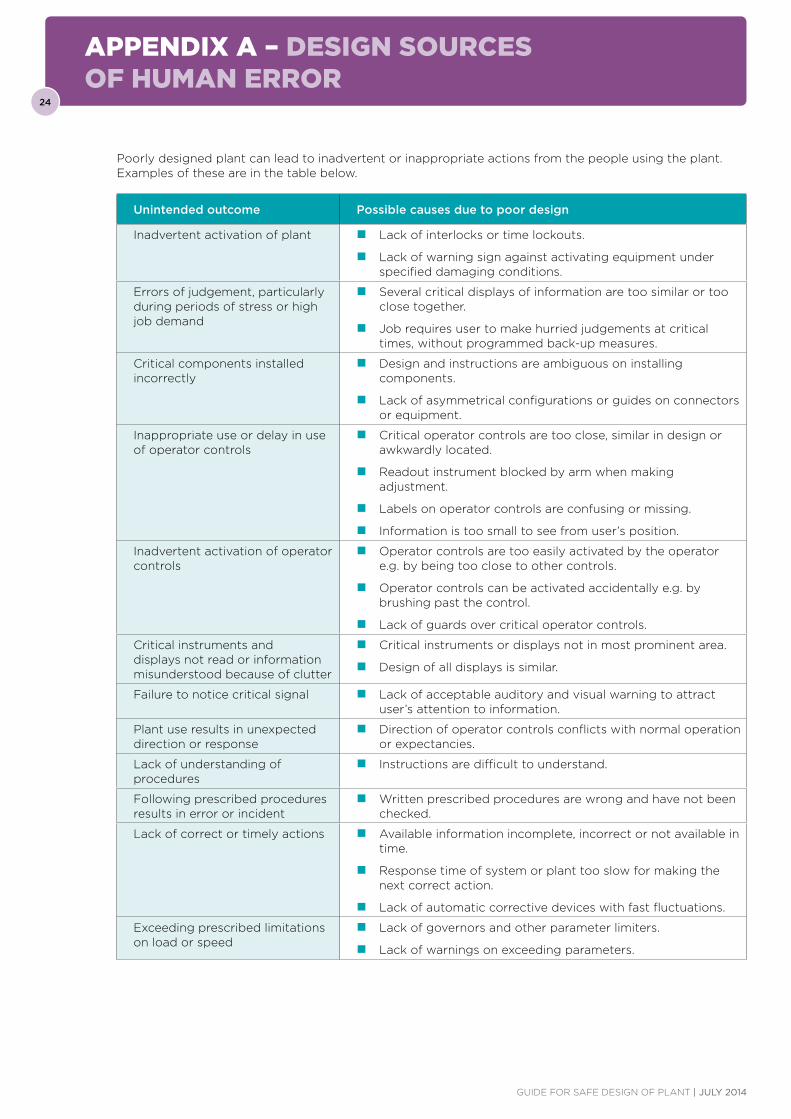
Poorly designed plant can lead to inadvertent or inappropriate actions from the people using the plant. Examples of these are in the table below.
Unintended outcome Possible causes due to poor design
Inadvertent activation of plant � Lack of interlocks or time lockouts.
� Lack of warning sign against activating equipment under specified damaging conditions.
Errors of judgement, particularly during periods of stress or high job demand
� Several critical displays of information are too similar or too close together.
� Job requires user to make hurried judgements at critical times, without programmed back-up measures.
Critical components installed incorrectly
� Design and instructions are ambiguous on installing components.
� Lack of asymmetrical configurations or guides on connectors or equipment.
Inappropriate use or delay in use of operator controls
� Critical operator controls are too close, similar in design or awkwardly located.
� Readout instrument blocked by arm when making adjustment.
� Labels on operator controls are confusing or missing.
� Information is too small to see from user’s position.
Inadvertent activation of operator controls
� Operator controls are too easily activated by the operator e.g. by being too close to other controls.
� Operator controls can be activated accidentally e.g. by brushing past the control.
� Lack of guards over critical operator controls.
Critical instruments and displays not read or information misunderstood because of clutter
� Critical instruments or displays not in most prominent area.
� Design of all displays is similar.
Failure to notice critical signal � Lack of acceptable auditory and visual warning to attract user’s attention to information.
Plant use results in unexpected direction or response
� Direction of operator controls conflicts with normal operation or expectancies.
Lack of understanding of procedures
� Instructions are difficult to understand.
Following prescribed procedures results in error or incident
� Written prescribed procedures are wrong and have not been checked.
Lack of correct or timely actions � Available information incomplete, incorrect or not available in time.
� Response time of system or plant too slow for making the next correct action.
� Lack of automatic corrective devices with fast fluctuations.
Exceeding prescribed limitations on load or speed
� Lack of governors and other parameter limiters.
� Lack of warnings on exceeding parameters.