Embed Size (px)
Citation preview

SANDIA REPORTSAND2017-3386Unlimited ReleasePrinted 07 March 2017
Guide for Cyber Assessment ofIndustrial Control SystemsField Devices
Jason Stamp, Ph.D., Jennifer Stinebaugh, and Daniel Fay, Ph.D.Sandia National Laboratories
Prepared bySandia National LaboratoriesAlbuquerque, New Mexico 87185 and Livermore, California 94550
Sandia National Laboratories is a multi-program laboratory managed and operated bySandia Corporation, a wholly owned subsidiary of Lockheed Martin Corporation, for the U.S.Department of Energy’s National Nuclear Security Administration under contract DE-AC04-94AL85000.
DISTRIBUTION STATEMENT A: Approved for public release: distribution unlimited.

Issued by Sandia National Laboratories, operated for the United States Department of Energyby Sandia Corporation.
NOTICE: This report was prepared as an account of work sponsored by an agency of theUnited States Government. Neither the United States Government, nor any agency thereof,nor any of their employees, nor any of their contractors, subcontractors, or their employees,make any warranty, express or implied, or assume any legal liability or responsibility for theaccuracy, completeness, or usefulness of any information, apparatus, product, or process dis-closed, or represent that its use would not infringe privately owned rights. Reference herein toany specific commercial product, process, or service by trade name, trademark, manufacturer,or otherwise, does not necessarily constitute or imply its endorsement, recommendation, orfavoring by the United States Government, any agency thereof, or any of their contractors orsubcontractors. The views and opinions expressed herein do not necessarily state or reflectthose of the United States Government, any agency thereof, or any of their contractors.
Printed in the United States of America. This report has been reproduced directly from thebest available copy.
Available to DOE and DOE contractors from:
U.S. Department of EnergyOffice of Scientific and Technical InformationP.O. Box 62Oak Ridge, TN 37831
Telephone: (865) 576-8401Facsimile: (865) 576-5728E-Mail: [email protected] ordering: http://www.osti.gov/scitech
Available to the public from:
U.S. Department of CommerceNational Technical Information Service5301 Shawnee RdAlexandria, VA 22312
Telephone: (800) 553-6847Facsimile: (703) 605-6900E-Mail: [email protected] ordering: http://www.ntis.gov/search
DEP
ARTMENT OF ENERGY
• • UN
ITED
STATES OF AM
ERI C
A
2

SAND2017-3386Unlimited Release
Printed 07 March 2017
Guide for Cyber Assessment ofIndustrial Control Systems
Field Devices
Jason Stamp, Ph.D.Special Cyber Initiatives Department
Jennifer StinebaughExecutive Support Division
Daniel Fay, Ph.D.Assurance Tech and Assessments Department
Sandia National LaboratoriesP.O. Box 5800
Albuquerque, NM 87185-1188
Abstract
Programmable logic controllers (PLCs) and other field devices are important components of manyweapons platforms, including vehicles, ships, radar systems, etc. Many have significant cybervulnerabilities that lead to unacceptable risk. Furthermore, common procedures used during Oper-ational Test and Evaluation (OT&E) may unexpectedly lead to unsafe or severe impacts for the fielddevices or the underlying physical process. This document describes an assessment methodologythat addresses vulnerabilities, mitigations, and safe OT&E.
3

Acknowledgements
The authors would like to acknowledge the funding and technical support from the Office of theDirector, Operational Test and Evaluation (DOT&E) for the development of this paper. Also,there were key contributions by other Sandia National Laboratories (SNL) personnel supportingthe analysis, particularly from Mitch Martin, Tricia Schulz, Chris Davis, and Nick Pattengale, andfrom Pacific Northwest National Laboratory (PNNL), especially Chris Bonebrake, Jim Brown, andKaty Bragg.
4

Executive Summary
Industrial control system (ICS) field devices like programmable logic controllers (PLCs) play acritical role in the safe and reliable operation of Department of Defense (DOD) platforms andweapon systems operations. Unfortunately, these sorts of devices are often rife with cyber securityvulnerabilities that can lead to significant risks for mission performance, or even unsafe conditionsduring routine Operational Test and Evaluation (OT&E). The cyber security issues faced by ICSdiffer from typical information technology (IT), and this requires a different and more specificapproach to assess, test, and mitigate ICS vulnerabilities.
In a typical IT system, data confidentiality and integrity are the primary concerns. In an ICS,mission operations, safety, public health, and avoiding equipment damage are the primary con-cerns. ICS devices directly control time critical processes and have little margin for delay. Outagesor interruptions (even something as simple as a reboot) might not be acceptable, and if unplannedcan result in significant risk to mission. Unlike IT system updates or patches, which can be doneusing automated server-based tools and are widely applicable, ICS updates are specific to theequipment vendor.
OT&E on ICS field devices (on deployed platforms, or in high value test rigs) is often a neces-sary requirement, but this causes significant concern within the DOD ICS community. The concernis that implementing routine cyber security measures and testing on active ICS components andsystems may damage the ICS or even underlying physical systems. Of particular concern are ICSfield devices, which encompasses the specialized hardware that covers the boundary between thecyber and physical domains. Examples of field devices include PLCs, electric power relays, remoteterminal units (RTUs), and other embedded devices.
The goals of the Field Device Assessment Methodology (FDAM) are to research and rank fielddevice vulnerabilities to be tested, summarize associated mitigations, and determine cyber testconcerns by summarizing potential OT&E test damage/safety issues. The FDAM primarily sup-ports the cooperative assessment stage of OT&E, although the results can also support adversarialassessments.
This document provides guidance on tools and procedures that have been developed by SandiaNational Laboratories (SNL) that are used to implement the FDAM approach, including an assess-ment framework, quantitative risk calculation, and ranked access/procedure pairs (APPs); these aredescribed in Chapters 2 through 4. The FDAM process itself is presented in Chapters 5 through7 – from initial research and discovery, to standalone lab testing, through to compiling the finalreport.
5

As cyber security testing is inherently complex and detail-oriented, personnel executing theFDAM will generally differing knowledge and experience, and this is difficult to fully documentor simplify into a step by step process. Different testing situations will influence the testing processand its execution; therefore, it is not necessary to follow every step in the document as laid out.
The FDAM is intended to support operational test agencies (OTAs), cyber protection teams(CPTs), and other organizations within DOD that support OT&E on weapons platforms and sys-tems, but it can also be applied to ICS used within DOD installations and other bases, particularlyfor infrastructure support. The Director, Operational Test and Evaluation (DOT&E) FDAM is ap-plicable for mission platforms, which are heavily reliant on ICS, including naval shipboard systems(electrical plant management, machinery control, aircraft launch/recovery, radar, fire control, andothers), advanced ground vehicle management, and aircraft/avionics. The FDAM also supportsa range of DOD assessment requirements [1, 2] and the approach is suitable to varying classifi-cation levels, as application details and close-held government information can be included whendesirable (and useful).
6

Contents
Executive Summary 5
Abbreviations and Acronyms 13
1 Introduction 15
1.1 Overview of the FDAM . . . . . . . . . . . . . . . . . . . . . . . . . . . . . . . . . . . . . . . . . . . . . . . 17
1.2 Applicability of the FDAM . . . . . . . . . . . . . . . . . . . . . . . . . . . . . . . . . . . . . . . . . . . . 18
1.3 Intended FDAM Results . . . . . . . . . . . . . . . . . . . . . . . . . . . . . . . . . . . . . . . . . . . . . . 20
2 Framework for Analyzing ICS Field Devices 21
2.1 Adversary Goals . . . . . . . . . . . . . . . . . . . . . . . . . . . . . . . . . . . . . . . . . . . . . . . . . . . . . 22
2.2 Procedures for Cyber Attack . . . . . . . . . . . . . . . . . . . . . . . . . . . . . . . . . . . . . . . . . . . 23
2.3 Access to the Device Environment . . . . . . . . . . . . . . . . . . . . . . . . . . . . . . . . . . . . . . 25
2.4 Device and System Vulnerabilities . . . . . . . . . . . . . . . . . . . . . . . . . . . . . . . . . . . . . . 28
2.5 Cyber Risk Mitigation . . . . . . . . . . . . . . . . . . . . . . . . . . . . . . . . . . . . . . . . . . . . . . . . 29
3 Applying the Framework to Develop and Prioritize Access/Procedure Pairs 35
3.1 Network Access (A2) and Atypical Stimuli (P4) . . . . . . . . . . . . . . . . . . . . . . . . . . . . 37
3.2 Network Access (A2) and Device Management (P1) . . . . . . . . . . . . . . . . . . . . . . . . 37
3.3 Physical Access (A1) and Atypical Stimuli (P4) . . . . . . . . . . . . . . . . . . . . . . . . . . . . 38
3.4 Physical Access (A1) and Device Management (P1) . . . . . . . . . . . . . . . . . . . . . . . . . 39
3.5 Engineering Workstation Access (A5) and Device Management (P1) . . . . . . . . . . . 40
3.6 Peer Device Access (A4) and Atypical Stimuli (P4) . . . . . . . . . . . . . . . . . . . . . . . . . 40
3.7 Peer Device Access (A4) and Device Management (P1) . . . . . . . . . . . . . . . . . . . . . . 41
3.8 Network Access (A2) and Privileged Operational Relationship (P2) . . . . . . . . . . . . 41
3.9 Network Access (A2) and Device Impersonation (P3) . . . . . . . . . . . . . . . . . . . . . . . 41
7

4 Cyber Risk Quantification 43
4.1 Attack Vector . . . . . . . . . . . . . . . . . . . . . . . . . . . . . . . . . . . . . . . . . . . . . . . . . . . . . . . 45
4.2 Attack Complexity . . . . . . . . . . . . . . . . . . . . . . . . . . . . . . . . . . . . . . . . . . . . . . . . . . . 46
4.3 Privileges Required . . . . . . . . . . . . . . . . . . . . . . . . . . . . . . . . . . . . . . . . . . . . . . . . . . 47
4.4 User Interaction . . . . . . . . . . . . . . . . . . . . . . . . . . . . . . . . . . . . . . . . . . . . . . . . . . . . . 47
4.5 Confidentiality Impact . . . . . . . . . . . . . . . . . . . . . . . . . . . . . . . . . . . . . . . . . . . . . . . . 48
4.6 Integrity Impact . . . . . . . . . . . . . . . . . . . . . . . . . . . . . . . . . . . . . . . . . . . . . . . . . . . . . 49
4.7 Availability Impact . . . . . . . . . . . . . . . . . . . . . . . . . . . . . . . . . . . . . . . . . . . . . . . . . . . 50
5 Literature Review and Device Physical Examination 51
5.1 Literature Review Process . . . . . . . . . . . . . . . . . . . . . . . . . . . . . . . . . . . . . . . . . . . . . 52
5.2 Device Physical Examination . . . . . . . . . . . . . . . . . . . . . . . . . . . . . . . . . . . . . . . . . . 53
5.3 Collating the Results . . . . . . . . . . . . . . . . . . . . . . . . . . . . . . . . . . . . . . . . . . . . . . . . . 55
6 Testing the ICS Device 57
6.1 Test Scoping: Deciding What to Test . . . . . . . . . . . . . . . . . . . . . . . . . . . . . . . . . . . . . 58
6.2 Verification/Characterization Testing . . . . . . . . . . . . . . . . . . . . . . . . . . . . . . . . . . . . . 59
6.3 Exploration Testing . . . . . . . . . . . . . . . . . . . . . . . . . . . . . . . . . . . . . . . . . . . . . . . . . . 63
7 Conclusion: Writing a Device Test Report 65
7.1 Introduction . . . . . . . . . . . . . . . . . . . . . . . . . . . . . . . . . . . . . . . . . . . . . . . . . . . . . . . . 66
7.2 Literature Review and Device Physical Examination . . . . . . . . . . . . . . . . . . . . . . . . 67
7.3 Verification/Characterization Testing . . . . . . . . . . . . . . . . . . . . . . . . . . . . . . . . . . . . . 68
7.4 Exploration Testing . . . . . . . . . . . . . . . . . . . . . . . . . . . . . . . . . . . . . . . . . . . . . . . . . . 70
7.5 Device Report Summary . . . . . . . . . . . . . . . . . . . . . . . . . . . . . . . . . . . . . . . . . . . . . . 70
References 71
8

Appendices
A FDAM Test Scoping Example 73
B Revision History 81
C Contact Information 83
9

List of Tables
3.1 Prioritized APPs with associated goals . . . . . . . . . . . . . . . . . . . . . . . . . . . . . . . . . . . 36
4.1 Qualitative severity rating scale . . . . . . . . . . . . . . . . . . . . . . . . . . . . . . . . . . . . . . . . . 44
4.2 Metric values . . . . . . . . . . . . . . . . . . . . . . . . . . . . . . . . . . . . . . . . . . . . . . . . . . . . . . . 44
4.3 Risk scoring: attack vector . . . . . . . . . . . . . . . . . . . . . . . . . . . . . . . . . . . . . . . . . . . . . 45
4.4 Risk scoring: attack complexity . . . . . . . . . . . . . . . . . . . . . . . . . . . . . . . . . . . . . . . . . 46
4.5 Risk scoring: privileges required . . . . . . . . . . . . . . . . . . . . . . . . . . . . . . . . . . . . . . . . 47
4.6 Risk scoring: user interaction . . . . . . . . . . . . . . . . . . . . . . . . . . . . . . . . . . . . . . . . . . 47
4.7 Risk scoring: confidentiality impact . . . . . . . . . . . . . . . . . . . . . . . . . . . . . . . . . . . . . 48
4.8 Risk scoring: integrity impact . . . . . . . . . . . . . . . . . . . . . . . . . . . . . . . . . . . . . . . . . . 49
4.9 Risk scoring: availability impact . . . . . . . . . . . . . . . . . . . . . . . . . . . . . . . . . . . . . . . . 50
6.1 Vulnerability testing rules based on APPs and risk score . . . . . . . . . . . . . . . . . . . . . 59
A.1 Qualitative severity rating scale . . . . . . . . . . . . . . . . . . . . . . . . . . . . . . . . . . . . . . . . . 73
A.2 Example review and exam vulnerabilities . . . . . . . . . . . . . . . . . . . . . . . . . . . . . . . . . 74
A.3 Testing rules based on APPs and risk . . . . . . . . . . . . . . . . . . . . . . . . . . . . . . . . . . . . 75
A.4 Test decisions for V/C using APPs and test criteria . . . . . . . . . . . . . . . . . . . . . . . . . . 76
A.5 Final vulnerabilities test set . . . . . . . . . . . . . . . . . . . . . . . . . . . . . . . . . . . . . . . . . . . . 77
A.6 Final V/C testing vulnerabilities and mitigations set . . . . . . . . . . . . . . . . . . . . . . . . . 78
A.7 List of vulnerabilities and mitigations discovered in V/C testing . . . . . . . . . . . . . . . 79
A.8 Exploration test decisions using APPs and test criteria . . . . . . . . . . . . . . . . . . . . . . . 79
A.9 Exploratory testing vulnerabilities and mitigations set . . . . . . . . . . . . . . . . . . . . . . . 80
10

Abbreviations and Acronyms
A availability (for A by itself)
A access (for A followed by a number)
APP access/procedure pair
C confidentiality
CANBUS controller area network bus
CP communications processor
CPT cyber protection team
CPU central processing unit
CVE common vulnerabilities and exposures
CVSS Common Vulnerability Scoring System
DOD Department of Defense
DOS denial of service
DOT&E Director, Operational Test and Evaluation
DRAM dynamic random-access memory
EEPROM electrically erasable programmable read-only memory
EM electromagnetic
EW electronic warfare
FDAM Field Device Assessment Methodology
FTP file transfer protocol
G goal (for G followed by a number)
HART highway addressable remote transducer
I integrity
I/O input/output
11
ICS industrial control system
ICS-CERT Industrial Control Systems Cyber Emergency Response Team
IT information technology
JTAG Joint Test Action Group
LED light emitting diode
LOE level of effort
M mitigation (for M followed by a number)
MMC MultiMediaCard
NIST National Institute of Standards and Technology
OPFOR opposing force
OS operating system
OSD Office of the Secretary of Defense
OT operational technology
OTA operational test agency
OT&E Operational Test and Evaluation
P procedure (for P followed by a number)
PCB printed circuit board
PCMCIA Personal Computer Memory Card International Association
PHY physical transceiver
PLC programmable logic controller
PNNL Pacific Northwest National Laboratory
RBAC role-based access control
RE reverse engineering
RF radio frequency
ROE rules of engagement
RTU remote terminal unit
SCADA supervisory control and data acquisition
12

SDRAM synchronous dynamic random-access memory
SERDES serializer/deserializer
SNL Sandia National Laboratories
SoC system-on-a-chip
SRAM static random-access memory
SSH secure shell
TCP Transmission Control Protocol
TCP/IP Transmission Control Protocol/Internet Protocol
US United States
US-CERT United States Computer Emergency Readiness Team
USB universal serial bus
V vulnerability (for V followed by a number)
VME Versa Module Europa
VPN virtual private network
V/C verification/characterization
WAN wide area network
13

14

Chapter 1
Introduction
This document provides an overview of the Field Device Assessment Methodology (FDAM). TheFDAM approach encapsulates the experience that has been developed over many years by ana-lysts at Sandia National Laboratories (SNL) to provide a safe, economical, and efficient approachthat can be used to analyze and test potential mitigations to industrial control system (ICS) cybersecurity vulnerabilities, both in laboratory testing and later in operational settings.
Over the last 20 years there has been increasing recognition of cyber vulnerabilities in ICS,starting with concerns relating to United States (US) critical infrastructure. Initially, ICS vendorsdeveloped highly specialized technology that had a severely constrained operating envelope (verylow bitrate networks, analog signaling, and minimal software). However, the ICS industry hasincreasingly adopted conventional information technology (IT) capabilities and approaches; forexample, ICS control center software is installed on conventional (often Windows-based) comput-ers, and the ubiquitous Transmission Control Protocol/Internet Protocol (TCP/IP) protocol stacknow supports a lot of ICS networking. The adoption of IT technologies for increased ICS ca-pabilities has led to security problems since ICS and IT systems are designed and implementeddifferently. Technologies borrowed from IT systems sometimes include their own vulnerabilities;in an IT environment, regular patching is expected and provides mitigation, but ICS owners areoften reluctant to change a fielded system and therefore rarely apply patches. This leads to manyICS having known vulnerabilities that are not fixed once they become known, which stresses theimportance of operational testing for systems or platforms that utilize ICS.
A second challenge is the lack of a strong cyber focus on the part of the ICS vendor andintegrator communities. Since operational availability is the key motivating factor, decisions favorreliability over security. For example, in the design stage, hardcoded vendor backdoor passwordsmay facilitate troubleshooting (although awareness of this as a problem is improving) and ICSsoftware packages run with highest privileges to avoid any potential problems caused by incorrectpermissions. Some ICS networking protocols are extraordinarily permissive, up to allowing directmemory access to facilitate simple, reliable control and troubleshooting. Moreover, ICS networksrarely include network defense-in-depth, because this can introduce additional communicationdelays and add more potential points of failure. Furthermore, ICS component designs often assumea rigidly bounded set of operational conditions that are expected for any deployment. As a result,implementations of key services on ICS devices may not support reasonable error checking andcapture. Unexpected IT network traffic (like port/device scans, broadcast traffic, or malformedpackets) could lead to interruptions or crashes. Potential device fragility limits the techniquesavailable to monitor and secure ICS.
15

According to an Office of the Secretary of Defense (OSD) memorandum regarding “Proceduresfor Operational Test and Evaluation of Cybersecurity in Acquisition Programs,” operational testagencies (OTAs) will “include cyber threats... with the same rigor as other threats” [3]. Thepurpose of cyber security operational test and evaluation is to evaluate the ability of a unit equippedwith a system to support assigned missions in the expected environment. The “system” in thiscase is considered to encompass hardware, software, user operators, etc. This memorandum alsospecifies the procedures to be used for testing oversight systems. The purpose of this documentis to introduce a FDAM that parallels (with some differences due to the focus on ICS hardwareand not the entire system) the procedures suggested in the memorandum. The FDAM approachis not intended to cover the entire oversight system as referenced in the memorandum; rather, itexplains the procedures necessary to evaluate the ICS hardware devices. This focused approach onthe hardware subset of the system is warranted because ICS field devices face very different issuesthan IT systems, and the risks associated with ICS cyber vulnerabilities can be significant.
Due to these issues, there is significant concern within the Department of Defense (DOD) ICScommunity that routine cyber security measures that actively engage components and systemsmay prove damaging to the ICS or even underlying physical systems when testing is performed onoperational systems or high-value test rigs. The effects that are of concern include:
• Unexpected or unpredictable physical system behavior
• Damage to physical system components
• Denial of service (DOS) for local automated or manual control
• DOS to supervisory control
• Unrecoverable (or nearly so) faults for field devices
The FDAM has been developed to summarize vulnerabilities, prioritize risk, evaluate miti-gation measures, and develop measures for safe Operational Test and Evaluation (OT&E). TheFDAM manages the above effects of concern by developing insight and limitations for field de-vice cyber security issues in a lab setting before performing tests or implementing cyber securitymitigations on operational devices.
16

1.1 Overview of the FDAM
A high level overview of the FDAM approach is listed below, with associated chapter numberswhere applicable:
• Literature review and device physical examination (Chapter 5)
• Verification/characterization (V/C) testing (Chapter 6)
• Exploration testing (Chapter 6)
• FDAM summary (Chapter 7)
– Conclusions
– Recommendations
The FDAM is a process-oriented encapsulation of experience from decades of work by analystsat SNL. The methodology should provide a safe, economical, and efficient approach to analyzeand test potential mitigations to ICS field device vulnerabilities, both in laboratory testing andoperational settings.
It should be noted that cyber security is inherently complex and detail-oriented. The peoplethat perform testing and analysis often have a wealth of knowledge and experience that in somecases cannot be documented or simplified into a step-by-step process. The FDAM tries to be asthorough as possible, but it should be noted that in every testing situation, the experience andknowledge of the testers may influence part or all of the process. For example, a tester that isintimately familiar with supervisory control and data acquisition (SCADA) systems and has hadyears of experience in the ICS management field might choose to do literature review and vulner-ability scoring concurrently with lab testing. A person with limited experience might take a moreconservative, methodical approach and follow the procedures presented here to the letter. The goalof the approach is to help testers optimize assessment scoping in order to ensure efficiency, safety,and highest return on testing approaches.
Several conceptual frameworks and tools have been developed that are essential to understand-ing the FDAM approach. These are described prior to the actual procedures in order to to providea necessary foundation and ground subsequent discussions. These tools, described in Chapters 2-4include:
• Cyber risk framework
• Prioritized access/procedure pairs
• Vulnerability risk calculation
17

The FDAM activities are organized according to a cyber risk framework, comprised of fivecategories (Chapter 2). Each of these five category consists of several components, which are usedto prioritize the cyber analysis and testing:
• Goals – what is the adversary trying to achieve
• Procedures – what the adversary is doing during cyber attack
• Access – the avenue to the device environment
• Vulnerabilities - includes both device and system vulnerabilities
• Mitigations - cyber and physical, for defend/detect/manage
A key concept of the FDAM approach is the introduction of prioritized APPs developed toensure optimal testing scenarios are chosen (refer to Chapter 3). These APPs, combined withthe risk ranking calculation, allow the tester to optimally select the vulnerabilities to be tested bynarrowing down the scope of the testing landscape, ensuring the highest degree of improved cybersecurity without compromising ICS performance or safety. Each APP also includes examples oftests and potential (or likely) vulnerabilities.
The vulnerability risk calculation has been transposed from an IT-based Common VulnerabilityScoring System (CVSS) system to be more applicable to ICS systems (Chapter 4). This calculationassesses the risk associated with vulnerabilities uncovered by the literature review and research,and is used as a guideline (in conjunction with the APPs described above)to optimally select whatis to be tested. If a particular vulnerability has a low risk score, but could be very difficult to testor if mitigation is onerous, it might be removed from the assessment. Conversely, if a vulnerabil-ity carries with it a high risk score, and the mitigation approach is simple, it should strongly beconsidered for further testing. An example of this selection process is given in Appendix A.
1.2 Applicability of the FDAM
While high capability threats are within scope (up to and including advanced adversaries), manyICS implementations are vulnerable to much lower-capability adversaries and techniques. Simplervulnerabilities that require lower level of effort (LOE) are of higher concern, as are ones that havea greater effect on device operations (which could affect the underlying physical process). Thedegree of difficulty for detection or prevention of the vulnerability is also a factor. Furthermore,to best analyze ICS cyber security, some level of opportunity (in the form of adversary access andcapability) must be assumed. Therefore, access denial for ICS field devices will attenuate risks andcomplement mitigations described in a completed FDAM assessment report. Assuming reasonableaccess is also most attuned for understanding operational test safety concerns.
18

The DOD has a mature and proven approach for cyber security [4, 5] for networking andhigher level system support environments. The FDAM approach instead focuses on mitigatingrisks specifically for fielded ICS devices, which in general have a less mature security frameworkgiven the motivation and necessity to keep the devices running. Thus, the FDAM approach ensuresthat mitigation efforts considered will:
1. Preserve system operation (to best support mission performance)
2. Prevent damage or degradation to associated physical systems
3. Deny attractive information from an ICS to an adversary
In general, the FDAM approach should be amenable to different deployment situations, including:
1. A given component in a specific application (e.g. a water pump control system)
2. A given component in a typical application (e.g. machinery control)
3. A given component in any application
The application may help characterize the technical configuration of the component or ICS, al-though some variability is always expected given refresh cycles for weapons platforms. Of course,less specificity may enable more generally useful conclusions; however, as specificity increasesthere is more opportunity to understand vulnerabilities and mitigations (as an example, possiblephysical domain mitigation steps that guard the controlled process against malfunctioning PLC).In the Director, Operational Test and Evaluation (DOT&E) process for understanding cyber risk,the results from analyses derived from this methodology will inform future structured cyber as-sessments [3] by providing an important foundational characterization.
The FDAM is focused on mission platforms, which are heavily reliant on ICS. Examples in-clude many naval shipboard systems (electrical plant management, machinery control, aircraftlaunch/recovery, radar, fire control, and others), advanced ground vehicle management (enginecontrol/optimization, CANBUS-based networks, etc.), and aircraft/avionics (often based on VMEand 1553 bus). Although the FDAM is intended to support OTAs, cyber protection teams (CPTs),and other organizations within DOD that support OT&E on weapons platforms and systems, butit can also be applied to ICS used within DOD installations and other bases, particularly for in-frastructure support (like electric power, water, physical security,lighting systems for flight lines,radar, water treatment, access denial systems, heating/cooling plants, etc).
19

1.3 Intended FDAM Results
The FDAM supports a range of DOD assessment requirements [1, 2] and the approach is suit-able to varying classification levels, as application details and close-held government informationcan be included when desirable (and useful). The information gathered by using the FDAM ap-proach should be put into a final report (see Chapter 7) that summarizes the vulnerabilities andmitigations that are to be lab tested (see Appendix A), results of the testing, and recommendationsregarding potential OT&E test damage/safety concerns and whether potential mitigations shouldbe implemented on an operational systems.
20

Chapter 2
Framework for Analyzing ICS Field Devices
The FDAM is based on a generalized framework which has been developed to capture the cybersecurity elements necessary to successfully use the approach. There are five categories for consid-eration – adversary goals (G), procedures for cyber attack (P); access to the device environment(A); device and system vulnerabilities (V); and cyber/physical mitigations (M). These categories,with the subcomponents of each, are listed below:
• Adversary Goals (G)
– G1: Change behavior
– G2; Misrepresent state
– G3: Obtain or change data
– G4: Deny operation
– G5: Use as intermediate attack platform
• Procedures for Cyber Attack (P)
– P1: Achieve device management access
– P2: Gain privileged operational relationship
– P3: Impersonate the device
– P4: Affect device operation via atypical stimuli
• Access to the Device Environment (A)
– A1: Physical
– A2: Network
– A3: Secondary
– A4: Peer device
– A5: Engineering workstation
– A6: Supply chain
21

• Device and System Vulnerabilities (V)
– V1: Common problems/networking and communications
– V2: Common problems/architecture and management
– V3: Equipment-specific problems
– V4: Context- or application-specific problems
• Cyber and Physical Mitigations (M)
– M1: Defend – take actions that prevent unwanted access
– M2: Detect – monitor for unauthorized system access attempts
– M3: Manage – react appropriately to incidents and ensure successful recovery
Goals are achieved by procedures, which in turn are made possible via access, and involve theexploitation of vulnerabilities to be successful. Vulnerabilities are best understood in the contextof an adversaries’ goals or intent, which may be specific or general to a desired scenario – this isthe threat. Cyber risks can be denied or attenuated by proper mitigation strategies (which couldencompass safeguards that limit the risk – for example, a purely mechanical pressure relief valvewould not allow an embedded device to catastrophically over-pressurize a pipe).
Each of the five categories is described in detail below. Note that in the access and procedurecategories, the descriptions include a notation that describes its prioritization within the FDAM(the overall framework itself is general and applicable to many assessment situations, and so thenotation is necessary to describe its application for this work). This prioritization is key part of theFDAM testing approach, and will be described in detail in Chapter 3 as prioritized APPs.
2.1 Adversary Goals
Goals for cyber attacks against embedded devices in ICS generally fall into five categories. Anadversary will seek one or more goals to achieve a desired effect in the underlying physical ar-chitecture (weapons systems, electric supply, machinery control, oil/gas pipelines, manufacturing,building automation, etc.).
• Goal G1 – Change behavior:Changing the control settings or logic can lead to behavior that is advantageous to an ad-versary. In extreme cases, this could cause or contribute to equipment damage, dangeroushazards, or systems degradation/failure.
• Goal G2 – Misrepresent state:Embedded devices form the boundary between control and the physical process. Vulnerabil-ities might facilitate the device misrepresenting the process state (or its own), either directly(the device itself is misrepresenting) or indirectly (the device can be easily impersonated).
22

• Goal G3 – Obtain or change data:Any embedded device may be more or less amenable to reporting potentially sensitive dataabout itself or the underlying process to unauthorized actors, or toggling control based oncorrectly-formatted protocol directions.
• Goal G4 – Deny operation:Embedded devices are almost always expected to have very high uptime, particularly to man-age potentially dangerous physical processes. Therefore, a short-term loss of functionality– even partial – could be important. Straightforward vulnerabilities can permanently disablesome devices. Note that the denied operations are being analyzed from the perspective ofthe field device itself; therefore, denial of communications external to the device would bean example of a procedure that would be out-of-scope.
• Goal G5 – Use as intermediate attack platform:An adversary can theoretically use any computing device as a network or systems beachheadfor further malevolent activities. This will usually take the form of a high-privilege interac-tive session for the adversary, with the download and hosting of additional software toolsdesirable. Very often, the architecture of embedded devices makes this goal unlikely, but itremains reasonable for some scenarios – particularly if the embedded device is leveragingmore conventional hardware/software or has interesting connectivity.
Individual analysis for the targeted equipment will determine the likelihood of its susceptibil-ity to these goals. Risk will depend on the chosen attack procedures, the access available to anadversary, and vulnerabilities/mitigations for the equipment.
2.2 Procedures for Cyber Attack
An adversary has several generalized operations that can support realization of their goals. Pro-cedures can be thought of as the net results of overall scenarios that adversarial manipulation ofthe targeted equipment (a series of attack steps). For this category and the next (“access”), thereis a descriptor in each category that describes the analysis priority for a FDAM assessment (“forthe purposes of FDAM, this is listed as Priority #X”). This prioritization is key part of the testingapproach, and will be used as a foundation for the discussions in Chapter 3.
23

• Procedure P1: Achieve device management accessEmbedded devices can be thought of as running one or more software processes subject toconfiguration parameters. In most devices, both software and parameters are configurableand reprogrammable remotely, and nearly all support modification via the device’s serialport or local interface. Typical configuration parameters include management-specific infor-mation, like networking addresses, accounts (to the extent that the device supports them),logging frequency and parameters, etc. Other configuration data affects the equipment’scontrol and measurement of physical data, like control setpoints, measurement intervals andscaling, ladder logic, etc. Device firmware encompasses all software outside of configura-tion, including boot loaders, operating systems, software, and other data. Note that, in amodular device, each component can contain configuration and firmware. Modifying thedevice’s behavior could allow an adversary to achieve any goal (although G5 might be dif-ficult if malware or tools are not available for the targeted equipment’s architecture). Thedevice hardware may also be changed to suit an adversary. Given the poor state of foren-sics for many existing embedded systems, P1-type scenarios could easily lend themselvesto minimal probability of detection or attribution and because embedded devices have longoperational deployments, adversary-driven changes in configuration could have a long-termpresence.
For the purposes of FDAM, procedure P1 is included as Priority #2. This clearly has thepotential for extreme impacts to ICS devices and underlying physical systems.
• Procedure P2: Gain privileged operational relationshipEmbedded devices often have weak or nonexistent capabilities to authenticate their peersin operational relationships. As an example, a PLC running the Modbus protocol will replywith current data to any well-formed data request that accesses a configured data register, andwould toggle process control similarly. Therefore, depending on the situation and access, anadversary could easily gain valuable data and potentially affect processes (G3) by injectingcontrol data. This might involve accessing existing peer devices, adding customized hard-ware to the network, or simply injecting network traffic. The ability to view device trafficon a network could allow for unauthorized access to data being sent to or from an embed-ded device (depending on the protocols and safeguards used), which is a type of privilegedrelationship.
For the purposes of FDAM, procedure P2 is included as Priority #3. The unsecured natureof automation protocols used by ICS devices lead to the likelihood than unauthorized partiesmay issue false but authentic-looking requests for data or control, to whatever extent allowedby the device configuration. This is of lower priority for additional analysis because of itsstraightforward nature, and would only be investigated in depth if there were some uniquerisks or technical details (although it clearly can have significant effects on the ICS andunderlying physical systems).
24
• Procedure P3: Impersonate the deviceThe scenario described in P2 above also extends to the possibility of an attacker providingor consuming data in place of a targeted piece of equipment. The authentic data messagingfor the targeted device could be blocked, changed, or ignored depending on the adversary’sneeds.
For the purposes of FDAM, procedure P3 is included as Priority #4. Impersonating the ICSdevice to peer devices or supervisory control is also straightforward, similar in nature togaining a privileged operational relationship (P2). Therefore, this is also a relatively lowpriority compared to other procedures.
• Procedure P4: Affect device operation via atypical stimuliThis type of procedure covers tactics not previously mentioned. The critical distinction forthis procedure is that all “atypical stimuli” are outside of the on the intended administrationor operations of the field device once deployed. Examples would include DOS attacks, sus-ceptibility to radio frequency (RF) that affects operation or management, flaws in protocolor server implementations that could crash the device, adding unauthorized hardware to thesystem, leveraging debugging capabilities left over from the device development, etc. An-other example: affecting the device programming using the vendor’s configuration softwareto achieve goal G1 is an example of procedure P1, but leveraging a flaw in the device’snetwork stack to overwrite firmware via a network connection is within procedure P4.
For the purposes of FDAM, procedure P4 is included as Priority #1. Although achievingdevice management access conventionally (P1) has more degrees of mapping with respectto goals, affecting device operation via atypical stimuli (P4) is a slightly higher priority forinvestigation because of its associations with inadvertent effects to the device (both changingbehavior and denying operation – G1 and G4 respectively). Potential fragility or mistakes inICS network interface design, implementation, or configuration may lead to significant im-pacts to the device from minimal stimuli, like aggressive networks scans or small sequencesof network traffic from attackers. Again, atypical stimuli includes any attacks outside of thenormal operational envelope or management via vendor-approved approaches.
2.3 Access to the Device Environment
Access allows the potential execution of steps in one or more selected procedures. Access repre-sents a fundamental requirement for any planned procedure and, if unavailable, would negate thefeasibility of even attempting some procedures. However, access can be gained in many differentways over diverse timeframes. As with the “Procedures” section, there is a descriptor describingthe priority of the access for the FDAM analysis. This prioritization will support developments inChapter 3.
25

• Access A1 – PhysicalPhysical access refers to an adversary having the opportunity to touch the device. This af-fords opportunities to change hardware or access non-networked communication ports. Thelatter may be particularly sensitive. Many embedded devices include two primary types ofcommunications/networking interfaces; the first is for interacting with other system oper-ational elements (such as servers in a control center or other embedded devices) for dataexchange and control, and the second is often a high-privilege connection used for deviceconfiguration. (Often the functions of the second are replicated on the first for convenience,and in some cases there is only a single interface for configuration and operations.) However,if there is a dedicated configuration interface, then this represents a potentially attractive op-portunity for an adversary if it can be physically accessed, because it typically has the highestprivilege levels available. If there are authentication challenges, these can be often defeatedby jumpers or other physical interfaces on the equipment. An adversary could also leveragephysical access to introduce additional equipment, either in the local network, on a configu-ration interface, within the embedded device itself, or added to a modular chassis (like manyPLCs have). These can provide varying opportunities for procedures with low potential fordetection (depending on the site’s configuration control and monitoring scheme). Physicalaccess can also easily affect device configuration if the firmware is stored on removable me-dia. Another particularly insidious type of access would be to achieve net physical accessusing social engineering vectors (like the classic case of the USB drive in the parking lot).Similarly, an adversary could game operators to manipulate ICS equipment to affect a num-ber of procedures and achieve goals. Many physical access avenues could be very persistentand stealthy.
For the purposes of FDAM, access A1 is listed as Priority #2. Many severe attacks arepossible given this level of access. The focus will be on achieving device management access(P1) and causing atypical stimuli (P4); privileged relationships (P2) and impersonating thedevice (P3) are not considered.
• Access A2 – NetworkEmbedded devices are very often networked via their operational interfaces to participate incontrol with peer or remote systems. Networks can be based on legacy serial technologyor modern systems like Ethernet and TCP/IP. Local access would be network or commu-nications access to the equipment with physical proximity. Typically, this will involve lessmonitoring given the potential for physical access controls that are usually presumed to be ef-fective. Remote network access would be from physically distant systems over a permanentdata connection, like through an ICS wide area network (WAN) or the cloud, and usuallyincludes greater monitoring and lower bandwidth than local.
For the purposes of FDAM, access A2 is listed as Priority #1. The network avenue haslarge force multiplier for adversaries and enables stealthy remote attack. Also, the DOD isconcerned about potential CPT or opposing force (OPFOR) network auditing and testingwhich could apply significant cyber stress to ICSs devices. Depending on configurations,all procedures are likely feasible; however, gaining a privileged operational relationship(P2) and impersonating the device (P3) have been regularly demonstrated and are of lowerpriority barring some key differentiating factors for the equipment or situations under test.
26
• Access A3 – Secondary communicationPermanent or periodic remote access can be intended for the equipment-owning entity togather data or manage configuration, or could be used via trusted partners like outsourcedtechnical management or vendors (many of which often require highly privileged access totheir equipment). This is separate from continuous network access (A2), in that if both A2and A3 are present, they are on different networks with different technology and distinctopportunities for adversaries. Often the secondary access will apply to a device’s dedicatedconfiguration (physical) port.
For the purposes of FDAM, this access avenue not in scope. The FDAM is focused on de-vices, and data about deployment patterns (which would describe secondary access capabil-ities) is likely absent. Therefore, it is unclear what opportunities there would be for remotenetwork access to device configuration ports. Subsequent analysis can consider relevantanalysis using physical access (A1) to inform risk from A3.
• Access A4 – Peer deviceAn adversary can access the functionality on a targeted device by successfully gaining privi-leges on a peer device, and then exploit the existing trusted data relationships that support theoperations of the operational technology (OT) or ICS system. This would be a straightfor-ward way to execute scenarios that depend on P2 (privileged operational relationship). Thismay or may not allow for additional attack opportunities compared to A2 (network access).
For the purposes of FDAM, access A4 is listed as priority #4. Since the analyst often does nothave comprehensive insight into deployment patterns, and the focus is on device-level con-cerns, this access approach is included only as they relate to designated remote input/output(I/O) or coordinated control architectures for the field device under test. The best approachfor analysis will be to assume physical access to the peer devices or slave I/O (but not to themaster field device itself); this assumption may be reconsidered in light of device usage andenvironment if that information is available.
• Access A5 – Engineering workstationAs noted in the “Procedures” discussion, unauthorized device management is a key problemfor embedded systems. One extremely attractive access opportunity would therefore be viathe platform that is normally used to manage and configure the targeted equipment (typicallycalled the engineering workstation – one or more computing platforms used by techniciansfor authorized configuration control of embedded systems). Either the management softwareitself or other hardware/software elements of the platform could be targeted. This is a type oflifecycle access for the embedded device given the engineering workstation’s key role overthe deployment history for embedded systems.
For the purposes of FDAM, access A5 is listed as priority #3. This vector applies only togaining configuration access (P1), and is concerned with possible effects on the PLC givenattacks against the authorized copy of the device management software, assuming they areconnected at some point.
27
• Access A6 – Supply chain
Another interesting avenue for access is to consider the possibility that an adversary has af-fected the embedded devices’ hardware or software as it was being developed or sourced.Trojan code or modified silicon may require very high investments to achieve, but for certainclasses of adversaries the possibilities are reasonable. Another avenue for access in this cat-egory involves an adversary affecting the supply chain for product updates, particularly forfirmware. Although OT and ICS devices are rarely updated or patched by current practice,there appears to be more acceptance coming for field updates to embedded devices. Underthose conditions, Trojan code may be introduced into systems for later use. Also, many ven-dors retain privileged access via presumed private communications as a condition of theirequipment sale, and those channels present attractive targets for adversaries.
For the purposes of FDAM, this is not in scope, given all of the other vulnerabilities for ICSdevices. However, it is relevant for an advanced threat and should be considered separatelyas needed. Also, the scope of these assessments does not include information regardingintended vendor patch plans for DOD platforms (for either the device or its configurationsoftware), which is an important consideration for this access approach.
2.4 Device and System Vulnerabilities
For the planned analysis, consideration for vulnerabilities is needed to understand the potentialrisks to operations from adversary access to embedded systems. Often, embedded systems – par-ticularly for ICS – are susceptible to classes of common vulnerabilities based on the technologyspace and the particular application. These common problems are investigated for the equipmentbeing analyzed within the categories shown. Other vulnerabilities may be specific to proprietarydesign characteristics or implementation flaws, and those can be subcategorized into “known”(publicly available information) or “close-held” (known only to small audiences, like the manufac-turer, user groups, or government). Lastly, specific information about the device within the targetcontext may illuminate important vulnerabilities.
• Vulnerabilities V1 – Common problems/networking and communications
Vulnerabilities in this category relate to services that are supported by the embedded equip-ment that are necessary to its function within common ICS or OT environments. Due tolegacy development focus solely on availability, protocols used by embedded devices lacksecurity services, and this is not a fault particular to any device.
• Vulnerabilities V2 – Common problems/architecture and management
These types of vulnerabilities relate to the devices themselves, and the way that they are builtand operated according to expectations within an established industry. An example for thiscategory would be the lack of account-based access; although this would be an attractivesecurity feature for role-based access control (RBAC), it is simply not a value-added featurewithin the ICS market.
28

• Vulnerabilities V3 – Equipment-specific problemsThis category of vulnerabilities includes those from the design or implementation of thedevice or equipment. There are two subcategories: well-known problems (information isavailable publicly) and closely-held problems (known only to limited groups or within thegovernment). There are three primary sources for known vulnerabilities: information fromthe manufacturer, vulnerability reporting authorities like Industrial Control Systems CyberEmergency Response Team (ICS-CERT), and relevant user communities including oneswithin government. While equipment-specific close-held problems may range from sim-plistic to extraordinarily sensitive, they are enormously useful information for this sort ofcyber analysis.
• Vulnerabilities V4 – Context- or application-specific problemsFinally, the device vulnerabilities can be highlighted by considering the actual applicationor deployment environment. This would be particularly useful to better understand the dis-cussion of common vulnerabilities, and the existence of specific vulnerabilities within thespecific context (i.e. a known software patch level would clearly settle any issue of specificvulnerabilities being present).
2.5 Cyber Risk Mitigation
Mitigations are a key focus for FDAM. However, they are often less emphasized during deviceanalysis than vulnerability discovery. Therefore, their introduction is somewhat more detailedthan the prior framework elements. As described previously, mitigations in the FDAM frameworkare categorized as follows:
• M1: Defend vulnerabilities (reduce exposure)
• M2: Detect attacks (monitor and alarm)
• M3: Manage incidents (attenuate impacts and recover)
It is important to note that in for the purposes of this analysis, mitigations do not refer to ac-cess denial, which is a separate category of countermeasures, and an area where DOD alreadyhas numerous policies and procedures. Access denial will certainly help to manage risk. Miti-gations might be commonly applied either to manage common vulnerabilities via cyber controls(an example of this might be configuration monitoring) or to guard against physical effects viaphysical controls (like pressure relief valves or fuses, which are not attackable via cyber means butcould lead to extended equipment outages). Mitigations may be specific to an ICS or a particularapplication or context.
29

Some mitigations, particularly those in M3, can be best analyzed by considering the actualdeployment environment. An example could be an electrical fuse in a power system, where anembedded device (a relay) has the primary responsibility for detecting and clearing short circuits,but in the event of relay failure the fuse will blow. Preferably, the short circuit is managed by theembedded device, because it allows for easier restoration of service (perhaps recloser control for atransient issue) compared to needing to dispatch a crew to replace the fuse. However, the potentialoverall effect is greatly reduced by adding a fuse, instead of an adversary compelling relays tocompletely ignore a fault and leading to possible damage and safety impact.
2.5.1 M1 – Defend
Vulnerabilities can be defended by deploying compensatory measures: configuration access shouldbe logged and monitored by additional overhead software; firewalls can be used to create ICS en-claves and defend against abnormal networking traffic; unauthenticated open protocols for com-munication and substandard configuration authentication can be protected; and jumpers to resetpasswords can be physically protected. However, the reality of ICS are that they are designed forreliability, and to date poor security is not seen as a force that could reduce reliability. Unfortu-nately, this makes the addition of security devices that add possible failures an unlikely option,although the balance between greater numbers of failures caused by non-adversarial stimuli versusthe actual reliability of an unprotected ICS should be considered.
The nature of ICS supports a whitelisting approach, which starts with effective characterizationof allowed network communications. There are two major options to consider when consideringdefensive mitigation strategy:
• Blocking unallowable types of activity (perhaps based on network protocols)
• Blocking unallowable types of activity and also unreasonable settings or data within allowedactivities
The former is relatively straightforward to implement, while the latter (a more behavioral ap-proach) is more challenging, but provides better protection. Consider a system using Modbus/TCPfor communications. There may be attacks that attempt to change setpoints outside allowable sys-tem bounds (which can effect the capabilities of the physical process being controlled, or might beassociated with expectations based on current operations). R&D efforts suggest that machine learn-ing techniques for behavioral monitoring are feasible and useful (although false positives would bea threat to impact legitimate operation).
Alternatively, cyber vulnerabilities can be left in place, with some potential issues managedby physical devices. Locked cabinets or physical barriers can help protect jumper settings andremovable memory from tampering and limit RF or EM exposure. Unfortunately, strong physicalprotections may be compromised by poorly considered convenience features. An example wouldbe a PLC locked within a cabinet, but with the device’s serial configuration port extended outsideof the enclosure via a cable.
30

Depending on the specific ICS device, there might be both well-known and closely-held miti-gations, although mitigation steps are often less sensitive than vulnerabilities. Equipment-specificmitigations could be cyber (using vendor-specific security services) or physical (using key-basedrun/program selectors to limit device reconfiguration opportunities – assuming they cannot be by-passed via software, and this is often the case). Another vendor specific mitigation is to ensurethat all patching and updates are in place for specific equipment. However, unlike the patching /update approach used in IT, this might not happen in ICS systems due to downtime associated withimplementation and testing/recertification necessary to bring the system back to operational use.However, a patching / update approach is vital to ICS security, and should be strongly considered,(as long as business/warranty issues are adequately addressed). Careful planning (and possibletesting) can ensure patching is done with minimal effects on the system.
Other opportunities for defense include leveraging vendor-supplied security features to thegreatest extent allowed by the device’s application. Examples include:
• Configuration authentication procedures (which often have significant weaknesses)
• Network encryption or authentication (granted, this is unlikely to be supported by ICS de-vices)
• Setting read-only permissions (possibly using physical settings, although these can some-times be circumvented via cyber attack)
2.5.2 M2 – Detect
Given the reluctance of ICS stakeholders for potentially degrading reliability by inserting com-ponents to defend systems, attack/incident detection is the key opportunity to reduce cyber risk.Detection is especially attractive if it is accomplished by sensors that unobtrusively monitor sig-nals without adding security equipment in-line with systems and operational data flows.
Monitoring can be categorized into the same two major options from the defense discussion.Clearly, any communications protocols that are outside of the narrowly defined allowed set areevidence of misoperation and potentially a cyber intrusion. However, the behavioral model allowsstronger detection. As an example, consider network traffic associated with remote configurationof a PLC. Although this may be necessary to the proper functioning and administration of a sys-tem, a traffic signature showing an active configuration session that is outside normal maintenanceintervals would be cause for concern. Monitoring for reasonable setpoints along the lines of theM1 discussion for defense would also be very useful.
31

Because of their recognized importance, ICS field devices may include some state-of-healthmonitoring that could detect cyber attack. Also, tracking device configuration is an excellent de-fense, particularly given the small amounts of memory in typical field devices. For the majorityof devices, very little (if any) change for most of the memory space (except operational data reg-isters) is expected when the device is operating normally. However, the great range of variationin the architecture of field devices will require customization for any configuration monitoringcountermeasures.
Another opportunity is independent cyber monitoring within the device. If the component ismodular (with a backplane) or has reasonably accessible signal buses, a monitoring device listento the conversations between the component’s constituent modules. Such devices are under activedevelopment [6]. Because of the granularity in communications, a backplane/bus monitor canuniquely observe behavior of the control system independent of the processor and alert when thesystem is not operating within a specifically defined manner defined by whitelisting and behavioralheuristics. Because it alerts on effects of an attack in progress, and not on signatures of priorattacks, countermeasures like backplane or bus monitoring can detect zero-day exploits [7].
The concepts that support the backplane/bus monitoring approach also can be applied on thephysical process side of the ICS field device. This may be realized using a second, independentsystem to monitor the protected device’s output signals to ensure they are suitable for the processand context. However, this is far more resource intensive than a backplane/bus monitor approach,which itself is only one step behind the analog I/O equipment within the device.
Physical security monitoring is complementary to defense measures. Countermeasures likecabinet and access door alarms are almost always good suggestions for mitigation. In contrastwith IT systems, early R&D results for ICS suggest that monitoring power draw for components (aphysical signature) may be a reliable indicator of off-nominal operation that potentially indicatesan attack) [8].
2.5.3 M3 – Manage
Cyber attacks against ICS can cause damage to the physical processes being monitored and con-trolled. Defense and detection based mitigations (M1 and M2) that prevent such damage are pre-ferred but may be infeasible or unreasonable, and so mitigations intended to manage incidentsoften play an important and necessary role. Mitigations in this category can minimize impact tothe physical processes and aid in efficient and safe device recovery in order to restore both local andsupervisory functionality while preserving needed forensic indicators. Device recovery can occurover varying time frames and require varying levels of administrative intervention (in ascendingorder of impact to ICS operations):
32

• Automatic: the device restores itself to operational status after an error condition is detected
• Remote: a qualified admin can restore the device
• Local: qualified admins and/or technicians require physical access to repair/restore the de-vice
Given these parameters, hierarchies of recovery can be described (again, in ascending order ofimpact to operations):
• Automatic self-recovery with short, acceptable delay
• Restore remotely with quick procedure (e.g. toggle a setting)
• Restore remotely with involved procedure (e.g. reload configuration/firmware)
• Restore locally with quick procedure (e.g. rotate key without reset, power toggle)
• Restore locally with involved procedure (e.g. reload configuration/firmware)
• Partially or completely unrecoverable (replace hardware and restore firmware)
Some equipment includes watchdog timers, either in software or hardware, which can monitordevice operation and restore/restart critical components if needed. Care is needed to ensure thatimportant incident response forensics data are not sacrificed by these countermeasures.
Another defensive approach is to include reasonable amounts of physical protection measuresfor critical components, such as fuses in an electrical circuit or tank and pipe overpressure valves,to prevent damage even with a fully successful attack. This may require additional overhead tomaintain the physical system, but could be minimized with an effective design.
A final countermeasure (that does not have precedent in modern ICS) is to fit the analog out-puts from ICS field devices with limiter circuits to ensure a minimal safe operating envelope for thephysical system. There are two drawbacks to this approach that need to be considered: first, this in-creases the complexity of the overall control system (and thus raises the testing/certification burdenwhile reducing reliability); and second, analog circuits inherently experience drift and must oftenbe tuned. However, an effectively-designed and simple analog circuit could minimize impacts anddamage even if it could not entirely prevent them, which would be an overall improvement formanaging cyber risk.
33

34

Chapter 3
Applying the Framework to Develop andPrioritize Access/Procedure Pairs
A unique feature of the FDAM is the introduction of APPs. The APPs have been developed basedon empirical data and experience over the last several decades. Out of 16 potential APPs (4 typesof access– six total less 2 out-of-scope – and 4 procedures), nine are used in the FDAM approach.Some are excluded given the device-centric theme of the FDAM, and others are emphasized basedon several decades of ICS device testing as the most effective to achieve overall risk reduction.
As part of the FDAM approach, vulnerabilities and mitigations are found via a literature reviewand device physical examination, and also through lab testing. Because not every vulnerability canbe tested due to time and resource limitations, the set of possibilities is down-selected for testing.Part of the down selection process includes associating each vulnerability and related mitigationwith the appropriate APP – see Appendix A for a detailed example of this test scoping process.
The APPs are presented in prioritized order in Table 3.1, followed by in-depth descriptionsincluding approaches and testing tactics that can be used to verify vulnerabilities that fall undereach APP – clearly this is the “verification” aspect of the V/C testing introduced in Chapter 1(and detailed later in Chapter 6). In addition to using the tactics and approaches listed to verifyvulnerabilities, other vulnerabilities might also be discovered in the process – resulting in the“characterization” of the device being tested.
The mapping between APP and goals is also shown in Table 3.1 and is similar for most em-bedded devices. Procedure P1 (achieving device management access) supports all goals, becauseit is a critical and fundamental issue. Otherwise, privileged relationships (P2) allow for obtain-ing/changing data (G3), device impersonation (P3) enables misrepresented state (G2), and atypicalstimuli (P4) support denied operation (G4) and behavior change (G1). Given the device-centricapproach for this analysis, individual goals are not stressed, but clearly P1 and P4 represent inter-esting avenues to impacting the device itself (G1 and G4). The other goals remain important, butmore in the context of systems instead of individual device assessment. (Note that slave remoteI/O for a PLC, coordinated automated control among PLCs, and supervisory control is consideredas part of the assessment, under access P4.)
35

Acc
ess
Proc
edur
ePa
irG
oals
Net
wor
kA
typi
cals
timul
iA
2/P4
Cha
nge
beha
vior
(G1)
orde
nyop
erat
ion
(G4)
Net
wor
kD
evic
em
anag
emen
tA
2/P1
Ach
ieve
any
goal
(G1-
5)Ph
ysic
alA
typi
cals
timul
iA
1/P4
Cha
nge
beha
vior
(G1)
orde
nyop
erat
ion
(G4)
Phys
ical
Dev
ice
man
agem
ent
A1/
P1A
chie
vean
ygo
al(G
1-5)
Eng
inee
ring
wor
ksta
tion
Dev
ice
man
agem
ent
A5/
P1A
chie
vean
ygo
al(G
1-5)
Peer
devi
ceA
typi
cals
timul
iA
4/P4
Cha
nge
beha
vior
(G1)
orde
nyop
erat
ion
(G4)
Peer
devi
ceD
evic
em
anag
emen
tA
4/P1
Ach
ieve
any
goal
(G1-
5)N
etw
ork
Priv
ilege
dop
erat
iona
lrel
atio
nshi
pA
2/P2
Obt
ain
orch
ange
data
(G3)
Net
wor
kD
evic
eim
pers
onat
ion
A2/
P3M
isre
pres
ents
tate
(G2)
Tabl
e3.
1:Pr
iori
tized
APP
sw
ithas
soci
ated
goal
s:th
ese
APP
sar
elis
ted
inor
dero
fpri
ority
,and
are
anin
tegr
alpa
rtof
the
FDA
M;t
hey
have
been
show
nem
piri
cally
over
asse
ssm
ente
xper
ienc
eto
beth
em
oste
ffec
tive
inid
entif
ying
pote
ntia
lcyb
erri
sk
36

3.1 Network Access (A2) and Atypical Stimuli (P4) to ChangeBehavior (G1) or Deny Operation (G4)
Within this category, one key tactic is network scanning (e.g. nmap/Nessus, either regular oraggressive, and generic or tailored for the device), spoofing, or flooding in order to attempt toget the ICS to fault, go offline, or slow down. Another important vector is the use of single- orfew-packet attacks that have unreasonably large effects to device operation. These would havethe same goals, but instead leverage network services (like an unpatched FTP server, vulnerableautomation protocols, etc.) or packet replay/custom packets against overly permissive or faultyPLC network interfaces, preferably including reasonable variation in tactics. In some extreme ex-amples, vulnerabilities might allow for direct memory access. Note that these attacks may affectfirmware or memory, but this is distinct from A2-P1 (see the following section) in tactics; here,the usage of the P4 designator indicates abnormal network traffic outside of intended vendor op-erational/configuration procedures attempting to exploit vulnerabilities (which can affect deviceoperation and/or configuration).
There may be special concerns when attempting to affect firmware via atypical stimuli (whichby definition is being done outside using conventional vendor management procedures since thoseare encompassed by P1). Many PLCs have configuration information (ladder logic, I/O memorymapping, etc) compiled together with application code within the configuration software, resultingin one or more segments of code being subsequently sent to the device. Under those circumstances,an unsophisticated attack from the network without vendor configuration software might not dis-criminate between application and configuration information, leading to unpredictable results.
3.2 Network Access (A2) and Device Management (P1) toAchieve Any Goal (G1-5)
This attack avenue is primarily concerned with network access and vendor software or procedures(for example, some use FTP) to affect firmware (including the device bootloader, executables,and/or configuration). Analysts should include the following approaches when testing vulnerabili-ties or mitigations that are associated with this APP.
• Using legitimate vendor software (modeled as adversary-owned – not the legitimate copyused for the PLC deployment, but one without any a priori device relationships – in order tosimulate any vulnerabilities associated with the device/software relationship)
• Vendor-implemented access methods like network services offered by the device’s networkinterface (e.g. FTP, Telnet, SSH, etc.)
37

Firmware tactics include (in increasing order of difficulty): reading (which may supply a start-ing point for modification, represent a theft of sensitive information, or an opportunity to searchfor vulnerabilities and hardcoded credentials), blanking, altering configuration, altering applica-tion code, or altering the bootloader. Since all components of a modular PLC include some sortof programming or firmware, the preferred order of targeting is: central processing unit (CPU) orprocessing, networking/communications, and finally I/O (note that I/O modules are last becausethere is little expectation of a significant attack surface, although they are very interesting target).Often, not all devices have all layers (most likely there are not bootloaders on I/O).
Some vendors use separate processes for changing application software versus configurationinformation on a device’s processor module, and under those circumstances the attacker may havemore granularity for targeting. Also, some other modules (possibly including the network card)may have configuration information supplied directly (i.e. without compiling), which may allowfor higher-discrimination attacks.
Network/communications modules are seemingly attractive for A2/P1 attacks, since they oftenrun conventional operating systems (VxWorks, WinCE, etc.). The CPU firmware is generally quiteopaque, which will make some of the more advanced attacks (ones targeting altered firmware) quitedifficult as they normally require much more reverse engineering. Changing application code orconfigurations on the network card may be a low-cost path for an adversary seeking specific effects.For example, the network card might be directed to stop at an assigned time, send erroneoussettings along the PLC backplane to I/O, communicate illegitimate network automation messagingto other PLCs to affect a process, help exfiltrate data, etc. Simple P1 actions from the network(A2) may knock the PLC out of a subnet and stop all control and messaging with other devices.
3.3 Physical Access (A1) and Atypical Stimuli (P4) to ChangeBehavior (G1) or Deny Operation (G4)
Tactics include reasonable, atypical physical stimuli to the PLC done in order to affect operationor operation (any effect that allows G1 carries the same caveat as A2-P4):
• Power cycling
• Effects in device electrical supply (like abnormal power quality)
• Effects caused by RF/EM stimuli
• Remove/exchange/add modules or submodules
• Remove memory cards/chips while powered
• Access JTAG-like functions
38

The investigation should proceed from simpler vectors to more complex. For example, theassessment should note the effects when power is cycled, including the recovery time, effects onoperations, re-establishing communications with peer devices or sub-chassis, or possible problemswith physical processes that might be sensitive to the delays. Similarly, analysts should evaluateeffects from pulling a module (including the power supply, if it is removable) or perhaps the ter-minal block on the front of an I/O card, particularly if physical damage is feasible. If possible,the analyst can consider the possibility that an adversary adds a hacked module or something elseto the backplane or to a local port in order to achieve nefarious goals (specifically for P4, in or-der to deny or alter device operation without utilizing intended vendor configuration procedures).Also, if memory is removable (like a chip or card), then the assessment should measure the effects.Finally, JTAG connections or other test/debug ports offer enormous attack opportunity and couldbe investigated in this stage of the analysis as presumably any aspect of firmware is potentiallytargetable in this manner.
3.4 Physical Access (A1) and Device Management (P1) toAchieve Any Goal (G1-5)
For this section, some key attack opportunities include:
• Move jumpers or change switch positions
• Exchange memory cards/chips during power cycles
• Inserting USB/peripherals
• Accessing local configuration ports (that are distinct from the primary network port)
The analysis should check whether there are reset switches or jumpers that could blank firmwareor reset security access authorization, or perhaps switches (like RUN/PROGRAM or REMOTE/LOCAL) that affect operation. Also, if memory is removable, then the assessment should evalu-ate the possibility of changing device configuration via the exchange, and the needed proceduresto accomplish that (power cycling, logic reload, automatic operational change, etc.). In addition,given their potential to circumvent air gap perimeters, USB key vectors, electronic warfare (EW),and RF-enabled cyber may be included if feasible.
There is a critical avenue for investigation if any of the PLC modules offer a local configurationor access port that is distinct from the primary network port. These local access ports are oftenserial DB9 connections. They may offer better access to configurations – meaning there might beless access authorization (or perhaps the bootloader is only readable/changeable via local serialports). The scope of tactics for local device access is the same as for A2-P1, including legitimatevendor software (modeled as adversary-owned), vendor-described access methods, attacks againstvulnerable services on local ports, or other hacks that may affect firmware.
39

3.5 Engineering Workstation Access (A5) and DeviceManagement (P1) to Achieve Any Goal (G1-5)
The target of investigation in these attacks is the authorized copy (or copies) of the vendor-designated configuration capability intended for use on the given PLC. Very often, this takes theform of a laptop with various connectivity options and some enforcement of user security. Othertimes, there is an “engineering workstation” that is permanently connected to an automation net-work that is used for the task. In both A2- and A1-P1, the effects of attacks using copies of thevendor software (but not the authorized copies themselves) were considered. This is a criticaldistinction, as there may be severe technical difficulties achieving P1 without the legitimate copyof the authorized software. The engineering workstation copy may already include the target PLCconfiguration (which could be critical if they are not easily read from the device) that may be a nec-essary first step for modifying firmware. Alternatively, there might be stored security credentialsthat allow for easier access to device firmware (although this is unlikely – in many cases, a userauthenticates to the local configuration software, authorized or unauthorized, and not the PLC).Finally, A2 or A1 may not be achievable for an adversary, and achieving A5 (possibly via socialengineering or attacking the host OS) might be the best alternative.
Therefore, the tactics to be investigated for the A5 target include the ones previously describedin A2-P1 or A1-P1, but emphasizing the additional opportunities of stealing PLC firmware, con-figurations, or access tokens. The analysis should also (as feasible) investigate the possibilityof changing local PLC firmware or configurations on the authorized configuration managementplatform in a way that will eventually make it to the operating device (which may amount to asignificant amount of reverse engineering (RE) against the OS and vendor software).
3.6 Peer Device Access (A4) and Atypical Stimuli (P4) toChange Behavior (G1) or Deny Operation (G4)
A4 refers to a peer device, and in this case references a subchassis for the primary PLC (giventhat it does operate autonomously to at least some extent) or some other device with an existingprivileged relationship to target field device (perhaps another PLC or an ICS server) that affordsopportunities for P4 that are different than those achievable via simple network access (A2). Onekey concern is that a PLC subchassis might be more accessible than the primary PLC, so theanalysis should assume full access – including physical if necessary – to the subchassis in orderto gauge the vulnerability to the main unit via A4. These connections are typically either serial orTCP/IP (often separate from the main ICS WAN, covered in A2), although highway addressableremote transducer (HART) or others might be encountered. When the connections are similar tothe primary PLC network connection, then it is a straightforward argument that the results fromthe A2-P4 investigations are relevant. However, if these connections employ different TCP/IPnetworking modules, then the analysis process should be repeated. Also, if A4 access is via aTCP/IP network card, then the same issues for A2-P4 need to be considered to try and get the
40

PLC to fault, go offline, or slow down significantly: scans (whatever is applicable to the interface);single- or few-message attacks leveraging port services (likely confined to the designated portprotocol, but the possibility of others should be considered) or faulty port software, etc.; this mayalso include fuzzing. The results may affect firmware or memory, but this is again considereddistinct from A4-P1 (as these are characterized as atypical stimuli).
3.7 Peer Device Access (A4) and Device Management (P1) toAchieve Any Goal (G1-5)
This attack scenario is relevant only if the port used for the peer or subchassis communicationsallows for device management. Indirect attack via an adversary accessing the designated supervi-sory control platform is also included. For TCP/IP networks, this is unlikely to be different fromA2-P1, or from A1-P1 for serial networks. Any differences should be noted.
3.8 Network Access (A2) and Privileged OperationalRelationship (P2) to Obtain/Change Data (G3)
Using network access, direct device operation using seemingly legitimate commands and/or readdata from device. Given the known poor state of ICS protocol cyber security, this access/procedurepair is not novel, so only limited analysis is expedient to avoid expending project resources onknown problems. However, successful commands via the network can still cause the field deviceto innocently execute control changes that can affect the underlying process.
3.9 Network Access (A2) and Device Impersonation (P3) toMisrepresent State (G2)
Similarly to A2-P2, known problems with protocols allow an attacker to intercept device commu-nications and send false messaging upstream. Barring any unique aspects to this problem, minimalanalysis is warranted.
41

42

Chapter 4
Cyber Risk Quantification
System and device vulnerabilities can be uncovered by several approaches detailed in the nexttwo chapters (literature review, device physical examination, and two stages of lab testing). It isnot uncommon for a single device to have multiple associated vulnerabilities, and so the testerwill most likely come up with a long list of potential vulnerabilities when researching a specificICS device. However, not all vulnerabilities are created equal – some are associated with muchhigher risk that others. The risk calculation presented here is a tool used to quantify and score therisk posed by each vulnerability. Once each vulnerability is scored, it can be further ranked byassociating it with its associated APPs presented in Chapter 3 to determine if it should be testedlater (testing is covered in Chapter 6).
The risk calculation presented here leverages the CVSS methodology, used by National Insti-tute of Standards and Technology (NIST) and United States Computer Emergency Readiness Team(US-CERT). The CVSS system was designed for IT, and so it emphasizes different priorities andscoring options that are not applicable for ICS. However, the basic structure of the CVSS systemis valid, and has been repurposed to be applicable to ICS devices (with the caveat that normalizedICS scores are only comparable with like scores, and are not one-to-one comparable with normalCVSS IT scores).
According to CVSS, a “base score” depends on quantitative scores for impact and exploitabilityaccording to the following formula:
Score = Exploitability+ Impact (4.1)
The CVSS formula for exploitability is:
8.22(Attack Vector)(Attack Complexity)(Privilege Required)(User Interaction) (4.2)
And the confidentiality (C), integrity (I), availability (A) total impact score per CVSS is determinedaccording to the following:
6.42(1− ((1− Impact.C) (1− Impact.I) (1− Impact.A))) (4.3)
43

Once calculated, the score in equation 4.1 is rounded up or down to one decimal place (andlimited to the allowable range of 1 to 10 if needed). The CVSS formulas will be used as givenfor the FDAM ratings. The severities shown in Table 4.1 are assigned by CVSS, but these do notaccount for the importance of ICS and so should be carefully considered at the lower end.
Rating Risk Score
None 0.0 - 0.1Low 0.1 - 3.9Medium 4.0 - 6.9High 7.0 - 8.9Critical 9.0 - 10.0
Table 4.1: Qualitative severity rating scale
The individual ratings and corresponding quantitative values for the metrics are shown in Table4.2. The determination of each score is addressed in the subsequent sections. Each will intro-duce the metric and the original CVSS considerations, and then describe how they are used in theFDAM.
Metric Metric Value Numerical Value
Attack Vector
Network 0.85Adjacent 0.62Local 0.55Physical 0.20
Attack ComplexityLow 0.77High 0.44
Privilege RequiredNone 0.85Low 0.62High 0.27
User InteractionNone 0.85Required 0.62
C, I, A ImpactHigh 0.56Low 0.22None 0.00
Table 4.2: Metric values
44

4.1 Attack Vector
This category maps to the FDAM framework access category, and it will not be affected by pro-cedure or mitigation considerations. Table 4.3 includes the rating, numeric score, original CVSSdefinition, and the mapping to the FDAM access categorization.
MetricValue CVSS Standard Description FDAM
Description
Network(N): 0.85
A vulnerability exploitable with network access means thevulnerable component is bound to the network stack and theattacker’s path is through OSI layer 3 (the network layer). Such avulnerability is often termed “remotely exploitable” and can bethought of as an attack being exploitable one or more networkhops away (e.g. across layer 3 boundaries from routers). Anexample of a network attack is an attacker causing a denial ofservice (DoS) by sending a specially crafted TCP packet fromacross the public Internet (e.g. CVE-2004-0230).
Includes any A2or A4 thatworks acrossrouterboundaries.
Adjacent(A): 0.62
A vulnerability exploitable with adjacent network access meansthe vulnerable component is bound to the network stack, howeverthe attack is limited to the same shared physical (e.g. Bluetooth,IEEE 802.11), or logical (e.g. local IP subnet) network, andcannot be performed across an OSI layer 3 boundary (e.g. arouter). An example of an Adjacent attack would be an ARP(IPv4) or neighbor discovery (IPv6) flood leading to a denial ofservice on the local LAN segment. See also CVE-2013-6014.
Includes any A2or A4 limited bya routerboundary (asingle collisiondomain).
Local(L): 0.55
A vulnerability exploitable with local access means that thevulnerable component is not bound to the network stack, and theattacker’s path is via read/write/execute capabilities. In somecases, the attacker may be logged in locally in order to exploit thevulnerability; otherwise, she may rely on user Interaction toexecute a malicious file.
A3 explicitlyrelies on userinteraction.
Physical(P): 0.20
A vulnerability exploitable with physical access requires theattacker to physically touch or manipulate the vulnerablecomponent. Physical interaction may be brief (e.g. evil maidattack) or persistent. An example of such an attack is a cold bootattack, which allows an attacker to access to disk encryption keysafter gaining physical access to the system, or peripheral attackssuch as Firewire/USB Direct Memory Access attacks.
Same as CVSS(A1 is an exactmatch for theCVSSdefinition).
Table 4.3: Risk scoring: attack vector
45

4.2 Attack Complexity
This category is a binary choice measure that will characterize the simplicity (or complexity) of theprocedure (assuming some given access level), but not emphasizing the magnitude of the effort.Mostly, for FDAM, the attack complexity will map to the amount of prior knowledge (device infor-mation and situational reconnaissance) and/or specific conditions that must be met to successfullyexecute the vulnerability against the target system. Table 4.4 includes the rating, numeric score,original CVSS definition, and the mapping to the FDAM complexity categorization.
MetricValue CVSS Standard Description FDAM
Description
Low (L):0.77
Specialized access conditions or extenuating circumstances donot exist. An attacker can expect repeatable success against thevulnerable component.
Includes all severevulnerabilities forP4 and P1.
High (H):0.44
A successful attack depends on conditions beyond theattacker’s control. That is, a successful attack cannot beaccomplished at will, but requires the attacker to invest in somemeasurable amount of effort in preparation or execution againstthe vulnerable component before a successful attack can beexpected. For example, a successful attack may depend on anattacker overcoming any of the following conditions:• The attacker must conduct target-specific reconnaissance. Forexample, on target configuration settings, sequence numbers,shared secrets, etc.• The attacker must prepare the target environment to improveexploit reliability. For example, repeated exploitation to win arace condition, or overcoming advanced exploit mitigationtechniques.• The attacker must inject herself into the logical network pathbetween the target and the resource requested by the victim inorder to read and/or modify network communications (e.g. manin the middle attack).
Includesvulnerabilitiesallowing P1 or P4with eithersignificantreconnaissance orextenuatingcircumstances, andnearly all P2/P3 (asprotocol-basedvulnerabilitiesnearly alwaysrequire somereconnaissance tolearn the datascheme).
Table 4.4: Risk scoring: attack complexity
46

4.3 Privileges Required
This category is primarily concerned with a measure of the authorization level (after assumingthe given access) needed to leverage the vulnerability within a procedure. Table 4.5 includes therating, numeric score, original CVSS definition, and the mapping to the FDAM for this metric.
MetricValue CVSS Standard Description FDAM
Description
None (N):0.85
The attacker is unauthorized prior to attack, and therefore does notrequire any access to settings or files to carry out an attack.
Same asCVSS.
Low (L):0.62
The attacker is authorized with (i.e. requires) privileges thatprovide basic user capabilities that could normally affect onlysettings and files owned by a user. Alternatively, an attacker withLow privileges may have the ability to cause an impact only tonon-sensitive resources.
Same asCVSS (notethat nearly allP2/P3 will behere).
High (H):0.27
The attacker is authorized with (i.e. requires) privileges thatprovide significant (e.g. administrative) control over the vulnerablecomponent that could affect component-wide settings and files.
Same asCVSS.
Table 4.5: Risk scoring: privileges required
4.4 User Interaction
This metric is a simple binary measure of the need (or not) of user action to allow an attacker toexploit the vulnerability. Table 4.6 includes the rating, numeric score, original CVSS definition,and the mapping to the FDAM for this metric.
MetricValue CVSS Standard Description FDAM Description
None (N):0.85
The vulnerable system can be exploited withoutinteraction from any user.
Same as CVSS.
Required(R): 0.62
Successful exploitation of this vulnerability requiresa user to take some action before the vulnerabilitycan be exploited. For example, a successful exploitmay only be possible during the installation of anapplication by a system administrator.
Includes all A3 (Table 4.3)and other vulnerabilities thatdepend on user action (likereplay attacks, USBinsertion, etc.).
Table 4.6: Risk scoring: user interaction
47

4.5 Confidentiality Impact
The interpretation of confidentiality in FDAM is the extent that the vulnerability reveals data,including reconnaissance for later adversary action. A high rating indicates that information aboutthe logic of a system is revealed, while a low rating represents a loss of operational data. Table4.7 includes the rating, numeric score, original CVSS definition, and the mapping to the FDAMconfidentiality impact.
MetricValue CVSS Standard Description FDAM Description
High (H):0.56
There is total loss of confidentiality, resulting in allresources within the impacted component beingdivulged to the attacker. Alternatively, access to onlysome restricted information is obtained, but thedisclosed information presents a direct, seriousimpact. For example, an attacker steals theadministrator’s password, or private encryption keysof a web server.
Loss of confidentiality forsystem logic or key deviceconfiguration parameters(including authenticationinformation).
Low (L):0.22
There is some loss of confidentiality. Access tosome restricted information is obtained, but theattacker does not have control over what informationis obtained, or the amount or kind of loss isconstrained. The information disclosure does notcause a direct, serious loss to the impactedcomponent.
Loss of confidentiality forsystem operationalinformation.
None (N):0
There is no loss of confidentiality within theimpacted component.
Same as CVSS.
Table 4.7: Risk scoring: confidentiality impact
48

4.6 Integrity Impact
Integrity for ICS field devices refers to the accuracy for both device and system data as well asthe operational configuration. In particular, integrity of the field device’s operations refers to itexecuting its functions in a timely and accurate manner, both of which can be affected by adversaryaction. In an extreme case, this could lead to a loss of control functionality (clearly, this couldalso be an availability issue, but for this modified CVSS ICS formulation, it is noted here as acharacteristic of integrity). Table 4.8 includes the rating, numeric score, original CVSS definition,and the mapping to the FDAM integrity impact.
MetricValue CVSS Standard Description FDAM Description
High (H):0.56
There is a total loss of integrity, or a completeloss of protection. For example, the attacker isable to modify any/all files protected by theimpacted component. Alternatively, only somefiles can be modified, but malicious modificationwould present a direct, serious consequence tothe impacted component.
Modification of deviceconfiguration (via P1 or P4),including firmware, logic,addressing, or authenticationinformation, includingcorresponding impacts to localcontrol.
Low (L):0.22
Modification of data is possible, but the attackerdoes not have control over the consequence of amodification, or the amount of modification isconstrained. The data modification does nothave a direct, serious impact on the impactedcomponent.
Modification of operationalinformation to/from thedevice/sub-chassis, includingcorresponding impacts tosupervisory control. Althoughthere is not a serious loss for thedevice, there may be significantimpact to the controlled process.
None (N):0
There is no loss of integrity within the impactedcomponent.
Same as CVSS.
Table 4.8: Risk scoring: integrity impact
49

4.7 Availability Impact
Availability for ICS field devices refers to the duration of downtime, which is crucial for thesesystems. The downtime is directly associated with the effort involved in restoring the device toits intended operation. Only three levels and a simple criterion are used, to maintain compatibilitywith the CVSS system. Table 4.9 includes the rating, numeric score, original CVSS definition, andthe mapping to the FDAM availability impact.
MetricValue CVSS Standard Description FDAM
Description
High (H):0.56
There is total loss of availability, resulting in the attackerbeing able to fully deny access to resources in the impactedcomponent; this loss is either sustained (while the attackercontinues to deliver the attack) or persistent (the conditionpersists even after the attack has completed). Alternatively, theattacker has the ability to deny some availability, but the lossof availability presents a direct, serious consequence to theimpacted component (e.g., the attacker cannot disrupt existingconnections, but can prevent new connections; the attacker canrepeatedly exploit a vulnerability that, in each instance of asuccessful attack, leaks a only small amount of memory, butafter repeated exploitation causes a service to becomecompletely unavailable).
Requires physicaluser intervention torestore the fielddevice tooperation.
Low (L):0.22
There is reduced performance or interruptions in resourceavailability. Even if repeated exploitation of the vulnerabilityis possible, the attacker does not have the ability to completelydeny service to legitimate users. The resources in the impactedcomponent are either partially available all of the time, or fullyavailable only some of the time, but overall there is no direct,serious consequence to the impacted component.
Requires remoteuser intervention torestore the fielddevice tooperation.
None (N):0
There is no impact to availability within the impactedcomponent.
Same as CVSS.
Table 4.9: Risk scoring: availability impact
50

Chapter 5
Literature Review and Device PhysicalExamination
Prior to any testing, the analyst should uncover as many vulnerabilities and potential mitigationsas possible for the ICS device in question. Two approaches can be considered:
• Literature review: Perform a comprehensive literature review to determine known vulnera-bilities and mitigations
• Device physical examination: Examine the key components of the system if possible, whichmay also suggest vulnerabilities or mitigations
Background research and testing feed into each other – knowing about existing vulnerabilities canlead to uncovering other similar vulnerabilities.
If lab testing is planned, the results of the literature review and device examination shouldconclude with a general discussion of the best candidates (both vulnerabilities and mitigations) fordemonstration. The process to scope the vulnerabilities and mitigations to be tested is detailed inChapter 6, and is based on combining the APP scores from Chapter 3 with the risk scores presentedin Chapter 4. An example of this scoping/down-selection process is shown in Appendix A.
Vulnerabilities should include common problems (like well-known issues with ICS technologyand architectures) as well as specific risks (for example, a vulnerability to crashing when scannedfrom the network, or devices freezing if communication is lost). All available information aboutthe device and its intended deployment, as well as a range of access avenues and tactics that cyberadversaries could employ, and the device’s physical environment should be examined. The attacksurface for these devices may include firmware, settings, networking, configuration platforms,peer devices, and potential physical vectors. Countermeasures range from general cyber fixes (e.g.external security enhancement like VPN encapsulation) to specific cyber fixes (e.g. configuringonboard security measures).
51

5.1 Literature Review Process
The literature review is intended to gather background information about the device and researchboth known and potential vulnerabilities and mitigations. Of course, when gathering all avail-able information about the ICS device it may be limited by the assessment scope (e.g. classi-fied/unclassified data, public/government information, etc.).
When gathering background information, consider the following:
• Application space (historical and evolving)
• (optional) Device history
– Production timeline
– Vendor background
• Operational procedures, requirements, and architecture
– Device administration/lifecycle
– Configuration/programming procedures
– Firmware update process
– Vendor specific patching, etc
– Web based applications
– Vendor documentation and manuals
• Chassis communications
• Software architecture
• Cyber security capabilities, including recovery/restoration
• Communication protocol vulnerabilities
• (optional) Other
– Application focus (specifically for this report, e.g. ship systems, manufacturing, etc.)
– Known incidents (the sensitivity will impact the final report’s sensitivity)
There are many cyber-security based websites that provide information about ICS device vul-nerabilities and mitigations. Conference proceedings also provide a good avenue to research vul-nerabilities. Following is a partial list of references to use for research into ICS device vulnerabil-ities and mitigations:
52

• SCADAhacker
• BlackHat/DefCon/TakeDown presentations
• Digital Bond website
• ICS-CERT
• Google Scholar
• IEEExplore
• Rapid7
• Manufacturers’ sites and product documentation
• Common vulnerabilities and exposures (CVE) database
• S4 conferences
• Manufacturer’s website
• Other relevant subject matter discussion boards
5.2 Device Physical Examination
If at all possible, the device should be examined physically. The hardware subcomponents thatmake up the device might have potential vulnerabilities not found in the initial literature reviewand would require their own subsequent literature review specific to the subcomponent. For ex-ample, a specific make and model of a PLC CPU module, the CPU chip, system-on-a-chip (SoC),communications processor (CP) module, or Ethernet chipset might have intrinsic vulnerabilitiesthat could be uncovered with focused research. The following list is a good overview of potentialcomponents to consider when doing a physical examination of the device:
• Device construction
• CPU and/or CPU module - processor type/architecture, identifier, model
• Memory – SDRAM, DRAM, etc.
• Communications processors
• Chassis communications
• Debug ports
• Connection ports such as Ethernet ports, serial connectors, etc. (pins, pads, or connectors)
• Memory or storage cards like PCMCIA or MultiMediaCard MMC
53

The physical examination should first start with an assay of the major device components withpotential cybersecurity components. Examples of major components can include the CPU andCP network card. It is also worth examining any medium that the PLC components use to com-municate with each other and with other devices. Different communication mediums can includegeneral-purpose network interfaces like Ethernet, Token Ring, RS-485, or specialized PLC inter-connects, as well as the corresponding protocols (such as Modbus and Profibus). It is also worthgaining at least a cursory understanding of what the backplane bus is (VME, K-Bus/P-bus, etc.).
After performing a holistic assessment of the PLC hardware system, each component shouldthen be examined. The rest of this section discusses the procedure for examining and characterizingthe security of each of the major components. The first step is to examine the exterior of the devicefor any sort of debug or console ports. These ports may take on the form of exposed pins, pads,or even full-fledged connectors like DB9 ports for RS-232 connectors. Other possible connectionsinclude slots for inserting memory or storage cards like PCMCIA or MMC. The next step afterexamining the exterior of each module is to remove the outer housing with the goal of examiningthe printed circuit boards (PCBs) that make up the module. Any other possible debug ports ormemory card slots should be noted here.
Upon gaining a full view of the board, it is now time to characterize the embedded hardwarewith the goal of determining the “what” and “how” of the hardware. Major components should beidentified, including:
• CPU/SoC: Determine what the CPUs for the module are.
• Volatile memory: Determine whether it is static random-access memory (SRAM) or DRAM,and the amount of memory that are attached to the CPUs.
• Non-volatile memory: Determine whether there is any sort of non-volatile memory. Thismemory may be EEPROM, NOR Flash, or NAND flash. It is also important to note whetherthis storage is socketed, which can make it easier for an attacker to modify the module’sfirmware.
• Transceiver chips: Determine what sort of off-board communications components are onthe PCB. Examples include Ethernet physical transceivers (PHYs), serializer/deserializers(SERDESs), level shifters, and bus interfaces.
Successfully identifying these components is essential to determine whether any access opportuni-ties may exist (including debug interfaces, communications, memory sockets, bus interfaces, etc.).Examining the area around the CPU/SoC area for exposed pins or pads can also help find hardwareaccess avenues.
54

5.3 Collating the Results
The vulnerabilities and potential mitigations discovered in the literature review and device physicalexamination need to be summarized into tables, and should be given unique labels to track themthroughout the process. The example shown in Appendix A labels vulnerabilities as VA, VB, ... andmitigations are labeled MA, MB, .... For each vulnerability tested, the following information shouldbe captured when feasible:
• Brief vulnerability description and unique identifier
• References – public or private/government material
• Dates of discovery and last analysis (approximate if necessary)
• Vulnerability risk score and ranking
• Access/procedure pair and goals supported
• Testing approaches used
• Safety/damage impact given the application (if known)
– Unexpected or unpredictable physical system behavior
– Damage to physical system components
– Potential for DOS of local automated or manual control
– Potential for DOS of supervisory control
• Additional notes and analysis, if any
• Applicable mitigations, if any, and the results of testing if available
These are later down-selected for testing using using the risk score and APP prioritization(Chapter 3). Testing is described in the next chapter.
55

56

Chapter 6
Testing the ICS Device
Testing the ICS device in a lab setting serves several purposes. Cyber security testing on opera-tional devices might have adverse effects – especially for an ICS field device. Something as simpleas scanning a port to look for vulnerabilities can cause a field device or ICS process to fail – and ifthe device is use and operational, this failure could have serious consequences. Mitigations need tobe tested as well, as they can counterproductively lead to serious operational impacts (like a miti-gation that could fail and block critical communications). Performing laboratory assessments teststhe effects of vulnerability and mitigations testing, which allows the tester to develop requirementsfor operational tests that minimize the potential impacts to reliability on operational equipment.
The testing process is iterative in nature. As the device is tested, new vulnerabilities might beexposed, and new mitigations discovered that are more specific to the device itself. There are threeaspects involved in testing – all or some of them may be incorporated depending on the experienceof the testers, available resources, and desired outcomes. The two phases of lab assessment are:
• Verification/characterization testing:V/C testing determines the effects of the vulnerabilities and mitigations selected for test-ing on the system or device. V/C testing may also reveal other, equipment specific issues(not found in the literature review or device physical examination), which can be analyzedfurther via exploration testing. V/C testing also determines whether mitigations achieve aneeded result, and can be implemented safely and reliably on an operational ICS. V/C test-ing relies on the approaches and testing tactics associated with each of the prioritized APPs(Chapter 3). The tactics are used initially to verify vulnerabilities that fall under each APP– clearly this is the “verification” aspect of the V/C testing. In addition to using the tacticsand approaches listed to verify vulnerabilities, others might also be discovered in the testingprocess – resulting in the “characterization” of the device being tested.
• Exploration testing:Based on the results of V/C testing, further exploration of newly discovered potential deviceor application-specific vulnerabilities (V3/V4 from Chapter 2) might be required. Explo-ration testing focuses on key cyber/physical interactions, mission operations, and ensuringsafe OT&E implementation.
57

6.1 Test Scoping: Deciding What to Test
The literature review and device research, and also the V/C testing itself, identify vulnerabilitiesand potential mitigations. However, resources and time do not allow for testing everything, andsome vulnerabilities simply may not need to be tested in order to ensure a device is secure (i.e theyscore very low on the risk score calculation or are associated with a low priority APP). The goal isto focus efforts on testing the vulnerabilities and mitigations that will provide the greatest degreeof security.
The FDAM approach includes guidance to determine the best set of tests to run. Prior toV/C testing, the APPs (Chapter 3) and the risk calculation (Chapter 4) are used to narrow downthe vulnerabilities and mitigations found in the literature review and device physical examination(this sensibly limits the “verification” phase of the V/C testing). A similar, but slightly modifiedapproach is used to narrow down vulnerabilities and mitigations that are discovered during the V/Ctesting and further analyzed in exploration testing.
A brief overview of the process is presented here, and example of how to use the process ispresented in Appendix A:
• Identify and tabulate vulnerabilities and mitigations
• Calculate risk scores and rank all vulnerabilities
• Tabulate vulnerabilities, their risk scores/ranks, and mitigations into APPs bands
• Down-select the vulnerabilities to be tested (rules are shown in Table 6.1)
• Down-select mitigations associated with the vulnerabilities based on achievability and effec-tiveness
• Finalize list of vulnerabilities and mitigations to be tested
The analyst tabulates the vulnerabilities, and uses the selection rules from Table 6.1 to form thesubset of vulnerabilities to be tested. Also, each vulnerability has associated mitigations, and thesemay also be tested (provided testing would are achievable, e.g. some mitigation steps are onlyapplicable at the design phase, like conformal coatings for circuit boards). Mitigations selected fortesting should include ones with the best likelihood of being effective (i.e. low operational impact,address more than one vulnerability, simple to configure, address high-risk issues, etc.). After thefinal list of vulnerabilities and mitigations is determined, then testing is performed.
58

Ordered VulnerabilityAPPs Test Rule
A2-P4 (G1, G4)
Test AllA2-P1 (G1–G5)A1-P4 (G1, G5)A1-P1 (G1–G5)
A5-P1 (G1–G5) Test Critical,High,
MediumA4-P4 (G1, G4)A4-P1 (G1–G5)
A2-P2 (G3) Test Critical& HighA2-P3 (G2)
Table 6.1: The APPs described in Chapter 3 are presented in order of importance, and banded intoto high, medium, and low importance, with the risk scores to be tested within each band
6.2 Verification/Characterization Testing
Once the vulnerabilities and mitigations to be analyzed have been determined (for “verification”testing, based on the process above and shown in Appendix A), then the testing can begin. The goalof V/C testing is to demonstrate the discovered vulnerabilities and evaluate potential mitigations todetermine if they are effective (and can be implemented both securely and safely). In the process ofusing the testing approaches suggested by the APP prioritization, other vulnerabilities specific tothe equipment being tested might be discovered (the “characterization” part of V/C). It is assumedno new general or system level vulnerabilities will be discovered (vulnerability categories V1 andV2 from the assessment framework), as these should have been uncovered in the literature reviewand device physical examination. The newly identified vulnerabilities will then be examined insubsequent exploration testing (if desired and feasible).
Following are examples of testing approaches used to verify the vulnerabilities discovered in theliterature review and device physical examination, and also characterize additional vulnerabilitiesassociated with each of the APPs (these were previously mentioned in Chapter 3):
59
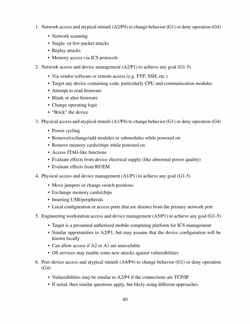
1. Network access and atypical stimuli (A2/P4) to change behavior (G1) or deny operation (G4)
• Network scanning• Single- or few-packet attacks• Replay attacks• Memory access via ICS protocols
2. Network access and device management (A2/P1) to achieve any goal (G1-5)
• Via vendor software or remote access (e.g. FTP, SSH, etc.)• Target any device containing code, particularly CPU and communication modules• Attempt to read firmware• Blank or alter firmware• Change operating logic• “Brick” the device
3. Physical access and atypical stimuli (A1/P4) to change behavior (G1) or deny operation (G4)
• Power cycling• Remove/exchange/add modules or submodules while powered on• Remove memory cards/chips while powered on• Access JTAG-like functions• Evaluate effects from device electrical supply (like abnormal power quality)• Evaluate effects from RF/EM
4. Physical access and device management (A1/P1) to achieve any goal (G1-5)
• Move jumpers or change switch positions• Exchange memory cards/chips• Inserting USB/peripherals• Local configuration or access ports that are distinct from the primary network port
5. Engineering workstation access and device management (A5/P1) to achieve any goal (G1-5)
• Target is a presumed authorized mobile computing platform for ICS management• Similar opportunities to A2/P1, but may assume that the device configuration will be
known locally• Can allow access if A2 or A1 are unavailable• OS services may enable some new attacks against vulnerabilities
6. Peer device access and atypical stimuli (A4/P4) to change behavior (G1) or deny operation(G4)
• Vulnerabilities may be similar to A2/P4 if the connections are TCP/IP• If serial, then similar questions apply, but likely using different approaches
60

7. Peer device access and device management (A4/P1) to achieve any goal (G1-5)
• Only relevant if peer or subchassis communications ports allow for P1
• Vulnerabilities may be similar to A2/P1
8. Network access and privileged operational relationship (A2/P2) to obtain data (G3)
• Given the normal lack of security services for ICS protocols, this should be achievable
• Vulnerabilities are well-known, so issues should be noted with minimal resources ex-pended
9. Network access and device impersonation (A2/P3) to misrepresent state (G2)
• Similarly to A2/P2, this should be achievable
• Vulnerabilities are well-known, so issues should be noted with minimal resources ex-pended
There are other important requirements to guide the testing, especially the development of asuitable test environment. The ICS device being tested should be set up using a configurationsuitable for the application (subject to available information). Key details include:
• A varied set of components (including power supply, CPU, binary I/O, analog I/O, net-work/communications interfaces, and cyber security modules if applicable)
• Remote I/O and/or sub-chassis as reasonable and feasible (a common feature for ICS fielddevices)
• If needed, a minimal set of analog connections such as simple signal generators and me-ters (to show proper I/O and state-of-health for onboard logic; note that testers have oftenconfigured front panel LEDs to show functioning internal logic)
• Representative network connections for supervisory control (where applicable), includingmonitoring and control traffic
• Common access methods for device configuration (physical/local and network)
• Two copies of the vendor’s management software (one with the device configuration storedto test the A3 access path, and a second to exercise other P1 vulnerabilities)
61

All testing should include responsible approaches and documentation, including:
• Hypotheses
• Test requirements
• Success/fail indicators
• Test plan and execution
These elements should support the testing, but not dominate the effort. The FDAM is exploratory,and not intended to be a checklist.
Important cyber security tools that can be used during V/C (and later) testing include:
• Vendor software
• Open-source ICS protocol implementations
• IDA Pro (disassembler/debugger)
• Wireshark (network analysis)
• NMap (network mapping)
• Nessus (vulnerability scanning)
• Metasploit, Immunity Canvas, Kali Linux (penetration testing)
• Samurai STFU (electric utility ICS based penetration testing)
• Cobalt Strike (threat emulation)
• Scapy (packet manipulation)
• tcpdump/tcpreplay (packet analyzer)
• binwalk (firmware analysis)
For each vulnerability tested, the following information should be captured when feasible (thesame information suggested in Section 5.3):
• Brief vulnerability description and unique identifier
• References – public or private/government material
• Dates of discovery and last analysis (approximate if necessary)
• Vulnerability risk score and ranking
62
• Access/procedure pair and goals supported
• Testing approaches used
• Safety/damage impact given the application (if known)
– Unexpected or unpredictable physical system behavior
– Damage to physical system components
– Potential for DOS of local automated or manual control
– Potential for DOS of supervisory control
• Additional notes and analysis, if any
• Applicable mitigations, if any, and the results of testing if available
The results of the testing will be compiled and documented according to the final test report format(detailed in the next chapter).
6.3 Exploration Testing
Exploration testing proceeds similarly to V/C testing. But because the vulnerabilities being ex-plored are a result of the V/C testing, they should all be equipment- or application-specific vulner-abilities (V3/V4). Therefore, in the exploration testing phase, the V3/V4 categories are incorpo-rated. The exploratory testing proceeds from the new vulnerability/mitigation summary tables in away identical to the down-selection for the V/C testing. The steps are listed in detail below (andalso in Appendix A):
• Identify and tabulate vulnerabilities and mitigations discovered through V/C testing
• Calculate risk scores and rank all vulnerabilities (check that all are V3 or V4)
• Tabulate vulnerabilities, their risk scores/ranks, and mitigations into APPs bands
• Down-select the vulnerabilities to be tested (same rules as V/C testing)
• Down-select mitigations associated with the vulnerabilities based on achievability and effec-tiveness
• Finalize the list of vulnerabilities (all should be V3 or V4) and mitigations to be tested
The exploratory testing phase has many of the same requirements and suggestions as the V/Ctesting process. There is a need for a properly-configured test environment, suitable test plans,and similar software/hardware testing capabilities. The results from the exploratory testing will becaptured using the same formats shown in the prior section. When exploration testing is completed,then the final step is to assemble the test report, which is detailed in the next chapter.
63

64

Chapter 7
Conclusion: Writing a Device Test Report
This final chapter of the FDAM describes the major sections of the device final report based onexecuting the FDAM approach. The FDAM accumulates a significant body of knowledge viathe literature review, physical examination, risk scoring/ranking, test scoping, and test results arecomplete (which phases are included can be modified by the analyst based on personal experienceand project resources).
The report is narrative in nature; the outline below is a suggestion as to how to present andcompile that information to convey the thoroughness of the approach and ensure that reliable con-clusions and recommendations have been reached. The narrative also captures testing details toallow for replication and reinvestigation. The report should emphasize the identification of vulner-abilities, reducing the cyber security risk, and finally managing operational test safety – by clearlydelineating significant issues that could lead to damage or safety risks during operational testing.
Key report sections include:
• Introduction
– FDAM overview
– Background for the field device being analyzed
• Literature review and device physical examination
– Literature review sources and results
– Device physical examination (key observations, etc.)
– Summary descriptions for vulnerabilities and mitigations discovered (per the suggestedformat toward the end of Section )
• Verification/characterization testing
– Scoping; the down-selection process to identify vulnerabilities and mitigations to betested (see Appendix A)
– Testing setup and background
– Testing results (also using the summary format then applicable; V/C realists may beselected for further exploratory testing)
65

• Exploration testing
– Scoping; down-select the vulnerabilities and mitigations to be tested based on V/Ctesting (see Appendix A)
– Testing setup and background (may be similar to V/C tests, e.g. the device configura-tion and lab equipment)
– Testing results, scored and summarized
• Summary
– Conclusions
* Summarize all vulnerabilities, risk scores, and if they were tested
* Summarize all mitigations, what vulnerabilities they address, if they were tested,and whether they can be added to operational systems
* Summarize the concerns for operational testing, and applicable controls to managedamage/safety risks
– Recommendations
* Vulnerabilities in most need of being addressed, and necessary follow-on analysis
* How mitigations should be implemented to reduce risk without unreasonable im-pacts to operation
* Other tests that may be needed to fully characterize operational test safety
Each of the major sections is addressed individually in the subsequent sections.
7.1 Introduction
A brief overview of the FDAM process should be included in the final report. Also, a suggestedoutline for reporting the device background information includes:
• Background - what is being tested and why
• (optional) History of the device under test
– Application space (historical and evolving)
– Production timeline
– Vendor background
• Basic overview of the device construction
– Hardware modules
– Chassis communications
– Software architecture
66

• Administration/lifecycle procedures
– Configuration/programming process
– Firmware update process
– Cyber security capabilities, including recovery/restoration
• (optional) Application focus (specifically for this report, e.g. ship systems, manufacturing,etc.)
• (optional) Known incidents (the specificity will impact the final report’s sensitivity)
7.2 Literature Review and Device Physical Examination
This section is composed as a narrative of the activities that were pursued and the vulnerabili-ties and mitigations that were discovered as part of the literature review and device examination(Chapter 5). It should include the tools, sources, and methods that were employed as part of theprocess.
7.2.1 Literature Review
The literature review (Section 5.1) is aimed at finding all the vulnerabilities and mitigations avail-able from relevant cyber security-based websites, conference proceedings, manufacturers websites,and other relevant subject matter discussion boards. This section of the report should briefly sum-marize all the vulnerabilities and mitigations found.
7.2.2 Device Physical Examination
If the device is able to be examined physically, this section will consist of a narrative detailing theapproach used, and should include a detailed description of the major components (Section 5.2).These components include the CPU, CP/network cards, debug and console ports, other connectionports such as slots for memory or storage cards,volatile and non-volatile memory, printed circuitboards, etc. Vulnerabilities based on the devices physical components should be captured.
7.2.3 Vulnerabilities and Mitigations Discovered
The literature review and device physical examination leverages any available information (pos-sibly limited by the assessment scope, e.g. classified/unclassified data, public/government infor-mation, etc.) to develop an overview of cyber vulnerabilities and possible mitigations. Once the
67

device background has been detailed, and a thorough physical examination has been performed(if possible), a table listing all vulnerabilities and mitigations discovered should be created per thesuggested format toward the end of Section .
Of particular importance are the application context (if known) and known incidents for thespecific device and application space. Vulnerabilities should include common problems (like well-known issues with ICS technology and architectures) as well as specific risks (for example, avulnerability to crashing when scanned from the network, or devices freezing if communicationis lost). Countermeasures range from general cyber fixes (e.g. external security enhancement likeVPN encapsulation) to specific cyber fixes (e.g. configuring onboard security measures).
7.3 Verification/Characterization Testing
The focus in this section should be on the approach used to decide which vulnerabilities and miti-gations should be further investigated through testing, the test approaches that were used, and howto leverage existing ICS testing capabilities whenever possible. The process used to scope the vul-nerabilities and mitigations selected to be tested, and the testing setup and testing process should bedescribed. Key to this report section is how the prioritized APPs guide the testing process. Recallfrom Chapter 3 that each APP listed a set of potential approaches to test vulnerabilities discoveredduring the literature review and device physical examination (“verification”), but also to possiblyuncover other vulnerabilities (“characterization,” which will be further investigated in explorationtesting). All approaches used should be noted, as well as any additional vulnerabilities that wereuncovered.
7.3.1 Verification/Characterization Test Scoping
The test scoping process is described in Section 6.1, and there is an example in Appendix A. Theinformation captured per the example should be reported here. The down-selected verification testscope will necessarily be augmented by characterization testing.
7.3.2 Verification/Characterization Test Setup and Background
This section describes how the testing was set up and the tools used to perform the testing (Section7.2.3). The report should cover things that were considered and ultimately incorporated during theV/C testing such how the testing components (power supply, network/communication interfaces,etc.) were set up, access methods that could be used for device configuration, vendor software usedfor device access and management, etc.
68

The test requirements, success/fail indicators, and an overview of the test plan should be de-scribed. This section should also discuss the cyber security tools used during the testing, suchas vendor software, penetration testing, firmware analysis, network analysis, packet manipulation,etc.
Recall from Section 7.2.3 and Chapter 3 that the FDAM has numerous suggestions for testingapproaches within each of the APPs that cover both verification and characterization. The finaldevice report should note which of these approaches were used.
7.3.3 Verification/Characterization Testing Results
For each vulnerability or mitigation tested, the following information should be captured (refer-encing Section 5.3):
• Vulnerability description
• References (public or private/government material)
• Dates of discovery and last analysis (approximate if necessary)
• APP association, and goals supported
• Vulnerability risk score and ranking
• Testing approaches used
• Safety/damage impact given the application (if known)
– Potential unexpected or unpredictable behavior during OT&E
– Potential damage to underlying physical system components
– Denial of service for local automated or manual control
– Denial of service to supervisory control
• Additional notes and analysis, if any
• Additional vulnerabilities discovered (to be tested later during Exploration testing)
69

7.4 Exploration Testing
The focus of exploration testing is to further develop vulnerabilities/mitigations discovered as aresult of completing V/C testing. Test procedures are similar to V/C testing. The only differenceis that fewer vulnerability category types (only V3 and V4, described in Chapter 2) are coveredbecause the goal of exploration testing is to test specific vulnerabilities. The vulnerabilities arescored and listed from lowest to highest score, along with their risk score ranking and vulnerabilitycategory.
The test scoping process is similar to the one used for V/C tests, and again the example inAppendix A is useful. Note that an exploration testing background and set up section may not berequired, as it is expected to be similar to the V/C configuration (Section 6.3). The results will alsobe tabulated in the summary format, with the only exception being that all results should coveronly vulnerabilities specific to the device or application (V3/V4).
7.5 Device Report Summary
The summary of the FDAM work for the specific device is critical to communicating the results.The first section covers the conclusions. A good approach would be to cover vulnerabilities, mit-igations, and operational test safety concerns separately. One table will summarize the vulnera-bilities, including the unique identifier (like the example ones in Section 5.3 or Appendix Aex),risk score and ranking, and whether they were tested. A second table includes mitigations, whichvulnerabilities they would improve, if they were tested, and if they can be retrofitted to existingsystems and designs (as some mitigations may need to be included at the design stage). Finally,the conclusions should include cover all of the potential OT&E test concerns, especially controlsto avoid damage/safety risks, possibly as specific ROE.
Following the conclusions are the recommendations. Very likely, there will be broad caveats fordeploying the tested field device and suggestions or requirements for further analysis. This sectionshould also note the depth of analysis achieved for the current effort, and how additional workcould logically build on the existing knowledge. If feasible, the discussion should leverage thevulnerability work to determine priority for risk mitigation. Also, the mitigations can be consideredin terms of cost/benefit, and which are most likely to avoid unreasonable impacts to operations.Finally, the recommendations should also discuss what are other tests may be needed to fullycharacterize operational test safety.
70

References
[1] Director, Operational Test and Evaluation (DOT&E), “Cybersecurity Test and EvaluationGuidebook,” Department of Defense (DOD), policy reference, July 2015.
[2] Office of the Under Secretary of Defense for Acquisition, Technology and Logistics, “DODInstruction 5000.02,” DOD, Tech. Rep., January 2015.
[3] J. Michael Gilmore, “Procedures for Operational Test and Evaluation of Cybersecurity in Ac-quisition Programs,” DOT&E, Washington, DC, memorandum, August 2014.
[4] Chief Information Officer, “DOD Cybersecurity Discipline,” DOD, implementation plan,February 2016.
[5] Chief Information Officer, “Cybersecurity Activities Support to DOD Information NetworkOperations,” DOD, policy instruction, March 2016.
[6] J. Mulder, M. Schwartz, M. Berg et al., “Understanding Programmable Logic Controllers:Joint Control System Work (JCSW) LDRD Final Report,” Sandia National Laboratories(SNL), Albuquerque, NM, Sandia Report SAND2011-7009, September 2011, document isUnclassified // Official Use Only.
[7] J. Mulder, M. Schwartz, M. Berg et al., “WeaselBoard: Zero-Day Exploit Detection for Pro-grammable Logic Controllers,” SNL, Albuquerque, NM, Sandia Report SAND2013-8274, Oc-tober 2013.
[8] L. Blinde, (2016) “PFP Cybersecurity announces DARPA award for Leveraging the AnalogDomain,” http://intelligencecommunitynews.com/pfp-cybersecurity-announces-darpa-award-for-leveraging-the-analog-domain/, online; accessed 07 SEP 2016.
71

72

Appendix A
FDAM Test Scoping Example
A.1 Verification/Characterization Testing Selection Process
The literature review and physical examination will result in a list of vulnerabilities and mitiga-tions. The following example shows how the FDAM approach can be used to narrow down whatshould be tested in both verification and exploration testing.
For this example, assume the following:
• The literature review and physical examination uncovered 13 vulnerabilities and 8 mitiga-tions
• Vulnerabilities are labeled VA through VM
• Mitigations are labeled MA through MH
All vulnerabilities need to be scored and ranked using the risk score calculations in Chapter 4.Recall that the risk scores have been prioritized as shown in Table A.1.
Rating Risk Score
None 0.0 - 0.1Low 0.1 - 3.9
Medium 4.0 - 6.9High 7.0 - 8.9
Critical 9.0 - 10.0
Table A.1: Qualitative severity rating scale
73

To date, there is no mitigation risk score calculation that would be applicable for FDAM. Con-sequently, mitigations are initially categorized by associating them with the vulnerabilities theycan address. Table A.2 shows the list of vulnerabilities to be considered (VA through VM), theirrisk score, the ranking according to Table A.1, and the associated mitigations. Note that somemitigations might be applicable to one or more vulnerabilities.
Vulner- Associatedability Risk Rank Mitigations
VA 2.2 Low MA, MBVB 3.2 Low MC, MF , MHVC 3.6 Low MGVD 3.6 Low MB, MFVE 3.9 Low MA, MBVF 5.6 Medium MB, MEVG 6.1 Medium MDVH 6.9 Medium MB, MHVI 8.1 High MDVJ 8.3 High MDVK 8.7 High MHVL 9.1 Critical ME , MHVM 9.2 Critical MA, ME
Table A.2: The vulnerabilities found in the literature review and physical examination are listedin order of their scores; associated ranks and mitigations are also listed
74

The next step in the process is to associate the vulnerabilities with the appropriate access/procedurepairs (APPs). Recall from Chapter 3 that the APPs are presented in order of priority. In Table A.3,the prioritized APP list is divided into bands. Within each band is a rule that determines the ranksof the vulnerabilities to be tested.
Ordered VulnerabilityAC-APPs Test Rule
A2-P4 (G1, G4)
Test AllA2-P1 (G1–G5)A1-P4 (G1, G5)A1-P1 (G1–G5)
A5-P1 (G1–G5) Test Critical,High,
MediumA4-P4 (G1, G4)A4-P1 (G1–G5)
A2-P2 (G3) Test Critical& HighA2-P3 (G2)
Table A.3: Listing APPs according to priority, and then dividing into sections that determine whichvulnerabilities should be tested in each band
75

Based on Table A.3, vulnerabilities are associated with the appropriate APP, resulting in a tablesimilar to Table A.4. Note that throughout this example the APPs listing order always remainsthe same – the vulnerabilities and mitigations changed positions. For illustrative purposes, theassociated mitigations column has been moved off to the right side.
Ordered Vulner- Test Vulnerability AssociatedAC-APPs ability Risk Rank Vulnerability? Test Rule Mitigations
A2-P4 (G1, G4) VE 3.9 Low Yes
Test All
MA, MBA2-P1 (G1–G5) VF 5.6 Medium Yes MB, MEA2-P1 (G1–G5) VL 9.1 Critical Yes ME , MHA1-P4 (G1, G5) VJ 8.3 High Yes MDA1-P4 (G1, G5) VM 9.2 Critical Yes MA, MEA1-P1 (G1–G5) VD 3.6 Low Yes MB, MF
A5-P1 (G1–G5) VH 6.9 Medium YesTest Critical,
High,Medium
MB, MHA4-P4 (G1, G4) VC 3.6 Low No MGA4-P4 (G1, G4) VI 8.1 High Yes MDA4-P1 (G1–G5) VK 8.7 High Yes MHA4-P1 (G1–G5) VB 3.2 Low No MC, MF , MH
A2-P2 (G3) VG 6.1 Medium No Test Critical& High
MDA2-P3 (G2) VA 2.2 Low No MA, MB
Table A.4: The vulnerabilities (Table A.2) are associated with the appropriate APPs and test cri-teria (Table A.3) to determine testing requirements; in this example, VA, VB, VC, and VG will not betested
76

Based on Table A.4, the final cut of vulnerabilities to be tested is shown in Table A.5. Notethat mitigations are not narrowed down at this point, but will be addressed in the next step.
Ordered Vulner- Test AssociatedAC-APPs ability Risk Rank Vulnerability? Mitigations
A2-P4 (G1, G4) VE 3.9 Low Yes MA, MBA2-P1 (G1–G5) VF 5.6 Medium Yes MB, MEA2-P1 (G1–G5) VL 9.1 Critical Yes ME , MHA1-P4 (G1, G5) VJ 8.3 High Yes MDA1-P4 (G1, G5) VM 9.2 Critical Yes MA, MEA1-P1 (G1–G5) VD 3.6 Low Yes MB, MF
A5-P1 (G1–G5) VH 6.9 Medium Yes MB, MHA4-P4 (G1, G4) VI 8.1 High Yes MDA4-P1 (G1–G5) VK 8.7 High Yes MH
Table A.5: The final vulnerabilities test set is determined; mitigations have not been down selectedyet
The following step is to narrow down the mitigations to be tested. Clearly, only mitigationsassociated with vulnerabilities that are to be tested are considered. Although mitigations follow thevulnerabilities throughout the scoping process, in the final analysis, each one needs to be looked atcarefully to determine if it is achievable, effective, and worthwhile.
• Achievable: Assess if the mitigation is too expensive (e.g. having guards stationed at farmore locations), or if it something that ca actually be done at this stage (i.e. conformalcoating is a design-stage issue, not suitable for retrofitting). As another example, replac-ing legacy equipment with new simply to get a security advantage might not be financiallyreasonable. However, testing a patch and then applying it is probably achievable.
• Effective: Assess if the mitigation could cause more problems than it solves. As an exam-ple, programmable logic controllers (PLCs) could all be completely isolated from other net-works, but that could affect important data or mission needs. However, it might be perfectlyacceptable to prevent web access to the PLCs and not impact their effectiveness. Considerif the mitigation would only protect against a very small or unlikely vulnerability. Shouldresources be used elsewhere to implement mitigations that can resolve several more pressingvulnerabilities?
77

In this example, assume that after careful consideration only thee mitigations have been se-lected for testing – MD, ME , and MH . Adding that information to Table A.5 gives the list of finalvulnerability/mitigation test requirements as shown in Table A.6.
Ordered Vulner- MitigationsAC-APPs ability to Test
A2-P4 (G1, G4) VE noneA2-P1 (G1–G5) VF MEA2-P1 (G1–G5) VL ME , MHA1-P4 (G1, G5) VJ MDA1-P4 (G1, G5) VM MEA1-P1 (G1–G5) VD none
A5-P1 (G1–G5) VH MHA4-P4 (G1, G4) VI MDA4-P1 (G1–G5) VK none
Table A.6: The final vulnerabilities and mitigations to be tested in the V/C phase
This information informs potential test approaches to test the requirements set shown in TableA.6 (the “Verification” part) as well as opportunities to discover new vulnerabilities (the “charac-terization” part). The latter will be down-scoped for exploration testing.
A.2 Exploration Phase Testing Selections
During V/C testing, new vulnerabilities and mitigations may be discovered that need to be tested.Recall from Chapter 2 that vulnerabilities fall into four categories:
• V1: Common problems/networking and communications
• V2: Common problems/architecture and management
• V3: Equipment-specific problems
• V4: Context- or application-specific problems
All of the vulnerabilities uncovered in the V/C testing should fall into the V3 and V4 categories.There should not be any new V1 or V2 found because these are general and should have beenuncovered during the literature review or physical examination. The goal of exploration testing isto test equipment specific vulnerabilities (V3 and V4).
78

Using the same example above, assume that eight new vulnerabilities were uncovered duringthe V/C testing. They are labeled VN through VU . Just as in the V/C testing, the risk scores foreach needs to be calculated and the vulnerabilities are listed from lowest to highest score, alongwith their risk score ranking. The only additional step is to also list each vulnerability’s category(V1-V4), as shown in Table A.7. As mentioned, they should all fall under the V3 and V4 categories– listing the category is simply a precautionary measure to ensure that this is the case.
Vulner- V3 Associatedability Risk Rank or V4 Mitigations
VN 2.3 Low V3 MB, MIVO 3.2 Low V3 MF , MJVP 3.6 Low V4 MMVQ 6.6 Medium V3 MB, MJVR 6.9 Medium V3 MA, MIVS 8.3 High V4 MB, MMVT 8.4 High V4 MEVU 9.3 Critical V3 MK, ML
Table A.7: Vulnerabilities and mitigations discovered in V/C testing are listed, along with associ-ated vulnerability categories
Subsequent steps proceed similar to prior down-selections. Mixing the vulnerabilities andassociated mitigations in Table A.7 into the APPs (Table A.3) results in Table A.8.
Ordered Vulner- V3 Test Vulnerability AssociatedAC-APPs ability Risk Rank or V4 Vulnerability? Test Rule Mitigations
A2-P4 (G1, G4) VT 8.4 High V4 Yes
Test All
MEA2-P1 (G1–G5) VU 9.3 Critical V3 Yes MK, MLA1-P4 (G1, G5) VN 2.3 Low V3 Yes MB, MIA1-P1 (G1–G5) VQ 6.6 Medium V3 Yes MB, MJ
A5-P1 (G1–G5) none N/A N/A N/A N/A Test Critical,High,
Medium
noneA4-P4 (G1, G4) VP 3.6 Low V4 No MMA4-P1 (G1–G5) VO 3.2 Low V3 No MF , MJ
A2-P2 (G3) VS 8.3 High V4 No Test Critical& High
MB, MMA2-P3 (G2) VR 6.9 Medium V3 No MA, MI
Table A.8: Vulnerabilities and mitigations found during V/C testing will be scoped down andtested in exploration testing
79

According to the prior table, it is clear to see that the first four vulnerabilities will be tested,along with the second-to-last entry. In this example, assume also that all the associated mitigationsare achievable and effective, and will also be tested. Thus, the final set of vulnerabilities andmitigations to be tested are listed in Table A.9.
Ordered Vulner- MitigationsAC-APPs ability to Test
A2-P4 (G1, G4) VT MEA2-P1 (G1–G5) VU MK, MLA1-P4 (G1, G5) VN MB, MIA1-P1 (G1–G5) VQ MB, MJ
A2-P2 (G3) VS MB, MM
Table A.9: The final vulnerabilities and mitigations to be tested in the exploratory phase
80

Appendix B
Revision History
Version Date Time Name Notes
0.1 20150810 1529 JES Initial version0.2 20150821 1428 JES Improved tools and data sources0.3 20150825 1327 JES Modified framework analysis0.4 20150924 1327 JES Added sections on prioritization0.5 20151019 1529 JES Split into two volumes and reorganized0.6 20151119 1004 JES Integrated Q1 comments0.7 20160111 0814 JES Reorganized material in Volume I0.8 20160126 1527 JES Joined volumes (Vol. II is a “cheat sheet” appendix)0.9 20160217 1655 JES Completed “first feedback” circulation draft
0.9.1 20160322 1338 JES Completed “team review” circulation draft0.9.2 20160602 1612 JES Integrated “team review” comments0.9.3 20160627 1603 JES Completed assessment process section0.9.8 20160921 1409 JAS Completed major revision0.9.9 20160929 1200 JES Finalized 2nd draft1.0 20170309 1602 JES Finalized first version
81

82

Appendix C
Contact Information
Name Organization
Sandia National LaboratoriesJason Stamp P.O. Box 5800SNL Technical Lead Albuquerque, NM 87185-0671
Sandia National LaboratoriesNick Pattengale P.O. Box 5800SNL Project Manager Albuquerque, NM 87185-0671
Sandia National LaboratoriesZach Benz P.O. Box 5800SNL Program Manager Albuquerque, NM 87185-0671
Office of the Director, Operational Test and EvaluationSteve Gates 4800 Mark Center Drive Suite 10E12DOT&E Program Manager Alexandria, VA 22311
83

84

Report Distribution
1 Steve GatesOffice of the Director, Operational Test and Evaluation4800 Mark Center Drive Suite 10E12Alexandria, Virginia 22311
1 John BurnsOffice of the Director, Operational Test and Evaluation4800 Mark Center Drive Suite 10E12Alexandria, Virginia 22311
1 MS0671 Zach Benz, 56241 MS0671 Chris Davis, 56241 MS0671 Jennifer Depoy, 56281 MS0671 Dan Fay, 56271 MS0671 Mitch Martin, 56271 MS0671 Nick Pattengale, 56241 MS0671 Neeta Rattan, 56231 MS0671 Jason Stamp, 56231 MS0757 Tricia Schulz, 66131 MS0899 RIM-Reports Management, 9532 (electronic copy)
85

86

v1.32JES
87